husky 205 air–operated diaphragm...
TRANSCRIPT
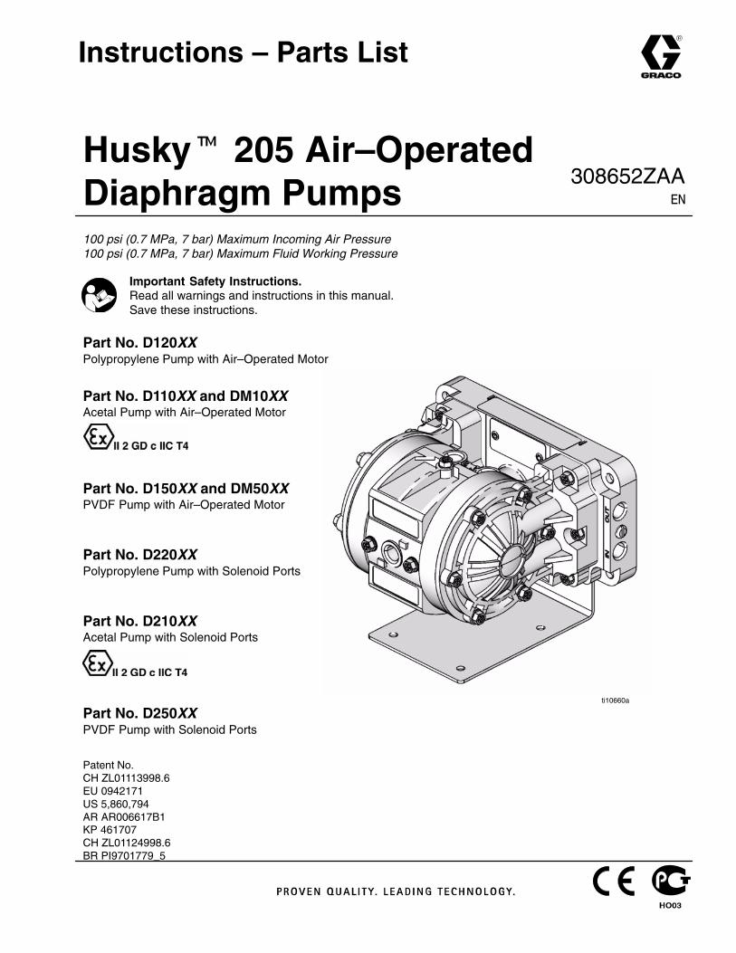
Husky� 205 Air–OperatedDiaphragm Pumps100 psi (0.7 MPa, 7 bar) Maximum Incoming Air Pressure100 psi (0.7 MPa, 7 bar) Maximum Fluid Working Pressure
Part No. D120XXPolypropylene Pump with Air–Operated Motor
Part No. D110XX and DM10XXAcetal Pump with Air–Operated Motor
Part No. D150XX and DM50XXPVDF Pump with Air–Operated Motor
Part No. D220XXPolypropylene Pump with Solenoid Ports
Part No. D210XXAcetal Pump with Solenoid Ports
Part No. D250XXPVDF Pump with Solenoid Ports
Patent No.CH ZL01113998.6EU 0942171US 5,860,794AR AR006617B1KP 461707CH ZL01124998.6BR PI9701779_5
Instructions – Parts List
Important Safety Instructions.Read all warnings and instructions in this manual.Save these instructions.
ti10660a
308652ZAA��
2 308652
ContentsWarnings 2. . . . . . . . . . . . . . . . . . . . . . . . . . . . . . . . . . . . . Installation 4. . . . . . . . . . . . . . . . . . . . . . . . . . . . . . . . . . . . Operation 8. . . . . . . . . . . . . . . . . . . . . . . . . . . . . . . . . . . . . Maintenance 9. . . . . . . . . . . . . . . . . . . . . . . . . . . . . . . . . . . Troubleshooting 10. . . . . . . . . . . . . . . . . . . . . . . . . . . . . . . Service 12. . . . . . . . . . . . . . . . . . . . . . . . . . . . . . . . . . . . . . Parts Matrix 15. . . . . . . . . . . . . . . . . . . . . . . . . . . . . . . . . . Service Kit Matrix 15. . . . . . . . . . . . . . . . . . . . . . . . . . . . . Parts Lists 16. . . . . . . . . . . . . . . . . . . . . . . . . . . . . . . . . . . . Parts Drawing 17. . . . . . . . . . . . . . . . . . . . . . . . . . . . . . . . . Torque Sequence 18. . . . . . . . . . . . . . . . . . . . . . . . . . . . . Technical Data 19. . . . . . . . . . . . . . . . . . . . . . . . . . . . . . . . Dimensions and Mounting Hole Layout 20. . . . . . . . . . . Performance Charts 21. . . . . . . . . . . . . . . . . . . . . . . . . . . Graco Standard Warranty 24. . . . . . . . . . . . . . . . . . . . . . Graco Information 24. . . . . . . . . . . . . . . . . . . . . . . . . . . . .
Warning Symbol
WARNINGThis symbol alerts you to the possibility of seriousinjury or death if you do not follow the instructions.
Caution Symbol
CAUTIONThis symbol alerts you to the possibility of damage toor destruction of equipment if you do not follow theinstructions.
EQUIPMENT MISUSE HAZARD
Any misuse of the equipment or accessories, such as overpressurizing, modifying parts, usingincompatible chemicals and fluids, or using worn or damaged parts, can cause them to rupture andresult in splashing in the eyes or on the skin, other serious injury, or fire, explosion or property dam-age.
� This equipment is for professional use only. Observe all warnings. Read and understand allinstruction manuals, warning labels, and tags before you operate this equipment. If you are notsure, or if you have questions about installation or operation, call your Graco distributor.
� Never alter or modify any part of this equipment; doing so could cause it to malfunction. Use onlygenuine Graco part numbers and accessories.
� Check all equipment regularly and repair or replace worn or damaged parts immediately.
� Never exceed the recommended working pressure or the maximum air inlet pressure stated onyour pump or in the Technical Data on page 19.
� Do not exceed the maximum working pressure of the lowest rated component in your system.This equipment has a 100 psi (0.7 MPa, 7 bar) maximum working pressure at 100 psi(0.7 MPa, 7 bar, ) maximum incoming air pressure.
� Be sure that all fluids and solvents used are chemically compatible with the wetted parts shown inthe Technical Data on page 19. Always read the manufacturer’s literature before you use fluidor solvent in the pump.
� Never move or lift a pump under pressure. If dropped, the fluid section may rupture. Alwaysfollow the Pressure Relief Procedure on page 8 before you move or lift the pump.
� Never use a polypropylene or PVDF pump with non-conductive flammable fluids as specified byyour local fire protection code. Refer to Grounding on page 4 for additional information. Consultyour fluid supplier to determine the conductivity or resistivity of your fluid.
� Provide fresh air ventilation to avoid the buildup of flammable fumes from solvents or the fluidbeing pumped.
WARNING
3308652
HAZARDOUS FLUIDS
Improper handling of hazardous fluids or inhaling toxic vapors can cause extremely serious injury ordeath from splashing in the eyes, ingestion, or bodily contamination. Observe all the followingprecautions when you handle hazardous or potentially hazardous fluids.
� Know what fluid you are pumping and its specific hazards. Take precautions to avoid a toxic fluidspill.
� Always wear appropriate clothing and equipment, such as eye protection and breathing appara-tus, to protect yourself.
� Store hazardous fluid in an appropriate, approved container. Dispose of it according to all Local,State, and Federal guidelines for hazardous fluids.
� Secure the fluid outlet hose tightly into the receiving container to prevent it from coming looseand improperly draining the fluid.
� Pipe and dispose of the exhaust air safely, away from people, animals, and food handling areas.If the diaphragm fails, the fluid is exhausted along with the air. See Air Exhaust Ventilation onpage 5.
FIRE AND EXPLOSION HAZARD
Static electricity is created by the flow of fluid through the pump and hose. If the equipment is notproperly grounded, sparking may occur. Sparks can ignite fumes from solvents and the fluid beingpumped, dust particles, and other flammable substances, whether you are pumping indoors oroutdoors, and can cause a fire or explosion and serious injury and property damage.
� To reduce the risk of static sparking, ground the pump and all other equipment used or located inthe work area. Check your local electrical code for detailed grounding instructions for your areaand type of equipment. See Grounding on page 4.
� If you experience any static sparking or even a slight shock while using this equipment, stoppumping immediately. Check the entire system for proper grounding. Do not use the systemagain until you have identified and corrected the problem.
� Pipe and dispose of the exhaust air safely, away from all sources of ignition. If the diaphragmfails, the fluid is exhausted along with the air. See Air Exhaust Ventilation on page 5.
� Do not smoke in the work area. Do not operate the equipment near a source of ignition or anopen flame, such as a pilot light.
WARNING
United States Government safety standards have been adopted under the Occupational Safety and Health Act.You should consult these standards—particularly the General Standards, Part 1910, and the Construction Stan-dards, Part 1926.
4 308652
InstallationTightening Threaded Fasteners BeforeFirst Use
Before using the pump for the first time, check andretorque all external fasteners. See Torque Se-quence, page 18. After the first day of operation,retorque the fasteners. Although pump use varies, ageneral guideline is to retorque fasteners every twomonths.
Use a compatible thread sealant on all male threads.Tighten all connections firmly to avoid air or fluid leaks.
CAUTIONTo avoid pump damage, do not overtighten thefittings to the pump.
Grounding
WARNINGFIRE AND EXPLOSION HAZARDThis pump must be grounded. Beforeyou operate the pump, ground thesystem as explained below. Also readthe section FIRE AND EXPLOSIONHAZARD on page 3.
The acetal pump contains stainless steel fiberswhich make the wetted parts conductive. Attachingthe ground wire to one of the grounding locationsgrounds the wetted parts.
The polypropylene and PVDF pumps are notconductive. When you pump conductive flam-mable fluids, always ground the entire fluid systemby making sure the fluid has an electrical path to atrue earth ground. See Fig. 1. Never use a poly-propylene or PVDF pump with non-conductiveflammable fluids as specified by your local fireprotection code. Consult your fluid supplier todetermine the conductivity or resistivity of yourfluid.
US Code (NFPA 77 Static Electricity) recommendsa conductivity greater than 50 x 10–12 Siemans/me-ter (mhos/meter) over your operating temperaturerange to reduce the hazard of fire. Consult yourfluid supplier to determine the conductivity orresistivity of your fluid. The resistivity must be lessthan 2 x 10¹² ohm-centimeters.
To reduce the risk of static sparking, ground the pumpand all other equipment used or located in the pumpingarea. Check your local electrical code for detailedgrounding instructions for your area and type of equip-ment.
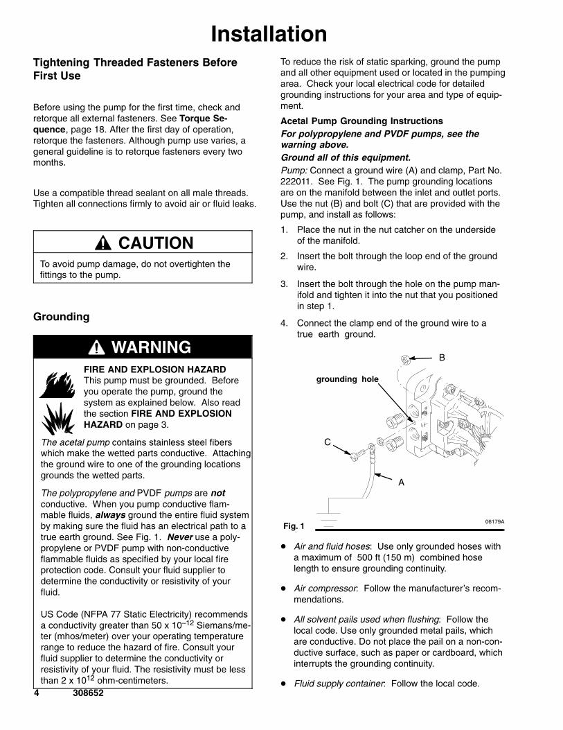
Acetal Pump Grounding InstructionsFor polypropylene and PVDF pumps, see thewarning above.Ground all of this equipment.Pump: Connect a ground wire (A) and clamp, Part No.222011. See Fig. 1. The pump grounding locationsare on the manifold between the inlet and outlet ports.Use the nut (B) and bolt (C) that are provided with thepump, and install as follows:
1. Place the nut in the nut catcher on the undersideof the manifold.
2. Insert the bolt through the loop end of the groundwire.
3. Insert the bolt through the hole on the pump man-ifold and tighten it into the nut that you positionedin step 1.
4. Connect the clamp end of the ground wire to atrue earth ground.
Fig. 106179A
Fig. 1
A
C
grounding hole
B
� Air and fluid hoses: Use only grounded hoses witha maximum of 500 ft (150 m) combined hoselength to ensure grounding continuity.
� Air compressor: Follow the manufacturer’s recom-mendations.
� All solvent pails used when flushing: Follow thelocal code. Use only grounded metal pails, whichare conductive. Do not place the pail on a non-con-ductive surface, such as paper or cardboard, whichinterrupts the grounding continuity.
� Fluid supply container: Follow the local code.
5308652
InstallationAir Exhaust Ventilation
WARNINGTOXIC FLUID HAZARD
Read the USING HAZARDOUS FLUIDSand FIRE AND EXPLOSION HAZARDsections on page 3 before you operatethis pump.
Be sure the system is properly ventilatedfor your type of installation. You mustvent the exhaust to a safe place, awayfrom people, animals or food handlingareas when pumping flammable orhazardous fluids.
If the diaphragm ruptures, the fluid being pumpedis exhausted with the air. Place a container at theend of the air exhaust line to catch fluid in case thediaphragm ruptures, and disconnect the pump.
Mountings
CAUTIONThe pump exhaust air may contain contaminants.If needed, ventilate to a remote area to reducepossible fluid contamination. See Air ExhaustVentilation on page 5.
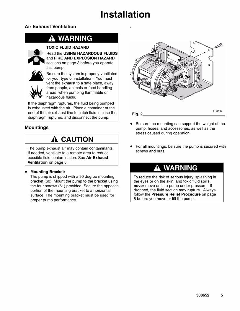
� Mounting Bracket: The pump is shipped with a 90 degree mountingbracket (60). Mount the pump to the bracket usingthe four screws (61) provided. Secure the oppositeportion of the mounting bracket to a horizontalsurface. The mounting bracket must be used forproper pump performance.
.
Fig. 2ti10662a
� Be sure the mounting can support the weight of thepump, hoses, and accessories, as well as thestress caused during operation.
� For all mountings, be sure the pump is secured withscrews and nuts.
WARNINGTo reduce the risk of serious injury, splashing inthe eyes or on the skin, and toxic fluid spills,never move or lift a pump under pressure. Ifdropped, the fluid section may rupture. Alwaysfollow the Pressure Relief Procedure on page8 before you move or lift the pump.
6 308652
InstallationAir Lines
WARNINGBleed-Type Master Air Valve and Fluid DrainValve
A bleed-type master air valve and a fluid drainvalve are required on your system.
The bleed-type master air valve relieves airtrapped between itself and the pump. Trapped aircan cause the pump to cycle unexpectedly, whichcould result in serious bodily injury, includingsplashing in the eyes, injury from moving parts, orcontamination from hazardous fluids.
The fluid drain valve reduces the risk of seriousbodily injury, including splashing in the eyes or onthe skin, or contamination from hazardous fluids.Install the fluid drain valve close to the pump’sfluid outlet to relieve pressure in the hose if thehose becomes plugged.
1. Mount the air line accessories on the wall or on abracket. Be sure the air line supplying the acces-sories is grounded.
a. The pump speed can be controlled in one oftwo ways: To control it on the air side, installan air regulator. To control it on the fluid side,install a fluid valve near the outlet.
b. Install a bleed-type master air valve down-stream from the air regulator, and use it to re-lieve trapped air. See the Bleed-Type MasterAir Valve and Fluid Drain Valve warningabove. Locate another bleed-type master airvalve upstream from all air line accessories,and use it to isolate the accessories duringcleaning and repair.
c. The air line filter removes harmful dirt andmoisture from the compressed air supply.
2. Install a flexible air hose between the accessoriesand the pump air inlet. Screw the air line fittinginto the air inlet.
3. Do not restrict the exhaust port. Excessive ex-haust restriction can cause erratic pump operation.
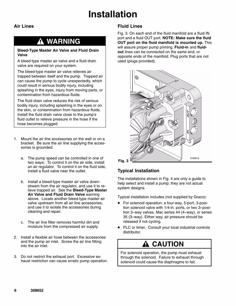
Fluid LinesFig. 3. On each end of the fluid manifold are a fluid INport and a fluid OUT port. NOTE: Make sure the fluidOUT port on the fluid manifold is mounted up. Thiswill assure proper pump priming. Fluid-in and fluid-out lines can be connected on the same end, oropposite ends of the manifold. Plug ports that are notused (plugs provided).
Fig. 3 06179Ati10661a
Typical Installation
The installations shown in Fig. 4 are only a guide tohelp select and install a pump; they are not actualsystem designs.
Typical installation includes (not supplied by Graco):
� For solenoid operation: a four-way, 5-port, 3-posi-tion solenoid valve with 1/4-in. ports, or two 3–posi-tion 3–way valves. Mac series 44 (4–way), or series35 (3–way). Either way, air pressure should bereleased if not cycling.
� PLC or timer. Consult your local industrial controlsdistributor.
For solenoid operation, the pump must exhaustthrough the solenoid. Failure to exhaust throughsolenoid could cause the diaphragms to fail.
CAUTION
7308652
Installation
Fig. 4
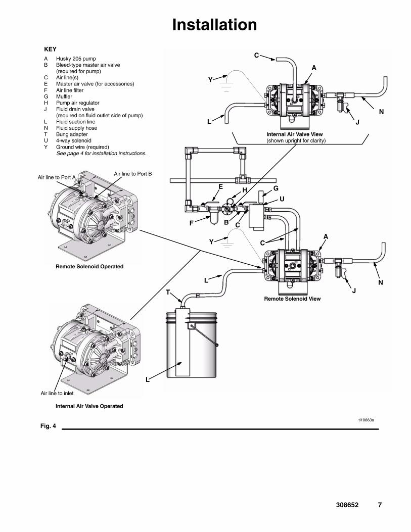
KEY
A Husky 205 pumpB Bleed-type master air valve
(required for pump)C Air line(s)E Master air valve (for accessories)F Air line filterG MufflerH Pump air regulatorJ Fluid drain valve
(required on fluid outlet side of pump)L Fluid suction lineN Fluid supply hoseT Bung adapterU 4-way solenoidY Ground wire (required)
See page 4 for installation instructions.
C
J
L
NT
YA
U
Air line to inlet
Internal Air Valve Operated
Remote Solenoid Operated
E H
B
G
F
Remote Solenoid View
Internal Air Valve View(shown upright for clarity)
C
J
N
A
L
L
C
Air line to Port AAir line to Port B
Y
ti10663a
8 308652
OperationPressure Relief Procedure
WARNINGTo reduce the risk of serious injury, includingsplashing fluid in the eyes or on the skin, follow thisprocedure whenever you are instructed to relievepressure, when you shut off the pump, and beforeyou check, adjust, clean, move, or repair anysystem equipment.
1. Shut off air and reserve air to the pump.
2. Open the dispensing valve if the system has one.
3. Open the fluid drain valve to relieve all systempressure, and have a container ready to catch thedrainage.
Flushing the Pump Before First UseThe pump was tested in water. If water could contami-nate the fluid you are pumping, flush it thoroughly witha compatible solvent. Follow the procedure in Start-ing and Adjusting the Pump.
Starting and Adjusting the Pump
WARNINGTo reduce the risk of serious injury, splashing inthe eyes or on the skin, and toxic fluid spills,never move or lift a pump under pressure. If thepump is dropped, the fluid section could rupture.Always follow the Pressure Relief Procedureabove before you move or lift the pump.
1. Be sure the pump is properly grounded. Read andfollow the instructions in Grounding on page 4.
2. Check all fittings to be sure they are tight. Be sureto use a compatible liquid thread sealant on allmale threads. Tighten the fluid inlet and outlet fit-tings and plugs securely. Retorque all fastenersbefore start-up. See Torque Sequence, page 18.
3. Place the suction tube (if used) in the fluid to bepumped.
4. Place the end of the outlet hose into an appropri-ate container.
5. Close the fluid drain valve.
6. With the air regulator closed, open all bleed-typemaster air valves.
7. If the outlet hose has a dispensing device, hold itopen while continuing with step 8.
8. Slowly open the air regulator until the pump startsto cycle. Allow the pump to cycle until all air ispushed out of the lines and the pump is primed.
NOTE: To prime a remote solenoid-operatedair valve, operate the pump at a minimum 60 cpmrate until the pump is fully primed.
Pump Shutdown
At the end of the work shift, and before you check,adjust, clean, or repair the system, relieve air andfluid pressure.
WARNINGTo reduce the risk of serious injury whenever youare instructed to relieve pressure, always follow thePressure Relief Procedure at left.
9308652
MaintenanceLubricationThe air valve is lubricated at the factory and designedto operate without additional lubrication.
If added lubrication is desired, every 500 hours ofoperation (or monthly), remove the hose from thepump air inlet and add two drops of machine oil to theair inlet.
CAUTIONDo not over-lubricate the pump. Excess oil isexhausted through the muffler, which could con-taminate your fluid supply or other equipment.
Tightening Threaded Connections
Before each use, check all hoses for wear or damage,and replace as necessary. Be sure all threaded con-nections are tight and free of leaks.
Check fasteners. Tighten or retorque as necessary.Although pump use varies, a general guideline is toretorque fasteners every two months. See TorqueSequence, page 18.
Flushing and Storage
Flush the pump to prevent the fluid from drying orfreezing in the pump and damaging it. Always flushthe pump and relieve the pressure before storing forany length of time. Use a compatible solvent.
WARNINGTo reduce the risk of serious injury whenever youare instructed to relieve pressure, always follow thePressure Relief Procedure on page 8.
If you are flushing, run the pump long enough tothoroughly clean the pump and hoses, close the airregulator, and remove the suction hose from thesolvent and place it in the fluid to be pumped.
If you are shutting down the pump, remove the suctionhose from the fluid container, run the pump until thefluid is forced out of the system, and shut off the airsupply immediately.
10 308652
TroubleshootingRelieve the pressure before you check or service theequipment.
Check all possible problems and causes before youdisassemble the pump.
WARNINGTo reduce the risk of serious injury whenever youare instructed to relieve pressure, always follow thePressure Relief Procedure on page 8.
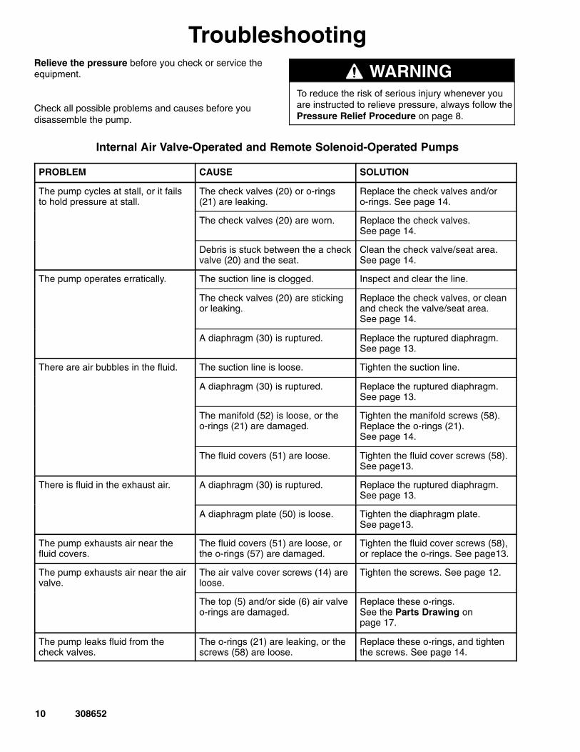
Internal Air Valve-Operated and Remote Solenoid-Operated Pumps
PROBLEM CAUSE SOLUTION
The pump cycles at stall, or it failsto hold pressure at stall.
The check valves (20) or o-rings(21) are leaking.
Replace the check valves and/oro-rings. See page 14.
The check valves (20) are worn. Replace the check valves. See page 14.
Debris is stuck between the a checkvalve (20) and the seat.
Clean the check valve/seat area.See page 14.
The pump operates erratically. The suction line is clogged. Inspect and clear the line.
The check valves (20) are stickingor leaking.
Replace the check valves, or cleanand check the valve/seat area.See page 14.
A diaphragm (30) is ruptured. Replace the ruptured diaphragm.See page 13.
There are air bubbles in the fluid. The suction line is loose. Tighten the suction line.
A diaphragm (30) is ruptured. Replace the ruptured diaphragm.See page 13.
The manifold (52) is loose, or theo-rings (21) are damaged.
Tighten the manifold screws (58).Replace the o-rings (21).See page 14.
The fluid covers (51) are loose. Tighten the fluid cover screws (58).See page13.
There is fluid in the exhaust air. A diaphragm (30) is ruptured. Replace the ruptured diaphragm.See page 13.
A diaphragm plate (50) is loose. Tighten the diaphragm plate. See page13.
The pump exhausts air near thefluid covers.
The fluid covers (51) are loose, orthe o-rings (57) are damaged.
Tighten the fluid cover screws (58),or replace the o-rings. See page13.
The pump exhausts air near the airvalve.
The air valve cover screws (14) areloose.
Tighten the screws. See page 12.
The top (5) and/or side (6) air valveo-rings are damaged.
Replace these o-rings.See the Parts Drawing onpage 17.
The pump leaks fluid from thecheck valves.
The o-rings (21) are leaking, or thescrews (58) are loose.
Replace these o-rings, and tightenthe screws. See page 14.
11308652
Troubleshooting
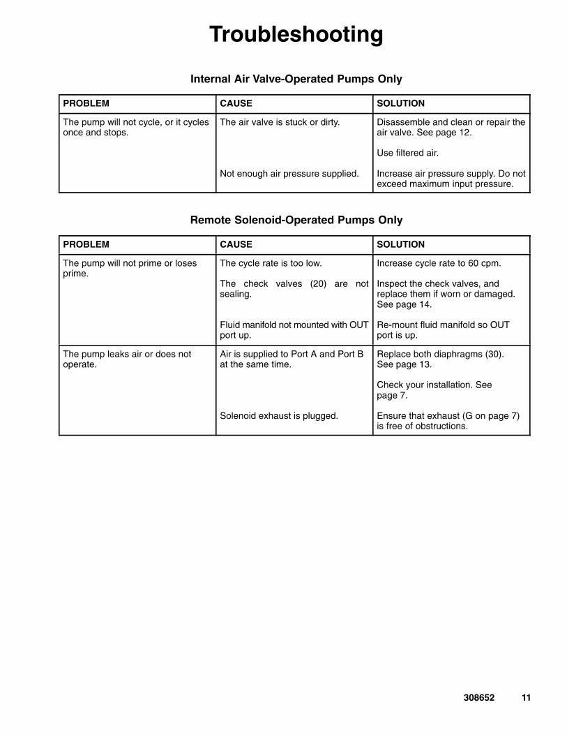
Internal Air Valve-Operated Pumps Only
PROBLEM CAUSE SOLUTION
The pump will not cycle, or it cyclesonce and stops.
The air valve is stuck or dirty.
Not enough air pressure supplied.
Disassemble and clean or repair theair valve. See page 12.
Use filtered air.
Increase air pressure supply. Do notexceed maximum input pressure.
Remote Solenoid-Operated Pumps Only
PROBLEM CAUSE SOLUTION
The pump will not prime or losesprime.
The cycle rate is too low.
The check valves (20) are notsealing.
Fluid manifold not mounted with OUTport up.
Increase cycle rate to 60 cpm.
Inspect the check valves, andreplace them if worn or damaged.See page 14.
Re-mount fluid manifold so OUTport is up.
The pump leaks air or does notoperate.
Air is supplied to Port A and Port Bat the same time.
Solenoid exhaust is plugged.
Replace both diaphragms (30).See page 13.
Check your installation. Seepage 7.
Ensure that exhaust (G on page 7)is free of obstructions.
12 308652
ServiceService KitsService Kits may be ordered separately.
To repair the air valve, order Part No. 238853. Partsincluded in the Air Valve Service Kit are marked withan asterisk in the Parts Drawing on page 17, forexample (3*).
For fluid section repair section parts, see the ServiceKit Matrix on page 15. Parts included in the FluidSection Service Kit are marked with a dagger in theParts Drawing on page 17, for example (4�).
Servicing the Air Valve
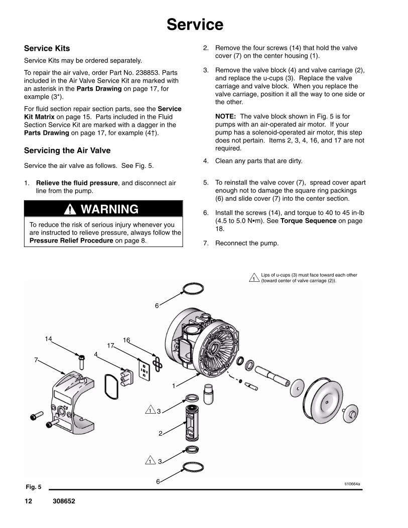
Service the air valve as follows. See Fig. 5.
1. Relieve the fluid pressure, and disconnect airline from the pump.
WARNINGTo reduce the risk of serious injury whenever youare instructed to relieve pressure, always follow thePressure Relief Procedure on page 8.
2. Remove the four screws (14) that hold the valvecover (7) on the center housing (1).
3. Remove the valve block (4) and valve carriage (2),and replace the u-cups (3). Replace the valvecarriage and valve block. When you replace thevalve carriage, position it all the way to one side orthe other.
NOTE: The valve block shown in Fig. 5 is forpumps with an air-operated air motor. If yourpump has a solenoid-operated air motor, this stepdoes not pertain. Items 2, 3, 4, 16, and 17 are notrequired.
4. Clean any parts that are dirty.
5. To reinstall the valve cover (7), spread cover apartenough not to damage the square ring packings(6) and slide cover (7) into the center section.
6. Install the screws (14), and torque to 40 to 45 in-lb(4.5 to 5.0 N�m). See Torque Sequence on page18.
7. Reconnect the pump.
Fig. 5
7
ti10664a
14
2
4
Lips of u-cups (3) must face toward each other(toward center of valve carriage (2)).1
1 3
31
1
1716
6
6
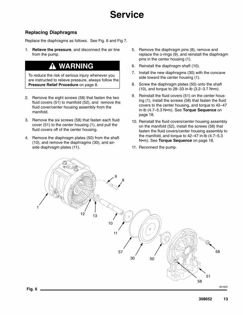
Fig. 6
5030
57
8
06180D
58
58
51
1
10
11
9
12 13
13308652
Service
Replacing Diaphragms
Replace the diaphragms as follows. See Fig. 6 and Fig 7.
1. Relieve the pressure, and disconnect the air linefrom the pump.
WARNINGTo reduce the risk of serious injury whenever youare instructed to relieve pressure, always follow thePressure Relief Procedure on page 8.
2. Remove the eight screws (58) that fasten the twofluid covers (51) to manifold (52), and remove thefluid cover/center housing assembly from themanifold.
3. Remove the six screws (58) that fasten each fluidcover (51) to the center housing (1), and pull thefluid covers off of the center housing.
4. Remove the diaphragm plates (50) from the shaft(10), and remove the diaphragms (30), and air-side diaphragm plates (11).
5. Remove the diaphragm pins (8), remove andreplace the o-rings (9), and reinstall the diaphragmpins in the center housing (1).
6. Reinstall the diaphragm shaft (10).
7. Install the new diaphragms (30) with the concaveside toward the center housing (1).
8. Screw the diaphragm plates (50) onto the shaft (10), and torque to 28–33 in-lb (3.2–3.7 N�m).
9. Reinstall the fluid covers (51) on the center hous-ing (1), install the screws (58) that fasten the fluidcovers to the center housing, and torque to 42–47in-lb (4.7–5.3 N�m). See Torque Sequence onpage 18.
10. Reinstall the fluid covers/center housing assemblyon the manifold (52), install the screws (58) thatfasten the fluid covers/center housing assembly tothe manifold, and torque to 42–47 in-lb (4.7–5.3N�m). See Torque Sequence on page 18.
11. Reconnect the pump.
14 308652
Service
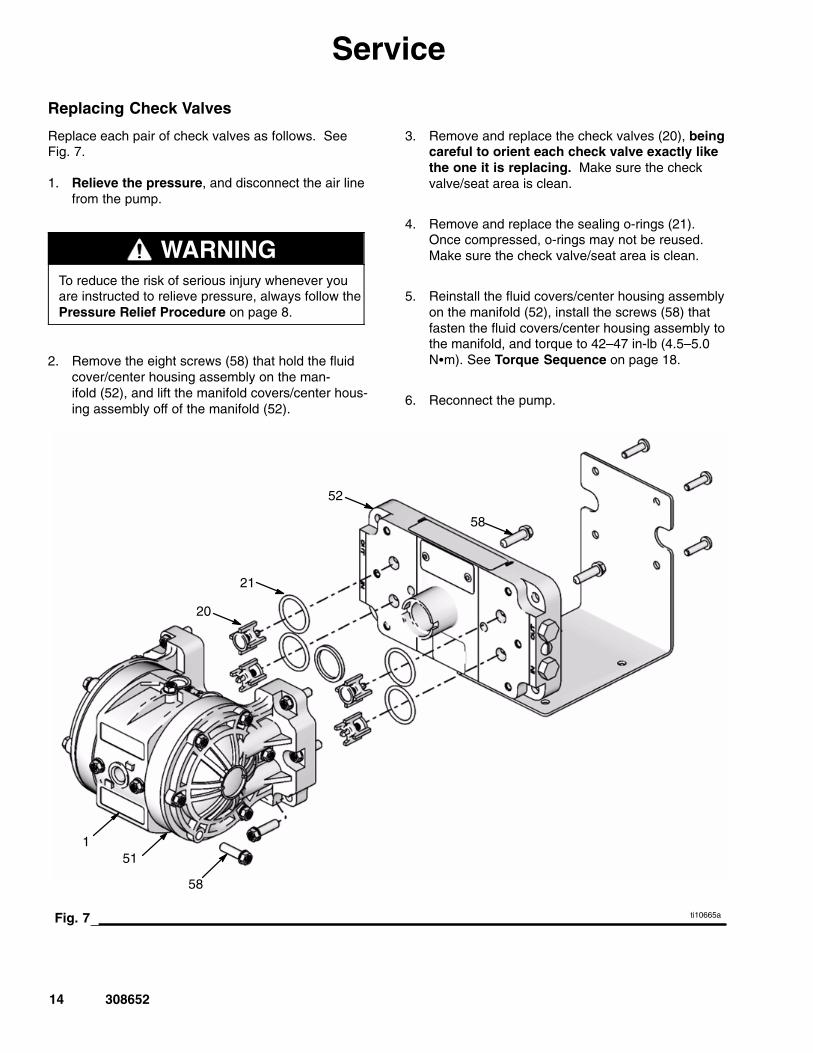
Replacing Check Valves
Replace each pair of check valves as follows. SeeFig. 7.
1. Relieve the pressure, and disconnect the air linefrom the pump.
WARNINGTo reduce the risk of serious injury whenever youare instructed to relieve pressure, always follow thePressure Relief Procedure on page 8.
2. Remove the eight screws (58) that hold the fluidcover/center housing assembly on the man-ifold (52), and lift the manifold covers/center hous-ing assembly off of the manifold (52).
3. Remove and replace the check valves (20), beingcareful to orient each check valve exactly likethe one it is replacing. Make sure the checkvalve/seat area is clean.
4. Remove and replace the sealing o-rings (21).Once compressed, o-rings may not be reused.Make sure the check valve/seat area is clean.
5. Reinstall the fluid covers/center housing assemblyon the manifold (52), install the screws (58) thatfasten the fluid covers/center housing assembly tothe manifold, and torque to 42–47 in-lb (4.5–5.0N�m). See Torque Sequence on page 18.
6. Reconnect the pump.
Fig. 7 ti10665a
1
52
21
20
51
58
58
15308652
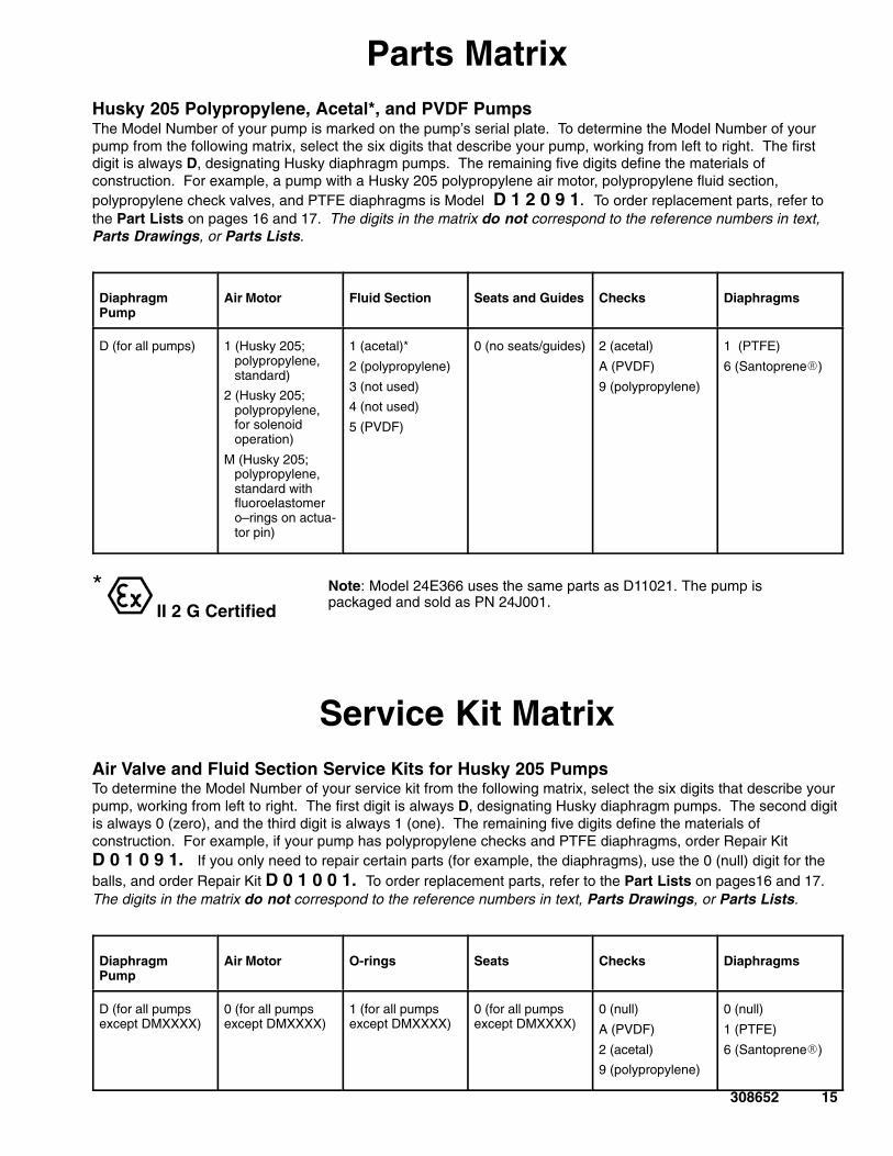
Parts MatrixHusky 205 Polypropylene, Acetal*, and PVDF PumpsThe Model Number of your pump is marked on the pump’s serial plate. To determine the Model Number of yourpump from the following matrix, select the six digits that describe your pump, working from left to right. The firstdigit is always D, designating Husky diaphragm pumps. The remaining five digits define the materials ofconstruction. For example, a pump with a Husky 205 polypropylene air motor, polypropylene fluid section,polypropylene check valves, and PTFE diaphragms is Model D 1 2 0 9 1. To order replacement parts, refer tothe Part Lists on pages 16 and 17. The digits in the matrix do not correspond to the reference numbers in text,Parts Drawings, or Parts Lists.
DiaphragmPump
Air Motor Fluid Section Seats and Guides Checks Diaphragms
D (for all pumps) 1 (Husky 205;polypropylene,standard)
2 (Husky 205;polypropylene,for solenoidoperation)
M (Husky 205;polypropylene,standard withfluoroelastomero–rings on actua-tor pin)
1 (acetal)*
2 (polypropylene)
3 (not used)
4 (not used)
5 (PVDF)
0 (no seats/guides)
2 (acetal)
A (PVDF)
9 (polypropylene)
1 (PTFE)
6 (Santoprene�)
*
II 2 G Certified
Note: Model 24E366 uses the same parts as D11021. The pump ispackaged and sold as PN 24J001.
Service Kit MatrixAir Valve and Fluid Section Service Kits for Husky 205 PumpsTo determine the Model Number of your service kit from the following matrix, select the six digits that describe yourpump, working from left to right. The first digit is always D, designating Husky diaphragm pumps. The second digitis always 0 (zero), and the third digit is always 1 (one). The remaining five digits define the materials ofconstruction. For example, if your pump has polypropylene checks and PTFE diaphragms, order Repair KitD 0 1 0 9 1. If you only need to repair certain parts (for example, the diaphragms), use the 0 (null) digit for theballs, and order Repair Kit D 0 1 0 0 1. To order replacement parts, refer to the Part Lists on pages16 and 17.The digits in the matrix do not correspond to the reference numbers in text, Parts Drawings, or Parts Lists.
DiaphragmPump
Air Motor O-rings Seats Checks Diaphragms
D (for all pumpsexcept DMXXXX)
0 (for all pumps except DMXXXX)
1 (for all pumps except DMXXXX)
0 (for all pumps except DMXXXX)
0 (null)
A (PVDF)
2 (acetal)
9 (polypropylene)
0 (null)
1 (PTFE)
6 (Santoprene�)
16 308652
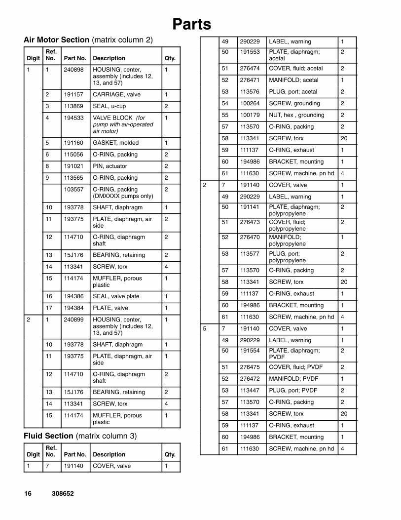
PartsAir Motor Section (matrix column 2)
DigitRef.No. Part No. Description Qty.
1 1 240898 HOUSING, center,assembly (includes 12,13, and 57)
1
2 191157 CARRIAGE, valve 1
3 113869 SEAL, u-cup 2
4 194533 VALVE BLOCK (forpump with air-operatedair motor)
1
5 191160 GASKET, molded 1
6 115056 O-RING, packing 2
8 191021 PIN, actuator 2
9 113565 O-RING, packing 2
103557 O-RING, packing(DMXXXX pumps only)
2
10 193778 SHAFT, diaphragm 1
11 193775 PLATE, diaphragm, airside
2
12 114710 O-RING, diaphragmshaft
2
13 15J176 BEARING, retaining 2
14 113341 SCREW, torx 4
15 114174 MUFFLER, porousplastic
1
16 194386 SEAL, valve plate 1
17 194384 PLATE, valve 1
2 1 240899 HOUSING, center,assembly (includes 12,13, and 57)
1
10 193778 SHAFT, diaphragm 1
11 193775 PLATE, diaphragm, airside
1
12 114710 O-RING, diaphragmshaft
2
13 15J176 BEARING, retaining 2
14 113341 SCREW, torx 4
15 114174 MUFFLER, porousplastic
1
Fluid Section (matrix column 3)
DigitRef.No. Part No. Description Qty.
1 7 191140 COVER, valve 1
49 290229 LABEL, warning 1
50 191553 PLATE, diaphragm;acetal
2
51 276474 COVER, fluid; acetal 2
52 276471 MANIFOLD; acetal 1
53 113576 PLUG, port; acetal 2
54 100264 SCREW, grounding 2
55 100179 NUT, hex , grounding 2
57 113570 O-RING, packing 2
58 113341 SCREW, torx 20
59 111137 O-RING, exhaust 1
60 194986 BRACKET, mounting 1
61 111630 SCREW, machine, pn hd 4
2 7 191140 COVER, valve 1
49 290229 LABEL, warning 1
50 191141 PLATE, diaphragm;polypropylene
2
51 276473 COVER, fluid;polypropylene
2
52 276470 MANIFOLD;polypropylene
1
53 113577 PLUG, port;polypropylene
2
57 113570 O-RING, packing 2
58 113341 SCREW, torx 20
59 111137 O-RING, exhaust 1
60 194986 BRACKET, mounting 1
61 111630 SCREW, machine, pn hd 4
5 7 191140 COVER, valve 1
49 290229 LABEL, warning 1
50 191554 PLATE, diaphragm;PVDF
2
51 276475 COVER, fluid; PVDF 2
52 276472 MANIFOLD; PVDF 1
53 113447 PLUG, port; PVDF 2
57 113570 O-RING, packing 2
58 113341 SCREW, torx 20
59 111137 O-RING, exhaust 1
60 194986 BRACKET, mounting 1
61 111630 SCREW, machine, pn hd 4
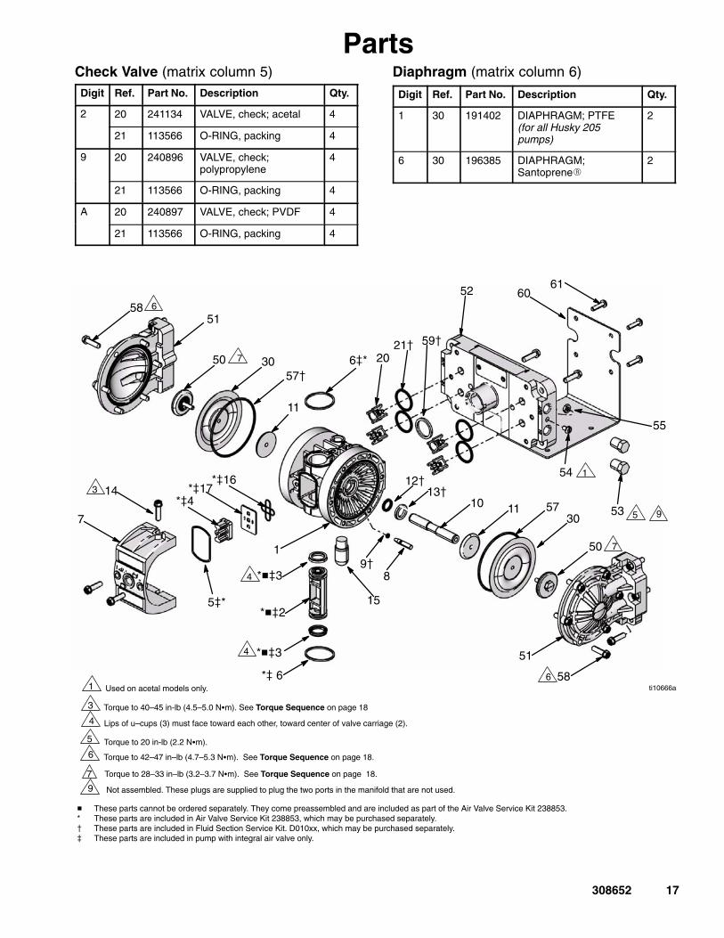
Used on acetal models only.
3 Torque to 40–45 in-lb (4.5–5.0 N�m). See Torque Sequence on page 18
4
Not assembled. These plugs are supplied to plug the two ports in the manifold that are not used.9
5 Torque to 20 in-lb (2.2 N�m).
4
21�20
1
*��2
1
89�
50
11
12�
710
50
51
51
52
54
55
30
30
57
57�
58
1
15
58
53 9
*��3
*� 6
*�4
5�*
6�*
5
ti10666a
11
143 13�
59�
*�17*�16
6061
Torque to 28–33 in–lb (3.2–3.7 N�m). See Torque Sequence on page 18.
6
7
7
7
6
� These parts cannot be ordered separately. They come preassembled and are included as part of the Air Valve Service Kit 238853.* These parts are included in Air Valve Service Kit 238853, which may be purchased separately.� These parts are included in Fluid Section Service Kit. D010xx, which may be purchased separately.� These parts are included in pump with integral air valve only.
Torque to 42–47 in–lb (4.7–5.3 N�m). See Torque Sequence on page 18.
*��3
4
6
Lips of u–cups (3) must face toward each other, toward center of valve carriage (2).
17308652
PartsCheck Valve (matrix column 5)Digit Ref. Part No. Description Qty.
2 20 241134 VALVE, check; acetal 4
21 113566 O-RING, packing 4
9 20 240896 VALVE, check;polypropylene
4
21 113566 O-RING, packing 4
A 20 240897 VALVE, check; PVDF 4
21 113566 O-RING, packing 4
Diaphragm (matrix column 6)
Digit Ref. Part No. Description Qty.
1 30 191402 DIAPHRAGM; PTFE(for all Husky 205pumps)
2
6 30 196385 DIAPHRAGM;Santoprene�
2
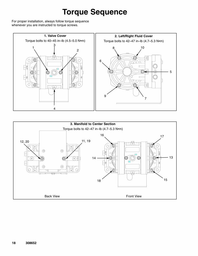
18 308652
Torque SequenceFor proper installation, always follow torque sequencewhenever you are instructed to torque screws.
1. Valve Cover
Torque bolts to 40–45 in–lb (4.5–5.0 N�m)2. Left/Right Fluid Cover
Torque bolts to 42–47 in–lb (4.7–5.3 N�m)
3. Manifold to Center Section
Torque bolts to 42–47 in–lb (4.7–5.3 N�m)
Front ViewBack View
12
3
4
9
6
7
5
108
11, 1912, 20
1314
15
16 17
18
19308652
Technical DataMaximum fluid working pressure 100 psi. . . . . . . . . . . . .
(0.7 MPa, 7 bar)Maximum/minimum air pressure 100 psi/20psi. . . . . .
(0.7 MPa, 7 bar)/(0.14 MPa, 1.4 bar)Maximum fluid flow 5.0 gpm (18.9 lpm). . . . . . . . . . . . . Maximum pump speed 320(dry) cycles per minute. . . .
250(wet) cycles per minuteVolume per stroke* 0.006 gal (23 cc). . . . . . . . . . . . . . . Volume per cycle* 0.012 gal (46 cc). . . . . . . . . . . . . . . . Maximum suction lift dry 8 to 10 ft. . . . . . . . . . . . . . . . . .
(2.5 to 3 m)Maximum size pumpable solids 0.06 in. (1.5 mm). . . . Maximum operating temperature 180� F (82� C). . . . . Maximum air consumption 9.0 scfm. . . . . . . . . . . . . . .
(0.252 m3/min.)Air inlet size** 1/4 npt(f) / 1/4 bsp(f). . . . . . . . . . . . . . . . . Fluid inlet size** 1/4 npt(f) / 1/4 bsp(f). . . . . . . . . . . . . . . Fluid outlet size** 1/4 npt(f) / 1/4 bsp(f). . . . . . . . . . . . . . Air exhaust port size** 1/4 npt(f) / 1/4 bsp(f). . . . . . . . .
WeightPolypropylene pump 2.0 lb (0.9 kg). . . . . . . . . . . . . . . Acetal pump 2.5 lb (1.1 kg). . . . . . . . . . . . . . . . . . . . . . PVDF pump 2.8 lb (1.3 kg). . . . . . . . . . . . . . . . . . . . . .
Wetted parts (housings, diaphragms, check valves)Polypropylene pump:Glass-filled polypropylene, PTFE, polypropylene,hastelloy
Acetal pump:Acetal with SST fibers, PTFE, acetal, hastelloy
PVDF pump:PVDF, PTFE, PVDF, hastelloy
Sound power level (pressure) (per ANSI STD S12.1)at 100 psi (0.7 MPa, 7 bar) 75.5 dBa. . . . . . . . . . . . . at 70 psi (0.49 MPa, 4.9 bar) 72.0 dBa. . . . . . . . . . . . at 40 psi (0.28 MPa, 2.8 bar) 68.2 dBa. . . . . . . . . . . .
Sound power level (intensity) (per ANSI STD S12.1)at 100 psi (0.7 MPa, 7 bar) 84.5 dBa. . . . . . . . . . . . . at 70 psi (0.49 MPa, 4.9 bar) 81.1 dBa. . . . . . . . . . . . at 40 psi (0.28 MPa, 2.8 bar) 76.6 dBa. . . . . . . . . . . .
* Volume per cycle may vary based on suction condition, discharge head, air pressure, and fluid.** Hybrid thread allows for either 1/4 npt or 1/4 bsp fitting.PVDF is a registered trademark of Atochem North America, Incorporated.Schrader Bellows is a registered trademark of Schrader Bellows.Santoprene� is a registered trademark of the Monsanto Company.
20 308652
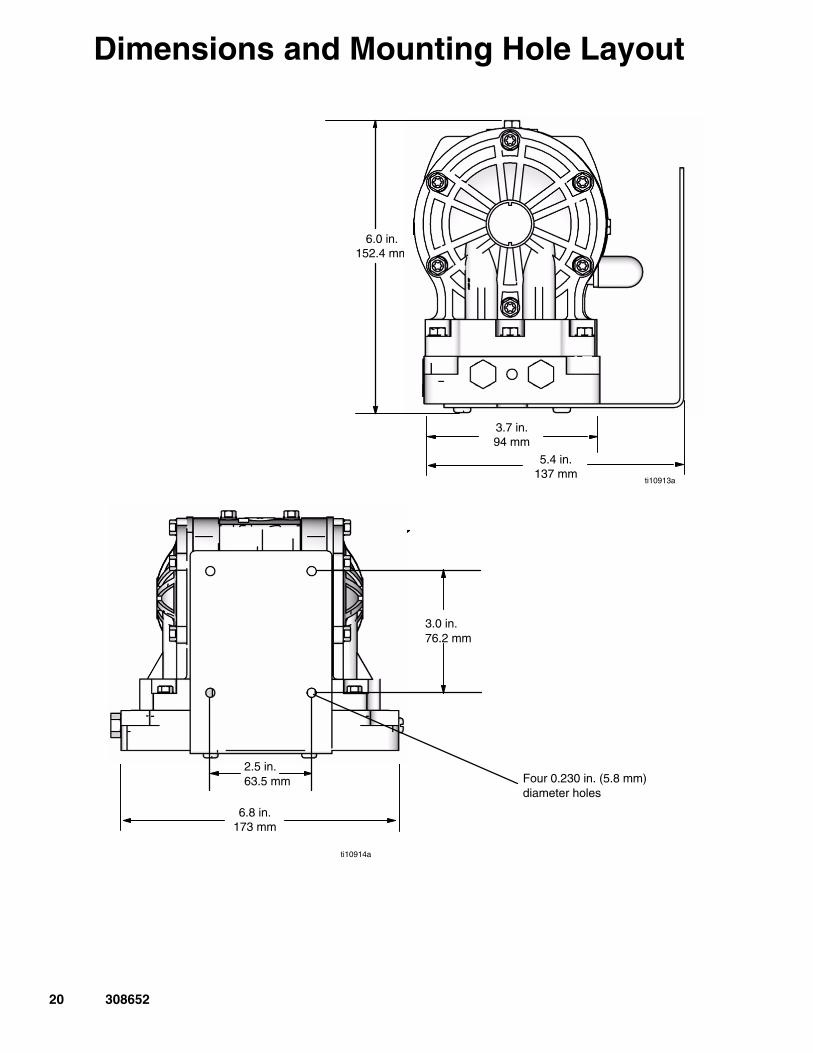
Dimensions and Mounting Hole Layout
6.0 in.152.4 mm
3.7 in.94 mm
Four 0.281 in.7.137 mm
diameter holes
6.8 in.173 mm
Four 0.175 in. x .85 in. deep4.445 mm x 21.59 mm deep
diameter holes
2.5 in.63.5 mm
3.0 in.76.2 mm
Four 0.230 in. (5.8 mm)diameter holes
ti10913a
ti10914a
5.4 in.137 mm
21308652
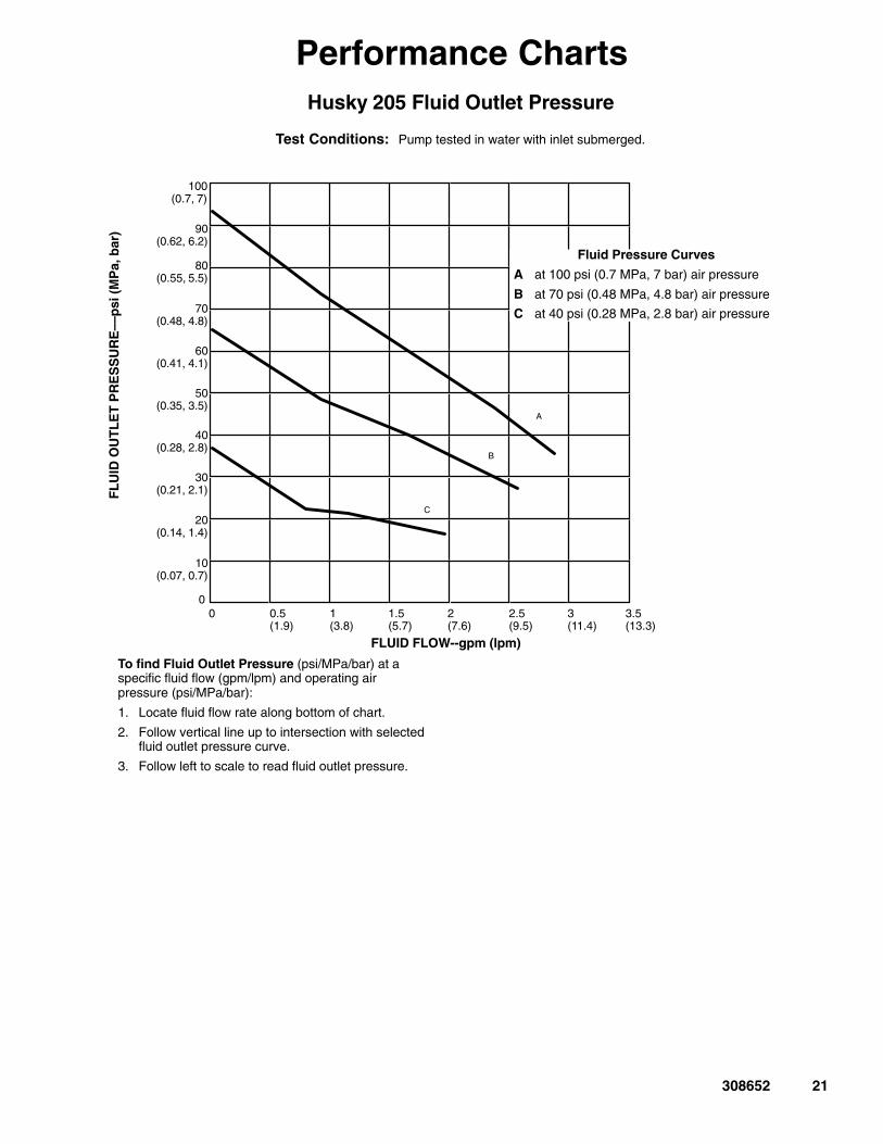
Performance ChartsHusky 205 Fluid Outlet Pressure
FLUID FLOW--gpm (lpm)
Test Conditions: Pump tested in water with inlet submerged.
To find Fluid Outlet Pressure (psi/MPa/bar) at aspecific fluid flow (gpm/lpm) and operating airpressure (psi/MPa/bar):
1. Locate fluid flow rate along bottom of chart.
2. Follow vertical line up to intersection with selectedfluid outlet pressure curve.
3. Follow left to scale to read fluid outlet pressure.
FL
UID
OU
TL
ET
PR
ES
SU
RE
––p
si (
MP
a, b
ar)
0.5(1.9)
2.5(9.5)
100(0.7, 7)
2(7.6)
A
B
C
80(0.55, 5.5)
60(0.41, 4.1)
40(0.28, 2.8)
20(0.14, 1.4)
1(3.8)
1.5(5.7)
90(0.62, 6.2)
70(0.48, 4.8)
50(0.35, 3.5)
30(0.21, 2.1)
10(0.07, 0.7)
00 3
(11.4)3.5(13.3)
Fluid Pressure Curves
A at 100 psi (0.7 MPa, 7 bar) air pressure
B at 70 psi (0.48 MPa, 4.8 bar) air pressure
C at 40 psi (0.28 MPa, 2.8 bar) air pressure
22 308652
Performance Charts
FLUID FLOW--gpm (lpm)
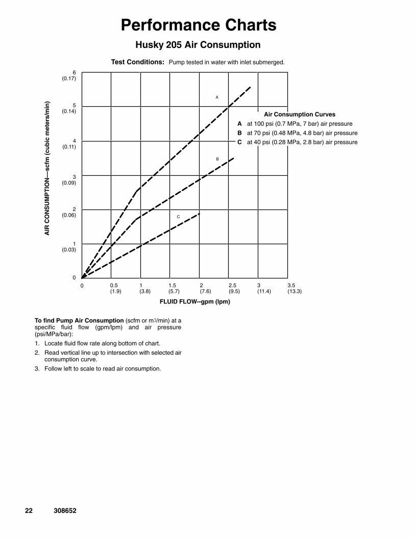
Test Conditions: Pump tested in water with inlet submerged.
AIR
CO
NS
UM
PT
ION
––sc
fm (
cub
ic m
eter
s/m
in)
To find Pump Air Consumption (scfm or m/min) at aspecific fluid flow (gpm/lpm) and air pressure(psi/MPa/bar):
1. Locate fluid flow rate along bottom of chart.
2. Read vertical line up to intersection with selected airconsumption curve.
3. Follow left to scale to read air consumption.
Husky 205 Air Consumption
0.5(1.9)
2.5(9.5)
3(0.09)
2(7.6)
1(3.8)
1.5(5.7)
5(0.14)
6(0.17)
4(0.11)
2(0.06)
B
C
A
1(0.03)
03(11.4)
3.5(13.3)
0
Air Consumption Curves
A at 100 psi (0.7 MPa, 7 bar) air pressure
B at 70 psi (0.48 MPa, 4.8 bar) air pressure
C at 40 psi (0.28 MPa, 2.8 bar) air pressure
23308652
Notes
24 308652
Graco WarrantiesGraco Standard Husky Pump WarrantyGraco warrants all equipment manufactured by Graco and bearing its name to be free from defects in material and workmanship on thedate of sale to the original purchaser for use. With the exception of any special, extended, or limited warranty published by Graco,Graco will, for a period of five years from the date of sale, repair or replace any part of the equipment determined by Graco to bedefective. This warranty applies only when the equipment is installed, operated and maintained in accordance with Graco’s writtenrecommendations.
This warranty does not cover, and Graco shall not be liable for general wear and tear, or any malfunction, damage or wear caused byfaulty installation, misapplication, abrasion, corrosion, inadequate or improper maintenance, negligence, accident, tampering, or sub-stitution of non-Graco component parts. Nor shall Graco be liable for malfunction, damage or wear caused by the incompatibility ofGraco equipment with structures, accessories, equipment or materials not supplied by Graco, or the improper design, manufacture,installation, operation or maintenance of structures, accessories, equipment or materials not supplied by Graco.
This warranty is conditioned upon the prepaid return of the equipment claimed to be defective to an authorized Graco distributor forverification of the claimed defect. If the claimed defect is verified, Graco will repair or replace free of charge any defective parts. Theequipment will be returned to the original purchaser transportation prepaid. If inspection of the equipment does not disclose any defectin material or workmanship, repairs will be made at a reasonable charge, which charges may include the costs of parts, labor, andtransportation.
THIS WARRANTY IS EXCLUSIVE, AND IS IN LIEU OF ANY OTHER WARRANTIES, EXPRESS OR IMPLIED, INCLUDING BUTNOT LIMITED TO WARRANTY OF MERCHANTABILITY OR WARRANTY OF FITNESS FOR A PARTICULAR PURPOSE.
Graco’s sole obligation and buyer’s sole remedy for any breach of warranty shall be as set forth above. The buyer agrees that no otherremedy (including, but not limited to, incidental or consequential damages for lost profits, lost sales, injury to person or property, or anyother incidental or consequential loss) shall be available. Any action for breach of warranty must be brought within six years of the dateof sale.
Graco makes no warranty, and disclaims all implied warranties of merchantability and fitness for a particular purpose in connectionwith accessories, equipment, materials or components sold but not manufactured by Graco. These items sold, but not manufacturedby Graco (such as electric motors, switches, hose, etc.), are subject to the warranty, if any, of their manufacturer. Graco will providepurchaser with reasonable assistance in making any claim for breach of these warranties.
In no event will Graco be liable for indirect, incidental, special or consequential damages resulting from Graco supplying equipmenthereunder, or the furnishing, performance, or use of any products or other goods sold hereto, whether due to a breach of contract,breach of warranty, the negligence of Graco, or otherwise.
FOR GRACO CANADA CUSTOMERSThe parties acknowledge that they have required that the present document, as well as all documents, notices and legal proceedingsentered into, given or instituted pursuant hereto or relating directly or indirectly hereto, be drawn up in English. Les parties reconnais-sent avoir convenu que la rédaction du présente document sera en Anglais, ainsi que tous documents, avis et procédures judiciairesexécutés, donnés ou intentés à la suite de ou en rapport, directement ou indirectement, avec les procedures concernées.
Extended Product WarrantyGraco warrants all Husky 205, 307, 515, 716, 1040, 1590, 2150, and 3275 air valve center sections to be free from defects in materialand workmanship for a period of fifteen years from date installed in service by the original purchaser. Normal wear of items such aspackings or seals are not considered to be defects in material and workmanship.
Five years Graco will provide parts and labor.Six to Fifteen years Graco will replace defective parts only.
Graco InformationFor the latest information about Graco products, visit www.graco.com.
TO PLACE AN ORDER, contact your Graco distributor, or call one of the following numbersto identify the distributor closest to you: 1–800–328–0211 Toll Free, 612–623–6921, 612–378–3505 Fax
All written and visual data contained in this document reflects the latest product information available at the time of publication.Graco reserves the right to make changes at any time without notice.
For patent information, see www.graco.com/patents.
Original instructions. This manual contains English. MM 308652
Graco Headquarters: MinneapolisInternational Offices: Belgium, China, Japan, Korea
������������� ����������������������������������������������������� ��
������� ����� ����� ���� ��� ����� ����������� �������� ��� �������� �� � ! �""��
www.graco.comRevision ZAA September 2012