hts2030smd – temperature and relative humidity … · based on a unique capacitive cell for...
TRANSCRIPT
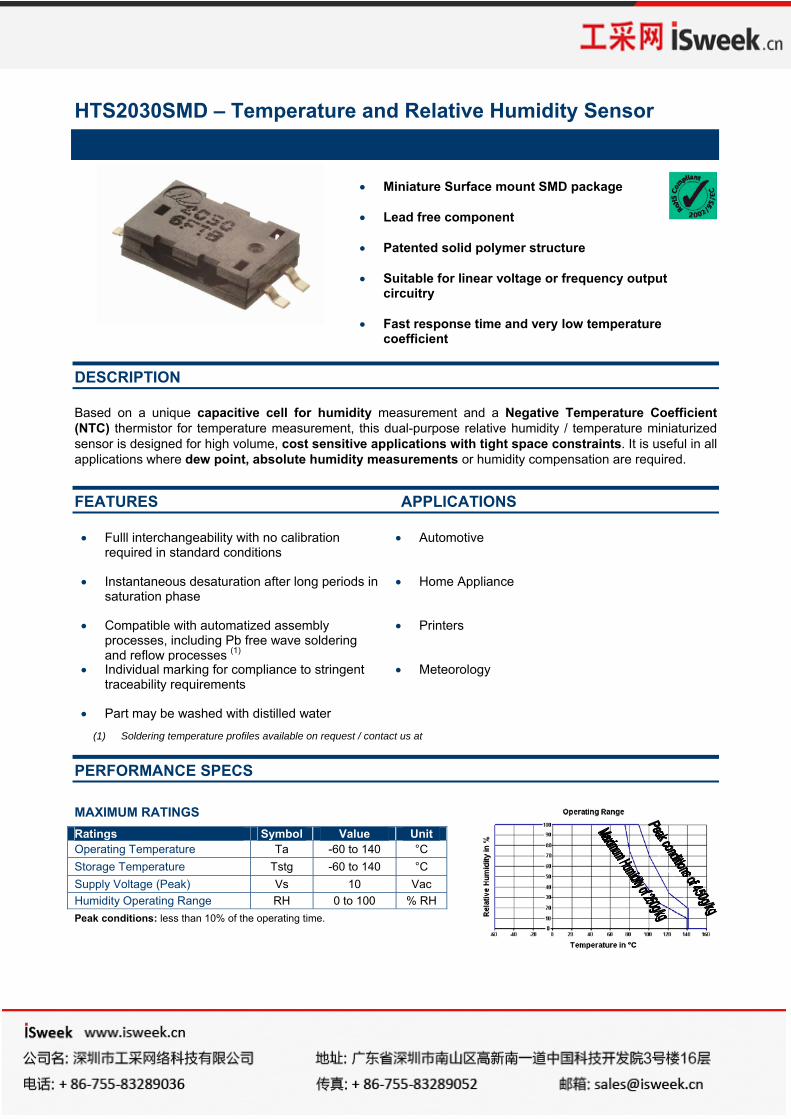
HTS2030SMD – Temperature and Relative Humidity Sensor
• Miniature Surface mount SMD package • Lead free component • Patented solid polymer structure • Suitable for linear voltage or frequency output
circuitry • Fast response time and very low temperature
coefficient
DESCRIPTION
Based on a unique capacitive cell for humidity measurement and a Negative Temperature Coefficient (NTC) thermistor for temperature measurement, this dual-purpose relative humidity / temperature miniaturized sensor is designed for high volume, cost sensitive applications with tight space constraints. It is useful in all applications where dew point, absolute humidity measurements or humidity compensation are required. FEATURES APPLICATIONS
• Fulll interchangeability with no calibration required in standard conditions
• Automotive
• Instantaneous desaturation after long periods in saturation phase
• Home Appliance
• Compatible with automatized assembly processes, including Pb free wave soldering and reflow processes (1)
• Printers
• Individual marking for compliance to stringent traceability requirements
• Meteorology
• Part may be washed with distilled water
(1) Soldering temperature profiles available on request / contact us at
PERFORMANCE SPECS
MAXIMUM RATINGS
Peak conditions: less than 10% of the operating time.
Ratings Symbol Value Unit Operating Temperature Ta -60 to 140 °C Storage Temperature Tstg -60 to 140 °C Supply Voltage (Peak) Vs 10 Vac Humidity Operating Range RH 0 to 100 % RH
HTS2030SMD – Temperature and Relative Humidity Sensor
ELECTRICAL CHARACTERISTICS (Ta=25°C, measurement frequency @10kHz unless otherwise noted)
(1) Tighter specification available on request
TYPICAL PERFORMANCE CURVES
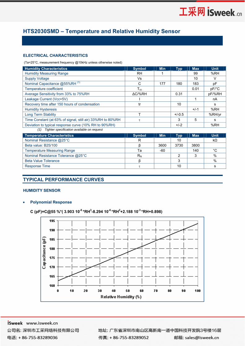
HUMIDITY SENSOR • Polynomial Response
C (pF)=C@55 %*( 3.903 10-8 *RH3-8.294 10-6 *RH2+2.188 10-3 *RH+0.898)
Humidity Characteristics Symbol Min Typ Max Unit Humidity Measuring Range RH 1 99 %RH Supply Voltage Vs 10 V Nominal Capacitance @55%RH (1) C 177 180 183 pF Temperature coefficient Tcc 0.01 pF/°C Average Sensitivity from 33% to 75%RH ΔC/%RH 0.31 pF/%RH Leakage Current (Vcc=5V) I 1 nA Recovery time after 150 hours of condensation tr 10 s Humidity Hysteresis +/-1 %RH Long Term Stability T +/-0.5 %RH/yr Time Constant (at 63% of signal, still air) 33%RH to 80%RH τ 3 5 s Deviation to typical response curve (10% RH to 90%RH) +/-2 %RH
Temperature Characteristics Symbol Min Typ Max Unit Nominal Resistance @25°C R 10 kΩ Beta value: B25/100 β 3600 3730 3800 Temperature Measuring Range Ta -60 140 °C Nominal Resistance Tolerance @25°C RN 2 3 % Beta Value Tolerance β 3 % Response Time τ 10 s
HTS2030SMD – Temperature and Relative Humidity Sensor
• Typical Response Look-Up Table (polynomial reference curve) @10kHz/1V
RH (%) 0 5 10 15 20 25 30 35 40 45 50
Cp (pF) 161.6 163.6 165.4 167.2 169.0 170.7 172.3 173.9 175.5 177.0 178.5
RH (%) 55 60 65 70 75 80 85 90 95 100
Cp (pF) 180 181.4 182.9 184.3 185.7 187.2 188.6 190.1 191.6 193.1
• Reverse Polynomial Response
RH (%) = -3.4656 10+3*X3+1.0732 10+4*X2-1.0457 10+4*X+3.2459 10+3 With X = C(read) / C@55%RH
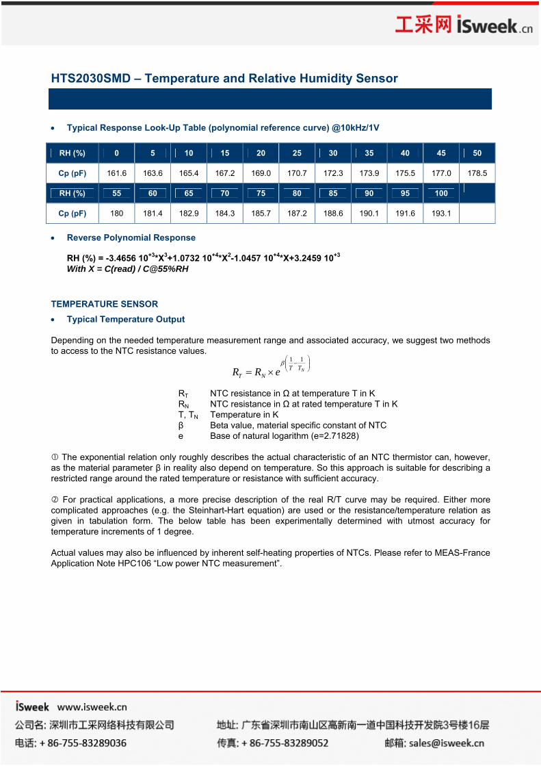
TEMPERATURE SENSOR • Typical Temperature Output Depending on the needed temperature measurement range and associated accuracy, we suggest two methods to access to the NTC resistance values.
RT NTC resistance in Ω at temperature T in K RN NTC resistance in Ω at rated temperature T in K T, TN Temperature in K β Beta value, material specific constant of NTC e Base of natural logarithm (e=2.71828)
The exponential relation only roughly describes the actual characteristic of an NTC thermistor can, however,
as the material parameter β in reality also depend on temperature. So this approach is suitable for describing a restricted range around the rated temperature or resistance with sufficient accuracy.
For practical applications, a more precise description of the real R/T curve may be required. Either more complicated approaches (e.g. the Steinhart-Hart equation) are used or the resistance/temperature relation as given in tabulation form. The below table has been experimentally determined with utmost accuracy for temperature increments of 1 degree. Actual values may also be influenced by inherent self-heating properties of NTCs. Please refer to MEAS-France Application Note HPC106 “Low power NTC measurement”.
⎟⎟⎠
⎞⎜⎜⎝
⎛−
×= NTTNT eRR
11β
HTS2030SMD – Temperature and Relative Humidity Sensor
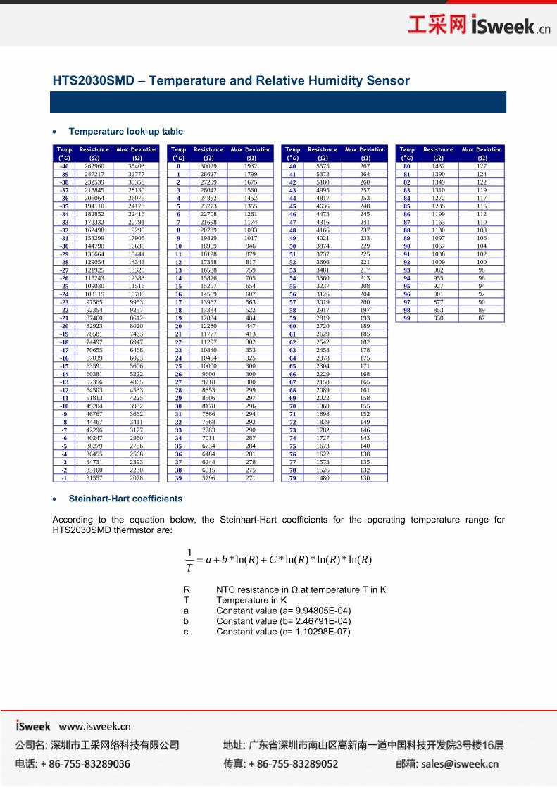
• Temperature look-up table
• Steinhart-Hart coefficients According to the equation below, the Steinhart-Hart coefficients for the operating temperature range for HTS2030SMD thermistor are:
)ln(*)ln(*)ln(*)ln(*1 RRRCRbaT
++=
R NTC resistance in Ω at temperature T in K T Temperature in K a Constant value (a= 9.94805E-04) b Constant value (b= 2.46791E-04) c Constant value (c= 1.10298E-07)
Temp Resistance Max Deviation Temp Resistance Max Deviation Temp Resistance Max Deviation Temp Resistance Max Deviation(°C) (Ω) (Ω) (°C) (Ω) (Ω) (°C) (Ω) (Ω) (°C) (Ω) (Ω)-40 262960 35403 0 30029 1932 40 5575 267 80 1432 127-39 247217 32777 1 28627 1799 41 5373 264 81 1390 124-38 232539 30358 2 27299 1675 42 5180 260 82 1349 122-37 218845 28130 3 26042 1560 43 4995 257 83 1310 119-36 206064 26075 4 24852 1452 44 4817 253 84 1272 117-35 194110 24178 5 23773 1355 45 4636 248 85 1235 115-34 182852 22416 6 22708 1261 46 4473 245 86 1199 112-33 172332 20791 7 21698 1174 47 4316 241 87 1163 110-32 162498 19290 8 20739 1093 48 4166 237 88 1130 108-31 153299 17905 9 19829 1017 49 4021 233 89 1097 106-30 144790 16636 10 18959 946 50 3874 229 90 1067 104-29 136664 15444 11 18128 879 51 3737 225 91 1038 102-28 129054 14343 12 17338 817 52 3606 221 92 1009 100-27 121925 13325 13 16588 759 53 3481 217 93 982 98-26 115243 12383 14 15876 705 54 3360 213 94 955 96-25 109030 11516 15 15207 654 55 3237 208 95 927 94-24 103115 10705 16 14569 607 56 3126 204 96 901 92-23 97565 9953 17 13962 563 57 3019 200 97 877 90-22 92354 9257 18 13384 522 58 2917 197 98 853 89-21 87460 8612 19 12834 484 59 2819 193 99 830 87-20 82923 8020 20 12280 447 60 2720 189-19 78581 7463 21 11777 413 61 2629 185-18 74497 6947 22 11297 382 62 2542 182-17 70655 6468 23 10840 353 63 2458 178-16 67039 6023 24 10404 325 64 2378 175-15 63591 5606 25 10000 300 65 2304 171-14 60381 5222 26 9600 300 66 2229 168-13 57356 4865 27 9218 300 67 2158 165-12 54503 4533 28 8853 299 68 2089 161-11 51813 4225 29 8506 297 69 2022 158-10 49204 3932 30 8178 296 70 1960 155-9 46767 3662 31 7866 294 71 1898 152-8 44467 3411 32 7568 292 72 1839 149-7 42296 3177 33 7283 290 73 1782 146-6 40247 2960 34 7011 287 74 1727 143-5 38279 2756 35 6734 284 75 1673 140-4 36455 2568 36 6484 281 76 1622 138-3 34731 2393 37 6244 278 77 1573 135-2 33100 2230 38 6015 275 78 1526 132-1 31557 2078 39 5796 271 79 1480 130
HTS2030SMD – Temperature and Relative Humidity Sensor
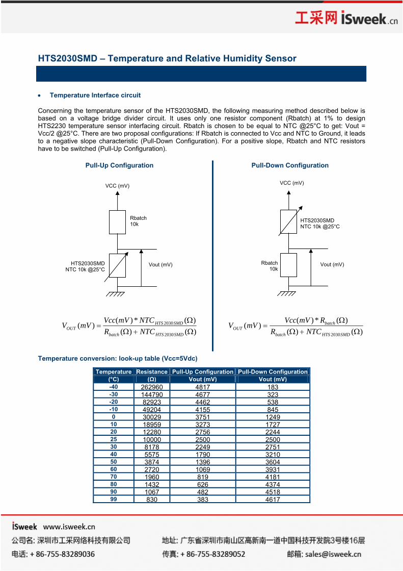
• Temperature Interface circuit Concerning the temperature sensor of the HTS2030SMD, the following measuring method described below is based on a voltage bridge divider circuit. It uses only one resistor component (Rbatch) at 1% to design HTS2230 temperature sensor interfacing circuit. Rbatch is chosen to be equal to NTC @25°C to get: Vout = Vcc/2 @25°C. There are two proposal configurations: If Rbatch is connected to Vcc and NTC to Ground, it leads to a negative slope characteristic (Pull-Down Configuration). For a positive slope, Rbatch and NTC resistors have to be switched (Pull-Up Configuration).
Pull-Up Configuration Pull-Down Configuration
)()()(*)(
)(2030
2030
Ω+ΩΩ
=SMDHTSbatch
SMDHTSOUT NTCR
NTCmVVccmVV
)()()(*)(
)(2030 Ω+ΩΩ
=SMDHTSbatch
batchOUT NTCR
RmVVccmVV
Temperature conversion: look-up table (Vcc=5Vdc)
Temperature Resistance Pull-Up Configuration Pull-Down Configuration (°C) (Ω) Vout (mV) Vout (mV) -40 262960 4817 183-30 144790 4677 323-20 82923 4462 538-10 49204 4155 8450 30029 3751 1249
10 18959 3273 172720 12280 2756 224425 10000 2500 250030 8178 2249 275140 5575 1790 321050 3874 1396 360460 2720 1069 393170 1960 819 418180 1432 626 437490 1067 482 451899 830 383 4617
Vout (mV)
HTS2030SMD NTC 10k @25°C
Rbatch
10k
VCC (mV)
HTS2030SMD NTC 10k @25°C
Vout (mV)
VCC (mV)
Rbatch 10k
HTS2030SMD – Temperature and Relative Humidity Sensor
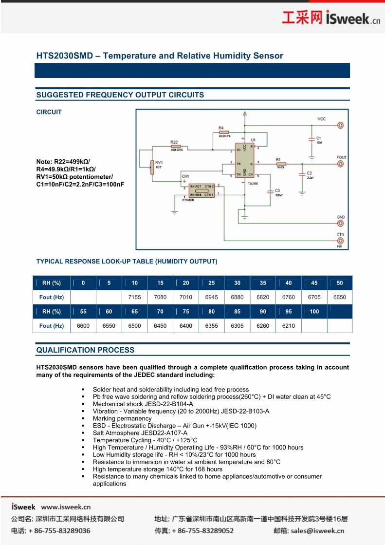
SUGGESTED FREQUENCY OUTPUT CIRCUITS
CIRCUIT Note: R22=499kΩ/ R4=49.9kΩ/R1=1kΩ/ RV1=50kΩ potentiometer/ C1=10nF/C2=2.2nF/C3=100nF
TYPICAL RESPONSE LOOK-UP TABLE (HUMIDITY OUTPUT)
RH (%) 0 5 10 15 20 25 30 35 40 45 50
Fout (Hz) 7155 7080 7010 6945 6880 6820 6760 6705 6650
RH (%) 55 60 65 70 75 80 85 90 95 100
Fout (Hz) 6600 6550 6500 6450 6400 6355 6305 6260 6210
QUALIFICATION PROCESS
HTS2030SMD sensors have been qualified through a complete qualification process taking in account many of the requirements of the JEDEC standard including:
Solder heat and solderability including lead free process Pb free wave soldering and reflow soldering process(260°C) + DI water clean at 45°C Mechanical shock JESD-22-B104-A Vibration - Variable frequency (20 to 2000Hz) JESD-22-B103-A Marking permanency ESD - Electrostatic Discharge – Air Gun +-15kV(IEC 1000) Salt Atmosphere JESD22-A107-A Temperature Cycling - 40°C / +125°C High Temperature / Humidity Operating Life - 93%RH / 60°C for 1000 hours Low Humidity storage life - RH < 10%/23°C for 1000 hours Resistance to immersion in water at ambient temperature and 80°C High temperature storage 140°C for 168 hours Resistance to many chemicals linked to home appliances/automotive or consumer
applications
HTS2030SMD – Temperature and Relative Humidity Sensor
ENVIRONMENTAL AND RECYCLING
HTS2030SMD sensors are lead free components and are compatible with Pb Free soldering processes. HTS2030SMD sensors are free from Cr (6+), Cd and Hg. SOLDERING INSTRUCTIONS
We recommend taking specific attention to soldering conditions to get the best performance of MEAS-France sensors. See Application Note. To get it, please contact: PACKAGE OUTLINE
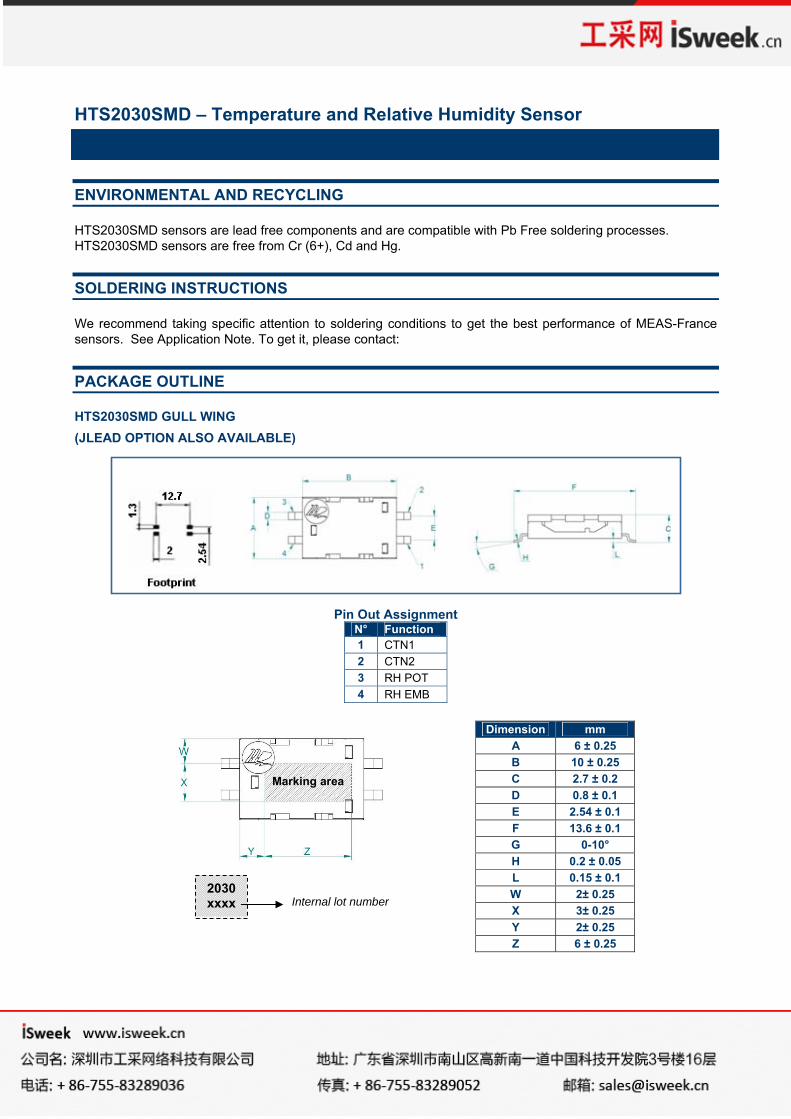
HTS2030SMD GULL WING (JLEAD OPTION ALSO AVAILABLE)
Pin Out Assignment
N° Function 1 CTN1 2 CTN2 3 RH POT 4 RH EMB
Dimension mm A 6 ± 0.25 B 10 ± 0.25 C 2.7 ± 0.2 D 0.8 ± 0.1 E 2.54 ± 0.1 F 13.6 ± 0.1 G 0-10° H 0.2 ± 0.05 L 0.15 ± 0.1 W 2± 0.25 X 3± 0.25 Y 2± 0.25 Z 6 ± 0.25
2030 xxxx Internal lot number
Marking area
HTS2030SMD – Temperature and Relative Humidity Sensor
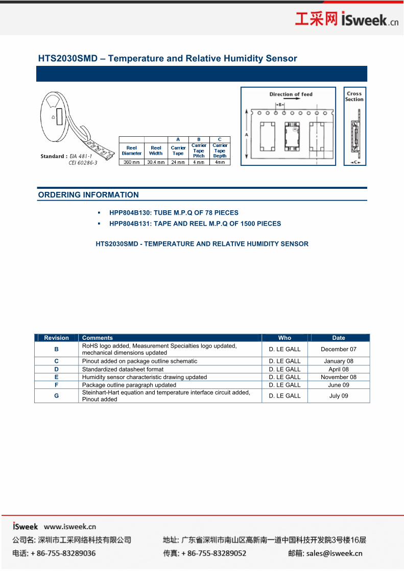
ORDERING INFORMATION
HPP804B130: TUBE M.P.Q OF 78 PIECES HPP804B131: TAPE AND REEL M.P.Q OF 1500 PIECES
HTS2030SMD - TEMPERATURE AND RELATIVE HUMIDITY SENSOR
Revision Comments Who Date
B RoHS logo added, Measurement Specialties logo updated, mechanical dimensions updated D. LE GALL December 07
C Pinout added on package outline schematic D. LE GALL January 08 D Standardized datasheet format D. LE GALL April 08 E Humidity sensor characteristic drawing updated D. LE GALL November 08 F Package outline paragraph updated D. LE GALL June 09
G Steinhart-Hart equation and temperature interface circuit added, Pinout added D. LE GALL July 09