hrv heat reclaim ventilation - internet - uk | daikin · · 2018-05-01hrv heat reclaim...
TRANSCRIPT
VAM-FA Series
VKM-GM Series
VKM-G Series
HRVHeat ReclaimVentilation
EPCE05-44A 30/09/05 8:37 Page 1
MOV91822_EPCe05-44A
Cyan Magenta Yellow Black

EPCE05-44A 30/09/05 8:37 Page 2
MOV91822_EPCe05-44A
Cyan Magenta Yellow Black
INTRODUCTION
GENERAL HRV FEATURESEnergy EfficiencyDesign FlexibilityClean Air
VKM FEATURESEnergy EfficiencyDesign Flexibility
LINE-UP
CONTROL SYSTEMSIndividual Control SystemsCentralised Control Systems
SPECIFICATIONSVAM-FAVKM-GMVKM-G
OPTIONS
4
6679
101011
12
131316
18181920
21
c o n t e n t s
Table of Contents
p. 3
EPCE05-44A 30/09/05 8:37 Page 3
MOV91822_EPCe05-44A
Cyan Magenta Yellow Black
p. 4D a i k i ni n t r o d u c t i o n
Daikin has a worldwide reputation based on over 70 years’
experience in the successful manufacture of high quality air
conditioning equipment for industrial, commercial and
residential use.
Daikin Europe N.V.
Enhancing the present - safeguarding the future
Throughout the last 50 years or so the basic building blocks of life - air, water and the earth - have been
systematically subjected to increasing levels of pollution with little regard to their potentially devastating
effects on future generations.
Recently however, concern has grown regarding climate changes, acid rain, water and air pollution and
the constant degradation of Earth’s natural resources. The very technology that created these problems is
now being harnessed to halt and reverse them. Depletion of the ozone layer and global warming have
been highlighted and are now being addressed. Government legislation prohibiting the use of toxic
substances and the generation of pollutants has slowed down the destruction of the environment.
Daikin Europe is proud to have been pro active in this respect, closely following its Japanese parent in
implementing policies that have often pre-empted official legislative codes and directives. As a result, a
culture of “environmental management” has since 2001, played a key role in the company’s day to day
activities and development strategies.
Top management commitment is reflected in the establishment of a number of action plans, which are
now strictly observed and implemented throughout the Daikin Group.
Environmental Consciousness
EPCE05-44A 30/09/05 8:37 Page 4
MOV91822_EPCe05-44A
Cyan Magenta Yellow Black
p. 5
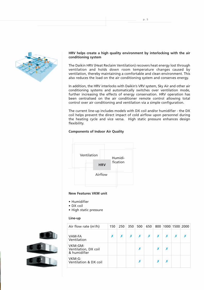
HRV helps create a high quality environment by interlocking with the airconditioning system
The Daikin HRV (Heat Reclaim Ventilation) recovers heat energy lost throughventilation and holds down room temperature changes caused byventilation, thereby maintaining a comfortable and clean environment. Thisalso reduces the load on the air conditioning system and conserves energy.
In addition, the HRV interlocks with Daikin’s VRV system, Sky Air and other airconditioning systems and automatically switches over ventilation mode,further increasing the effects of energy conservation. HRV operation hasbeen centralised on the air conditioner remote control allowing totalcontrol over air conditioning and ventilation via a simple configuration.
The current line-up includes models with DX coil and/or humidifier - the DXcoil helps prevent the direct impact of cold airflow upon personnel duringthe heating cycle and vice versa. High static pressure enhances designflexibility.
Components of Indoor Air Quality
New Features VKM unit
• Humidifier• DX coil• High static pressure
Line-up
Air flow rate (m3/h) 150 250 350 500 650 800 1000 1500 2000
VAM-FAVentilation
VKM-GM:Ventilation, DX coil& humidifier
VKM-G:Ventilation & DX coil
VentilationHumidi-fication
Airflow
HRV
EPCE05-44A 30/09/05 8:37 Page 5
MOV91822_EPCe05-44A
Cyan Magenta Yellow Black
1. ENERGY EFFICIENCY
• Over 30 % Size ReductionUse of the high efficiency paper (HEP) element and optimized design of the fan and airflowpassages have resulted in matchless compactness without detriment to the 28% or so reductionin air conditioning load achieved by previous models. A reduction of up to 40mm in heightallows the main unit to fit easily into limited spaces such as ceilingsOn average 28 % air conditioning load reduction (maximum 40 %):- 20% by operating in total heat exchange mode (in comparison with normal ventilation fans)- a further 6 % by auto-ventilation mode changeover switching- a further 2 % by pre-cool, pre-heat control (reduces air conditioning load by not running the
HRV while air is still clean soon after the air conditioner is switched on.)Note: the values mentioned above may vary according to weather and other environmental conditions at the location of the unit’s
installation
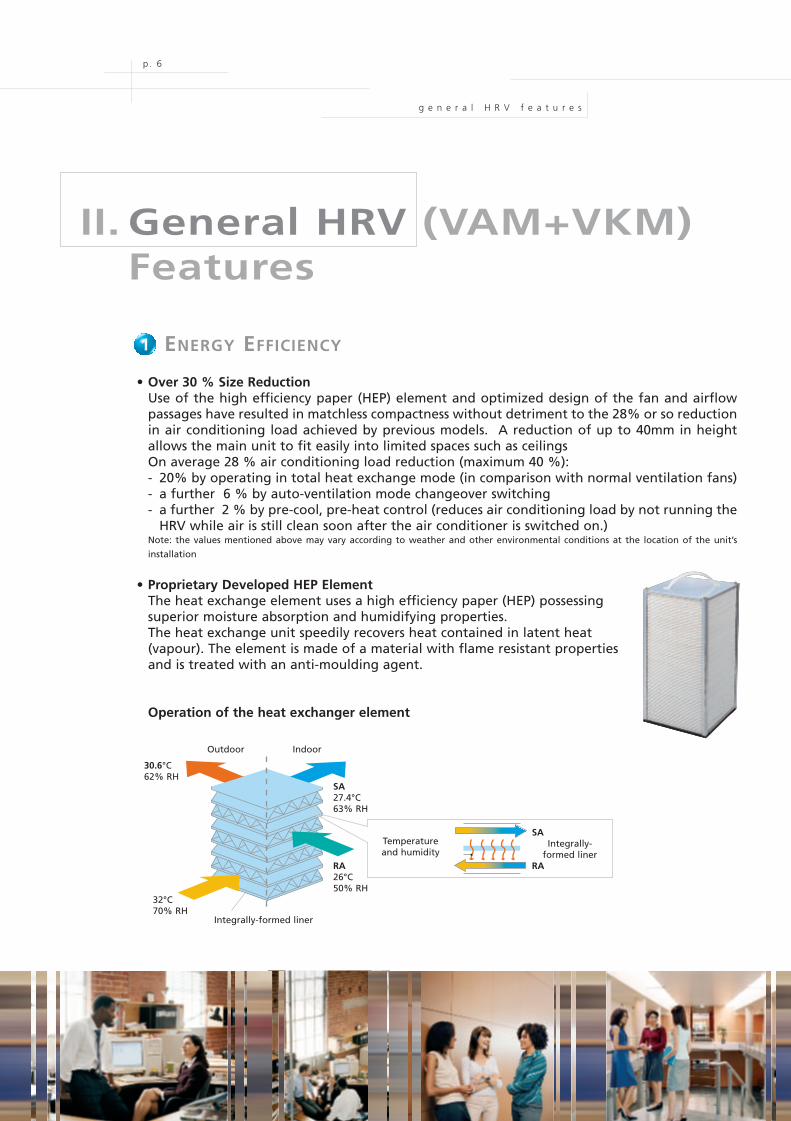
• Proprietary Developed HEP ElementThe heat exchange element uses a high efficiency paper (HEP) possessingsuperior moisture absorption and humidifying properties.The heat exchange unit speedily recovers heat contained in latent heat(vapour). The element is made of a material with flame resistant propertiesand is treated with an anti-moulding agent.
Operation of the heat exchanger element
p. 6
II. General HRV (VAM+VKM)Features
g e n e r a l H R V f e a t u r e s
1
Outdoor Indoor
SA27.4°C63% RH
RA26°C50% RH
30.6°C62% RH
32°C70% RH
Integrally-formed liner
Temperatureand humidity
SAIntegrally-
formed linerRA
EPCE05-44A 30/09/05 8:37 Page 6
MOV91822_EPCe05-44A
Cyan Magenta Yellow Black
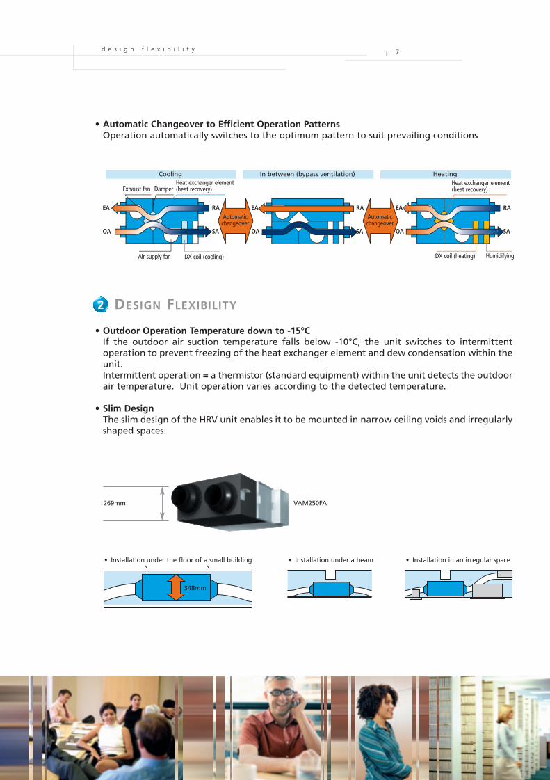
• Automatic Changeover to Efficient Operation PatternsOperation automatically switches to the optimum pattern to suit prevailing conditions
2. DESIGN FLEXIBILITY
• Outdoor Operation Temperature down to -15°CIf the outdoor air suction temperature falls below -10°C, the unit switches to intermittentoperation to prevent freezing of the heat exchanger element and dew condensation within theunit.Intermittent operation = a thermistor (standard equipment) within the unit detects the outdoorair temperature. Unit operation varies according to the detected temperature.
• Slim DesignThe slim design of the HRV unit enables it to be mounted in narrow ceiling voids and irregularlyshaped spaces.
d e s i g n f l e x i b i l i t y p . 7
2
Cooling In between (bypass ventilation) Heating
Automaticchangeover
Automaticchangeover
Exhaust fan DamperHeat exchanger element(heat recovery)
Heat exchanger element(heat recovery)
DX coil (cooling)Air supply fan DX coil (heating) Humidifying
EA
OA
EA
OA
RA
SA
RA
SA
EA
OA
RA
SA
269mm VAM250FA
• Installation under the floor of a small building • Installation under a beam • Installation in an irregular space
348mm
EPCE05-44A 30/09/05 8:37 Page 7
MOV91822_EPCe05-44A
Cyan Magenta Yellow Black
d e s i g n f l e x i b i l i t y
p . 8
• Simple Design and ConstructionThe unit can be installed either horizontally or vertically in accordance with the conditions ofthe location.A 450mm square inspection hatch enables maintenance and heat exchange elementreplacement to be performed with ease.
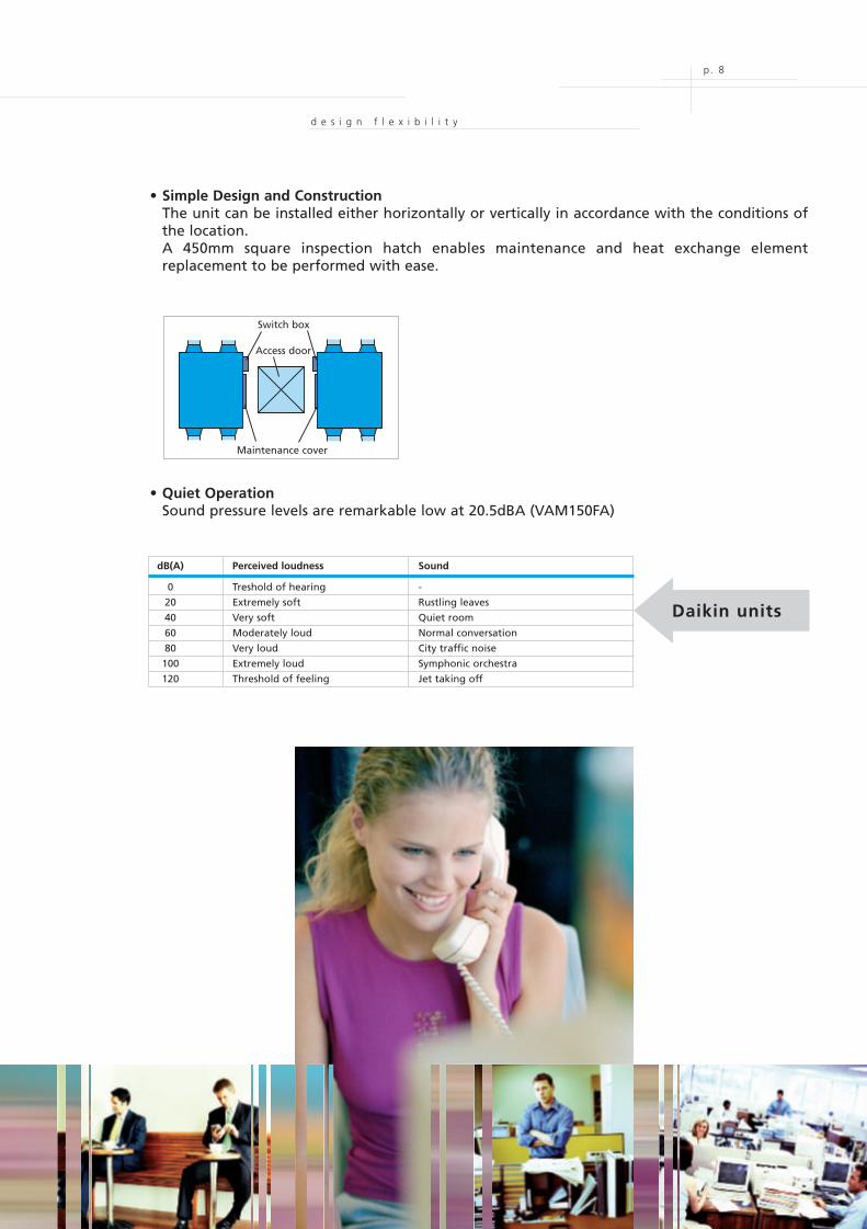
• Quiet OperationSound pressure levels are remarkable low at 20.5dBA (VAM150FA)
Switch box
Access door
Maintenance cover
dB(A) Perceived loudness Sound
0 Treshold of hearing -
20 Extremely soft Rustling leaves
40 Very soft Quiet room
60 Moderately loud Normal conversation
80 Very loud City traffic noise
100 Extremely loud Symphonic orchestra
120 Threshold of feeling Jet taking off
Daikin units
EPCE05-44A 30/09/05 8:37 Page 8
MOV91822_EPCe05-44A
Cyan Magenta Yellow Black
p. 9c l e a n a i r
3. CLEAN AIR
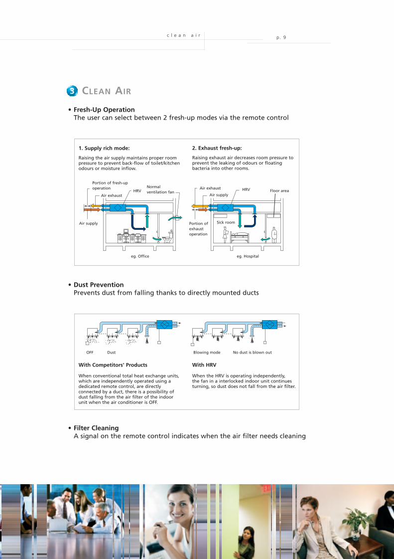
• Fresh-Up OperationThe user can select between 2 fresh-up modes via the remote control
• Dust PreventionPrevents dust from falling thanks to directly mounted ducts
• Filter CleaningA signal on the remote control indicates when the air filter needs cleaning
3
With Competitors' Products
When conventional total heat exchange units,which are independently operated using adedicated remote control, are directlyconnected by a duct, there is a possibility ofdust falling from the air filter of the indoorunit when the air conditioner is OFF.
Raising the air supply maintains proper roompressure to prevent back-flow of toilet/kitchenodours or moisture inflow.
Raising exhaust air decreases room pressure toprevent the leaking of odours or floatingbacteria into other rooms.
OFF
Air supply Portion ofexhaustoperation
Portion of fresh-upoperation
Air exhaust
Normalventilation fan
Air exhaust
Air supplyHRV HRV
Dust Blowing mode No dust is blown out
With HRV
When the HRV is operating independently,the fan in a interlocked indoor unit continuesturning, so dust does not fall from the air filter.
eg. Office eg. Hospital
Sick room
Floor area
1. Supply rich mode: 2. Exhaust fresh-up:
EPCE05-44A 30/09/05 8:37 Page 9
MOV91822_EPCe05-44A
Cyan Magenta Yellow Black
p. 10
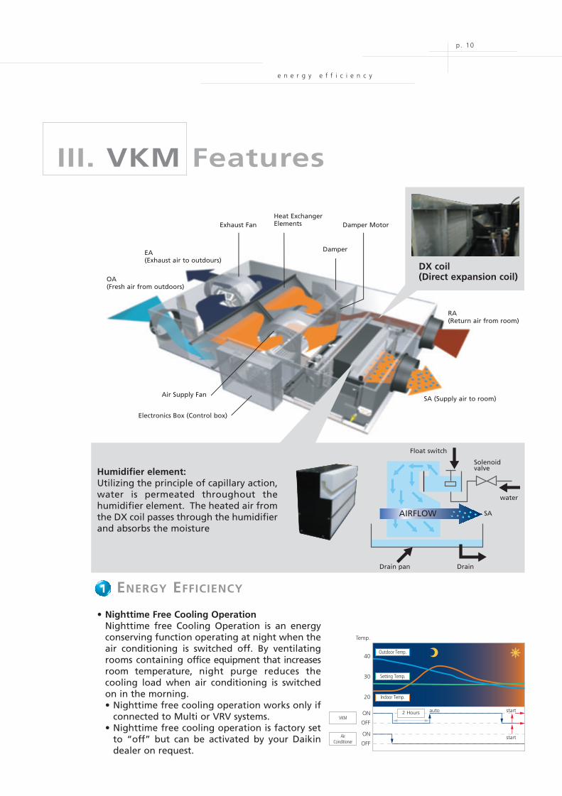
III. VKM Features
Exhaust FanHeat ExchangerElements Damper Motor
DamperEA(Exhaust air to outdours)
OA(Fresh air from outdoors)
Air Supply Fan
Electronics Box (Control box)
SA (Supply air to room)
RA(Return air from room)
DX coil(Direct expansion coil)
e n e r g y e f f i c i e n c y
Humidifier element:Utilizing the principle of capillary action,water is permeated throughout thehumidifier element. The heated air fromthe DX coil passes through the humidifierand absorbs the moisture
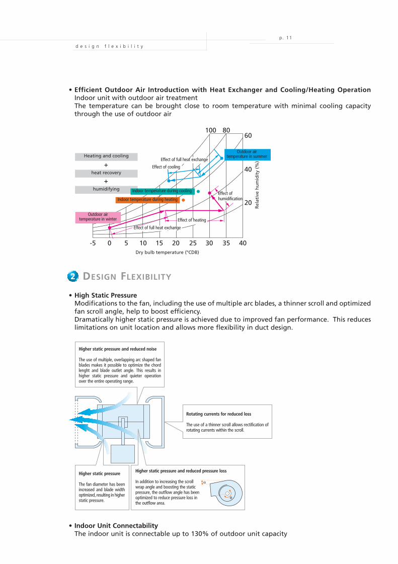
1. ENERGY EFFICIENCY
• Nighttime Free Cooling OperationNighttime free Cooling Operation is an energyconserving function operating at night when theair conditioning is switched off. By ventilatingrooms containing office equipment that increasesroom temperature, night purge reduces thecooling load when air conditioning is switchedon in the morning.• Nighttime free cooling operation works only if
connected to Multi or VRV systems.• Nighttime free cooling operation is factory set
to “off” but can be activated by your Daikindealer on request.
1
Float switch
Solenoidvalve
water
SA
Drain pan Drain
AIRFLOW
40
30
20
ON
OFF
ON
OFF
Temp.
2 Hours auto start
start
VKM
AirConditioner
Indoor Temp.
Outdoor Temp.
Setting Temp.
EPCE05-44A 30/09/05 8:37 Page 10
MOV91822_EPCe05-44A
Cyan Magenta Yellow Black
p. 11
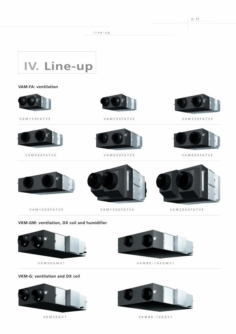
• Efficient Outdoor Air Introduction with Heat Exchanger and Cooling/Heating OperationIndoor unit with outdoor air treatmentThe temperature can be brought close to room temperature with minimal cooling capacitythrough the use of outdoor air
2. DESIGN FLEXIBILITY
• High Static PressureModifications to the fan, including the use of multiple arc blades, a thinner scroll and optimizedfan scroll angle, help to boost efficiency.Dramatically higher static pressure is achieved due to improved fan performance. This reduceslimitations on unit location and allows more flexibility in duct design.
2
Effect of full heat exchangeEffect of heat ng
-5 0 5 10 15 20 25 30 35 40
100 8060
40
20
+
+
Heating and cooling
heat recovery
humidifying
Outdoor airtemperature in winter
Outdoor airtemperature in summer
Effect of full heat exchange
Effect of cooling
Effect ofhumidification
Indoor temperature during cooling
Indoor temperature during heating
Effect of heating
Effect of full heat exchange
Dry bulb temperature (°CDB)R
elat
ive
hu
mid
ity
(%)
α
θ
Higher static pressure and reduced noise
The use of multiple, overlapping arc shaped fanblades makes it possible to optimize the chordlenght and blade outlet angle. This results inhigher static pressure and quieter operationover the entire operating range.
Rotating currents for reduced loss
The use of a thinner scroll allows rectification ofrotating currents within the scroll.
Higher static pressure
The fan diameter has beenincreased and blade widthoptimized, resulting in higherstatic pressure.
Higher static pressure and reduced pressure loss
In addition to increasing the scrollwrap angle and boosting the staticpressure, the outflow angle has beenoptimized to reduce pressure loss inthe outflow area.
d e s i g n f l e x i b i l i t y
• Indoor Unit ConnectabilityThe indoor unit is connectable up to 130% of outdoor unit capacity
EPCE05-44A 30/09/05 8:37 Page 11
MOV91822_EPCe05-44A
Cyan Magenta Yellow Black
p. 12
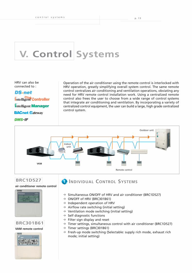
IV. Line-up
l i n e - u p
V A M 1 5 0 F A 7 V E V A M 2 5 0 F A 7 V E
V A M 8 0 0 F A 7 V E
V A M 1 5 0 0 F A 7 V E V A M 2 0 0 0 F A 7 V E
V A M 3 5 0 F A 7 V E
V A M 5 0 0 F A 7 V E V A M 6 5 0 F A 7 V E
V A M 1 0 0 0 F A 7 V E
V K M 8 0 - 1 0 0 G M V 1V K M 5 0 G M V 1
V K M 5 0 G V 1
VAM-FA: ventilation
VKM-GM: ventilation, DX coil and humidifier
VKM-G: ventilation and DX coil
V K M 8 0 - 1 0 0 G V 1
EPCE05-44A 30/09/05 8:37 Page 12
MOV91822_EPCe05-44A
Cyan Magenta Yellow Black
c o n t r o l s y s t e m s p. 13
V. Control Systems
Operation of the air conditioner using the remote control is interlocked withHRV operation, greatly simplifying overall system control. The same remotecontrol centralizes air conditioning and ventilation operations, obviating anyneed for HRV remote control installation work. Using a centralized remotecontrol also frees the user to choose from a wide range of control systemsthat integrate air conditioning and ventilation. By incorporating a variety ofcentralized control equipment, the user can build a large, high grade centralizedcontrol system.
Outdoor unit
Indoorunit
Remote control
VKM
[iPU]
BRC1D527
BRC301B61
INDIVIDUAL CONTROL SYSTEMS
9 Simultaneous ON/OFF of HRV and air conditioner (BRC1D527)9 ON/OFF of HRV (BRC301B61)9 Independent operation of HRV9 Airflow rate switching (initial setting)9 Ventilation mode switching (initial setting)9 Self diagnostic functions9 Filter sign display and reset9 Timer settings, simultaneous control with air conditioner (BRC1D527)9 Timer settings (BRC301B61)9 Fresh-up mode switching (Selectable: supply rich mode, exhaust rich
mode; initial setting)
1
HRV can also beconnected to :
air conditioner remote control
VAM remote control
EPCE05-44A 30/09/05 8:37 Page 13
MOV91822_EPCe05-44A
Cyan Magenta Yellow Black
p. 14
i n d i v i d u a l c o n t r o l s y s t e m s
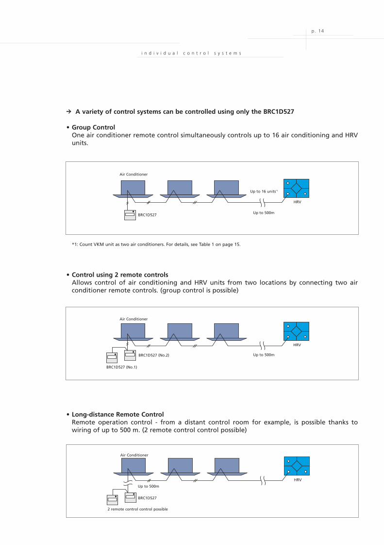
9 A variety of control systems can be controlled using only the BRC1D527
• Group ControlOne air conditioner remote control simultaneously controls up to 16 air conditioning and HRVunits.
*1: Count VKM unit as two air conditioners. For details, see Table 1 on page 15.
• Control using 2 remote controlsAllows control of air conditioning and HRV units from two locations by connecting two airconditioner remote controls. (group control is possible)
• Long-distance Remote ControlRemote operation control - from a distant control room for example, is possible thanks towiring of up to 500 m. (2 remote control control possible)
Air Conditioner
Up to 16 units*1
Up to 500m
HRV
BRC1D527
BRC1D527 (No.2)
BRC1D527 (No.1)
Air Conditioner
Up to 500m
HRV
BRC1D527
2 remote control control possible
Air Conditioner
Up to 500m
HRV
EPCE05-44A 30/09/05 8:37 Page 14
MOV91822_EPCe05-44A
Cyan Magenta Yellow Black
p. 15
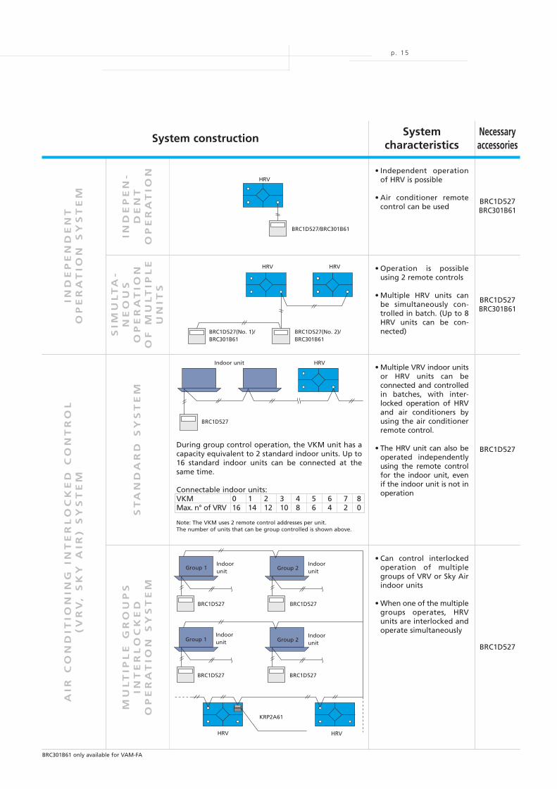
• Independent operationof HRV is possible
• Air conditioner remotecontrol can be used
BRC1D527BRC301B61
BRC1D527BRC301B61
BRC1D527
BRC1D527
• Operation is possibleusing 2 remote controls
• Multiple HRV units canbe simultaneously con-trolled in batch. (Up to 8HRV units can be con-nected)
IND
EP
EN
-D
EN
TO
PE
RA
TIO
N
SIM
UL
TA
-N
EO
US
OP
ER
AT
ION
OF
MU
LT
IPL
EU
NIT
S
IND
EP
EN
DE
NT
OP
ER
AT
ION
SY
ST
EM
• Can control interlockedoperation of multiplegroups of VRV or Sky Airindoor units
• When one of the multiplegroups operates, HRVunits are interlocked andoperate simultaneously
ST
AN
DA
RD
SY
ST
EM
AIR
CO
ND
ITIO
NIN
G I
NT
ER
LO
CK
ED
CO
NT
RO
L(V
RV
, S
KY
AIR
) S
YS
TE
M
MU
LT
IPL
E G
RO
UP
SIN
TE
RL
OC
KE
DO
PE
RA
TIO
N S
YS
TE
M
HRV
BRC1D527/BRC301B61
BRC1D527(No. 1)/BRC301B61
BRC1D527
BRC1D527
Indoorunit
BRC1D527(No. 2)/BRC301B61
HRV
Indoor unit
HRV
HRV
Group 1
BRC1D527
Indoorunit
Group 2
BRC1D527
KRP2A61
Indoorunit
Group 2
BRC1D527
IndoorunitGroup 1
HRV HRV
• Multiple VRV indoor unitsor HRV units can beconnected and controlledin batches, with inter-locked operation of HRVand air conditioners byusing the air conditionerremote control.
• The HRV unit can also beoperated independentlyusing the remote controlfor the indoor unit, evenif the indoor unit is not inoperation
During group control operation, the VKM unit has acapacity equivalent to 2 standard indoor units. Up to16 standard indoor units can be connected at thesame time.
Connectable indoor units:VKM 0 1 2 3 4 5 6 7 8Max. n° of VRV 16 14 12 10 8 6 4 2 0
Note: The VKM uses 2 remote control addresses per unit.The number of units that can be group controlled is shown above.
Systemcharacteristics
Necessaryaccessories
System construction
BRC301B61 only available for VAM-FA
EPCE05-44A 30/09/05 8:37 Page 15
MOV91822_EPCe05-44A
Cyan Magenta Yellow Black
c e n t r a l i s e d c o n t r o l s y s t e m s
p. 16
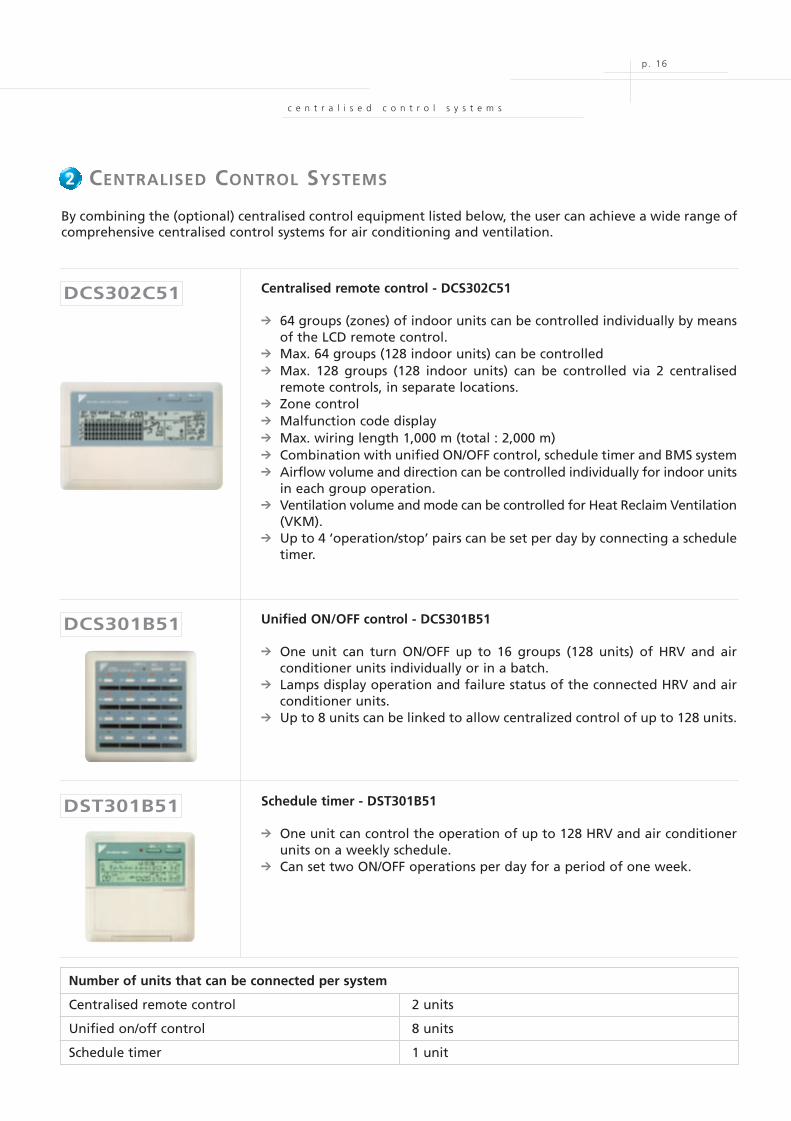
2. CENTRALISED CONTROL SYSTEMS
Centralised remote control - DCS302C51
9 64 groups (zones) of indoor units can be controlled individually by meansof the LCD remote control.
9 Max. 64 groups (128 indoor units) can be controlled9 Max. 128 groups (128 indoor units) can be controlled via 2 centralised
remote controls, in separate locations.9 Zone control9 Malfunction code display9 Max. wiring length 1,000 m (total : 2,000 m)9 Combination with unified ON/OFF control, schedule timer and BMS system9 Airflow volume and direction can be controlled individually for indoor units
in each group operation.9 Ventilation volume and mode can be controlled for Heat Reclaim Ventilation
(VKM).9 Up to 4 ‘operation/stop’ pairs can be set per day by connecting a schedule
timer.
By combining the (optional) centralised control equipment listed below, the user can achieve a wide range ofcomprehensive centralised control systems for air conditioning and ventilation.
Unified ON/OFF control - DCS301B51
9 One unit can turn ON/OFF up to 16 groups (128 units) of HRV and airconditioner units individually or in a batch.
9 Lamps display operation and failure status of the connected HRV and airconditioner units.
9 Up to 8 units can be linked to allow centralized control of up to 128 units.
Schedule timer - DST301B51
9 One unit can control the operation of up to 128 HRV and air conditionerunits on a weekly schedule.
9 Can set two ON/OFF operations per day for a period of one week.
DST301B51
DCS301B51
DCS302C51
Number of units that can be connected per system
Centralised remote control 2 units
Unified on/off control 8 units
Schedule timer 1 unit
2
EPCE05-44A 30/09/05 8:37 Page 16
MOV91822_EPCe05-44A
Cyan Magenta Yellow Black
p. 17
Indoor unit
Indoor unit
BRC1D527 BRC1D527
Zon
e 2
Zon
e 1
BRC1D527
HRV
HRV
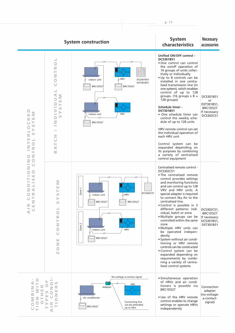
Centralised remote control -DCS302C51• The centralised remote
control provides settingsand monitoring functionsand can control up to 128VRV and HRV units. Aspecial adapter is requiredto connect Sky Air to thecentralised line.
• Control is possible in 3different patterns: indi-vidual, batch or zone
• Multiple groups can becontrolled within the samezone
• Multiple HRV units canbe operated indepen-dently
• System without air condi-tioning or HRV remotecontrols can be constructed
• Control system can beexpanded depending onrequirements by combi-ning a variety of centra-lised control systems
ZO
NE
C
ON
TR
OL
S
YS
TE
M
AIR
C
ON
DIT
IO
NIN
G IN
TE
RL
OC
KE
DC
EN
TR
AL
IS
ED
C
ON
TR
OL
S
YS
TE
MC
OM
BIN
A-
TIO
N W
IT
HO
TH
ER
TY
PE
S O
FA
IR
C
ON
DI-
TIO
NE
RS
• Simultaneous operationof HRVs and air condi-tioners is possible viaBRC1D527
• Use of the HRV remotecontrol enables to changesettings or operate HRVsindependently
Systemcharacteristics
Necessaryaccessories
System construction
Unified ON/OFF control -DCS301B51• One control can control
the on/off operation of16 groups of units collec-tively or individually
• Up to 8 controls can beinstalled in one centra-lised transmission line (inone system), which enablescontrol of up to 128groups. (16 groups x 8 =128 groups)
Schedule timer -DST301B51• One schedule timer can
control the weekly sche-dule of up to 128 units
HRV remote control can setthe individual operation ofeach HRV unit
Control system can beexpanded depending onits purposes by combininga variety of centralisedcontrol equipment
BA
TC
H /
IN
DIV
ID
UA
L C
ON
TR
OL
SY
ST
EM
BRC1D527BRC1D527
BRC1D527
DCS301B51DST301B51
Indoor unit
Indoor unit
HRV
HRV
BRC1D527
Connecting linecan be extendedup to 50m
No-voltage a-contact signal
HRV
Air conditioner
Adapter
DCS302C51
Connectionadapter
(no-voltage-a-contact-
signal)
DCS302C51,BRC1D527
If necessary:DCS301B51,DST301B51
DCS301B51or
DST301B51,BRC1D527
If necessary:DCS302C51
EPCE05-44A 30/09/05 8:37 Page 17
MOV91822_EPCe05-44A
Cyan Magenta Yellow Black
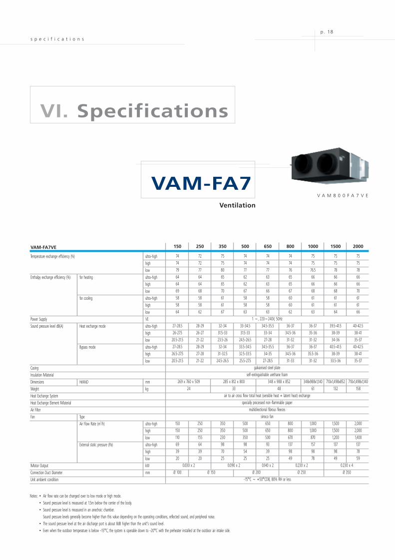
150 250 350 500 650 800 1000 1500 2000
74 72 75 74 74 74 75 75 75
74 72 75 74 74 74 75 75 75
79 77 80 77 77 76 76.5 78 78
64 64 65 62 63 65 66 66 66
64 64 65 62 63 65 66 66 66
69 68 70 67 66 67 68 68 70
58 58 61 58 58 60 61 61 61
58 58 61 58 58 60 61 61 61
64 62 67 63 63 62 63 64 66
1 ~, 220~240V, 50Hz
27-28.5 28-29 32-34 33-34.5 34.5-35.5 36-37 36-37 39.5-41.5 40-42.5
26-27.5 26-27 31.5-33 31.5-33 33-34 34.5-36 35-36 38-39 38-41
20.5-21.5 21-22 23.5-26 24.5-26.5 27-28 31-32 31-32 34-36 35-37
27-28.5 28-29 32-34 33.5-34.5 34.5-35.5 36-37 36-37 40.5-41.5 40-42.5
26.5-27.5 27-28 31-32.5 32.5-33.5 34-35 34.5-36 35.5-36 38-39 38-41
20.5-21.5 21-22 24.5-26.5 25.5-27.5 27-28.5 31-33 31-32 33.5-36 35-37
galvanised steel plate
self-extinguishable urethane foam
269 x 760 x 509 285 x 812 x 800 348 x 988 x 852 348x988x1,140 710x1,498x852 710x1,498x1,140
24 33 48 61 132 158
air to air cross flow total heat (sensible heat + latent heat) exchange
specially processed non-flammable paper
multidirectional fibrous fleeces
sirroco fan
150 250 350 500 650 800 1,000 1,500 2,000
150 250 350 500 650 800 1,000 1,500 2,000
110 155 230 350 500 670 870 1,200 1,400
69 64 98 98 93 137 157 137 137
39 39 70 54 39 98 98 98 78
20 20 25 25 25 49 78 49 59
0.030 x 2 0.090 x 2 0.140 x 2 0.230 x 2 0.230 x 4
Ø 100 Ø 150 Ø 200 Ø 250 Ø 350
-15°C ~ +50°CDB, 80% RH or less
p. 18
VI. Specifications
VAM-FA7
VAM-FA7VE
Temperature exchange efficiency (%) ultra-high
high
low
Enthalpy exchange efficiency (%) for heating ultra-high
high
low
for cooling ultra-high
high
low
Power Supply VE
Sound pressure level dB(A) Heat exchange mode ultra-high
high
low
Bypass mode ultra-high
high
low
Casing
Insulation Material
Dimensions HxWxD mm
Weight kg
Heat Exchange System
Heat Exchange Element Material
Air Filter
Fan Type
Air Flow Rate (m3/h) ultra-high
high
low
External static pressure (Pa) ultra-high
high
low
Motor Output kW
Connection Duct Diameter mm
Unit ambient condition
Notes: • Air flow rate can be changed over to low mode or high mode.• Sound pressure level is measured at 1.5m below the center of the body. • Sound pressure level is measured in an anechoic chamber.
Sound pressure levels generally become higher than this value depending on the operating conditions, reflected sound, and peripheral noise.• The sound pressure level at the air discharge port is about 8dB higher than the unit's sound level.• Even when the outdoor temperature is below -15°C, the system is operable down to -20°C with the preheater installed at the outdoor air intake side.
s p e c i f i c a t i o n s
V A M 8 0 0 F A 7 V E
Ventilation
EPCE05-44A 30/09/05 8:37 Page 18
MOV91822_EPCe05-44A
Cyan Magenta Yellow Black
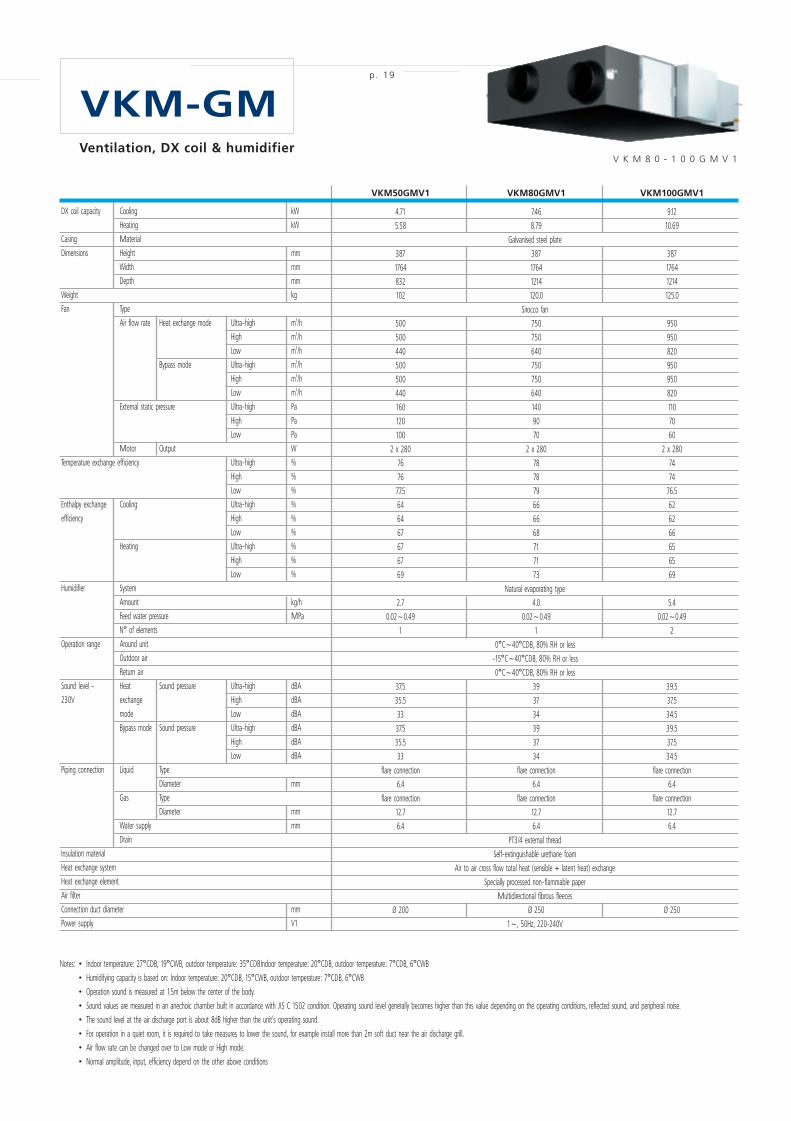
VKM50GMV1 VKM80GMV1 VKM100GMV1
4.71 7.46 9.12
5.58 8.79 10.69
Galvanised steel plate
387 387 387
1764 1764 1764
832 1214 1214
102 120.0 125.0
Sirocco fan
500 750 950
500 750 950
440 640 820
500 750 950
500 750 950
440 640 820
160 140 110
120 90 70
100 70 60
2 x 280 2 x 280 2 x 280
76 78 74
76 78 74
77.5 79 76.5
64 66 62
64 66 62
67 68 66
67 71 65
67 71 65
69 73 69
Natural evaporating type
2.7 4.0 5.4
0.02~0.49 0.02~0.49 0.02~0.49
1 1 2
0°C~40°CDB, 80% RH or less
-15°C~40°CDB, 80% RH or less
0°C~40°CDB, 80% RH or less
37.5 39 39.5
35.5 37 37.5
33 34 34.5
37.5 39 39.5
35.5 37 37.5
33 34 34.5
flare connection flare connection flare connection
6.4 6.4 6.4
flare connection flare connection flare connection
12.7 12.7 12.7
6.4 6.4 6.4
PT3/4 external thread
Self-extinguishable urethane foam
Air to air cross flow total heat (sensible + latent heat) exchange
Specially processed non-flammable paper
Multidirectional fibrous fleeces
Ø 200 Ø 250 Ø 250
1~, 50Hz, 220-240V
DX coil capacity Cooling kW
Heating kW
Casing Material
Dimensions Height mm
Width mm
Depth mm
Weight kg
Fan Type
Air flow rate Heat exchange mode Ultra-high m3/h
High m3/h
Low m3/h
Bypass mode Ultra-high m3/h
High m3/h
Low m3/h
External static pressure Ultra-high Pa
High Pa
Low Pa
Motor Output W
Temperature exchange efficiency Ultra-high %
High %
Low %
Enthalpy exchange Cooling Ultra-high %
efficiency High %
Low %
Heating Ultra-high %
High %
Low %
Humidifier System
Amount kg/h
Feed water pressure MPa
N° of elements
Operation range Around unit
Outdoor air
Return air
Sound level - Heat Sound pressure Ultra-high dBA
230V exchange High dBA
mode Low dBA
Bypass mode Sound pressure Ultra-high dBA
High dBA
Low dBA
Piping connection Liquid Type
Diameter mm
Gas Type
Diameter mm
Water supply mm
Drain
Insulation material
Heat exchange system
Heat exchange element
Air filter
Connection duct diameter mm
Power supply V1
VKM-GMp. 19
Notes: • Indoor temperature: 27°CDB, 19°CWB, outdoor temperature: 35°CDBIndoor temperature: 20°CDB, outdoor temperature: 7°CDB, 6°CWB
• Humidifying capacity is based on: Indoor temperature: 20°CDB, 15°CWB, outdoor temperature: 7°CDB, 6°CWB
• Operation sound is measured at 1.5m below the center of the body.
• Sound values are measured in an anechoic chamber built in accordance with JIS C 1502 condition. Operating sound level generally becomes higher than this value depending on the operating conditions, reflected sound, and peripheral noise.
• The sound level at the air discharge port is about 8dB higher than the unit’s operating sound.
• For operation in a quiet room, it is required to take measures to lower the sound, for example install more than 2m soft duct near the air discharge grill.
• Air flow rate can be changed over to Low mode or High mode.
• Normal amplitude, input, efficiency depend on the other above conditions
V K M 8 0 - 1 0 0 G M V 1Ventilation, DX coil & humidifier
EPCE05-44A 30/09/05 8:37 Page 19
MOV91822_EPCe05-44A
Cyan Magenta Yellow Black
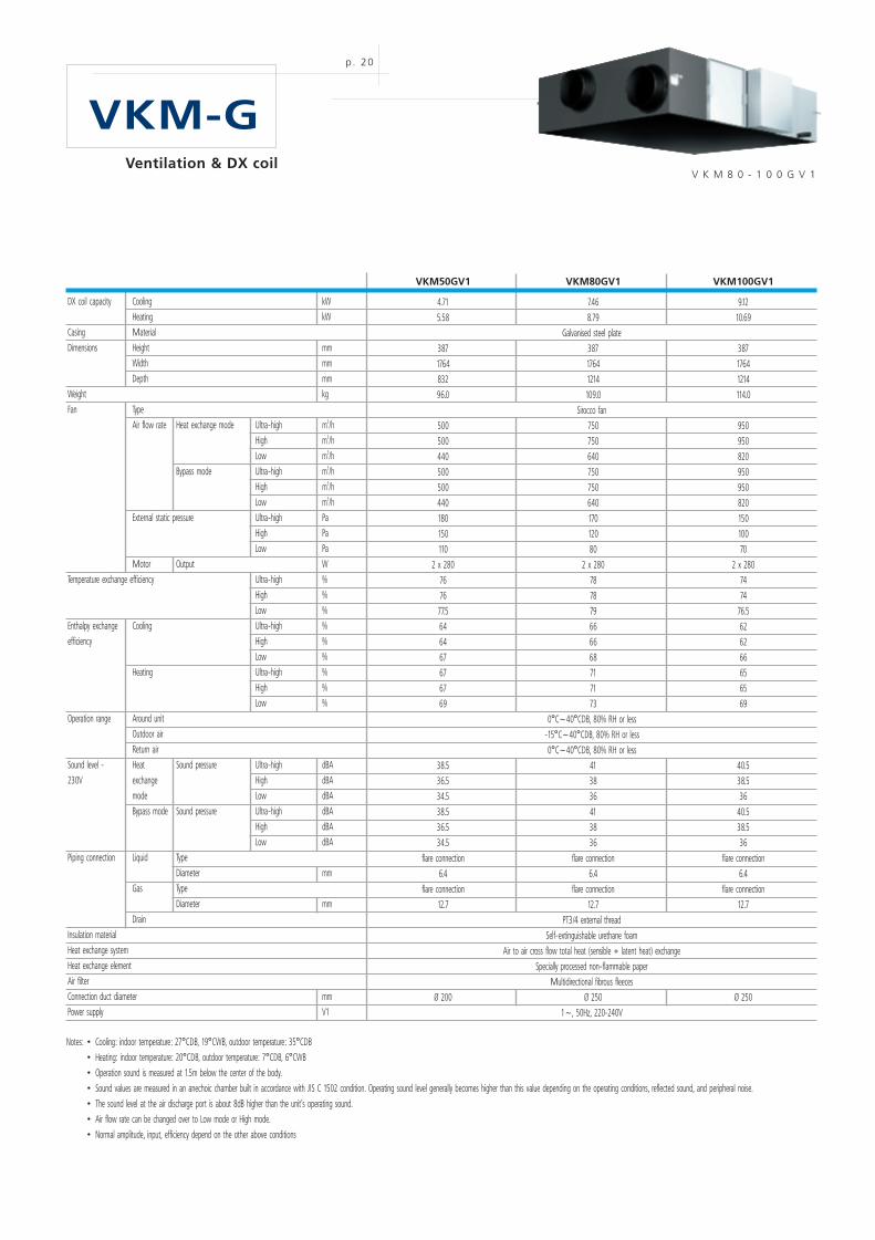
Notes: • Cooling: indoor temperature: 27°CDB, 19°CWB, outdoor temperature: 35°CDB
• Heating: indoor temperature: 20°CDB, outdoor temperature: 7°CDB, 6°CWB
• Operation sound is measured at 1.5m below the center of the body.
• Sound values are measured in an anechoic chamber built in accordance with JIS C 1502 condition. Operating sound level generally becomes higher than this value depending on the operating conditions, reflected sound, and peripheral noise.
• The sound level at the air discharge port is about 8dB higher than the unit’s operating sound.
• Air flow rate can be changed over to Low mode or High mode.
• Normal amplitude, input, efficiency depend on the other above conditions
p. 20
VKM-G
VKM50GV1 VKM80GV1 VKM100GV1
4.71 7.46 9.12
5.58 8.79 10.69
Galvanised steel plate
387 387 387
1764 1764 1764
832 1214 1214
96.0 109.0 114.0
Sirocco fan
500 750 950
500 750 950
440 640 820
500 750 950
500 750 950
440 640 820
180 170 150
150 120 100
110 80 70
2 x 280 2 x 280 2 x 280
76 78 74
76 78 74
77.5 79 76.5
64 66 62
64 66 62
67 68 66
67 71 65
67 71 65
69 73 69
0°C~40°CDB, 80% RH or less
-15°C~40°CDB, 80% RH or less
0°C~40°CDB, 80% RH or less
38.5 41 40.5
36.5 38 38.5
34.5 36 36
38.5 41 40.5
36.5 38 38.5
34.5 36 36
flare connection flare connection flare connection
6.4 6.4 6.4
flare connection flare connection flare connection
12.7 12.7 12.7
PT3/4 external thread
Self-extinguishable urethane foam
Air to air cross flow total heat (sensible + latent heat) exchange
Specially processed non-flammable paper
Multidirectional fibrous fleeces
Ø 200 Ø 250 Ø 250
1~, 50Hz, 220-240V
DX coil capacity Cooling kW
Heating kW
Casing Material
Dimensions Height mm
Width mm
Depth mm
Weight kg
Fan Type
Air flow rate Heat exchange mode Ultra-high m3/h
High m3/h
Low m3/h
Bypass mode Ultra-high m3/h
High m3/h
Low m3/h
External static pressure Ultra-high Pa
High Pa
Low Pa
Motor Output W
Temperature exchange efficiency Ultra-high %
High %
Low %
Enthalpy exchange Cooling Ultra-high %
efficiency High %
Low %
Heating Ultra-high %
High %
Low %
Operation range Around unit
Outdoor air
Return air
Sound level - Heat Sound pressure Ultra-high dBA
230V exchange High dBA
mode Low dBA
Bypass mode Sound pressure Ultra-high dBA
High dBA
Low dBA
Piping connection Liquid Type
Diameter mm
Gas Type
Diameter mm
Drain
Insulation material
Heat exchange system
Heat exchange element
Air filter
Connection duct diameter mm
Power supply V1
V K M 8 0 - 1 0 0 G V 1Ventilation & DX coil
EPCE05-44A 30/09/05 8:37 Page 20
MOV91822_EPCe05-44A
Cyan Magenta Yellow Black
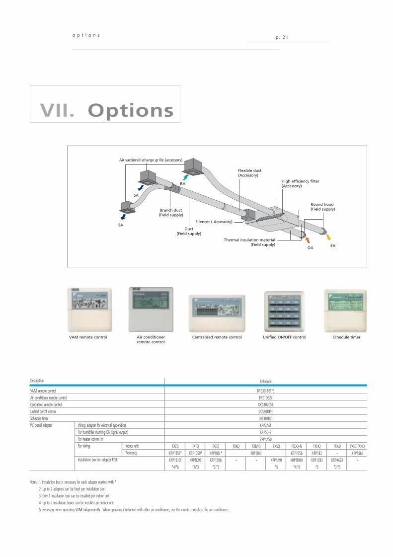
o p t i o n s p. 21
VII. Options
Air suction/discharge grille (accessory)
Branch duct(Field supply)
Round hood(Field supply)
High efficiency filter(Accessory)
Flexible duct(Accessory)
Duct(Field supply)
Silencer ( Accessory)
Thermal insulation material(Field supply)
SA
SA
RA
OA EA
VAM remote control Air conditionerremote control
Centralised remote control Unified ON/OFF control Schedule timer
Reference
BRC301B61*5
BRC1D527
DCS302C51
DCS301B51
DST301B51
KRP2A61
KRP50-2
BRP4A50
FXZQ FXFQ FXCQ FXKQ FXMQ FXSQ FXDQ-N FXHQ FXAQ FXLQ/FXNQ
KRP1B57* KRP1B59* KRP1B61* KRP1D61 KRP1B56 KRP1B3 - KRP1B61
KRP1B101 KRP1D98 KRP1B96 - - KRP4A91 KRP1B101 KRP1C93 KRP4A93 -
*4/*6 *2/*3 *2/*3 *5 *4/*6 *3 *2/*3
Description
VAM remote controlAir conditioner remote controlCentralised remote controlUnified on/off controlSchedule timerPC board adapter Wiring adapter for electrical appendices
For humidifier (running ON signal output)For heater control kitFor wiring indoor unit
ReferenceInstallation box for adapter PCB
Notes : 1. Installation box is necessary for each adapter marked with *2. Up to 2 adapters can be fixed per installation box3. Only 1 installation box can be installed per indoor unit4. Up to 2 installation boxes can be installed per indoor unit5. Necessary when operating VAM independently. When operating interlocked with other air conditioners, use the remote controls of the air conditioners
EPCE05-44A 30/09/05 8:37 Page 21
MOV91822_EPCe05-44A
Cyan Magenta Yellow Black
p. 22
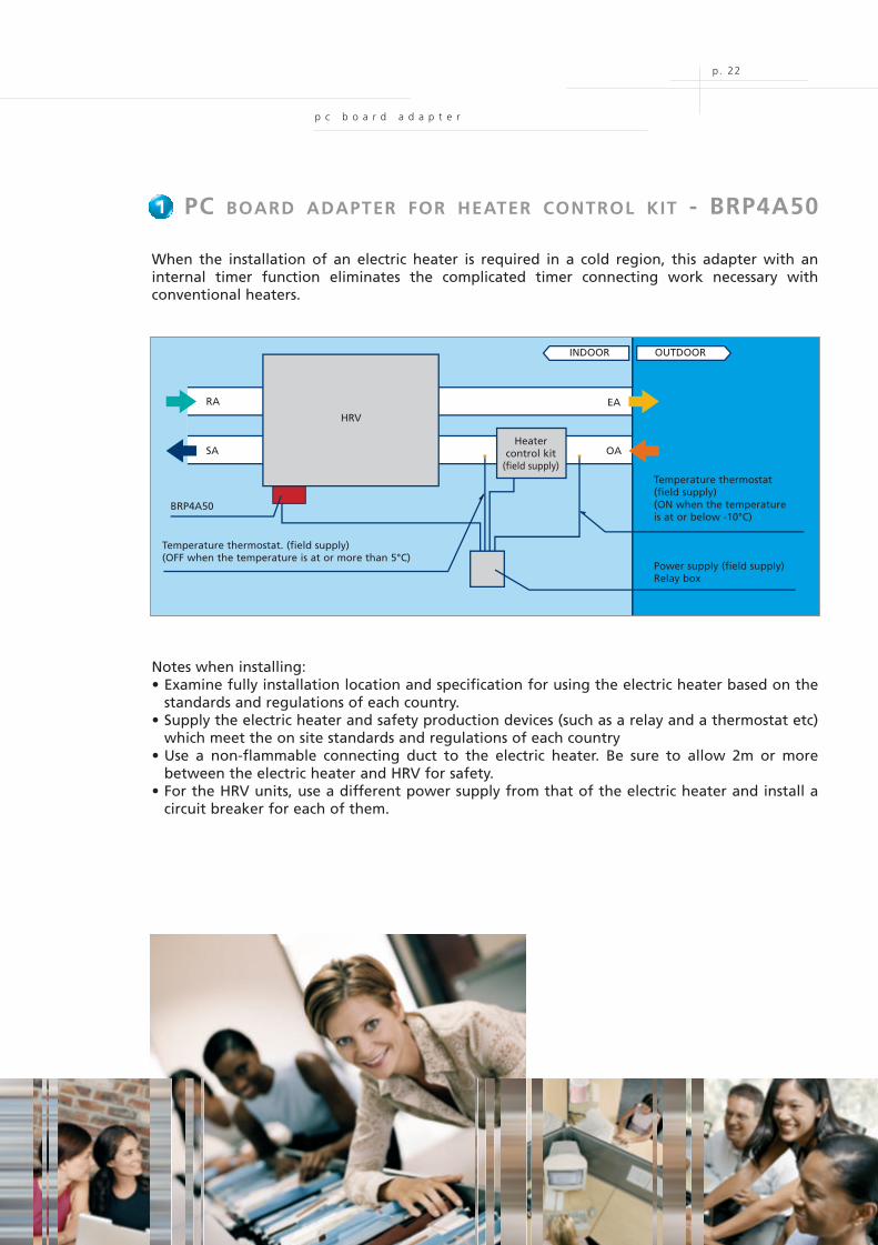
1. PC BOARD ADAPTER FOR HEATER CONTROL KIT - BRP4A50
When the installation of an electric heater is required in a cold region, this adapter with aninternal timer function eliminates the complicated timer connecting work necessary withconventional heaters.
Notes when installing:• Examine fully installation location and specification for using the electric heater based on the
standards and regulations of each country.• Supply the electric heater and safety production devices (such as a relay and a thermostat etc)
which meet the on site standards and regulations of each country• Use a non-flammable connecting duct to the electric heater. Be sure to allow 2m or more
between the electric heater and HRV for safety.• For the HRV units, use a different power supply from that of the electric heater and install a
circuit breaker for each of them.
1
RA EA
Heatercontrol kit
(field supply)
SA
Temperature thermostat. (field supply)(OFF when the temperature is at or more than 5°C)
Power supply (field supply)Relay box
Temperature thermostat(field supply)(ON when the temperatureis at or below -10°C)
INDOOR OUTDOOR
BRP4A50
HRV
OA
p c b o a r d a d a p t e r
EPCE05-44A 30/09/05 8:37 Page 22
MOV91822_EPCe05-44A
Cyan Magenta Yellow Black
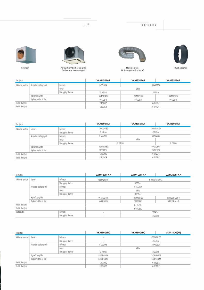
Description
Additional functions Air suction discharge grille ReferenceColourNom. piping diameter
High efficiency filterReplacement for air filter
Flexible duct (1m)Flexible duct (2m)
o p t i o n sp. 23
VAM150FA7 VAM250FA7 VAM350FA7
K-DGL100A K-DGL250B
White
Ø 100mm Ø 150mm
YAFM323F15 YAFM323F25 YAFM323F35
YAFF323F15 YAFF323F25 YAFF323F35
K-FDS101C K-FDS151C
K-FDS102B K-FDS152C
Description
Additional functions Silencer ReferenceNom. piping diameter
Air suction discharge grille ReferenceColourNom. piping diameter
High efficiency filterReplacement for air filter
Flexible duct (1m)Flexible duct (2m)
VAM500FA7 VAM650FA7 VAM800FA7
KDDM24A50 KDDM24A100
Ø 200mm Ø 250mm
K-DGL200A K-DGL250A
White
Ø 200mm Ø 250mm
YAFM323F50 YAFM323F65
YAFF323F50 YAFF323F65
K-FDS201C K-FDS251C
K-FDS202B K-FDS252C
Description
Additional functions Silencer ReferenceNom. piping diameter
Air suction discharge grille ReferenceColourNom. piping diameter
High efficiency filterReplacement for air filter
Flexible duct (1m)Flexible duct (2m)
Duct adapter Reference
Nom. piping diameter
VAM1000FA7 VAM1500FA7 VAM2000FA7
KDDM24A100 K-DDM24A100 x 2
Ø 250mm
K-DGL250A
White
Ø 250mm
YAFM323F100 YAFM323F65 YAFM323F100 x 2
YAFF323F100 YAFF323F65 YAFF323F100 x 2
K-FDS251C
K-FDS252C
- YDFA25A1
- Ø 250mm
Description
Additional functions Silencer ReferenceNom. piping diameter
Air suction discharge grille ReferenceColourNom. piping diameter
High efficiency filterReplacement for air filter
Flexible duct (1m)Flexible duct (2m)
VKM50G(M) VKM80G(M) VKM100G(M)
- K-DDM24B100
- Ø 250mm
K-DGL200B K-DGL250B
White
Ø 200mm Ø 250mm
KAF241G80M KAF241G100M
KAF242G80M KAF242G100M
K-FDS201C K-FDS251C
K-FDS202C K-FDS252C
Silencer Air suction/discharge grille(Noise suppression type)
Flexible duct(Noise suppression type)
Duct adapter
EPCE05-44A 30/09/05 8:37 Page 23
MOV91822_EPCe05-44A
Cyan Magenta Yellow Black
EPC
E05-
44A
/ 4
40 /
09/
05
La M
ovid
aPr
inte
d on
non
-chl
orin
ated
pap
er /
Prin
ted
in B
elgi
um
Daikin products are distributed by:
Zandvoordestraat 300
B-8400 Oostende, Belgium
www.daikineurope.com
“The present catalogue is drawn up by way of information onlyand does not constitute an offer binding upon Daikin EuropeN.V.. Daikin Europe N.V. has compiled the content of thiscatalogue to the best of its knowledge. No express or impliedwarranty is given for the completeness, accuracy, reliability orfitness for particular purpose of its content and the productsand services presented therein. Specifications are subject tochange without prior notice. Daikin Europe N.V. explicitly rejectsany liability for any direct or indirect damage, in the broadestsense, arising from or related to the use and/or interpretation ofthis catalogue. All content is copyrighted by Daikin Europe N.V..”
Daikin Europe N.V. is approved by LRQA for itsQuality Management System in accordance withthe ISO9001 standard.ISO9001 pertains to quality assurance regardingdesign, development, manufacturing as well as toservices related to the product.
ISO14001 assures an effective environmentalmanagement system in order to help protect humanhealth and the environment from the potentialimpact of our activities, products and services andto assist in maintaining and improving the qualityof the environment.
Daikin units comply with the European regulationsthat guarantee the safety of the product.
VRV products are not within the scope ofthe Eurovent certification programme
EPCE05-44A 30/09/05 8:37 Page 24
MOV91822_EPCe05-44A
Cyan Magenta Yellow Black