hp notebook pc (amd) hp 255 g4 notebook pc - qvc notebook pc (amd) hp 255 g4 notebook pc ... product...
TRANSCRIPT

HP Notebook PC (AMD)HP 255 G4 Notebook PC
Maintenance and Service Guide

© Copyright 2015 Hewlett-PackardDevelopment Company, L.P.
Intel is a trademark of Intel Corporation in theU.S. and other countries. AMD is a trademark ofAdvanced Micro Devices, Inc. Microsoft andWindows are U.S. registered trademarks ofMicrosoft Corporation. SD Logo is a trademarkof its proprietor.
The information contained herein is subject tochange without notice. The only warranties forHP products and services are set forth in theexpress warranty statements accompanyingsuch products and services. Nothing hereinshould be construed as constituting anadditional warranty. HP shall not be liable fortechnical or editorial errors or omissionscontained herein.
First Edition: April 2015
Document Part Number: 808736-001
Product notice
This guide describes features that are commonto most models. Some features may not beavailable on your computer.
Not all features are available on all editions ofWindows 8.1. This computer may requireupgraded and/or separately purchasedhardware, drivers, and/or software to take fulladvantage of Windows 8.1 functionality. Seehttp://www.microsoft.com for details.

Safety warning notice
WARNING! To reduce the possibility of heat-related injuries or of overheating the device, do not place thedevice directly on your lap or obstruct the device air vents. Use the device only on a hard, flat surface. Do notallow another hard surface, such as an adjoining optional printer, or a soft surface, such as pillows or rugs orclothing, to block airflow. Also, do not allow the AC adapter to contact the skin or a soft surface, such aspillows or rugs or clothing, during operation. The device and the AC adapter comply with the user-accessiblesurface temperature limits defined by the International Standard for Safety of Information TechnologyEquipment (IEC 60950-1).
iii

iv Safety warning notice

Table of contents
1 Product description ....................................................................................................................................... 1
2 External component identification ................................................................................................................. 5
Display ................................................................................................................................................................... 5
Right side ............................................................................................................................................................... 6
Left side ................................................................................................................................................................. 7
Top ......................................................................................................................................................................... 8
TouchPad ............................................................................................................................................. 8
Lights ................................................................................................................................................... 9
Buttons .............................................................................................................................................. 10
Keys ................................................................................................................................................... 11
Bottom ................................................................................................................................................................. 12
Labels ................................................................................................................................................................... 13
3 Illustrated parts catalog .............................................................................................................................. 15
Computer major components ............................................................................................................................. 15
Mass storage devices .......................................................................................................................................... 18
Miscellaneous parts ............................................................................................................................................. 19
Display assembly subcomponents ..................................................................................................................... 20
4 Removal and replacement procedures preliminary requirements .................................................................... 23
Tools required ...................................................................................................................................................... 23
Service considerations ........................................................................................................................................ 23
Plastic parts ....................................................................................................................................... 23
Cables and connectors ...................................................................................................................... 23
Drive handling ................................................................................................................................... 24
Grounding guidelines ........................................................................................................................................... 24
Electrostatic discharge damage ....................................................................................................... 24
Packaging and transporting guidelines ......................................................................... 25
Workstation guidelines ................................................................................ 25
5 Removal and replacement procedures for Customer Self-Repair parts ............................................................. 27
Component replacement procedures ................................................................................................................. 27
Battery ............................................................................................................................................... 28
Optical drive ...................................................................................................................................... 29
v

6 Removal and replacement procedures for Authorized Service Provider parts ................................................... 31
Component replacement procedures ................................................................................................................. 31
Display subcomponents (bezel, webcam, panel) ............................................................................. 31
Bottom cover ..................................................................................................................................... 35
Optical drive board ............................................................................................................................ 37
Hard drive .......................................................................................................................................... 38
WLAN module .................................................................................................................................... 40
Memory module ................................................................................................................................ 42
RTC battery ........................................................................................................................................ 43
USB board .......................................................................................................................................... 44
Speakers ............................................................................................................................................ 45
Heat sink assembly ........................................................................................................................... 46
Fan ..................................................................................................................................................... 49
TouchPad button board .................................................................................................................... 50
System board .................................................................................................................................... 51
Display assembly .............................................................................................................................. 54
Power connector cable ...................................................................................................................... 60
Power button board .......................................................................................................................... 61
7 Using Setup Utility (BIOS) in Windows 8.1 ...................................................................................................... 63
Starting Setup Utility (BIOS) ................................................................................................................................ 63
Updating the BIOS ................................................................................................................................................ 63
Determining the BIOS version ........................................................................................................... 63
Downloading a BIOS update .............................................................................................................. 63
8 Using Setup Utility (BIOS) in Windows 7 ......................................................................................................... 65
Starting Setup Utility (BIOS) ................................................................................................................................ 65
Updating the BIOS ................................................................................................................................................ 65
Determining the BIOS version ........................................................................................................... 65
Downloading a BIOS update .............................................................................................................. 65
9 Backing up, restoring, and recovering in Windows 8.1 .................................................................................... 67
Creating recovery media and backups ................................................................................................................ 67
Creating HP Recovery media (select models only) ........................................................................... 67
Using Windows tools ........................................................................................................................................... 68
Restore and recovery .......................................................................................................................................... 68
Recovering using HP Recovery Manager .......................................................................................... 69
What you need to know before you get started ............................................................ 69
Using the HP Recovery partition (select models only) .................................................. 70
Using HP Recovery media to recover ............................................................................. 70
vi

Changing the computer boot order ................................................................................ 71
Removing the HP Recovery partition (select models only) ........................................... 71
10 Backing up, restoring, and recovering in Windows 7 ..................................................................................... 73
Creating backups ................................................................................................................................................. 73
Creating recovery media to recover the original system ................................................................. 73
What you need to know .................................................................................................. 73
Creating the recovery media ........................................................................ 74
Creating system restore points ........................................................................................................ 74
What you need to know .................................................................................................. 74
Creating a system restore point ..................................................................................... 74
Backing up system and personal information .................................................................................. 74
Tips for a successful backup ........................................................................................... 75
What you need to know .................................................................................................. 75
Creating a backup using Windows Backup and Restore ................................................ 75
Restore and recovery .......................................................................................................................................... 76
Restoring to a previous system restore point .................................................................................. 76
Restoring specific files ...................................................................................................................... 76
Restoring specific files using Windows Backup and Restore ......................................... 76
Recovering the original system using HP Recovery Manager .......................................................... 76
What you need to know .................................................................................................. 76
Recovering using HP Recovery partition (select models only) ...................................... 77
Recovering using the recovery media ............................................................................ 77
Changing the computer boot order .............................................................. 77
11 Using HP PC Hardware Diagnostics (UEFI) ..................................................................................................... 79
Downloading HP PC Hardware Diagnostics (UEFI) to a USB device .................................................................... 79
12 Specifications ........................................................................................................................................... 81
Computer specifications ...................................................................................................................................... 81
39.6-cm (15.6-in) display specifications ............................................................................................................ 82
Hard drive specifications, hybrid drives .............................................................................................................. 82
Hard drive specifications ..................................................................................................................................... 83
DVD±RW SuperMulti DL Drive specifications ...................................................................................................... 84
13 Statement of Volatility .............................................................................................................................. 85
Non-volatile memory usage ................................................................................................................................ 87
Questions and answers ....................................................................................................................................... 89
vii

14 Power cord set requirements ...................................................................................................................... 91
Requirements for all countries ........................................................................................................................... 91
Requirements for specific countries and regions ............................................................................................... 92
15 Recycling .................................................................................................................................................. 95
Index ............................................................................................................................................................. 97
viii
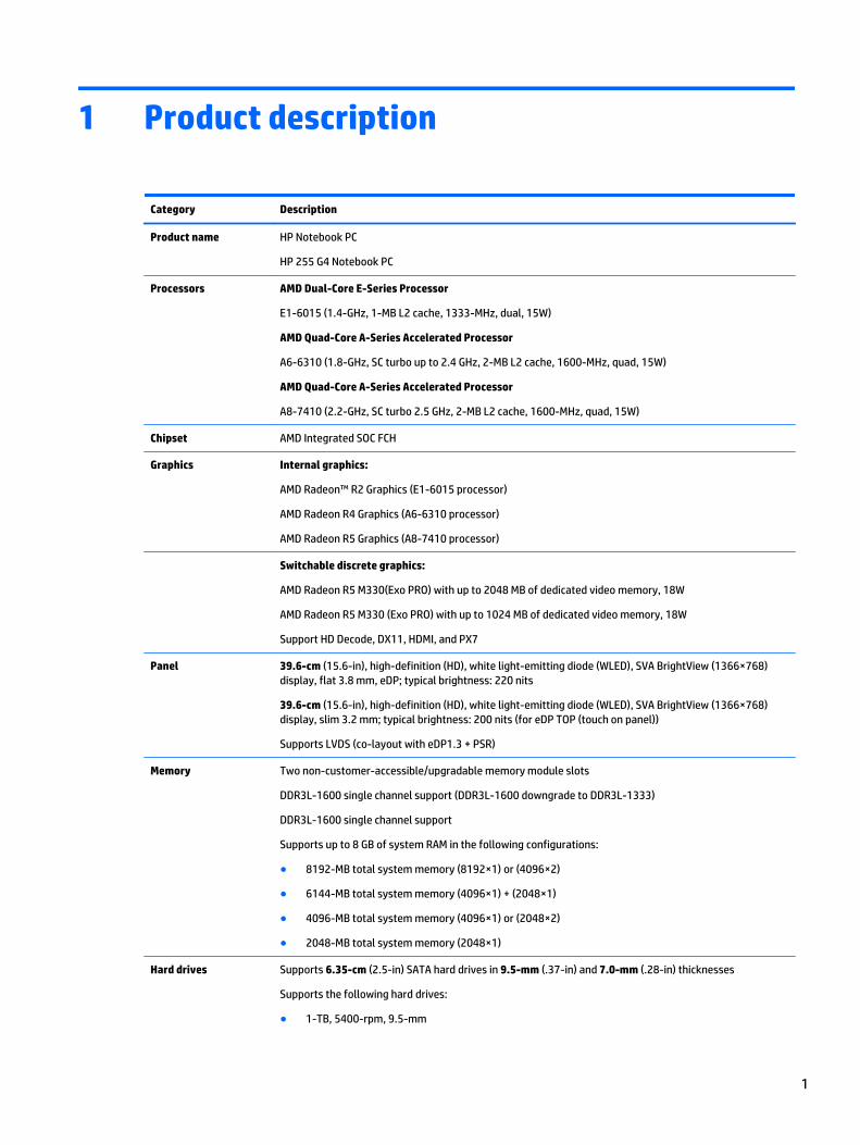
1 Product description
Category Description
Product name HP Notebook PC
HP 255 G4 Notebook PC
Processors AMD Dual-Core E-Series Processor
E1-6015 (1.4-GHz, 1-MB L2 cache, 1333-MHz, dual, 15W)
AMD Quad-Core A-Series Accelerated Processor
A6-6310 (1.8-GHz, SC turbo up to 2.4 GHz, 2-MB L2 cache, 1600-MHz, quad, 15W)
AMD Quad-Core A-Series Accelerated Processor
A8-7410 (2.2-GHz, SC turbo 2.5 GHz, 2-MB L2 cache, 1600-MHz, quad, 15W)
Chipset AMD Integrated SOC FCH
Graphics Internal graphics:
AMD Radeon™ R2 Graphics (E1-6015 processor)
AMD Radeon R4 Graphics (A6-6310 processor)
AMD Radeon R5 Graphics (A8-7410 processor)
Switchable discrete graphics:
AMD Radeon R5 M330(Exo PRO) with up to 2048 MB of dedicated video memory, 18W
AMD Radeon R5 M330 (Exo PRO) with up to 1024 MB of dedicated video memory, 18W
Support HD Decode, DX11, HDMI, and PX7
Panel 39.6-cm (15.6-in), high-definition (HD), white light-emitting diode (WLED), SVA BrightView (1366×768)display, flat 3.8 mm, eDP; typical brightness: 220 nits
39.6-cm (15.6-in), high-definition (HD), white light-emitting diode (WLED), SVA BrightView (1366×768)display, slim 3.2 mm; typical brightness: 200 nits (for eDP TOP (touch on panel))
Supports LVDS (co-layout with eDP1.3 + PSR)
Memory Two non-customer-accessible/upgradable memory module slots
DDR3L-1600 single channel support (DDR3L-1600 downgrade to DDR3L-1333)
DDR3L-1600 single channel support
Supports up to 8 GB of system RAM in the following configurations:
● 8192-MB total system memory (8192×1) or (4096×2)
● 6144-MB total system memory (4096×1) + (2048×1)
● 4096-MB total system memory (4096×1) or (2048×2)
● 2048-MB total system memory (2048×1)
Hard drives Supports 6.35-cm (2.5-in) SATA hard drives in 9.5-mm (.37-in) and 7.0-mm (.28-in) thicknesses
Supports the following hard drives:
● 1-TB, 5400-rpm, 9.5-mm
1

Category Description
● 1-TB, 5400-rpm + 8 GB NAND hybrid, 9.5-mm
● 750-GB, 5400-rpm, 9.5-mm
● 500-GB, 5400-rpm, 9.5-mm or 7.0-mm
● 320-GB, 7200-rpm, 9.5-mm or 7.0-mm
Optical drive Fixed, serial ATA, 9.5-mm tray load
DVD+/-RW Double-Layer SuperMulti
Supports zero power optical drive
Supports M-disc
Supports configuration without optical drive
Webcam/microphone HP TrueVision HD: HD camera - Fixed (no tilt) + activity LED, USB 2.0, M-JPEG, 1280 x 720 by 30 frames persecond
HP Webcam– 640 x 480 by 24 frames per second
Single digital microphone
HP Noise Cancellation enabled
Audio Dual speakers
DTS Sound
Ethernet Integrated 10/100 network interface card (NIC)
Sensor TPM (Trusted Platform Module) 2.0
Wireless Networking Integrated wireless options with single antenna (M.2):
Compatible with Miracast-certified devices
Support for the following WLAN formats:
● Realtek RTL8188EE 802.11bgn 1x1 Wi-Fi Adapter
● Realtek RT8723BE 802.11bgn 1x1 Wi-Fi + BT4.0 Combo Adapter
● Broadcom BCM43142 802.11 bgn 1x1 Wi-Fi + BT4.0 HMC Combo Adapter
External media card HP Multi-Format Digital Media Reader
Support SD/SDHC/SDXC
Push-Pull Insertion/Removal
Internal Card One M.2 slot for WLAN
Ports HDMI version 1.4 supporting 1920 ×1080 @ 60Hz
Hot Plug/unplug and auto detect for correct output to wide-aspect vs. standard aspect video
RJ-45 (Ethernet, includes link and activity lights)
USB 3.0 (1 port; left side)
USB 2.0 (2 ports; 1 left side, 1 right side)
AC Smart Pin adapter plug
Headphone/line in jack
Microphone input jack
2 Chapter 1 Product description

Category Description
Keyboard/pointingdevices
Full-size "island style" keyboard with numeric keypad
TouchPad with multi-touch gestures, 2-finger scrolling, and pinch-zoom enabled
Taps enabled by default
Support Windows 8 Modern Trackpad Gestures
Power requirements AC adapters:
65-W Smart nPFC, 3 pin, RC 4.5mm connector - non slim for use in discrete models
45-W Smart nPFC, 3 pin, RC 4.5mm connector - non slim for use in UMA models
65-W EM Smart nPFC, 3 pin, RC 4.5mm connector, 90 degree plug design for use in India/China
1 meter power cord
Batteries:
4-cell, 41-Whr Li-ion battery
3-cell, 31-Whr Li-ion battery
Security TPM 2.0
Kensington Security Lock
Operating system Preinstalled:
● Windows 8.1
● Windows 8.1 CPPP - China only
● Windows 7 Professional
● FreeDOS 2.0
Serviceability End-user replaceable parts:
● AC adapter
● Battery
● Optical drive
3

4 Chapter 1 Product description

2 External component identification
Display
Component Description
(1) Internal display switch Turns off the display and initiates Sleep if the display is closed while the power is on.
NOTE: The internal display switch is not visible from the outside of the computer.
(2) WLAN antenna* Send and receive wireless signals to communicate with wireless local area networks(WLANs).
(3) Webcam light On: The webcam is in use.
(4) Webcam Records video and captures photographs. Some models allow you to video conference andchat online using streaming video.
To use the webcam:
▲ Windows 8.1: From the Start screen, type camera, and then select Camera from thelist of applications.
▲ Windows 7: To use the webcam, select Start > All Programs > Communication andChat > CyberLink YouCam.
(5) Internal microphone Record sound.
*The antennas are not visible from the outside of the computer. For optimal transmission, keep the areas immediately around theantennas free from obstructions. For wireless regulatory notices, see the section of the Regulatory, Safety, and Environmental Noticesthat applies to your country or region.
To access this document in Windows 8.1:
From the Start screen, type support, and then select the HP Support Assistant app.
‒ or –
From the Windows desktop, click the question mark icon in the notification area, at the far right of the taskbar.
To access this document in Windows 7: Select Start > HP Support Assistant > Next > My computer > User Guides.
Display 5
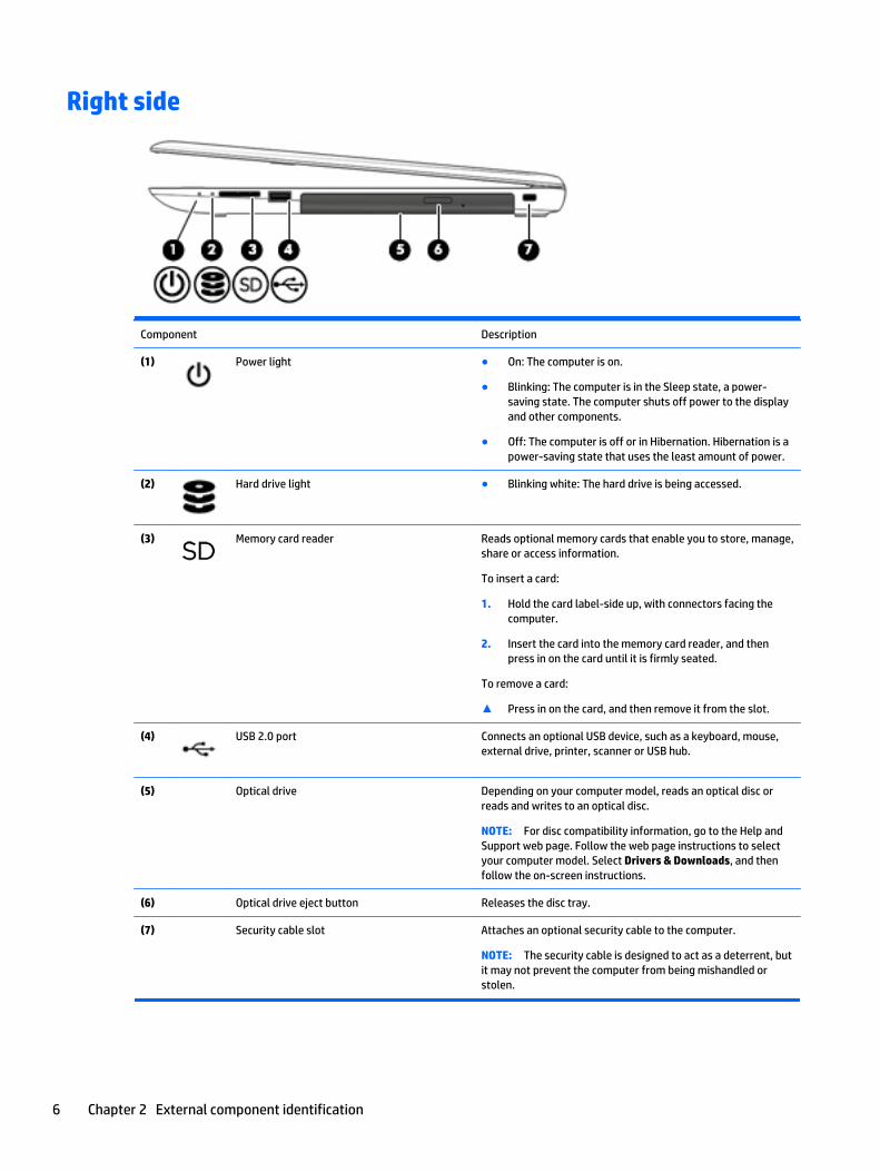
Right side
Component Description
(1) Power light ● On: The computer is on.
● Blinking: The computer is in the Sleep state, a power-saving state. The computer shuts off power to the displayand other components.
● Off: The computer is off or in Hibernation. Hibernation is apower-saving state that uses the least amount of power.
(2) Hard drive light ● Blinking white: The hard drive is being accessed.
(3) Memory card reader Reads optional memory cards that enable you to store, manage,share or access information.
To insert a card:
1. Hold the card label-side up, with connectors facing thecomputer.
2. Insert the card into the memory card reader, and thenpress in on the card until it is firmly seated.
To remove a card:
▲ Press in on the card, and then remove it from the slot.
(4) USB 2.0 port Connects an optional USB device, such as a keyboard, mouse,external drive, printer, scanner or USB hub.
(5)
Optical drive Depending on your computer model, reads an optical disc orreads and writes to an optical disc.
NOTE: For disc compatibility information, go to the Help andSupport web page. Follow the web page instructions to selectyour computer model. Select Drivers & Downloads, and thenfollow the on-screen instructions.
(6) Optical drive eject button Releases the disc tray.
(7) Security cable slot Attaches an optional security cable to the computer.
NOTE: The security cable is designed to act as a deterrent, butit may not prevent the computer from being mishandled orstolen.
6 Chapter 2 External component identification

Left side
Component Description
(1) Power connector Connects an AC adapter.
(2) AC adapter/battery light ● White: The AC adapter is connected and the battery is fullycharged.
● Blinking white: The AC adapter is disconnected and thebattery has reached a low battery level.
● Amber: The AC adapter is connected and the battery ischarging.
● Off: The battery is not charging.
(3) Vent Enable airflow to cool internal components.
NOTE: The computer fan starts up automatically to coolinternal components and prevent overheating. It is normal forthe internal fan to cycle on and off during routine operation.
(4) External monitor port (select models only) Connects an external VGA monitor or projector.
(5) RJ-45 (network) jack/status lights Connects a network cable.
● White: The network is connected.
● Amber: Activity is occurring on the network.
(6) HDMI port Connects an optional video or audio device, such as a high-definition television, any compatible digital or audiocomponent, or a high-speed High-Definition MultimediaInterface (HDMI) device.
(7) USB 3.0 port Connects an optional USB device, such as a keyboard, mouse,external drive, printer, scanner or USB hub.
(8) USB 2.0 port Connects an optional USB device, such as a keyboard, mouse,external drive, printer, scanner or USB hub.
(9) Audio-out (headphone)/Audio-in (microphone)jack
Connects optional powered stereo speakers, headphones,earbuds, a headset, or a television audio cable. Also connects anoptional headset microphone. This jack does not supportoptional microphone-only devices.
Left side 7

Component Description
WARNING! To reduce the risk of personal injury, adjust thevolume before putting on headphones, earbuds, or a headset.For additional safety information, refer to the Regulatory,Safety, and Environmental Notices.
To access this document:
▲ From the Start screen, type support, and then select theHP Support Assistant app.
‒ or –
From the Windows desktop, click the question mark icon inthe notification area, at the far right of the taskbar.
NOTE: When a device is connected to the jack, the computerspeakers are disabled.
NOTE: Be sure that the device cable has a 4-conductorconnector that supports both audio-out (headphone) and audio-in (microphone).
Top
TouchPad
Component Description
(1) TouchPad zone Reads your finger gestures to move the pointer or activateitems on the screen.
(2) Left TouchPad button Functions like the left button on an external mouse.
(3) Right TouchPad button Functions like the right button on an external mouse.
8 Chapter 2 External component identification

Lights
Component Description
(1) Caps lock light On: Caps lock is on, which switches the keys to all capital letters.
(2) Mute light ● Amber: Computer sound is off.
● Off: Computer sound is on.
Top 9

Buttons
Component Description
(1) Power button ● When the computer is off, press the button to turn on thecomputer.
● When the computer is on, press the button briefly toinitiate Sleep.
● When the computer is in the Sleep state, press the buttonbriefly to exit Sleep.
● When the computer is in Hibernation, press the buttonbriefly to exit Hibernation.
CAUTION: Pressing and holding down the power button willresult in the loss of unsaved information.
If the computer has stopped responding and Windows shutdownprocedures are ineffective, press and hold the power buttondown for at least 5 seconds to turn off the computer.
To learn more about your power settings in Windows 8.1, seeyour power options.
▲ From the Start screen, type power, select Power andsleep settings, and then select Power and sleep from thelist of applications.
‒ or –
From the Windows desktop, right-click the Start button,and then select Power Options.
To learn more about your power settings in Windows 7, selectStart > Control Panel > System and Security > Power Options.
10 Chapter 2 External component identification
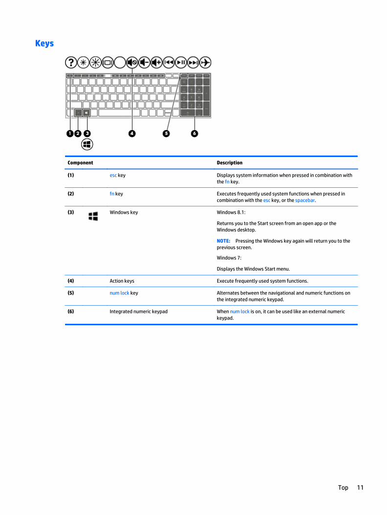
Keys
Component Description
(1) esc key Displays system information when pressed in combination withthe fn key.
(2) fn key Executes frequently used system functions when pressed incombination with the esc key, or the spacebar.
(3) Windows key Windows 8.1:
Returns you to the Start screen from an open app or theWindows desktop.
NOTE: Pressing the Windows key again will return you to theprevious screen.
Windows 7:
Displays the Windows Start menu.
(4) Action keys Execute frequently used system functions.
(5) num lock key Alternates between the navigational and numeric functions onthe integrated numeric keypad.
(6) Integrated numeric keypad When num lock is on, it can be used like an external numerickeypad.
Top 11

Bottom
Component Description
(1) Battery lock Locks the battery in the battery bay.
(2) Battery bay Holds the battery.
(3) Battery release latch Releases the battery.
(4) Speakers (2) Produce sound.
12 Chapter 2 External component identification
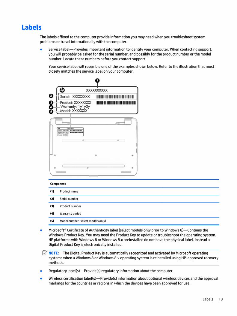
LabelsThe labels affixed to the computer provide information you may need when you troubleshoot systemproblems or travel internationally with the computer.
● Service label—Provides important information to identify your computer. When contacting support,you will probably be asked for the serial number, and possibly for the product number or the modelnumber. Locate these numbers before you contact support.
Your service label will resemble one of the examples shown below. Refer to the illustration that mostclosely matches the service label on your computer.
Component
(1) Product name
(2) Serial number
(3) Product number
(4) Warranty period
(5) Model number (select models only)
● Microsoft® Certificate of Authenticity label (select models only prior to Windows 8)—Contains theWindows Product Key. You may need the Product Key to update or troubleshoot the operating system.HP platforms with Windows 8 or Windows 8.x preinstalled do not have the physical label. Instead aDigital Product Key is electronically installed.
NOTE: The Digital Product Key is automatically recognized and activated by Microsoft operatingsystems when a Windows 8 or Windows 8.x operating system is reinstalled using HP-approved recoverymethods.
● Regulatory label(s)—Provide(s) regulatory information about the computer.
● Wireless certification label(s)—Provide(s) information about optional wireless devices and the approvalmarkings for the countries or regions in which the devices have been approved for use.
Labels 13

14 Chapter 2 External component identification

3 Illustrated parts catalog
Computer major componentsNOTE: HP continually improves and changes product parts. For complete and current information onsupported parts for your computer, go to http://partsurfer.hp.com, select your country or region, and thenfollow the on-screen instructions.
Computer major components 15
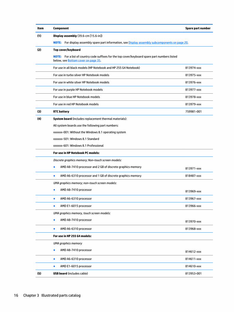
Item Component Spare part number
(1) Display assembly (39.6-cm [15.6-in])
NOTE: For display assembly spare part information, see Display assembly subcomponents on page 20.
(2) Top cover/keyboard
NOTE: For a list of country code suffixes for the top cover/keyboard spare part numbers listedbelow, see Bottom cover on page 35.
For use in all black models (HP Notebook and HP 255 G4 Notebook) 813974-xxx
For use in turbo silver HP Notebook models 813975-xxx
For use in white silver HP Notebook models 813976-xxx
For use in purple HP Notebook models 813977-xxx
For use in blue HP Notebook models 813978-xxx
For use in red HP Notebook models 813979-xxx
(3) RTC battery 759981-001
(4) System board (includes replacement thermal materials):
All system boards use the following part numbers:
xxxxxx-001: Without the Windows 8.1 operating system
xxxxxx-501: Windows 8.1 Standard
xxxxxx-601: Windows 8.1 Professional
For use in HP Notebook PC models:
Discrete graphics memory; Non-touch screen models:
● AMD A8-7410 processor and 2 GB of discrete graphics memory 813971-xxx
● AMD A6-6310 processor and 1 GB of discrete graphics memory 818487-xxx
UMA graphics memory; non-touch screen models:
● AMD A8-7410 processor 813969-xxx
● AMD A6-6310 processor 813967-xxx
● AMD E1-6015 processor 813966-xxx
UMA graphics memory, touch screen models:
● AMD A8-7410 processor 813970-xxx
● AMD A6-6310 processor 813968-xxx
For use in HP 255 G4 models:
UMA graphics memory
● AMD A8-7410 processor 814612-xxx
● AMD A6-6310 processor 814611-xxx
● AMD E1-6015 processor 814610-xxx
(5) USB board (includes cable) 813953-001
16 Chapter 3 Illustrated parts catalog
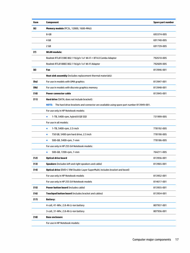
Item Component Spare part number
(6) Memory module (PC3L, 12800, 1600-MHz):
8-GB 693374-005
4 GB 691740-005
2 GB 691739-005
(7) WLAN module:
Realtek RTL8723BE 802.11b/g/n 1x1 Wi-Fi + BT4.0 Combo Adapter 792610-005
Realtek RTL8188EE 802.11b/g/n 1x1 Wi-Fi Adapter 792609-005
(8) Fan 813946-001
Heat sink assembly (includes replacement thermal materials):
(9a) For use in models with UMA graphics 813947-001
(9b) For use in models with discrete graphics memory 813948-001
(10) Power connector cable 813945-001
(11) Hard drive (SATA; does not include bracket):
NOTE: The hard drive brackets and connector are available using spare part number 813949-001.
For use only in HP Notebook models:
● 1-TB, 5400-rpm, hybrid 8 GB SSD 731999-005
For use in all models:
● 1-TB, 5400-rpm, 2.5-inch 778192-005
● 750 GB, 5400 rpm hard drive, 2.5 inch 778190-005
● 500-GB, 5400-rpm, 7-mm 778186-005
For use only in HP 255 G4 Notebook models:
● 500-GB, 7200-rpm, 7-mm 764211-005
(12) Optical drive board 813956-001
(13) Speakers (includes left and right speakers and cable) 813965-001
(14) Optical drive (DVD+/-RW Double-Layer SuperMulti; includes bracket and bezel)
For use only in HP Notebook models 813952-001
For use only in HP 255 G4 Notebook models 814617-001
(15) Power button board (includes cable) 813955-001
(16) Touchpad button board (includes bracket and cables) 813954-001
(17) Battery:
4-cell, 41-Whr, 2.8-Ah Li-ion battery 807957-001
3-cell, 31-Whr, 2.8-Ah Li-ion battery 807956-001
(18) Base enclosure
For use in HP Notebook models:
Computer major components 17
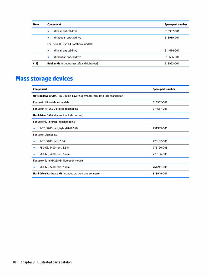
Item Component Spare part number
● With an optical drive 813937-001
● Without an optical drive 813939-001
For use in HP 255 G4 Notebook models:
● With an optical drive 814614-001
● Without an optical drive 816606-001
(19) Rubber Kit (includes rear left and right feet) 813963-001
Mass storage devices
Component Spare part number
Optical drive (DVD+/-RW Double-Layer SuperMulti; includes bracket and bezel)
For use in HP Notebook models 813952-001
For use in HP 255 G4 Notebook models 814617-001
Hard drive, SATA; does not include bracket):
For use only in HP Notebook models:
● 1-TB, 5400-rpm, hybrid 8 GB SSD 731999-005
For use in all models:
● 1-TB, 5400-rpm, 2.5-in 778192-005
● 750-GB, 5400-rpm, 2.5-in 778190-005
● 500-GB, 5400-rpm, 7-mm 778186-005
For use only in HP 255 G4 Notebook models:
● 500-GB, 7200-rpm, 7-mm 764211-005
Hard Drive Hardware Kit (includes brackets and connector) 813949-001
18 Chapter 3 Illustrated parts catalog

Miscellaneous parts
Component Spare part number
HP Smart AC adapter:
65-W non-PFC EM (for use in the People’s Republic of China and India only) 714657-001
65-W, non-PFC, 4.5 mm 710412-001
45-W non-PFC, non-slim (for use in all countries and regions except for the People’s Republic of Chinaand India)
741727-001
Power cord (3-pin, black, 1.0 m):
For use in Argentina 755530-D01
For use in Australia 755530-011
For use in Denmark 755530-081
For use in Europe, the Middle East, and Africa 755530-021
For use in India 755530-D61
For use in Italy 755530-061
For use in Japan 755530-291
For use in North America 755530-001
For use in the People's Republic of China 755530-AA1
For use in South Africa 755530-AR1
For use in South Korea 755530-AD1
For use in Switzerland 755530-111
For use in Taiwan 755530-AB1
For use in Thailand 755530-201
For use in the United Kingdom and Singapore 755530-031
Rubber Kit (includes front and rear feet) 813963-001
Screw Kit 813964-001
HP HDMI to VGA Adapter 701943-001
Miscellaneous parts 19

Display assembly subcomponents
Item Component Spare part number
(1) Display bezel (includes Mylar screw covers)
For use in HP Notebook models 813941-001
For use in HP 255 G4 Notebook models 814615-001
(2) Raw display panel (39.6-cm [15.6-in], HD, WLED, BrightView)
For use in models without a touch screen 813959-001
For use in models with a touch screen 813961-001
(3) Hinges (left and right) 813950-001
(4) Webcam/microphone module
For use in HP Notebook models 813972-001
For use in HP 255 G4 Notebook models 814613-001
(5) Antenna (includes wireless antenna cable and transceiver) 813923-001
(6) Display cable (includes display panel cable and webcam/microphone cable)
Non-touch screen 813943-001
Touch screen 813944-001
(7) Display enclosure:
For use in HP Notebook models without a touch screen:
● Black models 813925-001
20 Chapter 3 Illustrated parts catalog
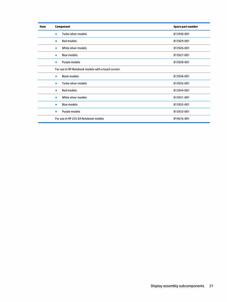
Item Component Spare part number
● Turbo silver models 813930-001
● Red models 813929-001
● White silver models 813926-001
● Blue models 813927-001
● Purple models 813928-001
For use in HP Notebook models with a touch screen:
● Black models 813936-001
● Turbo silver models 813935-001
● Red models 813934-001
● White silver models 813931-001
● Blue models 813932-001
● Purple models 813933-001
For use in HP 255 G4 Notebook models 814616-001
Display assembly subcomponents 21

22 Chapter 3 Illustrated parts catalog

4 Removal and replacement procedurespreliminary requirements
Tools requiredYou will need the following tools to complete the removal and replacement procedures:
● Flat-bladed screwdriver
● Magnetic screwdriver
● Phillips P0 and P1 screwdrivers
Service considerationsThe following sections include some of the considerations that you must keep in mind during disassemblyand assembly procedures.
NOTE: As you remove each subassembly from the computer, place the subassembly (and all accompanyingscrews) away from the work area to prevent damage.
Plastic parts
CAUTION: Using excessive force during disassembly and reassembly can damage plastic parts. Use carewhen handling the plastic parts. Apply pressure only at the points designated in themaintenance instructions.
Cables and connectors
CAUTION: When servicing the computer, be sure that cables are placed in their proper locations during thereassembly process. Improper cable placement can damage the computer.
Cables must be handled with extreme care to avoid damage. Apply only the tension required to unseat orseat the cables during removal and insertion. Handle cables by the connector whenever possible. In all cases,avoid bending, twisting, or tearing cables. Be sure that cables are routed in such a way that they cannot becaught or snagged by parts being removed or replaced. Handle flex cables with extreme care; these cablestear easily.
Tools required 23

Drive handling
CAUTION: Drives are fragile components that must be handled with care. To prevent damage to thecomputer, damage to a drive, or loss of information, observe these precautions:
Before removing or inserting a hard drive, shut down the computer. If you are unsure whether the computeris off or in Hibernation, turn the computer on, and then shut it down through the operating system.
Before handling a drive, be sure that you are discharged of static electricity. While handling a drive, avoidtouching the connector.
Before removing a diskette drive or optical drive, be sure that a diskette or disc is not in the drive and be surethat the optical drive tray is closed.
Handle drives on surfaces covered with at least one inch of shock-proof foam.
Avoid dropping drives from any height onto any surface.
After removing a hard drive, an optical drive, or a diskette drive, place it in a static-proof bag.
Avoid exposing an internal hard drive to products that have magnetic fields, such as monitors or speakers.
Avoid exposing a drive to temperature extremes or liquids.
If a drive must be mailed, place the drive in a bubble pack mailer or other suitable form of protectivepackaging and label the package “FRAGILE.”
Grounding guidelines
Electrostatic discharge damage
Electronic components are sensitive to electrostatic discharge (ESD). Circuitry design and structuredetermine the degree of sensitivity. Networks built into many integrated circuits provide some protection,but in many cases, ESD contains enough power to alter device parameters or melt silicon junctions.
A discharge of static electricity from a finger or other conductor can destroy static-sensitive devices ormicrocircuitry. Even if the spark is neither felt nor heard, damage may have occurred.
An electronic device exposed to ESD may not be affected at all and can work perfectly throughout a normalcycle. Or the device may function normally for a while, then degrade in the internal layers, reducing its lifeexpectancy.
CAUTION: To prevent damage to the computer when you are removing or installing internal components,observe these precautions:
Keep components in their electrostatic-safe containers until you are ready to install them.
Before touching an electronic component, discharge static electricity by using the guidelines described in thissection.
Avoid touching pins, leads, and circuitry. Handle electronic components as little as possible.
If you remove a component, place it in an electrostatic-safe container.
The following table shows how humidity affects the electrostatic voltage levels generated bydifferent activities.
CAUTION: A product can be degraded by as little as 700 V.
24 Chapter 4 Removal and replacement procedures preliminary requirements

Typical electrostatic voltage levels
Relative humidity
Event 10% 40% 55%
Walking across carpet 35,000 V 15,000 V 7,500 V
Walking across vinyl floor 12,000 V 5,000 V 3,000 V
Motions of bench worker 6,000 V 800 V 400 V
Removing DIPS from plastic tube 2,000 V 700 V 400 V
Removing DIPS from vinyl tray 11,500 V 4,000 V 2,000 V
Removing DIPS from Styrofoam 14,500 V 5,000 V 3,500 V
Removing bubble pack from PCB 26,500 V 20,000 V 7,000 V
Packing PCBs in foam-lined box 21,000 V 11,000 V 5,000 V
Packaging and transporting guidelines
Follow these grounding guidelines when packaging and transporting equipment:
● To avoid hand contact, transport products in static-safe tubes, bags, or boxes.
● Protect ESD-sensitive parts and assemblies with conductive or approved containers or packaging.
● Keep ESD-sensitive parts in their containers until the parts arrive at static-free workstations.
● Place items on a grounded surface before removing items from their containers.
● Always be properly grounded when touching a component or assembly.
● Store reusable ESD-sensitive parts from assemblies in protective packaging or non-conductive foam.
● Use transporters and conveyors made of antistatic belts and roller bushings. Be sure that mechanizedequipment used for moving materials is wired to ground and that proper materials are selected to avoidstatic charging. When grounding is not possible, use an ionizer to dissipate electric charges.
Workstation guidelines
Follow these grounding workstation guidelines:
● Cover the workstation with approved static-shielding material.
● Use a wrist strap connected to a properly grounded work surface and use properly grounded tools andequipment.
● Use conductive field service tools, such as cutters, screwdrivers, and vacuums.
● When fixtures must directly contact dissipative surfaces, use fixtures made only of static-safe materials.
● Keep the work area free of nonconductive materials, such as ordinary plastic assembly aidsand Styrofoam.
● Handle ESD-sensitive components, parts, and assemblies by the case or PCM laminate. Handle theseitems only at static-free workstations.
Grounding guidelines 25
● Avoid contact with pins, leads, or circuitry.
● Turn off power and input signals before inserting or removing connectors or test equipment.
Equipment guidelines
Grounding equipment must include either a wrist strap or a foot strap at a grounded workstation.
● When seated, wear a wrist strap connected to a grounded system. Wrist straps are flexible straps with aminimum of one megohm ±10% resistance in the ground cords. To provide proper ground, wear a strapsnugly against the skin at all times. On grounded mats with banana-plug connectors, use alligator clipsto connect a wrist strap.
● When standing, use foot straps and a grounded floor mat. Foot straps (heel, toe, or boot straps) can beused at standing workstations and are compatible with most types of shoes or boots. On conductivefloors or dissipative floor mats, use foot straps on both feet with a minimum of one megohm resistancebetween the operator and ground. To be effective, the conductive must be worn in contact with theskin.
The following grounding equipment is recommended to prevent electrostatic damage:
● Antistatic tape
● Antistatic smocks, aprons, and sleeve protectors
● Conductive bins and other assembly or soldering aids
● Nonconductive foam
● Conductive tabletop workstations with ground cords of one megohm resistance
● Static-dissipative tables or floor mats with hard ties to the ground
● Field service kits
● Static awareness labels
● Material-handling packages
● Nonconductive plastic bags, tubes, or boxes
● Metal tote boxes
● Electrostatic voltage levels and protective materials
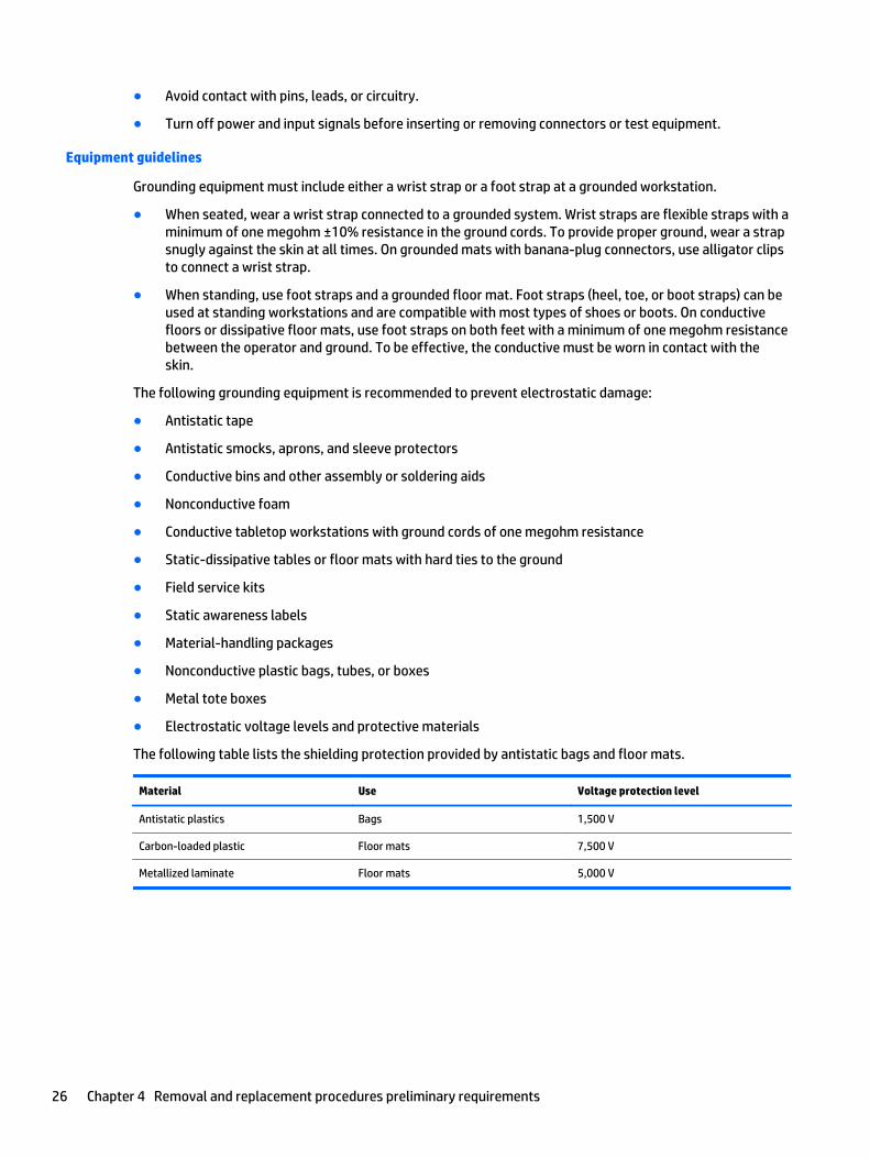
The following table lists the shielding protection provided by antistatic bags and floor mats.
Material Use Voltage protection level
Antistatic plastics Bags 1,500 V
Carbon-loaded plastic Floor mats 7,500 V
Metallized laminate Floor mats 5,000 V
26 Chapter 4 Removal and replacement procedures preliminary requirements

5 Removal and replacement procedures forCustomer Self-Repair parts
CAUTION: The Customer Self-Repair program is not available in all locations. Installing a part notsupported by the Customer Self-Repair program may void your warranty. Check your warranty to determineif Customer Self-Repair is supported in your location.
NOTE: HP continually improves and changes product parts. For complete and current information onsupported parts for your computer, go to http://partsurfer.hp.com, select your country or region, and thenfollow the on-screen instructions.
Component replacement proceduresNOTE: Please read and follow the procedures described here to access and replace Customer Self-Repairparts successfully.
NOTE: Details about your computer, including model, serial number, product key, and length of warranty,are on the service tag at the bottom of your computer. See Labels on page 13 for details.
This chapter provides removal and replacement procedures for Customer Self-Repair parts.
There are as many as 3 screws that must be removed, replaced, or loosened when servicing Customer Self-Repair parts. Make special note of each screw size and location during removal and replacement.
Component replacement procedures 27

Battery
Description Spare part number
4-cell, 41-Whr, 2.8-Ah Li-ion battery 807957-001
3-cell, 31-Whr, 2.8-Ah Li-ion battery 807956-001
Before disassembling the computer, follow these steps:
1. Shut down the computer. If you are unsure whether the computer is off or in Hibernation, turn thecomputer on, and then shut it down through the operating system.
2. Disconnect all external devices connected to the computer.
3. Disconnect the power from the computer by first unplugging the power cord from the AC outlet andthen unplugging the AC adapter from the computer.
To remove the battery:
1. Position the computer upside down on a flat surface.
2. Slide the battery lock latch (1), and then slide the battery release latch (2) to release the battery.
3. Remove the battery from the computer (3).
28 Chapter 5 Removal and replacement procedures for Customer Self-Repair parts
Optical drive
NOTE: Optical drive spare part kits include bracket and bezel.
Description Spare partnumber
DVD+/-RW Double-Layer SuperMulti Drive for use in HP Notebook models (includes bracket and bezel) 813952-001
DVD+/-RW Double-Layer SuperMulti Drive for use in HP 255 G4 Notebook models (includes bracket and bezel) 814617-001
Before removing the optical drive, follow these steps:
1. Shut down the computer. If you are unsure whether the computer is off or in Hibernation, turn thecomputer on, and then shut it down through the operating system.
2. Disconnect all external devices connected to the computer.
3. Disconnect the power from the computer by first unplugging the power cord from the AC outlet andthen unplugging the AC adapter from the computer.
4. Remove the battery (see Battery on page 28).
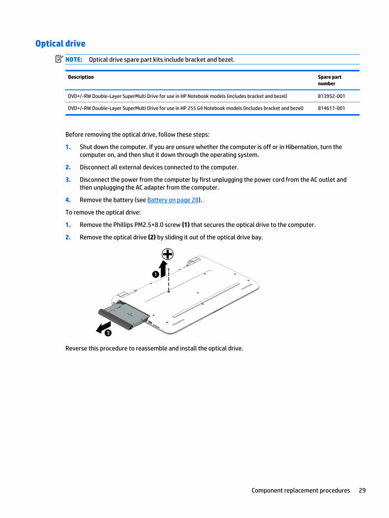
To remove the optical drive:
1. Remove the Phillips PM2.5×8.0 screw (1) that secures the optical drive to the computer.
2. Remove the optical drive (2) by sliding it out of the optical drive bay.
Reverse this procedure to reassemble and install the optical drive.
Component replacement procedures 29

30 Chapter 5 Removal and replacement procedures for Customer Self-Repair parts
6 Removal and replacement procedures forAuthorized Service Provider parts
CAUTION: Components described in this chapter should only be accessed by an authorized service provider.Accessing these parts can damage the computer or void the warranty.
NOTE: HP continually improves and changes product parts. For complete and current information onsupported parts for your computer, go to http://partsurfer.hp.com, select your country or region, and thenfollow the on-screen instructions.
Component replacement proceduresNOTE: Details about your computer, including model, serial number, product key, and length of warranty,are on the service tag at the bottom of your computer. See Labels on page 13 for details.
This chapter provides removal and replacement procedures for Authorized Service Provider only parts.
There are as many as 56 screws that must be removed, replaced, or loosened when servicing AuthorizedService Provider only parts. Make special note of each screw size and location during removal andreplacement.
Display subcomponents (bezel, webcam, panel)
This section describes removing display subcomponents that do not require that you remove the entiredisplay assembly from the computer. You can remove the display bezel, webcam/microphone module, anddisplay panel while the display assembly is still attached to the computer.
To remove the remaining display subcomponents, you must remove the entire display assembly from thecomputer. See Display assembly on page 54 for more information about removing the display assembly inits entirety.
Description Spare part number
Raw display panel
For use in models without a touch screen 813959-001
For use in models with a touch screen 813961-001
Display bezel (includes Mylar screw covers)
For use in Notebook models 813941-001
For use in HP 255 G4 Notebook models 814615-001
Webcam/microphone module
For use in HP Notebook models 813972-001
For use in HP 255 G4 Notebook models 814613-001
Component replacement procedures 31
Before removing display subcomponents while the display assembly is still attached to the computer, followthese steps:
1. Shut down the computer. If you are unsure whether the computer is off or in Hibernation, turn thecomputer on, and then shut it down through the operating system.
2. Disconnect all external devices connected to the computer.
3. Disconnect the power from the computer by first unplugging the power cord from the AC outlet andthen unplugging the AC adapter from the computer.
4. Remove the battery (see Battery on page 28).
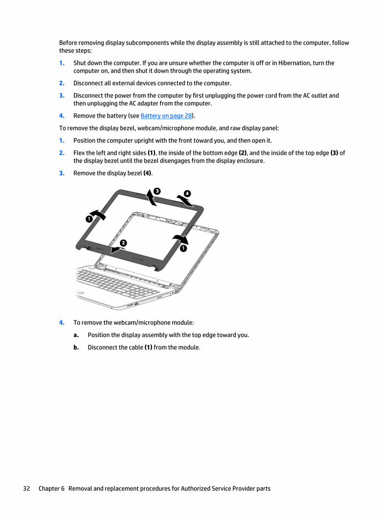
To remove the display bezel, webcam/microphone module, and raw display panel:
1. Position the computer upright with the front toward you, and then open it.
2. Flex the left and right sides (1), the inside of the bottom edge (2), and the inside of the top edge (3) ofthe display bezel until the bezel disengages from the display enclosure.
3. Remove the display bezel (4).
4. To remove the webcam/microphone module:
a. Position the display assembly with the top edge toward you.
b. Disconnect the cable (1) from the module.
32 Chapter 6 Removal and replacement procedures for Authorized Service Provider parts
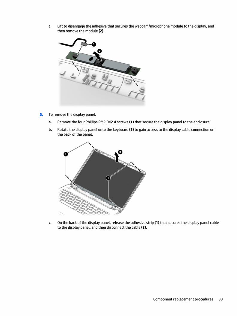
c. Lift to disengage the adhesive that secures the webcam/microphone module to the display, andthen remove the module (2).
5. To remove the display panel:
a. Remove the four Phillips PM2.0×2.4 screws (1) that secure the display panel to the enclosure.
b. Rotate the display panel onto the keyboard (2) to gain access to the display cable connection onthe back of the panel.
c. On the back of the display panel, release the adhesive strip (1) that secures the display panel cableto the display panel, and then disconnect the cable (2).
Component replacement procedures 33
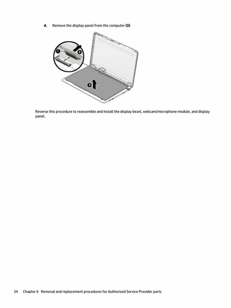
d. Remove the display panel from the computer (3).
Reverse this procedure to reassemble and install the display bezel, webcam/microphone module, and displaypanel.
34 Chapter 6 Removal and replacement procedures for Authorized Service Provider parts

Bottom cover
In this section, the first table provides the main spare part number for the top covers/keyboards. The secondtable provides the country code suffixes for the spare part number.
Description Spare part number
Top cover with keyboard for use in all black models (HP Notebook and HP 255 G4 Notebook) 813974-xxx
Top cover with keyboard for use in turbo silver HP Notebook models 813975-xxx
Top cover with keyboard for use in white silver HP Notebook models 813976-xxx
Top cover with keyboard for use in purple HP Notebook models 813977-xxx
Top cover with keyboard for use in blue HP Notebook models 813978-xxx
Top cover with keyboard for use in red HP Notebook models 813979-xxx
For use in countryor region
Spare partnumber
For use in countryor region
Spare partnumber
For use in countryor region
Spare partnumber
Belgium -A41 Italy -061 South Korea -AD1
Bulgaria -261 Japan -291 Spain -071
Canada -DB1 Latin America -161 Switzerland -BG1
Czech Republicand Slovakia
-FL1 The Netherlands -B31 Taiwan -AB1
Denmark, Finland, andNorway
-DH1 Portugal -131 Thailand -281
France -051 Romania -271 Turkey -141
Germany -041 Russia -251 United Kingdom -031
Greece -151 Saudi Arabia -171 United States -001
Hungary -211 Slovenia -BA1
Before removing the bottom cover, follow these steps:
1. Shut down the computer. If you are unsure whether the computer is off or in Hibernation, turn thecomputer on, and then shut it down through the operating system.
2. Disconnect all external devices connected to the computer.
3. Disconnect the power from the computer by first unplugging the power cord from the AC outlet andthen unplugging the AC adapter from the computer.
4. Remove the battery (see Battery on page 28).
5. Remove the optical drive (see Optical drive on page 29), if installed.
To remove the bottom cover:
1. Position the computer upside down with the front toward you.
2. Remove the two rubber bumpers from rear of the bottom of the computer (1)
Component replacement procedures 35
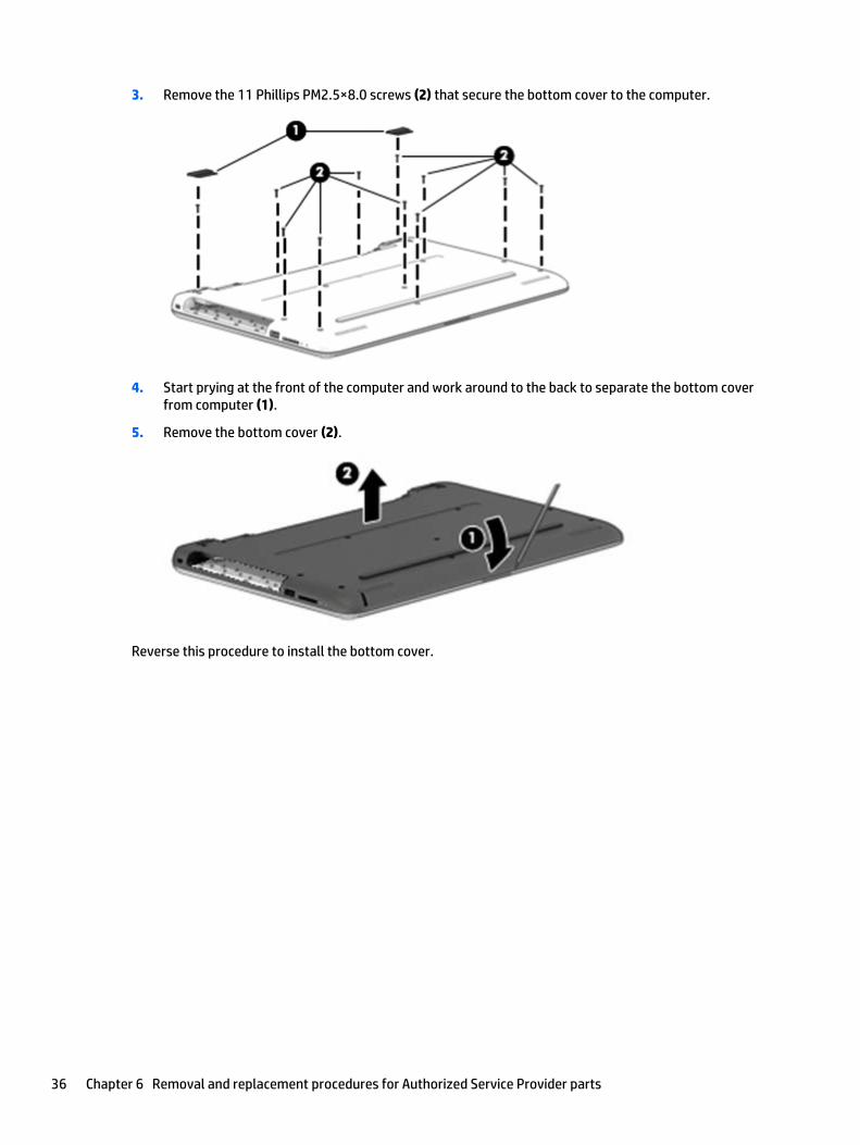
3. Remove the 11 Phillips PM2.5×8.0 screws (2) that secure the bottom cover to the computer.
4. Start prying at the front of the computer and work around to the back to separate the bottom coverfrom computer (1).
5. Remove the bottom cover (2).
Reverse this procedure to install the bottom cover.
36 Chapter 6 Removal and replacement procedures for Authorized Service Provider parts

Optical drive board
Description Spare part number
Optical drive board (includes cable) 813956-001
Before removing the optical drive board, follow these steps:
1. Shut down the computer. If you are unsure whether the computer is off or in Hibernation, turn thecomputer on, and then shut it down through the operating system.
2. Disconnect all external devices connected to the computer.
3. Disconnect the power from the computer by first unplugging the power cord from the AC outlet andthen unplugging the AC adapter from the computer.
4. Remove the battery (see Battery on page 28).
5. Remove the optical drive (see Optical drive on page 29), if installed.
6. Remove the bottom cover (see Bottom cover on page 35).
To remove the optical drive board:
1. Disconnect the cable from the system board (1).
2. Remove the Phillips PM2.0×2.4 screw (2) that secures the optical drive board to the computer.
3. Remove the board and cable from the computer (3).
Reverse this procedure to install the optical drive board and cable.
Component replacement procedures 37

Hard drive
NOTE: The hard drive spare part kit does not include the hard drive bracket.
Description Spare part number
For use only in HP Notebook models:
1-TB, 5400-rpm, hybrid 8 GB SSD 731999-005
For use in all models:
1-TB, 5400-rpm, 2.5-in 778192-005
750 GB, 5400 rpm, 2.5 in 778190-005
500-GB, 5400-rpm, 7-mm 778186-005
For use only in HP 255 G4 Notebook models:
500-GB, 7200-rpm, 7-mm 764211-005
Hard Drive Hardware Kit (includes brackets and connector) 813949-001
Before removing the hard drive, follow these steps:
1. Shut down the computer. If you are unsure whether the computer is off or in Hibernation, turn thecomputer on, and then shut it down through the operating system.
2. Disconnect all external devices connected to the computer.
3. Disconnect the power from the computer by first unplugging the power cord from the AC outlet andthen unplugging the AC adapter from the computer.
4. Remove the battery (see Battery on page 28).
5. Remove the optical drive (see Optical drive on page 29), if installed.
6. Remove the bottom cover (see Bottom cover on page 35).
To remove the hard drive:
1. Disconnect the hard drive cable from the system board (1).
2. Remove the three Phillips PM2.0×2.4 screws (2) that secure the hard drive assembly to the computer.
38 Chapter 6 Removal and replacement procedures for Authorized Service Provider parts

3. Lift the hard drive assembly from the computer (3).
4. To disassemble the hard drive, pull the connector away from the drive to remove it (1).
5. To remove the hard drive brackets, remove the two Phillips PM3.0×3.0 screws (2) that secure eachbracket to the hard drive.
6. Remove the hard drive brackets from the hard drive (3).
Reverse this procedure to reassemble and install the hard drive.
Component replacement procedures 39
WLAN module
Description Spare part number
Realtek RTL8723BE 802.11b/g/n 1x1 Wi-Fi + BT4.0 Combo Adapter 792610-005
Realtek RTL8188EE 802.11b/g/n 1x1 Wi-Fi Adapter 792609-005
CAUTION: To prevent an unresponsive system, replace the wireless module only with a wireless moduleauthorized for use in the computer by the governmental agency that regulates wireless devices in yourcountry or region. If you replace the module and then receive a warning message, remove the module torestore device functionality, and then contact support.
Before removing the WLAN module, follow these steps:
1. Shut down the computer. If you are unsure whether the computer is off or in Hibernation, turn thecomputer on, and then shut it down through the operating system.
2. Disconnect all external devices connected to the computer.
3. Disconnect the power from the computer by first unplugging the power cord from the AC outlet andthen unplugging the AC adapter from the computer.
4. Remove the battery (see Battery on page 28).
5. Remove the optical drive (see Optical drive on page 29), if installed.
6. Remove the bottom cover (see Bottom cover on page 35).
To remove the WLAN module:
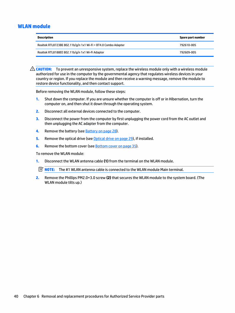
1. Disconnect the WLAN antenna cable (1) from the terminal on the WLAN module.
NOTE: The #1 WLAN antenna cable is connected to the WLAN module Main terminal.
2. Remove the Phillips PM2.0×3.0 screw (2) that secures the WLAN module to the system board. (TheWLAN module tilts up.)
40 Chapter 6 Removal and replacement procedures for Authorized Service Provider parts
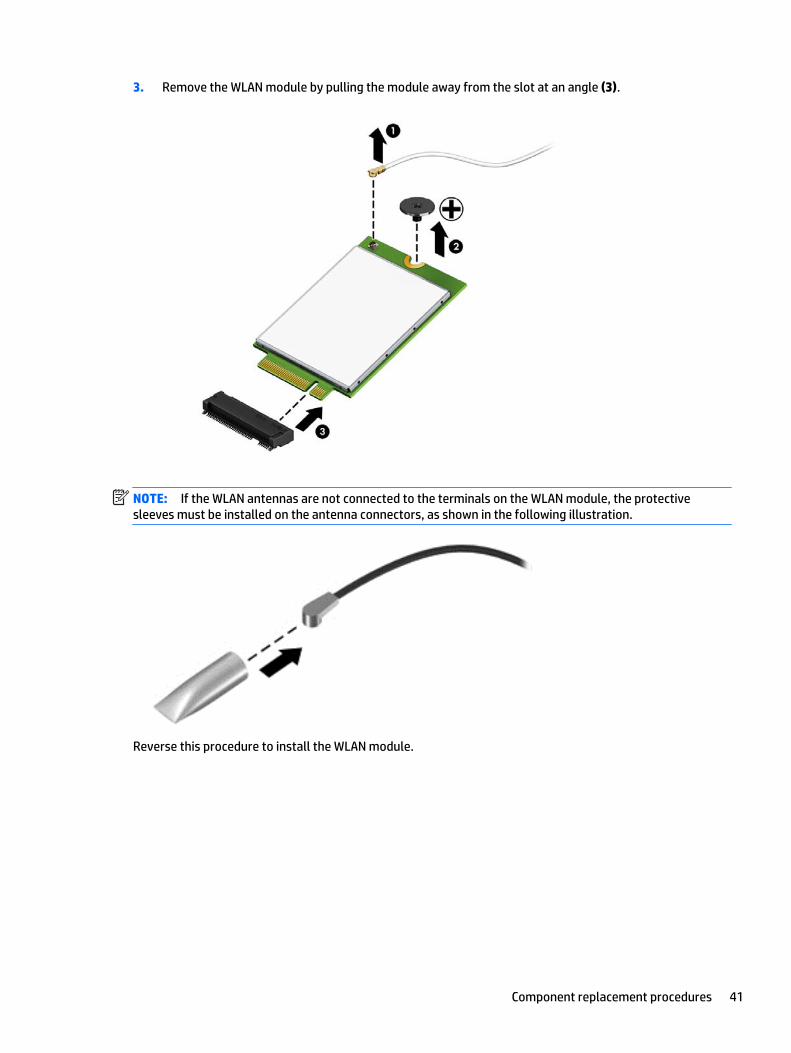
3. Remove the WLAN module by pulling the module away from the slot at an angle (3).
NOTE: If the WLAN antennas are not connected to the terminals on the WLAN module, the protectivesleeves must be installed on the antenna connectors, as shown in the following illustration.
Reverse this procedure to install the WLAN module.
Component replacement procedures 41
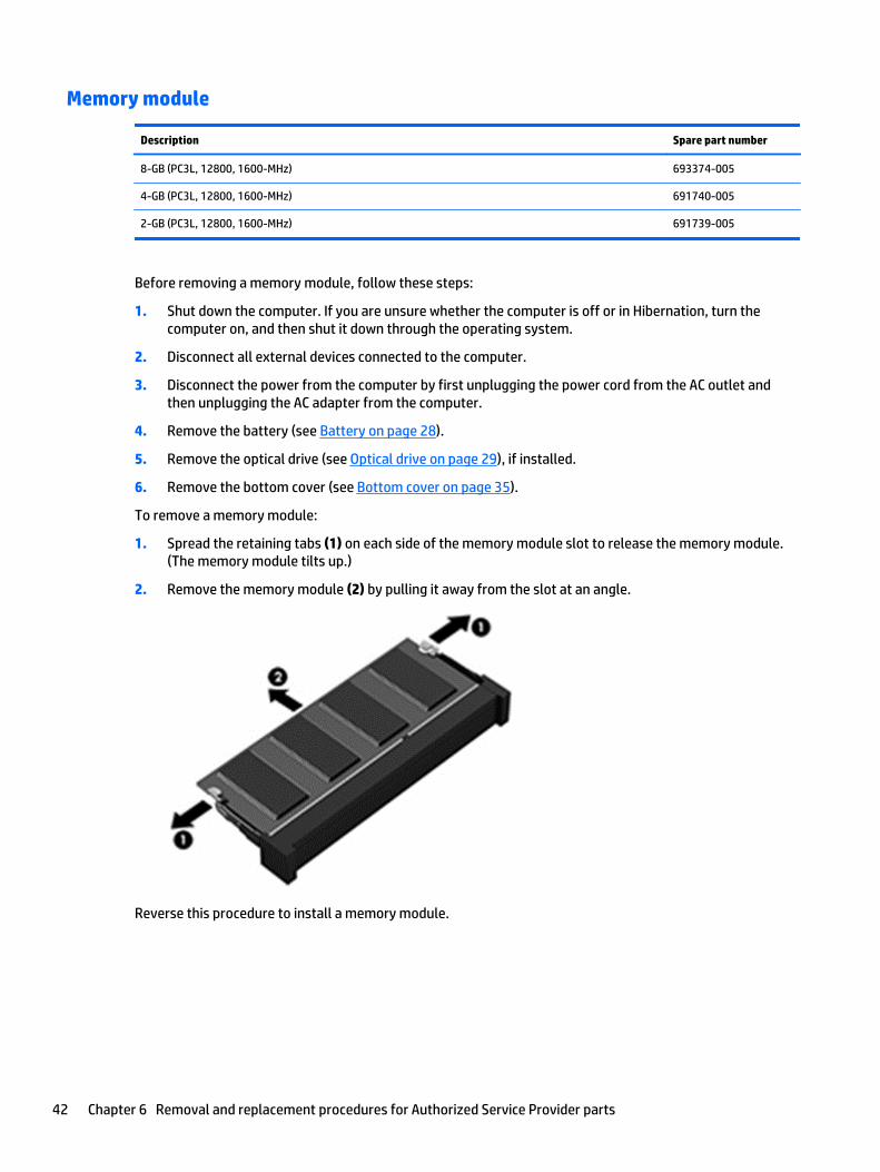
Memory module
Description Spare part number
8-GB (PC3L, 12800, 1600-MHz) 693374-005
4-GB (PC3L, 12800, 1600-MHz) 691740-005
2-GB (PC3L, 12800, 1600-MHz) 691739-005
Before removing a memory module, follow these steps:
1. Shut down the computer. If you are unsure whether the computer is off or in Hibernation, turn thecomputer on, and then shut it down through the operating system.
2. Disconnect all external devices connected to the computer.
3. Disconnect the power from the computer by first unplugging the power cord from the AC outlet andthen unplugging the AC adapter from the computer.
4. Remove the battery (see Battery on page 28).
5. Remove the optical drive (see Optical drive on page 29), if installed.
6. Remove the bottom cover (see Bottom cover on page 35).
To remove a memory module:
1. Spread the retaining tabs (1) on each side of the memory module slot to release the memory module.(The memory module tilts up.)
2. Remove the memory module (2) by pulling it away from the slot at an angle.
Reverse this procedure to install a memory module.
42 Chapter 6 Removal and replacement procedures for Authorized Service Provider parts

RTC battery
Description Spare part number
RTC battery 759981-001
Before removing the RTC battery, follow these steps:
1. Shut down the computer. If you are unsure whether the computer is off or in Hibernation, turn thecomputer on, and then shut it down through the operating system.
2. Disconnect all external devices connected to the computer.
3. Disconnect the power from the computer by first unplugging the power cord from the AC outlet andthen unplugging the AC adapter from the computer.
4. Remove the battery (see Battery on page 28).
5. Remove the optical drive (see Optical drive on page 29), if installed.
6. Remove the bottom cover (see Bottom cover on page 35).
To remove the RTC battery:
▲ Using a thin tool or screwdriver, disengage the battery from the socket (1), and then remove the battery(2).
Reverse this procedure to install the RTC battery.
Component replacement procedures 43
USB board
Description Spare part number
USB board (includes cable) 813953-001
Before removing the USB board, follow these steps:
1. Shut down the computer. If you are unsure whether the computer is off or in Hibernation, turn thecomputer on, and then shut it down through the operating system.
2. Disconnect all external devices connected to the computer.
3. Disconnect the power from the computer by first unplugging the power cord from the AC outlet andthen unplugging the AC adapter from the computer.
4. Remove the battery (see Battery on page 28).
5. Remove the optical drive (see Optical drive on page 29), if installed.
6. Remove the bottom cover (see Bottom cover on page 35).
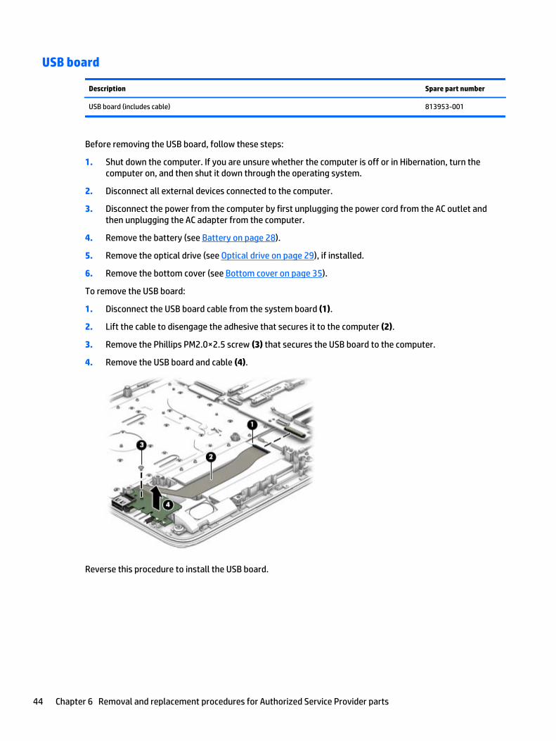
To remove the USB board:
1. Disconnect the USB board cable from the system board (1).
2. Lift the cable to disengage the adhesive that secures it to the computer (2).
3. Remove the Phillips PM2.0×2.5 screw (3) that secures the USB board to the computer.
4. Remove the USB board and cable (4).
Reverse this procedure to install the USB board.
44 Chapter 6 Removal and replacement procedures for Authorized Service Provider parts

Speakers
Description Spare part number
Speakers (includes left and right speakers and cable) 813965-001
Before removing the speakers, follow these steps:
1. Shut down the computer. If you are unsure whether the computer is off or in Hibernation, turn thecomputer on, and then shut it down through the operating system.
2. Disconnect all external devices connected to the computer.
3. Disconnect the power from the computer by first unplugging the power cord from the AC outlet andthen unplugging the AC adapter from the computer.
4. Remove the battery (see Battery on page 28).
5. Remove the optical drive (see Optical drive on page 29), if installed.
6. Remove the bottom cover (see Bottom cover on page 35).
To remove the speakers:
1. Disconnect the speaker cable from the system board (1).
2. Remove the cable from the routing path (2), and then lift up and remove the speakers from thecomputer (3).
NOTE: The speakers are not secured with screws. Note the rubber gaskets (4) that help secure thespeakers to the computer. When installing the speakers, make sure the gaskets are installed correctly.
Reverse this procedure to install the speakers.
Component replacement procedures 45

Heat sink assembly
NOTE: The heat sink assembly spare part kit includes replacement thermal materials.
Description Spare part number
Heat sink for use in models with discrete graphics memory 813948-001
Heat sink for use in models with UMA 813947-001
NOTE: To properly ventilate the computer, allow at least 7.6 cm (3.0 in) of clearance on the left side of thecomputer. The computer uses an electric fan for ventilation. The fan is controlled by a temperature sensorand is designed to turn on automatically when high temperature conditions exist. These conditions areaffected by high external temperatures, system power consumption, power management/batteryconservation configurations, battery fast charging, and software requirements. Exhaust air is displacedthrough the ventilation grill located on the left side of the computer.
Before removing the heat sink assembly, follow these steps:
1. Shut down the computer. If you are unsure whether the computer is off or in Hibernation, turn thecomputer on, and then shut it down through the operating system.
2. Disconnect all external devices connected to the computer.
3. Disconnect the power from the computer by first unplugging the power cord from the AC outlet andthen unplugging the AC adapter from the computer.
4. Remove the battery (see Battery on page 28).
5. Remove the optical drive (see Optical drive on page 29), if installed.
6. Remove the bottom cover (see Bottom cover on page 35).
To remove the heat sink assembly:
1. Refer to the following heat sink removal image that matches your computer.
2. Loosen the screws on the heat sink that secure the heat sink assembly to the system board.
46 Chapter 6 Removal and replacement procedures for Authorized Service Provider parts
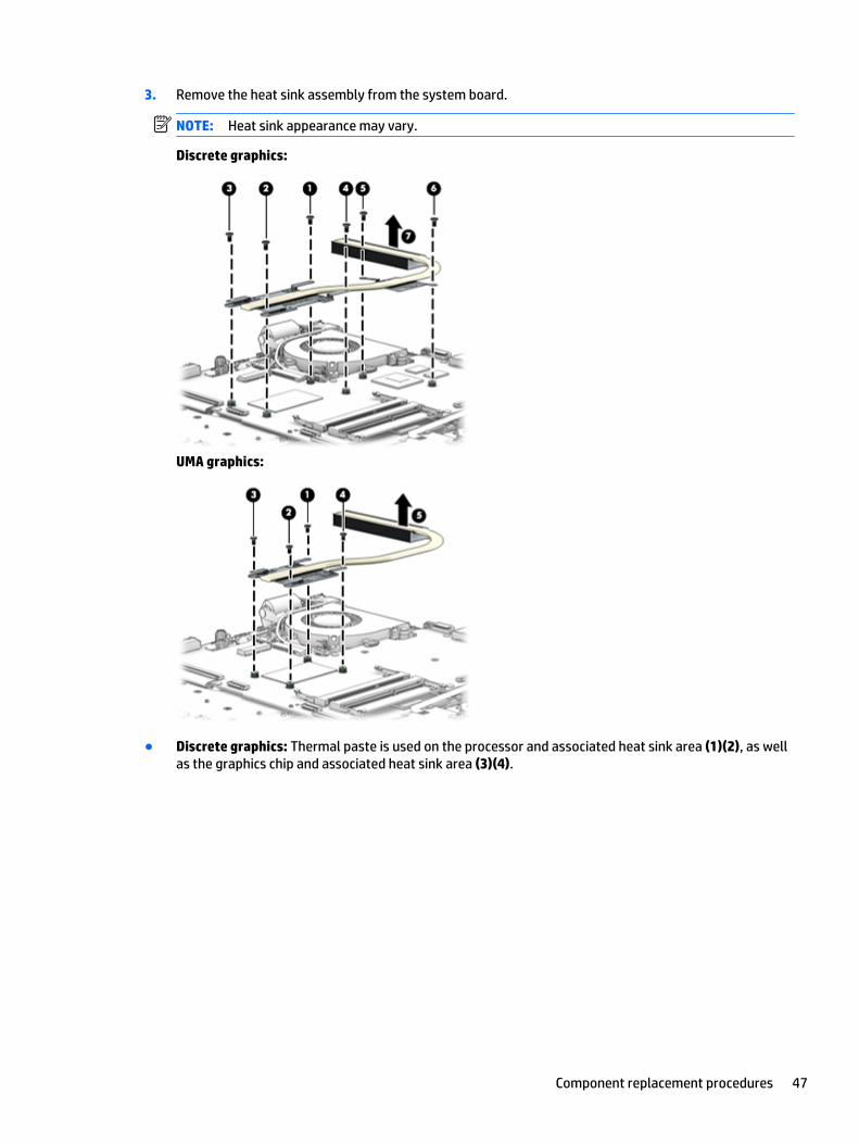
3. Remove the heat sink assembly from the system board.
NOTE: Heat sink appearance may vary.
Discrete graphics:
UMA graphics:
● Discrete graphics: Thermal paste is used on the processor and associated heat sink area (1)(2), as wellas the graphics chip and associated heat sink area (3)(4).
Component replacement procedures 47

● UMA graphics: Thermal paste is used on the heat sink (1) and the processor (2).
Reverse this procedure to reassemble and install the heat sink assembly.
48 Chapter 6 Removal and replacement procedures for Authorized Service Provider parts

Fan
Description Spare part number
Fan 813946-001
NOTE: To properly ventilate the computer, allow at least 7.6 cm (3.0 in) of clearance on the left side of thecomputer. The computer uses an electric fan for ventilation. The fan is controlled by a temperature sensorand is designed to turn on automatically when high temperature conditions exist. These conditions areaffected by high external temperatures, system power consumption, power management/batteryconservation configurations, battery fast charging, and software requirements. Exhaust air is displacedthrough the ventilation grill located on the left side of the computer.
Before removing the fan/heat sink assembly, follow these steps:
1. Shut down the computer. If you are unsure whether the computer is off or in Hibernation, turn thecomputer on, and then shut it down through the operating system.
2. Disconnect all external devices connected to the computer.
3. Disconnect the power from the computer by first unplugging the power cord from the AC outlet andthen unplugging the AC adapter from the computer.
4. Remove the battery (see Battery on page 28).
5. Remove the optical drive (see Optical drive on page 29), if installed.
6. Remove the bottom cover (see Bottom cover on page 35).
To remove the fan:
1. Disconnect the fan cable (1) from the system board.
2. Remove the two Phillips PM2.5×6.0 screws (2) that secure the fan to the computer.
3. Remove the fan from the computer (3).
Reverse this procedure to install the fan.
Component replacement procedures 49
TouchPad button board
Description Spare part number
TouchPad button board (includes bracket and cables) 813954-001
Before removing the TouchPad button board, follow these steps:
1. Shut down the computer. If you are unsure whether the computer is off or in Hibernation, turn thecomputer on, and then shut it down through the operating system.
2. Disconnect all external devices connected to the computer.
3. Disconnect the power from the computer by first unplugging the power cord from the AC outlet andthen unplugging the AC adapter from the computer.
4. Remove the battery (see Battery on page 28).
5. Remove the optical drive (see Optical drive on page 29), if installed.
6. Remove the bottom cover (see Bottom cover on page 35).
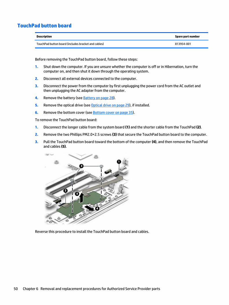
To remove the TouchPad button board:
1. Disconnect the longer cable from the system board (1) and the shorter cable from the TouchPad (2).
2. Remove the two Phillips PM2.0×2.5 screws (3) that secure the TouchPad button board to the computer.
3. Pull the TouchPad button board toward the bottom of the computer (4), and then remove the TouchPadand cables (5).
Reverse this procedure to install the TouchPad button board and cables.
50 Chapter 6 Removal and replacement procedures for Authorized Service Provider parts

System board
NOTE: The system board spare part kit includes replacement thermal materials.
Description Spare partnumber
System board (includes replacement thermal materials):
All system boards use the following part numbers:
xxxxxx-001: Without the Windows 8.1 operating system
xxxxxx-501: Windows 8.1 Standard
xxxxxx-601: Windows 8.1 Professional
For use in HP Notebook PC models:
Discrete graphics memory; Non-touch screen models:
● AMD A8-7410 processor and 2 GB of discrete graphics memory 813971-xxx
● AMD A6-6310 processor and 1 GB of discrete graphics memory 818487-xxx
UMA graphics memory; non-touch screen models:
● AMD A8-7410 processor 813969-xxx
● AMD A6-6310 processor 813967-xxx
● AMD E1-6015 processor 813966-xxx
UMA graphics memory, touch screen models:
● AMD A8-7410 processor 813970-xxx
● AMD A6-6310 processor 813968-xxx
For use in HP 255 G4 models:
UMA graphics memory
● AMD A8-7410 processor 814612-xxx
● AMD A6-6310 processor 814611-xxx
● AMD E1-6015 processor 814610-xxx
Before removing the system board, follow these steps:
1. Shut down the computer. If you are unsure whether the computer is off or in Hibernation, turn thecomputer on, and then shut it down through the operating system.
2. Disconnect all external devices connected to the computer.
3. Disconnect the power from the computer by first unplugging the power cord from the AC outlet andthen unplugging the AC adapter from the computer.
4. Remove the battery (see Battery on page 28).
5. Remove the optical drive (see Optical drive on page 29), if installed.
Component replacement procedures 51

6. Remove the bottom cover (see Bottom cover on page 35).
7. Remove the hard drive (see Hard drive on page 38).
NOTE: When replacing the system board, be sure that the following components are removed from thedefective system board and installed on the replacement system board:
● WLAN module (see WLAN module on page 40)
● Memory module (see Memory module on page 42)
To remove the system board:
1. Position the computer upright, and then disconnect the following cables from the system board:
(1): USB board cable
(2): Optical drive connector cable
(3): Keyboard cable
(4): Power connector cable
(5): Display cable
(6): Power button board cable
(7): TouchPad button board cable
(8): Speaker cable
2. Remove the six Phillips PM2.5×2.5 screws (1) that secure the system board to the computer.
52 Chapter 6 Removal and replacement procedures for Authorized Service Provider parts
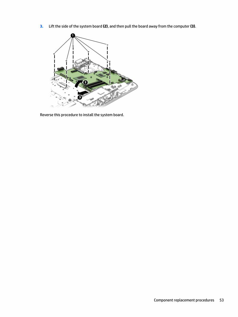
3. Lift the side of the system board (2), and then pull the board away from the computer (3).
Reverse this procedure to install the system board.
Component replacement procedures 53

Display assembly
This section describes removing the display assembly and disassembling display subcomponents.
If you only need to remove the display bezel, webcam/microphone module, or display panel, you do not needto remove the entire display assembly from the computer. See Display subcomponents (bezel, webcam,panel) on page 31 for more information about removing the display subcomponents that do not require thatyou remove the entire display assembly from the computer.
Description Spare part number
Raw display panel (39.6-cm [15.6-in], HD, WLED, BrightView)
For use in models without a touch screen 813959-001
For use in models with a touch screen 813961-001
Antenna (includes wireless antenna cable and transceiver) 813923-001
Display bezel (includes Mylar screw covers)
For use in HP Notebook models 813941-001
For use in HP 255 G4 Notebook models 814615-001
Display cable
For use in non-touch screen models (includes display panel cable and webcam/microphone cable) 813943-001
For use in touch screen models (includes display panel cable and webcam/microphone cable) 813944-001
Display enclosure for use in HP Notebook models without a touch screen
Black models 813925-001
Red models 813929-001
White silver models 813926-001
Turbo silver models 813930-001
Blue models 813927-001
Purple models 813928-001
Display enclosure for use in HP Notebook models with a touch screen
Black models 813936-001
Red models 813934-001
White silver models 813931-001
Turbo silver models 813935-001
Blue models 813932-001
Purple models 813933-001
Display enclosure for use in HP 255 G4 Notebook models 814616-001
Hinges (left and right) 813950-001
Webcam/microphone module
For use in HP Notebook models 813972-001
For use in HP 255 G4 Notebook models 814613-001
54 Chapter 6 Removal and replacement procedures for Authorized Service Provider parts
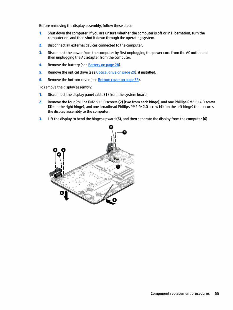
Before removing the display assembly, follow these steps:
1. Shut down the computer. If you are unsure whether the computer is off or in Hibernation, turn thecomputer on, and then shut it down through the operating system.
2. Disconnect all external devices connected to the computer.
3. Disconnect the power from the computer by first unplugging the power cord from the AC outlet andthen unplugging the AC adapter from the computer.
4. Remove the battery (see Battery on page 28).
5. Remove the optical drive (see Optical drive on page 29), if installed.
6. Remove the bottom cover (see Bottom cover on page 35).
To remove the display assembly:
1. Disconnect the display panel cable (1) from the system board.
2. Remove the four Phillips PM2.5×5.0 screws (2) (two from each hinge), and one Phillips PM2.5×4.0 screw(3) (on the right hinge), and one broadhead Phillips PM2.0×2.0 screw (4) (on the left hinge) that securesthe display assembly to the computer.
3. Lift the display to bend the hinges upward (5), and then separate the display from the computer (6).
Component replacement procedures 55

4. Use the following image to determine proper cable routing around the hinge.
(1): Display cable routing path
(2): Webcam cable routing path
(3): Antenna cable routing path
If it is necessary to replace any of the display assembly subcomponents:
1. To remove the display bezel:
a. Flex the inside of the top edge (1), the left and right edges (2), and the bottom edge (3) of thedisplay bezel until the bezel disengages from the display enclosure.
b. Remove the display bezel (4).
NOTE: In this procedure, the display will NOT be connected to the computer, as shown in thefollowing image.
2. To remove the webcam/microphone module:
a. Position the display assembly with the top edge toward you.
b. Disconnect the cable (1) from the module.
56 Chapter 6 Removal and replacement procedures for Authorized Service Provider parts
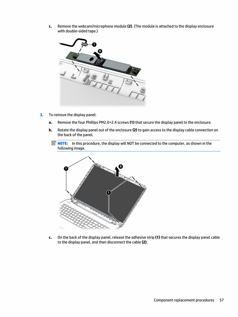
c. Remove the webcam/microphone module (2). (The module is attached to the display enclosurewith double-sided tape.)
3. To remove the display panel:
a. Remove the four Phillips PM2.0×2.4 screws (1) that secure the display panel to the enclosure.
b. Rotate the display panel out of the enclosure (2) to gain access to the display cable connection onthe back of the panel.
NOTE: In this procedure, the display will NOT be connected to the computer, as shown in thefollowing image.
c. On the back of the display panel, release the adhesive strip (1) that secures the display panel cableto the display panel, and then disconnect the cable (2).
Component replacement procedures 57

d. Remove the display panel from the computer (3).
NOTE: In this procedure, the display will NOT be connected to the computer, as shown in thefollowing image.
4. To remove the display hinges:
a. Remove the eight Phillips PM2.5×3.5 screws (1) (four per hinge) that secure the hinges tothe display enclosure.
b. Remove the display hinges (2).
58 Chapter 6 Removal and replacement procedures for Authorized Service Provider parts

5. To remove the wireless antenna cables and transceivers, release the wireless antenna cables from theclips built into the display enclosure (1), and then remove the cables (2).
6. To remove the display/webcam cable, remove the cable from the clips built into the display enclosure(1), and then remove the cable from the display enclosure (2).
7. If replacing the display enclosure, be sure that the subcomponents (including the webcam/microphonemodule, the antenna receivers, and all associated cables and hardware) are transferred to the newenclosure.
Reverse this procedure to reassemble and install the display assembly.
Component replacement procedures 59
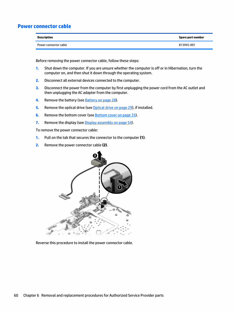
Power connector cable
Description Spare part number
Power connector cable 813945-001
Before removing the power connector cable, follow these steps:
1. Shut down the computer. If you are unsure whether the computer is off or in Hibernation, turn thecomputer on, and then shut it down through the operating system.
2. Disconnect all external devices connected to the computer.
3. Disconnect the power from the computer by first unplugging the power cord from the AC outlet andthen unplugging the AC adapter from the computer.
4. Remove the battery (see Battery on page 28).
5. Remove the optical drive (see Optical drive on page 29), if installed.
6. Remove the bottom cover (see Bottom cover on page 35).
7. Remove the display (see Display assembly on page 54).
To remove the power connector cable:
1. Pull on the tab that secures the connector to the computer (1).
2. Remove the power connector cable (2).
Reverse this procedure to install the power connector cable.
60 Chapter 6 Removal and replacement procedures for Authorized Service Provider parts

Power button board
Description Spare part number
Power button board (includes cable) 813955-001
Before removing the power button board, follow these steps:
1. Shut down the computer. If you are unsure whether the computer is off or in Hibernation, turn thecomputer on, and then shut it down through the operating system.
2. Disconnect all external devices connected to the computer.
3. Disconnect the power from the computer by first unplugging the power cord from the AC outlet andthen unplugging the AC adapter from the computer.
4. Remove the battery (see Battery on page 28).
5. Remove the optical drive (see Optical drive on page 29), if installed.
6. Remove the bottom cover (see Bottom cover on page 35).
7. Remove the display (see Display assembly on page 54).
To remove the power button board:
1. Remove the Phillips PM2.0×2.5 screw (1) that secures the power button board to the top cover.
2. Remove the power button board and cable from the computer (2).
Reverse this procedure to install the power button board and cable.
Component replacement procedures 61

62 Chapter 6 Removal and replacement procedures for Authorized Service Provider parts
7 Using Setup Utility (BIOS) in Windows 8.1
Setup Utility, or Basic Input/Output System (BIOS), controls communication between all the input and outputdevices on the system (such as disk drives, display, keyboard, mouse, and printer). Setup Utility (BIOS)includes settings for the types of devices installed, the startup sequence of the computer, and the amount ofsystem and extended memory.
Starting Setup Utility (BIOS)CAUTION: Use extreme care when making changes in Setup Utility (BIOS). Errors can prevent the computerfrom operating properly.
▲ Turn on or restart the computer, quickly press esc, and then press f10.
Updating the BIOSUpdated versions of the BIOS may be available on the HP website.
Most BIOS updates on the HP website are packaged in compressed files called SoftPaqs.
Some download packages contain a file named Readme.txt, which contains information regarding installingand troubleshooting the file.
Determining the BIOS version
To determine whether available BIOS updates contain later BIOS versions than the one currently installed onthe computer, you need to know the version of the system BIOS that is installed.
BIOS version information (also known as ROM date and System BIOS) can be revealed from the Start screen bytyping support, selecting the HP Support Assistant app, selecting My computer, and then selectingSystem Information, or by using Setup Utility (BIOS).
1. Start Setup Utility (BIOS) (see Starting Setup Utility (BIOS) on page 63).
2. Select Main, and then make note of your BIOS version.
3. Select Exit, select Exit Discarding Changes, and then follow the on-screen instructions.
Downloading a BIOS update
CAUTION: To reduce the risk of damage to the computer or an unsuccessful installation, download andinstall a BIOS update only when the computer is connected to reliable external power using the AC adapter.Do not download or install a BIOS update while the computer is running on battery power, docked in anoptional docking device, or connected to an optional power source. During the download and installation,follow these instructions:
● Do not disconnect power from the computer by unplugging the power cord from the AC outlet.
● Do not shut down the computer or initiate Sleep.
● Do not insert, remove, connect, or disconnect any device, cable, or cord.
NOTE: If your computer is connected to a network, consult the network administrator before installing anysoftware updates, especially system BIOS updates.
Starting Setup Utility (BIOS) 63

1. From the Start screen, type support, and then select the HP Support Assistant app.
‒ or –
From the Windows desktop, click the question mark icon in the notification area, at the far right of thetaskbar.
2. Click Updates and tune-ups, and then click Check for HP updates now.
3. Follow the on-screen instructions.
4. At the download area, follow these steps:
a. Identify the most recent BIOS update and compare it to the BIOS version currently installed onyour computer. If the update is more recent than your BIOS, make a note of the date, name, orother identifier. You may need this information to locate the update later, after it has beendownloaded to your hard drive.
b. Follow the on-screen instructions to download your selection to the hard drive.
If the update is more recent than your BIOS, make a note of the path to the location on your harddrive where the BIOS update is downloaded. You will need to access this path when you are readyto install the update.
BIOS installation procedures vary. Follow any instructions that appear on the screen after the download iscomplete. If no instructions appear, follow these steps:
1. From the Start screen, type file, and then select File Explorer.
‒ or –
From the Windows desktop, right-click the Start button, and then select File Explorer.
2. Click your hard drive designation. The hard drive designation is typically Local Disk (C:).
3. Using the hard drive path you recorded earlier, open the folder on your hard drive that contains theupdate.
4. Double-click the file that has an .exe extension (for example, filename.exe).
The BIOS installation begins.
5. Complete the installation by following the on-screen instructions.
NOTE: After a message on the screen reports a successful installation, you can delete the downloaded filefrom your hard drive.
64 Chapter 7 Using Setup Utility (BIOS) in Windows 8.1
8 Using Setup Utility (BIOS) in Windows 7
Setup Utility, or Basic Input/Output System (BIOS), controls communication between all the input and outputdevices on the system (such as disk drives, display, keyboard, mouse, and printer). Setup Utility (BIOS)includes settings for the types of devices installed, the startup sequence of the computer, and the amount ofsystem and extended memory.
Starting Setup Utility (BIOS)▲ To start Setup Utility (BIOS), turn on or restart the computer, quickly press esc, and then press f10.
NOTE: Use extreme care when making changes in Setup Utility (BIOS). Errors can prevent the computerfrom operating properly.
Updating the BIOSUpdated versions of the BIOS may be available on the HP website.
Most BIOS updates on the HP website are packaged in compressed files called SoftPaqs.
Some download packages contain a file named Readme.txt, which contains information regarding installingand troubleshooting the file.
Determining the BIOS version
To determine whether available BIOS updates contain later BIOS versions than those currently installed onthe computer, you need to know the version of the system BIOS currently installed.
BIOS version information (also known as ROM date and System BIOS) can be displayed by pressing fn+esc (ifyou are already in Windows) or by using Setup Utility (BIOS).
1. Start Setup Utility (BIOS).
2. Use the arrow keys to select Main, and then make note of your current BIOS version.
3. To exit Setup Utility (BIOS) without saving your changes, use the tab key and the arrow keys to selectExit > Exit Discarding Changes, and then press enter.
Downloading a BIOS update
CAUTION: To reduce the risk of damage to the computer or an unsuccessful installation, download andinstall a BIOS update only when the computer is connected to reliable external power using the AC adapter.Do not download or install a BIOS update while the computer is running on battery power, docked in anoptional docking device, or connected to an optional power source. During the download and installation,follow these instructions:
Do not disconnect power from the computer by unplugging the power cord from the AC outlet.
Do not shut down the computer or initiate Sleep or Hibernation.
Do not insert, remove, connect, or disconnect any device, cable, or cord.
Starting Setup Utility (BIOS) 65
1. Select Start, type hp support assistant, and then select the HP Support Assistant program.
2. Follow the on-screen instructions to identify your computer and access the BIOS update you want todownload.
3. At the download area, follow these steps:
a. Identify the BIOS update that is later than the BIOS version currently installed on your computer.Make a note of the date, name, or other identifier. You may need this information to locate theupdate later, after it has been downloaded to your hard drive.
b. Follow the on-screen instructions to download your selection to the hard drive.
Make a note of the path to the location on your hard drive where the BIOS update is downloaded.You will need to access this path when you are ready to install the update.
NOTE: If you connect your computer to a network, consult the network administrator before installingany software updates, especially system BIOS updates.
BIOS installation procedures vary. Follow any instructions that are displayed on the screen after thedownload is complete. If no instructions are displayed, follow these steps:
1. Open Windows Explorer by selecting Start > Computer.
2. Double-click your hard drive designation. The hard drive designation is typically Local Disk (C:).
3. Using the hard drive path you recorded earlier, open the folder on your hard drive that contains theupdate.
4. Double-click the file that has an .exe extension (for example, filename.exe).
The BIOS installation begins.
5. Complete the installation by following the on-screen instructions.
NOTE: After a message on the screen reports a successful installation, you can delete the downloaded filefrom your hard drive.
66 Chapter 8 Using Setup Utility (BIOS) in Windows 7

9 Backing up, restoring, and recovering inWindows 8.1
This chapter provides information about the following processes. The information in the chapter is standardprocedure for most models.
● Creating recovery media and backups
● Restoring and recovering your system
For additional information, refer to the HP Support Assistant.
▲ From the Start screen, type support, and then select the HP Support Assistant app.
- or -
From the Windows desktop, click the question mark icon in the notification area, at the far right of thetaskbar.
Creating recovery media and backupsThe following methods of creating recovery media and backups are available on select models only. Choosethe available method according to your computer model.
● Use HP Recovery Manager after you successfully set up the computer to create HP Recovery media. Thisstep creates a backup of the HP Recovery partition on the computer. The backup can be used to reinstallthe original operating system in cases where the hard drive is corrupted or has been replaced. Forinformation on creating recovery media, see Creating HP Recovery media (select models only)on page 67. For information on the recovery options that are available using the recovery media, seeRecovering using HP Recovery Manager on page 69.
● Use Windows tools to create system restore points and create backups of personal information.
For more information, see Using Windows tools on page 68.
NOTE: If storage is 32 GB or less, Microsoft System Restore is disabled by default.
Creating HP Recovery media (select models only)
IMPORTANT: If your computer does not list a Recovery Media Creation option, you can obtain recoverymedia for your system from support. See the Worldwide Telephone Numbers booklet included with thecomputer. You can also find contact information from the HP website. Go to http://www.hp.com/support,select your country or region, and follow the on-screen instructions.
HP Recovery Manager is a software program that allows you to create recovery media after you successfullyset up the computer. HP Recovery media can be used to perform system recovery if the hard drive becomescorrupted. System recovery reinstalls the original operating system and the software programs installed atthe factory and then configures the settings for the programs. HP Recovery media can also be used tocustomize the system or restore the factory image if you replace the hard drive.
Creating recovery media and backups 67

● Only one set of recovery media can be created. Handle these recovery tools carefully, and keep them ina safe place.
● HP Recovery Manager examines the computer and determines the required storage capacity for themedia that will be required.
● To create recovery discs, your computer must have an optical drive with DVD writer capability, and youmust use only high-quality blank DVD-R, DVD+R, DVD-R DL, or DVD+R DL discs. Do not use rewritablediscs such as CD±RW, DVD±RW, double-layer DVD±RW, or BD-RE (rewritable Blu-ray) discs; they are notcompatible with HP Recovery Manager software. Or, instead, you can use a high-quality blank USB flashdrive.
● If your computer does not include an integrated optical drive with DVD writer capability, but you wouldlike to create DVD recovery media, you can use an external optical drive (purchased separately) tocreate recovery discs, or you can obtain recovery discs for your computer from support. See theWorldwide Telephone Numbers booklet included with the computer. You can also find contactinformation from the HP website. Go to http://www.hp.com/support, select your country or region, andfollow the on-screen instructions. If you use an external optical drive, it must be connected directly to aUSB port on the computer; the drive cannot be connected to a USB port on an external device, such as aUSB hub.
● Be sure that the computer is connected to AC power before you begin creating the recovery media.
● The creation process can take an hour or more. Do not interrupt the creation process.
● If necessary, you can exit the program before you have finished creating all of the recovery DVDs. HPRecovery Manager will finish burning the current DVD. The next time you start HP Recovery Manager,you will be prompted to continue, and the remaining discs will be burned.
To create HP Recovery media:
1. From the Start screen, type recovery, and then select HP Recovery Manager.
2. Select Recovery Media Creation, and then follow the on-screen instructions.
If you ever need to recover the system, see Recovering using HP Recovery Manager on page 69.
Using Windows toolsYou can create system restore points and create backups of personal information using Windows tools.
NOTE: If storage is 32 GB or less, Microsoft System Restore is disabled by default.
▲ From the Start screen, type help, and then select Help and Support.
‒ or –
From the Windows desktop, click the question mark icon in the notification area, at the far right of thetaskbar.
For more information and steps, see Help and Support.
Restore and recoveryThere are several options for recovering your system. Choose the method that best matches your situationand level of expertise:
IMPORTANT: Not all methods are available on all models.
68 Chapter 9 Backing up, restoring, and recovering in Windows 8.1

● Windows offers several options for restoring from backup, refreshing the computer, and resetting thecomputer to its original state. For more information see Help and Support.
▲ From the Start screen, type support, and then select the HP Support Assistant app.
- or -
From the Windows desktop, click the question mark icon in the notification area, at the far right ofthe taskbar.
● If you need to correct a problem with a preinstalled application or driver, use the Drivers andApplications Reinstall option of HP Recovery Manager to reinstall the individual application or driver.
▲ From the Start screen, type recovery, select HP Recovery Manager, select Drivers andApplications Reinstall, and then follow the on-screen instructions.
● On select models, if you want to reset your computer using a minimized image, you can choose the HPMinimized Image Recovery option from the HP Recovery partition or HP Recovery media. MinimizedImage Recovery installs only drivers and hardware-enabling applications. Other applications included inthe image continue to be available for installation through the Drivers and Applications Reinstall optionin HP Recovery Manager.
For more information, see Recovering using HP Recovery Manager on page 69.
● If you want to recover the Windows partition to original factory content, you can choose the SystemRecovery option from the HP Recovery partition (select models only) or use the HP Recovery media. Formore information, see Recovering using HP Recovery Manager on page 69. If you have not alreadycreated recovery media, see Creating HP Recovery media (select models only) on page 67.
● On select models, if you want to recover the computer's original factory partition and content , or if youhave replaced the hard drive, you can use the Factory Reset option of HP Recovery media. For moreinformation, see Recovering using HP Recovery Manager on page 69.
● On select models, if you want to remove the recovery partition to reclaim hard drive space, HP RecoveryManager offers the Remove Recovery Partition option.
For more information, see Removing the HP Recovery partition (select models only) on page 71.
Recovering using HP Recovery Manager
HP Recovery Manager software allows you to recover the computer to its original factory state by using theHP Recovery media that you either created or that you obtained from support, or by using the HP Recoverypartition (select models only). If you have not already created recovery media, see Creating HP Recoverymedia (select models only) on page 67.
What you need to know before you get started
● HP Recovery Manager recovers only software that was installed at the factory. For software notprovided with this computer, you must either download the software from the manufacturer's websiteor reinstall the software from the media provided by the manufacturer.
IMPORTANT: Recovery through HP Recovery Manager should be used as a final attempt to correctcomputer issues.
● HP Recovery media must be used if the computer hard drive fails. If you have not already createdrecovery media, see Creating HP Recovery media (select models only) on page 67.
Restore and recovery 69
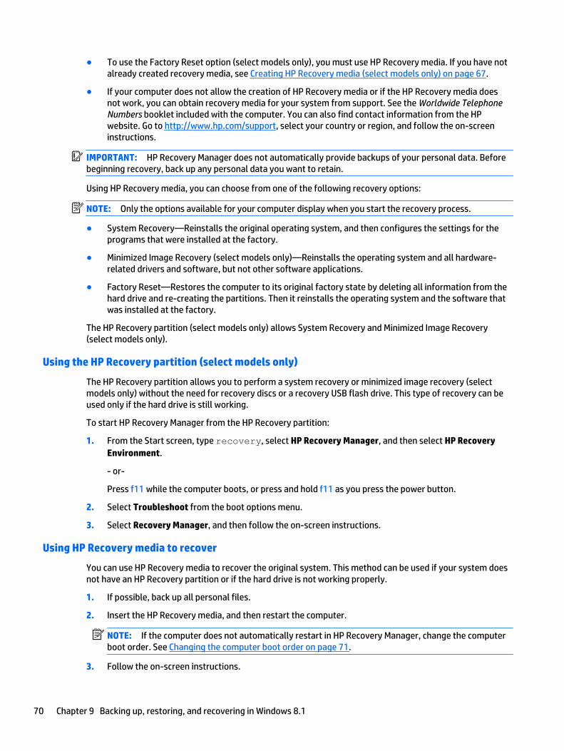
● To use the Factory Reset option (select models only), you must use HP Recovery media. If you have notalready created recovery media, see Creating HP Recovery media (select models only) on page 67.
● If your computer does not allow the creation of HP Recovery media or if the HP Recovery media doesnot work, you can obtain recovery media for your system from support. See the Worldwide TelephoneNumbers booklet included with the computer. You can also find contact information from the HPwebsite. Go to http://www.hp.com/support, select your country or region, and follow the on-screeninstructions.
IMPORTANT: HP Recovery Manager does not automatically provide backups of your personal data. Beforebeginning recovery, back up any personal data you want to retain.
Using HP Recovery media, you can choose from one of the following recovery options:
NOTE: Only the options available for your computer display when you start the recovery process.
● System Recovery—Reinstalls the original operating system, and then configures the settings for theprograms that were installed at the factory.
● Minimized Image Recovery (select models only)—Reinstalls the operating system and all hardware-related drivers and software, but not other software applications.
● Factory Reset—Restores the computer to its original factory state by deleting all information from thehard drive and re-creating the partitions. Then it reinstalls the operating system and the software thatwas installed at the factory.
The HP Recovery partition (select models only) allows System Recovery and Minimized Image Recovery(select models only).
Using the HP Recovery partition (select models only)
The HP Recovery partition allows you to perform a system recovery or minimized image recovery (selectmodels only) without the need for recovery discs or a recovery USB flash drive. This type of recovery can beused only if the hard drive is still working.
To start HP Recovery Manager from the HP Recovery partition:
1. From the Start screen, type recovery, select HP Recovery Manager, and then select HP RecoveryEnvironment.
- or-
Press f11 while the computer boots, or press and hold f11 as you press the power button.
2. Select Troubleshoot from the boot options menu.
3. Select Recovery Manager, and then follow the on-screen instructions.
Using HP Recovery media to recover
You can use HP Recovery media to recover the original system. This method can be used if your system doesnot have an HP Recovery partition or if the hard drive is not working properly.
1. If possible, back up all personal files.
2. Insert the HP Recovery media, and then restart the computer.
NOTE: If the computer does not automatically restart in HP Recovery Manager, change the computerboot order. See Changing the computer boot order on page 71.
3. Follow the on-screen instructions.
70 Chapter 9 Backing up, restoring, and recovering in Windows 8.1

Changing the computer boot order
If your computer does not restart in HP Recovery Manager, you can change the computer boot order, which isthe order of devices listed in BIOS where the computer looks for startup information. You can change theselection for an optical drive or a USB flash drive.
To change the boot order:
1. Insert the HP Recovery media.
2. Start Computer Setup:
▲ Turn on or restart the computer, quickly press esc, and then press f9 for boot options.
3. Select the optical drive or USB flash drive from which you want to boot.
4. Follow the on-screen instructions.
Removing the HP Recovery partition (select models only)
HP Recovery Manager software allows you to remove the HP Recovery partition to free up hard drive space.
IMPORTANT: After you remove the HP Recovery partition, you can no longer use the Windows Refreshoption or the Windows option to remove everything and reinstall Windows. In addition, you will not be able toperform System Recovery or Minimized Image Recovery from the HP Recovery partition. So before youremove the Recovery partition, create HP Recovery media; see Creating HP Recovery media (select modelsonly) on page 67.
Follow these steps to remove the HP Recovery partition:
1. From the Start screen, type recovery, and then select HP Recovery Manager.
2. Select Remove Recovery Partition, and then follow the on-screen instructions.
Restore and recovery 71

72 Chapter 9 Backing up, restoring, and recovering in Windows 8.1

10 Backing up, restoring, and recovering inWindows 7
Your computer includes tools provided by the operating system and HP to help you safeguard yourinformation and retrieve it if ever needed.
Creating backups1. Use HP Recovery Manager to create recovery media immediately after you set up the working
computer.
2. As you add hardware and software programs, create system restore points.
3. As you add photos, video, music, and other personal files, create a backup of your system and personalinformation.
Creating recovery media to recover the original system
After you successfully set up the computer, you should create recovery discs or a recovery flash drive usingHP Recovery Manager. You will need these recovery discs or recovery flash drive to perform a systemrecovery should the hard drive become corrupted. A system recovery reinstalls the original operating system,and then configures the settings for the default programs.
What you need to know
● Only one set of recovery media can be created. Handle these recovery tools carefully, and keep them ina safe place.
● HP Recovery Manager examines the computer and determines the required storage capacity for theflash drive or the number of blank DVD discs that will be required.
Use DVD-R, DVD+R, DVD-R DL, DVD+R DL discs or a flash drive. Do not use rewriteable discs such as CD±RW, DVD±RW, double-layer DVD±RW, and BD-RE (rewritable Blu-ray) discs; they are not compatiblewith HP Recovery Manager software.
● If your computer does not include an integrated optical drive, you can use an optional external opticaldrive (purchased separately) to create recovery discs, or you can obtain recovery discs for yourcomputer from the HP website. If you use an external optical drive, it must be connected directly to aUSB port on the computer, not to a USB port on an external device, such as a USB hub.
● Be sure that the computer is connected to AC power before you begin creating the recovery media.
● The creation process can take up to an hour or more. Do not interrupt the creation process.
● Store the recovery media in a safe location, separate from the computer.
● If necessary, you can exit the program before you have finished creating the recovery media. The nexttime you open HP Recovery Manager, you will be prompted to continue the process.
Creating backups 73

Creating the recovery media
1. Select Start and type recovery in the search field. Select HP Recovery Manager from the list. Allowthe action to continue, if prompted.
2. Click Recovery Media Creation.
3. Follow the on-screen instructions to continue.
To recover, see Recovering the original system using HP Recovery Manager on page 76.
Creating system restore points
A system restore point is a snapshot of certain hard drive contents saved by Windows System Restore at aspecific time. A restore point contains information such as registry settings that Windows uses. Restoring toa previous restore point allows you to reverse changes that have been made to the system since the restorepoint was created.
Restoring to an earlier system restore point does not affect data files saved or emails created since the lastrestore point, but it does affect software you may have installed.
For example, if you download a photo from a digital camera and then restore the computer to the state it wason the previous day, the photo remains on the computer.
However, if you install photo viewing software and then restore your computer to the state it was on theprevious day, the software will be uninstalled, and you won't be able to use it.
What you need to know
● If you restore to a restore point and then change your mind, you can undo the restoration.
● You should create system restore points:
◦ Before you add or change software or hardware
◦ Periodically, whenever the computer is running normally
● System Restore also saves shadow copies of files that have been changed since the last restore pointwas created. For more information about using shadow copies to restore, see Help and Support.
Creating a system restore point
1. Select Start > Control Panel > System and Security > System.
2. In the left pane, click System Protection.
3. Click the System Protection tab.
4. Click Create, and follow the on-screen instructions.
To restore, see Restoring to a previous system restore point on page 76.
Backing up system and personal information
Your computer stores information that is important to you, such as files, emails, and photos, and you willwant to keep that information even if you download a virus or the system stops working properly. Howcompletely you are able to recover your files depends on how recent your backup is. As you add newsoftware and data files, you should create backups on a regular basis.
74 Chapter 10 Backing up, restoring, and recovering in Windows 7

Tips for a successful backup
● Number backup discs before inserting them into the optical drive.
● Store personal files in the Documents, Music, Pictures, and Videos libraries, and back up these foldersperiodically.
● Save customized settings in a window, toolbar, or menu bar by taking a screen shot of your settings.The screen shot can be a time-saver if you have to re-enter your preferences.
To create a screen shot:
1. Display the screen you want to save.
2. Copy the screen image:
To copy only the active window, press alt+prt sc.
To copy the entire screen, press prt sc.
3. Open a word-processing document or graphics editing program, and then select Edit > Paste. Thescreen image is added to the document.
4. Save and print the document.
What you need to know
● You can back up your information to an optional external hard drive, a flash drive, a network drive, ordiscs.
● Connect the computer to AC power during backups.
● Allow enough time for the backup. Depending on files sizes, it may take more than an hour.
● Verify the amount of free space on your backup storage device before you back up.
● You should back up:
◦ Before adding or changing software or hardware.
◦ Before the computer is repaired or restored.
◦ On a regular schedule to be sure you have recent copies of personal information.
◦ After you add many files—for example, if you saved videos from a birthday party.
◦ Before using antivirus software to remove a malicious program.
◦ After adding information that is hard to replace, such as pictures, videos, music, project files, ordata records.
Creating a backup using Windows Backup and Restore
Windows allows you to back up files using Windows Backup and Restore. You can select the level you want toback up, from individual folders to drives. The backups are compressed to save space. To back up:
1. Select Start > Control Panel > System and Security > Backup and Restore.
2. Follow the on-screen instructions to schedule and create a backup.
NOTE: Windows includes the User Account Control feature to improve the security of the computer. Youmay be prompted for your permission or password for tasks such as installing software, running utilities, orchanging Windows settings. See Help and Support for more information.
To restore, see Restoring specific files using Windows Backup and Restore on page 76.
Creating backups 75

Restore and recovery
Restoring to a previous system restore point
Sometimes installing a software program causes your computer or Windows to behave unpredictably.Usually uninstalling the software fixes the problems. If uninstalling does not fix the problems, you canrestore the computer to a previous system restore point (created at an earlier date and time).
To restore to a previous system restore point, when the computer was running correctly:
1. Select Start > Control Panel > System and Security > System.
2. In the left pane, click System Protection.
3. Click the System Protection tab.
4. Click System Restore, and follow the on-screen instructions.
Restoring specific files
If files are accidentally deleted from the hard disk and they can no longer be restored from the Recycle Bin, orif files become corrupt, restoring specific files is useful. Restoring specific files is also useful if you everchoose to recover the original system using HP Recovery Manager. You can only restore specific files that youhave backed up before.
Restoring specific files using Windows Backup and Restore
Windows allows you to restore files that were backed up using Windows Backup and Restore:
1. Select Start > Control Panel > System and Security > Backup and Restore.
2. Follow the on-screen instructions to restore your backup.
NOTE: Windows includes the User Account Control feature to improve the security of the computer. Youmay be prompted for your permission or password for tasks such as installing software, running utilities, orchanging Windows settings. See Help and Support for more information.
Recovering the original system using HP Recovery Manager
HP Recovery Manager software allows you to repair or recover the computer to its original factory state.
What you need to know
● HP Recovery Manager recovers only software that was installed at the factory. For software notprovided with this computer, you must either download the software from the manufacturer's websiteor reinstall the software from the disc provided by the manufacturer.
● A system recovery should be used as a final attempt to correct computer issues. If you have not alreadytried restore points (see Restoring to a previous system restore point on page 76) and partial restores(see Restoring specific files on page 76), try them before using HP Recovery Manager to recover yoursystem.
● A system recovery must be performed if the computer hard drive fails or if all attempts to correct anyfunctional computer issues fail.
76 Chapter 10 Backing up, restoring, and recovering in Windows 7
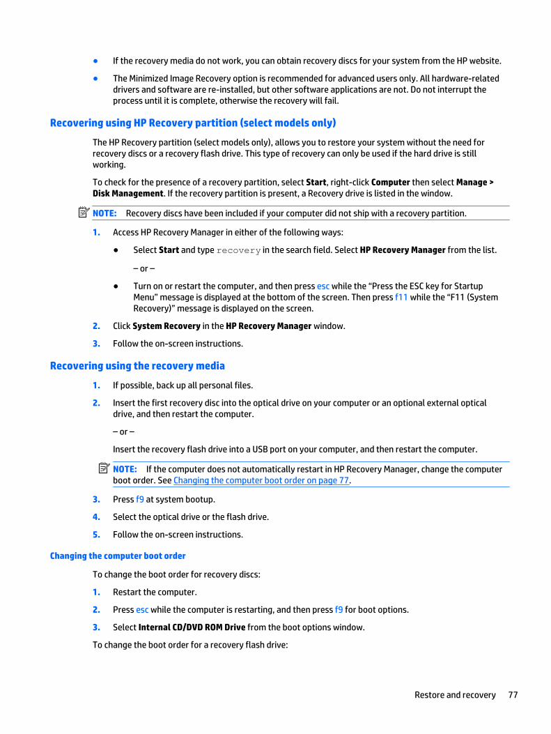
● If the recovery media do not work, you can obtain recovery discs for your system from the HP website.
● The Minimized Image Recovery option is recommended for advanced users only. All hardware-relateddrivers and software are re-installed, but other software applications are not. Do not interrupt theprocess until it is complete, otherwise the recovery will fail.
Recovering using HP Recovery partition (select models only)
The HP Recovery partition (select models only), allows you to restore your system without the need forrecovery discs or a recovery flash drive. This type of recovery can only be used if the hard drive is stillworking.
To check for the presence of a recovery partition, select Start, right-click Computer then select Manage >Disk Management. If the recovery partition is present, a Recovery drive is listed in the window.
NOTE: Recovery discs have been included if your computer did not ship with a recovery partition.
1. Access HP Recovery Manager in either of the following ways:
● Select Start and type recovery in the search field. Select HP Recovery Manager from the list.
– or –
● Turn on or restart the computer, and then press esc while the “Press the ESC key for StartupMenu” message is displayed at the bottom of the screen. Then press f11 while the “F11 (SystemRecovery)” message is displayed on the screen.
2. Click System Recovery in the HP Recovery Manager window.
3. Follow the on-screen instructions.
Recovering using the recovery media
1. If possible, back up all personal files.
2. Insert the first recovery disc into the optical drive on your computer or an optional external opticaldrive, and then restart the computer.
– or –
Insert the recovery flash drive into a USB port on your computer, and then restart the computer.
NOTE: If the computer does not automatically restart in HP Recovery Manager, change the computerboot order. See Changing the computer boot order on page 77.
3. Press f9 at system bootup.
4. Select the optical drive or the flash drive.
5. Follow the on-screen instructions.
Changing the computer boot order
To change the boot order for recovery discs:
1. Restart the computer.
2. Press esc while the computer is restarting, and then press f9 for boot options.
3. Select Internal CD/DVD ROM Drive from the boot options window.
To change the boot order for a recovery flash drive:
Restore and recovery 77

1. Insert the flash drive into a USB port.
2. Restart the computer.
3. Press esc while the computer is restarting, and then press f9 for boot options.
4. Select the flash drive from the boot options window.
78 Chapter 10 Backing up, restoring, and recovering in Windows 7
11 Using HP PC Hardware Diagnostics (UEFI)
HP PC Hardware Diagnostics is a Unified Extensible Firmware Interface (UEFI) that allows you to rundiagnostic tests to determine whether the computer hardware is functioning properly. The tool runs outsidethe operating system so that it can isolate hardware failures from issues that are caused by the operatingsystem or other software components.
To start HP PC Hardware Diagnostics (UEFI):
1. Start Setup Utility:
▲ Turn on or restart the computer, quickly press esc.
2. Press or tap f2.
The BIOS searches 3 places for the diagnostic tools, in the following order:
a. Connected USB drive
NOTE: To download the HP PC Hardware Diagnostics (UEFI) tool to a USB drive, see DownloadingHP PC Hardware Diagnostics (UEFI) to a USB device on page 79.
b. Hard drive
c. BIOS
3. When the diagnostic tool opens, use the keyboard arrow keys to select the type of diagnostic test youwant to run, and then follow the on-screen instructions.
NOTE: If you need to stop a diagnostic test, press or tap esc.
Downloading HP PC Hardware Diagnostics (UEFI) to a USB deviceNOTE: Instructions for downloading HP PC Hardware Diagnostics (UEFI) are provided in English only.
There are two options to download HP PC Hardware Diagnostics to a USB device.
Download the latest UEFI version:
1. Go to http://hp.com/go/techcenter/pcdiags. The HP PC Diagnostics home page is displayed.
2. Click the Download link in the HP PC Hardware Diagnostics section, and then select Run.
Download any version of UEFI for a specific product:
1. Go to http://www.hp.com/support, and then select your country. The HP Support page is displayed.
2. Click Drivers & Downloads.
3. In the text box, enter the product name, and then click Go.
– or –
Click Find Now to let HP automatically detect your product.
4. Select your computer model, and then select your operating system.
5. In the Diagnostic section, follow the on-screen instructions to select and download the UEFI version youwant.
Downloading HP PC Hardware Diagnostics (UEFI) to a USB device 79

80 Chapter 11 Using HP PC Hardware Diagnostics (UEFI)

12 Specifications
Computer specifications
Metric U.S.
Dimensions (touch models)
Depth 254.6 mm 10.02 in
Width 384.3 mm 15.13 in
Height 24.3 mm 0.96 in
Weight
3 cell battery
4 cell battery
1994 g
2040 g
4.40 lb
4.50 lb
Input power
Operating voltage and current 19.5 V dc @ 3.33 A – 65 W
19.5 V dc @ 2.31 A – 45 W
Temperature
Operating 5°C to 35°C 41°F to 95°F
Nonoperating -20°C to 60°C -4°F to 140°F
Relative humidity (noncondensing)
Operating 10% to 90%
Nonoperating 5% to 95%
Maximum altitude (unpressurized)
Operating -15 m to 3,048 m -50 ft to 10,000 ft
Nonoperating -15 m to 12,192 m -50 ft to 40,000 ft
NOTE: Applicable product safety standards specify thermal limits for plastic surfaces. The device operates well within this range oftemperatures.
Computer specifications 81
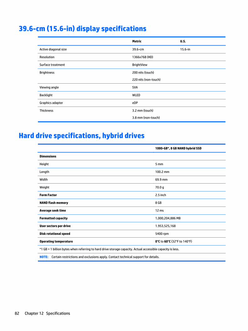
39.6-cm (15.6-in) display specifications
Metric U.S.
Active diagonal size 39.6-cm 15.6-in
Resolution 1366x768 (HD)
Surface treatment BrightView
Brightness 200 nits (touch)
220 nits (non-touch)
Viewing angle SVA
Backlight WLED
Graphics adapter eDP
Thickness 3.2 mm (touch)
3.8 mm (non-touch)
Hard drive specifications, hybrid drives
1000-GB*, 8 GB NAND hybrid SSD
Dimensions
Height 5 mm
Length 100.2 mm
Width 69.9 mm
Weight 70.0 g
Form Factor 2.5 inch
NAND flash memory 8 GB
Average seek time 12 ms
Formatted capacity 1,000,204,886 MB
User sectors per drive 1.953,525,168
Disk rotational speed 5400 rpm
Operating temperature 0°C to 60°C (32°F to 140°F)
*1 GB = 1 billion bytes when referring to hard drive storage capacity. Actual accessible capacity is less.
NOTE: Certain restrictions and exclusions apply. Contact technical support for details.
82 Chapter 12 Specifications
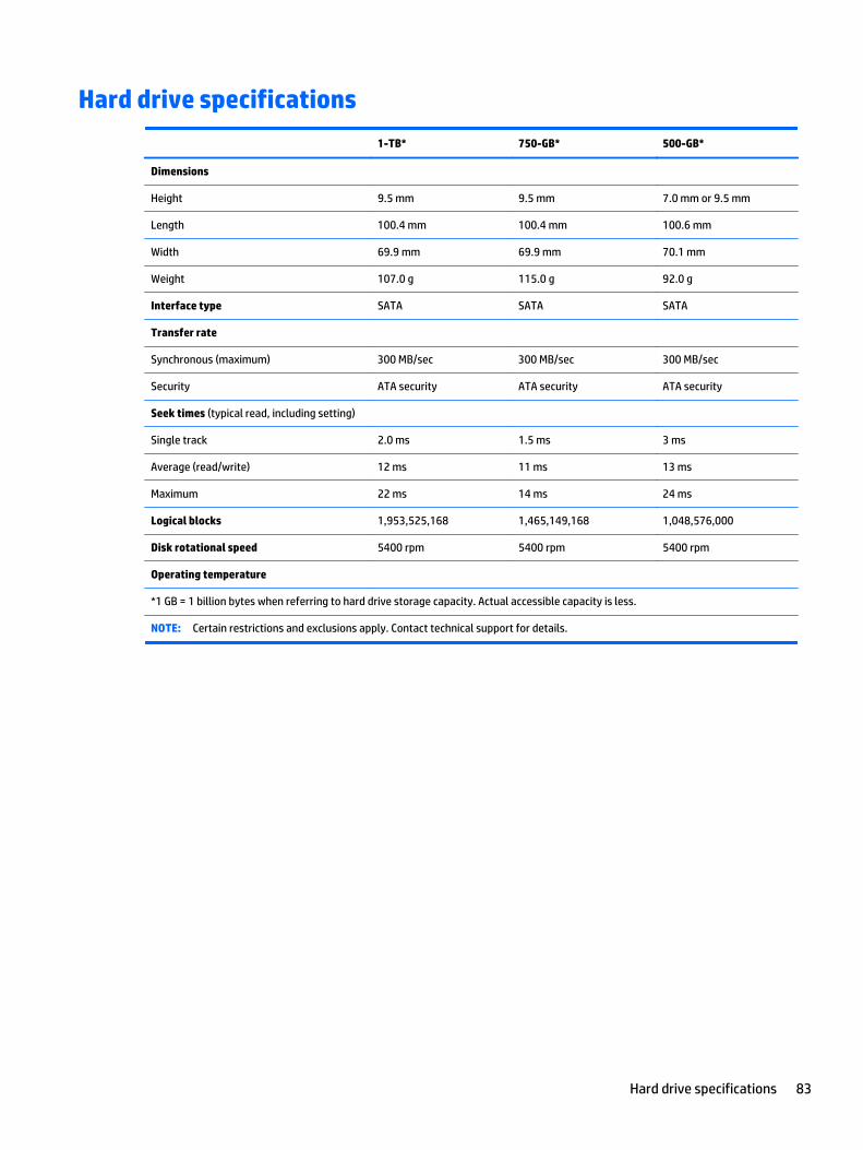
Hard drive specifications
1-TB* 750-GB* 500-GB*
Dimensions
Height 9.5 mm 9.5 mm 7.0 mm or 9.5 mm
Length 100.4 mm 100.4 mm 100.6 mm
Width 69.9 mm 69.9 mm 70.1 mm
Weight 107.0 g 115.0 g 92.0 g
Interface type SATA SATA SATA
Transfer rate
Synchronous (maximum) 300 MB/sec 300 MB/sec 300 MB/sec
Security ATA security ATA security ATA security
Seek times (typical read, including setting)
Single track 2.0 ms 1.5 ms 3 ms
Average (read/write) 12 ms 11 ms 13 ms
Maximum 22 ms 14 ms 24 ms
Logical blocks 1,953,525,168 1,465,149,168 1,048,576,000
Disk rotational speed 5400 rpm 5400 rpm 5400 rpm
Operating temperature
*1 GB = 1 billion bytes when referring to hard drive storage capacity. Actual accessible capacity is less.
NOTE: Certain restrictions and exclusions apply. Contact technical support for details.
Hard drive specifications 83
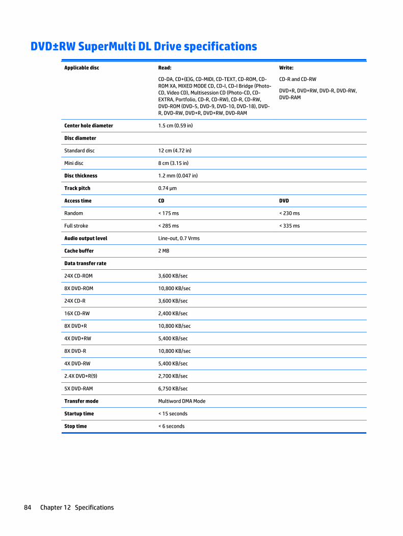
DVD±RW SuperMulti DL Drive specifications
Applicable disc Read:
CD-DA, CD+(E)G, CD-MIDI, CD-TEXT, CD-ROM, CD-ROM XA, MIXED MODE CD, CD-I, CD-I Bridge (Photo-CD, Video CD), Multisession CD (Photo-CD, CD-EXTRA, Portfolio, CD-R, CD-RW), CD-R, CD-RW,DVD-ROM (DVD-5, DVD-9, DVD-10, DVD-18), DVD-R, DVD-RW, DVD+R, DVD+RW, DVD-RAM
Write:
CD-R and CD-RW
DVD+R, DVD+RW, DVD-R, DVD-RW,DVD-RAM
Center hole diameter 1.5 cm (0.59 in)
Disc diameter
Standard disc 12 cm (4.72 in)
Mini disc 8 cm (3.15 in)
Disc thickness 1.2 mm (0.047 in)
Track pitch 0.74 μm
Access time CD DVD
Random < 175 ms < 230 ms
Full stroke < 285 ms < 335 ms
Audio output level Line-out, 0.7 Vrms
Cache buffer 2 MB
Data transfer rate
24X CD-ROM 3,600 KB/sec
8X DVD-ROM 10,800 KB/sec
24X CD-R 3,600 KB/sec
16X CD-RW 2,400 KB/sec
8X DVD+R 10,800 KB/sec
4X DVD+RW 5,400 KB/sec
8X DVD-R 10,800 KB/sec
4X DVD-RW 5,400 KB/sec
2.4X DVD+R(9) 2,700 KB/sec
5X DVD-RAM 6,750 KB/sec
Transfer mode Multiword DMA Mode
Startup time < 15 seconds
Stop time < 6 seconds
84 Chapter 12 Specifications
13 Statement of Volatility
The purpose of this document is to provide general information regarding non-volatile memory in industry-standards based HP Business Notebook PC systems and provide general instructions for restoringnonvolatile memory that can contain personal data after the system has been powered off and the hard drivehas been removed.
HP Business Notebook PC products that use Intel®-based or AMD®-based system boards contain volatile DDRmemory. The amount of nonvolatile memory present in the system depends upon the system configuration.Intel-based and AMD-based system boards contain nonvolatile memory subcomponents as originallyshipped from HP assuming that no subsequent modifications have been made to the system and assumingthat no applications, features, or functionality have been added to or installed on the system.
Following system shutdown and removal of all power sources from an HP Business Notebook PC system,personal data can remain on volatile system memory (DIMMs) for a finite period of time and will also remainin nonvolatile memory. The steps below will remove personal data from the notebook PC, including thenonvolatile memory found in Intel-based and AMD-based system boards. Some of these steps are disclosedin the Maintenance & Service Guides available for HP PC products available on the product support pages atwww.hp.com.
1. Follow steps (a) through (I) below to restore the nonvolatile memory that can contain personal data.Restoring or reprogramming nonvolatile memory that does not store personal data is neither necessarynor recommended.
a. Enter BIOS (F10) Setup by powering on the system and pressing F10 when prompted near thebottom of the display, or press the ESC key to display the start up menu, then press F10 . If thesystem has a BIOS administrator password, enter the password at the prompt.
b. Select the File menu, then Restore Defaults.
c. Select the System Configuration menu, then Restore Security Defaults.
d. If an asset or ownership tag is set, select the Security menu and scroll down to the Utilities menu.Select System IDs, and then select the tag that has been set. Press the spacebar once to clear thetag, then press Enter to return to the prior menu.
e. If a DriveLock password is set, select the Security menu, scroll down to DriveLock, then selectDriveLock password. Select the desired hard drive. Click Disable protection, enter the existingmaster DriveLock password, then press Enter to confirm and return to the prior menu. Repeat thisprocedure if more than one hard drive has a DriveLock password.
f. If an Automatic DriveLock password is set, select the Security menu, scroll down to AutomaticDriveLock, then select the desired hard drive and disable protection. Repeat this procedure ifmore than one hard drive has an Automatic DriveLock password.
g. Select the File menu, then Reset BIOS Security to factory default. Click yes at the warningmessage.
h. Select the File menu, then Save Changes and Exit.
i. Reboot the system. If the system has a Trusted Platform Module (TPM) and/or fingerprint sensor,one or two prompts will appear. One to clear the TPM and the other to Reset Fingerprint Sensor;press F1 to accept or F2 to reject.
If the HP notebook model number ends in a ‘p’ or ‘w’ and includes Intel® Centrino with VProTM,reboot the PC and enter BIOS Setup by pressing F10 when prompted. Select System
85

Configuration, then AMT Options. Then select Unconfigure AMT on next boot. Select Save thenYes. Select the File menu, and then select Save Changes and Exit. Reboot the system and confirmthat you want to unconfigure AMT.
j. If the optional Intel® Anti-Theft Technology (AT) was activated, contact the provider to deactivateit.
k. If the optional Absolute® Software Computrace® management and tracking service was activatedon the notebook PC, contact the provider to deactivate it.
l. Remove all power and system batteries for at least 24 hours.
2. Remove and retain the storage drive or clear the contents of the drive.
a. Hard Disk Drive (HDD)
Clear the HDD contents by using the HP Disk Sanitizer® utility or a third party application that,ideally, is U.S. Department of Defense (DOD) 5220.22-M approved.
To run HP Disk Sanitizer, enter BIOS Setup by powering on the system and pressing F10 whenprompted near the bottom of the display, or press ESC to display the start up menu, then pressF10. Select the Security menu and scroll down to the Utilities menu. Select Disk Sanitizer andselect the desired drive. For a higher level of protection, select Optimum.
NOTE: This process will take a long time, and the amount of time varies based on the hard drivecapacity.
b. Solid State Drive (SSD)
Clear the SSD contents by using the BIOS Setup Secure Erase command option, or by using a thirdparty utility designed to erase data from an SSD. To run Secure Erase, enter BIOS Setup bypowering on the system and pressing F10 when prompted near the bottom of the display. Selectthe Security menu and scroll down to the Utilities menu. Select Secure Erase and select thedesired hard drive.
86 Chapter 13 Statement of Volatility

Non-volatile memory usage
Non VolatileMemory Type
Amount(Size)
Does thismemorystorecustomerdata?
Does thismemoryretain datawhen power isremoved?
What is thepurpose ofthis memory?
How is data input intothis memory?
How is this memorywrite protected?
Real Time Clock(RTC) batterybacked-upCMOSconfigurationmemory (CMOS)
256 Bytes No Yes Stores systemdate and timeand limitedkeyboardcontrollerdata.
Using the F10 Setup utilityor changing theMicrosoft® Windows®date & time.
This memory is notwrite-protected. HPrecommendspassword protectingthe F10 Setup utility.
Controller (NIC)EEPROM
64 Kbytes(notcustomeraccessible)
No Yes Store NICconfigurationand NICfirmware.
Using a utility from theNIC vendor that can be runfrom DOS.
A utility is required towrite data to thismemory and isavailable from NICvendor. Writing datato this ROM in aninappropriate mannerwill render the NICnonfunctional.
Keyboard ROM 64 Kbytes(notcustomeraccessible)
No Yes Storesfirmware code(keyboard,mouse, &batterymanagement).
Programmed at thefactory. Code is updatedwhen the system BIOS isupdated.
A utility is required forwriting data to thismemory and isavailable on the HPwebsite. Writing datato this ROM in aninappropriate mannercan render the PCnonfunctional.
DIMM SerialPresenceDetect (SPD)configurationdata
256 Bytesper memorymodule,128 Bytesprogrammabl e (notcustomeraccessible)
No Yes Storesmemorymoduleinformation.
Programmed by thememory vendor.
Data cannot be writtento this memory whenthe module is installedin a PC. The specificwrite protectionmethod varies bymemory vendor.
System BIOS 4 to 5MBytes
Yes Yes Store systemBIOS code andPCconfigurationdata.
System BIOS code isprogrammed at thefactory. Code is updatedwhen the system BIOS isupdated. Configurationdata and settings areinput using the F10 setuputility or a custom utility.
A utility is required forwriting data to thismemory and isavailable on the HPwebsite. Writing datato this ROM in aninappropriate mannercan render the PCnonfunctional.
IntelManagementEngineFirmware(present only inmodels endingin a ‘p’ or ‘w’ orwith IntelCentrino Protechnology)
1.5 or5MByte
Yes Yes StoresManagementEngine Code,Settings,ProvisioningData and iAMTthird partydata store.
Management Engine Codeis programmed at thefactory. Code is updatedvia Intel secure firmwareupdate utility. UniqueProvisioning Data can beentered at the factory orby an administrator usingthe Management Engine(MEBx) setup utility. The
The Intel chipset isconfigured to enforceHW protection to blockall direct read/writeaccess to this area. AnIntel utility is requiredfor updating thefirmware. Onlyfirmware updatesdigitally signed by
Non-volatile memory usage 87
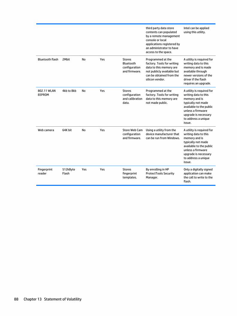
third party data storecontents can populatedby a remote managementconsole or localapplications registered byan administrator to haveaccess to the space.
Intel can be appliedusing this utility.
Bluetooth flash 2Mbit No Yes StoresBluetoothconfigurationand firmware.
Programmed at thefactory. Tools for writingdata to this memory arenot publicly available butcan be obtained from thesilicon vendor.
A utility is required forwriting data to thismemory and is madeavailable throughnewer versions of thedriver if the flashrequires an upgrade.
802.11 WLANEEPROM
4kb to 8kb No Yes Storesconfigurationand calibrationdata.
Programmed at thefactory. Tools for writingdata to this memory arenot made public.
A utility is required forwriting data to thismemory and istypically not madeavailable to the publicunless a firmwareupgrade is necessaryto address a uniqueissue.
Web camera 64K bit No Yes Store Web Camconfigurationand firmware.
Using a utility from thedevice manufacturer thatcan be run from Windows.
A utility is required forwriting data to thismemory and istypically not madeavailable to the publicunless a firmwareupgrade is necessaryto address a uniqueissue.
Fingerprintreader
512kByteFlash
Yes Yes Storesfingerprinttemplates.
By enrolling in HPProtectTools SecurityManager.
Only a digitally signedapplication can makethe call to write to theflash.
88 Chapter 13 Statement of Volatility

Questions and answers1. How can the BIOS settings be restored (returned to factory settings)?
a. Turn on or restart the computer and press F10 when prompted near the bottom of the display.
b. Select File, then select Restore defaults.
c. Follow the on-screen instructions.
d. Select File, save changes and exit, then press Enter.
2. What kind of configuration data is stored on the DIMM Serial Presence Detect (SPD) memorymodule? How would this data be written?
The DIMM SPD memory contains information about the memory module such as size, serial number,data width, speed/timing, voltage and thermal information. This information is written by the modulemanufacturer and stored on an EEPROM. This EEPROM cannot be written to when the memory module isinstalled in a PC. Third party tools do exist that can write to the EEPROM when the memory module isnot installed in a PC. There are various third party tools available to read SPD memory.
3. Does the “Firmware Hub for System BIOS” contain the BIOS program? Is this chip writable, and if sohow?
The Firmware Hub does contain the BIOS program and is writable. A utility is required to perform thewrite function.
4. In some PC systems, the Firmware Hub for System BIOS is a flash memory chip so that updates canbe written by the customer. Is this true for these BIOS chips?
Yes, they are flash memory chips.
5. What is meant by “Restore the nonvolatile memory found in Intel-based system boards”?
This relates to clearing the Real Time Clock (RTC) CMOS memory that contains PC configuration data.
6. Does resetting the CMOS configuration memory return the PC back to factory defaults?
The process of resetting the CMOS will return certain system settings to factory default but will notreset many of the system data and configuration defaults to their factory settings. To return thesesystem data and configuration defaults to factory settings, refer to question and answer 1 and followthe instructions for returning the BIOS settings to factory defaults.
Questions and answers 89

90 Chapter 13 Statement of Volatility

14 Power cord set requirements
The wide-range input feature of the computer permits it to operate from any line voltage from 100 to 120volts ac, or from 220 to 240 volts ac.
The 3-conductor power cord set included with the computer meets the requirements for use in the country orregion where the equipment is purchased.
Power cord sets for use in other countries and regions must meet the requirements of the country or regionwhere the computer is used.
Requirements for all countriesThe following requirements are applicable to all countries and regions:
● The length of the power cord set must be at least 1.5 m (5.0 ft) and no more than 2.0 m (6.5 ft).
● All power cord sets must be approved by an acceptable accredited agency responsible for evaluation inthe country or region where the power cord set will be used.
● The power cord sets must have a minimum current capacity of 10 A and a nominal voltage rating of 125or 250 V ac, as required by the power system of each country or region.
● The appliance coupler must meet the mechanical configuration of an EN 60 320/IEC 320 Standard SheetC13 connector for mating with the appliance inlet on the back of the computer.
Requirements for all countries 91

Requirements for specific countries and regions
Country/region Accredited agency Applicable note number
Argentina IRAM 1
Australia SAA 1
Austria OVE 1
Belgium CEBEC 1
Brazil ABNT 1
Canada CSA 2
Chile IMQ 1
Denmark DEMKO 1
Finland FIMKO 1
France UTE 1
Germany VDE 1
India ISI 1
Israel SII 1
Italy IMQ 1
Japan JIS 3
The Netherlands KEMA 1
New Zealand SANZ 1
Norway NEMKO 1
The People's Republic of China CCC 4
Saudi Arabia SASO 7
Singapore PSB 1
South Africa SABS 1
South Korea KTL 5
Sweden SEMKO 1
Switzerland SEV 1
Taiwan BSMI 6
Thailand TISI 1
The United Kingdom ASTA 1
The United States UL 2
1. The flexible cord must be Type HO5VV-F, 3-conductor, 0.75mm2 conductor size. Power cord set fittings (appliance coupler andwall plug) must bear the certification mark of the agency responsible for evaluation in the country or region where it will beused.
92 Chapter 14 Power cord set requirements

Country/region Accredited agency Applicable note number
2. The flexible cord must be Type SVT/SJT or equivalent, No. 18 AWG, 3-conductor. The wall plug must be a two-pole groundingtype with a NEMA 5-15P (15 A, 125 V ac) or NEMA 6-15P (15 A, 250 V ac) configuration. CSA or C-UL mark. UL file number must beon each element.
3. The appliance coupler, flexible cord, and wall plug must bear a “T” mark and registration number in accordance with theJapanese Dentori Law. The flexible cord must be Type VCTF, 3-conductor, 0.75mm2 or 1.25mm2 conductor size. The wall plugmust be a two-pole grounding type with a Japanese Industrial Standard C8303 (7 A, 125 V ac) configuration.
4. The flexible cord must be Type RVV, 3-conductor, 0.75mm2 conductor size. Power cord set fittings (appliance coupler and wallplug) must bear the CCC certification mark.
5. The flexible cord must be Type H05VV-F 3X0.75mm2 conductor size. KTL logo and individual approval number must be on eachelement. Corset approval number and logo must be printed on a flag label.
6. The flexible cord must be Type HVCTF 3X1.25mm2 conductor size. Power cord set fittings (appliance coupler, cable, and wallplug) must bear the BSMI certification mark.
7. For 127 V ac, the flexible cord must be Type SVT or SJT 3 x 18 AWG, with plug NEMA 5-15P (15 A, 125 V ac), with UL and CSA or C-UL marks. For 240 V ac, the flexible cord must be Type H05VV-F 3X0.75/1.00mm2 conductor size, with plug BS 1363/A with BSIor ASTA marks.
Requirements for specific countries and regions 93

94 Chapter 14 Power cord set requirements

15 Recycling
When a non-rechargeable or rechargeable battery has reached the end of its useful life, do not dispose of thebattery in general household waste. Follow the local laws and regulations in your area for battery disposal.
HP encourages customers to recycle used electronic hardware, HP original print cartridges, and rechargeablebatteries. For more information about recycling programs, see the HP Web site at http://www.hp.com/recycle.
95

96 Chapter 15 Recycling

Index
AAC adapter/battery light 7action keys
identifying 11antenna
illustrated 20antennas
removing 59audio, product description 2audio-out (headphone)/audio-in
(microphone) jack, identifying 7
Bbackups 67, 73base enclosure
illustrated 17battery
illustrated 17removing 28
battery cover, identifying 12battery lock, identifying 12battery release latch 12BIOS
determining version 63, 65downloading an update 63, 65starting the Setup Utility 63updating 63, 65
Bluetooth label 13boot order
changing 71, 77bottom 13bottom cover
removing 35buttons
left TouchPad 8power 10right TouchPad 8
Ccables, service considerations 23caps lock light, identifying 9chipset, product description 1components
bottom 12display 5
left side 7right side 6top 8
computer major components,illustrated 15
computer specifications 81connector, power 7connectors, service considerations
23
Ddeleted files
restoring 76display assembly
illustrated 16removing 31, 54spare part numbers 16
display assembly subcomponentsillustrated 20removing 31, 54
display bezelillustrated 20removing 32, 56
display cableillustrated 20removing 58
display enclosureillustrated 20removing 59
display panelillustrated 20, 54product description 1removing 33, 57, 58
display specifications 82DVD±RW SuperMulti DL Drive
specifications 84
Eelectrostatic discharge 24equipment guidelines 26esc key, identifying 11Ethernet, product description 2external media cards 2external monitor port, identifying 7
Ffan
illustrated 17removing 49
fn key, identifying 11
Ggraphics, product description 1grounding guidelines 24guidelines
equipment 26grounding 24packaging 25transporting 25workstation 25
Hhard drive
illustrated 17, 18precautions 24product description 1removing 38specifications 82, 83
hard drive bracketillustrated 18
hard drive bracketsremoving 39
hard drive connectorremoving 39
hard drive light 6HDMI port
identifying 7heat sink assembly
illustrated 17removing 17, 46
hingesillustrated 20removing 33, 57, 58
HP PC Hardware Diagnostics (UEFI)downloading 79
HP Recovery Manager 76correcting boot problems 71starting 70
Index 97

HP Recovery mediacreating 67recovery 70
HP Recovery partitionrecovery 70removing 71
Iintegrated numeric keypad,
identifying 11internal card
product description 2internal display switch, identifying
5internal microphones, identifying 5
Jjacks
audio-out (headphone)/audio-in(microphone) 7
network 7RJ-45 (network) 7
Kkeyboard
illustrated 16product description 3
keysaction 11esc 11fn 11Windows 11
Llabels
Bluetooth 13Microsoft Certificate of
Authenticity 13regulatory 13serial number 13service 13wireless certification 13WLAN 13
latch, battery release 12lights
AC adapter/battery 7caps lock 9hard drive 6mute 9power 6RJ-45 (network) status 7
Mmass storage devices
illustrated 18precautions 24
memory card reader, identifying 6memory card, identifying 6memory module
illustrated 17product description 1removing 42
microphone 2minimized image recovery 70minimized image, creating 69model name 1mute light, identifying 9
Nnetwork jack, identifying 7
Ooperating system 3optical drive
illustrated 17, 18precautions 24product description 2removing 29specifications 84
optical drive boardillustrated 17, 37removing 37
optical drive, identifying 6original system recovery 69, 76
Ppackaging guidelines 25plastic parts, service
considerations 23pointing device 3ports
external monitor 7HDMI 7product description 2USB 2.0 6, 7USB 3.0 7
power button boardillustrated 17removing 61
power button, identifying 10power connector cable
illustrated 17removing 60
power connector, identifying 7power cord
requirements for all countries91
requirements for specificcountries and regions 92
set requirements 91power lights, identifying 6power requirements 3processor
product description 1product description
audio 2chipset 1display panel 1Ethernet 2external media cards 2graphics 1hard drive 1internal card 2keyboard 3memory module 1microphone 2operating system 3optical drive 2pointing device 3ports 2power requirements 3processor 1product name 1security 3sensor 2serviceability 3video 2wireless 2
product name 1product name and number,
computer 13
Rrecover
options 68recovering from the recovery discs
77recovering the original system 76recovery 76
discs 68, 70HP Recovery Manager 69, 76media 70starting 70
98 Index

supported discs 68system 69USB flash drive 70using HP Recovery media 68
recovery discs 73recovery media 73
creating 67creating using HP Recovery
Manager 68recovery partition
removing 71recovery, system 76regulatory information
regulatory label 13wireless certification labels 13
removal/replacementpreliminaries 23procedures 27, 31
restore points 74restoring the original system
creating recovery media 73RJ-45 (network) jack, identifying 7RJ-45 (network) status lights,
identifying 7RTC battery
illustrated 16removing 43
Ssecurity cable slot, identifying 6security, product description 3sensor, product description 2serial number 13serial number, computer 13service considerations
cables 23connectors 23plastic parts 23
service labels, locating 13serviceability, product description 3slots
memory card reader 6security cable 6
speakersidentifying 12illustrated 17removing 45
specificationscomputer 81display 82
DVD±RW SuperMulti DL Drive 84hard drive 82, 83optical drive 84
supported discs 73supported discs, recovery 68system board
removing 51spare part number 16, 51
system recovery 69, 76system restore point
creating 68system restore point, creating 67system restore points 74
creating 74
Ttools required 23TouchPad
buttons 8TouchPad button board
removing 50spare part number 17, 50
TouchPad zone, identifying 8transporting guidelines 25traveling with the computer 13
UUSB 2.0 port, identifying 6, 7USB 3.0 port, identifying 7USB board
removing 44spare part number 16
Vvents, identifying 7video, product description 2
Wwebcam
identifying 5webcam light, identifying 5webcam/microphone cable
illustrated 20removing 33, 57, 58
webcam/microphone moduleillustrated 20removing 32, 56
Windowssystem restore point 67, 68
Windows Backup and Restorerestoring files 76
Windows key, identifying 11Windows tools
using 68wireless antenna
illustrated 20wireless antennas
removing 59wireless certification label 13wireless, product description 2WLAN antennas, identifying 5WLAN device 13WLAN label 13WLAN module
illustrated 17removing 40
workstation guidelines 25
Index 99

100 Index