how to implement usb suspend/resume feature with ... · pdf filehow to implement usb...
TRANSCRIPT
© 2016 NXP B.V.
How to Implement USB Suspend/Resume Feature with MCUXpresso SDK USB Stack
1. Introduction This application note contains the USB suspend/resume and remote wakeup-related knowledge and considerations on how to use the Kinetis MCU USB module to implement this feature. The MK64 MCU, with its FS USB controller and its MCUXpresso SDK USB stack, is used as an example to illustrate the implementation details.
2. USB power scheme The USB devices connected to a PC host or an embedded host must abide by the host power budget requirements. The USB bus power is a limited resource. The USB devices (bus-powered or self-powered) must limit their power consumption from the VBUS to less than 100 mA, until they enter the configured state.
As a way to save power, when the USB devices observe no bus traffic (constant idle state) for more than 3 ms, they enter the suspend state and consume less than 2.5 mA (according to the suspend current ECN in the USB2.0 specifications).
NXP Semiconductors Document Number: AN5385
Application Note Rev. 0 , 11/2016
Contents
1. Introduction ........................................................................ 1 2. USB power scheme ............................................................ 1 3. USB bus state for suspend and resume ............................... 2
3.1. Data J and K states .................................................. 2 3.2. Idle state .................................................................. 2 3.3. Suspend state ........................................................... 3 3.4. Resume signal ......................................................... 3
4. Considerations for implementation .................................... 3 4.1. Resume signal time duration ................................... 3 4.2. Low-power mode selection ..................................... 4
5. MCUXpresso SDK USB stack implementation ................. 5 5.1. Application layer ..................................................... 7 5.2. Common controller driver layer (DCI) .................... 8 5.3. USB controller layer (KHCI) .................................. 9
6. Running the demo ............................................................ 10 6.1. USB traffic log capture ......................................... 11 6.2. USB suspend current measurement ....................... 11
7. References ........................................................................ 13 8. Revision history ............................................................... 13
USB bus state for suspend and resume
How to Implement USB Suspend/Resume Feature with MCUXpresso SDK USB Stack, Application Note, Rev. 0, 11/2016
2 NXP Semiconductors
When a USB device is in the suspend state, it still provides power to its D+ or D- pull-up resistors to keep the idle state and maintains its internal status including the address and configuration. When it is woken up by a resume signal on the USB bus, it does not need to go through the re-enumeration process.
The resume signal on the USB bus can be sent by the host as well as by the device. The remote wake-up capability enables a USB device to wake up the suspended host; for example, with a mouse connected to your laptop, you can wake up the laptop with a mouse click. The remote wakeup capability is reported in the configuration descriptor during the enumeration stage and can be enabled (or disabled) using standard USB requests.
3. USB bus state for suspend and resume The USB specification defines the bus states that correspond to the signal voltages on the USB bus. This section explains how the USB bus defines the bus state for the suspend, resume, and idle states.
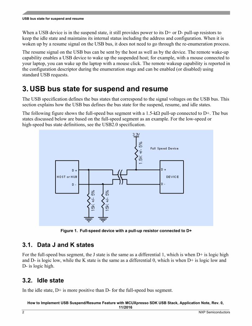
The following figure shows the full-speed bus segment with a 1.5-kΩ pull-up connected to D+. The bus states discussed below are based on the full-speed segment as an example. For the low-speed or high-speed bus state definitions, see the USB2.0 specification.
Figure 1. Full-speed device with a pull-up resistor connected to D+
3.1. Data J and K states For the full-speed bus segment, the J state is the same as a differential 1, which is when D+ is logic high and D- is logic low, while the K state is the same as a differential 0, which is when D+ is logic low and D- is logic high.
3.2. Idle state In the idle state, D+ is more positive than D- for the full-speed bus segment.
Considerations for implementation
How to Implement USB Suspend/Resume Feature with MCUXpresso SDK USB Stack, Application Note, Rev. 0, 11/2016
NXP Semiconductors 3
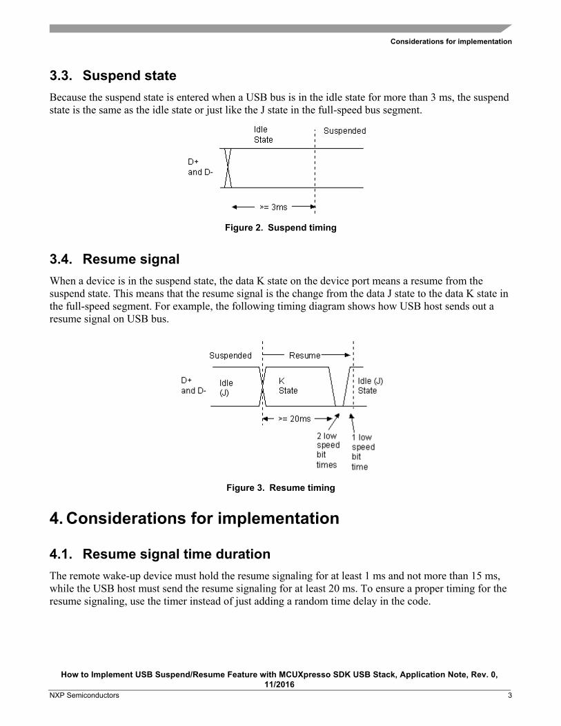
3.3. Suspend state Because the suspend state is entered when a USB bus is in the idle state for more than 3 ms, the suspend state is the same as the idle state or just like the J state in the full-speed bus segment.
Figure 2. Suspend timing
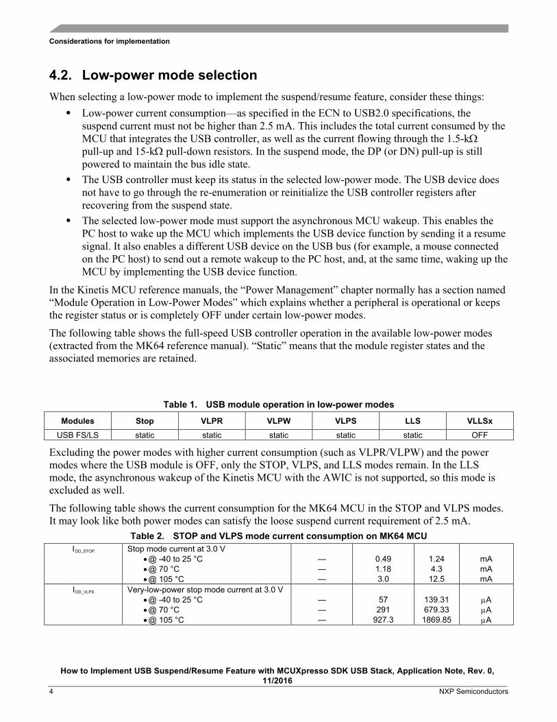
3.4. Resume signal When a device is in the suspend state, the data K state on the device port means a resume from the suspend state. This means that the resume signal is the change from the data J state to the data K state in the full-speed segment. For example, the following timing diagram shows how USB host sends out a resume signal on USB bus.
Figure 3. Resume timing
4. Considerations for implementation
4.1. Resume signal time duration The remote wake-up device must hold the resume signaling for at least 1 ms and not more than 15 ms, while the USB host must send the resume signaling for at least 20 ms. To ensure a proper timing for the resume signaling, use the timer instead of just adding a random time delay in the code.
Considerations for implementation
How to Implement USB Suspend/Resume Feature with MCUXpresso SDK USB Stack, Application Note, Rev. 0, 11/2016
4 NXP Semiconductors
4.2. Low-power mode selection When selecting a low-power mode to implement the suspend/resume feature, consider these things:
• Low-power current consumption—as specified in the ECN to USB2.0 specifications, the suspend current must not be higher than 2.5 mA. This includes the total current consumed by the MCU that integrates the USB controller, as well as the current flowing through the 1.5-kΩ pull-up and 15-kΩ pull-down resistors. In the suspend mode, the DP (or DN) pull-up is still powered to maintain the bus idle state.
• The USB controller must keep its status in the selected low-power mode. The USB device does not have to go through the re-enumeration or reinitialize the USB controller registers after recovering from the suspend state.
• The selected low-power mode must support the asynchronous MCU wakeup. This enables the PC host to wake up the MCU which implements the USB device function by sending it a resume signal. It also enables a different USB device on the USB bus (for example, a mouse connected on the PC host) to send out a remote wakeup to the PC host, and, at the same time, waking up the MCU by implementing the USB device function.
In the Kinetis MCU reference manuals, the “Power Management” chapter normally has a section named “Module Operation in Low-Power Modes” which explains whether a peripheral is operational or keeps the register status or is completely OFF under certain low-power modes.
The following table shows the full-speed USB controller operation in the available low-power modes (extracted from the MK64 reference manual). “Static” means that the module register states and the associated memories are retained.
Table 1. USB module operation in low-power modes
Modules Stop VLPR VLPW VLPS LLS VLLSx USB FS/LS static static static static static OFF
Excluding the power modes with higher current consumption (such as VLPR/VLPW) and the power modes where the USB module is OFF, only the STOP, VLPS, and LLS modes remain. In the LLS mode, the asynchronous wakeup of the Kinetis MCU with the AWIC is not supported, so this mode is excluded as well.
The following table shows the current consumption for the MK64 MCU in the STOP and VLPS modes. It may look like both power modes can satisfy the loose suspend current requirement of 2.5 mA.
Table 2. STOP and VLPS mode current consumption on MK64 MCU IDD_STOP Stop mode current at 3.0 V
• @ -40 to 25 °C • @ 70 °C • @ 105 °C
— — —
0.49 1.18 3.0
1.24 4.3
12.5
mA mA mA
IDD_VLPS Very-low-power stop mode current at 3.0 V • @ -40 to 25 °C • @ 70 °C • @ 105 °C
— — —
57
291 927.3
139.31 679.33
1869.85
µA µA µA
MCUXpresso SDK USB stack implementation
How to Implement USB Suspend/Resume Feature with MCUXpresso SDK USB Stack, Application Note, Rev. 0, 11/2016
NXP Semiconductors 5
However, the suspend current is the total current consumed by the MCU, which implements the USB device as well as the current flowing through the pull-up and pull-down resistors on DP/DN. The USB device may work in a wider temperature range and with other peripherals functioning as well, apart from the USB module in the STOP/VLPS mode (for example, ADC collecting data in the low-power mode). The VLPS mode is a better choice and leaves enough margin to meet the suspend state current requirement.
5. MCUXpresso SDK USB stack implementation The latest MCUXpresso SDK can be downloaded from mcuxpresso.nxp.com/en/welcome. The following text about the suspend/resume feature implementation with the SDK USB stack is based on FRDM-K64F with the MK64 MCU. For simplicity purposes, only the device remote wake-up demo is discussed.
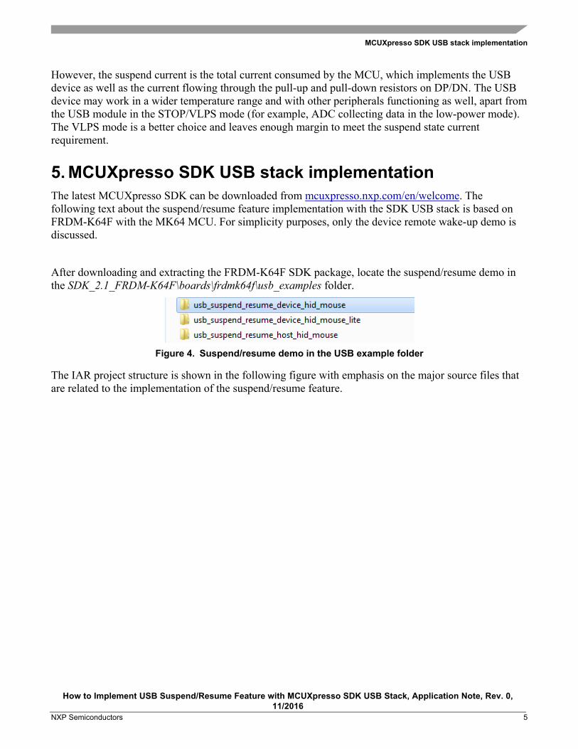
After downloading and extracting the FRDM-K64F SDK package, locate the suspend/resume demo in the SDK_2.1_FRDM-K64F\boards\frdmk64f\usb_examples folder.
Figure 4. Suspend/resume demo in the USB example folder
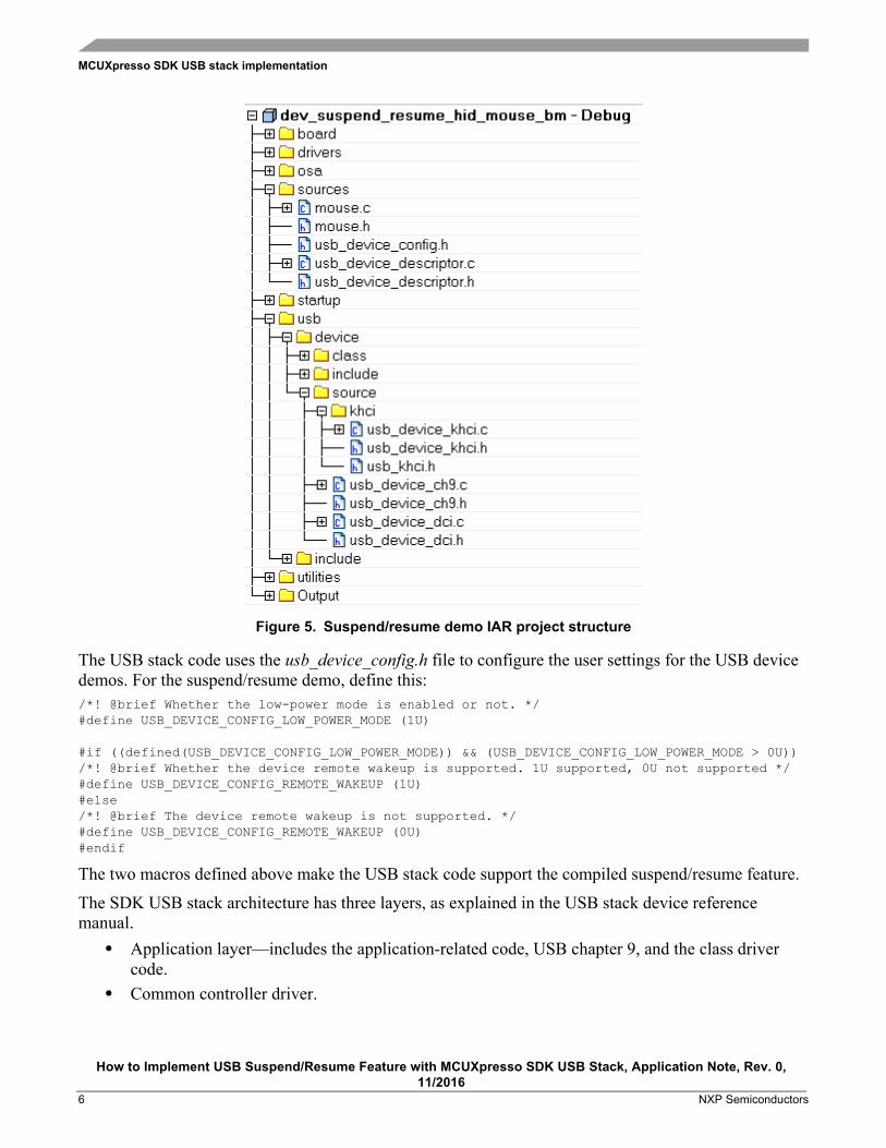
The IAR project structure is shown in the following figure with emphasis on the major source files that are related to the implementation of the suspend/resume feature.
MCUXpresso SDK USB stack implementation
How to Implement USB Suspend/Resume Feature with MCUXpresso SDK USB Stack, Application Note, Rev. 0, 11/2016
6 NXP Semiconductors
Figure 5. Suspend/resume demo IAR project structure
The USB stack code uses the usb_device_config.h file to configure the user settings for the USB device demos. For the suspend/resume demo, define this: /*! @brief Whether the low-power mode is enabled or not. */ #define USB_DEVICE_CONFIG_LOW_POWER_MODE (1U) #if ((defined(USB_DEVICE_CONFIG_LOW_POWER_MODE)) && (USB_DEVICE_CONFIG_LOW_POWER_MODE > 0U)) /*! @brief Whether the device remote wakeup is supported. 1U supported, 0U not supported */ #define USB_DEVICE_CONFIG_REMOTE_WAKEUP (1U) #else /*! @brief The device remote wakeup is not supported. */ #define USB_DEVICE_CONFIG_REMOTE_WAKEUP (0U) #endif
The two macros defined above make the USB stack code support the compiled suspend/resume feature.
The SDK USB stack architecture has three layers, as explained in the USB stack device reference manual.
• Application layer—includes the application-related code, USB chapter 9, and the class driver code.
• Common controller driver.

MCUXpresso SDK USB stack implementation
How to Implement USB Suspend/Resume Feature with MCUXpresso SDK USB Stack, Application Note, Rev. 0, 11/2016
NXP Semiconductors 7
• Device-specific USB controller driver—for the Kinetis FS USB controller, called the KHCI driver.
The following sections explain the majority of code required in each layer to support the suspend/resume and remote wakeup features.
5.1. Application layer The code to implement a HID mouse with the remote wakeup feature is in the mouse.c file. The main flow for handling the idle, suspend, and resume state change is handled by USB_DeviceSuspendResumeTask() with a state machine shown in this figure:
Figure 6. SuspendResumeTask state machine
The two events for the suspend and resume (kUSB_DeviceEventSuspend and kUSB_DeviceEventResume) are handled in USB_DeviceCallback(). The event code-passing route in the USB stack is as follows:
KHCI USB controller ISR -> Device controller (DCI) code -> Device Callback
For example, when the USB controller finds out that the USB bus entered the suspend state, it sets the SLEEP flag in the Kinetis USB controller and triggers the USB interrupt. In the USB ISR code, it sends out the suspend event code to the device callback defined within the application-layer code.
To support the remote wakeup feature, the USB chapter 9 standard requests Set Feature and Clear Feature are updated as follows. USB_DeviceSetStatus() is called to maintain the remote wakeup flag and send out the kUSB_DeviceEventSetRemoteWakeup event code to the device callback. static usb_status_t USB_DeviceCh9SetClearFeature(…) …
MCU wakeup with GPIO
MouseIdle
MouseSuspending
MouseSuspended
USB_PowerPreSwitchHook Entry into VLPS mode
USB_PowerPostSwitchHook
MouseStartResume Send the resume
signal if the remote wakeup is enabled
MouseResumed
kUSB_DeviceEventSuspend
kUSB_DeviceEventResume
Print out message to enable the user press switch to wake up the
MCU
Rotate mouse on PC
MCUXpresso SDK USB stack implementation
How to Implement USB Suspend/Resume Feature with MCUXpresso SDK USB Stack, Application Note, Rev. 0, 11/2016
8 NXP Semiconductors
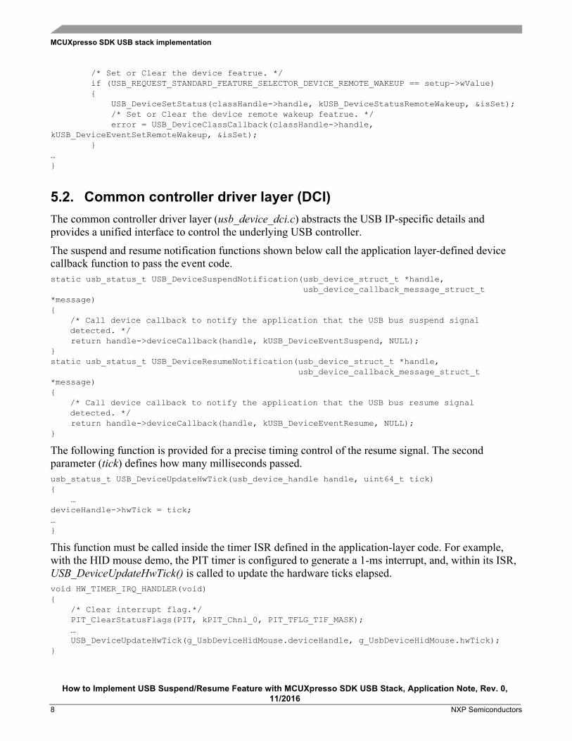
/* Set or Clear the device featrue. */ if (USB_REQUEST_STANDARD_FEATURE_SELECTOR_DEVICE_REMOTE_WAKEUP == setup->wValue) USB_DeviceSetStatus(classHandle->handle, kUSB_DeviceStatusRemoteWakeup, &isSet); /* Set or Clear the device remote wakeup featrue. */ error = USB_DeviceClassCallback(classHandle->handle, kUSB_DeviceEventSetRemoteWakeup, &isSet); …
5.2. Common controller driver layer (DCI) The common controller driver layer (usb_device_dci.c) abstracts the USB IP-specific details and provides a unified interface to control the underlying USB controller.
The suspend and resume notification functions shown below call the application layer-defined device callback function to pass the event code. static usb_status_t USB_DeviceSuspendNotification(usb_device_struct_t *handle, usb_device_callback_message_struct_t *message)
/* Call device callback to notify the application that the USB bus suspend signal detected. */
return handle->deviceCallback(handle, kUSB_DeviceEventSuspend, NULL); static usb_status_t USB_DeviceResumeNotification(usb_device_struct_t *handle, usb_device_callback_message_struct_t *message)
/* Call device callback to notify the application that the USB bus resume signal detected. */
return handle->deviceCallback(handle, kUSB_DeviceEventResume, NULL);
The following function is provided for a precise timing control of the resume signal. The second parameter (tick) defines how many milliseconds passed. usb_status_t USB_DeviceUpdateHwTick(usb_device_handle handle, uint64_t tick) … deviceHandle->hwTick = tick; …
This function must be called inside the timer ISR defined in the application-layer code. For example, with the HID mouse demo, the PIT timer is configured to generate a 1-ms interrupt, and, within its ISR, USB_DeviceUpdateHwTick() is called to update the hardware ticks elapsed. void HW_TIMER_IRQ_HANDLER(void) /* Clear interrupt flag.*/ PIT_ClearStatusFlags(PIT, kPIT_Chnl_0, PIT_TFLG_TIF_MASK); … USB_DeviceUpdateHwTick(g_UsbDeviceHidMouse.deviceHandle, g_UsbDeviceHidMouse.hwTick);
MCUXpresso SDK USB stack implementation
How to Implement USB Suspend/Resume Feature with MCUXpresso SDK USB Stack, Application Note, Rev. 0, 11/2016
NXP Semiconductors 9
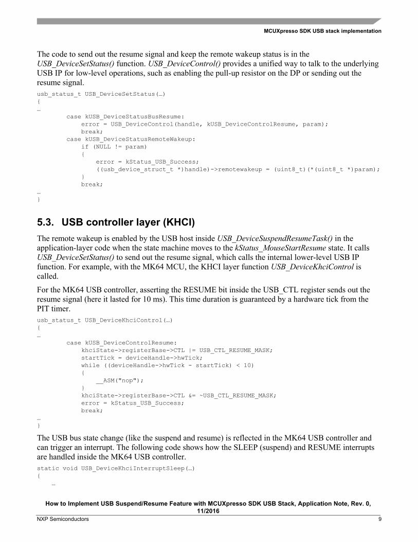
The code to send out the resume signal and keep the remote wakeup status is in the USB_DeviceSetStatus() function. USB_DeviceControl() provides a unified way to talk to the underlying USB IP for low-level operations, such as enabling the pull-up resistor on the DP or sending out the resume signal. usb_status_t USB_DeviceSetStatus(…) … case kUSB_DeviceStatusBusResume: error = USB_DeviceControl(handle, kUSB_DeviceControlResume, param); break; case kUSB_DeviceStatusRemoteWakeup: if (NULL != param) error = kStatus_USB_Success; ((usb_device_struct_t *)handle)->remotewakeup = (uint8_t)(*(uint8_t *)param); break; …
5.3. USB controller layer (KHCI) The remote wakeup is enabled by the USB host inside USB_DeviceSuspendResumeTask() in the application-layer code when the state machine moves to the kStatus_MouseStartResume state. It calls USB_DeviceSetStatus() to send out the resume signal, which calls the internal lower-level USB IP function. For example, with the MK64 MCU, the KHCI layer function USB_DeviceKhciControl is called.
For the MK64 USB controller, asserting the RESUME bit inside the USB_CTL register sends out the resume signal (here it lasted for 10 ms). This time duration is guaranteed by a hardware tick from the PIT timer. usb_status_t USB_DeviceKhciControl(…) … case kUSB_DeviceControlResume: khciState->registerBase->CTL |= USB_CTL_RESUME_MASK; startTick = deviceHandle->hwTick; while ((deviceHandle->hwTick - startTick) < 10) __ASM("nop"); khciState->registerBase->CTL &= ~USB_CTL_RESUME_MASK; error = kStatus_USB_Success; break; …
The USB bus state change (like the suspend and resume) is reflected in the MK64 USB controller and can trigger an interrupt. The following code shows how the SLEEP (suspend) and RESUME interrupts are handled inside the MK64 USB controller. static void USB_DeviceKhciInterruptSleep(…) …
Running the demo
How to Implement USB Suspend/Resume Feature with MCUXpresso SDK USB Stack, Application Note, Rev. 0, 11/2016
10 NXP Semiconductors
/* Enable the resume interrupt */ khciState->registerBase->INTEN |= kUSB_KhciInterruptResume; khciState->registerBase->USBTRC0 |= USB_USBTRC0_USBRESMEN_MASK; khciState->registerBase->USBCTRL |= USB_USBCTRL_SUSP_MASK; /* Disable the suspend interrupt */ khciState->registerBase->INTEN &= ~((uint32_t)kUSB_KhciInterruptSleep); … static void USB_DeviceKhciInterruptResume(…) … khciState->registerBase->USBCTRL &= ~USB_USBCTRL_SUSP_MASK; /* Enable the suspend interrupt */ khciState->registerBase->INTEN |= kUSB_KhciInterruptSleep; /* Disable the resume interrupt */ khciState->registerBase->INTEN &= ~((uint32_t)kUSB_KhciInterruptResume); khciState->registerBase->USBTRC0 &= ~USB_USBTRC0_USBRESMEN_MASK; …
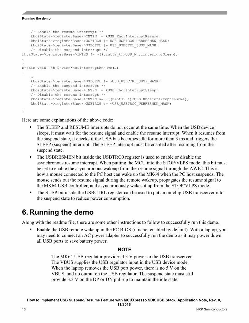
Here are some explanations of the above code: • The SLEEP and RESUME interrupts do not occur at the same time. When the USB device
sleeps, it must wait for the resume signal and enable the resume interrupt. When it resumes from the suspend state, it checks if the USB bus becomes idle for more than 3 ms and triggers the SLEEP (suspend) interrupt. The SLEEP interrupt must be enabled after resuming from the suspend state.
• The USBRESMEN bit inside the USBTRC0 register is used to enable or disable the asynchronous resume interrupt. When putting the MCU into the STOP/VLPS mode, this bit must be set to enable the asynchronous wakeup from the resume signal through the AWIC. This is how a mouse connected to the PC host can wake up the MK64 when the PC host suspends. The mouse sends out the resume signal during the remote wakeup, propagates the resume signal to the MK64 USB controller, and asynchronously wakes it up from the STOP/VLPS mode.
• The SUSP bit inside the USBCTRL register can be used to put an on-chip USB transceiver into the suspend state to reduce power consumption.
6. Running the demo Along with the readme file, there are some other instructions to follow to successfully run this demo.
• Enable the USB remote wakeup in the PC BIOS (it is not enabled by default). With a laptop, you may need to connect an AC power adapter to successfully run the demo as it may power down all USB ports to save battery power.
NOTE The MK64 USB regulator provides 3.3 V power to the USB transceiver. The VBUS supplies the USB regulator input in the USB device mode. When the laptop removes the USB port power, there is no 5 V on the VBUS, and no output on the USB regulator. The suspend state must still provide 3.3 V on the DP or DN pull-up to maintain the idle state.
Running the demo
How to Implement USB Suspend/Resume Feature with MCUXpresso SDK USB Stack, Application Note, Rev. 0, 11/2016
NXP Semiconductors 11
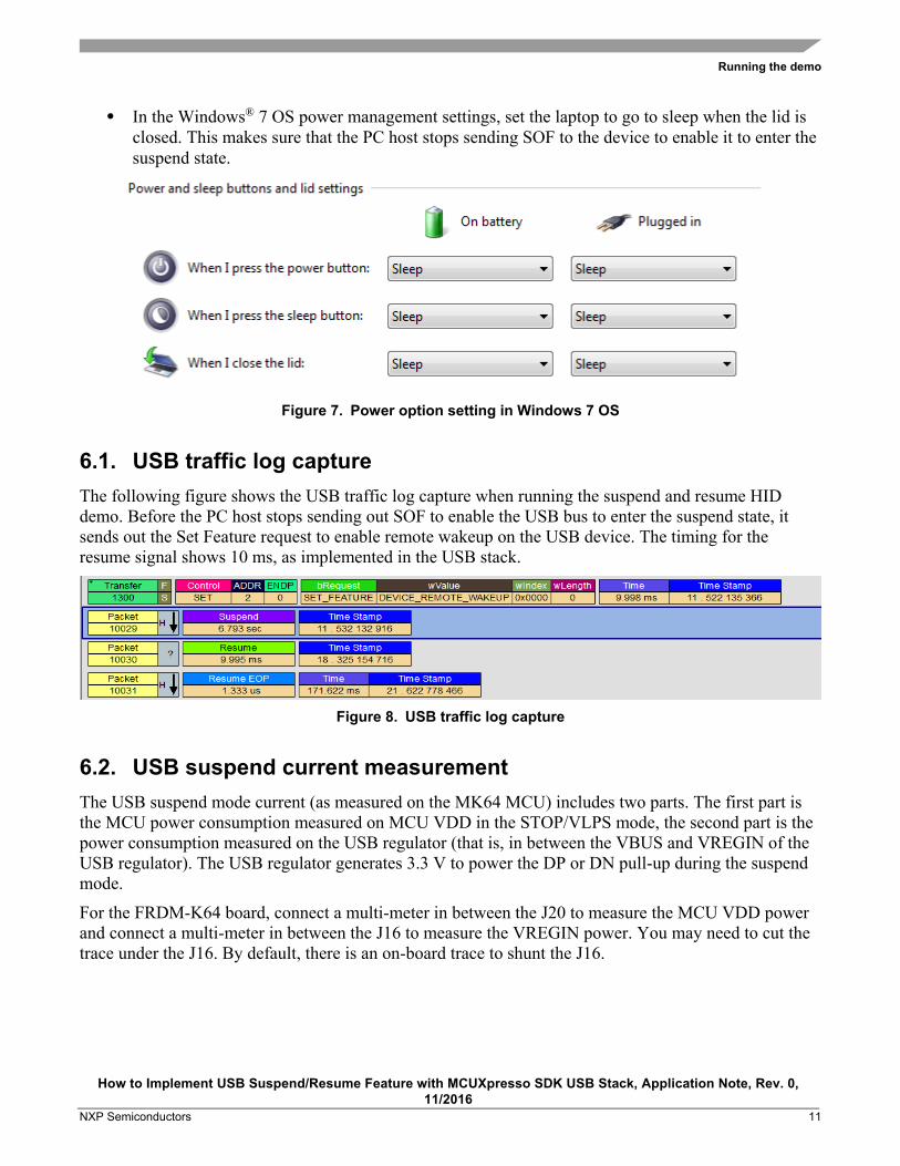
• In the Windows® 7 OS power management settings, set the laptop to go to sleep when the lid is closed. This makes sure that the PC host stops sending SOF to the device to enable it to enter the suspend state.
Figure 7. Power option setting in Windows 7 OS
6.1. USB traffic log capture The following figure shows the USB traffic log capture when running the suspend and resume HID demo. Before the PC host stops sending out SOF to enable the USB bus to enter the suspend state, it sends out the Set Feature request to enable remote wakeup on the USB device. The timing for the resume signal shows 10 ms, as implemented in the USB stack.
Figure 8. USB traffic log capture
6.2. USB suspend current measurement The USB suspend mode current (as measured on the MK64 MCU) includes two parts. The first part is the MCU power consumption measured on MCU VDD in the STOP/VLPS mode, the second part is the power consumption measured on the USB regulator (that is, in between the VBUS and VREGIN of the USB regulator). The USB regulator generates 3.3 V to power the DP or DN pull-up during the suspend mode.
For the FRDM-K64 board, connect a multi-meter in between the J20 to measure the MCU VDD power and connect a multi-meter in between the J16 to measure the VREGIN power. You may need to cut the trace under the J16. By default, there is an on-board trace to shunt the J16.
Running the demo
How to Implement USB Suspend/Resume Feature with MCUXpresso SDK USB Stack, Application Note, Rev. 0, 11/2016
12 NXP Semiconductors
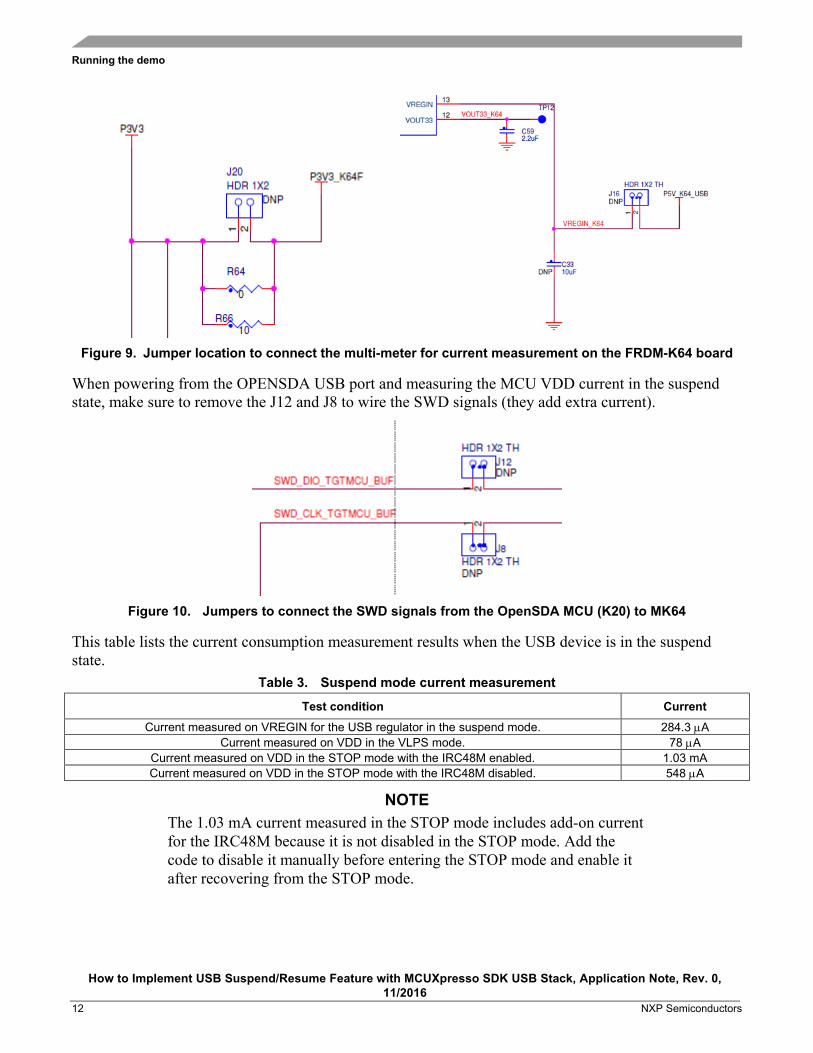
Figure 9. Jumper location to connect the multi-meter for current measurement on the FRDM-K64 board
When powering from the OPENSDA USB port and measuring the MCU VDD current in the suspend state, make sure to remove the J12 and J8 to wire the SWD signals (they add extra current).
Figure 10. Jumpers to connect the SWD signals from the OpenSDA MCU (K20) to MK64
This table lists the current consumption measurement results when the USB device is in the suspend state.
Table 3. Suspend mode current measurement
Test condition Current Current measured on VREGIN for the USB regulator in the suspend mode. 284.3 µA
Current measured on VDD in the VLPS mode. 78 µA Current measured on VDD in the STOP mode with the IRC48M enabled. 1.03 mA Current measured on VDD in the STOP mode with the IRC48M disabled. 548 µA
NOTE The 1.03 mA current measured in the STOP mode includes add-on current for the IRC48M because it is not disabled in the STOP mode. Add the code to disable it manually before entering the STOP mode and enable it after recovering from the STOP mode.
Revision history
How to Implement USB Suspend/Resume Feature with MCUXpresso SDK USB Stack, Application Note, Rev. 0, 11/2016
NXP Semiconductors 13
7. References • K64 Sub-Family Reference Manual (document K64P144M120SF5RM) • Kinetis K64F Sub-Family Data Sheet (document K64P144M120SF5) • USB2.0 Specification
8. Revision history Table 4. Revision history
Revision number Date Substantive changes 0 11/2016 Initial release
Document Number: AN5385 Rev. 0
11/2016
How to Reach Us:
Home Page: nxp.com
Web Support: nxp.com/support
Information in this document is provided solely to enable system and software implementers to use NXP products. There are no express or implied copyright licenses granted hereunder to design or fabricate any integrated circuits based on the information in this document. NXP reserves the right to make changes without further notice to any products herein.
NXP makes no warranty, representation, or guarantee regarding the suitability of its products for any particular purpose, nor does NXP assume any liability arising out of the application or use of any product or circuit, and specifically disclaims any and all liability, including without limitation consequential or incidental damages. “Typical” parameters that may be provided in NXP data sheets and/or specifications can and do vary in different applications, and actual performance may vary over time. All operating parameters, including “typicals,” must be validated for each customer application by customer’s technical experts. NXP does not convey any license under its patent rights nor the rights of others. NXP sells products pursuant to standard terms and conditions of sale, which can be found at the following address: nxp.com/SalesTermsandConditions.
NXP, the NXP logo, NXP SECURE CONNECTIONS FOR A SMARTER WORLD, Freescale, the Freescale logo, and Kinetis are trademarks of NXP B.V. All other product or service names are the property of their respective owners.
ARM, the ARM logo, and Cortex are registered trademarks of ARM Limited (or its subsidiaries) in the EU and/or elsewhere. All rights reserved. Windows is a registered trademark of Microsoft Corporation in the United States and/or other countries.
© 2016 NXP B.V.