how to find hidden cameras
TRANSCRIPT
How to find hidden cameras
Marc [email protected]
March 25, 2002
“We shall meet in the place where there is no darkness”– 1984, George Orwell
Abstract
While it was easy to spot cameras twenty years ago due to their large size, thishas become increasingly difficult during the last decade. Cameras have becomemuch smaller and consume a fraction of the power they did ten years ago. Due tothis, covert installation in nearly any imaginable place is possible. This paper willshow methods frequently used for hiding cameras as well as methods to detect andlocate covertly installed cameras.
Document available athttp://www.franken.de/users/tentacle/papers/
1 Introduction
During the last few years the number of surveillance cameras has grown out of bounds.Cameras have been installed in many public and semi-public places such as universities[1], streets, supermarkets, gas stations, parking garages, cinemas, bars, shops, busses,train stations and even discos.
About 25 million CCTV1 cameras are estimated to be in operation worldwide atthe time of writing [2]. Some countries, notably Great Britain, are trying to fully coverevery corner of public life with cameras. The Privacy International CCTV page [3]states that between 225 and 450 Million Dollars are spent on surveillance technologyin Britain per year, involving an estimated 300.000 cameras. These efforts result in aperson driving through the city of London being filmed at least once every five minutes[4]. In the near future cameras may even be installed in all taxis, keeping an eye onthe passengers [5]. In Houston, Texas, about 400 cabs have been equipped with suchcameras [6].
1Closed Circuit Television
1
It may not be obvious right away why it could be of any importance to anyone tobe able to locate hidden cameras. Some will reason that concealed cameras are more orless exotic and thus knowledge on how to find them is not necessary at all. Others evenconsider interest in how to locate hidden cameras to border the criminal. Both partieserr, as shall be illustrated in the following.
Contrary to common belief, hidden cameras are nowhere close to exotic. In 1996David Fletcher, chief executive of the British Security Industry Association, estimatedthat employers were spending 12 million british pounds a year on covert camera equip-ment to monitor their staff [7, p.49]. A survey conducted by the American Manage-ment Association found that “33 percent of major U.S. firms say they tape employees– overtly or covertly – to counter theft, violence, or sabotage” [8]. There have beenseveral reports of staff being monitored in changing rooms without their consent [9].Subminiature cameras were even discovered by the author of this paper during treat-ment at an oral surgeon’s practice: the camera was plastered into the ceiling next to aceiling light.
Subminiature camera modules are available for as cheap as $ 25 and even ready touse wireless subminiature cameras can be legally bought. Ease of use and the drop-ping prices highly contributed to the popularity of subminiature cameras. In effecthighly miniaturized cameras can be bought, installed and operated even by the aver-age citizen lacking financial resources and technical expertise. Due to this it is notuncommon for subminiature cameras to turn up in places that are in fact neither publicnor semi-public. There is a growing number of reports of covert cameras spying onunsuspecting persons in showers, bedrooms and changing rooms [11]. Knowing howto find covert cameras makes the voyeur’s job harder. Often even legally installed andoperated CCTV cameras are abused to peep on women for voyeuristic purposes. Ananalysis showed that 15 percent of all targeted CCTV surveillances on women initiatedby the camera operator were for “apparently voyeuristic reasons” [7, p.129].
While there is concern that persons interested in finding hidden cameras may havecriminal intentions, there are legitimate reasons for such interest as well. One importantreason can be concern about privacy and personal freedom. Especially the growing useof face recogniton software [12, 13, 14, 15, 16] is being strongly criticized [17]. Thereis no way to distinguish cameras that are connected to face recognition systems fromthose that are not. This is why persons who consider face recognition to touch theirpersonal freedom may choose to avoid surveillance cameras altogether. For instance,they may decide to avoid stores that excessively use video cameras and visit stores thatdo use significantly less or even none at all. This is not possible unless the presenceof cameras is detected in the first place. In countries with lenient privacy protectionlaws video sequences captured by CCTV cameras may even be legally shown on TV[18], no matter how humilating this may be for the affected persons (for an examplesee [19]).
Some people might argue that cameras are easy to find and this paper is thereforeunnecessary. Be assured that searching for covert cameras is in no way trivial. A mod-ern camera including transmitter and batteries will easily fit inside a box of cigarettes.The Institute of Microtechnology of the University of Neuchatel (Switzerland) is de-
2
signing CMOS based subminiature cameras small enough to fit inside a pen [20]. TheUS company Given® Imaging has even developed an “Ingestible Imaging Capsule”for medical applications that is small enough to be swallowed. The capsule contains acolor camera, batteries and a transmitter [21]. Given the size of those cameras it shouldbe clear by now why naive attempts to find cameras will not yield reliable results.
2 Types of cameras and lenses
The focus of this paper will be on electronic cameras. Subminiature photographic cam-eras exist as well, but those are not as popular as electronic cameras. This is becauseelectronic cameras are more flexible to install and operate. They facilitate real timeanalysis and can be installed in places that are not easily accessible, since there is noneed for changing films. On the other hand photographic cameras provide images farsuperior in quality to those of standard subminiature video cameras.
Ancient electronic cameras used camera tubes [22, 23] to convert the virtual imageof the filmed object to an electronic signal. There are several tube designs [24] whichall suffer from drawbacks such as high power consumption, sensitivity to mechanicalstress, large size, short lifetime of the picture tube or high lag. Although there are stillmany tube based surveillance cameras in operation, they are of low importance con-cerning covert surveillance. Therefore this paper will focus on modern semiconductorbased cameras.
The camera does not need to be in the same room as the object under surveillance.It is possible to connect the primary lens to the camera by means of fibre optics [25],which are very similar to those used for medical applications. One advantage of thisapproach is that very little space is needed where the lens is to be installed. Anotheradvantage is that detection of the lens can be made more difficult by using lens assem-blies made of non conductive materials. Lenses prepared this way can not be detectedwith metal detectors. Still another advantage is that otherwise inaccessible rooms canbe surveilled by feeding the fibre cable through sewage or air condition ducts.
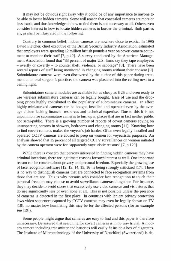
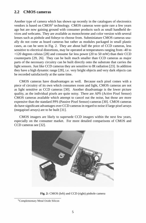
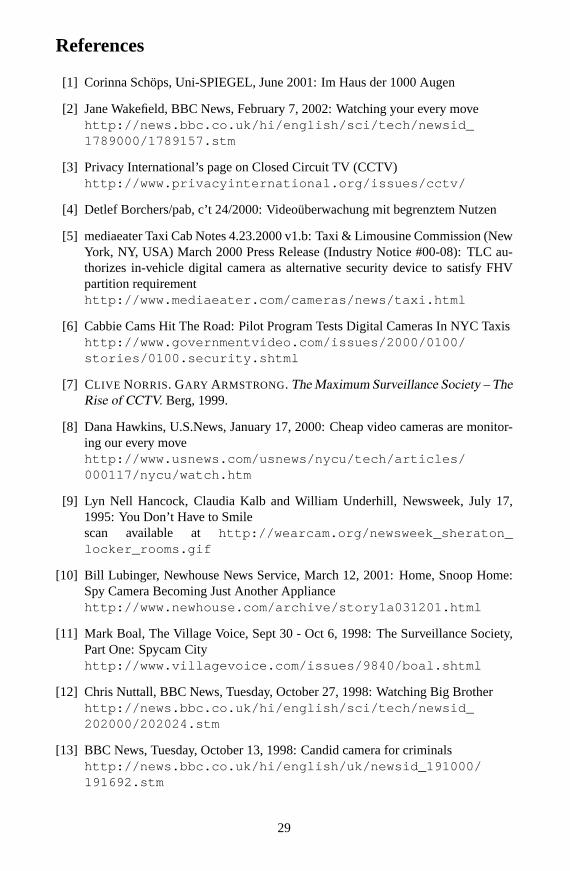
Fig. 1 shows some ways to obscure the camera’s lens. Lenses obscured as nail,screw, or rivet head can be seen. Alternatively the lens may be masked as a shirt button(not shown).
Fig. 1: Obscuring the camera’s lens (Picture courtesy of www.alarm.de)
3
2.1 CCD cameras
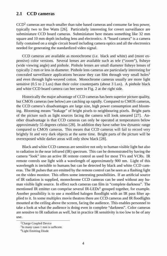
CCD2 cameras are much smaller than tube based cameras and consume far less power,typically two to five Watts [26]. Particularly interesting for covert surveillance aresubminiature CCD board cameras. Subminiature here means something like 32 mmsquare and 10 mm depth including lens and electronics. A ”board camera” is a camerafully contained on a single circuit board including camera optics and all the electronicsneeded for generating the standardized video signal.
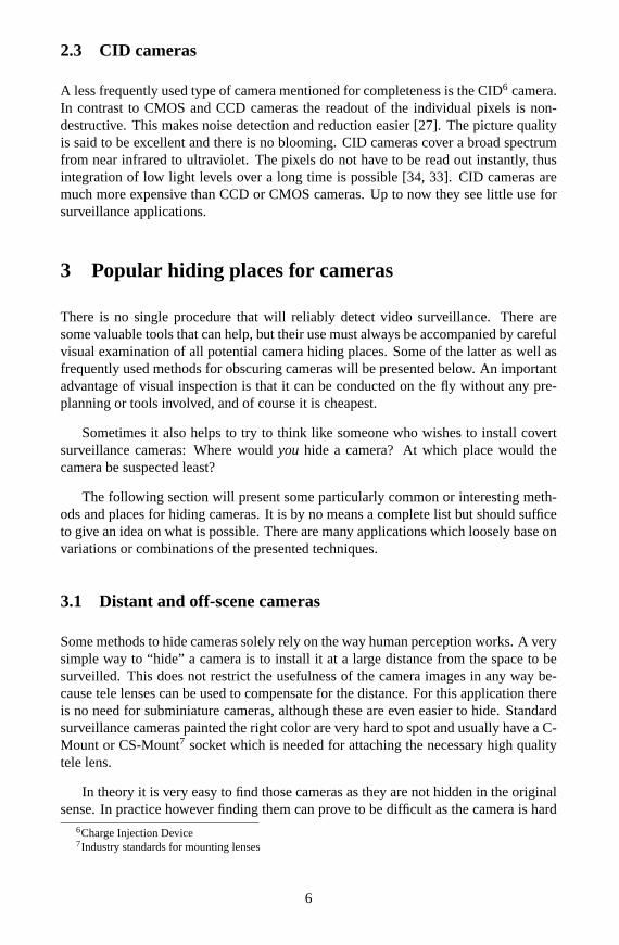
CCD cameras are available as monochrome (i.e. black and white) and (more ex-pensive) color versions. Several lenses are available such as tele (“zoom”), fisheye(wide viewing angle) and pinhole. Pinhole lenses are small diameter fisheye lenses oftypically 2 mm or less in diameter. Pinhole lens cameras are particularly interesting forconcealed surveillance applications because they can film through very small holes3
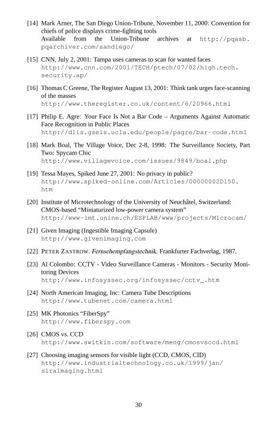
and even through light-weaved cotton. Monochrome cameras usually are more lightsensitive (0.5 to 2 Lux) than their color counterparts (about 3 Lux). A pinhole blackand white CCD board camera can bee seen in Fig. 2 at the right side.
Historically the major advantage of CCD cameras has been superior picture quality,but CMOS cameras (see below) are catching up rapidly. Compared to CMOS cameras,the CCD camera’s disadvantages are large size, high power consumption and bloom-ing. Blooming means “leakage” of bright pixels to neighbouring pixels. Bright partsof the picture such as light sources facing the camera will look smeared [27]. An-other disadvantage is that CCD cameras can only be operated at temperatures belowapproximately 55 degrees celsius [28]. In addition they have rather low dynamic rangecompared to CMOS cameras. This means that CCD cameras will fail to record verybrightly lit and very dark objects at the same time. Bright parts of the picture will beoverexposed while darker areas will only show black [28].
Black and white CCD cameras are sensitive not only to human visible light but alsoto radiation in the near infrared (IR) spectrum. This can be demonstrated by having thecamera “look” into an active IR remote control as used for most TVs and VCRs. IRremote conrols use light with a wavelength of approximately 900 nm. Light of thiswavelength is invisible to humans but can be detected by black and white CCD cam-eras. The IR pulses that are emitted by the remote control can be seen as a flashing lighton the video monitor. This offers some interesting possibilities. If an artificial sourceof IR radiation is supplied, monochrome CCD cameras can be used without any hu-man visible light source. In effect such cameras can film in “complete darkness”. Thementioned IR emitter can comprise several IR-LEDs4 grouped together, for example.Another possibility is to use a modified halogen floodlight with an IR pass filter ap-plied to it. In some multiplex movie theatres there are CCD cameras and IR floodlightsmounted at the ceiling above the screen, facing the audience. This enables personnel totake a look at what the audience is doing even in complete “darkness”. Color camerasare sensitve to IR radiation as well, but in practice IR sensitivity is too low to be of anyuse.
2Charge Coupled Device3In many cases 1 mm is sufficent.4Light Emitting Diode
4
2.2 CMOS cameras
Another type of camera which has shown up recently in the catalogues of electronicsvendors is based on CMOS5 technology. CMOS cameras were quite rare a few yearsago but are now gaining ground with consumer products such as small handheld de-vices and webcams. They are available as monochrome and color version with severallenses such as pinhole and fisheye to choose from. Subminiature CMOS cameras usu-ally do not come as board cameras but rather as modules packaged in small plasticcases, as can be seen in Fig. 2. They are about half the price of CCD cameras, lesssensitive to electrical distortions, may be operated at temperatures ranging from -40 to+120 degrees celsius [28] and consume far less power (20 to 50 mW) than their CCDcounterparts [29, 26]. They can be built much smaller than CCD cameras as majorparts of the necessary circuitry can be built directly onto the substrate that carries thelight sensors. Just like CCD cameras they are sensitive to IR radiation [23]. In additionthey have a high dynamic range [28], i.e. very bright objects and very dark objects canbe recorded satisfactorily at the same time.
CMOS cameras have disadvantages as well. Because each pixel comes with apiece of circuitry of its own which consumes room and light, CMOS cameras are notas light sensitive as CCD cameras [30]. Another disadvantage is the lower picturequality, as the individual pixels are quite noisy. There are APS (Active Pixel Sensor)CMOS cameras available which attempt to cancel out the noise, but those are moreexpensive than the standard PPS (Passive Pixel Sensor) cameras [30]. CMOS camerasdo have significant advantages over CCD cameras in regard to noise if large pixel arrays(megapixel arrays) are to be built [31].
CMOS imagers are likely to supersede CCD imagers within the next few years,especially on the consumer market. For more detailed comparisons of CMOS andCCD cameras see [32].
Fig. 2: CMOS (left) and CCD (right) pinhole camera
5Complementary Metal Oxide Silicon
5
2.3 CID cameras
A less frequently used type of camera mentioned for completeness is the CID6 camera.In contrast to CMOS and CCD cameras the readout of the individual pixels is non-destructive. This makes noise detection and reduction easier [27]. The picture qualityis said to be excellent and there is no blooming. CID cameras cover a broad spectrumfrom near infrared to ultraviolet. The pixels do not have to be read out instantly, thusintegration of low light levels over a long time is possible [34, 33]. CID cameras aremuch more expensive than CCD or CMOS cameras. Up to now they see little use forsurveillance applications.
3 Popular hiding places for cameras
There is no single procedure that will reliably detect video surveillance. There aresome valuable tools that can help, but their use must always be accompanied by carefulvisual examination of all potential camera hiding places. Some of the latter as well asfrequently used methods for obscuring cameras will be presented below. An importantadvantage of visual inspection is that it can be conducted on the fly without any pre-planning or tools involved, and of course it is cheapest.
Sometimes it also helps to try to think like someone who wishes to install covertsurveillance cameras: Where wouldyou hide a camera? At which place would thecamera be suspected least?
The following section will present some particularly common or interesting meth-ods and places for hiding cameras. It is by no means a complete list but should sufficeto give an idea on what is possible. There are many applications which loosely base onvariations or combinations of the presented techniques.
3.1 Distant and off-scene cameras
Some methods to hide cameras solely rely on the way human perception works. A verysimple way to “hide” a camera is to install it at a large distance from the space to besurveilled. This does not restrict the usefulness of the camera images in any way be-cause tele lenses can be used to compensate for the distance. For this application thereis no need for subminiature cameras, although these are even easier to hide. Standardsurveillance cameras painted the right color are very hard to spot and usually have a C-Mount or CS-Mount7 socket which is needed for attaching the necessary high qualitytele lens.
In theory it is very easy to find those cameras as they are not hidden in the originalsense. In practice however finding them can prove to be difficult as the camera is hard
6Charge Injection Device7Industry standards for mounting lenses
6
to spot within the large surrounding scenery. This is why there has been disagreementon whether such cameras are to be considered hidden (e.g. [36]). Examples includecameras installed on roofs, church bell towers or trees. Model planes (such as the“MLB Bat” [35]) that are equipped with miniature cameras and transmitters fall in thesame category.
Another scheme that is based on how human perception works exploits the fact thatcameras usually are expected to be installed at face level or above. Examples for thisare cameras installed at service counters below waistline or even at floor level. In mostcases those cameras are noticed only by persons that suspect a hidden camera.
3.2 Two-way mirrors
One of the most widely known places for hiding cameras is behind two-way mirrors.Those are frequently seen on TV shows such as “Hidden Camera”. Other names fortwo-way mirrors are “one-way mirrors”, “partially silvered mirrors” and “half-silveredmirrors”.
Two-way mirrors differ from standard mirrors in two aspects. First they lack theintransparent coating which is applied to the back side of standard mirrors [37]. Sec-ond the reflective coating (silver or aluminium [38, 39]) is less dense than that of usualmirrors. The density of the reflective layer can be chosen as desired during manufac-turing. The more dense the layer, the more light is reflected and the less light is passedthrough the mirror.
Because not all of the light that hits the mirror is reflected, two-way mirrors appearto be darker than usual mirrors. However this should not be relied upon when lookingfor two-way mirrors. Because the density of the reflective coating can be chosen freelythere is no definite value to distinguish two-way mirrors from regular ones. If theattacker wants to make sure the mirror is not suspected to be a two-way mirror he willchoose more dense coatings. This will result in a visible loss of picture quality, ofcourse.
Tests with normal mirrors8 showed that standard black and white CCD board cam-eras can film through those only in bright sunshine. Even then only very brighly litobjects can be seen.
In general two-way mirrors can be seen through in both directions. Sometimes itis possible to take a look through two-way mirrors “the wrong way” by shielding thesurrounding light from the mirror. Whether this works largely depends on the densityof the reflective coating and the light levels at the viewer’s side of the mirror.
In most cases mirrors are easily spotted once an eye is kept open for them. Due tothis it is not difficult to find cameras that are concealed behind mirrors. Of course thisassumes that the person looking for cameras is able to closely inspect and unmount themirrors. Unfortunately in many cases this is not possible, such as with wall mounted
8Optical mirrors without backside coating that were salvaged from an old document scanner
7
mirrors on public ground.
Real life examples of mirrors used to obscure cameras include cameras concealedwithin the rear view mirrors of cars [40] and cameras hidden behind bathroom mirrors[41].
3.3 Ceiling and surroundings
Another place where cameras can be hidden is on top of suspended ceilings. After asmall hole is drilled through one of the ceiling tiles a subminiature pinhole camera canbe hidden on top of it. Usually there is enough room on top to mount even standardcamcorders. In many cases there is no need for drilling any holes because most ceilingtiles have holes of differing sizes for acoustic and design reasons. If the camera isinstalled next to a light source it is even more difficult to spot. There have already beennumerous reports of hidden cameras that were installed on top of suspended ceilings[8].
Cameras may also film through the gratings of ventilation shafts. Alternativelyminiature cameras can be hidden inside ceiling mounted smoke detectors9. In factmany surveillance technology companys offer prepared smoke detectors [43]. As SteveMann pointed out [42] the bad thing about those is that tampering with fire equipment(including smoke detectors) is against the law. This means that smoke detectors thatare suspected to contain cameras maynot be dismounted, disassembled or obstructed.
According to a US patent, cameras even may be disguised as fire sprinkler heads[44]. A cylindrical assembly containing mirrors and lenses is mounted within the sprin-kler head and the camera itself is mounted on top of the ceiling. This device gives aview of almost 360 degrees round the sprinkler head. Another quite elaborate methodis to hide the camera within a prepared floodlight bulb [45, 46].
3.4 Dome cameras
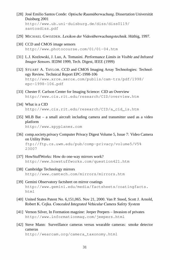
This type of camera can often be seen at train stations and other public places. A domecamera basically comprises a camera mounted within a semi transparent dome. Usuallythose domes are suspended from or mounted to the ceiling (see Fig. 3). On a casualglance they are easily mistaken as light sources. They often blend in unobtrusively withtheir environment which is why some consider them to be hidden cameras.
The dome and its interior is painted black, this makes it more difficult to discoverthe camera installed inside. The camera films through a transparent spot in the blackcover of the dome. Some cameras are fixed within the dome while others can be re-motely rotated and panned. So-called “speed domes” achieve rotation speeds of up to400 degrees per second [29]. Some vendors even claim 600 degrees per second [47].
9This was shown quite nicely in the film “Enemy of the State®”
8
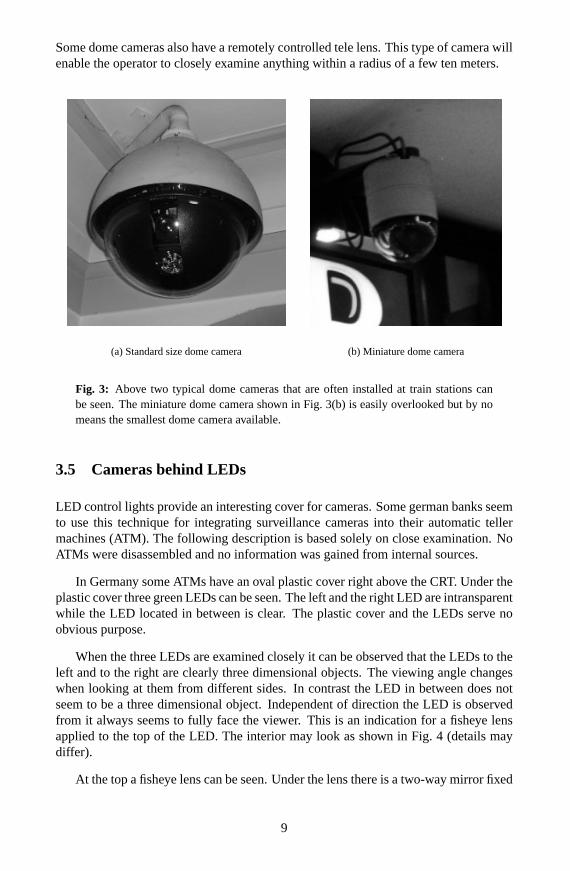
Some dome cameras also have a remotely controlled tele lens. This type of camera willenable the operator to closely examine anything within a radius of a few ten meters.
(a) Standard size dome camera (b) Miniature dome camera
Fig. 3: Above two typical dome cameras that are often installed at train stations canbe seen. The miniature dome camera shown in Fig. 3(b) is easily overlooked but by nomeans the smallest dome camera available.
3.5 Cameras behind LEDs
LED control lights provide an interesting cover for cameras. Some german banks seemto use this technique for integrating surveillance cameras into their automatic tellermachines (ATM). The following description is based solely on close examination. NoATMs were disassembled and no information was gained from internal sources.
In Germany some ATMs have an oval plastic cover right above the CRT. Under theplastic cover three green LEDs can be seen. The left and the right LED are intransparentwhile the LED located in between is clear. The plastic cover and the LEDs serve noobvious purpose.
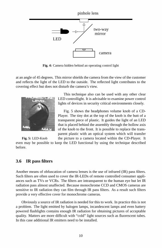
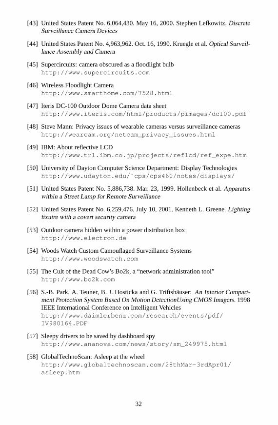
When the three LEDs are examined closely it can be observed that the LEDs to theleft and to the right are clearly three dimensional objects. The viewing angle changeswhen looking at them from different sides. In contrast the LED in between does notseem to be a three dimensional object. Independent of direction the LED is observedfrom it always seems to fully face the viewer. This is an indication for a fisheye lensapplied to the top of the LED. The interior may look as shown in Fig. 4 (details maydiffer).
At the top a fisheye lens can be seen. Under the lens there is a two-way mirror fixed
9
pinhole lens
mirror
camera
LED
two-way
Fig. 4: Camera hidden behind an operating control light
at an angle of 45 degrees. This mirror shields the camera from the view of the customerand reflects the light of the LED to the outside. The reflected light contributes to thecovering effect but does not disturb the camera’s view.
This technique also can be used with any other clear
Fig. 5: LED-Knob
LED controllight. It is advisable to examine power controllights of devices in security critical environments closely.
Fig. 5 shows the headphones volume knob of a CD-Player. The tiny dot at the top of the knob is the butt of atransparent piece of plastic. It guides the light of an LEDthat is placed behind the assembly through the hollow axisof the knob to the front. It is possible to replace the trans-parent plastic with an optical system which will transferthe picture to a camera located within the CD-Player. It
even may be possible to keep the LED functional by using the technique describedbefore.
3.6 IR pass filters
Another means of obfuscation of camera lenses is the use of infrared (IR) pass filters.Such filters are often used to cover the IR-LEDs of remote controlled consumer appli-ances such as TVs or VCRs. The filters are intransparent to the human eye but let IRradiation pass almost unaffected. Because monochrome CCD and CMOS cameras aresensitive to IR radiation they can film through IR pass filters. As a result such filtersprovide a very effective cover for monochrome cameras.
Obviously a source of IR radiation is needed for this to work. In practice this is nota problem. The light emitted by halogen lamps, incandescent lamps and even batterypowered flashlights contains enough IR radiation for obtaining pictures of acceptablequality. Matters are more difficult with “cold” light sources such as fluorescent tubes.In this case additional IR emitters need to be installed.
10
Experiments showed that many semi transparent display covers of CD-Players andVCRs show characteristics very similar to those of IR pass filters. Most display coverslet IR radiation pass almost unaffected but prevent the user from examining the internalstructure of the display. Cameras installed behind the display covers of householdapplicances are very difficult to spot.
IR pass filters can also be integrated into wall plates [43]. Similar installationsthat contain IR pass filters (“black glass” [48]) can often be seen in public restrooms.They house motion sensors that activate water taps, automatic flushing mechanisms orhand driers. Of course nothing prevents anyone from using them as a discrete cover forsubminiature cameras.
3.7 Liquid Crystal Displays
Many battery powered digital alarm clocks contain reflective LC Displays (twistednematic type) [49, 50]. Those LC displays make an almost perfect cover for pinholecameras.
The following experiment was made with a cheap digital table clock which had anLC display measuring about 5 cm by 3 cm.
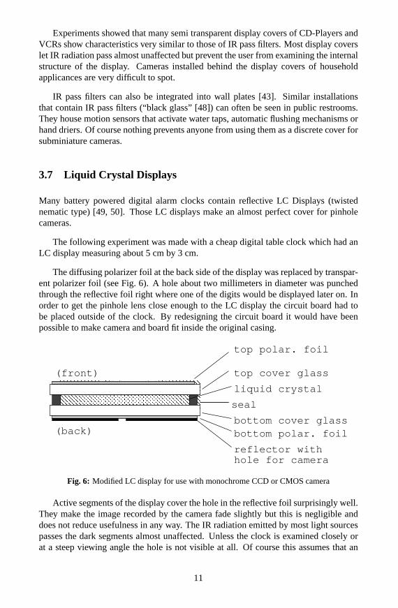
The diffusing polarizer foil at the back side of the display was replaced by transpar-ent polarizer foil (see Fig. 6). A hole about two millimeters in diameter was punchedthrough the reflective foil right where one of the digits would be displayed later on. Inorder to get the pinhole lens close enough to the LC display the circuit board had tobe placed outside of the clock. By redesigning the circuit board it would have beenpossible to make camera and board fit inside the original casing.
top polar. foil
top cover glass
liquid crystal
seal
(front)
(back)bottom cover glassbottom polar. foil
reflector withhole for camera
Fig. 6: Modified LC display for use with monochrome CCD or CMOS camera
Active segments of the display cover the hole in the reflective foil surprisingly well.They make the image recorded by the camera fade slightly but this is negligible anddoes not reduce usefulness in any way. The IR radiation emitted by most light sourcespasses the dark segments almost unaffected. Unless the clock is examined closely orat a steep viewing angle the hole is not visible at all. Of course this assumes that an
11
active segment is displayed on top of the hole all the time. This prerequisite can be metby placing the hole beneath one of the dots of the column that separates hours fromminutes, for example.
3.8 Outdoor surveillance
Some ways of hiding surveillance cameras outdoors have already been mentioned insection 3.1. Several more will be presented in this section.
There is a US patent that describes how to integrate surveillance cameras into streetlamps [51]. The authors of the patent suggest to replace the photo detector on top ofthe lamp with a small tube that contains a small periscope. In combination with servosthis will offer a 360 degree view. The camera can be remotely controlled by means ofDTMF audio signals transmitted to the unit via phone lines or other communicationchannels. As an alternative the camera may be installed inside the lamp housing. Inthis case it would look downwards through the protective glass cover. The authorsfurther suggest to replace the standard bulb usually used for street lamps with a halogenquartz tube. This may be necessary to free some room for the camera. Because theemitted spectrum of halogen quartz tubes radically differs from that of the standardstreet lamps10 color filters must be used, otherwise modified street lamps would bevery easy to distinguish from unmodified ones. Another US patent describes how tointegrate covert cameras into outdoor lighting fixtures [52].
Among the outdoor installations that can house surveillance cameras are powerdistribution boxes [53] and power transformers (“pole pigs”). The pole mounted trans-formers are often seen in the United States and sometimes in Europe as well. Forsurveillance applications usually dummy transformers are installed which contain onlythe camera and the necessary communication circuitry. The viewing window of thecamera is claimed to be noticeable by taking a close look [51] but of course this shouldnot be relied upon.
Hidden cameras may even be installed in the woods. “Woods Watch” has developedseveral camouflaged surveillance systems for outdoor use. Cameras hidden within treestumps, bird houses and rocks are available [54]. The cameras are Hi-8 camcorderswith nightshot function and can be activated by passive infrared (PIR) motion detectorsand seismic sensors.
3.9 Taking over pre-installed cameras
Another possibility which is rarely thought of is the “takeover” of cameras owned orinstalled by the victim. This includes cameras that are integrated by default into devicesowned by the victim. If the attacker succeeds in gaining control over those cameras,the victim can be spied upon unnoticed.
10Usually fluorescent light tubes, sodium vapor lamps or mercury vapor lamps are used.
12
Though the victim is well aware of the camera she does not consider that it mightbe used for purposes other than intended by her. In effect cameras that have been takenover are very similar to hidden cameras. Taking over victim owned cameras exploits acommon misconception, namely the confusion of the idea of ownership with the ideaof control. Owning a device neither makes that device trusted nor does it automaticallygrant full control over the device.
A good example for cameras that can be taken over are computer controlled minia-ture cameras, commonly called “webcams”. Those have become very popular recentlyand are available for prices as low as $ 45. Control over the computer the camera isattached to results in control over the camera itself. Given the fact that trojan basedtakeovers are trivial with many popular home user operating systems, this is a seriousrisk. Some trojans even support grabbing images from attached webcams by default[55]. This clearly shows that computer securitydoesmatter – in many cases a breakinwill not only affect the machine itself but also its environment. It is strongly suggestednot to attach any microphones or cameras to networked computers permanently. Thisapplys just as well to toys such as the Lego® Mindstorms™11 ”Vision Command” setwhich is essentially a small webcam with added functionality.
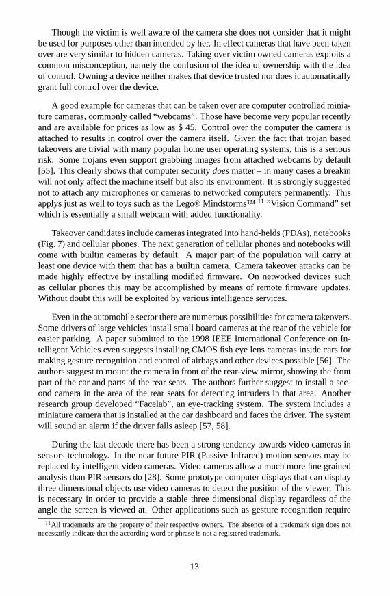
Takeover candidates include cameras integrated into hand-helds (PDAs), notebooks(Fig. 7) and cellular phones. The next generation of cellular phones and notebooks willcome with builtin cameras by default. A major part of the population will carry atleast one device with them that has a builtin camera. Camera takeover attacks can bemade highly effective by installing modified firmware. On networked devices suchas cellular phones this may be accomplished by means of remote firmware updates.Without doubt this will be exploited by various intelligence services.
Even in the automobile sector there are numerous possibilities for camera takeovers.Some drivers of large vehicles install small board cameras at the rear of the vehicle foreasier parking. A paper submitted to the 1998 IEEE International Conference on In-telligent Vehicles even suggests installing CMOS fish eye lens cameras inside cars formaking gesture recognition and control of airbags and other devices possible [56]. Theauthors suggest to mount the camera in front of the rear-view mirror, showing the frontpart of the car and parts of the rear seats. The authors further suggest to install a sec-ond camera in the area of the rear seats for detecting intruders in that area. Anotherresearch group developed “Facelab”, an eye-tracking system. The system includes aminiature camera that is installed at the car dashboard and faces the driver. The systemwill sound an alarm if the driver falls asleep [57, 58].
During the last decade there has been a strong tendency towards video cameras insensors technology. In the near future PIR (Passive Infrared) motion sensors may bereplaced by intelligent video cameras. Video cameras allow a much more fine grainedanalysis than PIR sensors do [28]. Some prototype computer displays that can displaythree dimensional objects use video cameras to detect the position of the viewer. Thisis necessary in order to provide a stable three dimensional display regardless of theangle the screen is viewed at. Other applications such as gesture recognition require
11All trademarks are the property of their respective owners. The absence of a trademark sign does notnecessarily indicate that the according word or phrase is not a registered trademark.
13
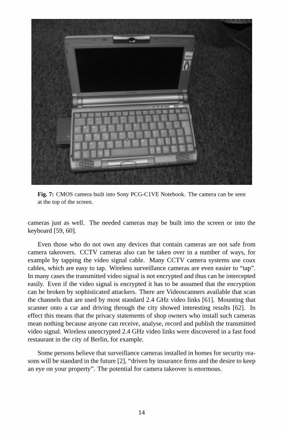
Fig. 7: CMOS camera built into Sony PCG-C1VE Notebook. The camera can be seenat the top of the screen.
cameras just as well. The needed cameras may be built into the screen or into thekeyboard [59, 60].
Even those who do not own any devices that contain cameras are not safe fromcamera takeovers. CCTV cameras also can be taken over in a number of ways, forexample by tapping the video signal cable. Many CCTV camera systems use coaxcables, which are easy to tap. Wireless surveillance cameras are even easier to “tap”.In many cases the transmitted video signal is not encrypted and thus can be interceptedeasily. Even if the video signal is encrypted it has to be assumed that the encryptioncan be broken by sophisticated attackers. There are Videoscanners available that scanthe channels that are used by most standard 2.4 GHz video links [61]. Mounting thatscanner onto a car and driving through the city showed interesting results [62]. Ineffect this means that the privacy statements of shop owners who install such camerasmean nothing because anyone can receive, analyse, record and publish the transmittedvideo signal. Wireless unencrypted 2.4 GHz video links were discovered in a fast foodrestaurant in the city of Berlin, for example.
Some persons believe that surveillance cameras installed in homes for security rea-sons will be standard in the future [2], “driven by insurance firms and the desire to keepan eye on your property”. The potential for camera takeover is enormous.
14
3.10 Other hiding places
The list of possible hiding places for cameras can be continued forever. Among thecommercially available prepared devices that contain cameras are flower pots, silkplants, bird houses, dolls or stuffed animals [63] (camera may be in the foot [11]), man-nequin dolls (camera inside the eye [64]), briefcases, books, folders, pencil sharpeners,pens [67], tissue boxes, shirts, ties, bottles, vitamine bottles, fish tanks, air purifiers andeyeglasses [69].
Among the electronic devices that can contain cameras are portable radios (camerabehind the tuning scale), wall clocks, table clocks, radio clocks, wrist watches [65],lamps, coffee machines, emergency lights, exit signs, speakers, VCRs [66], motiondetectors [68] and thermostat clocks.
Another interesting method for obscuring the lens is the use of a fake radio antenna.The optics are concealed within the base of the antenna. The light is reflected to thecamera by means of several mirrors, similar to a periscope [70]. One of the secrets thesuspected russian spy Robert Hanssen is claimed to have exposed is the installation ofminiature cameras in the headlights of vehicles of known Russian spies [71]. Similarinstallations also are suggested by a US patent on “vehicular safety systems” [40].
Often cameras are hidden behind paintings [72] or posters. Prepared paintings andpictures sometimes can be found in the catalogues of electronics mail order supplies.
Cameras be can hidden inside wall mounted light switches quite easily. Many lightswitches can be modified to contain subminiature CCD or CMOS cameras. Some lightswitches have small integrated control lights. The covers of those control lights can beused to conceal the camera’s lens. Satisfying results can also be achieved by replacingthe cover of the control light with an IR pass filter.
A special application of hidden cameras are body worn cameras. Those may behidden within a baseball cap and film through holes in the cap. Other possibilitiesinclude hiding the camera beneath a shirt or jacket or inside knapsacks or similar bodyworn items. The lens may be obscured by means of any of the techniques presented insection 2.
4 Electronic aids for finding cameras
Up to this point places for hiding cameras were mentioned as well as techniques whichaid in doing so. The information that has been presented so far can give some ideason what is possible and what to search for. It is a good basis for visual inspection. Inmost cases, however, visual inspection is not sufficent and must be backed by means ofone or several of the techniques presented below. It is advisable to use several of thesetechniques because this makes detection more reliable in regard to both false positiveand false negative alerts. Not all devices and techniques that are mentioned below areeasily adopted for home use.
15
4.1 Metal detector
Though metal detectors originally were not intended to be used as counterespionagetools they can be of use to the counterespionage specialist. Most surveillance devices,including cameras, contain conductive parts that can be detected with a metal detector.
The main problem with metal detectors is that they will detect any conductive ob-ject. Because there are a lot of conductive objects in most environments a lot of falsealerts will be experienced. This makes reliable detection of surveillance devices verydifficult. Depending on the type of metal detector that is used (BFO, pulse or VLF) it ispossible to discriminate several metals, but this is of low use in this case. Despite this,metal detectors an still be useful if they are used in combinaton with other tools. In ad-dition they work quite fine for scanning wooden objects such as as desks or cupboardsthat do not contain any conductors.
Construction plans for simple metal detectors that employ the beat frequency prin-ciple (BFO) can be found on the web [73, 74].
4.2 Non-Linear Junction Detector
A device more suited to the application of counterespionage is the so called “Non-Linear Junction Detector” (NLJD). Most electronic surveillance devices contain non-linear components, such as transistors or tunnel diodes. In contrast to metal detectors,NLJDs will only detect non-linear components. Regular conductive objects will nottrigger an alert.
The NLJD emits a clean signal in the 900 MHz area and the reflections of thissignal are analysed for harmonics. Non-linear components will cause characteristicharmonics to appear within the reflected signal. Those harmonics are not observed insignals reflected by linear components. Non-linear objects can be located at distancesof up to a few inches by slowly sweeping suspect areas [75]. NLJDs can even detectunpowered or defective surveillance devices.
They have certain disadvantages as well. Some junctions of different metals shownon-linear behavior and thus will result in false alerts. In practice those junctions canbe distinguished from electronic parts because they cause a slightly different harmonicpattern. Another method to distinguish the two is to apply mechanical stress to theobject under examination. This can be done by hitting it with a rubber hammer, for ex-ample. Metallic junctions will change their electronic characteristics and thus modulatethe reflected signal, resulting in audible cracks on the receiver. In contrast electronicparts usually keep their characteristics upon mechanical stress and thus will remainsilent [76]. It is not known whether it is possible to trick NLJDs by installing certainmetallic junctions next to the electronic parts that should be hidden.
An attacker may fool NLJDs by appropriately shielding his surveillance devices.This is possible because NLJDs employ frequencies in the 900 MHz range that canbe shielded quite easily [75]. Of course the shield itself is likely to be detected when
16
scanning for conductive parts, but under some circumstances this technique may beuseful to the attacker nevertheless.
It has also been suggested that additional circuitry may be installed that “listens”for strong signals in the frequency bands used by most NLJDs. This circuitry then maydestroy itself and the device by means of a high voltage pulse in order to escape detec-tion by the NLJD [75]. It is quite obvious that this may be exploited by the surveillancevictim as well, such as by sweeping all objects with a cheap signal generator. 900 MHzcell phones may cause surprising results just as well.
For obvious reasons NLJDs can not be used to detect cameras hidden within otherelectronic devices. The most important argument against the use of an NLJD probablyis its high price.
4.3 Time Domain Reflectometry
In section 3.9 (“camera takeover attempts”) it was suggested that it is possible to takeover preinstalled CCTV systems by tapping the cables that carry the video signal. Suchtaps can be detected by means of a Time Domain Reflectometer (TDR).
TDRs can be used to analyse the reflective properties of wires and cables. The basicprinciple is to feed pulses of short duration into the cable and view the reflection of thepulses by means of an attached oscilloscope. Splices, taps, short circuits and open endswill cause different behavior concerning reflections and thus can be distinguished fromeach other [77]. The time between the transmission of the pulse and the reception ofits reflection can be read from the oscilloscope screen. Knowledge of this time makesit possible to estimate the distance to the location where the reflection occurs.
Professional TDRs are expensive, but a simple TDR pulse generator can be homemade for about $20. In addition to the pulse generator a fast oscilloscope is needed,which can be quite expensive itself. Tomi Engdahl has published plans [78] for aTDR pulse generator based on a circuit idea published in Electronics Design magazineOctober 1, 1998. He includes some interesting links to additional information on theuse of TDRs.
One of the disadvantages of TDRs is that they can not detect capacitively isolateddevices and inductive taps [77]. Also after some experiments with the home made TDRit became clear that this kind of analysis does not work well with cables shorter thantwo or three meters. With short cables the reflection arrived within the so called blindspot [79] and was close to invisible within the rising edge of the pulse. Interpretationof the displayed curves is difficult and requires experience.
4.4 X-ray inspection systems
Counterespionage specialists use X-ray based inspection systems when they suspectthat covert surveillance devices were embedded into objects that can not be disassem-
17
bled easily. As an example, an X-ray scan may be done for detecting bugs that aredisguised as standard components (such as a capacitors). Other examples are furnitureor devices too costly or precious to disassemble them, such as objects of high personalvalue or antiques. Similar X-ray scanning system are used for the routine inspection ofluggage at airports.
X-ray based inspection systems can be divided into two groups: film based systemsand digital systems. Film based systems are the more traditional approach. They arewell known to the general public due to their use in the medical sector. With film basedsystems an X-ray emitter and a sheet of photographic film are placed at opposite sidesof the object that is to be examinated. After the film has been chemically processed thetypical black and white see-through image can be seen. Because of the high sensitivityof the film only a short pulse of X-rays of sufficent intensity is needed. Digital systemsdo not use photographic film but an electronic detector. The signals generated by thedetector are analysed by a computer which then displays the captured image. Thesystems that can be seen at airports usually are digital systems.
The major disadvantage of professional X-ray systems is their large size, highweight and high price. Readers who have the necessay budget may consider the site ofHeimann Systems [80] (a manufacturer of security related inspection equipment) to beof interest. Skilled readers who do not have the necessary budget might take interestin Jochen Kronjager’s High Voltage and X-ray page [81] which describes the construc-tion of a home made X-ray emitter. Please keep in mind that X-rays pose a major threatto health. It is probably not advisable to use home built devices for detecting hiddencameras. Emission of X-rays in public places is likely to result in legal action and mustbe considered irresponsible at least.
Most X-ray scanning systems have yet another disadvantage. Usually X-ray sensorand emitter need to be placed at opposite sides of the object under examination. This isnot a problem with small objects but will cause trouble if walls or large objects must beinspected. A possible solution to this is a technology developed by the Sandia NationalLaboratories (Albuquerque, USA) [82]. By carefully analysing the backscattered X-rays it is possible to picture the interior of solid objects. For this technique only one sideof the object under examination needs to be accessible. This technology was developedto aid in bomb detection but can be used for other applications just as well. The bodyscan systems that are used at some US airports use a similar technique [83].
4.5 Detecting video transmitters
In many cases the attacker is unable to install any video cables that conduct the videosignal from the camera to his video screen. There are other means of transmissionthat are far more suited to the attacker’s needs than plain video cables, which are timeconsuming to install. In this section techniques for transmitting video signals as wellas techniques to detect such transmissions will be presented.
18
4.5.1 RF transmission
The classic method to wirelessly transmit signals is to use modulated radio frequency(RF). RF video transmitters can be detected with special equipment such as spectrumanalysers. Spectrum analysers graphically display a frequency versus signal strengthgraph12. It is possible to tell from the displayed graph what frequencies a signal iscomposed of. Video signals have several well known typical characteristics. The stan-dard NTSC color video signal has a bandwidth of 6 MHz (though less than 600 kHzare possible [84]), a line frequency of about 16 kHz and a vertical sync frequency of60 Hz. Video modulated RF signals thus can be distinguished from other signals.
Analysis can be tricky if the signal is transferred digitally or if frequency hopping,burst transmission or an exotic modulation is used. Examples include the so calledspread spectrum technique which masks transmissions as random noise. In this casemore sophisticated devices such as Vector Signal Analysers [85] are needed, but this isfar beyond the scope of this paper.
In [86] a “video countermeasures device” is proposed that consists of a flashinglight bulb. The basic idea is to coerce the camera into generating a video signal ofknown characteristics. The RF signal emitted by the video transmitter can be identifiedby scanning the RF bands for signals that match those characteristics.
Standard video links that are available from most HiFi equipment dealers can bedetected very easily. Most transmitters operate in the 2.4 GHz band and use one of fivefreely usable channels. As already mentioned in section 3.9 scanners are available thatscan those channels for video signals [61]. Because this type of scanner only scans afixed set of frequencies it can not be used to reliably detect RF video transmissions.
4.5.2 Wire bound transmission
Wireless transmission is not the only way to transmit video signals without installingany additional cables [84]. The video signal can be transmitted by means of unusedpower wiring or telephone lines. Even though power wiring is by no means adaptedto the impedance of the video signal source it is possible to transmit the signal acrosssome distance. In an experimental setup the video signal was fed into an otherwiseunconnected extension cord of 15 meters in length. At the remote end of the extensionthe video signal still resulted in acceptable picture quality. Though quality can notbe expected to meet broadcast standards the signal still is perfectly usable. With asimple amplifier and differential transmission distances of up to 1500 meters can beachieved with twisted pair cable [90], up to 700 meters with telephone wiring [91].Baseband transmission can be difficult if no unused wire pair is available. In this casethe attacker may modulate a carrier with the video signal and feed this signal into thepower wiring. This technique is called carrier current transmission and is used by mostwire bound babyphones, for example. Both carrier current transmission and baseband
12This is can be accomplished with a computer doing Fast Fourier Transformation (FFT) or by means ofpurely analog circuitry.
19
transmission can be detected by analysing all conductors with signal analysis tools suchas oscilloscopes and spectrum analysers.
Conductors do not necessarily need to be wires. Keep an eye on anything con-ductive that is not implicitly grounded. Even drain pipes that contain water shouldbe measured. In an experimental setup video signals were successfully transmitted bymeans of an iron banister that extended across three floors, without using any additionalamplifiers.
4.5.3 Optical video links
As an alternative the video signal may be transmitted optically by means of an Infrared(IR) transmitter. This also works with visible light, but this is rarely done because suchvisible links are easily discovered. The emitter may use a IR semiconductor laser orseveral IR LEDs grouped together. Optical video links can not be detected by standardRF detection equipment except for the local emissions of the IR transmitter controlcircuitry.
Because IR radiation can not be detected by the human eye additional tools suchas IR sensitive CMOS or CCD cameras are required for detecting IR transmitters. Forsharply focused transmitters it can be necessary that the camera faces the transmitter,otherwise smoke must be used as a reflector to render the IR beam visible. Keep inmind that the attacker’s receiver needs to face the transmitter, too. Alternatively hemay guide the rays by means of mirrors or window panes, but visual contact mustalways be made somehow. Detailed analysis of any discovered IR radiation is possiblewith IR sensors coupled to signal analysis tools.
4.5.4 Communication networks
The video signal can also be transferred by means of communication networks. Exam-ples are analog and ISDN phone lines, mobile phone networks and computer networks.Data may be fed into those networks by taking over victim owned cameras that areattached to networked devices (see Section 3.9). Instead of taking control over a net-worked device that is owned by the victim the attacker may choose to install additionalminiature computers the victim is not aware of. Such miniature computers can be smallembedded special purpose systems. Examples are special webcam servers that includea tcp/ip stack and an ethernet interface. If IP traffic is considered too obvious, as analternative the video stream may be transmitted at the ethernet layer. Another exampleare video stream servers that can be attached to ISDN networks.
The obvious approach for detecting video signals transmitted on regular communi-cation networks is to monitor all networks. This will detect plain video transmissionsbut will fail to detect video data disguised as innocuous data. As an example, the at-tacker may make a workstation do a webcam snapshot. The captured image then couldbe sent one piece a time by replacing the Mail-IDs of all outgoing mail with chunks ofbase64 encoded picture data. If the attacker can sniff the outgoing traffic somehow he
20
will be able to combine the data into the complete snapshot. Such transmission paths,commonly known as “covert channels”, are difficult to prevent.
4.6 Detecting the camera’s emissions
Most cameras emit a typical spectrum of electromagnetic noise. The emissions mostlyresult from the pixel readout clock signal and components of the video signal. Theemitted spectrum is quite similar for any camera that generates a standard video signal.It is possible to locate electronic cameras by scanning for this spectrum. Depending onthe frequencies of the signal components proper shielding may foil detection attempts,but often cameras are not shielded at all.
4.6.1 Detecting the clock signal
Most CCD board cameras and CMOS module cameras use one out of a small set ofwell known standard clock frequencies. Table 1 lists some typical values. The OV5016single chip camera that is mentioned in the table is used in the camera that can be seenin Fig. 2 at the left. The CCD camera shown in Fig. 2 at the right uses the KS7214timing/sync generator that is listed in Table 1.
Sync Generator or Camera NTSC/EIA clock PAL/CCIR clock
CXD2463R, KS7214 19.06992 MHz 18.93750 MHz28.63636 MHz 28.37500 MHz
OV5116, OV5006 series, V-X0071 12.288 MHz 13.5 MHzOV7500 14.318181 MHz 17.73265 MHzVV5430 12.0000 MHz 14.7456 MHz
Table 1: Clock frequencies of some common camera and sync generator chips.CXD2463R and KS7214 are sync generator chips for CCD cameras, all others are singlechip CMOS cameras. See references [92] to [98] for further details.
In order to get an idea on what the emitted frequency spectrum looks like the emis-sions of a CMOS and a CCD camera were measured by means of a magnetic test loopconnected to a spectrum analyser. The tested cameras were the two cameras shown inFig. 2.
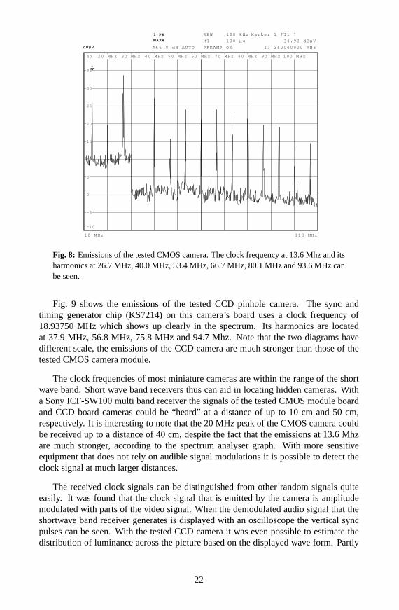
Fig. 8 shows the frequency spectrum emitted by the subminiature single chip CMOScamera that is based on the OV5016 chip [97]. According to the OV5016 datasheet [95]this camera uses a clock frequency of 13.5 MHz. The peak of the clock signal showsup very well in the spectrum. Most of the other peaks are harmonics of the clockfrequency. Those peaks are located at 26.7 Mhz, 40.0 MHz, 53.4 MHz, 66.7 MHz,80.1 MHz and 93.6 MHz. For this measurement the camera was set up exactly assuggested by its manual, including 78L05 voltage regulator and filter capaciators. Thesudden jump in sensitiviy at 30 MHz is due to an automatic change in bandwidth of thespectrum analyzer.
21
10 MHz 110 MHz
dBµVdBµV
1 PK
MAXH
RBW 120 kHz
MT 100 µs
PREAMP ONAtt 0 dB AUTO
20 MHz 30 MHz 40 MHz 50 MHz 60 MHz 70 MHz 80 MHz 90 MHz 100 MHz
-10
-5
0
5
10
15
20
25
30
35
40
1
Marker 1 [T1 ]
34.92 dBµV
13.360000000 MHz
Fig. 8: Emissions of the tested CMOS camera. The clock frequency at 13.6 Mhz and itsharmonics at 26.7 MHz, 40.0 MHz, 53.4 MHz, 66.7 MHz, 80.1 MHz and 93.6 MHz canbe seen.
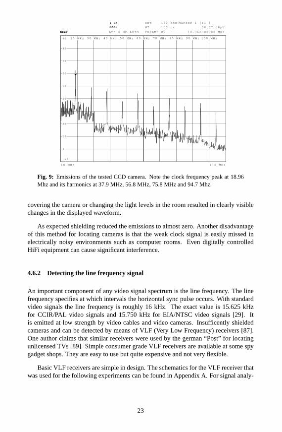
Fig. 9 shows the emissions of the tested CCD pinhole camera. The sync andtiming generator chip (KS7214) on this camera’s board uses a clock frequency of18.93750 MHz which shows up clearly in the spectrum. Its harmonics are locatedat 37.9 MHz, 56.8 MHz, 75.8 MHz and 94.7 Mhz. Note that the two diagrams havedifferent scale, the emissions of the CCD camera are much stronger than those of thetested CMOS camera module.
The clock frequencies of most miniature cameras are within the range of the shortwave band. Short wave band receivers thus can aid in locating hidden cameras. Witha Sony ICF-SW100 multi band receiver the signals of the tested CMOS module boardand CCD board cameras could be “heard” at a distance of up to 10 cm and 50 cm,respectively. It is interesting to note that the 20 MHz peak of the CMOS camera couldbe received up to a distance of 40 cm, despite the fact that the emissions at 13.6 Mhzare much stronger, according to the spectrum analyser graph. With more sensitiveequipment that does not rely on audible signal modulations it is possible to detect theclock signal at much larger distances.
The received clock signals can be distinguished from other random signals quiteeasily. It was found that the clock signal that is emitted by the camera is amplitudemodulated with parts of the video signal. When the demodulated audio signal that theshortwave band receiver generates is displayed with an oscilloscope the vertical syncpulses can be seen. With the tested CCD camera it was even possible to estimate thedistribution of luminance across the picture based on the displayed wave form. Partly
22
dBµVdBµV
1 PK
MAXH
Att 0 dB AUTO
10 MHz 110 MHz
RBW 120 kHz
MT 100 µs
PREAMP ON
20 MHz 30 MHz 40 MHz 50 MHz 60 MHz 70 MHz 80 MHz 90 MHz 100 MHz
-10
0
10
20
30
40
50
60
70
80
90
1
Marker 1 [T1 ]
58.37 dBµV
18.960000000 MHz
Fig. 9: Emissions of the tested CCD camera. Note the clock frequency peak at 18.96Mhz and its harmonics at 37.9 MHz, 56.8 MHz, 75.8 MHz and 94.7 Mhz.
covering the camera or changing the light levels in the room resulted in clearly visiblechanges in the displayed waveform.
As expected shielding reduced the emissions to almost zero. Another disadvantageof this method for locating cameras is that the weak clock signal is easily missed inelectrically noisy environments such as computer rooms. Even digitally controlledHiFi equipment can cause significant interference.
4.6.2 Detecting the line frequency signal
An important component of any video signal spectrum is the line frequency. The linefrequency specifies at which intervals the horizontal sync pulse occurs. With standardvideo signals the line frequency is roughly 16 kHz. The exact value is 15.625 kHzfor CCIR/PAL video signals and 15.750 kHz for EIA/NTSC video signals [29]. Itis emitted at low strength by video cables and video cameras. Insufficently shieldedcameras and can be detected by means of VLF (Very Low Frequency) receivers [87].One author claims that similar receivers were used by the german “Post” for locatingunlicensed TVs [89]. Simple consumer grade VLF receivers are available at some spygadget shops. They are easy to use but quite expensive and not very flexible.
Basic VLF receivers are simple in design. The schematics for the VLF receiver thatwas used for the following experiments can be found in Appendix A. For signal analy-
23
sis a 44 kHz PC soundcard13 and spectrum analyser software was used. Depending onthe distance between the camera and the VLF antenna a peak at the line frequency canbe observed on the displayed spectrum graph.
Several pickup coils were tried as antennas. Tests with a simple 2 cm coil showedpromising results. The distance at which cameras could be detected was increasedalmost by four times by using a resonant coil wound on a ferrite rod. Details on theconstruction of this coil can be found in Appendix B.
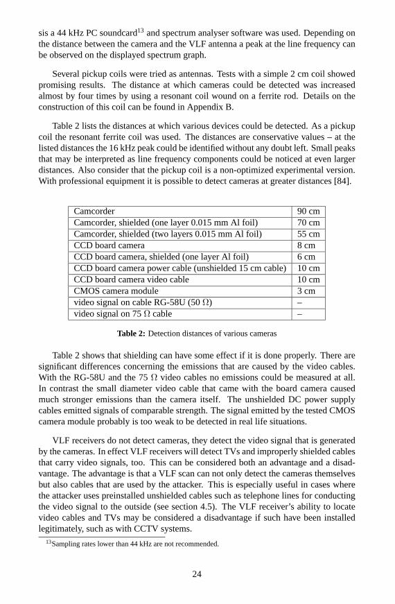
Table 2 lists the distances at which various devices could be detected. As a pickupcoil the resonant ferrite coil was used. The distances are conservative values – at thelisted distances the 16 kHz peak could be identified without any doubt left. Small peaksthat may be interpreted as line frequency components could be noticed at even largerdistances. Also consider that the pickup coil is a non-optimized experimental version.With professional equipment it is possible to detect cameras at greater distances [84].
Camcorder 90 cmCamcorder, shielded (one layer 0.015 mm Al foil) 70 cmCamcorder, shielded (two layers 0.015 mm Al foil) 55 cmCCD board camera 8 cmCCD board camera, shielded (one layer Al foil) 6 cmCCD board camera power cable (unshielded 15 cm cable)10 cmCCD board camera video cable 10 cmCMOS camera module 3 cmvideo signal on cable RG-58U (50Ω) –video signal on 75Ω cable –
Table 2: Detection distances of various cameras
Table 2 shows that shielding can have some effect if it is done properly. There aresignificant differences concerning the emissions that are caused by the video cables.With the RG-58U and the 75Ω video cables no emissions could be measured at all.In contrast the small diameter video cable that came with the board camera causedmuch stronger emissions than the camera itself. The unshielded DC power supplycables emitted signals of comparable strength. The signal emitted by the tested CMOScamera module probably is too weak to be detected in real life situations.
VLF receivers do not detect cameras, they detect the video signal that is generatedby the cameras. In effect VLF receivers will detect TVs and improperly shielded cablesthat carry video signals, too. This can be considered both an advantage and a disad-vantage. The advantage is that a VLF scan can not only detect the cameras themselvesbut also cables that are used by the attacker. This is especially useful in cases wherethe attacker uses preinstalled unshielded cables such as telephone lines for conductingthe video signal to the outside (see section 4.5). The VLF receiver’s ability to locatevideo cables and TVs may be considered a disadvantage if such have been installedlegitimately, such as with CCTV systems.
13Sampling rates lower than 44 kHz are not recommended.
24
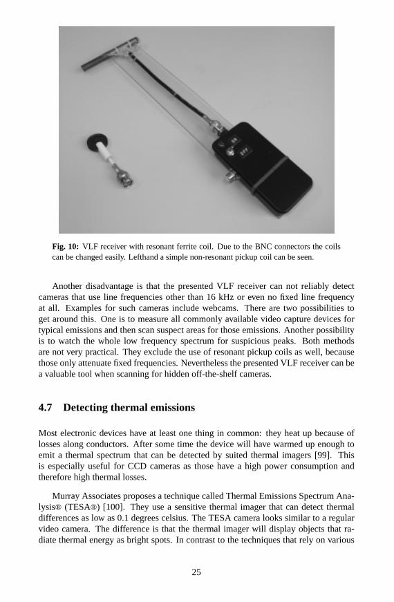
Fig. 10: VLF receiver with resonant ferrite coil. Due to the BNC connectors the coilscan be changed easily. Lefthand a simple non-resonant pickup coil can be seen.
Another disadvantage is that the presented VLF receiver can not reliably detectcameras that use line frequencies other than 16 kHz or even no fixed line frequencyat all. Examples for such cameras include webcams. There are two possibilities toget around this. One is to measure all commonly available video capture devices fortypical emissions and then scan suspect areas for those emissions. Another possibilityis to watch the whole low frequency spectrum for suspicious peaks. Both methodsare not very practical. They exclude the use of resonant pickup coils as well, becausethose only attenuate fixed frequencies. Nevertheless the presented VLF receiver can bea valuable tool when scanning for hidden off-the-shelf cameras.
4.7 Detecting thermal emissions
Most electronic devices have at least one thing in common: they heat up because oflosses along conductors. After some time the device will have warmed up enough toemit a thermal spectrum that can be detected by suited thermal imagers [99]. Thisis especially useful for CCD cameras as those have a high power consumption andtherefore high thermal losses.
Murray Associates proposes a technique called Thermal Emissions Spectrum Ana-lysis® (TESA®) [100]. They use a sensitive thermal imager that can detect thermaldifferences as low as 0.1 degrees celsius. The TESA camera looks similar to a regularvideo camera. The difference is that the thermal imager will display objects that ra-diate thermal energy as bright spots. In contrast to the techniques that rely on various
25
electronic emissions this technique is not easily fooled if the camera is switched offas soon as a bug sweep is suspected. This is because the camera and the surroundingmatter will keep its raised temperature long enough to be detected by TESA scans.
A major disadvantage of this technique is that cameras installed right next to orinside light sources will most likely not be detected within the “thermal blaze”. Itis unknown whether TESA will detect low power CMOS cameras. CMOS camerasgenerate only a fraction of the heat CCD cams do and thus may be more difficultto detect. Murray Associates claims that their TESA scan can even reveal activatedmicrophones by showing thermal differences, so CMOS cameras may show up as well.
4.8 Detection by means of a Laser
Science&Engineering Associates (SEA Inc.) has developed a product named “Spy-Finder™”. It employs two low power (below 5 mW/Laser Class III) lasers with a wave-length of about 635 nm (visible red spectrum) [101, 102, 87]. It works optically using“proprietary optics”. The camera is said to appear as a blinking red light in the viewingwindow. This is claimed to work against all kinds of cameras even when unpowered,within a distance of 5 to 50 feet. The device is further claimed to detect night visiondevices (at distances of up to more than 50 meters) and binoculars [87]. A consumergrade version of this device also is available [103].
The quoted texts do not make it clear how the device works. One text states that theconsumer grade version employs an “invisible detection beam”, and that the “camera’slens reflects back as a flashing dot in the SpyFinder’s viewer” [104]. Kevin D. Murrayfrom Murray Associates notes that neither the commercial version nor the consumergrade version can detect cameras that are hidden behind an IR filter [88]. Judging fromthe facts presented a vague guess is that the device detects reflective circular curvedobjects (which a lens usually is).
5 Conclusion
Several locations and techniques that are frequently used for hiding subminiature cam-eras were presented. In addition technical countermeasures were described. Thoughthis document does not make the reader a counterespionage specialist, it provides somebasic information which can be used to detect simple espionage attempts. Feedback oncameras that were detected by using the information presented within this paper iswelcome.
Keep in mind that the first step towards finding hidden cameras is suspicion. Con-trary to popular belief hidden cameras arenot rare. There is no easier target for awould-be voyeur than a non-suspecting person. Do not panic but be aware of the po-tential threat. Without doubt cameras will become still smaller during the next decadeand thus even more difficult to locate. The “Smart Dust” project of the University ofCalifornia, Berkeley might give an idea of what is yet to come [106].
26
Acknowledgement
I would like to thank the following persons for their reviews, comments, support andcontributions:
Basti, Matthias Brustle, Robert Dorn, Florian Gruner, Renato Romero, RolandSchulz and Prof. Dr.-Ing. M. Albach and Dr.-Ing. H. Rossmanith from University ofErlangen.
Appendix A Construction of a VLF receiver
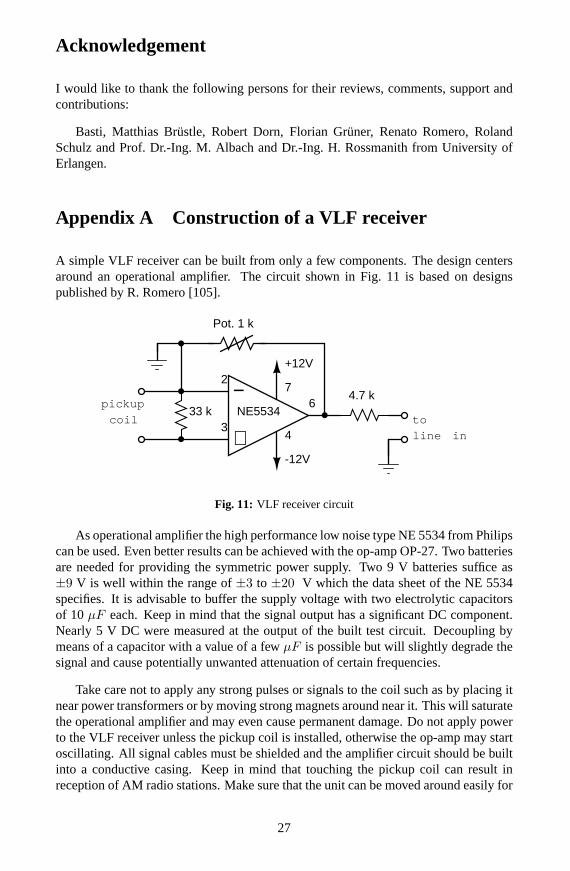
A simple VLF receiver can be built from only a few components. The design centersaround an operational amplifier. The circuit shown in Fig. 11 is based on designspublished by R. Romero [105].
NE5534
4
7
3
2
64.7 k
Pot. 1 k
33 k
−
+
+12V
-12V
pickup
coil
line in
to
Fig. 11: VLF receiver circuit
As operational amplifier the high performance low noise type NE 5534 from Philipscan be used. Even better results can be achieved with the op-amp OP-27. Two batteriesare needed for providing the symmetric power supply. Two 9 V batteries suffice as±9 V is well within the range of±3 to ±20 V which the data sheet of the NE 5534specifies. It is advisable to buffer the supply voltage with two electrolytic capacitorsof 10 µF each. Keep in mind that the signal output has a significant DC component.Nearly 5 V DC were measured at the output of the built test circuit. Decoupling bymeans of a capacitor with a value of a fewµF is possible but will slightly degrade thesignal and cause potentially unwanted attenuation of certain frequencies.
Take care not to apply any strong pulses or signals to the coil such as by placing itnear power transformers or by moving strong magnets around near it. This will saturatethe operational amplifier and may even cause permanent damage. Do not apply powerto the VLF receiver unless the pickup coil is installed, otherwise the op-amp may startoscillating. All signal cables must be shielded and the amplifier circuit should be builtinto a conductive casing. Keep in mind that touching the pickup coil can result inreception of AM radio stations. Make sure that the unit can be moved around easily for
27
scanning without the need to touch any part of the pickup coil.
The generated audio signal is roughly line-in level, i.e. it can be fed to line-inconnectors of HiFi components or soundcards of personal computers.
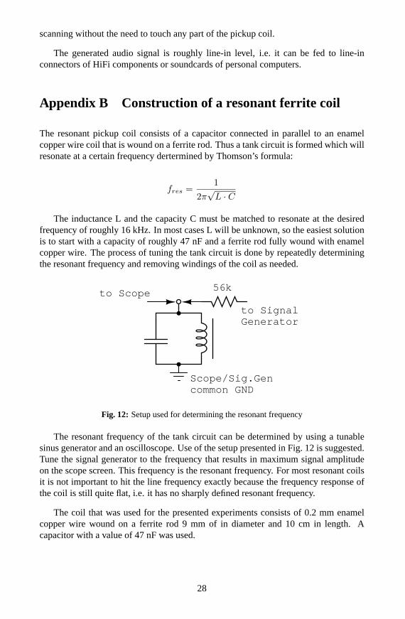
Appendix B Construction of a resonant ferrite coil
The resonant pickup coil consists of a capacitor connected in parallel to an enamelcopper wire coil that is wound on a ferrite rod. Thus a tank circuit is formed which willresonate at a certain frequency dertermined by Thomson’s formula:
fres =1
2π√L · C
The inductance L and the capacity C must be matched to resonate at the desiredfrequency of roughly 16 kHz. In most cases L will be unknown, so the easiest solutionis to start with a capacity of roughly 47 nF and a ferrite rod fully wound with enamelcopper wire. The process of tuning the tank circuit is done by repeatedly determiningthe resonant frequency and removing windings of the coil as needed.
to Scope
to SignalGenerator
56k
Scope/Sig.Gencommon GND
Fig. 12: Setup used for determining the resonant frequency
The resonant frequency of the tank circuit can be determined by using a tunablesinus generator and an oscilloscope. Use of the setup presented in Fig. 12 is suggested.Tune the signal generator to the frequency that results in maximum signal amplitudeon the scope screen. This frequency is the resonant frequency. For most resonant coilsit is not important to hit the line frequency exactly because the frequency response ofthe coil is still quite flat, i.e. it has no sharply defined resonant frequency.
The coil that was used for the presented experiments consists of 0.2 mm enamelcopper wire wound on a ferrite rod 9 mm of in diameter and 10 cm in length. Acapacitor with a value of 47 nF was used.
28
References
[1] Corinna Schops, Uni-SPIEGEL, June 2001: Im Haus der 1000 Augen
[2] Jane Wakefield, BBC News, February 7, 2002: Watching your every movehttp://news.bbc.co.uk/hi/english/sci/tech/newsid_1789000/1789157.stm
[3] Privacy International’s page on Closed Circuit TV (CCTV)http://www.privacyinternational.org/issues/cctv/
[4] Detlef Borchers/pab, c’t 24/2000: Videouberwachung mit begrenztem Nutzen
[5] mediaeater Taxi Cab Notes 4.23.2000 v1.b: Taxi & Limousine Commission (NewYork, NY, USA) March 2000 Press Release (Industry Notice #00-08): TLC au-thorizes in-vehicle digital camera as alternative security device to satisfy FHVpartition requirementhttp://www.mediaeater.com/cameras/news/taxi.html
[6] Cabbie Cams Hit The Road: Pilot Program Tests Digital Cameras In NYC Taxishttp://www.governmentvideo.com/issues/2000/0100/stories/0100.security.shtml
[7] CLIVE NORRIS. GARY ARMSTRONG. The Maximum Surveillance Society – TheRise of CCTV. Berg, 1999.
[8] Dana Hawkins, U.S.News, January 17, 2000: Cheap video cameras are monitor-ing our every movehttp://www.usnews.com/usnews/nycu/tech/articles/000117/nycu/watch.htm
[9] Lyn Nell Hancock, Claudia Kalb and William Underhill, Newsweek, July 17,1995: You Don’t Have to Smilescan available at http://wearcam.org/newsweek_sheraton_locker_rooms.gif
[10] Bill Lubinger, Newhouse News Service, March 12, 2001: Home, Snoop Home:Spy Camera Becoming Just Another Appliancehttp://www.newhouse.com/archive/story1a031201.html
[11] Mark Boal, The Village Voice, Sept 30 - Oct 6, 1998: The Surveillance Society,Part One: Spycam Cityhttp://www.villagevoice.com/issues/9840/boal.shtml
[12] Chris Nuttall, BBC News, Tuesday, October 27, 1998: Watching Big Brotherhttp://news.bbc.co.uk/hi/english/sci/tech/newsid_202000/202024.stm
[13] BBC News, Tuesday, October 13, 1998: Candid camera for criminalshttp://news.bbc.co.uk/hi/english/uk/newsid_191000/191692.stm
29
[14] Mark Arner, The San Diego Union-Tribune, November 11, 2000: Convention forchiefs of police displays crime-fighting toolsAvailable from the Union-Tribune archives athttp://pqasb.pqarchiver.com/sandiego/
[15] CNN, July 2, 2001: Tampa uses cameras to scan for wanted faceshttp://www.cnn.com/2001/TECH/ptech/07/02/high.tech.security.ap/
[16] Thomas C Greene, The Register August 13, 2001: Think tank urges face-scanningof the masseshttp://www.theregister.co.uk/content/6/20966.html
[17] Philip E. Agre: Your Face Is Not a Bar Code – Arguments Against AutomaticFace Recognition in Public Placeshttp://dlis.gseis.ucla.edu/people/pagre/bar-code.html
[18] Mark Boal, The Village Voice, Dec 2-8, 1998: The Surveillance Society, PartTwo: Spycam Chichttp://www.villagevoice.com/issues/9849/boal.php
[19] Tessa Mayes, Spiked June 27, 2001: No privacy in public?http://www.spiked-online.com/Articles/00000002D150.htm
[20] Institute of Microtechnology of the University of Neuchatel, Switzerland:CMOS-based “Miniaturized low-power camera system”http://www-imt.unine.ch/ESPLAB/www/projects/Microcam/
[21] Given Imaging (Ingestible Imaging Capsule)http://www.givenimaging.com
[22] PETER ZASTROW. Fernsehempfangstechnik. Frankfurter Fachverlag, 1987.
[23] Al Colombo: CCTV - Video Surveillance Cameras - Monitors - Security Moni-toring Deviceshttp://www.infosyssec.org/infosyssec/cctv_.htm
[24] North American Imaging, Inc: Camera Tube Descriptionshttp://www.tubenet.com/camera.html
[25] MK Photonics “FiberSpy”http://www.fiberspy.com
[26] CMOS vs. CCDhttp://www.switkin.com/software/meng/cmosvsccd.html
[27] Choosing imaging sensors for visible light (CCD, CMOS, CID)http://www.industrialtechnology.co.uk/1999/jan/siraimaging.html
30
[28] Jose Emilio Santos Conde:Optische Raumuberwachung. Dissertation UniversitatDuisburg 2001http://www.ub.uni-duisburg.de/diss/diss0119/santosdiss.pdf
[29] M ICHAEL GWOZDEK. Lexikon der Videouberwachungstechnik. Huthig, 1997.
[30] CCD and CMOS image sensorshttp://www.photocourse.com/01/01-04.htm
[31] L.J. Kozlowski, J. Luo, A. Tomasini.Performance Limits in Visible and InfraredImager Sensors. IEDM 1999, Tech. Digest, IEEE (1999)
[32] STUART A. TAYLOR. CCD and CMOS Imaging Array Technologies: Technol-ogy Review. Technical Report EPC-1998-106http://www.xrce.xerox.com/publis/cam-trs/pdf/1998/epc-1998-106.pdf
[33] Chester F. Carlson Center for Imaging Science: CID an Overviewhttp://www.cis.rit.edu/research/CID/overview.htm
[34] What is a CIDhttp://www.cis.rit.edu/research/CID/a_cid_is.htm
[35] MLB Bat – a small aircraft including camera and transmitter used as a videoplatformhttp://www.spyplanes.com
[36] comp.society.privacy Computer Privacy Digest Volume 5, Issue 7: Video Cameraon Utility Polesftp://ftp.cs.uwm.edu/pub/comp-privacy/volume5/V5%23007
[37] HowStuffWorks: How do one-way mirrors work?http://www.howstuffworks.com/question421.htm
[38] Cambridge Technology mirrorshttp://www.camtech.com/mirrors/mirrors.htm
[39] Gemini Observatory factsheet on mirror coatingshttp://www.gemini.edu/media/factsheets/coatingfacts.html
[40] United States Patent No. 6,151,065. Nov 21, 2000. Van P. Steed, Scott J. Arnold,Robert K. Cejka.Concealed Integrated Vehicular Camera Safety System
[41] Vernon Silver, In Formation magzine: Jeeper Peepers – Invasion of privateshttp://www.informationmag.com/jeepers.html
[42] Steve Mann: Surveillance cameras versus wearable cameras: smoke detectorcamerashttp://wearcam.org/camera_taxonomy.html
31
[43] United States Patent No. 6,064,430. May 16, 2000. Stephen Lefkowitz.DiscreteSurveillance Camera Devices
[44] United States Patent No. 4,963,962. Oct. 16, 1990. Kruegle et al.Optical Surveil-lance Assembly and Camera
[45] Supercircuits: camera obscured as a floodlight bulbhttp://www.supercircuits.com
[46] Wireless Floodlight Camerahttp://www.smarthome.com/7528.html
[47] Iteris DC-100 Outdoor Dome Camera data sheethttp://www.iteris.com/html/products/pimages/dc100.pdf
[48] Steve Mann: Privacy issues of wearable cameras versus surveillance camerashttp://wearcam.org/netcam_privacy_issues.html
[49] IBM: About reflective LCDhttp://www.trl.ibm.co.jp/projects/reflcd/ref_expe.htm
[50] University of Dayton Computer Science Department: Display Technologieshttp://www.udayton.edu/˜cps/cps460/notes/displays/
[51] United States Patent No. 5,886,738. Mar. 23, 1999. Hollenbeck et al.Apparatuswithin a Street Lamp for Remote Surveillance
[52] United States Patent No. 6,259,476. July 10, 2001. Kenneth L. Greene.Lightingfixutre with a covert security camera
[53] Outdoor camera hidden within a power distribution boxhttp://www.electron.de
[54] Woods Watch Custom Camouflaged Surveillance Systemshttp://www.woodswatch.com
[55] The Cult of the Dead Cow’s Bo2k, a “network administration tool”http://www.bo2k.com
[56] S.-B. Park, A. Teuner, B. J. Hosticka and G. Triftshauser:An Interior Compart-ment Protection System Based On Motion DetectionUsing CMOS Imagers. 1998IEEE International Conference on Intelligent Vehicleshttp://www.daimlerbenz.com/research/events/pdf/IV980164.PDF
[57] Sleepy drivers to be saved by dashboard spyhttp://www.ananova.com/news/story/sm_249975.html
[58] GlobalTechnoScan: Asleep at the wheelhttp://www.globaltechnoscan.com/28thMar-3rdApr01/asleep.htm
32
[59] Ulrike Kuhlmann, c’t 25/2001:Uber den Tellerrand – Raumliche Darstellung aufFlachdisplays
[60] Dialog-based Human-Technology Interaction by Coordinated Analysis and Gen-eration of Multiple Modalitieshttp://smartkom.dfki.de
[61] Bogerfunk electronics Video scannerhttp://www.boger.de/video_e.htm
[62] Radio-Scanner 4/99: Werkzeug gegen Videowanzen
[63] Hidden Camera productshttp://www.hiddencamera.com
[64] United States Patent No. 4,982,281. Jun. 1, 1991. Frederic J. Gutierrez.Surveil-lance System having a Miniature Television Camera mounted behind an Eyeballof a Mannequin
[65] CCD camera integrated into wrist watchhttp://www.x20.org/spygear/
[66] Hidden Camera Solutionshttp://www.concealedcameras.com
[67] Camera conealed as a penhttp://www.spycameras.net/body_worn.htm
[68] Cameras inside tissue boxes and motion detectorshttp://www.hiddenpinholecameras.com/hiddencameras.htm
[69] Sunglasses camerahttp://www.pimall.com/nais/v.eyeglass.html
[70] United States Patent No. 5,495,370. Feb. 27, 1996. John Tuffen.SurveillanceDevices
[71] Pierre Thomas, ABCNews March 24, 2001: America’s Cutting-Edge EspionageTechniques at Riskhttp://more.abcnews.go.com/sections/us/dailynews/spy_thomas.html
[72] The Urban Monitor: Spot the hidden camera.http://www.mongrelmedia.co.uk/unknownpages/hiddencamera.htm
[73] Build your own metal detectorhttp://home.clara.net/saxons/diy.htm
[74] Metal Detector Construction Planshttp://www.geocities.com/Paris/Musee/3308/md_plans.html
33
[75] Granite Island Group: Technical Surveillance Counter Measures. Non LinearJunction Detector Review and Tutorialhttp://www.tscm.com/tmdenljd.html
[76] Ralph D. Thomas: Understanding Non-Linear Junction Detectionhttp://www.pimall.com/nais/n.junction.html
[77] Granite Island Group: Technical Surveillance Counter Measures. Time DomainReflectometry Analysishttp://www.tscm.com/tdr.html
[78] Tomi Engdahl’s TDR planshttp://www.hut.fi/Misc/Electronics/circuits/tdr.html
[79] Granite Island Group: Technical Surveillance Counter Measures. TDR Tutorial -Introduction to Time Domain Reflectometryhttp://www.tscm.com/riprcop.html
[80] Heimann Systems; Security systems, x-ray inspection, metal scannershttp://www.heimannsystems.com
[81] Jochen Kronjager’s High Voltage and X-ray pagehttp://www.mathematik.uni-marburg.de/˜kronjaeg/hv/
[82] SPIE Proceedings 1999 Vol. 3577. Paper 3577-08:Bomb detection usingbackscattered x rays
[83] US Customs Today, Issue March 2000: Body Scan system gives passengers achoicehttp://www.customs.ustreas.gov/custoday/mar2000/bodyscan.htm
[84] Granite Island Group: Technical Surveillance Counter Measures. Video SignalEavesdropping Threat Tutorialhttp://www.tscm.com/TSCM101video3.html
[85] Granite Island Group: Vector Signal Analysershttp://www.tscm.com/tmdevsa.html
[86] Granite Island Group: Technical Surveillance Counter Measures. Basic Counter-measures Equipment: Video Countermeasures Devicehttp://www.tscm.com/mlkVCD.html
[87] Spy Link International, Inc.: Debugging and Electronic Eavesdropping Counter-measureshttp://www.spy-link.com/catalog/Counter.pdf
[88] Murray Associates Security Scrapbook, Sun, 06 Jan 2002http://www.spybusters.com/SS0201.html
[89] FRITZ ROBERT. Spionage, Anti-Terror, IC-Gags, Band 1. Frech-Verlag, 1978.
34
[90] Maxim Wideband Transconductance Amplifiers MAX435/MAX436 Datasheet19-0042, Rev. 1, 4/93
[91] Maxim Application Notes: New Amplifiers Simplify Wideband Techniqueshttp://dbserv.maxim-ic.com/appnotes.cfm?appnote_number=692
[92] Marshall Electronics camera V-X0095-PCBhttp://www.starkelectronic.com/vx0095.htm
[93] Samsung KS7214 Timing & Sync. Generator for B/W CCDhttp://samsungelectronics.com/semiconductors/System_LSI/Consumer_Multimedia/CCD/KS7214/ks7214.pdf
[94] Sony timing controllershttp://www.sel.sony.com/semi/ccdarea.html
[95] OmniVision OV5006 serieshttp://www.ovt.com/pdfs/OV5016DS.pdf
[96] OmniVision OV5116http://www.ovt.com/pdfs/OV5116LongForm.PDF
[97] Quasar Electronics CMOS Camera Modules: Cam-2, C-Cam-8, C3186Ahttp://www.quasarelectronics.com/cmos_cameras.htm
[98] VLSI Vision Ltd / STMicroelectronics CMOS Image Sensor Productshttp://www.vvl.co.uk/products/image_sensors/
[99] Kameratechnik fur Thermographie und Infrarothttp://www.thermografie.de/kamera.htm
[100] Murray Associates: Thermal Emissions Spectrum Analysis (TESA)http://www.spybusters.com/infrared.html
[101] Science & Engineering Associates Security Technologyhttp://www.seabase.com
[102] The SEA Technology Store: SpyFinder – Hidden Camera Locatorhttp://store.yahoo.com/shop-seatech/spyfinder.html
[103] SpyFinderhttp://www.spyfinder.org
[104] Spy vs. Spy: Device Takes Hidden Cameras Out of Hidinghttp://www.techextreme.com/perl/story/14627.html
[105] Radio waves below 22 kHz – Nature Radio Signals and strange emissions atvery low frequencyhttp://www.vlf.it/localsignals/localsignals.html
[106] Smart Dust: Autonomous sensing and communication in a cubic millimeterhttp://robotics.eecs.berkeley.edu/˜pister/SmartDust/
35

[107] Webpage with texts, pictures and maps of CCTV installations in Bremen (Ger-many) and elsewherehttp://www.aktuelle-kamera.org
[108] M.J. Zuckerman, USA Today, November 30, 2000: Chances are, somebodyswatching youhttp://www.usatoday.com:80/life/cyber/tech/cti856.htm
[109] Achim Mohne. Surveillance Works 1996 - 2001.http://www.khm.de/˜achim/
36