home automation and power conservation using zigbee …4251/datastream... · home automation and...
TRANSCRIPT
HOME AUTOMATION AND POWER CONSERVATION USING ZIGBEE®
by
Michael G. DiBenedetto
A Thesis Submitted to the Faculty of
The College of Engineering and Computer Science
in Partial Fulfillment of the Requirements for the Degree of
Master of Science
Florida Atlantic University
Boca Raton, Florida
December 2009
iii
ABSTRACT
Author: Michael G. DiBenedetto
Title: Home Automation and Power Conservation using ZigBee®
Institution: Florida Atlantic University
Thesis Advisor: Dr. Hanqi Zhuang
Degree: Master of Science
Year: 2009
The ZigBee standard is a wireless networking standard created and maintained by
the ZigBee Alliance. The standard aims to provide an inexpensive, reliable, and efficient
solution for wirelessly networked sensing and control products. The ZigBee Alliance is
composed of over 300 member companies making use of the standard in different ways,
ranging from energy management and efficiency, to RF remote controls, to health care
products. Home automation is one market that greatly benefits from the use of ZigBee.
With a focus on conserving home electricity use, a sample design is created to test a
home automation network using Freescale's ZigBee platform. Multiple electrical designs
are tested utilizing sensors ranging from proximity sensors to current sense transformers.
Software is fashioned as well, creating a PC application that interacts with two ZigBee
transceiver boards performing different home automation functions such as air
conditioner and automatic lighting control.
iv
HOME AUTOMATION AND POWER CONSERVATION USING ZIGBEE®
Tables ................................................................................................................................ vii
Figures.............................................................................................................................. viii
Introduction ......................................................................................................................... 1
ZigBee ................................................................................................................................. 4
The ZigBee Alliance ..................................................................................................... 4
The ZigBee Standard .................................................................................................... 5
Network Topologies................................................................................................ 5
Node Types ............................................................................................................. 7
Coordinator ....................................................................................................... 7
Router ................................................................................................................ 7
End-Device ....................................................................................................... 8
Gateway ............................................................................................................ 8
Addressing .............................................................................................................. 9
Software Architecture ............................................................................................. 9
Application Level............................................................................................ 10
ZigBee Stack Level ......................................................................................... 11
Physical/Data Link Level ................................................................................ 13
Transmission Characteristics ................................................................................ 14
v
Frequency Bands ............................................................................................. 15
Phase-Shift Keying ......................................................................................... 16
Transmission Power ........................................................................................ 17
Range .............................................................................................................. 18
Latency ............................................................................................................ 20
Comparison with Other Standards ........................................................................ 21
Companies Making use of ZigBee .............................................................................. 25
Freescale Semiconductor, Inc. .............................................................................. 25
ZigBee Uses ................................................................................................................ 29
ZigBee RF4CE ...................................................................................................... 31
ZigBee Smart Energy ............................................................................................ 32
ZigBee Health Care............................................................................................... 34
Home Automation ............................................................................................................. 36
Standards and Systems ................................................................................................ 37
Tasks ........................................................................................................................... 38
Power Conservation .......................................................................................................... 42
Statistics ...................................................................................................................... 42
Methods to Conserve Electrical Power ....................................................................... 46
Sample Design Experiment............................................................................................... 49
Planned Design ........................................................................................................... 49
Hardware Design and Testing ..................................................................................... 53

vi
Range .................................................................................................................... 54
Proximity Sensing ................................................................................................. 55
Current Sensing and Load Control ....................................................................... 57
Ambient Lighting and Temperature ...................................................................... 59
Air Conditioner Control ........................................................................................ 60
Software Design .......................................................................................................... 62
Remote Microcontroller ........................................................................................ 63
PC Connected Microcontroller ............................................................................. 64
PC Application ...................................................................................................... 66
Final Thoughts .................................................................................................................. 70
Appendix A ....................................................................................................................... 72
Appendix B ....................................................................................................................... 78
Appendix C ....................................................................................................................... 86
References ......................................................................................................................... 98
vii
TABLES
Table 1. ZigBee vs. Other Wireless Standards .................................................................22
Table 2. 2006 Residential Energy Use ...............................................................................43
viii
FIGURES
Figure 1. Network Topologies .............................................................................................6
Figure 2. ZigBee Software Architecture ............................................................................10
Figure 3. IEEE 802.15.4 Frequency Bands........................................................................15
Figure 4. Freescale MC13193 Architecture .......................................................................26
Figure 5. Freescale 1321X-SRB ........................................................................................50
Figure 6. Sample Design Setup ..........................................................................................51
Figure 7. Packet Error Rate Testing at ~75 feet .................................................................54
Figure 8. Proximity Sensor Diagram .................................................................................56
Figure 9. Current Sensing and Load Control Diagram ......................................................57
Figure 10. Current Measurement Calibration ....................................................................58
Figure 11. Ambient Lighting and Temperature Diagram ..................................................60
Figure 12. Air Conditioner Control Diagram ....................................................................61
Figure 13. Remote Microcontroller Software Flowchart ...................................................63
Figure 14. PC Connected Microcontroller Software Flowchart ........................................65
Figure 15. PC Application Software Flowchart .................................................................67
Figure 16. PC Application GUI .........................................................................................68
1
I. INTRODUCTION
As wireless networking began to expand rapidly within the past 15 years, many
saw the need for a standard that would be of greater benefit in control and sensor
applications. The ZigBee specification, based on the IEEE 802.15.4 wireless personal
area network standard, was consequently formed by the ZigBee Alliance, a group that
now consists of hundreds of members who help maintain the standard and develop
ZigBee enabled products. ZigBee's main focus resides in providing low-power, low-cost,
dependability, security, and the use of unlicensed frequency bands for monitoring and
control solutions. A ZigBee network can be set up in several types of network topologies,
including a basic Star topology, Tree topology, or more robust Mesh topology.
Furthermore, three main types of network nodes are possible, including coordinators,
routers, and end-devices. ZigBee's software architecture is composed of three levels, with
the Physical/Data Link level defined by the IEEE 802.15.4 standard, the ZigBee Stack
level defined by the ZigBee Alliance, and the Application level defined by the product
manufacturer. ZigBee's range and data transfer rates can differ quite a bit in comparison
to other standards. While both are relatively low, these drawbacks are of little
significance. Range predicaments can usually be dealt with by using more sophisticated
network topologies, while the data rate is ample for most sensor and control purposes.
There are many possible uses that benefit from using the many features ZigBee provides.
The ZigBee Alliance has created and is working on several application profiles which
2
help guarantee ZigBee products manufactured by two different companies work together.
Several markets making use of ZigBee include remote controls in consumer electronics,
health care, energy management and efficiency, home automation, building automation,
and industrial automation. Home automation in particular can greatly benefit from the use
of ZigBee, helping create a network promoting convenience, control, conservation, and
security. Power conservation is an important topic that an automated network can greatly
lend a hand in. Simply monitoring its usage will enable and encourage consumers to save
energy. ZigBee may not be necessary for a home automated network that can greatly
assist in power conservation, but its unique qualities that separate it from other standards
make it an ideal choice.
The sample experiment designed and tested in this thesis demonstrates how a
home automated network can be implemented using ZigBee. The design and testing
proves how ZigBee and its use of the IEEE 802.15.4 standard proves to be a very viable
choice used in home networking. Much of the testing involved the quality of ZigBee
transceivers and multiple sensor and control designs that are effective for use in home
automation. Many of the design considerations came about to try and assist in power
conservation aside from the usual convenience factor. This included automatic lighting
load control by use of proximity sensors to detect when people leave and enter rooms.
These controlled lights were monitored as well for current draw to track power usage.
Other sensors involved measuring ambient lighting and temperature, with the former
assisting in lighting and conservation, and the later assisting with optional air conditioner
control. Air conditioner control was also experimented with and a design implemented to
safely control one while still coexisting with a preinstalled standalone thermostat. To
3
further test and make use of these hardware designs, software was programmed for two
Freescale ZigBee transceivers along with a complete PC application to assist in control
and displaying sensor data.
4
II. ZIGBEE
The ZigBee Alliance
The ZigBee Alliance is made up of a large association of companies that maintain
and publish the ZigBee standard. The alliance is open to any company eager to contribute
and commit to ZigBee technology working together to try and enable reliable, low-cost,
efficient, wirelessly networked monitoring and control products (ZigBee Alliance, 2009).
Participating in the ZigBee Alliance, members have access to and input to the ZigBee
Specification, and can also get early access to the newest design and development
information and interoperability specifications. The first ZigBee specification, known as
the ZigBee 1.0 specification, was ratified in December 2004. The most recent
specification was published in October 2007, and simply known as the ZigBee 2007
specification (ZigBee, 2009). Final ZigBee specifications are available free of charge to
the general public for non-commercial use. To create ZigBee commercial products, gain
access to unpublished specifications, and obtain many other benefits, one must become a
member of the ZigBee Alliance, and there are currently over 300 members in the
combined.
To help vendors create interoperable products, several application profiles have
been published by the ZigBee Alliance. Profiles currently available or in progress include
Commercial Building Automation (CBA), Home Automation (HA), Personal, Home and
Hospital Care (PHHC), Smart Energy (SE), Telecom Applications (TA), and Wireless
5
Sensor Applications (WSA) (Jamieson, 2008). Home Automation was the first ZigBee
application profile, created in November of 2007 (ZigBee, 2009).
The ZigBee Standard
The ZigBee standard, created and maintained by the ZigBee Alliance, was
designed to meet many specific needs, of which the primary include low-cost, low-power
consumption, flexible networking, integrated intelligence for network set-up and message
routing, and the use of unlicensed frequency bands. Any application that would not
require high-data rates, has node locations difficult to wire, has nodes that can be added
or removed from the network while in service, or has nodes that idle for long periods of
time would greatly benefit from the use of ZigBee, due to the ZigBee standard's design
and network characteristics (Jennic Ltd, 2007). ZigBee's tagline summarizes these
characteristics quite well in describing the ZigBee standard with "wireless control that
simply works" (ZigBee Alliance, 2009).
Network Topologies
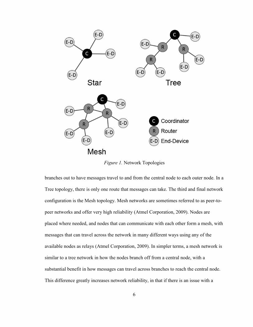
A ZigBee network can take on three different network topologies. As seen in
Figure 1, these include a Star topology, Tree topology, and Mesh topology. Each
configuration has its own advantages and disadvantages. Star networks are the simplest
of the three, and are thus the most used network configuration. As seen in the figure, it is
formed by outer nodes that communicate with a central node. One main disadvantage of a
Star network is due to the fact that there is only one route for messages to take, and any
interference or bottlenecking at the central node can cause trouble (Jennic Ltd, 2007). A
network based on a Tree topology has one central node, and in association with its name,
6
branches out to have messages travel to and from the central node to each outer node. In a
Tree topology, there is only one route that messages can take. The third and final network
configuration is the Mesh topology. Mesh networks are sometimes referred to as peer-to-
peer networks and offer very high reliability (Atmel Corporation, 2009). Nodes are
placed where needed, and nodes that can communicate with each other form a mesh, with
messages that can travel across the network in many different ways using any of the
available nodes as relays (Atmel Corporation, 2009). In simpler terms, a mesh network is
similar to a tree network in how the nodes branch off from a central node, with a
substantial benefit in how messages can travel across branches to reach the central node.
This difference greatly increases network reliability, in that if there is an issue with a
Figure 1. Network Topologies
7
node or communication is not possible due to interference, there is generally a multitude
of routes that messages can take to reach the central node.
Node Types
Similarly to network topologies, there are three types of nodes that are used in
ZigBee networks. These include a Coordinator, Router, and End-Device. A ZigBee
network can have up to 65,535 nodes in a single network, though all the nodes will be
composed of these three types (Jennic Ltd, 2007).
Coordinator
Whether using a Star, Tree, or Mesh topology, all networks must contain one and
only one Coordinator, which will be the central or root node of the network. As seen
earlier in Figure 1, it can be seen how the Coordinator is the central and most important
node in all three network configurations. One important task required by the Coordinator
is in system initialization. This includes selecting which frequency channel the network is
to use, usually by choosing the channel with the least amount of activity, as well as
starting the network and allowing other nodes to connect to and join the network. The
Coordinator is also capable of relaying messages between one node and another (Jennic
Ltd, 2007).
Router
The second type of node in a ZigBee network is a Router. For Mesh and Tree
topology networks, at least one Router is needed, as a Router has the ability to relay
messages and allow other nodes to connect to the network through them. Routers are
usually placed where their relaying abilities are put to use, passing on messages to and
8
from the Coordinator and other nodes. Like previously mentioned, a Coordinator also has
the ability to relay messages between nodes, and thus, a Star configured network does not
require a Router. In a Tree topology, Routers can only relay messages between the outer
branched out nodes and the Coordinator or parent Router connected on the same route
towards the Coordinator. As indicated earlier, Routers can communicate with other
Routers on separate branches to reach the Coordinator in a Mesh network topology.
Despite being redundant, Routers can be placed at the extremities of a network, though
their relaying abilities will not be put to use (Jennic Ltd, 2007). This is where End-
Devices come in.
End-Device
This final type of node is the simplest of the three. End-Devices, as their name
suggests, are always located at the very edges of a network, as seen in Figure 1. They
cannot relay messages between two other nodes, nor have other nodes connect to the
network through them like Routers can. In a Star topology network, End-Devices send
messages to either the Coordinator or to the other End-Devices through the Coordinator.
As mentioned, this is why Routers are not usually used in a Star network, as they would
be acting similarly to End-Devices. End-Devices are usually battery powered as they
have the ability to sleep so they can save power when not in use (Jennic Ltd, 2007).
Routers, and more obviously the Coordinator, lack the ability to enter low-power states in
order to uphold the network and maintain the capability of relaying messages.
Gateway
There is one other important type of ZigBee node not mentioned thus far
9
though—a Gateway. A Gateway will essentially allow a ZigBee network to communicate
with external systems and other networks. As a result, a ZigBee network will then have
the capability to integrate with co-existing systems, to join up in a larger global network
of underlying ZigBee networks, and to connect to many other IP devices (Atmel
Corporation, 2009). A Gateway is not an essential node to set up a ZigBee network, but a
useful option for creating a ZigBee network that may greatly increase in value by being
able to interface with the Internet.
Addressing
In a ZigBee network, every node requires some sort of identification. Two
addresses are therefore assigned to every device in a network. The first address, referred
to as an IEEE address or more commonly as a MAC address or extended address, is a
64-bit address chosen by the IEEE and is unique to each device (Jennic Ltd, 2007). The
second address in a ZigBee network is a local address. Simply dubbed a Network address
or short address, this 16-bit address is allocated to every device on the network by the
parent node, which can be either a Router or the Coordinator depending on the network
topology. The Coordinator in a network will always have 0x0000 as its local network
address (Jennic Ltd, 2007).
Software Architecture
The ZigBee software architecture is comprised of three different levels. These
three are described as a software stack, and include the Application level, ZigBee Stack
level, and Physical/Data Link level (Jennic Ltd, 2007). These three levels can be further
10
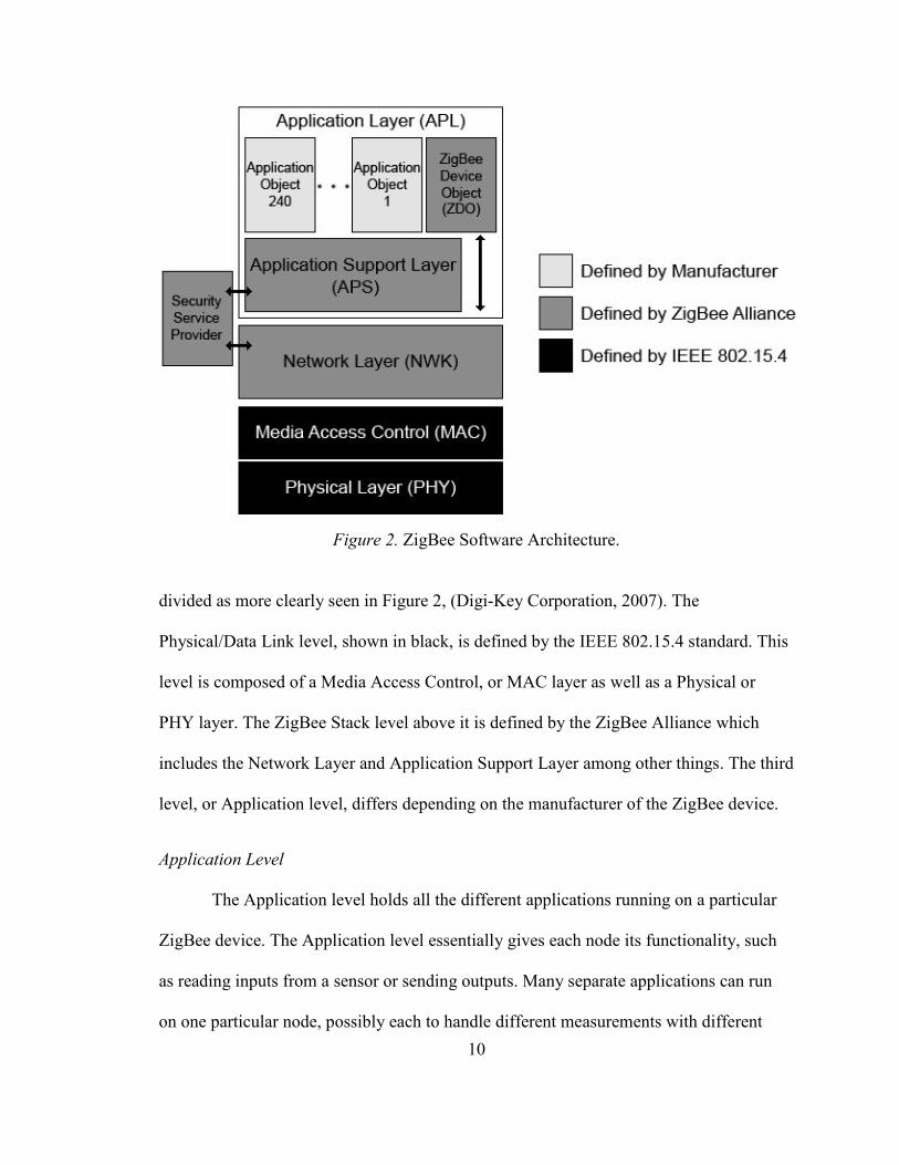
Figure 2. ZigBee Software Architecture.
divided as more clearly seen in Figure 2, (Digi-Key Corporation, 2007). The
Physical/Data Link level, shown in black, is defined by the IEEE 802.15.4 standard. This
level is composed of a Media Access Control, or MAC layer as well as a Physical or
PHY layer. The ZigBee Stack level above it is defined by the ZigBee Alliance which
includes the Network Layer and Application Support Layer among other things. The third
level, or Application level, differs depending on the manufacturer of the ZigBee device.
Application Level
The Application level holds all the different applications running on a particular
ZigBee device. The Application level essentially gives each node its functionality, such
as reading inputs from a sensor or sending outputs. Many separate applications can run
on one particular node, possibly each to handle different measurements with different
11
sensors at the same node. It is possible to include up to 240 different applications running
at one particular node (Jennic Ltd, 2007). In order to transmit messages between different
applications around a network, all applications must be given a particular identification.
Thus, each application running is labeled as an endpoint, with each application given and
endpoint number between 1 and 240. Using this endpoint association, a message can be
sent to a particular application on the entire network. This is done by using the local
network address of a particular node in conjunction with the node's application endpoint
number. Endpoint address 255 though can also be made use of. Otherwise known as the
broadcast endpoint address, any message transmitted to endpoint 255 will be sent to
every application on the node (Jennic Ltd, 2007). Endpoint 0 though is reserved on every
node for a specific application named the ZigBee Device Object, or ZDO, as seen in
Figure 2, which resides on all ZigBee devices. The ZigBee Device Object is responsible
for several functions. One important task includes dictating the type of node (i.e. whether
the device is an End-Device, Router, or Coordinator) that the ZigBee Device Object
resides on is. It is also responsible for initializing the node and playing a part in network
set-up (Jennic Ltd, 2007). The ZigBee Device Object is part of the ZigBee Stack level
and not the Application level though, as it is defined by the ZigBee Alliance.
ZigBee Stack Level
The ZigBee Stack level, briefly mentioned beforehand, is what supplies a device
with ZigBee functionality. It is in essence the bridge between the Application level and
Physical/Data Link level. The ZigBee Stack level controls the network structure, handles
all routing, and adds security to a network. This ZigBee Stack level as previously pointed
out earlier can be subdivided into the Application Support Layer (APS), Network Layer
12
(NWK), ZigBee Device Object (ZDO), and Security Service Provider or Security Plane.
The first layer, the Application Support Layer, decides upon which application to
message. This is done by using the particular application's endpoint address, and interacts
with the Application level through a Service Access Point (SAP) interface. To more
specifically detail the Service Access Point's communication, four types of operations are
used to pass information between the Application level and Application Support Layer.
These include requests, confirmations, responses, and indications (Jennic Ltd, 2007).
Generally, an application will send a request to the Application Support Layer, usually
followed by a confirmation as to whether the request is accepted or denied. A response is
then followed if applicable, and differs depending on whether the information is local to
the node or at a different node on the network. It will thus be a synchronous response if
the data can immediately be sent back to the application or an asynchronous response if it
requires time to acquire the information across the network. Lastly an indication is
somewhat of a reverse request, with the Application Support Layer sending information
or commands to the Application level, very likely due to requests from applications at
other nodes (Jennic Ltd, 2007). Back to the ZigBee Stack level, the second and important
layer is the Network Layer, defined by the ZigBee Alliance akin to the other elements of
the ZigBee Stack level. The Network Layer is responsible for several network tasks by
calling upon the Media Access Control layer in the Physical/Data Link level to perform
certain assignments. If the node in question is a Coordinator, the Network Layer in the
device will be responsible for starting the network. If the node is either a Coordinator or
Router, the Network Layer is also accountable in assigning network addresses to all child
nodes connected to this parent node. Similarly, the Network Layer has the ability to add
13
or remove any device from the network. Coordinators and Routers will also utilize the
Network Layer to route messages from different nodes to the properly addressed nodes.
Routers that are acting as End-Devices will simply not be using this function. The
Network Layer in all nodes will also provide the device with the ability to apply security
to any transmitted messages. Lastly, in a Mesh network topology, the Network Layer in
Routers will assist in executing route detection and storing routing table records to aid in
this purpose (Atmel Corporation, 2009). Aside from the ZigBee Device Object
mentioned earlier that is also part of the ZigBee Stack level, there also exists a ZigBee
Device Object management plane not shown in the earlier software architecture figure.
This management plane bridges the ZigBee Device Object with the Application Support
Layer and Network Layer to allow the ZigBee Device Object to communicate with these
two lower layers. Applications may sometimes request the ZigBee Device Object for
network access or security functions, and the ZigBee Device Object management plane
will allow the ZigBee Device Object to deal with these calls by using ZigBee Device
Profile or ZDP messages (Jennic Ltd, 2007). The last sector of the ZigBee Stack level is
the Security Service Provider, and is often called the Security Plane. As seen in the
earlier Figure 2, the Security Service Provider works together with the Application
Support Layer and Network Layer. Its purpose can be deduced quite easily, which resides
in security. Some of the included security features range from the management of
security keys, encrypting and decrypting data, as well as utilizing any hardware present
on the node to execute encoding and decoding duties efficiently (Jennic Ltd, 2007).
Physical/Data Link Level
The Physical/Data Link level is the last of the three levels present in the ZigBee
14
architecture. As briefly stated beforehand, the Physical/Data Link level is composed of
two layers, the Media Access Control or MAC Layer, and the Physical or PHY Layer.
These two layers are both based on the IEEE 802.15.4 wireless personal area network
standard. Ultimately, the Physical/Data Link level handles addressing and message
transmission and reception. As can be presumed, this level includes the actual transceiver
radio hardware (Digi-Key Corporation, 2007). More specifically, the Media Access
Control layer, which is sometimes called the Medium Access Control Layer, is
responsible for the addressing mentioned. For any messages that are being transmitted,
the Media Access Control Layer establishes where the message needs to be sent. Vice
versa, for any incoming message, the Layer ascertains where the message has come from.
The Media Access Control Layer is also in charge of constructing data packets or frames
of information that is to be transmitted, and likewise deconstructing any information data
packets that are received (Jennic Ltd, 2007). The later part of the Physical/Data Link
level, the Physical Layer, is involved in interfacing with physical transmission, and thus
contains the radio hardware. Data is sent and received over the air with the Physical
Layer with other nodes in a network. In addition, data is exchanged between the Physical
Layer and Medium Access Control Layer in every ZigBee Device to have messages
ultimately routed to the desired Application Object.
Transmission Characteristics
A ZigBee device comes with a high degree of reliability as the Physical/Data Link
Layer is based on the IEEE 802.15.4 standard as discussed. This IEEE standard offers
high dependability in several different ways.
15
Frequency Bands
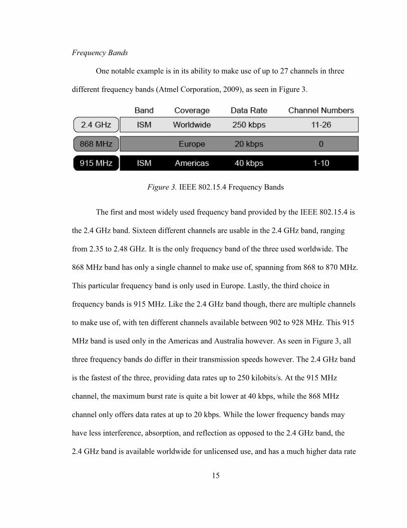
One notable example is in its ability to make use of up to 27 channels in three
different frequency bands (Atmel Corporation, 2009), as seen in Figure 3.
Figure 3. IEEE 802.15.4 Frequency Bands
The first and most widely used frequency band provided by the IEEE 802.15.4 is
the 2.4 GHz band. Sixteen different channels are usable in the 2.4 GHz band, ranging
from 2.35 to 2.48 GHz. It is the only frequency band of the three used worldwide. The
868 MHz band has only a single channel to make use of, spanning from 868 to 870 MHz.
This particular frequency band is only used in Europe. Lastly, the third choice in
frequency bands is 915 MHz. Like the 2.4 GHz band though, there are multiple channels
to make use of, with ten different channels available between 902 to 928 MHz. This 915
MHz band is used only in the Americas and Australia however. As seen in Figure 3, all
three frequency bands do differ in their transmission speeds however. The 2.4 GHz band
is the fastest of the three, providing data rates up to 250 kilobits/s. At the 915 MHz
channel, the maximum burst rate is quite a bit lower at 40 kbps, while the 868 MHz
channel only offers data rates at up to 20 kbps. While the lower frequency bands may
have less interference, absorption, and reflection as opposed to the 2.4 GHz band, the
2.4 GHz band is available worldwide for unlicensed use, and has a much higher data rate
16
than the lower frequencies. At first, it may not seem as if 250 kbps for a ZigBee device
with simple sensors would be necessary, or would in fact be clear overkill, but an easily
overlooked extra benefit from this rapid data transmission comes with the fact that less
power is used when transmission times are significantly decreased. One of the values
defining the ZigBee standard is in the desire to prolong battery life. Even if only
transmitting a few bits, efficiency is greatly increased if data is transmitted and received
rapidly (Atmel Corporation, 2009). A transmitter will always consume a given amount of
power regardless of how much data needs to be broadcast. By transmitting at the faster
data rate, the information is transferred much more quickly and allows the transmitter and
receiver to shut down just as rapidly to stop consuming power. In addition, to increase
dependability, if a ZigBee device has the appropriate hardware arrangement, it can be
configured to be able to use the many frequency channels available to it. In real time, the
device would be able to swap between the multiple channels to avoid any detected
interference or transmission issues (Atmel Corporation, 2009). Aside from switching
channels, there are several other reliability traits offered by the IEEE 802.15.4 standard.
Phase-Shift Keying
For the two lower frequency bands, 868 MHz and 915 MHz, binary phase-shift
keying, or BPSK, is available for use and defined by the IEEE 802.15.4 wireless standard
(Atmel Corporation, 2009). Phase-shift keying is fundamentally a modulation method in
which data is transmitted by modulating the phase of the carrier wave's frequency (Phase-
shift keying, 2009). Binary phase-shift keying, also referred to as PRK, Phase Reversal
Keying, or 2-PSK, is the simplest form of phase-shift keying. BPSK makes use of two
phases as out of phase as possile—180°, making this modulation scheme especially
17
vigorous as it is hard for demodulators to incorrectly interpret the data. Its significant
downside though, is that BPSK can only modulate 1 bit per phase at a time (Phase-shift
keying, 2009), and is therefore only appropriate for low data-rates, and is consequently
only used for the 868 MHz and 915 MHz frequency bands as indicated earlier. However,
offset quadrature phase-shift keying, or O-QPSK, is available if using one of the sixteen
2.4 GHz channels (Atmel Corporation, 2009). Offset quadrature phase-shift keying,
sometimes called Staggered quadrature phase-shift keying, or SQPSK, is yet another
phase-shift keying variant, or more specifically a slight modification of quadrature
phase-shift keying. Instead of using two phases as BPSK does, QPSK utilizes four
different phases equidistant from each other by 90°. By doing this, the QPSK modulation
scheme is able to either double the data rate as compared to BPSK, or maintain the data-
rate but halve the bandwidth. Improving upon the method, Offset QPSK simply offsets
the timing of bits to produce significantly lower amplitude instabilities generating a much
more desirable signal (Phase-shift keying, 2009). Thanks to these qualities that assist in
higher data rates, O-QPSK can be used by ZigBee devices when in operation at one of
the 2.4 GHz channels. As mentioned earlier, this higher data rate helps save a
considerable amount of power. At a given power level though, these higher data rates
commonly bring about degraded transmission range (Atmel Corporation, 2009). Though
as discussed, the benefits of longer battery life are more important to both the ZigBee
Alliance and the 802.15.4 standard, nevertheless other methods are put to practice to
improve transmission range.
Transmission Power
The ZigBee standard depends upon the IEEE 802.15.4 wireless personal area
18
network standard for its RF performance, and thus excels with its impressive long
battery-life and minimal power use for transmission as opposed to other powerful
wireless standards. In terms of power, the 802.15.4 standard dictates a nominal
transmitter output power of -3 dBm, or about 0.5 mW (Atmel Corporation, 2009). The
maximum output power allowed varies depending on which country the ZigBee device is
in use. In the United States, this amount is regulated by the FCC. As the 2.4 GHz and
915 MHz frequencies are part of the ISM band, this limit is set to 30 dBm or 1 watt that
can be supplied to the antenna. Post-antenna gain, the maximum Equivalent Isotropically
Radiated Power (EIRP), or simply the maximum amount allowed to radiate from the
antenna is 36 dBm or about 4 watts (Air802 LLC, 2005). This maximum amount though
will not nearly be needed or desired for a conventional ZigBee device. The 802.15.4
standard does specify however that any device should be capable of transmitting at least
0 dBm, or 1 mW of power, while the receiver sensitivity should allow a device to pick up
a signal of at least -85 dBm, or 3.16 x10⁻¹²
W (IEEE Computer Society, 2007). By using
a typical power output of -3 dBm in each ZigBee device, a reasonable amount of power is
conserved, proving very beneficial for battery-powered End-Devices while still
maintaining enough range to set up most ZigBee networks.
Range
The communication range between two ZigBee devices undoubtedly differs
depending on the transmitted output power. To clearly define range, it is the distance that
the transmitted RF signal is able to travel before the signal becomes too weak to detect by
the receiver. The difference in antennas, frequency used, and environment also noticeably
play a factor, but at the nominal output power of -3 dBm, it is generally easy to reach 10
19
to more than 100 meters from one device to another (Atmel Corporation, 2009). The
transmission range inside a house or building will greatly vary from the range done
outside, as it is possible to get much better transmission with a direct line of sight. Inside
a building, any walls or solid objects will greatly reduce the signal due to reflection,
absorption, standing wave effects, and diffraction (Jennic Ltd, 2007). Using an output
power of 0 dBm on a ZigBee device outdoors with a direct line of sight to the receiver, it
is usually easily possible to attain a transmission range of over 200 meters. It has been
shown that it is possible to reach a range greater than 450 meters with this same output
power outdoors (Jennic Ltd, 2007). Indoors, ranges of at least 30 meters are generally
possible when transmitting using an output power of 0 dBm. Much higher-powered
ZigBee devices do exist however and if a greater range is required from one node to
another, modules outputting over 15 dBm of power can commonly realize ranges five
times greater than the standard lower powered devices (Jennic Ltd, 2007). This would
effectively increase the line of sight range to over 2250 meters. Frequently when ranges
of this magnitude are necessary it is not uncommon to see the use of the 915 MHz
frequency bands in the United States. Signal waves at a frequency of 915 MHz are longer
than those at 2.4 GHz and consequently travel further. Some excellent examples of long
range devices include Digi's wireless products. For ZigBee products, their XBee-PRO
DigiMesh 900 RF module which operates at the 915 MHz bands offers the longest range
(Digi International Inc., 2009). Using high gain antennas, it is capable of transmitting up
to six miles in a direct line of sight outdoors. Moreover, it does not even come close to
the maximum allowed output power, as it has a power output of 17 dBm or 50 mW.
Digi's XTend RF Modem further illustrates high output power at low frequency use (Digi
20
International Inc., 2009). It is not a ZigBee product, but does operate in the 915 MHz
ISM band like a ZigBee device could. By using the maximum allowed output power of
30 dBm regulated by the FCC, the modem has a surprising outdoor line of sight range of
up to 40 miles. After all is said and done though, these long ranges will not particularly
benefit or be of much use to the most common ZigBee networks. It is important to note
the types of network topologies that a ZigBee network can consist of when regarding
range, as the network functions that ZigBee provides greatly assist in any shortcomings
regarding transmission range. One particular ZigBee device may only need to
communicate with a node that is relatively nearby, and the Coordinator or other distant
nodes may very well be way out of reach to the device. Routing features present on
Router nodes and Coordinators will assist in having any messages hop from one node to
another until the destination is reached. Doing this, it would be easy to create a network
spanning thousands of meters (Atmel Corporation, 2009), all while using low output
power and faster 2.4 GHz transmission.
Latency
Every ZigBee network will differ in requirements, with some desiring data to be
transmitted extremely quickly, while others not nearly as fast. In general, most networks
will place priority on increasing battery-life as opposed to low data latency. By reducing
data latency requirements, a network will commonly gain the benefit of having longer
battery-life. When choosing a network topology to use, Star networks generally have the
lowest data latencies. This is because the farthest a message will ever have to travel is
from one End-Device to another, using the Coordinator as a stepping stone. A ZigBee
network set up in a Star configuration can transmit data from one End-Device to another
21
in as quickly as ~16 ms; moreover this speed is while the network is making use of
guaranteed time slot features, or otherwise termed a beacon-centric network (Atmel
Corporation, 2009). Time slots are used so that two messages sent to the same node do
not collide with each other. If yet even lower data latency is required, it is possible to
disable the time slot features but risk any collision that may occur if messages are
transmitted synchronously. Tree and Mesh topology configured networks may have
noticeably higher data latency depending on the amount of routing hops that need to be
performed, though it is not uncommon to have data transmitted across the network
relatively infrequently for sensor data that is not needed very often. These nodes though
that do not transmit often are usually in sleep modes to preserve power. A typical ZigBee
End-Device will take about 15 ms to transition to active if in its low power sleep state
(ZigBee Alliance, 2009). This is however very low when compared to other wireless
networking standards.
Comparison with Other Standards
Of the many other wireless networking alternatives, ZigBee is often most
compared to Bluetooth. This is most likely due to Bluetooth's popularity and the fact that
both ZigBee and Bluetooth are made for data transfer over moderately short distances.
Bluetooth is an open wireless protocol whose networking standard is based on the
IEEE 802.15.1 personal area network standard, and over recent years has made its way
to be put to use into a variety of differing products ranging from mobile and home phones,
notebooks and personal computers, printers, GPS receivers, cameras, and video game
consoles (Bluetooth, 2009).
22
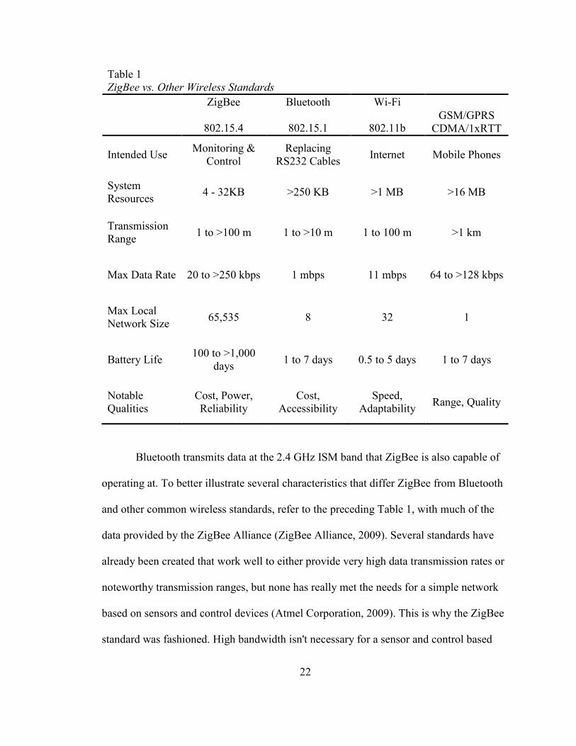
Table 1
ZigBee vs. Other Wireless Standards
ZigBee
802.15.4
Bluetooth
802.15.1
Wi-Fi
802.11b GSM/GPRS
CDMA/1xRTT
Intended Use Monitoring &
Control
Replacing
RS232 Cables Internet Mobile Phones
System
Resources 4 - 32KB >250 KB >1 MB >16 MB
Transmission
Range 1 to >100 m 1 to >10 m 1 to 100 m >1 km
Max Data Rate 20 to >250 kbps 1 mbps 11 mbps 64 to >128 kbps
Max Local
Network Size 65,535 8 32 1
Battery Life 100 to >1,000
days 1 to 7 days 0.5 to 5 days 1 to 7 days
Notable
Qualities
Cost, Power,
Reliability
Cost,
Accessibility
Speed,
Adaptability Range, Quality
Bluetooth transmits data at the 2.4 GHz ISM band that ZigBee is also capable of
operating at. To better illustrate several characteristics that differ ZigBee from Bluetooth
and other common wireless standards, refer to the preceding Table 1, with much of the
data provided by the ZigBee Alliance (ZigBee Alliance, 2009). Several standards have
already been created that work well to either provide very high data transmission rates or
noteworthy transmission ranges, but none has really met the needs for a simple network
based on sensors and control devices (Atmel Corporation, 2009). This is why the ZigBee
standard was fashioned. High bandwidth isn't necessary for a sensor and control based
23
network, and the ZigBee standard was designed to create a low-latency network that is
able offer very low power consumption for long battery-life. Instead of creating it as a
propriety wireless system, the ZigBee standard is able to provide interoperability between
multiple ZigBee devices, similarly to how Bluetooth devices can interact with one
another. Four different types of networks are displayed in the previous table including
ZigBee, Bluetooth, the basic Wi-Fi standard 802.11b, and GSM/GPRS and
CDMA/1xRTT which are used for mobile phones. The mobile phone standards are
obviously intended for transmitting at long distances and offer a reach in excess of 1 km.
Local 802.11b Wi-Fi networks generally cannot transmit from one device to another
farther than 100 meters apart, and depending on the circumstances, even ZigBee can
surpass this. Bluetooth however is designed to transmit even shorter distances, with most
devices limited to about 10 meters (Bluetooth, 2009). On the other hand, Bluetooth does
offer data rates up to four times faster than ZigBee can employ when both utilize the 2.4
GHz band, while lower frequency use by ZigBee devices will significantly lower data
rates as earlier pointed out. ZigBee devices though can surpass the data rates that mobile
phones generally achieve using the standards shown. 802.11b, despite being slow
compared to other newer Wi-Fi standards, is still a great deal faster in data rate
transmission in comparison with ZigBee, Bluetooth, and mobile phones. Of the several
standards, there is no question in ZigBee's superiority in terms of possible network size.
For practical purposes, it is pretty much possible to create as large a network as desired
when using ZigBee, as it is only limited by the amount of addresses the network can
assign, which is 2^16 devices. Bluetooth was designed for only a small amount of
devices to network with each other, while mobile phones were not even made to network
24
with one another. As seen in Table 1 as well, ZigBee based on the 802.15.4 standard is
clearly the network of choice when long battery-life is sought. Mutually, devices that
utilize Bluetooth or Wi-Fi as a method of communication, and even more obviously
mobile phones, are in constant need of being recharged or powered externally. Because
of this, certain networks greatly benefit from ZigBee use, and not solely due to power
conservation. Node placement in particular networks can be particularly troublesome
when not using a battery powered device. A battery operated ZigBee End-Device could
be placed in a difficult to access location away from any external power sources without
having to check up on it for many years if it is not constantly transmitting data often and
its sleep features are used. ZigBee is also a very cost-effective solution when used
compared to other network standards, and devices that utilize ZigBee or the 802.15.4
standard can be manufactured at a cheaper cost as compared to Bluetooth and the other
wireless standards. To be specific, as of a few years ago, the selling price of an 802.15.4
ZigBee capable transceiver was about $1, while the cost of a radio, processor, and
memory package was about $3 with prices continuously declining (Adams & Heile,
2006). The ZigBee standard is thus ideal for sensor and control networks that consume
very little power, while having the ability to accommodate an almost unlimited amount of
possible network nodes, and offers a data rate and transmission range that is more than
acceptable for its general intended use. One term not yet referenced as of yet is ZigBee's
very low duty cycle. This low duty cycle, or the ratio of on time to off time, is a main
reason in ZigBee's very long battery life, and as can be guessed, is much lower when
compared to Bluetooth (ZigBee Alliance, 2009). A ZigBee node will be able to stay
dormant for very long periods of time without any communicating. In comparison with
25
other wireless standards, ZigBee is very inexpensive, much more efficient, and can create
much larger local networks.
Companies Making use of ZigBee
A multitude of companies make up the membership of the ZigBee Alliance. As
brought up previously, it is necessary to join as a member to create commercial ZigBee
products. Summed up, there are a total of over 300 members capable of producing
ZigBee devices for market. Of these, the major players that are designated as promoters
who pay $50,000 yearly to assist in maintaining the ZigBee standard and creating ZigBee
products include Ember Corporation, Freescale Semiconductor Inc., Huawei
Technologies, Itron Inc., Landis+Gyr, Royal Philips Electronics, Reliant Energy Inc.,
Samsung Electronics Co., Ltd., Schneider Electric, Siemens AG, STMicroelectronics,
Tendril, and Texas Instruments Inc. (ZigBee Alliance, 2009). Each of these companies
along with the other hundreds of members contribute to the ZigBee standard in different
ways.
Freescale Semiconductor, Inc.
Freescale Semiconductor Inc., as noted, is one of the many companies actively
involved in the ZigBee Alliance and in creating ZigBee products. Freescale first began
their ZigBee lineup with the MC1319x family. Freescale's approach in their first design
with the MC1319x was to split the hardware and software at the Physical, or PHY Layer.
The Freescale MC13193 is a transceiver made to operate at the 2.4 GHz frequency bands
where most of the Physical Layer functionality resides. The Media Access Control Layer,
Network Layer, and Application Layer all exist as software in the microcontroller as seen

26
Figure 4. Freescale MC13193 Architecture
in Figure 4 above. The microcontroller communicates with the MC13193 transceiver via
a standard 4-wire Serial Peripheral Interface, or SPI (Digi-Key Corporation, 2007). As
pictured above, the microcontroller is split from the MC13193 transceiver made up of the
Physical Layer. By doing this, custom solutions can be designed based on different
microcontroller needs. For ZigBee devices that are to be set up as End-Device nodes that
require very little computational power and do not necessitate a large amount memory, a
cheaper low memory 8-bit microcontroller can be used. For a device demanding a lot
more capability, such as a ZigBee Gateway, a more sophisticated 32-bit microcontroller
can be joined up with the transceiver (Digi-Key Corporation, 2007). The software that
27
makes up the Media Access Control Layer was designed by Freescale, and as observed in
previous figure, Figure 8 Wireless, who partnered up with Freescale, integrated
Freescale's Media Access Layer with their own Network Layer to help create Freescale's
first generation stack named Z-Stack (Digi-Key Corporation, 2007). With ZigBee's
simplicity in mind, a toolset co-developed by Freescale and Figure 8 Wireless is offered
to original equipment manufacturers to facilitate in the creation of Application Objects.
Of the three initial transceiver designs, the MC13191, MC13192, and MC13193, only the
later provides ZigBee support. The other two will not be able to make use of many of the
advanced ZigBee networking features. It is possible to set up simple network
configurations such as point-to-point or Star networks without the use of ZigBee, and
thus cheaper transceivers such as the MC13191 and MC13192 can be used (Digi-Key
Corporation, 2007). The MC13193 transceiver has a nominal output power of 0 dBm, or
1 mW, which can be tweaked to output as low as -16 dBm up to a maximum of 3.6 dBm,
all while operating at 2.4 GHz with a maximum data rate of 250 kbps. Its receiver has a
sensitivity of -92 dBm (Digi-Key Corporation, 2007). The Z-stack software and
Freescale's Media Access Control software was designed with the HCS08
microcontroller in mind. As the HCS08 requires a supply voltage of 3 V, it can be easily
paired up with an MC1319x transceiver that can also operate at this voltage, providing an
ideal solution for battery powered devices, all while offering an ample assortment of
modes of operation to assist in power conservation (Digi-Key Corporation, 2007). The
five possible transceiver states that the MC1319x features include idle, doze, hibernate,
transmit, and receive. Idle is the typical inactive state from which the transceiver switches
to one of the other four states. About 0.5 mA will be drawn by the transceiver while in
28
this mode. The second state, Doze, is especially useful to assist in both extending battery
life as well as allowing extremely fast wake up time. While in doze mode, the transceiver
is able to wake up in as little as 0.5 ms. By comparison, it would usually take as much as
23 ms for the transceiver to toggle to receive or transmit mode from off. In Doze mode,
the transceiver current draw drops to approximately 35 µA. To be able and preserve even
more power, the third state, Hibernate, can be used. By sacrificing speedy wake up time,
the current draw of the transceiver can be lowered to roughly 2.3 µA. It will take
approximately 20 ms to return to idle from hibernate mode however. Transmit and
receive modes need not an explanation, but in terms of current use, transmit will draw
about 30 mA while receive mode will draw even more at almost 37 mA (Digi-Key
Corporation, 2007). It is important to mention however that the MC1319x family of
transceivers is composed of an analog receiver and corresponding antenna, as well as an
analog transmitter with its own separate antenna. This is where Freescale's second
generation ZigBee platforms, the MC1320x and MC1321x, come in. By design, the
MC1320x is very similar to its predecessor, but has one clear difference. With regards to
the transceiver, a newly introduced integrated transmit/receive switch allows both the
analog receiver and analog transmitter to use the same antenna. This design change helps
lower the amount of off-chip components necessary, although aside from this change, the
transceiver shares the same features and specifications as its precursor (Digi-Key
Corporation, 2007). To increase accessibility, the previously mentioned Media Access
Control and Z-Stack software used on the MC1319x family can also be used with
MC1320x transceivers, and likewise with the MC1321x family. Akin to the earliest
designed models, only one of the MC1320x models, the MC13203, is able to make use of
29
Z-Stack and ZigBee. Lastly, like the MC1320x, the MC1321x family incorporates the
newly introduced transmit/receive switch making use of a single antenna. The MC1321x
series further innovates from Freescale's the first generation however, by combining an
HCS08 GT based microcontroller with an MC1320x transceiver. This new System in a
Package, or SiP, helps decrease cost by further adding to the benefit of reduced off-chip
components and board space (Digi-Key Corporation, 2007). In this particular series, the
MC13214 package provides ZigBee support. Likewise, the MC1321x series shares all
transceiver specifications and features from the previous models. To briefly compare
Freescale's first generation MC1319x and second generation MC1321x containing an
internal microcontroller, off-chip required component count has decreased from 17 to 10,
while the total solution size has decreased from 300 mm2 to 200 mm
2 (Digi-Key
Corporation, 2007). The MC1322x series, Freescale's third generation ZigBee platform,
was made available recently. This design further enhances integration and power
efficiency for ZigBee modules. One other unmentioned Freescale toolkit is BeeKit.
BeeKit further assists developers, providing them with a straightforward GUI to
configure and test networks based on Freescale's ZigBee modules, allowing developers to
focus on making applications (Freescale Semiconductor, Inc., 2009). For starting
developers, there are several development tools and evaluation kits made available by
Freescale based on the multiple generations of ZigBee transceivers to assist and
demonstrate in the capabilities of ZigBee and wireless networking. More companies
making use of the ZigBee standard will be mentioned in specific uses of ZigBee.
ZigBee Uses
A number of application profiles are published by the ZigBee Alliance to help
30
original equipment manufacturers and vendors develop products that can easily
communicate with one another. These application profiles, mentioned beforehand,
include some of the more popular uses of ZigBee. Multiple markets already exist and
have been putting ZigBee to good use. Of the many possible uses of ZigBee, some of the
most popular sectors which have been making the most out of ZigBee networks include
consumer electronics, energy management and efficiency, health care, home automation,
building automation, as well as Telecom and Wireless Sensor Applications (ZigBee
Alliance, 2009). The consumer electronics market deals with the RF4CE Consortium to
help create a widely used remote control RF standard, while utilizing ZigBee in energy
management and efficiency is commonly referred to as ZigBee Smart Energy. Use in
health care can vary in location with ZigBee providing reliable monitoring networks.
Home and building automation making use of ZigBee's specialties enable different levels
of control, conservation, convenience, and safety (ZigBee Alliance, 2009). ZigBee's
service in telecom applications can significantly improve or add upon telecom network
functions, while wireless sensor applications can undoubtedly benefit from monitoring
tasks that ZigBee can lend a hand in (Jamieson, 2008). As discussed beforehand, multiple
ZigBee application profiles exist or are currently in development to assist in specifying
guidelines and providing interoperability with the multitude of ZigBee devices possible
for many of these markets. Aside from ZigBee's use in automation, several markets such
as the use of ZigBee as RF remote controls, ZigBee in energy management and efficiency,
and ZigBee in healthcare currently look very promising for the ZigBee standard to
become a prominent wireless networking standard.
31
ZigBee RF4CE
The ZigBee RF4CE aims to be a prevalent standard in remote controls for
consumer electronics. Recently, on March 3, 2009, the RF4CE Consortium joined up
with the ZigBee Alliance to create a standardized specification for remote controls that
operate by use of radio frequency. The RF4CE Consortium was established on June 12,
2008 by Panasonic Corporation, Royal Philips Electronics, Samsung Electronics Co., Ltd.
and Sony Corporation (ZigBee and RF4CE Set New Course For Consumer Electronic
Remote Controls, 2009). This new standard aims to combat many of the disadvantages
found on infrared remotes by providing a remote control alternative capable of working
in conjunction with devices from multiple manufacturers by using the reliable, straight-
forward, and inexpensive traits that a ZigBee network can offer. The ZigBee RF4CE
standard was developed in particular for simple communication between two devices
without employing the more complex network topologies available to ZigBee modules.
By using RF remotes using ZigBee for transmission, it is also possible for the controlled
devices to transmit data back to the remote, adding to the immersion. ZigBee RF4CE
devices will also have the power to interact with any other network of ZigBee devices,
possibly enhancing any home networks. The ZigBee RF4CE standard dictates operation
in the 2.4 GHz frequency band using three different possible channels. The RF4CE
standard also specifies two types of nodes possible in a network, a target node, and a
controller node (ZigBee Alliance, 2009). Target nodes or simply the devices that are
being controlled have abilities similar to that of a standard Coordinator, while controller
nodes are more like End-Devices that pair up with a particular target node. Manufacturers
are already planning products for release in 2009. Numerous types of consumer products
32
can benefit from the use of ZigBee RF4CE, some of which include home entertainment
and home theater products, garage doors, and keyless entry systems (ZigBee Alliance,
2009). While the ZigBee RF4CE specification is still just starting off, it has a great
possibility of spreading out to many homes and becoming a very reliable widely used
standard.
ZigBee Smart Energy
ZigBee Smart Energy deals with energy management and efficiency, and simply
put, provides utility companies with dependable and practical home area networks so that
they can better manage energy (ZigBee Alliance, 2009). The smart energy application
profile published by the ZigBee Alliance has already been created, with market and
technical requirements already documented, profile specification complete, and is
currently undergoing testing (Jamieson, 2008). This application consists of more than
simply reading meters automatically, and gives both utility companies and consumers the
capability to create a home network consisting of multiple smart appliances (ZigBee
Alliance, 2009). The multiple ZigBee Smart Energy features include advanced metering,
demand response and load control, pricing, text messaging, sampling devices, and
security, while the benefits from the use of ZigBee Smart Energy include affordability,
ease of use, reduced energy consumption, and reduced environmental impact (ZigBee
Alliance, 2009). Regarding advanced metering, it is possible to take multiple forms
measurement such as load profile, power factor, summation, demand, and tiers, and
measurements do not necessarily have to relate to electricity, and can also include water,
gas, and thermal utilities (ZigBee Alliance, 2009). Pricing meanwhile will allow these
multiple utilities to display real-time pricing based on consumption with support in
33
multiple countries and currencies. Smart energy networks would provide advanced
security using certain key cryptography methods and data encryption (ZigBee Alliance,
2009). ZigBee Smart Energy is not solely intended for home residential use however, and
can be of great help to the industrial and commercial sector as well. The ZigBee Smart
Energy profile assists manufacturers who design and create these home networking
devices, and greatly benefits both residential and commercial/industrial users as well as
the utility companies themselves. Manufacturers will be able to provide networking
products relative to this focus that are interoperable between different vendors. These
manufacturers will be able to expand and enter a new growing market helping consumers.
For Utilities, ZigBee Smart Energy networks will assist in delivering reliable energy as
well as in increasing efficiency and lessening the need of constructing more generation
plants (ZigBee Alliance, 2009). Lastly, for consumers, products based on the smart
energy profile will be of assistance in many ways. The first would be in helping lower
energy costs, all while employing a simple to use wireless network that will not require
the need of wiring, providing many features beneficial to consumers. Real-time pricing
and usage information will help coerce consumers into consuming less power, and in turn
helping reduce adverse impacts on the environment in the process (ZigBee Alliance,
2009). A large number of companies are already creating and selling products that utilize
ZigBee and the ZigBee Smart Energy profile. Some of these include Alektrona
Corporation, Landis+Gyr, Computime, Comverge, Daintree Networks, Inc., Ember
Corporation, Energate Inc., Greenbox Technology Inc., Itron Inc., LS Industrial Systems
Co., Ltd., LS Research, LLC, PRI Ltd., National Technical Systems, Inc., Tendril
Networks, Inc., Trilliant Incorporated, TÜV Rheinland Group, and Wireless Glue
34
Networks, Inc. (ZigBee Alliance, 2009). Products designed by these companies range
from ZigBee enabled metering devices, to monitoring gadgets, to smart thermostats and
even to software solutions that may help automate or add functionality to a ZigBee Smart
Energy network.
ZigBee Health Care
ZigBee Health Care falls under the Personal Home and Hospital Care application
profile. ZigBee's use in health care is designed to be put to use to manage and monitor
noncritical devices that assist in several common chronic diseases (ZigBee Alliance,
2009). By providing more information regarding ones health, ZigBee Health Care
attempts to encourage and assist in aging independence, chronic disease management,
and overall health and wellness by using inexpensive, secure, easy to use, and
interoperable devices (ZigBee Alliance, 2009). Devices designed with this profile are not
solely made for hospital use, but to be of use in homes, nursing homes and elderly care
centers, active adult communities, and fitness centers. Trying to better peoples' lives and
add convenience, ZigBee Health Care aims to benefit health and fitness, reduce in-patient
stays, and lower health related costs (ZigBee Alliance, 2009). Many types of devices
made for a variety of uses can be made. A glucose meter for example could measure the
estimated glucose in the blood of an individual with diabetes, while a pulse oximeter will
instead measure the oxygen in the blood of a patient (ZigBee Alliance, 2009). While
devices like these do not require ZigBee by any means, much can be done if they are
somehow connected to a network. Many of these devices are intended to be used at least
once a day. If they are equipped to connect to a wireless network, monitored information
can constantly be transmitted to a central location node on the network. This local
35
network can then be optionally connected to an external monitoring center where a
caretaker or family member may be of assistance should any problem occur (ZigBee
Alliance, 2009). Caretakers will be also able to tell whether a person is actively
performing the necessary check-ups. Other simple devices such as ZigBee enabled
weighing scales or blood pressure meters could also very appropriately be of value in this
situation. It can be seen how circumstances like this can greatly benefit the elderly and
why the ZigBee Personal Home and Hospital Care application profile put a lot of
consideration into assisting in this area. Elderly or others that may need constant
supervision may very well wear certain networked devices constantly monitoring them.
These may include devices such as pulse monitoring or blood pressure monitoring.
Electrocardiographs monitoring a person's heart will also provide mobility while under
constant supervision. Fall detectors can also be used to automatically signal an alarm
should a person fall, or likewise, a panic button worn by the person could so the same,
with either device capable of optionally including voice communication to speak to the
caretaker or family member who may receive the distress signal (ZigBee Alliance, 2009).
Wireless sensor networks is a very rapidly growing field in the healthcare industry.
Global sales could reach up to $7 billion dollars within the next ten years, and this year,
there will likely be up to a million wirelessly networked healthcare devices sold, with a
40% to 50% yearly sales growth rate over the next ten years (ZigBee Alliance, 2009).
Health related products making use of ZigBee will greatly assist in monitoring patients
with chronic diseases, those that need constant supervision, and promoting overall
physical fitness.
36
III. HOME AUTOMATION
Home automation, sometimes referred to as smart homes, along with commercial
and industrial automation, is one of the primary market targets for use with the ZigBee
platform. As mentioned earlier, ZigBee's four main goals in this area include control,
conservation, convenience, and safety (ZigBee Alliance, 2009). From lighting, to
ventilation systems, it is possible to automate and control a large number of devices and
appliances. Using cleverly implemented systems, doing this will greatly assist in
conserving energy and monitoring energy use. In terms of convenience, ZigBee is
wireless allowing a local easy to use network without the need for wires, and many
devices will be able to be controlled from multiple locations, and in living to its name,
automatically if desired. For safety, many devices are aimed at providing security and
monitoring conditions to guarantee wellbeing using a ZigBee secure network (ZigBee
Alliance, 2009). Using inexpensive technology easily capable of handling enough data to
monitor and control a complex network, and making use of the many ZigBee features
already discussed, it can be seen why ZigBee is a very good fit for automation purposes.
These features range from the possible network topologies such as mesh networking to
overcome any range limitations, to long battery-life, to ease-of-use, to the many possible
interoperable devices possible that can be of use in a ZigBee network. As the ZigBee
Alliance has stated, "industry experts believe ZigBee will change the way the average
person thinks of controlling elements in the home" (Vision for the Home - ZigBee
37
Wireless Home Automation, 2006). There are multiple ways to approach designing a
home automated network, and ZigBee is only one of the many options to consider when
designing a home automation system, with a variety of ways to implement a network
both wirelessly and wired, each with different features and transmission characteristics.
Standards and Systems
As pointed out, an automation network can be set up in many different ways with
many different communication standards already in existence. Among these standards,
many are wireless like ZigBee, and some are wired. Wired connection methods may
provide higher data transfer rates, but for networks that desire convenience and only
require simple control and monitoring, wireless greatly excels. Regarding other wireless
technologies and standards, "ZigBee overcomes speed limitations found in other wireless
home automation technologies and opens greater possibilities to use more devices on a
single network" (Vision for the Home - ZigBee Wireless Home Automation, 2006). To
group the different types of standards, there are three classifications regarding home
networking technologies, including device interconnection, data nets, and control and
automation nets (Home automation, 2009). Device interconnection and data nets are
common among computer use, with device interconnection including standards like
Bluetooth, USB, and FireWire, while Data nets include the popular Ethernet and Wi-Fi
standards. The ZigBee standard falls under control and automation nets, with other
standards and protocols such as X10, OpenWebNet, ONE-NET, LonWorks, EnOcean,
and Konnex (Home automation, 2009). Bridges can be created that can "bridge" two
types of communication standards together, allowing information to be transferred
between two types of networks. By definition, the three elements that usually make up a
38
home automation system include hardware or software controllers, sensors, and actuators
(Home automation, 2009). Using these three types of building blocks, it is possible to
form three types of automated networks. These include a centralized architecture,
distributed architecture, and a mixed architecture (Home automation, 2009). These
designs operate as their name implies. A centralized system will contain a central
controller sending all the control signals to different actuators, while receiving all the
information from the many monitoring sensors. In a distributed network all the sensing
and actuator devices will contain the intelligence. Lastly, a mixed system will also
contain sensors and actuators with intelligence to process information from other devices,
but are linked to other smart nodes to deliver information (Home automation, 2009).
Utilizing the many types of communications and systems to create a home automation
network, many different types of devices and tasks can be performed to add control,
increase convenience, help conserve, and provide safety.
Tasks
There are many possible tasks involved to make any home a smart home. To more
easily envision the possibilities, CE@Home's short narrative describes what an advanced
home automated network can feel like while including numerous task examples:
You arrive home from a long day at work. As soon as you use your digital key to
unlock the door, your house adjusts the lighting, heat, and window blinds to your
liking and puts on your favorite CD in the kitchen. While you were at work, the
house fed the cat, turned off the space heater your kids accidentally left on in the
basement, and recorded motion-triggered video from security cameras around the
property. Your refrigerator detected an almost empty milk carton and added a
39
gallon of 2% to the shopping list that it will e-mail to you on Friday. Your house
was ready to detect water or gas leaks, freezing pipes, and fire and could have
called you, the fire department or a plumber. (Vision for the Home - ZigBee
Wireless Home Automation, 2006)
From the above, it can be seen how varied home automated tasks can be. Many
tasks are common to almost all automated networks, while some are more specific and
cater each user's preferences and demands. Two of the more popular tasks to integrate
into a home automation network involve ventilation and lighting. Ventilation may
involve any type of heating or cooling system and all of its associated monitoring and
control devices. These may include heating or cooling units and their respective
thermostats to monitor temperature and humidity, pumps and pump controllers, pressure
sensors, flow sensors, and even exhaust and ceiling fans (Jamieson, 2008). Lighting on
the other hand, involves multiple ways to automatically control a home's illumination.
This may range from automatically controlling each electrical light controlled by the
network, to adjusting lighting based on ambient conditions. Devices that can be made in
this category include simple on/off lights, dimmable lights, color dimmable lights, on/off
and dimmable switches to control these lights, as well as ambient light sensors and
occupancy sensors (Jamieson, 2008). Ambient light and occupancy sensors will greatly
assist in automating the lighting. Light sensors can be used to tell whether a light should
be needed or not based on ambient conditions, and in the case of dimmable lights, how
bright to adjust them. Occupancy sensors are somewhat more complex and can be
implemented in different ways. For lighting, they can greatly assist in having the network
know whether a person is in a particular room or not, and to adjust the lighting
40
appropriately. Lighting may not only entail electrical lighting however, but natural
lighting as well. Natural lighting may involve any shade and shade controller, drapery,
and awning that can be connected to the network and be controlled wirelessly,
automatically or not. A more advanced method that may be more popular in the future
includes LCD films on windows to shade from natural lighting (Home automation, 2009).
Ventilation and lighting controlled by a home network greatly add to the ability to
conserve power. Air Conditioning and heating units can drain a lot of power if not
managed properly, and lighting that is automatically controlled can efficiently conserve
energy, particularly when using ambient light and occupancy sensors. Two other
segments that can benefit from being connected to a home network include audio and
video products. This can include several types of electronic products or switches to
control existing electronic products as well. Multiple types of home theater products
ranging from TVs to home stereos that are wirelessly networked will be able to be
controlled automatically or from remote locations. On the subject of audio, whether for
music, communication, or an alarm system, speakers and microphones placed all around
a house can complement a smart home as well by creating an intercom system.
Concerning alarm systems, security is one of the key features that benefit from the use of
home automation. This applies to both security and health safety. Surveillance security
and intruder alarm systems can be integrated to a home network using several types of
sensors detecting movement, sensors detecting glass breaking, and magnetic sensors on
doors and windows (Home automation, 2009). Many other types of safety can be
controlled by use of sensors monitoring conditions in and outside of a house. This may
include sensors detecting any fire/smoke, water leaks, or gas leaks. Any medical related
41
monitoring or panic button devices or can also be networked. While not necessarily a
common use currently, robotics in home automation further adds to the possibilities.
Wireless robots could be controlled by the home network to assist in a particular task that
the robot is designed for. A great deal of devices not mentioned thus far are also very
common and useful in a home automation network. These may range from simple on/off
switches to control almost any device, to wireless remote controls, and even to useful
range extenders that simply help guarantee communication between multiple wireless
nodes of a network (Jamieson, 2008). Even more specific, almost any device or appliance
can be designed to make use of a home network such as garage doors, coffee makers,
garden products, swimming pool pumps, and pet feeders (Home automation, 2009). It can
be seen how varied an automated home can be in how there exists an almost endless
amount of possible devices that can be used. Whether using ZigBee or not, home
automation will greatly add to the convenience and security of a home while assisting in
providing easy to control devices and making power conservation easier.

42
IV. POWER CONSERVATION
Power conservation, otherwise known as energy conservation, is the practice of
reducing energy use through whatever methods possible. This can be done through
efficient energy use by means of unique products, or by simply attempting to draw less
electricity. Power conservation is an important subject matter worldwide, and is
becoming an ever increasing topic as energy consumption greatly affects the environment
on a global scale.
Statistics
As stated, power conservation has been a growing importance globally. Currently
the United States is the country that consumes the most amount of energy, with energy
sectors subdivided into transportation, residential, commercial, and industrial. Adding up
all the sectors, as of 2004 the industrial sector utilized 33% and the most energy in the
United States, with transportation at 28%, residential at 21%, and lastly commercial at
17% (Energy conservation, 2009). The industrial division is made up of all production,
manufacturing, construction, farming, water management, and mining. Saving energy
equates to saving money, and thus many improvements have been made in the industrial
sector to conserve power. The transportation section is made up of any personal or cargo
vehicle. This sector is mostly dependent on gasoline however, with about 65% of energy
in this sector eaten up by gasoline powered vehicles, mostly for personal use (Energy
conservation, 2009). Ironically, in this sector electricity use is actually encouraged. For
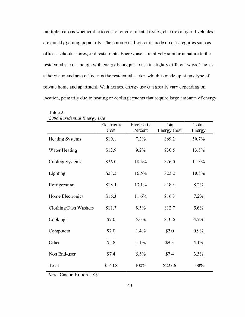
43
multiple reasons whether due to cost or environmental issues, electric or hybrid vehicles
are quickly gaining popularity. The commercial sector is made up of categories such as
offices, schools, stores, and restaurants. Energy use is relatively similar in nature to the
residential sector, though with energy being put to use in slightly different ways. The last
subdivision and area of focus is the residential sector, which is made up of any type of
private home and apartment. With homes, energy use can greatly vary depending on
location, primarily due to heating or cooling systems that require large amounts of energy.
Table 2.
2006 Residential Energy Use
Electricity
Cost
Electricity
Percent
Total
Energy Cost
Total
Energy
Percent Heating Systems $10.1 7.2% $69.2 30.7%
Water Heating $12.9 9.2% $30.5 13.5%
Cooling Systems $26.0 18.5% $26.0 11.5%
Lighting $23.2 16.5% $23.2 10.3%
Refrigeration $18.4 13.1% $18.4 8.2%
Home Electronics $16.3 11.6% $16.3 7.2%
Clothing/Dish Washers $11.7 8.3% $12.7 5.6%
Cooking $7.0 5.0% $10.6 4.7%
Computers $2.0 1.4% $2.0 0.9%
Other $5.8 4.1% $9.3 4.1%
Non End-user $7.4 5.3% $7.4 3.3%
Total $140.8 100% $225.6 100%
Note. Cost in Billion US$

44
Average consumption on the whole however among several different sections of home
energy use can be seen in Table 2, made available by the U.S. Department of Energy
(U.S. Department of Energy, 2008). The relative cost of electricity as compared to the
total cost of all energies can be seen. Heating systems end up costing the most at $69.2
billion, however most of its energy cost is associated with natural gas and petroleum,
with only $10.1 billion of this coming from electricity usage. This is quite a high amount
considering much of the country does not make much use of heating systems, nor are
they constantly used year round. Air Conditioning units use up the most amount of
electricity in the United States, totaling over $26 billion yearly. Lighting is a close second
for electric use at $23 billion followed by refrigeration and home electronics. While $2
billion seems low for computer energy use in the United States yearly, it has very
possibly increased significantly over the past few years. A recent study by 1E and the
Alliance to Save Energy was published estimating the amount of wasted energy from idle
computers and leaving computers on overnight (1E & Alliance to Save Energy, 2009).
The amount of wasted energy can be quite startling. The report was done for the UK,
Germany, and the United States. In the United States alone, it was estimated that
organizations would waste $2.8 billion in 2009, powering 108 million computers that are
left on when not in use (1E & Alliance to Save Energy, 2009). Several more statistics are
put into perspective to display how much power is wasted. These include interesting
approximations such as how PCs and their displays are responsible for 39% of the power
used in the information and telecommunications industry, which is the same amount as a
years' worth of CO2 emissions from approximately 43.9 million cars (1E & Alliance to
Save Energy, 2009). Lastly, "if all of the world's 1 billion PCs were powered down for
45
just one night, it would save enough energy to light up New York City's Empire State
Building—inside and out—for more than 30 years" (1E & Alliance to Save Energy,
2009). Aside from computer power draw in standby mode, many do not realize how big a
problem standby power is in general with other electrical devices. Many refer to standby
power as leaking electricity, vampire power, or phantom load, and depending on the
electrical device, average use per appliance can range from 10 to easily more than 15
watts, accounting for about 10% of total residential energy use (Standby power, 2009).
This 10% adds up to quite a bit, in both cost and energy. These electrical devices can end
up using 75% of their total power use while turned off, resulting in an average extra cost
of $57 a year and 1,140 lbs of carbon dioxide emissions (Tendril Networks, Inc., 2008).
Back on the subject of residential energy, to further give insight into energy use and
changes in the market, electricity made up almost 63% of the energy consumed by
residences in 2006 and is expected to increase about 1% yearly from 2006 to 2030 (U.S.
Department of Energy, 2008). As mentioned beforehand, the residential sector is on the
lower end of energy use as compared to industrial and transportation energy consumption.
Despite this, the residential sector consumes the most electricity using 37% of all
electricity made in the United States, and for every 1 kWh used in residences, an extra
2.18 kWh is necessary to deliver the power (U.S. Department of Energy, 2008). After
considering all these energy use and cost figures, it may be possible to grasp why many
homes and corporations eagerly try to conserve power in any way possible, even if only
to save money. After all, one of the best ways to save power is to know how much you're
using in the first place.
46
Methods to Conserve Electrical Power
There are a great deal of ways that one can try and conserve power, and many
companies are attempting to join in new markets promoting power conservation. One
important incentive that can greatly motivate one to conserve power is in knowing how
much electricity they use. By knowing how much energy particular devices utilize can
alter the way they are used, or in trying to improve their efficiency. Google is one
company that is trying to make a difference in promoting energy conservation by
monitoring its use. As Google says, "if you cannot measure it, you cannot improve it"
(Google Inc., 2009). Through Google PowerMeter, still a prototype product, Google is
attempting to help consumers conserve power by offering them the power to view their
electricity usage information. Research has shown that consumers tend to use between
five and fifteen percent less energy by simply having access to this personal energy
information, and that for every six houses saving ten percent of their energy, carbon
emissions are reduced by the same amount as if a car were taken off the road (Google
Inc., 2009). Smart meters will be necessary to track and monitor power usage information
however. Over the next three years though, over forty million homes are expected to have
their electricity meters replaced for new improved meters (Google Inc., 2009). Google's
goal in this project involves making smart meter data available to consumers, as many do
not directly display the collected information to assist the consumer. Another company,
Tendril Networks, Inc., mentioned beforehand for its participation in making multiple
ZigBee products, has published an energy guide to assist customers into "taking a bite out
of their energy bill" (Tendril Networks, Inc., 2008). One focus of the guide pertains to the
common idiom in that knowledge is power. Tendril separates the guide into what they
47
designate the three Cs of energy—Consumption, Cost, and Conservation (Tendril
Networks, Inc., 2008). It effectively teaches one to learn how energy is consumed for all
the different functions in a home and the individual costs associated with each one, and to
try and conserve appropriately with this knowledge. Tendril also lists ten important and
easy ways to save power. Switching off lights when not in use and exchanging lights to
compact fluorescent bulbs is the first, stating how one can save an average of $117 a year
with the switch (Tendril Networks, Inc., 2008). For homes in cold climates, venting the
drying into the home can easily conserve a lot of power. Water heaters can use up a lot of
energy, and turning the temperature down and upgrading to a much more efficient system
can greatly help. Tendril suggests raising the A/C thermostat temperate a few degrees in
the summer and lowering it a few degrees in the winter can save about 20% energy and
cost annually, and upgrading to at least a 13 SEER system will significantly help as well
(Tendril Networks, Inc., 2008). Unplugging electronics when not in use is also important,
as they drain power even when off as mentioned before. This can also be done by simply
connecting them to a power strip to more easily prohibit power when desired. Washing
clothes with cold water, and only washing clothes and running a dishwasher with full
loads is also an easy way to save energy. Closing blinds or curtains on south and west
facing windows during hot days is another suggested activity, and there are many
permanent changes to the home that can be made that will be of great benefit as well.
This may include making sure a home has good insulation and no significant air leaks, as
well as installing high-performance windows, significantly reducing the power use of
heating and cooling systems (Tendril Networks, Inc., 2008). The U.S. Department of
Energy has an even more detailed guide to assist in conserving power, detailing
48
individual costs of common appliances, and making several suggestions not mentioned
thus far. Regarding appliances, electronics, and lighting, the ENERGY STAR label is
significantly promoted. For some home electronics, ENERGY STAR labeled products
can save as much as 90% power, and by using compact fluorescent lights with this label,
one can save about $30 over their lifetime (U.S. Department of Energy, 2008). Lastly,
back on the subject that knowledge is power, there is one method to easily see what the
electric use of specific electronics and appliances are, and that is for consumers to simply
measure the usage themselves. Using gadgets such as P3 International's Kill A Watt™
meter will help "empower you to save $100's on electric bills" (P3 International
Corporation, 2008). By simply connecting the meter at a wall outlet and an appliance to
the meter, it will be able to measure how efficient they are. A device like the
Kill A Watt™
can greatly help consumers save money and help in "knowing 'Watts'
killing you" (P3 International Corporation, 2008). From the many possibilities mentioned
thus far on how to help conserve power, it can be seen how an automated home network
can greatly assist in these areas. Whether by helping monitor power usage, automatically
controlling a heating or cooling system, making sure unneeded lights are not on, or by
simply shutting off electronics that are not in use, a great deal of potential exists in a
home network to help conserve power.
49
V. SAMPLE DESIGN EXPERIMENT
The possibilities and applications that exist for use with ZigBee are almost
endless. One large area of interest is in home automation for purposes of convenience and
power conservation. Devices containing ZigBee networking features with the benefits of
a low-cost, long battery-life, easy to use 802.15.4 system make perfect sense for the
desired uses in a control and monitoring based home network.
Planned Design
A straightforward system was designed to make use of ZigBee, simulating a home
network that could be constructed for the primary purpose of controlling loads, and in
particular lighting, based on a person's whereabouts in a home. The basic design
consisted of ZigBee capable devices using proximity sensors to detect people entering
and leaving rooms and relay-based load control. Several features that were also tested and
could be implemented in a home network design included controlling an A/C unit based
on temperature readings, using ambient light sensors to help in determining lighting
conditions necessary, and measuring current to help monitor power use.
For simplicity and cost reasons, only two ZigBee devices were used to try and
simulate a home network that could in theory be expanded as large as desired. Because of
this, it is important to note that many of the prominent features ZigBee is known for
could not be applied, but proved to be beneficial had they been in use. The reasoning
behind earlier explanations behind Freescale Semiconductor's ZigBee family of wireless
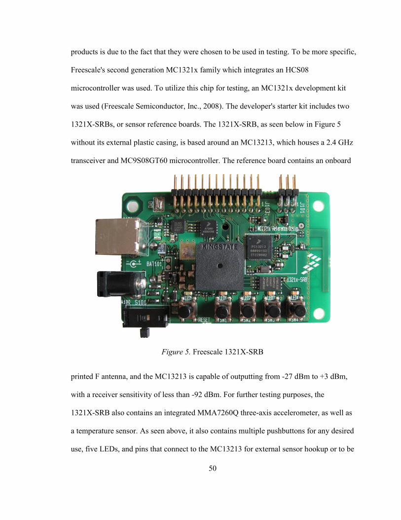
50
products is due to the fact that they were chosen to be used in testing. To be more specific,
Freescale's second generation MC1321x family which integrates an HCS08
microcontroller was used. To utilize this chip for testing, an MC1321x development kit
was used (Freescale Semiconductor, Inc., 2008). The developer's starter kit includes two
1321X-SRBs, or sensor reference boards. The 1321X-SRB, as seen below in Figure 5
without its external plastic casing, is based around an MC13213, which houses a 2.4 GHz
transceiver and MC9S08GT60 microcontroller. The reference board contains an onboard
Figure 5. Freescale 1321X-SRB
printed F antenna, and the MC13213 is capable of outputting from -27 dBm to +3 dBm,
with a receiver sensitivity of less than -92 dBm. For further testing purposes, the
1321X-SRB also contains an integrated MMA7260Q three-axis accelerometer, as well as
a temperature sensor. As seen above, it also contains multiple pushbuttons for any desired
use, five LEDs, and pins that connect to the MC13213 for external sensor hookup or to be
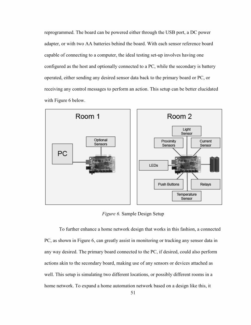
51
reprogrammed. The board can be powered either through the USB port, a DC power
adapter, or with two AA batteries behind the board. With each sensor reference board
capable of connecting to a computer, the ideal testing set-up involves having one
configured as the host and optionally connected to a PC, while the secondary is battery
operated, either sending any desired sensor data back to the primary board or PC, or
receiving any control messages to perform an action. This setup can be better elucidated
with Figure 6 below.
Figure 6. Sample Design Setup
To further enhance a home network design that works in this fashion, a connected
PC, as shown in Figure 6, can greatly assist in monitoring or tracking any sensor data in
any way desired. The primary board connected to the PC, if desired, could also perform
actions akin to the secondary board, making use of any sensors or devices attached as
well. This setup is simulating two different locations, or possibly different rooms in a
home network. To expand a home automation network based on a design like this, it
52
would be necessary to duplicate the secondary room's system to as many rooms exist in a
household. Not shown however, is that an A/C could optionally be controlled as well. It
would however be much more appropriate to design an individual ZigBee based
thermostat with a display for that purpose. A lot more types of devices and monitoring
sensors can be used to make an even more complex home automated network. Despite
the current systems' relative simplicity, a lot can possibly be done based on how
resourceful one is with the data that can be collected.
To illustrate, two proximity sensors which can be very inexpensive, placed in
each rooms entry can detect if a person enters or leaves the room, based on which sensor
picks up the response first. If the data is stored, it would be possible to tell if there is
anybody in the room, how many people are in the room, which room is housing people,
and how many people are in the house. The light sensor in each room will then provide
the lighting conditions so the system knows how bright it is in each room. Using just
these two types of sensors so far, it would be possible to output to relays to turn on and
off lighting in whatever room people are in. If it is daytime and bright already, the light
may not even need to be on depending on whether people are in the room or not. Using a
slightly more complex system instead of relays, it would be possible to adjust dimmable
lighting to always try and achieve a certain brightness as measured by the light sensor.
These few features pointed out will already conserve a lot of power in a home,
controlling lighting so that lights are not draining energy when nobody is in the room, or
if they aren't needed. Using push buttons or ZigBee enabled wall switches, manual
control could always be added, optionally overriding certain automations. Using a
temperature sensor, even more information can be collected. It would be possible to
53
gather the temperature of each room, and if controlling an A/C unit, signaling when it
should be run. The A/C could optionally be controlled by choosing which room's
temperature to use. The last and important sensor resides in monitoring power use. By
using a current sensor, it is possible to monitor the current draw that the loads or lighting
in each room is using. Utilizing all the features mentioned, the system can track and
monitor the energy consumption for each individual room or as a whole, know the
individual temperature of each room and control an A/C based on them, know how bright
each room is, and whether or not anybody is in the room. Connecting the system to a PC
using suitable software, it would be easily possible to track the monitored data and
control the network. Convenience would obviously be a big addition, and it could give
the user all the collected data including energy use. By collecting the energy use from
each room individually, it would be possible to tell what or who is eating up the most
energy and help determine which areas can be improved on. Using the estimated price of
energy, it would also be helpful to calculate the expected cost for the week, month, or
year. Optionally, monitoring energy usage based on time of day may be of use. After
testing a design using sensors as described above, it was shown that a home network can
indeed be of great use, and that a ZigBee device would indeed work well, however some
design strategies could easily use modifications.
Hardware Design and Testing
Two Freescale 1321X-SRBs were used in testing as mentioned. It should be
pointed out that because of this, one of the main features one would use ZigBee was not
present. The network configurations or topologies that a ZigBee network can make use of
could not be used or tested. Using two devices like this, it is not really even a Star
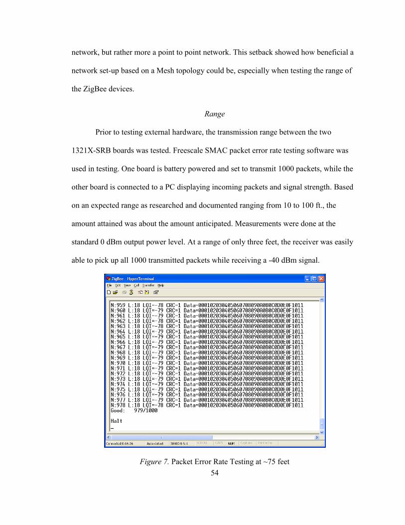
54
network, but rather more a point to point network. This setback showed how beneficial a
network set-up based on a Mesh topology could be, especially when testing the range of
the ZigBee devices.
Range
Prior to testing external hardware, the transmission range between the two
1321X-SRB boards was tested. Freescale SMAC packet error rate testing software was
used in testing. One board is battery powered and set to transmit 1000 packets, while the
other board is connected to a PC displaying incoming packets and signal strength. Based
on an expected range as researched and documented ranging from 10 to 100 ft., the
amount attained was about the amount anticipated. Measurements were done at the
standard 0 dBm output power level. At a range of only three feet, the receiver was easily
able to pick up all 1000 transmitted packets while receiving a -40 dBm signal.
Figure 7. Packet Error Rate Testing at ~75 feet
55
Increasing range to about twenty feet and placing the transmitter in another room, the
receiver was still able to pick up all 1000 transmitted packets, though the signal strength
dropped to about -70 dBm. As shown in Figure 7, it was not until the transmitter and
receiver were placed at opposite corners of the home were packets being lost. This
occurred at roughly -80 dBm, where 21 of the 1000 transmitted packets were never
picked up by the receiver. The home is a relatively open-spaced house, with the signal
having travel through about two standard drywall-based walls. If a network with just one
more ZigBee device were in place, the whole home could possibly be spanned by the
networks range. A typical ZigBee network can easily include several devices across a
home, with possibly several different types of devices including a ZigBee transceiver. If
designed properly, with many of the nodes configured as routers to relay data, range will
very clearly be the last concern one should have. Furthermore, as mentioned already,
range extenders could also be used as a last resort should they be needed. Simply
plugging in a range extender into a wall outlet, range will never be an issue.
Proximity Sensing
Several different implementations of proximity sensors were tested for use. The
first being a simple custom comparator op-amp based design using an infrared LED and
matching infrared transistor. This implementation did not provide nearly enough sensing
distance to be a good candidate at detecting people passing by, only detecting objects
within ten inches. Other prebuilt solutions by Sharp Microelectronics were then used,
with both digital and analog formats tested. The only method to provide enough sensing
distance was the use of 80 cm GP2Y0A21YK0F and 150 cm GP2Y0A02YK0F analog
sensors. Using analog sensors however, it is necessary to implement them in a

56
comparator design to provide logic highs and lows. Figure 8 shows how the final design
is implemented for the two proximity sensors. It should be noted that two separate
Figure 8. Proximity Sensor Diagram
implementations of the above diagram are required with the need for two separate sensors.
An LM311 comparator chip compares the proximity sensor's analog output voltage with
an adjustable voltage that can be tweaked via a potentiometer. The circuitry after the
comparator is somewhat optional however. After a pull-up resistor, a logic high 5 V and
low 0 V is provided. The 1321X-SRB operates at a maximum of 3.4 V however. Using a
rail-to-rail op-amp following the logic signal, it will be possible to adjust the voltage
amplitude. On the other hand, because the input pins of the microcontroller being used
for the proximity sensors are simultaneously being used by pushbuttons, a relay is
connected after the op-amp as well to short the input and simulate a pushbutton. By
implementing the proximity sensors this way, the pushbuttons can simulate the sensors
for testing purposes. Overall, the proximity sensors worked as desired. The
GP2Y0A02YK0F in particular was easily able to detect objects at over one meter away,
and if any calibration was needed, the potentiometers easily adjusted the sensor's
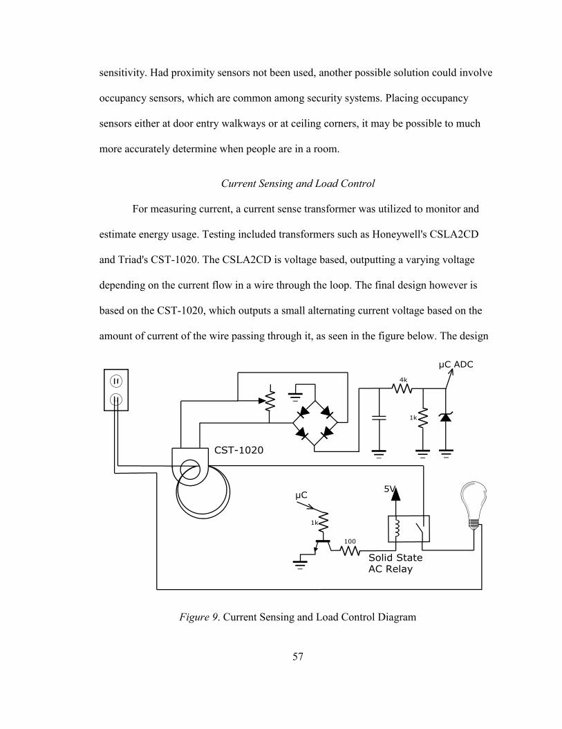
57
sensitivity. Had proximity sensors not been used, another possible solution could involve
occupancy sensors, which are common among security systems. Placing occupancy
sensors either at door entry walkways or at ceiling corners, it may be possible to much
more accurately determine when people are in a room.
Current Sensing and Load Control
For measuring current, a current sense transformer was utilized to monitor and
estimate energy usage. Testing included transformers such as Honeywell's CSLA2CD
and Triad's CST-1020. The CSLA2CD is voltage based, outputting a varying voltage
depending on the current flow in a wire through the loop. The final design however is
based on the CST-1020, which outputs a small alternating current voltage based on the
amount of current of the wire passing through it, as seen in the figure below. The design
Figure 9. Current Sensing and Load Control Diagram
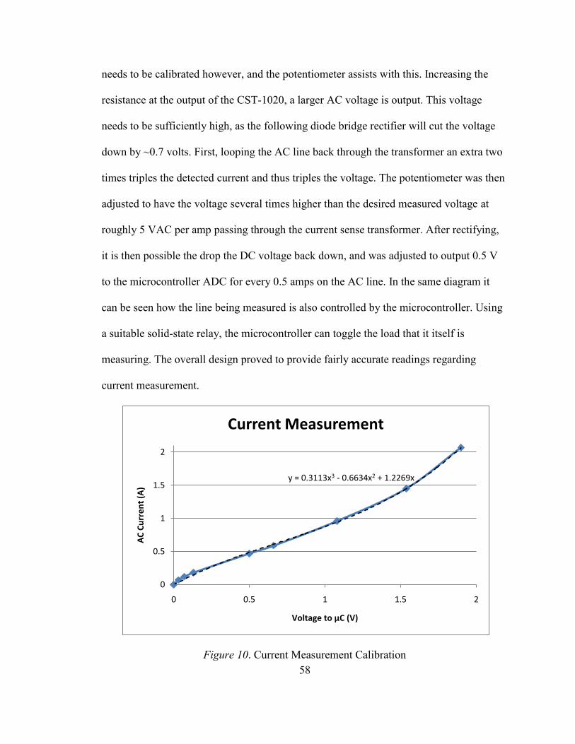
58
needs to be calibrated however, and the potentiometer assists with this. Increasing the
resistance at the output of the CST-1020, a larger AC voltage is output. This voltage
needs to be sufficiently high, as the following diode bridge rectifier will cut the voltage
down by ~0.7 volts. First, looping the AC line back through the transformer an extra two
times triples the detected current and thus triples the voltage. The potentiometer was then
adjusted to have the voltage several times higher than the desired measured voltage at
roughly 5 VAC per amp passing through the current sense transformer. After rectifying,
it is then possible the drop the DC voltage back down, and was adjusted to output 0.5 V
to the microcontroller ADC for every 0.5 amps on the AC line. In the same diagram it
can be seen how the line being measured is also controlled by the microcontroller. Using
a suitable solid-state relay, the microcontroller can toggle the load that it itself is
measuring. The overall design proved to provide fairly accurate readings regarding
current measurement.
Figure 10. Current Measurement Calibration
y = 0.3113x3 - 0.6634x2 + 1.2269x
0
0.5
1
1.5
2
0 0.5 1 1.5 2
AC
Cu
rre
nt
(A)
Voltage to µC (V)
Current Measurement
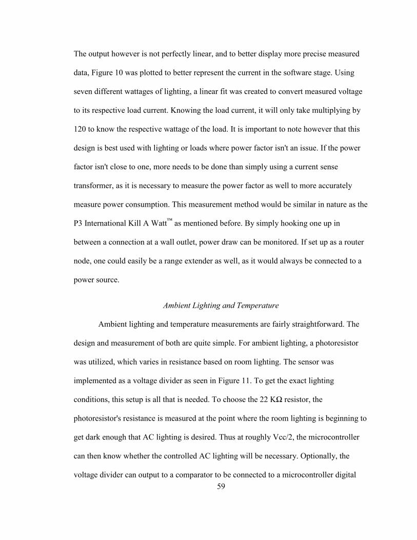
59
The output however is not perfectly linear, and to better display more precise measured
data, Figure 10 was plotted to better represent the current in the software stage. Using
seven different wattages of lighting, a linear fit was created to convert measured voltage
to its respective load current. Knowing the load current, it will only take multiplying by
120 to know the respective wattage of the load. It is important to note however that this
design is best used with lighting or loads where power factor isn't an issue. If the power
factor isn't close to one, more needs to be done than simply using a current sense
transformer, as it is necessary to measure the power factor as well to more accurately
measure power consumption. This measurement method would be similar in nature as the
P3 International Kill A Watt™
as mentioned before. By simply hooking one up in
between a connection at a wall outlet, power draw can be monitored. If set up as a router
node, one could easily be a range extender as well, as it would always be connected to a
power source.
Ambient Lighting and Temperature
Ambient lighting and temperature measurements are fairly straightforward. The
design and measurement of both are quite simple. For ambient lighting, a photoresistor
was utilized, which varies in resistance based on room lighting. The sensor was
implemented as a voltage divider as seen in Figure 11. To get the exact lighting
conditions, this setup is all that is needed. To choose the 22 KΩ resistor, the
photoresistor's resistance is measured at the point where the room lighting is beginning to
get dark enough that AC lighting is desired. Thus at roughly Vcc/2, the microcontroller
can then know whether the controlled AC lighting will be necessary. Optionally, the
voltage divider can output to a comparator to be connected to a microcontroller digital
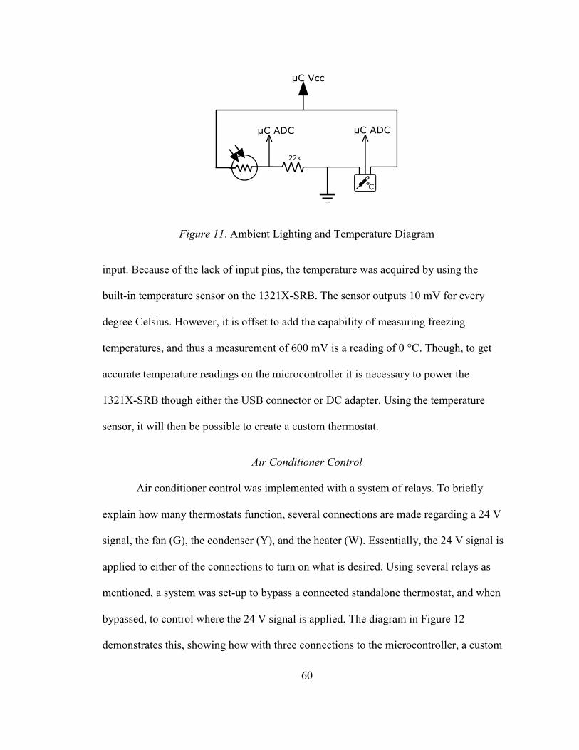
60
Figure 11. Ambient Lighting and Temperature Diagram
input. Because of the lack of input pins, the temperature was acquired by using the
built-in temperature sensor on the 1321X-SRB. The sensor outputs 10 mV for every
degree Celsius. However, it is offset to add the capability of measuring freezing
temperatures, and thus a measurement of 600 mV is a reading of 0 °C. Though, to get
accurate temperature readings on the microcontroller it is necessary to power the
1321X-SRB though either the USB connector or DC adapter. Using the temperature
sensor, it will then be possible to create a custom thermostat.
Air Conditioner Control
Air conditioner control was implemented with a system of relays. To briefly
explain how many thermostats function, several connections are made regarding a 24 V
signal, the fan (G), the condenser (Y), and the heater (W). Essentially, the 24 V signal is
applied to either of the connections to turn on what is desired. Using several relays as
mentioned, a system was set-up to bypass a connected standalone thermostat, and when
bypassed, to control where the 24 V signal is applied. The diagram in Figure 12
demonstrates this, showing how with three connections to the microcontroller, a custom
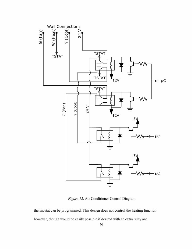
61
Figure 12. Air Conditioner Control Diagram
thermostat can be programmed. This design does not control the heating function
however, though would be easily possible if desired with an extra relay and
62
microcontroller connection akin to cooling. In the above diagram, the TSTAT
connections go to the standalone thermostat's respective 24 V, Y, W, and G terminals. In
this fashion, with no signal from the microcontroller, the setup acts as if nothing is
changed and the standalone thermostat is controlling the air conditioner normally. The
first microcontroller signal is used by bypass the thermostat, having the wall connections
disconnected from the thermostat. Only if the microcontroller bypasses the thermostat do
the second two relays have any effect, which are used to apply 24 V to either the
condenser or fan. It is important to note that the condenser should not be toggled back on
too rapidly and there is no safety for this aside from the software control. It is necessary
to design the software in such a way that will prevent the microcontroller from turning
the condenser off and on too quickly when the thermostat is bypassed. With all of the
hardware functioning as desired, it is possible to create the software that will utilize all
the designs mentioned.
Software Design
The software design using two Freescale 1321X-SRB's involves creating three
separate programs that communicate with each other in one way or another. Two of the
programs are for each of the 1321X-SRB's, as each will be performing different tasks and
communicating differently, while the third is a PC application that will communicate
with the microcontroller connected to the PC. For the design mentioned beforehand, the
1321X-SRB connected to the PC is in a way the middle-man between the PC and remote
microcontroller board. The primary purpose of the remote microcontroller is to gather
sensor data and control lighting and air conditioning, while the PC application will be
capable of displaying data collected by the remote board, while adding the functionality
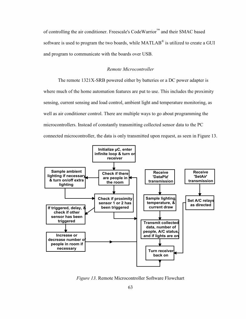
63
of controlling the air conditioner. Freescale's CodeWarrior™
and their SMAC based
software is used to program the two boards, while MATLAB®
is utilized to create a GUI
and program to communicate with the boards over USB.
Remote Microcontroller
The remote 1321X-SRB powered either by batteries or a DC power adapter is
where much of the home automation features are put to use. This includes the proximity
sensing, current sensing and load control, ambient light and temperature monitoring, as
well as air conditioner control. There are multiple ways to go about programming the
microcontrollers. Instead of constantly transmitting collected sensor data to the PC
connected microcontroller, the data is only transmitted upon request, as seen in Figure 13.
Figure 13. Remote Microcontroller Software Flowchart
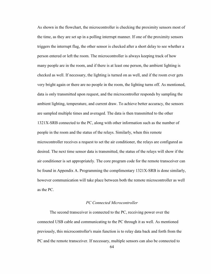
64
As shown in the flowchart, the microcontroller is checking the proximity sensors most of
the time, as they are set up in a polling interrupt manner. If one of the proximity sensors
triggers the interrupt flag, the other sensor is checked after a short delay to see whether a
person entered or left the room. The microcontroller is always keeping track of how
many people are in the room, and if there is at least one person, the ambient lighting is
checked as well. If necessary, the lighting is turned on as well, and if the room ever gets
very bright again or there are no people in the room, the lighting turns off. As mentioned,
data is only transmitted upon request, and the microcontroller responds by sampling the
ambient lighting, temperature, and current draw. To achieve better accuracy, the sensors
are sampled multiple times and averaged. The data is then transmitted to the other
1321X-SRB connected to the PC, along with other information such as the number of
people in the room and the status of the relays. Similarly, when this remote
microcontroller receives a request to set the air conditioner, the relays are configured as
desired. The next time sensor data is transmitted, the status of the relays will show if the
air conditioner is set appropriately. The core program code for the remote transceiver can
be found in Appendix A. Programming the complimentary 1321X-SRB is done similarly,
however communication will take place between both the remote microcontroller as well
as the PC.
PC Connected Microcontroller
The second transceiver is connected to the PC, receiving power over the
connected USB cable and communicating to the PC through it as well. As mentioned
previously, this microcontroller's main function is to relay data back and forth from the
PC and the remote transceiver. If necessary, multiple sensors can also be connected to
65
this board as well. The program functions similarly to the remote microcontroller's,
however instead of awaiting a signal over the air, the program checks to see if there was
any incoming string from the PC, as shown in the flowchart below. As can be seen, the
Figure 14. PC Connected Microcontroller Software Flowchart
program acts depending on what the PC transmits. There are six possible character strings
the microcontroller checks for from the PC. Receiving a 'D,' the microcontroller follows
by asking the remote microcontroller for the sensor, relay, and other data. The receiver is
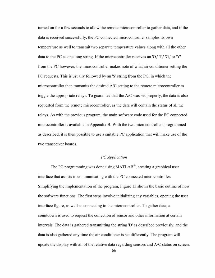
66
turned on for a few seconds to allow the remote microcontroller to gather data, and if the
data is received successfully, the PC connected microcontroller samples its own
temperature as well to transmit two separate temperature values along with all the other
data to the PC as one long string. If the microcontroller receives an 'O,' 'T,' 'G,' or 'Y'
from the PC however, the microcontroller makes note of what air conditioner setting the
PC requests. This is usually followed by an 'S' string from the PC, in which the
microcontroller then transmits the desired A/C setting to the remote microcontroller to
toggle the appropriate relays. To guarantee that the A/C was set properly, the data is also
requested from the remote microcontroller, as the data will contain the status of all the
relays. As with the previous program, the main software code used for the PC connected
microcontroller is available in Appendix B. With the two microcontrollers programmed
as described, it is then possible to use a suitable PC application that will make use of the
two transceiver boards.
PC Application
The PC programming was done using MATLAB®, creating a graphical user
interface that assists in communicating with the PC connected microcontroller.
Simplifying the implementation of the program, Figure 15 shows the basic outline of how
the software functions. The first steps involve initializing any variables, opening the user
interface figure, as well as connecting to the microcontroller. To gather data, a
countdown is used to request the collection of sensor and other information at certain
intervals. The data is gathered transmitting the string 'D' as described previously, and the
data is also gathered any time the air conditioner is set differently. The program will
update the display with all of the relative data regarding sensors and A/C status on screen.
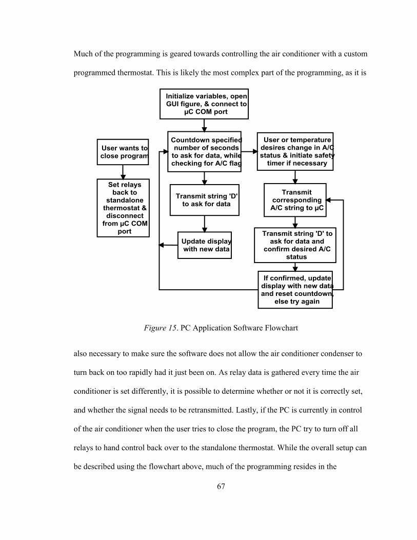
67
Much of the programming is geared towards controlling the air conditioner with a custom
programmed thermostat. This is likely the most complex part of the programming, as it is
Figure 15. PC Application Software Flowchart
also necessary to make sure the software does not allow the air conditioner condenser to
turn back on too rapidly had it just been on. As relay data is gathered every time the air
conditioner is set differently, it is possible to determine whether or not it is correctly set,
and whether the signal needs to be retransmitted. Lastly, if the PC is currently in control
of the air conditioner when the user tries to close the program, the PC try to turn off all
relays to hand control back over to the standalone thermostat. While the overall setup can
be described using the flowchart above, much of the programming resides in the
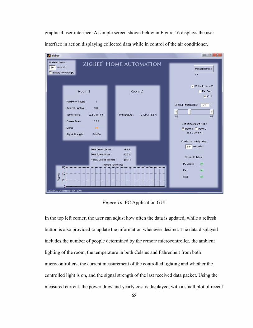
68
graphical user interface. A sample screen shown below in Figure 16 displays the user
interface in action displaying collected data while in control of the air conditioner.
Figure 16. PC Application GUI
In the top left corner, the user can adjust how often the data is updated, while a refresh
button is also provided to update the information whenever desired. The data displayed
includes the number of people determined by the remote microcontroller, the ambient
lighting of the room, the temperature in both Celsius and Fahrenheit from both
microcontrollers, the current measurement of the controlled lighting and whether the
controlled light is on, and the signal strength of the last received data packet. Using the
measured current, the power draw and yearly cost is displayed, with a small plot of recent
69
wattage measurements. It can be seen how the current sense transformer design is
correctly measuring a 60 watt light that is being controlled. The right hand side of the
GUI is primarily dedicated to the custom thermostat. After enabling PC Control of the
thermostat, it is then possible to configure the air conditioner in fan only or cool mode. It
is possible to select a desired temperature that the PC will try to maintain turning on and
off the air conditioner as necessary. As the gathered data includes two temperature
readings from different rooms, either one can be selected for the control to be based on.
For testing purposes, the condenser safety delay can be edited, which like the update
interval, is a timer that counts down a certain number of seconds before the condenser
can be turned back on. Along with the other collected data, the status of the air
conditioner thermostat, fan, and cooling relays is also displayed. The MATLAB® m file
code for this GUI application can be found in Appendix C.
70
VI. FINAL THOUGHTS
Based on experimentation and research, ZigBee proved to be a very capable
wireless networking standard. Whether from its ease-of-use, to its possible networking
features, to its transmission characteristics, many applications would greatly benefit from
the use of this wireless sensing and control standard. The possibilities are almost endless
in what can be done with a wireless network like ZigBee. ZigBee's ease-of-use relates to
both manufacturers and end-users. Applications are relatively easy to develop for, while
as a product ZigBee's networking requires hardly any set-up. Application profiles made
available by the ZigBee Alliance further assist by making ZigBee products interoperable
between different vendors. Long battery-life and low power use with the 802.15.4 are
also prominent features. Range, while not its greatest quality, is not an issue with the
network topology and node types available. The multitude of frequency channels
available further add to the robustness of a ZigBee network. Data rate is relatively slow
using ZigBee, especially in comparison to other networking standards available, but as
has been said, for the purposes of control and monitoring this is of very little concern.
Aside from home automation, some areas of interest in which ZigBee may prove to
become quite popular include ZigBee RF4CE and ZigBee Smart Energy. With RF4CE,
the ZigBee standard can be of great use in the consumer electronics market. Infrared
remote controls have been around for a long time, and there is much room for innovation.
Regarding ZigBee Smart Energy, its purposes are relatively similar to the goals desired in
71
the sample design experiment, though leans more towards monitoring energy use and
interconnecting with your utility service. It may be possible to incorporate ZigBee
products that provide these energy purposes into a more sophisticated automated network,
as considered for the sample design. A "smart home automation network" like this could
then assist with all the control, convenience, and security of a home automation network,
with a strong emphasis in conservation. Simply knowing how much energy is used and
its cost helps consumers conserve. Regardless of its application, the use of ZigBee
provides a low-cost, efficient, flexible, and robust means to create any desired wireless
sensing and control network.
The sample designs tested and experimented on showed how ZigBee transceivers
provide a very effective means of wireless communication for home automation. While
only two transceivers were used, they provided a good insight as to how a large-scale
ZigBee network could be implemented. The multiple hardware and software designs
proved to work well for use in home automation and assist in power conservation.
Proximity sensors and ambient lighting measurements effectively assisted in controlling
automatic lighting, while monitoring current accurately depicted the lighting’s power
usage. Air conditioner control also worked just as desired, easily and safely coexisting
with a preinstalled thermostat. On the whole, the sample design experiment proved to
show how ZigBee is a very practical networking standard for use in home automation or
other sensor and control networks.
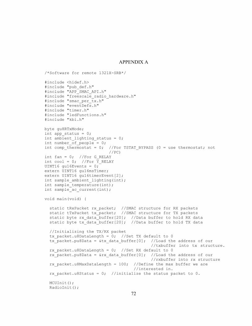
72
APPENDIX A
/*Software for remote 1321X-SRB*/
#include <hidef.h>
#include "pub_def.h"
#include "APP_SMAC_API.h"
#include "freescale_radio_hardware.h"
#include "smac_per_tx.h"
#include "eventDefs.h"
#include "timer.h"
#include "ledFunctions.h"
#include "kbi.h"
byte gu8RTxMode;
int app_status = 0;
int ambient_lighting_status = 0;
int number_of_people = 0;
int comp_thermostat = 0; //For TSTAT_BYPASS (0 = use thermostat; not
//PC)
int fan = 0; //For G_RELAY
int cool = 0; //For Y_RELAY
UINT16 gu16Events = 0;
extern UINT16 gu16msTimer;
extern UINT16 gu16timerEvent[2];
int sample_ambient_lighting(int);
int sample_temperature(int);
int sample_ac_current(int);
void main(void)
static tRxPacket rx_packet; //SMAC structure for RX packets
static tTxPacket tx_packet; //SMAC structure for TX packets
static byte rx_data_buffer[20]; //Data buffer to hold RX data
static byte tx_data_buffer[20]; //Data buffer to hold TX data
//Initializing the TX/RX packet
tx_packet.u8DataLength = 0; //Set TX default to 0
tx_packet.pu8Data = &tx_data_buffer[0]; //Load the address of our
//txbuffer into tx structure.
rx_packet.u8DataLength = 0; //Set RX default to 0
rx_packet.pu8Data = &rx_data_buffer[0]; //Load the address of our
//rxbuffer into rx structure
rx_packet.u8MaxDataLength = 100; //Define the max buffer we are
//interested in.
rx_packet.u8Status = 0; //initialize the status packet to 0.
MCUInit();
RadioInit();
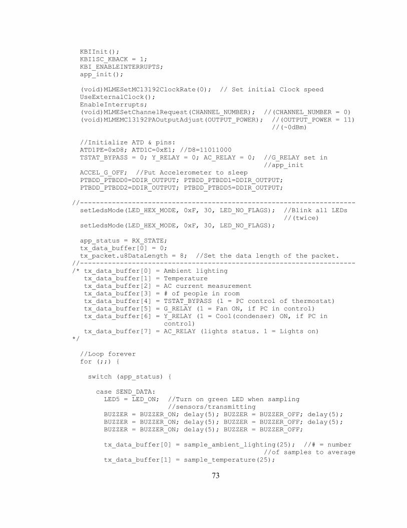
73
KBIInit();
KBI1SC_KBACK = 1;
KBI_ENABLEINTERRUPTS;
app_init();
(void)MLMESetMC13192ClockRate(0); // Set initial Clock speed
UseExternalClock();
EnableInterrupts;
(void)MLMESetChannelRequest(CHANNEL_NUMBER); //(CHANNEL_NUMBER = 0)
(void)MLMEMC13192PAOutputAdjust(OUTPUT_POWER); //(OUTPUT_POWER = 11)
//(~0dBm)
//Initialize ATD & pins:
ATD1PE=0xD8; ATD1C=0xE1; //D8=11011000
TSTAT_BYPASS = 0; Y_RELAY = 0; AC_RELAY = 0; //G_RELAY set in
//app_init
ACCEL_G_OFF; //Put Accelerometer to sleep
PTBDD_PTBDD0=DDIR_OUTPUT; PTBDD_PTBDD1=DDIR_OUTPUT;
PTBDD_PTBDD2=DDIR_OUTPUT; PTBDD_PTBDD5=DDIR_OUTPUT;
//---------------------------------------------------------------------
setLedsMode(LED_HEX_MODE, 0xF, 30, LED_NO_FLAGS); //Blink all LEDs
//(twice)
setLedsMode(LED_HEX_MODE, 0xF, 30, LED_NO_FLAGS);
app_status = RX_STATE;
tx_data_buffer[0] = 0;
tx_packet.u8DataLength = 8; //Set the data length of the packet.
//---------------------------------------------------------------------
/* tx_data_buffer[0] = Ambient lighting
tx_data_buffer[1] = Temperature
tx_data_buffer[2] = AC current measurement
tx_data_buffer[3] = # of people in room
tx_data_buffer[4] = TSTAT_BYPASS (1 = PC control of thermostat)
tx_data_buffer[5] = G_RELAY (1 = Fan ON, if PC in control)
tx_data_buffer[6] = Y_RELAY (1 = Cool(condenser) ON, if PC in
control)
tx_data_buffer[7] = AC_RELAY (lights status. 1 = Lights on)
*/
//Loop forever
for (;;)
switch (app_status)
case SEND_DATA:
LED5 = LED_ON; //Turn on green LED when sampling
//sensors/transmitting
BUZZER = BUZZER_ON; delay(5); BUZZER = BUZZER_OFF; delay(5);
BUZZER = BUZZER_ON; delay(5); BUZZER = BUZZER_OFF; delay(5);
BUZZER = BUZZER_ON; delay(5); BUZZER = BUZZER_OFF;
tx_data_buffer[0] = sample_ambient_lighting(25); //# = number
//of samples to average
tx_data_buffer[1] = sample_temperature(25);
74
tx_data_buffer[2] = sample_ac_current(25);
tx_data_buffer[3] = number_of_people;
tx_data_buffer[4] = TSTAT_BYPASS;
tx_data_buffer[5] = G_RELAY;
tx_data_buffer[6] = Y_RELAY;
tx_data_buffer[7] = AC_RELAY;
if (MCPSDataRequest(&tx_packet) == SUCCESS) //Transmit
LED1 ^= 1;
LED5 = LED_OFF;
app_status = RX_STATE;
break;
case SET_AIR:
TSTAT_BYPASS = comp_thermostat;
G_RELAY = fan;
Y_RELAY = cool;
app_status = RX_STATE;
break;
case RX_STATE:
MLMERXEnableRequest(&rx_packet,0); //Keep receiver on
app_status = IDLE_STATE;
break;
case IDLE_STATE:
break;
//end of app_status switch class
if (number_of_people > 0) //Turn on AC light if necessary
ambient_lighting_status = sample_ambient_lighting(25);
if (ambient_lighting_status < 170)
AC_RELAY = 1;
else if (ambient_lighting_status > 200)
AC_RELAY = 0;
else
AC_RELAY = 0; //Always have light off if no people regardless of
//lighting
//---------------------------------------------------------------------
//Check for debounce timer (TIMER1)
if ((gu16Events & TIMER_EVENT1) != 0)
gu16Events &= ~TIMER_EVENT1; //Clear the event
gu16timerEvent[1] = 0; //Turn off the timer
//(If PROX1 is triggered) (or SW3)
if ((gu16Events & KBI4_EVENT) != 0)
gu16Events &= ~KBI4_EVENT;
75
BUZZER = BUZZER_ON;
delay(10);
BUZZER = BUZZER_OFF;
delay(400); //Time to give PROX2 to be triggered to count a
//person entering
if ((gu16Events & KBI3_EVENT) != 0) //If PROX2 triggered
gu16Events &= ~KBI3_EVENT;
number_of_people++;
//(If PROX2 is triggered) (or SW2)
if ((gu16Events & KBI3_EVENT) != 0)
gu16Events &= ~KBI3_EVENT;
BUZZER = BUZZER_ON;
delay(10);
BUZZER = BUZZER_OFF;
delay(400); //Time to give PROX1 to be triggered to count a
//person leaving
if ((gu16Events & KBI4_EVENT) != 0)
gu16Events &= ~KBI4_EVENT;
if (number_of_people > 0)
number_of_people--;
//(If SW1 is pressed)
if ((gu16Events & KBI2_EVENT) != 0)
BUZZER = BUZZER_ON;
delay(20);
BUZZER = BUZZER_OFF;
gu16Events &= ~KBI2_EVENT;
app_status = SEND_DATA;
//end of infinite for loop
//end of main
//--------------------------------------------------------------------
void MCPSDataIndication(tRxPacket *rx_packet)
if (rx_packet->u8Status == TIMEOUT)
76
app_status = RX_STATE;
if (rx_packet->u8Status == SUCCESS) //Good packet received.
if (rx_packet->pu8Data[0] == 'D' &&
rx_packet->pu8Data[1] == 'a' &&
rx_packet->pu8Data[2] == 't' &&
rx_packet->pu8Data[3] == 'a' &&
rx_packet->pu8Data[4] == 'P' &&
rx_packet->pu8Data[5] == 'l' &&
rx_packet->pu8Data[6] == 'z')
app_status = SEND_DATA;
else if (rx_packet->pu8Data[0] == 'S' &&
rx_packet->pu8Data[1] == 'e' &&
rx_packet->pu8Data[2] == 't' &&
rx_packet->pu8Data[3] == 'A' &&
rx_packet->pu8Data[4] == 'i' &&
rx_packet->pu8Data[5] == 'r')
comp_thermostat = rx_packet->pu8Data[6];
fan = rx_packet->pu8Data[7];
cool = rx_packet->pu8Data[8];
app_status = SET_AIR;
else
app_status = RX_STATE;
//end MCPSDataIndication()
void MLMEMC13192ResetIndication()
RadioInit();
app_status = IDLE_STATE;
void app_init()
LED_INIT_MACRO; //Set LEDs off & initialize as outputs
BUZZER_INIT_MACRO; //Set Buzzer off & initialize as output
//Set Push button pull ups (SW1,SW2,SW3). Note: SW2 used for PROX2 &
//SW3 used for PROX1; SW4 port (as output) used for G_RELAY
PB0PU = 1; PB1PU = 1; PB2PU = 1;
G_RELAY=0; PTADD_PTADD5 = 1;
//Setup Timer 1
TPM1MOD = 625; //Set the timer for a 26ms timer rate (1/8E6) * 128 *
77
//625 = 10msec
//Timer rate = (1/BUSCLOCK) * TIMER_PRESCALER * TIMER MOD
TPM1SC = 0x4F; //Timer divide by 128. (16uS timebase for 8MHz bus
//clock). interrupt on
int sample_ambient_lighting(int samples)
int average = 0;
int i;
for(i=1; i<=samples; i++)
AMBIENT_LIGHT; //Sample AMBIENT_LIGHT voltage (for new binary
//voltage to read)
while((ATD1SC & 0x80) != 0x80);
average = average + ATD1RH; //Read & add conversion data to
//'average'
delay(3);
average = average/samples;
return average;
int sample_temperature(int samples)
int average = 0;
int i;
for(i=1; i<=samples; i++)
TEMP_VOUT;
while((ATD1SC & 0x80) != 0x80);
average = average + ATD1RH;
delay(3);
average = average/samples;
return average;
int sample_ac_current(int samples)
int average = 0;
int i;
for(i=1; i<=samples; i++)
CURRENT_MEAS;
while((ATD1SC & 0x80) != 0x80);
average = average + ATD1RH;
delay(20);
average = average/samples;
return average;
78
APPENDIX B
/*Software for 1321X-SRB connected to PC*/
#include <hidef.h>
#include "pub_def.h"
#include "LCD.h"
#include "SCI.h"
#include "APP_SMAC_API.h"
#include "freescale_radio_hardware.h"
#include "smac_per_rx.h"
#include "eventDefs.h"
#include "timer.h"
#include "ledFunctions.h"
#include <string.h>
#include "kbi.h"
#include "ascii_utilities.h"
byte gu8RTxMode;
int app_status = 0;
int ambient_lighting_status = 0;
int temperature = 0;
int pc_temperature = 0;
int ac_current = 0;
int number_of_people = 0;
int tstat_bypass_status = 0;
int g_relay_status = 0;
int y_relay_status = 0;
int lights_status = 0;
int comp_thermostat = 0; //For TSTAT_BYPASS (0 = use thermostat; not
//PC)
int fan = 0; //For G_RELAY
int cool = 0; //For Y_RELAY
UINT8 link_quality;
extern UINT8 gu8SCIData[128];
extern UINT8 gu8SCIDataFlag;
UINT16 gu16Events = 0;
extern UINT16 gu16msTimer;
extern UINT16 gu16timerEvent[2];
void main(void)
static tRxPacket rx_packet; //SMAC structure for RX packets
static tTxPacket tx_packet; //SMAC structure for TX packets
static byte rx_data_buffer[20]; //Data buffer to hold RX data, if
//you want larger packets change 20 to what you need.
static byte tx_data_buffer[20]; //Data buffer to hold TX data, if
//you want larger packets change 20 to what you need.
79
char App_String[10]; //To store string transmitted over USB
//Initialize the TX/RX packet
tx_packet.u8DataLength = 0; //Set TX default length to 0
tx_packet.pu8Data = &tx_data_buffer[0]; //Load the address of our
//txbuffer into the tx structure
rx_packet.u8DataLength = 0; //Set RX default length to 0
rx_packet.pu8Data = &rx_data_buffer[0]; //Load the address of our
//rxbuffer into the rx structure
rx_packet.u8MaxDataLength = 128; //Define the max buffer we
//are interested in.
rx_packet.u8Status = 0; //initial status variable for rx to 0.
MCUInit();
RadioInit();
app_init();
SCIInitGeneric(8000000, 38400, DEFAULT_SCI_PORT);
KBIInit();
KBI_ENABLEINTERRUPTS;
(void)MLMESetMC13192ClockRate(0); //Set initial Clock speed
UseExternalClock();
EnableInterrupts;
(void)MLMESetChannelRequest(CHANNEL_NUMBER); //(CHANNEL_NUMBER = 0)
(void)MLMEMC13192PAOutputAdjust(OUTPUT_POWER); //(OUTPUT_POWER = 11)
//(~0dBm)
//Initialize ATD for temperature:
ATD1PE = 0xC0; ATD1C = 0xE1; //C0=11000000
setLedsMode(LED_HEX_MODE, 0xF, 30, LED_NO_FLAGS); //Blink all LEDs
//(twice)
setLedsMode(LED_HEX_MODE, 0xF, 30, LED_NO_FLAGS);
app_status = IDLE_STATE;
//---------------------------------------------------------------------
//Loop forever
for (;;)
switch (app_status)
case ASK_FOR_DATA:
LED5 = LED_ON;
tx_data_buffer[0] = 'D';
tx_data_buffer[1] = 'a';
tx_data_buffer[2] = 't';
tx_data_buffer[3] = 'a';
tx_data_buffer[4] = 'P';
tx_data_buffer[5] = 'l';
tx_data_buffer[6] = 'z';
tx_packet.u8DataLength = 7;
if (MCPSDataRequest(&tx_packet) == SUCCESS)
LED2 ^= 1;
80
(void)MLMERXEnableRequest(&rx_packet,DELAY_COUNT);
//Temporarily turn on receiver
LED5 = LED_OFF;
app_status = IDLE_STATE;
break;
case SET_AIR_COND:
LED5 = LED_ON;
tx_data_buffer[0] = 'S';
tx_data_buffer[1] = 'e';
tx_data_buffer[2] = 't';
tx_data_buffer[3] = 'A';
tx_data_buffer[4] = 'i';
tx_data_buffer[5] = 'r';
tx_data_buffer[6] = comp_thermostat;
tx_data_buffer[7] = fan;
tx_data_buffer[8] = cool;
tx_packet.u8DataLength = 9;
if (MCPSDataRequest(&tx_packet) == SUCCESS)
LED2 ^= 1;
delay(250); //Give time to switch Air Cond and await a new
//request
LED5 = LED_OFF;
app_status = ASK_FOR_DATA; //To confirm that the air
//conditioner is as desired
break;
case IDLE_STATE:
break;
case GOOD_PACKET:
LED1 ^= 1;
//Note: Adding 1000 or 100 to have transferred data retain same
//string length (will later ignore first 1 in each case)
link_quality = (UINT8)(MLMELinkQuality()/2); //Signal strength
//of last received packet
ambient_lighting_status = rx_packet.pu8Data[0] + 1000;
temperature = rx_packet.pu8Data[1] + 1000; //Temp is 600mV
//offset
ac_current = rx_packet.pu8Data[2] + 1000;
number_of_people = rx_packet.pu8Data[3] + 100;
tstat_bypass_status = rx_packet.pu8Data[4]; //Relay status'
//will either be 0 or 1
g_relay_status = rx_packet.pu8Data[5];
y_relay_status = rx_packet.pu8Data[6];
lights_status = rx_packet.pu8Data[7];
//--------------------------------
//Sampling own temperature to give PC two different room
//temperatures
pc_temperature = sample_temperature(25) + 1000;
//--------------------------------
81
SCITransmitStr("LQI=-");
(void)int2string((UINT32) link_quality, App_String);
(void)trimWhiteSpace(App_String);
SCITransmitStr(App_String);
SCITransmitStr(" Ambient Lighting=");
(void)int2string((UINT32) ambient_lighting_status, App_String);
(void)trimWhiteSpace(App_String);
SCITransmitStr(App_String);
SCITransmitStr(" Temperature=");
(void)int2string((UINT32) temperature, App_String);
(void)trimWhiteSpace(App_String);
SCITransmitStr(App_String);
SCITransmitStr(" CurrentMeas=");
(void)int2string((UINT32) ac_current, App_String);
(void)trimWhiteSpace(App_String);
SCITransmitStr(App_String);
SCITransmitStr(" People=");
(void)int2string((UINT32) number_of_people, App_String);
(void)trimWhiteSpace(App_String);
SCITransmitStr(App_String);
SCITransmitStr(" Tstat_bypass=");
(void)int2string((UINT32) tstat_bypass_status, App_String);
(void)trimWhiteSpace(App_String);
SCITransmitStr(App_String);
SCITransmitStr(" G_Relay=");
(void)int2string((UINT32) g_relay_status, App_String);
(void)trimWhiteSpace(App_String);
SCITransmitStr(App_String);
SCITransmitStr(" Y_Relay=");
(void)int2string((UINT32) y_relay_status, App_String);
(void)trimWhiteSpace(App_String);
SCITransmitStr(App_String);
SCITransmitStr(" Lights=");
(void)int2string((UINT32) lights_status, App_String);
(void)trimWhiteSpace(App_String);
SCITransmitStr(App_String);
SCITransmitStr(" PC_Temperature=");
(void)int2string((UINT32) pc_temperature, App_String);
(void)trimWhiteSpace(App_String);
SCITransmitStr(App_String);
SCITransmitStr("\r\n");
app_status = IDLE_STATE;
break;
//end of app_status switch class
82
//---------------------------------------------------------------------
if (gu8SCIDataFlag == 1)
switch (gu8SCIData[0])
case 'D': //Computer asking for sensor data
BUZZER = BUZZER_ON; delay(5);
BUZZER = BUZZER_OFF; delay(5);
BUZZER = BUZZER_ON; delay(5);
BUZZER = BUZZER_OFF; delay(5);
BUZZER = BUZZER_ON; delay(5);
BUZZER = BUZZER_OFF;
app_status = ASK_FOR_DATA;
break;
case 'O':
comp_thermostat = 0;
fan = 0;
cool = 0;
app_status = IDLE_STATE;
break;
case 'T': //Toggle thermostat relay (though don't transmit
//until 'S')
comp_thermostat = 1;
fan = 0;
cool = 0;
app_status = IDLE_STATE;
break;
case 'G': //To toggle G_RELAY (fan) (don't transmit yet)
comp_thermostat = 1;
fan = 1;
cool = 0;
app_status = IDLE_STATE;
break;
case 'Y': //To toggle Y_RELAY (cool/condenser) (don't transmit
//yet)
comp_thermostat = 1;
fan = 1;
cool = 1;
app_status = IDLE_STATE;
break;
case 'S': //Set Air conditioner (after setting desired relay
//states)
BUZZER = BUZZER_ON; delay(5);
BUZZER = BUZZER_OFF; delay(5);
BUZZER = BUZZER_ON; delay(5);
BUZZER = BUZZER_OFF; delay(5);
BUZZER = BUZZER_ON; delay(5);
BUZZER = BUZZER_OFF;
83
app_status = SET_AIR_COND;
break;
gu8SCIDataFlag = 0;
//---------------------------------------------------------------------
//Check for debounce timer (TIMER1)
if ((gu16Events & TIMER_EVENT1) != 0)
gu16Events &= ~TIMER_EVENT1; //Clear the event
gu16timerEvent[1] = 0; //Turn off the timer
//(If SW1 is pressed)
if ((gu16Events & KBI2_EVENT) != 0)
BUZZER = BUZZER_ON;
delay(10);
BUZZER = BUZZER_OFF;
gu16Events &= ~KBI2_EVENT;
app_status = ASK_FOR_DATA;
//(If SW2 is pressed)
if ((gu16Events & KBI3_EVENT) != 0)
BUZZER = BUZZER_ON;
delay(10);
BUZZER = BUZZER_OFF;
gu16Events &= ~KBI3_EVENT;
comp_thermostat ^= 1;
app_status = SET_AIR_COND;
//(If SW3 is pressed)
if ((gu16Events & KBI4_EVENT) != 0)
BUZZER = BUZZER_ON;
delay(10);
BUZZER = BUZZER_OFF;
gu16Events &= ~KBI4_EVENT;
fan ^= 1;
app_status = SET_AIR_COND;
//(If SW4 is pressed)
if ((gu16Events & KBI5_EVENT) != 0)
BUZZER = BUZZER_ON;
delay(10);
BUZZER = BUZZER_OFF;
84
gu16Events &= ~KBI5_EVENT;
cool ^= 1;
app_status = SET_AIR_COND;
//end of infinite for loop
//end of main
//---------------------------------------------------------------------
void MCPSDataIndication(tRxPacket *rx_packet2)
if (rx_packet2->u8Status == TIMEOUT)
BUZZER = BUZZER_ON;
delay(10);
BUZZER = BUZZER_OFF;
delay(10);
BUZZER = BUZZER_ON;
delay(10);
BUZZER = BUZZER_OFF;
delay(10);
BUZZER = BUZZER_ON;
delay(10);
BUZZER = BUZZER_OFF;
app_status = IDLE_STATE;
if (rx_packet2->u8Status == SUCCESS)
if (rx_packet2->u8DataLength == 8) //Data length of packet. Can
//add more conditions
app_status = GOOD_PACKET;
else
app_status = IDLE_STATE;
else
app_status = IDLE_STATE;
//end MCPSDataIndication()
void MLMEMC13192ResetIndication()
RadioInit();
app_status = IDLE_STATE;
void app_init(void)
LED_INIT_MACRO; //Set LEDs off & initialize as outputs
BUZZER_INIT_MACRO; //Set Buzzer off & initialize as output
85
//Set Push button pull ups
PB0PU = 1; PB1PU = 1; PB2PU = 1; PB3PU = 1;
//Setup Timer 1
TPM1MOD = 625; //Set the timer for a 26ms timer rate (1/8E6) * 128 *
//625 = 10msec
//Timer rate = (1/BUSCLOCK) * TIMER_PRESCALER * TIMER MOD
TPM1SC = 0x4F; //Timer divide by 128. (16uS timebase for 8MHz bus
//clock). interrupt on
int sample_temperature(int samples)
int average = 0;
int i;
for(i=1; i<=samples; i++)
TEMP_VOUT;
while((ATD1SC & 0x80) != 0x80);
average = average + ATD1RH;
delay(3);
average = average/samples;
return average;
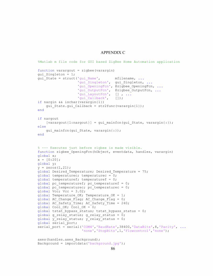
86
APPENDIX C
%Matlab m file code for GUI based ZigBee Home Automation application
function varargout = zigbee(varargin) gui_Singleton = 1; gui_State = struct('gui_Name', mfilename, ... 'gui_Singleton', gui_Singleton, ... 'gui_OpeningFcn', @zigbee_OpeningFcn, ... 'gui_OutputFcn', @zigbee_OutputFcn, ... 'gui_LayoutFcn', [] , ... 'gui_Callback', []); if nargin && ischar(varargin1) gui_State.gui_Callback = str2func(varargin1); end
if nargout [varargout1:nargout] = gui_mainfcn(gui_State, varargin:); else gui_mainfcn(gui_State, varargin:); end
% --- Executes just before zigbee is made visible. function zigbee_OpeningFcn(hObject, eventdata, handles, varargin) global x; x = [0:20]; global y; y = zeros(1,21); global Desired_Temperature; Desired_Temperature = 75; global temperaturec; temperaturec = 0; global temperaturef; temperaturef = 0; global pc_temperaturef; pc_temperaturef = 0; global pc_temperaturec; pc_temperaturec = 0; global Vcc; Vcc = 3.02; global Temperature_OK; Temperature_OK = 1; global AC_Change_Flag; AC_Change_Flag = 0; global AC_Safety_Time; AC_Safety_Time = 240; global Cool_OK; Cool_OK = 0; global tstat_bypass_status; tstat_bypass_status = 0; global g_relay_status; g_relay_status = 0; global y_relay_status; y_relay_status = 0; global serial_port; serial_port = serial('COM4','BaudRate',38400,'DataBits',8,'Parity', ...
'none','StopBits',1,'Flowcontrol','none');
axes(handles.axes_Background); Background = importdata('background.jpg');
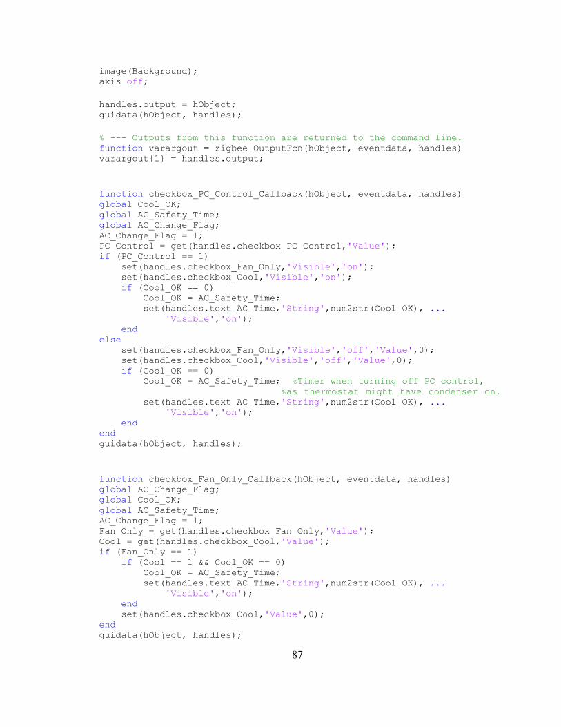
87
image(Background); axis off;
handles.output = hObject; guidata(hObject, handles);
% --- Outputs from this function are returned to the command line. function varargout = zigbee_OutputFcn(hObject, eventdata, handles) varargout1 = handles.output;
function checkbox_PC_Control_Callback(hObject, eventdata, handles) global Cool_OK; global AC_Safety_Time; global AC_Change_Flag; AC_Change_Flag = 1; PC_Control = get(handles.checkbox_PC_Control,'Value'); if (PC_Control == 1) set(handles.checkbox_Fan_Only,'Visible','on'); set(handles.checkbox_Cool,'Visible','on'); if (Cool_OK == 0) Cool_OK = AC_Safety_Time; set(handles.text_AC_Time,'String',num2str(Cool_OK), ...
'Visible','on'); end else set(handles.checkbox_Fan_Only,'Visible','off','Value',0); set(handles.checkbox_Cool,'Visible','off','Value',0); if (Cool_OK == 0) Cool_OK = AC_Safety_Time; %Timer when turning off PC control,
%as thermostat might have condenser on. set(handles.text_AC_Time,'String',num2str(Cool_OK), ...
'Visible','on'); end end guidata(hObject, handles);
function checkbox_Fan_Only_Callback(hObject, eventdata, handles) global AC_Change_Flag; global Cool_OK; global AC_Safety_Time; AC_Change_Flag = 1; Fan_Only = get(handles.checkbox_Fan_Only,'Value'); Cool = get(handles.checkbox_Cool,'Value'); if (Fan_Only == 1) if (Cool == 1 && Cool_OK == 0) Cool_OK = AC_Safety_Time; set(handles.text_AC_Time,'String',num2str(Cool_OK), ...
'Visible','on'); end set(handles.checkbox_Cool,'Value',0); end guidata(hObject, handles);
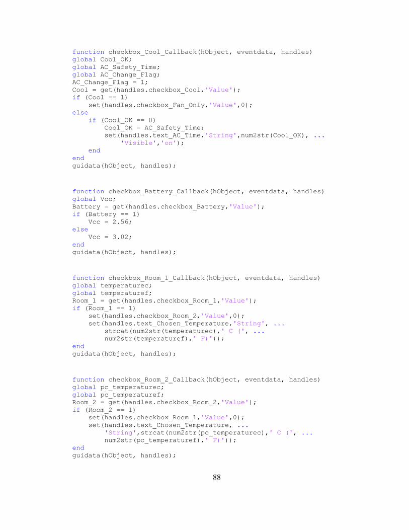
88
function checkbox_Cool_Callback(hObject, eventdata, handles) global Cool_OK; global AC_Safety_Time; global AC_Change_Flag; AC_Change_Flag = 1; Cool = get(handles.checkbox_Cool,'Value'); if (Cool == 1) set(handles.checkbox_Fan_Only,'Value',0); else if (Cool_OK == 0) Cool_OK = AC_Safety_Time; set(handles.text_AC_Time,'String',num2str(Cool_OK), ...
'Visible','on'); end end guidata(hObject, handles);
function checkbox_Battery_Callback(hObject, eventdata, handles) global Vcc; Battery = get(handles.checkbox_Battery,'Value'); if (Battery == 1) Vcc = 2.56; else Vcc = 3.02; end guidata(hObject, handles);
function checkbox_Room_1_Callback(hObject, eventdata, handles) global temperaturec; global temperaturef; Room_1 = get(handles.checkbox_Room_1,'Value'); if (Room_1 == 1) set(handles.checkbox_Room_2,'Value',0); set(handles.text_Chosen_Temperature,'String', ...
strcat(num2str(temperaturec),' C (', ...
num2str(temperaturef),' F)')); end guidata(hObject, handles);
function checkbox_Room_2_Callback(hObject, eventdata, handles) global pc_temperaturec; global pc_temperaturef; Room_2 = get(handles.checkbox_Room_2,'Value'); if (Room_2 == 1) set(handles.checkbox_Room_1,'Value',0); set(handles.text_Chosen_Temperature, ...
'String',strcat(num2str(pc_temperaturec),' C (', ...
num2str(pc_temperaturef),' F)'));
end guidata(hObject, handles);
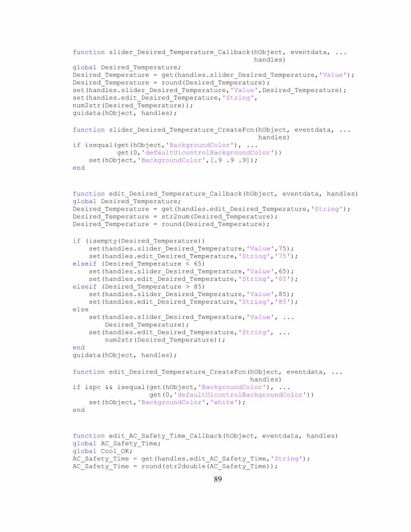
89
function slider_Desired_Temperature_Callback(hObject, eventdata, ...
handles) global Desired_Temperature; Desired_Temperature = get(handles.slider_Desired_Temperature,'Value'); Desired_Temperature = round(Desired_Temperature); set(handles.slider_Desired_Temperature,'Value',Desired_Temperature); set(handles.edit_Desired_Temperature,'String',
num2str(Desired_Temperature)); guidata(hObject, handles);
function slider_Desired_Temperature_CreateFcn(hObject, eventdata, ...
handles) if isequal(get(hObject,'BackgroundColor'), ...
get(0,'defaultUicontrolBackgroundColor')) set(hObject,'BackgroundColor',[.9 .9 .9]); end
function edit_Desired_Temperature_Callback(hObject, eventdata, handles) global Desired_Temperature; Desired_Temperature = get(handles.edit_Desired_Temperature,'String'); Desired_Temperature = str2num(Desired_Temperature); Desired_Temperature = round(Desired_Temperature);
if (isempty(Desired_Temperature)) set(handles.slider_Desired_Temperature,'Value',75); set(handles.edit_Desired_Temperature,'String','75'); elseif (Desired_Temperature < 65) set(handles.slider_Desired_Temperature,'Value',65); set(handles.edit_Desired_Temperature,'String','65'); elseif (Desired_Temperature > 85) set(handles.slider_Desired_Temperature,'Value',85); set(handles.edit_Desired_Temperature,'String','85'); else set(handles.slider_Desired_Temperature,'Value', ...
Desired_Temperature); set(handles.edit_Desired_Temperature,'String', ...
num2str(Desired_Temperature)); end guidata(hObject, handles);
function edit_Desired_Temperature_CreateFcn(hObject, eventdata, ...
handles) if ispc && isequal(get(hObject,'BackgroundColor'), ...
get(0,'defaultUicontrolBackgroundColor')) set(hObject,'BackgroundColor','white'); end
function edit_AC_Safety_Time_Callback(hObject, eventdata, handles) global AC_Safety_Time; global Cool_OK; AC_Safety_Time = get(handles.edit_AC_Safety_Time,'String'); AC_Safety_Time = round(str2double(AC_Safety_Time));
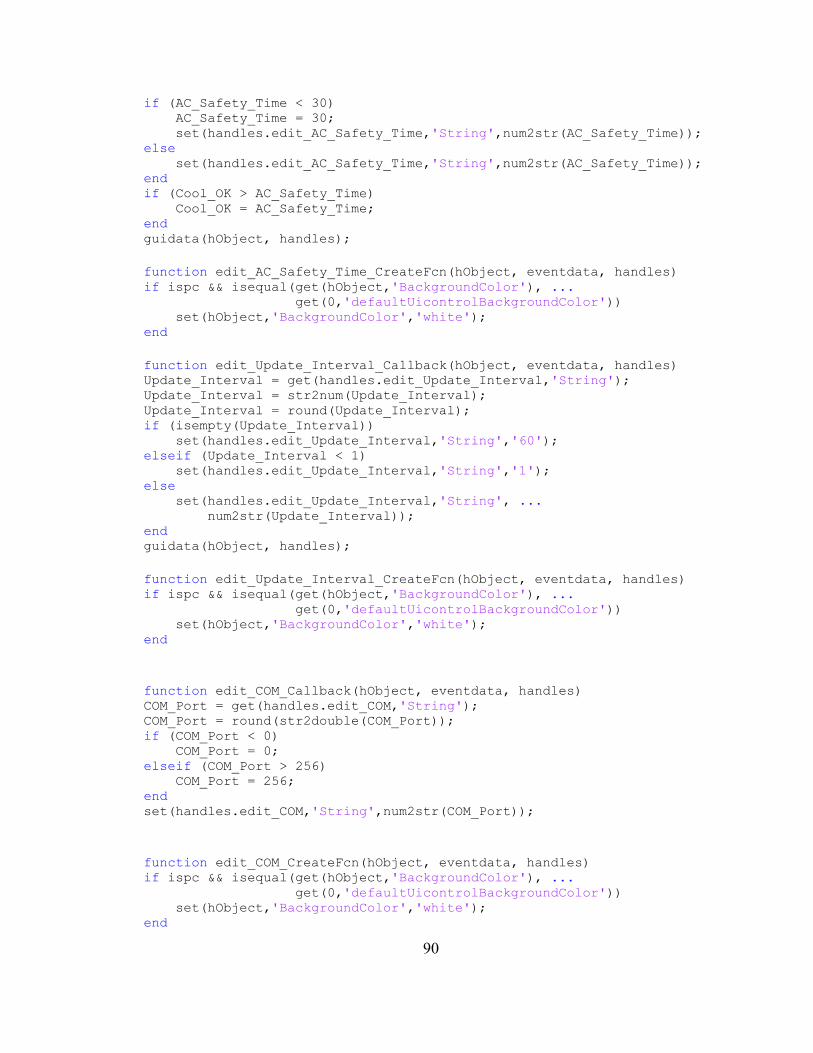
90
if (AC_Safety_Time < 30) AC_Safety_Time = 30; set(handles.edit_AC_Safety_Time,'String',num2str(AC_Safety_Time)); else set(handles.edit_AC_Safety_Time,'String',num2str(AC_Safety_Time)); end if (Cool_OK > AC_Safety_Time) Cool_OK = AC_Safety_Time; end guidata(hObject, handles);
function edit_AC_Safety_Time_CreateFcn(hObject, eventdata, handles) if ispc && isequal(get(hObject,'BackgroundColor'), ...
get(0,'defaultUicontrolBackgroundColor')) set(hObject,'BackgroundColor','white'); end
function edit_Update_Interval_Callback(hObject, eventdata, handles) Update_Interval = get(handles.edit_Update_Interval,'String'); Update_Interval = str2num(Update_Interval); Update_Interval = round(Update_Interval); if (isempty(Update_Interval)) set(handles.edit_Update_Interval,'String','60'); elseif (Update_Interval < 1) set(handles.edit_Update_Interval,'String','1'); else set(handles.edit_Update_Interval,'String', ...
num2str(Update_Interval)); end guidata(hObject, handles);
function edit_Update_Interval_CreateFcn(hObject, eventdata, handles) if ispc && isequal(get(hObject,'BackgroundColor'), ...
get(0,'defaultUicontrolBackgroundColor')) set(hObject,'BackgroundColor','white'); end
function edit_COM_Callback(hObject, eventdata, handles) COM_Port = get(handles.edit_COM,'String'); COM_Port = round(str2double(COM_Port)); if (COM_Port < 0) COM_Port = 0; elseif (COM_Port > 256) COM_Port = 256; end set(handles.edit_COM,'String',num2str(COM_Port));
function edit_COM_CreateFcn(hObject, eventdata, handles) if ispc && isequal(get(hObject,'BackgroundColor'), ...
get(0,'defaultUicontrolBackgroundColor')) set(hObject,'BackgroundColor','white'); end
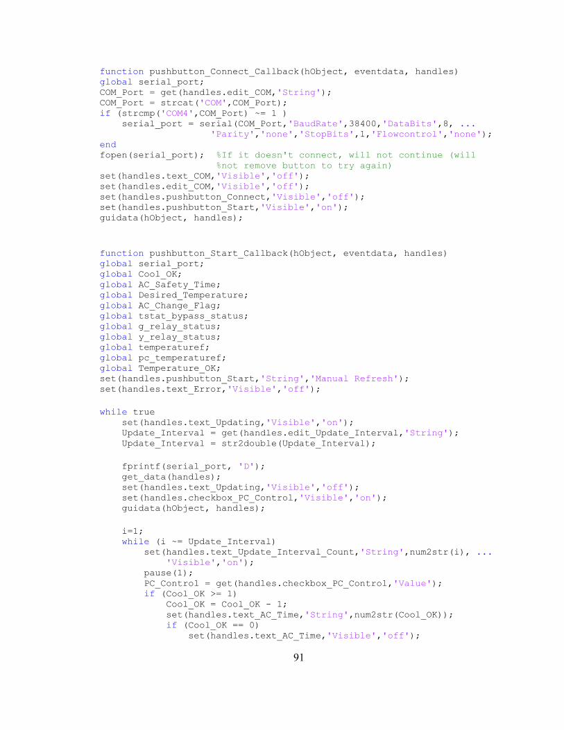
91
function pushbutton_Connect_Callback(hObject, eventdata, handles) global serial_port; COM_Port = get(handles.edit_COM,'String'); COM_Port = strcat('COM',COM_Port); if (strcmp('COM4',COM_Port) ~= 1 ) serial_port = serial(COM_Port,'BaudRate',38400,'DataBits',8, ...
'Parity','none','StopBits',1,'Flowcontrol','none');
end fopen(serial_port); %If it doesn't connect, will not continue (will
%not remove button to try again) set(handles.text_COM,'Visible','off'); set(handles.edit_COM,'Visible','off'); set(handles.pushbutton_Connect,'Visible','off'); set(handles.pushbutton_Start,'Visible','on'); guidata(hObject, handles);
function pushbutton_Start_Callback(hObject, eventdata, handles) global serial_port; global Cool_OK; global AC_Safety_Time; global Desired_Temperature; global AC_Change_Flag; global tstat_bypass_status; global g_relay_status; global y_relay_status; global temperaturef; global pc_temperaturef; global Temperature_OK; set(handles.pushbutton_Start,'String','Manual Refresh'); set(handles.text_Error,'Visible','off');
while true set(handles.text_Updating,'Visible','on'); Update_Interval = get(handles.edit_Update_Interval,'String'); Update_Interval = str2double(Update_Interval);
fprintf(serial_port, 'D'); get_data(handles); set(handles.text_Updating,'Visible','off'); set(handles.checkbox_PC_Control,'Visible','on'); guidata(hObject, handles);
i=1; while (i ~= Update_Interval) set(handles.text_Update_Interval_Count,'String',num2str(i), ...
'Visible','on'); pause(1); PC_Control = get(handles.checkbox_PC_Control,'Value'); if (Cool_OK >= 1) Cool_OK = Cool_OK - 1; set(handles.text_AC_Time,'String',num2str(Cool_OK)); if (Cool_OK == 0) set(handles.text_AC_Time,'Visible','off');
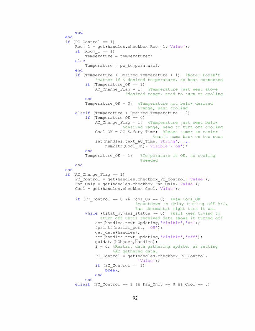
92
end end if (PC_Control == 1) Room_1 = get(handles.checkbox_Room_1,'Value'); if (Room_1 == 1) Temperature = temperaturef; else Temperature = pc_temperaturef; end if (Temperature > Desired_Temperature + 1) %Note: Doesn't
%matter if < desired temperature, no heat connected if (Temperature_OK == 1) AC_Change_Flag = 1; %Temperature just went above
%desired range, need to turn on cooling end Temperature_OK = 0; %Temperature not below desired
%range; want cooling elseif (Temperature < Desired_Temperature - 2) if (Temperature_OK == 0) AC_Change_Flag = 1; %Temperature just went below
%desired range, need to turn off cooling Cool_OK = AC_Safety_Time; %Reset timer so cooler
%can't come back on too soon set(handles.text_AC_Time,'String', ...
num2str(Cool_OK),'Visible','on'); end Temperature_OK = 1; %Temperature is OK, no cooling
%needed end end if (AC_Change_Flag == 1) PC_Control = get(handles.checkbox_PC_Control,'Value'); Fan_Only = get(handles.checkbox_Fan_Only,'Value'); Cool = get(handles.checkbox_Cool,'Value');
if (PC_Control == 0 && Cool_OK == 0) %Use Cool_OK
%countdown to delay turning off A/C,
%as thermostat might turn it on. while (tstat_bypass_status ~= 0) %Will keep trying to
%turn off until received data shows it turned off set(handles.text_Updating,'Visible','on'); fprintf(serial_port, 'OS'); get_data(handles); set(handles.text_Updating,'Visible','off'); guidata(hObject,handles); i = 0; %Restart data gathering update, as setting
%AC gathered data. PC_Control = get(handles.checkbox_PC_Control,
'Value'); if (PC_Control == 1) break; end end elseif (PC_Control == 1 && Fan_Only == 0 && Cool == 0)
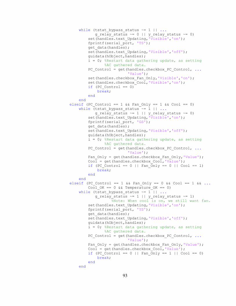
93
while (tstat_bypass_status ~= 1 || ...
g_relay_status ~= 0 || y_relay_status ~= 0) set(handles.text_Updating,'Visible','on'); fprintf(serial_port, 'TS'); get_data(handles); set(handles.text_Updating,'Visible','off'); guidata(hObject,handles); i = 0; %Restart data gathering update, as setting
%AC gathered data. PC_Control = get(handles.checkbox_PC_Control, ...
'Value'); set(handles.checkbox_Fan_Only,'Visible','on'); set(handles.checkbox_Cool,'Visible','on'); if (PC_Control == 0) break; end end elseif (PC_Control == 1 && Fan_Only == 1 && Cool == 0) while (tstat_bypass_status ~= 1 || ...
g_relay_status ~= 1 || y_relay_status ~= 0) set(handles.text_Updating,'Visible','on'); fprintf(serial_port, 'GS'); get_data(handles); set(handles.text_Updating,'Visible','off'); guidata(hObject,handles); i = 0; %Restart data gathering update, as setting
%AC gathered data. PC_Control = get(handles.checkbox_PC_Control, ...
'Value'); Fan_Only = get(handles.checkbox_Fan_Only,'Value'); Cool = get(handles.checkbox_Cool,'Value'); if (PC_Control == 0 || Fan_Only == 0 || Cool == 1) break; end end elseif (PC_Control == 1 && Fan_Only == 0 && Cool == 1 && ...
Cool_OK == 0 && Temperature_OK == 0) while (tstat_bypass_status ~= 1 || ...
g_relay_status ~= 1 || y_relay_status ~= 1)
%Note: When cool is on, we still want fan.
set(handles.text_Updating,'Visible','on'); fprintf(serial_port, 'YS'); get_data(handles); set(handles.text_Updating,'Visible','off'); guidata(hObject,handles); i = 0; %Restart data gathering update, as setting
%AC gathered data. PC_Control = get(handles.checkbox_PC_Control, ...
'Value'); Fan_Only = get(handles.checkbox_Fan_Only,'Value'); Cool = get(handles.checkbox_Cool,'Value'); if (PC_Control == 0 || Fan_Only == 1 || Cool == 0) break; end end
94
elseif (PC_Control == 1 && Fan_Only == 0 && Cool == 1 ...
&& Temperature_OK == 1) %Cool is checked,
%but not needed based on desired temp.
while (tstat_bypass_status ~= 1 || ...
g_relay_status ~= 0 || y_relay_status ~= 0) set(handles.text_Updating,'Visible','on'); fprintf(serial_port, 'TS'); get_data(handles); set(handles.text_Updating,'Visible','off'); guidata(hObject,handles); i = 0; %Restart data gathering update, as setting
%AC gathered data. PC_Control = get(handles.checkbox_PC_Control, ...
'Value'); Fan_Only = get(handles.checkbox_Fan_Only,'Value'); Cool = get(handles.checkbox_Cool,'Value'); if (PC_Control == 0 || Fan_Only == 1 || Cool == 0) break; end end end PC_Control = get(handles.checkbox_PC_Control,'Value'); Fan_Only = get(handles.checkbox_Fan_Only,'Value'); Cool = get(handles.checkbox_Cool,'Value'); if (PC_Control == tstat_bypass_status && Fan_Only == ...
g_relay_status && Cool == y_relay_status) AC_Change_Flag = 0; end end i = i + 1; end set(handles.text_Update_Interval_Count,'Visible','off'); end
function get_data(handles) global serial_port; global tstat_bypass_status; global g_relay_status; global y_relay_status; global Vcc; global temperaturec; global temperaturef; global pc_temperaturec; global pc_temperaturef; global x; global y;
pause(8); %Expected time to wait until new data comes in newdata = fscanf(serial_port);
if(isempty(newdata)) set(handles.text_Error,'Visible','on'); pause(.5); set(handles.text_Error,'Visible','off'); pause(.5); set(handles.text_Error,'Visible','on'); pause(.5);
95
set(handles.text_Error,'Visible','off'); pause(.5); set(handles.text_Error,'Visible','on'); pause(.5); set(handles.text_Error,'Visible','off'); else link_quality = sscanf(newdata(5:7),'%d'); %In dBm ambient_lighting_status = round(sscanf(newdata(27:29), ...
'%d')/2.56); %In percent from 0-100 if (Vcc == 2.56) temperaturec = sscanf(newdata(44:46),'%d')/256*Vcc*100-66.5;
else temperaturec = sscanf(newdata(44:46), ...
'%d')/256*Vcc*100-62.5; %Calibrated when
%plugged in end temperaturef = temperaturec*9/5+32; temperaturec = round(temperaturec*10)/10; %Celsius (rounded to 1
%decimal place) temperaturef = round(temperaturef*10)/10; %Fahrenheit (rounded to
%1 decimal place) ac_current = sscanf(newdata(61:63),'%d')/256*Vcc; %y = 0.3113x^3 - 0.6634x^2 + 1.2269x ac_current = 0.3113*ac_current^3 - 0.6634*ac_current^2 +
1.2269*ac_current; power = ac_current*120; %Note: Not taking into account power
%factor. (Though accurate with incand.lighting) yearly_cost = power/1000*8765.81277*0.1234; %power/1000=kW,
%8765=hours/year, 0.1234=Avg FL 2009 cost pwer kWh. ac_current = round(ac_current*100)/100; %In Amps power = round(power*100)/100; %In Watts yearly_cost = round(yearly_cost*100)/100; %In Dollars. number_of_people = sscanf(newdata(73:74),'%d'); tstat_bypass_status = sscanf(newdata(89),'%d'); g_relay_status = sscanf(newdata(99),'%d'); y_relay_status = sscanf(newdata(109),'%d'); lights_status = sscanf(newdata(118),'%d'); pc_temperaturec = sscanf(newdata(136:138),'%d')/256*300-60; %Note:
%Is never battery powered pc_temperaturef = pc_temperaturec*9/5+32; pc_temperaturec = round(pc_temperaturec*10)/10; pc_temperaturef = round(pc_temperaturef*10)/10;
set(handles.text_Number_of_People,'String', ...
num2str(number_of_people)); set(handles.text_Ambient_Lighting,'String', ...
strcat(num2str(ambient_lighting_status),'%')); set(handles.text_Temperature,'String', ...
strcat(num2str(temperaturec),' C (',num2str(temperaturef), ...
' F)')); set(handles.text_Current_Draw,'String', ...
strcat(num2str(ac_current),' A')); set(handles.text_Total_Current_Draw,'String', ...
strcat(num2str(ac_current),' A')); set(handles.text_Total_Power_Draw,'String', ...
strcat(num2str(power),' W'));
96
set(handles.text_Yearly_Cost,'String', ...
strcat('$',num2str(yearly_cost))); if (lights_status == 0) set(handles.text_Lights,'String','OFF', ...
'ForegroundColor',[0, 0, 0]); else set(handles.text_Lights,'String','ON','ForegroundColor', ...
[1, .502, 0]); end set(handles.text_Signal_Strength,'String', ...
strcat(num2str(link_quality),' dBm'));
if (tstat_bypass_status == 0) set(handles.text_PC_Control,'String','OFF', ...
'ForegroundColor',[1, 0, 0]); set(handles.text_Fan_Label,'Visible','off'); set(handles.text_Fan,'Visible','off'); set(handles.text_Cool_Label,'Visible','off'); set(handles.text_Cool,'Visible','off'); else set(handles.text_PC_Control,'String','ON', ...
'ForegroundColor',[0, .757, 0]); set(handles.text_Fan_Label,'Visible','on'); set(handles.text_Fan,'Visible','on'); set(handles.text_Cool_Label,'Visible','on'); set(handles.text_Cool,'Visible','on'); end if (g_relay_status == 0) set(handles.text_Fan,'String','OFF','ForegroundColor', ...
[1, 0, 0]); else set(handles.text_Fan,'String','ON','ForegroundColor', ...
[0, .757, 0]); end if (y_relay_status == 0) set(handles.text_Cool,'String','OFF','ForegroundColor', ...
[1, 0, 0]); else set(handles.text_Cool,'String','ON','ForegroundColor', ...
[0, .757, 0]); end set(handles.text_PC_Temperature,'String',
strcat(num2str(pc_temperaturec),' C (', ...
num2str(pc_temperaturef),' F)')); Room_1 = get(handles.checkbox_Room_1,'Value'); if (Room_1 == 1) set(handles.text_Chosen_Temperature,'String', ...
strcat(num2str(temperaturec),' C (', ...
num2str(temperaturef),' F)')); else set(handles.text_Chosen_Temperature,'String', ...
strcat(num2str(pc_temperaturec),' C (', ...
num2str(pc_temperaturef),' F)')); end
97
for i=1:20 y(i)=y(i+1); end y(21) = power; set(handles.text_Recent_Power_Use,'Visible','on'); axes(handles.axes_Power); stem(x,y,'Color',[.263, .294, .482],'MarkerSize',2); if (max(y) ~= 0) set(handles.axes_Power,'YLim',[0 max(y)]); else set(handles.axes_Power,'YLim',[0 240]); end set(handles.axes_Power,'XTickLabel','','YGrid','on'); ylabel('Watts');
end
function figure1_CloseRequestFcn(hObject, eventdata, handles) global serial_port; global tstat_bypass_status; set(handles.text_Closing,'Visible','on'); if (tstat_bypass_status == 1) i = 1; while (tstat_bypass_status ~= 0 && i <= 3) %When closing program,
%let uC know to go back to thermostat
%(stop trying after a few tries though) fprintf(serial_port, 'OS'); get_data(handles); guidata(hObject, handles); i = i + 1; end end if (strcmp(serial_port.status,'open') == 1) fclose(serial_port); end delete(hObject);
98
REFERENCES
1E & Alliance to Save Energy. (2009, March 25). PC Energy Report 2009. Retrieved
March 26, 2009, from http://www.1e.com/EnergyCampaign/downloads/
PC_EnergyReport2009-US.zip
Adams, J., & Heile, B. (2006, October). Busy as a ZigBee. Retrieved March 16, 2009,
from http://www.spectrum.ieee.org/oct06/4666
Air802 LLC. (2005). FCC Rules and Regulations. Retrieved March 14, 2009, from
http://www.air802.com/fcc-rules-and-regulations.html
Atmel Corporation. (2009). ZigBee FAQ. Retrieved February 21, 2009, from
http://www.meshnetics.com/zigbee-faq/
Bluetooth. (2009, March 15). Wikipedia, The Free Encyclopedia. Retrieved March 16,
2009, from http://en.wikipedia.org/wiki/Bluetooth
Digi International Inc. (2009). Digi Wireless Products. Retrieved March 16, 2009, from
http://www.digi.com/products/wireless/
Digi-Key Corporation. (2007). ZigBee Technology Product Training Module (PTM).
Retrieved February 21, 2009, from http://dkc1.digikey.com/us/en/tod/Freescale/
ZigBee/ZigBee.html
Energy conservation. (2009, February 16). Wikipedia, The Free Encyclopedia. Retrieved
February 16, 2009, from http://en.wikipedia.org/wiki/Power_conservation
99
Freescale Semiconductor, Inc. (2009). BeeKit Wireless Connectivity Toolkit. Retrieved
March 16, 2009, from http://www.freescale.com/webapp/sps/site/
prod_summary.jsp?code=BEEKIT_WIRELESS_CONNECTIVITY_TOOLKIT
Freescale Semiconductor, Inc. (2008). Freescale IEEE 802.15.4 Development Kits.
Retrieved March 16, 2009, from http://www.freescale.com/files/wireless_comm/
doc/brochure/BRIEEE802154DKIT.pdf
Google Inc. (2009). Energy Information. Retrieved February 11, 2009, from
http://www.google.org/powermeter/
Home automation. (2009, February 7). Wikipedia, The Free Encyclopedia. Retrieved
February 16, 2009, from http://en.wikipedia.org/wiki/Home_automation
IEEE Computer Society. (2007, August 31). 802.15.4a. Retrieved March 14, 2009, from
http://standards.ieee.org/getieee802/download/802.15.4a-2007.pdf
Jamieson, P. (2008, February 28). ZigBee Application Profiles. Retrieved March 16, 2009,
from www.zigbee.org/imwp/idms/popups/pop_download.asp?ContentID=12618
Jennic Ltd. (2007). Jennic's ZigBee e-learning Course. Retrieved February 21, 2009,
from http://www.jennic.com/elearning/zigbee/files/content_frame.htm
P3 International Corporation. (2008). P3 - Kill A Watt. Retrieved March 19, 2009, from
http://www.p3international.com/products/special/P4400/P4400-CE.html
Phase-shift keying. (2009, March 6). Wikipedia, The Free Encyclopedia. Retrieved
March 14, 2009, from http://en.wikipedia.org/wiki/BPSK
Standby power. (2009, March 26). Wikipedia, the Free Encyclopedia. Retrieved March
26, 2009, from http://en.wikipedia.org/wiki/Standby_power
100
Tendril Networks, Inc. (2008). Smart Energy Made Easy. Retrieved March 18, 2009,
from http://www.tendrilinc.com/wp-content/uploads/smart-energy-guide.pdf
Tendril Networks, Inc. (2008). Tendril Products. Retrieved March 18, 2009, from
http://www.tendrilinc.com/consumers/products/
U.S. Department of Energy. (2008, September). 2008 Buildings Energy Data Book.
Retrieved March 22, 2009, from http://buildingsdatabook.eren.doe.gov/docs/
DataBooks/2008_BEDB.pdf
U.S. Department of Energy. (2008, October). EERE: Energy Savers Tips. Retrieved
March 26, 2009, from http://www1.eere.energy.gov/consumer/tips/pdfs/
energy_savers.pdf
Vision for the Home - ZigBee Wireless Home Automation. (2006, November). Retrieved
March 19, 2009, from http://www.zigbee.org/imwp/idms/popups/
pop_download.asp?contentID=10254
ZigBee Alliance. (2009). ZigBee Alliance. Retrieved March 11, 2009, from ZigBee
Alliance: http://www.zigbee.org
ZigBee Alliance. (2009). ZigBee Smart Energy. Retrieved March 18, 2009, from
http://www.zigbee.org/Markets/ZigBeeSmartEnergy/tabid/224/Default.aspx
ZigBee Alliance. (2009, March). ZigBee Wireless Sensor Applications for Health,
Wellness and Fitness. Retrieved March 18, 2009, from http://www.zigbee.org/
imwp/download.asp?ContentID=15585
ZigBee and RF4CE Set New Course For Consumer Electronic Remote Controls. (2009,
March 3). Retrieved March 16, 2009, from http://www.zigbee.org/imwp/
download.asp?ContentID=15438
101
ZigBee. (2009, February 16). Wikipedia, The Free Encyclopedia. Retrieved February 16,
2009, from http://en.wikipedia.org/wiki/ZigBee