hmi - epshl.de · nachdem wir das programm nun fertig gestellt haben, muss es ebenfalls in die sps...
TRANSCRIPT

HMI‐Visualisierung

‐Inhalt‐
Teaminformationen………………. 3 Zeitlicher Rahmen…………………. 4 Aufgabenstellung………………….. 5 STEP 7……………………………………. 6 ‐ 9 Win CC Flexible……………………… 10 ‐ 13 Anwendung in der Industrie…. 14 Schluss………………………………….. 15
‐Content‐
Team information….………………. 18 Time‐frame…………..………………. 19 The Task…………….……………..….. 20 STEP 7………………………………..…. 21 ‐ 24 Win CC Flexible……………………… 25 – 28 The use in the industry………….. 29 The End..……………………………….. 30

‐Teaminformationen‐
Kristof Herr
Da ich noch sehr unentschlossen bin, welchen Beruf ich später praktizieren will, entschied ich mich für Maschinenbautechnik, da dieser Berufszweig eine gesicherte Zukunft bietet. Außerdem kann man mit einem „Ing.“ in Maschinenbau viel erreichen und von der Welt sehen.
Aleksandar Vulinovic
Technik hat mich schon immer sehr interessiert. Die Vielfalt dieser Richtung gibt mir viele Möglichkeiten für meine spätere Berufswahl. Zuerst möchte jedoch Maschinenbautechnik studieren.
Tilo Hoppenrath
Ich habe schon früher immer gerne an meinem Moped „gebastelt“. Nun dachte ich mir, warum nicht Hobby zum Beruf machen? Da viel meine Wahl auf Maschinenbautechnik, weil sie dem ja schon ziemlich nah kommt, sowie auch anderen Themen aus dem Kurs.

‐Zeitlicher Rahmen‐
Unser Lehrer Herr Oelke hat uns zwei Möglichkeiten für unsere Bewertung gegeben. Zum einen schlug er uns vor eine ganz „normale“ (quasi unmögliche) Klausur zu schreiben. Zum anderen konnten wir uns für eine selbständige Projektarbeit entscheiden. Da wir Schüler dumm und naiv waren, haben wir uns für die zweite Möglichkeit entschieden. Vom xx.xx.2007 bis zum 24.01.2008 hatten wir Zeit, unsere von Herrn Oelke aufgetragenen Projekte, in epischer Breite und teils englischer Sprache, in Form einer Mappe abzugeben.

‐Aufgabenstellung‐
Ziel unseres Projektes bestand darin, eine Bohrvorschubmaschine mittels eines Touchpanels zu visualisieren.
Erster Schritt in Richtung Lösung war die Programmierung der Bohrvorschubmaschine via STEP 7. STEP 7 ist die aktuelle Programmiersoftware der Firma Siemens und ist der Nachfolger von STEP 5.
Dies ist die Bohrvorschubmaschine. Sie ist mit vier Pneumatischen Zylindern, welche jeweils Endlagenschalter besitzen ausgestattet. Zu bedienen ist diese Maschine mittels einer Schaltkonsole, welche wir in unserer Aufgabe durch ein Touchpanel der Firma Siemens ersetzen sollten.
Dieses ist das Touchpanel TP 170C der Firma Siemens. Die Schaltkonsole der Bohrvorschubmaschine haben wir auf diesem Gerät visualisiert, wodurch die Maschine auch nichtstationär bedient werden kann.

‐STEP 7‐
‐Die Programmierung der Bohrvorschubmaschine‐
Erster Schritt war die Programmierung der Bohrvorschubmaschine. Als uns klar war, dass es sich um eine Ablaufsteuerrung handelt, da sich Signale überschneiden, wussten wir auch welche Planungswerkzeuge von Nöten waren. Wir begannen mit einem Funktionsdiagramm, nachdem wir uns über die Ablaufreihenfolge der verschiedenen Zylinder im klaren wurden.
Dies ist eine stark vereinfachte Variante eines Funktionsdiagramms.
Als nächstes haben wir alle Zylinder usw. in die Symboltabelle eingetragen und adressiert.

Dies ist unser Hauptbaustein, der OB1‐ Objektbaustein. In ihm sind alle anderen Bausteine wie zum Beispiel der Funktionsbaustein untergebracht.
Um die bestimmten Funktionen später in der Ablaufkette auszuwählen, mussten wir hier die entsprechenden Symbole zuweisen.

Nach dem Eintragen aller Symbole und dem Deklarieren aller Variablen im OB1 haben wir eine Ablaufkette im Funktionsbaustein 1 (FB1) erstellt. Hierzu fügten wir die Variablen aus der Symboltabelle in der richtigen Reihenfolge in die Ablaufkette ein. Die einzelnen Schritte (Steps) werden durch Transitionsbedingungen getrennt. Der erste Schritt ist der Initialisierungsschritt, bei dem alles „rückgesetzt“ wird.
R = rücksetzte S = setzte
Nach dem letzten Schritt wird die Ablaufkette wieder mit der Position nach dem Initialisierungsschritt verknüpft.

Damit wäre der Programmierteil der Bohrvorschubmaschine beendet. Als nächstes stand der erste Test an. Zum Testen mussten wir jedoch erst einmal das fertige Programm in die SPS laden. Hierzu markierten wir alle Bausteine und klickten auf laden.
Sobald das Programm in die SPS (speicherprogrammierte Steuerrung) geladen wurde, konnten wir mit dem Test beginnen. Nun mussten wir noch die Kabel (Eingang/Ausgang) von der SPS mit der Schaltkonsole verbinden. Die Bohrvorschubmaschine wurde mit Strom und Druckluft versorgt und konnte so in Betrieb genommen werden.
Nach einigen erfolgreichen Tests, widmeten wir uns nun der Programmierung des Programms für das Touchpanel via Win CC Flexible.

‐Win CC Flexible‐
‐Die Programmierung des Touchpanels‐
Da wir absolut kein Wissen über diese Programmierung verfügten, mussten wir uns dieses erst einmal aneignen. Informationen fanden wir reichlich auf der DVD von Herrn Oelke. Das Meiste jedoch fanden wir nur durch probieren und testen heraus. Das Erste, was wir machen mussten, war die beiden Programme („STEP 7“ und „Win CC Flexible“) miteinander zu verbinden. Hierzu wählten wir bei STEP 7 die Option HMI‐Station einfügen. Von nun an ist Win CC Flexible in STEP 7 integriert.
Nun begannen wir mit der Programmierung des Touchpanels. Wir starteten mit der Überlegung, was überhaupt an dem ganzen Prozess visualisiert werden sollte. Entschieden haben wir uns für die Zylinderstände und die Schaltkonsole samt Menüführung und anderen Informationen. Unser erstes „Bild“ war das Hauptmenü, von dem aus man Unterpunkte wie Prozessvisualisierung, Informationen zum Panel und dem Team erreichen kann. Eine Oberfläche herzustellen, war nicht sehr schwer, da das Programm sehr benutzerfreundlich und intuitiv ist. Auf der nachfolgenden Seite ist unser Hauptmenü in Win CC Flexible zu sehen. Auf der rechten Seite sind die Werkzeuge, mit denen man jegliche Objekte erstellen kann. Sie sind einfach per „Drag and Drop“ auf dem „Touchpanel“ in der Mitte zu platzieren. Markiert man eines der Objekte, kann man es in der unteren Bildhälfte mit diversen

Optionen verändern. Links unter Projekt, findet man alle Informationen über das Projekt und auch die Verbindung zu STEP 7.

Unter Kommunikation muss man die Variablen aus STEP 7 integrieren. Es ist darauf zu achten, dass alles was bei STEP 7 ein Eingang ist, bei Win CC Flexible ein Ausgang werden muss und umgekehrt!
Dies ist unsere Variablentabelle Als wir alle Variablen eingetragen hatten, begannen wir sie mit unseren Objekten zu verknüpfen, damit das Objekt „weiß“, wann es sich bewegen soll oder welche Aktion es beim Auslösen ausführen soll.
Wir haben den Objekten bestimmte Ereignisse zugewiesen, wie zum Beispiel „setze Bit“, und dann die dementsprechende Variable ausgewählt. Dies haben wir mit allen Objekten gemacht, die wir auf dem „Touchpanel“ platziert haben.

Als nächstes haben wir uns an die „Bildnavigation“ gemacht. Sie „sagt“ dem Programm, welches Bild das Startbild ist und welches Bild nach dem aktivieren kommt.
Hierzu haben wir einfach die Bilder rechts aus der Liste per „Drag and Drop“ auf die Fläche in die Mitte gezogen. Mit einem Rechtsklick konnten wir nun noch den Startbildschirm festlegen. Nachdem wir das Programm nun fertig gestellt haben, muss es ebenfalls in die SPS geladen werden. Dies haben wir unter dem Menüpunkt „Projekt – Transfer“ erledigt. Da nun beide Elemente „versorgt“ waren (Die Bohrvorschubmaschine mit dem STEP 7 Programm und das Touchpanel mit dem Win CC Flexible Programm), konnten wir nun beides miteinander verbinden. Nun haben wir nur noch die Bohrvorschubmaschine mit Strom und Druckluft, und das Touchpanel nur mit Strom versorgt. Beides eingeschaltet und schon hatten wir unsere Aufgabe gelöst!

‐Anwendung in der Industrie‐
Die einfache Bedienung und die vielseitige Einsetzbarkeit machen die Visualisierung per Win CC Flexible zu einem unerlässlichen Teil in der Industrie. Es können kleinere Prozesse (wie z.B. unser Projekt) damit Visualisiert werden. Der hauptsächliche Anwendungsbereich findet sich jedoch in größeren Maschinen und Anlagen (z.B. Bierbrauerei, Fertigungsfabriken etc.). Komplexe Vorgänge können mit Win CC vereinfacht dargestellt und bedient werden. Ein Netzwerk zwischen mehreren Stationen erleichtert die Kommunikation zwischen den Mitarbeitern. Ebenfalls ist es kein Problem neue Variablen wie (z.B. einen Sensor) einzufügen und diese graphisch auf einem Display darzustellen. Eine kurze Bedienungsanleitung genügt schon, um eine größere Maschine bedienen zu können. Genau diese Vorteile machen Win CC Flexible so unersetzlich im Bereich der Industrie. Ich konnte mir sogar persönlich, über die praktische Anwendung von Win CC in einem Praktikum, in einer Bierbrauerei, einen Eindruck verschaffen. Alle Stationen (Sudhaus, Gär,‐ und Lagerkeller und die Abfüllanlage) waren mit Win CC ausgerüstet. Auf Computerbildschirmen konnte man mit nur wenigen Klicks verschiedene Funktionen wie z.B. das Befüllen eines Tanks durchführen. Der Verlauf von Bier, Wasser oder Reinigungsmittel konnte genau verfolgt werden. Flüssigkeiten konnten bis auf den Liter genau in einen der vielen Tanks geleitet werden. Auch waren die Füllstände der verschiedenen Tanks oder Temperaturen gut dargestellt. Fast jeder Mitarbeiter der Bierbrauerei konnte das Programm bedienen. Die verschiedenen Sensoren in den Tanks zeigten auch den CO² Wert und den Druck an. Ein Warnungssystem informierte den jeweiligen Mitarbeiter, ob Überdruck herrscht. Dies konnte mit wenigen „Klicks“ korrigiert werden. Zusammenfassend kann man sagen, dass Win CC die Bedienung komplizierter Anlagen vereinfacht.

‐Schluss‐
Das war die Dokumentation zu dem HMI‐Visualisierung Projekt von Kristof Herr, Alexander Vulinovic und Tilo Hoppenrath. Wir hatten sehr viel Spaß und Erfolgserlebnisse. Jedoch auch Frust und suizidale Momente ;‐) . Es hat uns Freude gemacht, neue Wege und Lösungen für das Projekt zu finden und wir waren besonders glücklich, wenn alles lief, wie geplant. Frustriert waren wir, als wieder einmal 15 Fehler auftauchten und nix klappte, die Lizenzen abgelaufen waren und der Lehrer nur grinsend Sprüche klopfte.
Nichts desto trotz war es ein tolles Erlebnis, welches wir nicht mehr missen wollen!
Unser Quellenverzeichnis fällt recht kurz aus, da wir sehr gute Unterlagen auf einer von Herrn Oelke bereitgestellten DVD hatten.
Eigenständigkeitserklärung
Hiermit bestätigen wir (Kristof Herr, Alexander Vulinovic und Tilo Hoppenrath), dass die vorgelegte Dokumentation unseres Projektes in eigenständiger und alleiniger Arbeit angefertigt wurde. Die verwendeten Materialien wurden unsererseits erstellt oder von Herrn Oelke bereit gestellt.
________________________ ________________________ ________________________
Kristof Herr Aleksandar Vulinovic Tilo Hoppenrath
________________________
Ort , Datum
VIELEN DANK

English

HMI‐Visualisation

‐Team information‐
Kristof Herr
Because of my undecidedness about choosing a profession, I decided to choose engineering, because this profession has got a safe future. In addition you can see a lot of the world as a graduate engineer.
Aleksandar Vulinovic
I was interested in engineering all my life. The variety of this course gives me a lot of possibilities for my profession choice. I would like to become an engineer, but at first I have to study engineering.
Tilo Hoppenrath
I used to tinker at my moped when I was young. And now I thought:”Why don’t make my hobby to my profession?” So I choose engineering, because it is that kind of work I like. And I like all the other topics of the course, too.

‐Time‐frame‐
Our teacher Mr. Oelke gave us two possibilities for our evaluation. On the one hand he proposed us to write a completely normal (quasi impossible) class exercise. Because of our naivety and stupidity we decided for the second possibility. We had time from xx.xx.2007 to 24.1.2008 to submit the projects in the form of a folder, written in English and including epical width.

‐The Task‐
The aim of our project was to visualize a drill feed machine, by dint of a Touchpanel.
First step to the solution was the programming of the drilling feed machine via STEP 7. STEP 7 is the current programming software of Siemens. It is the replacement of STEP 5.
This is the drilling feed machine. It is equipped with four pneumatic cylinders. All pneumatic cylinders have got limit switches. To operate the machine there is a switch bar, which we had to exchange with a touchpanel from Siemens.
This is the touchpanel TP 170C from Siemens. We have visualized the switch bar on this touchpanel, to give the ability to use the machine non‐ stationary.

‐STEP 7‐
‐The programming of the drill feed machine ‐
First step was the programming of the drilling feed machine. As we realized, that this was a sequence control system, we knew which planning tools we had to use. Having figured out the functional order of the cylinders, we started to develop a functional diagram.
This is a simplified version of a functional diagram.
For the next step, we entered and addressed all cylinders etc. in the symbol chart.

This is our main programme module, the OB1‐ Object module. This module contains all the other ones e.g. the function module.
To use the features in the feed sequence, we had to assign them with our symbols from the symbol chart.

Having entered all the symbols and declared all the variables in the OB1, we have compiled a feed sequence in the function module 1 (FB1). For this we inserted the variables of the symbol chart with the right order into the module. The single steps are separated by transition conditions. The first step is the initialization step in which everything is "reset“.
R = reset S = set
After the last step the feed sequence is linked with the position after the initialization step.

With this the programming part of the drilling feed machine is finished. The next step was the first test. For testing we had to load the completed program into the SPS first. For this we marked all modules and activated the load button.
As soon as the program was loaded into the SPS we could start the test. Now we still had to link the cables (input/output) of the SPS with the switch bar. The drilling feed machine was supplied with electricity and compressed air and finally we could start the machine operation.
After a couple of successful tests, we were addressed ourselves to the programming of the program for the touchpanel via Win CC Flexible.

‐Win CC Flexible‐
‐The Programming of the touchpanel‐
Since we did not know much about this programming, we had to acquire the necessary knowledge. We received lots of information from the DVD of Mr. Oelke. But most of information we figured out by experiments and tests. First of all we had to link both programs („STEP 7“and "Win CC Flexible“). For this we chose the option HMI‐Station at STEP 7 and inserted it. Now the Win CC Flexible is integrated in Step 7.
Now we began with the programming of the touchpanel. We started to consider which things we should visualize at the process. Finally we decided to focus on the cylinder position, the switch bar, the menu navigation and other information. Our first “picture“was the main menu, from which you can reach sub‐categories like process visualizing, information about the panel and the team. Producing a surface was quite easy, because the program was very user‐friendly and intuitive. On the following page you can see our main menu in Win CC Flexible. On the right hand side you can see the tools, with which you can create any kind of objects. They are simply placeable via “Drag and Drop” in the middle of the "touchpanel“. If you mark one of the objects, you can change it with lots of options in the lower part of the surface. On the left hand side beneath the project you can find all the

information about the project, even the connection to Step 7. Under "communication” you have to integrate the variables from Step 7.

It is important to care about the fact, that everything which is an input in Step 7 becomes an output in Win CC Flexible and the other way around.
This is our chart of variables. As we entered all the variables, we started linking them with our objects so that the object "knows“ at what time it has to move or to act after releasing.
We assigned the objects to certain events, e.g. "set bit“, and after that we chose and selected the variable. We applied this procedure to all the objects, which we have placed on the touchpanel.
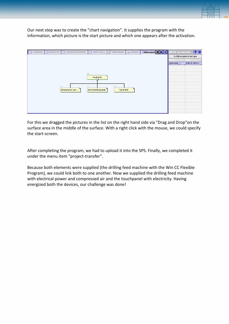
Our next step was to create the “chart navigation”. It supplies the program with the information, which picture is the start picture and which one appears after the activation.
For this we dragged the pictures in the list on the right hand side via "Drag and Drop“on the surface area in the middle of the surface. With a right click with the mouse, we could specify the start‐screen. After completing the program, we had to upload it into the SPS. Finally, we completed it under the menu item "project‐transfer“. Because both elements were supplied (the drilling feed machine with the Win CC Flexible Program), we could link both to one another. Now we supplied the drilling feed machine with electrical power and compressed air and the touchpanel with electricity. Having energized both the devices, our challenge was done!

‐The use in the industry‐
The simple operation and it’s universalism makes the visualisation via Win CC Flexible to an irreplaceable part of the industry. You can visualize little projects like ours, but the main application range is in larger machines e.g. in a brewery or in factories. Win CC Flexible simplifies complicated procedures. A network with some stations makes the communication much easier. It is also no problem to enter new variables like a sensor and visualise them on a display. A short entering guide is enough to operate a machine. And this is exactly the point that makes Win CC Flexible so important for the modern industry. One of our team‐mates got a field‐tested impression in a brewery. All parts of the brewery were equipped with a panel programmed with Win CC Flexible. On the screens you could do a lot of options with some simple “clicks” e.g. the filling of a tank. The course of fluids like beer, water and cleaning supplies could be viewed on the screens, too. Almost all the workers were enabled to use the systems in the brewery. Sensors in the tanks were controlling the pressure in the tanks. If the pressure was too high, each worker were enabled to correct it with some “clicks”. To sum up the text, you can say, that Win CC Flexible simplifies complicated machines.

‐The End‐
This is the documentation of the HMI – Visualisation project of Kristof Herr, Aleksandar Vulinovic and Tilo Hoppenrath. We had a lot of fun and many successful moments, but also frustration and suicidal moments. It was a pleasure to find new solutions for the project and we were very happy, when the things ran like intended. The most frustrating moments were, when we suddenly got 15 mistakes, the licenses ran out of date and the teacher was joking around and grinning.
Nevertheless, this was a fantastic experience, which we don’t want to miss!
Our source chart is really short, because we found plenty of information on Mr. Oelke’s DVD.
Declaration
Herewith, we Kristof Herr, Aleksandar Vulinovic and Tilo Hoppenrath confirm, that this documentation of our project is a product of our own work. The materials and the information which we used are self‐made or provided by Mr. Oelke.
________________________ ________________________ ________________________
Kristof Herr Aleksandar Vulinovic Tilo Hoppenrath
________________________
Place, Date
Thank you