hmald 6. g~lpgew and parrii craf* - fs.fed.us · pdf filein our research has a capacity of...
TRANSCRIPT

hmald 6. G~lpgeW and E, Parrii Craf*
USDA FOREST SERViGE RESEARCH PAPER NE-328 1975
FOREST SERVICE, U. S. DEPARTMENT Of AGRICULTURE NORTHEASTERN FOREST EXPERIMENT STATION 6816 MARKET STREET, UPPER DARBV, PA. 19082
F, BRYAN CLARK, STATION DIRETOR

DONALD G, C&TPETT received his bachelor sf science degree in forestry from West Virginia University in 1950, In 1950-52 he served as a farm forester for the West Virginia State Forestry Department, and in 1953-54 as assistant state forester, In 1955 he joined the 'Union Carbide Corporation as a forester, becoming department head in 1958, a position he held until 11962, when he joined the staff of the Northeastern Forest Experiment Station, Forest Products Mar- keting Laboratory, at Princeton, W. Va,, as research forester and project leader,
E, PAUL GRAFT recehed his bachelor of science degree in forestry from %Vest Virginia University in 1951, From 1951 through 1961 he served private industry as a bourbon-stave inspector, sta've-mill man- ager, and f ieid representative for heavy construction and industrial equipment, In 1962 he joined the staff sf the Northeastern Porest Experiment Station, Forest Products Narketing Laboratpry, at Princeton, "tW, Va-, where he has served as head of engineerxng ser- vices, equipment specialist* and associate market analyst,
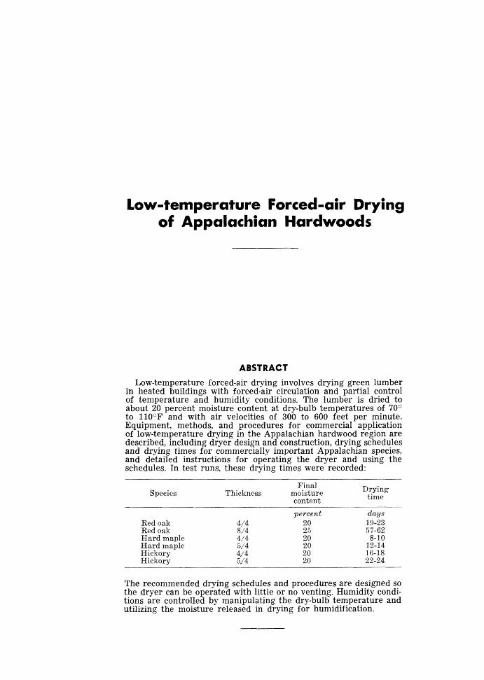
Low-temperature Forced-air Drying of Appalachian Hardwoods
ABSTRACT
Low-temperature forced-air drying involves drying green lumber in heated buildings with forced-air circulation and partial control of temperature and humidity conditions. The lumber is dried to about 20 percent moisture content at dry-bulb temperatures of 70° to 11O0F and with air velocities of 300 to 600 feet per minute. Equipment, methods, and procedures for commercial application of low-temperature drying in the Appalachian hardwood region are described, including dryer design and construction, drying schedules and drying times for commercially important Appalachian species, and detailed instructions for operating the dryer and using the schedules. In test runs, these drying times were recorded:
Species Final
Thickness moisture content
Drying time
percent da?4s Red oak 414 2 0 19-23 Red oak 81'4 25 57-62 Hard maple 414 2 0 8-10 Hard maple 514 2 0 12-14 Hickory 4i4 2 0 16-18 Hickory 5/4 20 22-24
The recommended drying schedules and procedures are designed so the dryer can be operated with little or no venting. Humidity condi- tions are controlled by manipulating the dry-bulb temperature and utilizing the moisture released in drying for humidification.

IN 1967 WE BEGAN RESEARCH to eval- ua te low-temperature forced-air drying of
Appalachian hardwoods. In our initial study, we compared drying times, costs, and de- grade losses for low-temperature drying vs. a i r drying of 4i.3, Appalachian red oak ( 2 ) . We have now developed low-temperature dry- ing schedules and procedures for other thick- nesses of oak, and for several thicknesses of other impodant Appalachian woods. This re- port includes a discussion of dryer design, drying schedules, and dryer operating pro- cedures for commercial use in the Appal- achian region.
Low-temperature drying was developed to alleviate some of the problems involved in air-drying lumber in open yards. The low- temperature method involves drying the lum- ber in totally enclosed heated buildings hav- ing internal forced-air circulation systems. Green lumber is dried to about 20 percent moisture content a t temperatures of 70' to l l O O E " and with a i r velocities of 300 to 600 feet per minute.
Low-temperature drying is much faster than air-drying. For most species and thick- nesses of Appalachian hardwoods, low-temp- erature drying times are about onethird of the average air-dl-y.ing times, Therefore low- temperature drying requires only one-third of the lumber inventory necessary for air- drying an equivalent volume of lumber.
The low-temperature method also permits better control of drying degrade than air- drying does. In the Appalachian region,
degrade losses in commercial air-drying op- erations average about 5 percent of lumber value. In commercial low-temperature dry- ing, degrade losses can be limited to 1 or 2 percent of lumber value.
LOW-TEMPERATURE DRYER DESIGN
Two general types of low-temperature drying facilities a re in commercial use : low-temperature kilns and low-temperature dryers. Low-temperature kilns are equipped with automatic controls for the heating, humidification, and vent systems ( I ). Low- temperature dryers have thermostats for temperature control and either manual con- trols or humidistats for the humidification and vent systems. Similar building construc- tion, fan systems, and other design features are used for both types of drying csquipment. However, the drying schedules, procedures, and related information in this report apply only to low-temperature dryer operation.
Dryer Size and Gapaci+y The capacity of commercial units varies
from 12 to more than 100 thousand board feet. But most of the dryers used for oak and similar hardwoods are in the 25-40 50- thousand board-foot range. The dryer used in our research has a capacity of about 25 thousand board feet of 4J4 lumber, or about 28 thousand board feet of W4 lumber. The building is 28 feet wide by 36 feet long and holds four kiln-car loads of box-piled lumber

Figure I .---The csmmercial-scale experiments! low-temperafure dryer used in developing dsying schedules for Appalashian hardwoods, and a partial kiln-truck load of 8/4 red oat lumber. The dryer: is of pole-Sypo frame csnstruc+ion, sided with ex- Perior plywood.
on two tracks. Each load is 8 feet wide, 16 feet long, and about I f feet high (fig. 1).
F o r dryers having larger capacities, a four-track dryer is preferable to a longer two-track dryer. The former provides greater capacity per square foot of building size, and greater capacity per number of fans and per horsepower required to operate the fan systelx.
Building Cons+ruc+ion
The drying building must house the Itam- ber, fans, and heating system; and it must have adequate ~~llentlm-space to facilitate a i r flow. Aside from these general requirements, availability and cost of local building mater- ials are the most important considerations in selecting type of building,
A variety of building types can be used, The most eomnlorl are pole-type buildings clad with plywood, lumber, metal, or con~posi- tion-board siding, and with metal or aspl~alt roll roofing (figs. 2, 3, and 4). Buildings hav- ing masonry-block or studded-wall construe- tion can also be used. In some ir?stanees,
existing buildings such as drying sheds have been converted successfully for use a s low- temperature dryers.
For track-loaded dryers, floors can be earthen, crushed stone, asphalt, or concrete. Earthen and crushed stone floors should be underlain wit11 a polyethylene vapor barrier (fig. 2 ) . Dryers designed for forklift loading should have paved Aoors o r runways. The pavement and base should be adequate for supporting the forklift during loading and unloading operations. See local state highway codes for pavement and base requirements,
The walls of dryers having lumber, ply- wood, o r metal siding fastened to purlins or studs should h a ~ e an inner wall of jh-inch asphalt-impregnated insulation board to pro- vide an insulating air space. The inner wall should be underlain with a 6-mil pol>-ethylene vapor barrier (fig. 2 ) - The interior surfaces of masonry block walls should be coated with a commercial kiln coating.
Roofing can be insulated by fastening in- sulation board or 10-mil polyethylene film underneath the rafters o r roof purlins to

Figure 2.-Front elevation of typical dryer with fans located overhead.
Figure 37Fronf elevafion of Vpical dryer designed wifi dans locafsd on floor bafle,
3

Figure 4.-Side view of a commercial low-temperature dryer. The building is of pole-type frame construction, sided and roofed with corrugated metal. The south slope of roof contains clear panels to absorb solar energy.
provide an air space. The polyetl~ylene film should be stretched tight, stapled to the raft- ers, and secured by narrow wood strips.
Because of current high fuel costs and the need for fuel conservation, further insula- tion of dryer buildings is probably war- ranted. A recent analysis of our experimental dryer by a local heating engineer showed that the addition of I$$ inches of fiberglass or equivalent insulation to the walls, doors, and roof would result in sufficient fuel sav- ings to repay the cost of insulation in about 2 years,
Doors can be constructed of 2-inch wood f r a ~ ~ ~ i n g , sheathed on the outside with metal or exterior plywood and co-i~ered on the in- side with 1h-inch asphalt-inipregnated insula- tion board. The i~?sulation board should be underlain with a 6-mil polyethylelle vapor barrier, and tlie air space in the door sl~ould be filled with fiberglass insulation. Doors can
be either hinged or bung on a track system. The latter is preferable for dryers eon- structed for forklift loading, because of the large doors required. One advantage of the track-loaded dryer design is that fewer and smaller doors can be used; this results in fewer cracks a t door joints and consequently less heat loss.
Hea+inq S ysferns
Low-temperature dryers can be heated by steam, hot water, or direct forced-air sys- tems. In some instances, dryers a re heated entirely by surplus or exhaust steam. About I boiler-horsepower or equivalent per thou- sand board feet of dryer capacity is required to achietTe the desired dry-bulb temperatures,
In addition, dryers can be designed to utilize solar heat for supplementing conven- tional heating systems. To aid in the absorp- tion of solar energy-, dryer roofs, exterior

door surfaces, and exterior wall surftaees (except for masonry block walls) should be painted black. Dryers having metal roofs can b e modified to absorb additional solar e n e r m by alternating the metal roofing panels with translucent fiberglass panels on the southernmost side of the dryer (figs. 2 and 4). Energly transmitted through the fiberglass is collected on the black-painted a ~ u m i n u m panels locat4 underneath and parallel to the fiberglass roof panels; a i r from the fans passes over both sides of the aluminum panels and distributes the heat throughout the dryer. If the dryer roof is ceiled to provide an insulating air spaee, the roof sections beneath the fiberglass panels should be ceiled with clear polyethylene film.
The dryer heating system must be ar- ranged so that heat is distributed evenly along a line perpendicular to the direction sf a i r Aow, for the entire length of the build- ing. 41n addition, the system should be de- signed so that the a i r will not pass through more than 16 feet of lumber without being r e h e a t d .
Fan System
Dryer fan systems should produce a i r velocities of 500 to 6600 feet per minute through the lumber (4, 6). Such a i r velocities are attained most economically by large- diameter multiblade fans run a t low speeds. For example, to provide .a given volume of a i r p e r minute, a 6-foot fan turning a t 2'70 rpm will require only about 10 percent of the power needed for a %foot fan turning a t 1,100 rpm ( 3 ) .
Loads should be baHed at Aoor, ceiling, and ends to force a i r through the lumber and prevent it bppassing around the load (figs. 2 and 3). Also, where 4 x 4s are used as package separators, the openings should be covered with narrow boards. To further facilitate a i r Aow, the dryer should be de- signed to provide a. minimum of 4 feet of clear spaee f plenun~) between the outside walls and the adjacent loads and between the roof and ceiling bafies (fig, 2 ) .
A typical overhead fan system for a 2- track dryer is shown in fig. 5 , The four 6-foot fans, dritren by two 7'y2 horsepower motors,
provide a mean a i r velocity of about 500 feet per minute through a load containing 25 thousand board feet of 414 lumber. The load consists of 63 layers of box-piled lumber (random widths and lengths), with ad total load len@b of 32 feet. For a 4-track dryer of 50 thousand board-foot capacityy, the same number and size of fans, powered by two 10- horsepower motors, would produce similar a i r velocities ( 1 ) .
The fan system can also be located on a floor bame about 1 foot above ground level (fig. 3 ) . Where this arrangement is used, the building has to be about 6 feet wider than is needed for dryers with overhead fan sys- tems. However, the roof trusses for dryers with overhead fan systems are heavier and more expensive than those used in dryers with floor-level fan systems. Thus, overall costs of dryers with the two types of fan systems are about equal.
For dryers having total load widths ex- ceeding 8 feet, fan motors should be pro- vided with switch gear and time clocks to permit automatic reversal of air flow a t intervals of 3 to 6 hours. Separate controls should be provided for each motor in the fan system; this will permit operation of only two fans when lower a i r velocities are de- sired for dry-ing 614 and 814 oak, beech, and hickory (see schedule 4) .
Low-temperature dryers can be provided with humidification systems and vents. But in most eases, neither is required for the dry- ing schedules and procedures given in this report. Humidity conditions can be controlled adequately by manipulating the dry-bulb temperature and utilizing the moisture re- Ieased in drying for humidification.
For most species and thicknesses of Ap- palachian hardwoods, cracks around the doors provide sufieient venting for efficient dryer operation. But in some locations, addi- tional venting may be needed in the early stages of drying yejflo-iv-poplar, basswood, butternut, and buckeye. The additional vent- ing can be obtained from a 12-incli-diameter louvered fan located in the gable a t one end of the dryer (fig. I ) . The fan can be con- trolled either manually or by a humidistat set to turn on the fan the wet-bulb

FORCED-AIR DRYER
FAN SYSTEM
W END VIEW
W
7 112 HP MOTORS
PP
PLAN VIEW
Figure 5.-Overhead fan system used in .).he dryers illustrated in figures 2 and 4. The fan system can also be located on a floor baffle abou+ I foot above ground level (fig. 3).

Table I ,--Low-temperature drying schedules for Appalachian hardwoods
Dry-bulb Webbub Step No. Moisture content temperature depressions
SCHEDULE 1 1 Green to 40% 75" to 85°F 4" F 2 40 t o 20% 95°F No control Air velocity 450-600 feet per minute ; vents closed.
SCHEDULE 2 1 Green to 40% 70" to 80°F 3" F 2 40 to 25% 90°F No control
Air velocity 500 to 600 feet per minute; vents closed.
SCHEDULE 3 1 Green to 45% 80" to 90" 7°F 2 45 to 20% 100" F No control Air velocity 450-600 feet per minute; vents closed.
SCHEDULE 4 1 Green t o 40% 70" to 80°F 3°F 2 40 to 25% 90°F No control Air velocity 250-350 feet per minute; vents closed.
a Step-2 wet-bulb deprwsions can normally be maintained only for the first day or two of drying.
depression is less than that listed in step 1 of t h e appropriate drying schedule (table 1).
Loading Method
Dryers can be designed for loading and unloading with either track or forklift. Choice of loading method depends mainly on the lumber-handling facilities and methods used by- the firm. Total space required for the dryer and loading area is about the same for both loading methods. Forklift loading
requires a level space about 30 feet wide in front of each entry; track loading requires a simiIar Ievel area on each side of the tracks.
LOW-TEMPERATURE SCHEDULES
Schedules for drying rough-sawn Appa- lachian hardwoods are shown in table 1. Species and thicknesses that can be dried on each schedule are as follows:
Species Schedule I Schedule 2 Schedule 3 Schedule 4
Red oak White oak Beech Hickory Hard maple Soft maple Cherry Bireh Yellow-poplar Basswood Butternut Buckeye Ash Black walnut

OPERATING PROCEDURES The sample board (kiln-sample) system
should be used for monitoring drying pro- gress ( 5 , chapter V I ) . An equal number of samples should be selected from the slower drying stock (wide, thick, quarter-sawn boards) and the faster drying stock (nar- row, thin, plain-sawn boards.) Use one sample per kiln-truckload or per 5,000 board feet of lumber.
Establishing the step 1 wet-bulb depres- sion is the most important procedure in using the drying schedules. As the dryer warms up, the wet-bulb temperature rises with the dry-bulb temperature for a while, then be- gins to lag behind. This lag (wet-bulb depression) increases as the dry-bulb temp- erature increases. Using larger step-1 wet- bulb depressions then specified in the schedules can result in objectionable check- ing, particularly when drying oak, beech, and hickory.
During the warm-up phase of drying, dry- bulb and wet-bulb temperatures should be determined with a psychrometer (fig. 6) . Temperature readings should be made a t the air-inlet side of the load. After step-t dlrying conditions are established, dry-bulb temp- eratures can be monitored with the thermo- meter attached to the dryer thermostat.
The following procedures should be fol- lowed for drying a charge of lumber (sehed- ule 1 is used as an example) :
1. After the dryer is loaded and bames are i n place, turn on the heat and fans, and set the dryer thermostat a t 85OF (maxi- mum step-1 dry-bulb temperature for schedule 1 ) .
2. Determine the wet-bulb depression about once an hour, beginning when the dry- bulb temperature reaches 75OF (mini- mum step-1 dry-bulb temperature for schedule 1 ) .
3. When a 4OF wet-bulb depression is ob- tained, reset the thermostat a t the pre- vailing dry-bulb temperature ; however, do not use a thermostat setting higher than 85" or lower than 75OF. Note: It is not necessaw to maintain the initial wet-bulb depression throughout
Figure 6,WSling- and fan-type psychrometers. Either type can be used for determining wet-bulb depres- sion during early stages o f drying.
step 1. After a day or two of drying, the wet-bulb temperature will decrease slowly; but the change will not b e fast enough to eause objectionable drying degrade.
4. During warm, sunny weather, solar heat will eause daytime dry-bulb temperatures to exceed thermostat settings by vaulyjing anaounts (fig. 7) . If during step 1 t h e d w - bulb temperature exceeds the thermostat setting by more than S0F, lovcrer the thermostat setting by- 5OF and maintain the lower setting throughout step 1.
5. When the samples have dried to am av- erage moisture content of 40 percent (step 2 beginnix~g moisture content), re- set the dryer thermostat a t 95OF (s tep 2 dry-bulb temperature for schedule 1 ) . Maintain this setting until the samples reach the desired final moisture corntent.
The amount of time required to dry green lumber to step 2 beginning moisture contrtnt

Figure 7.-Temperature chart made while drying a charge of lumber on schedule I. Solar he&+ caused +he dry-bulb temp- erature +o exceed fhe 80°F thermosfair sefiring about two-thirds of each 24-hour period.
varies considerably, even for a given species and thickness, The following a re examples for several charges we have dried on the different schedules :
Drying Lime, green to
Thkhess Schedule step2 a d spedes No. beginning
moisture conbnd
514 beech 4/4 red oak 41'4 hiekory 514 hickory 514 red oak 814 red oak 614 soft rnapIe 4f 4 yeflow-poplar 614 yellow-poplar
Special care should be taken when drying 6/4 oak and 814 oak, beech, and hiekory. The green lumber should be end-coated, stickered, and placed in the dryer as soon as possible after sawing. Lise only enough fans to pro- vide 250 to 350 feet per minute a i r velocity through the lumber (see scliedule 4) . Even with these precautions, objectionable check- ing may take place in some charges of ltrm- ber. i5'11en this occurs, the fans should he operated only at night until the lumber dries to 40 percent average moisture content.
Table 2 shows tlie range of time required for drying several species and thicknesses of rough green lumber on schedules 1 through 4. Five-quarter and thicker red and white oaks should be dried to about 25 percent

Table 2.-Low-temperature drying times for green lumber
[Appalachian hardwoods]
Species Final average Thickness moisture content Drying time
Inch quarters
Red oak ........................ 4/4 51 4 8/ 4
White oak .................... 4/4 5/4 8/ 4
............................ Beech 4/4 5/ 4
.................. Soft maple 4/4 5/4 51 4
Hard maple ................ 4/4 5/4
Hickory ........................ 4/4 5/4
Percent
2 0 25 2 5 2 0 2 5 2 6 2 0 2 0 2 0 2 0 12 2 0 20 2 0 2 0
average moisture content. At lower moisture contents, the drying rates a re too slow to justify the cost of dryer operation. The 4/4 red and white oaks, and 4 / 4 through 8/4 thicknesses of other Appalachian species, should normally be dried to 20 percent av- erage moisture content. But for 4 / 4 and 514 soft maple, beech, yellow-poplar, basswood, buckeye, and butternut, satisfactory drying ra tes can be maintained to about 15 percent average moisture content,
LITERATURE CITED (1) Catterick, J .
1970. COSTS OF tow TEMPERATURE DRYING. North Logger 18 (9) : 18, 50, 60.
(2) Cuppett, Donald G., and E. Paul Craft. 1971. b~-TENIPER~~TURE DRYING OF 414 APPA- LACHIAN RED OAK. Fo r Prod. J. 21(1) :34-39, illus.
(3) Devine, John. [n.d.] PRODUCTION KILN-DRYING. 154 p., illus. [Publisher unknown.]
(4) Gaby, L. I. 1961. FORCED-AIR DRYING OF SOUTHE;RN PINE. USDA For. S e n . Res. Pap. SE-121, 20 p., illus. Southeast. For. Exp. Stn., Asheville, N. @.
(5) Rasmussen, E. F. 1961. DRY K I L N OPERATOR'S MANUAL. U. S. Df3~. Agric., Agric. Handb. 188. 197 p., illus.
(6) Rucker, Tinsley VCT., and Walton R. Smith. 1961. FORCED-AIR DRYING O F LUMBER-RESEARCH AND EXPERIMENTAL. For. Prod. J. 11 (9) :390-394, illus,