high-temperature low-cycle fatigue behavior of … · it has become apparent that the fatigue life...
TRANSCRIPT

HIGH-TEMPERATURE LOW-CYCLE FATIGUE BEHAVIOR OF HAYNESe 230@ SUPERALLOY
L. J. Chen, Y. H. He, and P. K. Liaw
Department of Materials Science and Engineering The University of Tennessee Knoxville
Knoxville, TN 37996-2200
J. W. Blust and P. F. Browning
Solar Turbines Inc. 2200 Pacific Highway, P. 0. Box 85376, MZ R-l
San Diego, CA 92186-5376
and
R. R. Seeley and D. L. Klarstrom
Haynes International, Inc. 1020 West Park Avenue, P. 0. Box 9013
Kokomo, IN 46904-9013
Abstract hold time.
Total strain-controlled low-cycle fatigue tests and stress intensity factor range (AK)-controlled crack growth tests without and with hold times, as well as stress relaxation tests were conducted at high temperatures for a nickel-chromium-tungsten- molybdenum HAYNES 230 superalloy sheet material. The influences of test temperature and hold time on low-cycle fatigue and crack growth behavior were determined. The low- cycle fatigue life shows a strong dependence on test temperature and hold time. At all test conditions used in this investigation, the alloy exhibits strain hardening followed by softening. The crack growth rate per cycle was found to increase with longer hold time. Scanning electron microscope (SEM) observations show that crack initiation occurred in either transgranular or intergranular mode, while the crack propagated in either transgranular or mixed transgranular and intergranular mode. These cracking modes were dependent on test temperature and
Introduction
HAYNES 230 alloy is a solid-solution strengthened nickel- chromium-tungsten-molybdenum superalloy that possesses excellent high temperature strength, outstanding resistance to oxidizing and nitriding environments, very good long-term thermal stability, and excellent forming and welding characteristics. The primary solid solution strengthening element is tungsten. The alloy is used for making high-temperature components in the aerospace, power, chemical process, and industrial heating industries. These high-temperature components generally operate under very severe conditions. Frequently, they are subjected to cyclic loading at elevated temperatures, which can lead to high-temperature, low-cycle fatigue failure. Therefore, the problem of high-temperature, low- cycle fatigue is of great importance to the design of these high-
Superalloys 2000 Edited byT.M. Pollock, R.D. Kissinger, R.R. Bowman,
K.A. Green, M. McLean, S. Olson, aad J.J. Schima TM.7 (The Minerals, Metals &Materials Society), 2000
573

temperature components.
It has become apparent that the fatigue life under high- temperature, low-cycle fatigue conditions depends not only on testing temperature but also on waveform. Generally, in studies concerning the total strain-controlled high-temperature, low- cycle fatigue, the fatigue life was observed to decrease with increasing test temperature”-3’. A great amount of studies indicated that the incorporation of hold time may have a pronounced effect on the cyclic life of nickel base superalloys14- ‘I. Moreover, many investigations concerning the fatigue crack initiation and propagation modes have shown that at elevated temperatures, damage was usually caused by fatigue and creep mechanisms, depending on the number of cycles and duration of hold time’y-‘3’. Both transgranular and intergranular cracking have been observed in nickel-based superalloys after testing.
Extensive research studies show that crack growth in various materials at high temperatures can be cycle-dependent, time- dependent, or a combination of both, depending on the type of the alloy and the test conditions. Such factors as test temperature, test frequency, hold time, loading ratio, initial microstructure, and environment can significantly affect crack growth. In the studies on wrought nickel-based WASPALOY superalloy”4’, it was found that the general effect of increase in temperature was to give faster fatigue crack growth rates by a factor of about three from 550 to 700°C. Moreover, for 300 seconds hold cycling, the effects of temperature on the fatigue crack growth rate were very dramatic. With increasing temperature from 550 to 650°C. there was a severe increase in crack growth rates by up to a factor of 13. However, a reduction in da/dN values was observed with increase in test temperature from 650 to 700°C. Fatigue crack growth rates have also been found to increase generally with the decrease in test frequency or the addition of hold time “‘-“]. In the tests on INCONEL’“’ alloy 718, Diboine and Pineau ““’ found that the introduction of a one minute hold time resulted in an increase in fatigue crack growth rates which were twice the growth rates measured under continuous cycling. Gayda, Gabb, and Miner “‘I showed a systematic increase in da/dN with the test frequency ranging
from 0.02 to 5 Hz in Rem? 95 fatigue tested in air at 650°C.
Inc. and received in the solid-solution annealed condition. The final annealing temperature was 1,232”C. The nominal chemical composition of the alloy is given in Table I’*“‘. The examination of the microstructure was carried out using optical microscopy. The micrographs of metallographic sections of the alloy are shown in Figure I. It can be noted that the alloy is essentially composed of austenitic grains with some annealing twins. In addition, a small amount of white second phase particles can be also observed, as indicated by arrows in Figure l(b). It has been
In this investigation, high-temperature, low-cycle fatigue and crack growth tests using a range of cyclic periods ranging from one second to five hours, as well as stress relaxation experiments were conducted to determine the influence of testing temperature and hold time on the low-cycle fatigue behavior of HAYNES 230 alloy. Another goal of this research was to develop improved life prediction methods and data for the design of combustor liners manufactured from sheet metal products.
Test Material and Procedures
The HAYNES 230 alloy was supplied by Haynes International,
Figure I : The initial Microstructure of HAYNES 230 alloy (as-received)
determined that these second phase particles are M& carbides in which M is primarily tungsten’*“.
The low-cycle fatigue specimens used in this investigation were rectangular, with a thickness of 3.2 mm. The geometry of specimens is shown in Figure 2. All fully reversed pull-push low-cycle fatigue tests with and without hold times were performed in laboratory air employing a computer-controlled Material Test System (MTS) servohydraulic testing machine. A
Element
Content
(a) As balance
Table I Nominal Chemical Composition of HAYNES 230 alloy (Weight Percent)
Ni Cr W MO co Fe B
57Q’ 22 14 2 5’ 3% 0.015’
*Maximum 574

continuously monitor the physical crack length on the specimens. Electric potential probes were attached to the front face of the specimen on either side of the specimen notch. Current leads were attached to the top and bottom of the specimen in order to provide a uniform current flux in the specimen gage section. The crack length was obtained by passing a constant current through the specimen, and measuring the potential drop between the two potential probes. The crack length is related to the change in the otential drop by a relationship known as Johnson’s P equationt23 :
Figure 2: Geometry of low-cycle fatigue specimen (mm)
a +
$a 9.6
Figure 3: Geometry of compact tension specimen (mm)
high frequency induction generator was used to heat the specimen. The fluctuation of test temperature was maintained within a range of &2?C. An axial total strain-range control mode was applied. A high-temperature extensometer was used to measure the axial strain. The extensometer was spring-loaded, and has two ceramic legs which were in direct contact with the gage-length area of the specimen. The extensometer was cooled by the forced air during high-temperature, low-cycle fatigue testing. The cyclic frequency of 1 Hz was used. For the high- temperature, low-cycle fatigue tests without hold time, the test temperatures of 760°C to 982°C were used, and the imposed axial total strain range was varied in the range of 0.25 to 1.0%. In the case of hold-time tests, the chosen test temperatures were 816’C and 927°C respectively. In addition, a 120 seconds, 600 seconds, or infinite tensile hold time were introduced at the maximum tensile strain of each cycle. The imposed total strain range was 1.0%. All tests were run to failure.
All crack growth data were generated using the compact-tension specimen shown in Figure 3. The specimens have a thickness of 3.2 mm. Creep-fatigue crack growth specimens were prepared from the sheet materials in accordance with American Society for Testing and Materials (ASTM) standards E647-86t221. Creep- fatigue crack propagation tests were conducted on an Instron servo-controlled, hydraulically actuated, and closed-loop test machine. An electric potential system, consisting of a constant current supply and a multiple gain amplifier, was used to
575
Where U, and a0 are the initial values of the potential and crack length, U and a the instantaneous values of the potential and crack length, y one half the probe gage length, and W the specimen width. In addition, a high-temperature clip gage was placed across the crack mouth opening to measure the crack opening displacement. The specimens were precracked to approximately 1.27 mm. The final AK used during precracking was 20 MPa& . The precracking was performed at a R-ratio of 0.1, using a triangular waveform at a frequency of 10 Hz. All crack growth tests were conducted in laboratory air at a temperature of 816°C under the constant AK control mode. A AK level of 27.5 MPa & and a R-ratio of 0.05 were employed. A triangular waveform and a frequency of 0.333 Hz were used in the crack growth test without hold time. Crack growth experiments with various hold times ranging from 3 to 18,000 seconds were conducted using a baseline frequency of 0.333 Hz with superimposed hold times at maximum load. Crack growth rates at different test conditions were determined through computer analyses of the crack length versus either number of cycles or time data using an apparent linear fitting program.
The fracture surface of some specimens subjected to low-cycle fatigue and creep-fatigue crack growth tests were examined using a Cambridge S-320 scanning electron microscope (SEM) in order to determine the crack initiation and propagation mode.
Test Results and Analvsis
Strain Fatigue Life Behavior
The Effect of Temuerature For high-temperature, low-cycle fatigue without hold time, the curves of the fatigue life versus total strain range at different test temperatures are shown in Figure 4 t241 It can be seen that the low-cycle fatigue properties . of HAYNES 230 alloy exhibit some dependence on the test temperature and imposed total strain range. At total strain ranges less than 0.7%, the low-cycle fatigue life of the alloy decreased significantly with increasing test temperature in the range of 760°C to 982°C. At a total strain range of l.O%, it was found that the fatigue life of the alloy did not decrease with increasing test temperature, as observed in other superalloy systems. In the

temperature range of 760°C to 871°C, increasing the test temperature led to a significant reduction in the fatigue life of the alloy, while the fatigue life of the alloy appeared to increase with test temperature in the 871°C to 927°C range.
:::
E3 . 0.8
&J 5 ; 0.6
.I
g 2 0.4 3 0
b 0.2
0 871oC
v X 927°C
o A v 982oC
V
vo3A w 0
?A :: 0
v
oat * 102 103 104 105 106
Number of cycles to failure
Figure 4: Fatigue life as a function of total strain range at different temperatures
“YY
t
AE~ = 1.0%
700 Tensile hold time
A- 816OC
4- 927oC
0 5 10 15 zu
Hold time, min
Figure 5: Fatigue life as a function of strain hold time
The Effect of Hold Time The low-cycle fatigue life of the alloy as a function of hold time is illustrated in Figure 5. It can be noted that the introduction of the tensile strain hold time resulted in a reduction of the fatigue life of the alloy. The amplitude of reduction in fatigue life appeared to be related to the test temperature and duration of tensile strain hold. Although the alloy showed a longer fatigue life at 927°C than at 816°C under the continuous cycling conditions, all low-cycle fatigue tests with hold times gave the shorter fatigue lives at 927°C than at 816°C.
576
Cyclic Stress Resnonse Behavior
The cyclic stress response behavior of nickel-based superalloys under continuous cycling has been reported extensively in the literature. It has been demonstrated that their cyclic stress response is closely related to factors like the type and initial microstructure of alloy, test temperature, and strain rate. Some micromechanisms have been suggested to explain the cyclic hardening and softening phenomena occurring during cyclic deformationr25-271.
Vecchio, Fitzpatrick, and Klarstromt211 found in their study on low-cycle fatigue properties of HAYNES 230” alloy at three different temperatures of 760, 871, and 982°C that the alloy usually exhibited cyclic hardening. It appears that the degree of cyclic hardening, which was defined as the midlife stress amplitude divided by the first-cycle stress amplitude, would decrease with increasing test temperature from 760 to 982°C.
6 3s” I &>;.Y.”
a,? 300 \ \
3 \
.Z ‘-0 ‘;: f 250
t
816OC
m -O-with no hold z I --o--with2minhold ; 200
t ---A--- with 10 min hold
1501 100 101 102
Number of cycles
400 (b)
3.50 - cd
Es? $300 - - 9-d
3
&5- J c-
---t -- El * E 250 - 927oC \
i
c- A---*
:H.Y.,- _
16 F2
t
-m-with no hold ‘i
iz --•--with2minhold ;j 200 --A--- with 10 min hold
1501 B **1*111’ ’ ’ *lS1ll’ ’ ““u 100 101 102
Number of cycles
L
103
Figure 6: Cyclic stress response curves of HAYNES 230 alloy during low-cycle fatigue with and without hold time at (a) 816°C and (b) 927°C

Figures 6(a) and (b) illustrate the cyclic stress response curves for the strain hold times at 816°C and 927°C respectively. It can be noted from the figures that the alloy showed an initial strain hardening to a peak stress followed by a period of softening. It is apparent that the number of cycles to reach the peak stress decreased due to the addition of a hold time. At 816”C, the cyclic stress response behavior of the alloy was similar in the early stage of cyclic deformation for low-cycle fatigue tests without and with hold time. However, it is notable that at 927”C, both tests with the tensile hold time showed a higher level of cyclic stress amplitude than continuous cycling in the initial stage of cyclic deformation. For the low-cycle fatigue test with a hold time of 2 minutes, the cyclic stress amplitude remained at a higher level throughout the test as compared to continuous cycling and the test with a 10 minute hold time.
350
Infiite hold time 300
t c a
3 2.50 - n
G 200 - z
2 ‘E 150 -
3 m - 3
loo
b m so-
t + 816oC
--o- 927W
lo-5 lo-4 10-s 104 1w loo 101 102 103
Time, hr
Figure 7: Stress relaxation curves of HAYNES 230@ alloy
Infinite hold time
-.--816oC 0.8
+927W
0.6
0 50 100 150 200
Time, set
Figure 8: The amount of stress relaxation relative to time in the early stage of hold
577
Stress Relaxation Behavior
The stress relaxation curves of HAYNES 230 alloy at both temperatures of 816°C and 927°C during low-cycle fatigue with infinite hold time are shown in Figure 7. It can be observed that HAYNES 230 alloy showed similar stress relaxation behavior at both test temperatures used in this investigation. At the beginning of an infinite hold, a very rapid drop of the tensile stress occurred, while during the remaining period, comparatively less additional stress relaxation took place. The kinetics of stress relaxation during infinite hold was also similar at temperatures of 8 16°C and 927’C, with the majority of stress relaxation occurring within the initial 50 seconds.
In order to clearly show the dependence of the stress relaxation behavior on test temperature, the amount of stress relaxation
104
lo-7 lo-2 10-I 100 10’ 102
Cycle time, min
lo-4
lo-7 * lo-2
L
lo-1 loo 101 102 103
Cycle time, min
Figure 9: Crack growth rates in HAYNES 230 at 816°C. Solid symbol refers to cycling with no hold time.
t i (b) 816oC
AK = 27.5 MPam*‘z
0 0
0
0
0
0 0 0

occurring in the early stage of infinite hold tests relative to time is depicted in Figure 8. In the figure, or represents the initial maximum tensile stress, and ~ra is the relaxed stress at different times. It is obvious that increasing test temperature resulted in greater amounts of stress relaxation.
Influence of Hold Time on fatigue Crack Growth Rate
The crack growth rate data obtained from tests conducted at 816°C and different cycle times are presented in Figure 9. As seen in Figure 9(a), the introduction of a hold time at maximum loading led to a significant increase in the crack growth rate per cycle compared with that under continuous cycling. As expected, the crack growth rate per cycle increased with increasing hold time. It was also noted that at hold times less than 2 minutes, the increase in da/dN with hold time was lower. However, at the hold times above 10 minutes, da/dN showed a rapid and nearly linear increase.
When the crack growth per unit time (da/dt) is plotted versus cycle time, the crack growth rate is found to decrease with
increasing hold time, as shown in Figure 9(b). The crack growth rate per unit time decreases rapidly at the shorter hold times and begins to reach a stable value at the longer hold times, indicating that time-dependent effects are beginning to dominate the rate of crack propagation at the longer hold time.
There existed an immediate relationship between da/dN and da/dt, which could be expressed as follows:
daldt)
where da/dN is measured in m/cycle, da/dt in m/min, f is the test frequency for continuous cycling and measured in Hz, and th is the hold time per cycle and measured in minutes. Using equation (2), the conversion between da/dN and da/dt can be easily done. Dash line in Figure 9(a) represents the corresponding da/dN values at different hold times calculated from equation (2) using actually obtained da/dt data given in Figure 9(b). It is obvious that the measured value of da/dN is considerably consistent with the calculated value.
Figure IO The typical SEM photographs of fracture +ml~c\ 101 low-cycle iat~guc tc\t\ (a) 816°C IO minute hold time; (b) 927°C wrthout hold time (c) 927”C, IO minute hold time; (d) 8 16°C 2 minute hold time
578
SEM Analvsis of Fracture Surface
Examination of the fracture surfaces of the low-cycle fatigue and creep-fatigue crack growth tested specimens was performed in a scanning electron microscope. Figure 10 shows the typical SEM photographs of fracture surfaces obtained under different test conditions. There existed multiple crack initiation sites on all fracture surfaces, which originated entirely from the surface of specimens. For all of low-cycle fatigue tests with and without hold times performed at 816°C it was observed that crack initiated in a transgranular mode, as exemplified in Figure IO(a) for the test with a IO minute hold time. At 927”C, the crack initiation mode was also found to be transgranular in low-cycle fatigue tests without hold time and with a 2 minute hold time, as exemplified in Figure IO(b). However, for the test with a IO minute hold time, it can be seen that crack initiated intergranularly, as shown in Figure 10 (c).
For all low-cycle fatigue tests carried out in this investigation at both temperatures of 816 and 927”C, crack propagation occurred
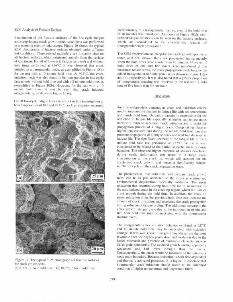
Figure I I The typical SEM photographs of fracture surfaces for crack growth tests (a) 816”C, I hour hold time; (b) 816°C 5 hour hold time
predominately in a transgranular manner, even if the hold time of IO minutes was introduced. As shown in Figure IO(d), well- defined fatigue striations can be seen on the fracture surfaces, which are considered to be characteristic features of transgranular crack propagation.
The SEM observations on creep-fatigue crack growth specimens tested at 816°C showed the crack propagated transgranularly when the hold times were shorter than IO minutes. However, if hold times of one and five hours were introduced at the maximum tensile stress, the crack propagation mode became the mixed transgranular and intergranular, as shown in Figure I l(a) and (b), respectively. It was also noted that a greater proportion of intergranular cracking was observed in the test with a hold time of five hours than for one hour.
Discussion
Such time-dependent damages as creep and oxidation can be used to interpret the changes in fatigue life with test temperature and tensile hold time. Oxidation damage is responsible for the reduction in fatigue life especially at higher test temperatures because it tends to accelerate crack initiation and to assist the propagation process of a fatigue crack. Creep taking place at higher temperatures and during the tensile hold time can also promote propagation of a fatigue crack and lead to a decrease in fatigue life. The significant decrease of the fatigue life in the 2 minute hold time test performed at 927°C can be at least considered to be related to the particular cyclic stress response behavior. The observed higher response of stresses developed during cyclic deformation can result in a large stress concentration at the crack tip, which will account for the accelerated crack growth, and hence, a significantly reduced number of cycles in the crack propagation stage.
The phenomenon, that hold time will increase crack growth rates, can be in part attributed to the stress relaxation and environmental degradation, especially oxidation. The stress relaxation that occurred during hold time led to an increase of the accumulated strain in the crack tip region, which will induce crack growth during the hold time. In addition, the crack tip stress relaxation from the previous hold time can increase the amount of crack tip sliding and accelerate the crack propagation during subsequent fatigue cycling. The additional increase in the crack growth rate per cycle due to the introduction of one and five hour hold time may be associated with the intergranular fracture mode.
The intergranular crack initiation behavior exhibited at 927°C and IO minute hold time may be associated with oxidation damage. It was well known that grain boundaries are the most favorable sites for oxygen penetration and oxidation due to the lattice mismatch and presence of oxidizable elements, such as Cr, at grain boundaries. The oxidized grain boundary apparently weakened, and had lower strength than the matrix. Consequentially, the crack would be localized on the inherently weak grain boundary. Because oxidation is both time-dependent and thermally-activated processes, it is logical to conclude that intergranular crack initiation should occur at the combined condition of higher temperatures and longer hold times.
579

Conclusions
Based above analysis and discussion, the following conclusions can be made: 1. During low-cycle fatigue with tensile hold times, HAYNES 230 alloy usually exhibited cyclic hardening followed by softening. 2. The fatigue life of HAYNES 230 alloy generally decreased due to the introduction of the tensile hold time. 3. The stress relaxation behavior showed that at the beginning of strain hold, the stress dropped very quickly and then decreased very slowly with increasing time. 4. The creep-fatigue crack growth rates of HAYNES 230 alloy exhibited a strong dependence on the tensile hold time. With increasing tensile hold time, da/dN increased, while da/dt decreased. 5. Cracks usually initiated in either trangranular or intergranular mode at the surface of the specimens. For tests without hold time and with hold times less than 10 minutes, the crack propagation mode was transgranular. For tests with hold times above 1 hour, crack propagation occurred in a mixture of transgranular and intergranular modes.
Future Work
The work reported here shows the initial results of an ongoing research effort to characterize the effects of time-dependent processes on crack initiation and propagation in Haynes 230. Future work will focus on characterizing the effects of longer hold times, up to five hours, on LCF life. Additional work will be performed to characterize effects at other strain ranges and temperatures, and to study statistical variation in test results by performing multiple tests at selected test conditions. These results will be combined with microstructural and fractographic observations to produce life prediction methods that allow for incorporation of time-dependent effects in the prediction of hot section component lives in industrial gas turbines.
Acknowledgements
This work is supported by the Solar Turbines Inc., Haynes International, Inc., the University of Tennessee, and the U. S. Department of Energy’s Advanced Turbine Systems Program. We also acknowledge the financial support of the National Science Foundation, the Division of Design, Manufacture, and Industrial Innovation, under Grant No. DMI-9724476, and the Combined Research-Curriculum Development Program, under EEC-9527527, to the University of Tennessee, Knoxville, with Dr. D. Durham and Ms. M. Poats as contract monitors, respectively. Low-cycle fatigue testing was performed at the University of Tennessee and Metcut, Inc. Creep-fatigue crack growth testing was carried out at Westmoreland Testing, Inc.
References
1. H. F. Merrick, “The Low Cycle Fatigue of Three Wrought Nickel-Base Alloys,” Metallurgical Transactions, 5 (1974) 891- 897. 2. D. Foumier and A. Pineau, “Low Cycle Fatigue Behavior of Inconel718 at 298K and 823K,” Metallurgical Transactions, 8A (1977) 1095-l 105.
3. M. A. Burke and C. G. Beck, “The High Temperature Low Cycle Fatigue Behavior of the Nickel Base Alloy IN-617,” Metallureical Transactions, 15A (1984) 661-670. 4. M. Y. Nazmy, “High Temperature Low Cycle Fatigue of IN 738 and the Application of Strain Range Partitioning,” Metallurgical Transactions, 14A (1983) 449-461. 5. D. C. Lord and L, F. Cofftn, Jr., “Low Cycle Fatigue Hold Time Behavior of Cast Ren6 80,” Metallurgical Transactions, 4 (1973) 1647-1654. 6. M. D. Mathew, V. Singh, W. Chen, and R. P. Wahi, “Life Prediction for a Nickel Base Alloy Nimonic PE 16 Under Low Cycle Fatigue Loading at 923K” Acta Metalluraica Materialia, 39 (1991) 1507-1513. 7. H. Tsuji and T. Kondo, “Strain-Time Effects in Low-Cycle Fatigue of Nickel-Base Heat-Resistant Alloys at High Temperature,” Journal of Nuclear Materials, 190 (1987) 259- 265. 8. W. J. Ostergren, “A Damage Function and Associated Failure
Equations for Predicting Hold Time and Frequency Effects in Elevated Temperature Low Cycle Fatigue,” Journal of Testing and Evaluation, 4 (1976) 327-339. 9. S. D. Antolovich, S. Liu, and R: Baur, “Low Cycle Fatigue Behavior of RenC 80 at Elevated Temperature,” Metallurgical Transactions, 12A (1981) 473-481. 10. B. A. Lerch and N. Jayaraman, “A Study of Fatigue Damage Mechanisms in Waspaloy from 25 to 8OO”C,” Materials Science and Engineering, 66 (1984), 151-166. 11. K. B. S. Rao, H. Schiffers, H. Schuster, and H. Nickel, “Influence of Time and Temperature Dependent Processes on Strain Controlled Low Cycle Fatigue Behavior of Alloy 617,” Metallurgical Transactions, 19A (1988) 359-371. 12. C. J. McMahon and L. F. Coffin, Jr., “Mechanisms of Damage and Fracture in High-Temperature Low-Cycle Fatigue of a Cast Nickel-Based Superalloy,” Metalluraical Transactions, 1 (1970) 3443-3450. 13. S. Bashir, P. Taupin, and S. D. Antolovich, “Low Cycle Fatigue of As-HIP and HIP + Forged RenC 95,” Metallurgical Transactions, 10A (1979) 1481-1490. 14. J. Byrne, R. Hall, and L Grabowski, “Elevated Temperature Fatigue Crack Growth Under Dwell Conditions in Waspaloy,” International Journal of Fatigue, 19 (1997) 359-367. 15. J. PCdron and A. Pineau, “The effect of Microstructure and Environment on the Crack Growth Behavior of Inconel 718 Alloy at 650°C under Fatigue, Creep, and Combined Loading,” Materials Science and Engineering, 56 (1982) 143-156. 16. B. A. Cowles, D. L. Sims, J. R. Warren, and R. V. Miner, Jr., “Cyclic Behavior of Turbine Disk Alloys at 650°C” Journal of Enaineerinp Materials and Technology 102 (1980) 356-363. 17. P. Shahinian and K. Sadananda, “Clack Growth Behavior Under Creep-Fatigue Conditions in Alloy 718,” 1976 ASME- MPC Svmnosium on Creeu-Fatigue Interaction, (New York, NY: American Society of Mechanical Engineers, 1976), 365- 390. 18. A. Diboine and A. Pineau, “Creep Crack Initiation and Growth in Inconel718 Alloy at 650°C” Fatigue and Fracture of Engineering Materials and Structures, 10 (1987) 141-151. 19. J. Gayda, T. P. Gabb, and R. V. Miner, “Fatigue Crack Propagation of Nickel-Base Superalloys at 650°C” Low Cvcle Fatigue, ASTM STP 942, ed. H. D. Solomon, G. R. Halford, L. R. Kaisand, and B. N. Leis (Philadelphia, PA: American Society for testing and Materials, 1988), 293-309. 20. Haynes International Technical Bulletin H-3OoOF, HAYNES 230@ Alloy.
580

21. K. S. Vecchio, M. D. Fitzpatrick, and D. L. Klarstrom, “Influence of Subsolvus Thermomechanical Processing on the Low-Cycle Fatigue Properties of Haynes 230 Alloy,” Metallurgical and Materials Transactions, 26A (1995) 673-689. 22. ASTM Standard E647-86, 1986 Annual Book of ASTM Standards, ASTM, Philadelphia, PA, 1986, Vol. 3.01, pp. 714- 736. 23. H. H. Johnson, “Calibrating the Electric Potential Method for Studying Slow Crack Growth,” Materials Research and Standards, 5 (1965) 442445. 24. R. R. Seeley and V. R. Isnwar, “Fatigue in Modem Nickel- Base Alloys for Gas Turbine Applications,” Proceedings of Life Assessment of Hot Section Gas Turbine Comoonents, October 5-7, 1999, Edinburgh, UK. 25. S. K. Hwang, H. N. Lee, and B. H. Yoon, “Mechanism of Cyclic Softening and Fracture of An Ni-Base I/-Strengthened Alloy Under Low-Cycle Fatigue,” Metallurgical Transactions, 20A (1989) 2793-2801. 26. R. E.’ Stoltz and A. G. Pineau, “Dislocation-Precipitate Interaction and Cyclic Stress-Strain Behavior of a f Strengthened Superalloy,” Materials Science and Enaineering, 34 (1978) 275-287. 27. J. B. Lerch and V. Gerold, “Room Temperature Deformation Mechanisms in Nimonic SOA,” Acta Metallurpica, 33 (1985) 1709-1716.
581