high-speed counter modules - yokogawa electricrange-free multi-controller fa-m3 model: f3xp01-0h,...
TRANSCRIPT

User’sManual
IM 34M6H53-01E
High-speed Counter Modules
IM 34M6H53-01E2nd Edition
Yokogawa Electric Corporation

Blank Page
i
Media No. IM 34M6H53-01E (CD) 2nd Edition : July, 2001 (YK) IM 34M6H53-01E 2nd Edition : July, 2001-00All Rights Reserved Copyright 1999, Yokogawa Electric Corporation
Applicable Product:
���� Range-free Multi-controller FA-M3
Model: F3XP01-0H, F3XP02-0H
Name: High-speed Counter Modules
The document number and document model code for this manual are given below.
Refer to the document number in all communications; also refer to the document number orthe document model code when purchasing additional copies of this manual.
Document No.: IM 34M6H53-01E
Document Model Code: DOCIM
ii
IM 34M6H53-01E 2nd Edition : July, 2001-00
Important
���� About This Manual- This Manual should be passed on to the end user.
- Before using the controller, read this manual thoroughly to have a clear understandingof the controller.
- This manual explains the functions of this product, but there is no guarantee that theywill suit the particular purpose of the user.
- Under absolutely no circumstances may the contents of this manual be transcribed orcopied, in part or in whole, without permission.
- The contents of this manual are subject to change without prior notice.
- Every effort has been made to ensure accuracy in the preparation of this manual.However, should any errors or omissions come to the attention of the user, pleasecontact the nearest Yokogawa Electric representative or sales office.
���� Safety Precautions when Using/Maintaining the Product- The following safety symbols are used on the product as well as in this manual.
Danger. This symbol on the product indicates that the operator must follow theinstructions laid out in this instruction manual to avoid the risk of personnel injuries,fatalities, or damage to the instrument. The manual describes what special care theoperator must exercise to prevent electrical shock or other dangers that may result ininjury or the loss of life.
Protective Ground Terminal. Before using the instrument, be sure to ground thisterminal.
Function Ground Terminal. Before using the instrument, be sure to ground thisterminal.
Alternating current. Indicates alternating current.
Direct current. Indicates direct current.
iii
IM 34M6H53-01E 2nd Edition : July, 2001-00
The following symbols are used only in the instruction manual.
WARNING
Indicates a “Warning”.Draws attention to information essential to prevent hardware damage, softwaredamage or system failure.
CAUTION
Indicates a “Caution”Draws attention to information essential to the understanding of operation andfunctions.
TIP
Indicates a “TIP”Gives information that complements the present topic.
SEE ALSO
Indicates a “SEE ALSO” reference.Identifies a source to which to refer.
- For the protection and safe use of the product and the system controlled by it, be sure
to follow the instructions and precautions on safety stated in this manual wheneverhandling the product. Take special note that if you handle the product in a mannerother than prescribed in these instructions, the protection feature of the product maybe damaged or impaired. In such cases, Yokogawa cannot guarantee the quality,performance, function and safety of the product.
- When installing protection and/or safety circuits such as lightning protection devicesand equipment for the product and control system as well as designing or installingseparate protection and/or safety circuits for fool-proof design and fail-safe design ofprocesses and lines using the product and the system controlled by it, the user shouldimplement it using devices and equipment, additional to this product.
- If component parts or consumable are to be replaced, be sure to use parts specifiedby the company.
- This product is not designed or manufactured to be used in critical applications whichdirectly affect or threaten human lives and safety — such as nuclear powerequipment, devices using radioactivity, railway facilities, aviation equipment, airnavigation facilities, aviation facilities or medical equipment. If so used, it is the user’sresponsibility to include in the system additional equipment and devices that ensurepersonnel safety.
- Do not attempt to modify the product.
���� Exemption from Responsibility- Yokogawa Electric Corporation (hereinafter simply referred to as Yokogawa Electric)
makes no warranties regarding the product except those stated in the WARRANTYthat is provided separately.
- Yokogawa Electric assumes no liability to any party for any loss or damage, direct orindirect, caused by the user or any unpredictable defect of the product.

iv
IM 34M6H53-01E 2nd Edition : July, 2001-00
���� Software Supplied by the Company- Yokogawa Electric makes no other warranties expressed or implied except as
provided in its warranty clause for software supplied by the company.
- Use the software with one computer only. You must purchase another copy of thesoftware for use with each additional computer.
- Copying the software for any purposes other than backup is strictly prohibited.
- Store the original media, such as floppy disks, that contain the software in a safeplace.
- Reverse engineering, such as decompiling of the software, is strictly prohibited.
- No portion of the software supplied by Yokogawa Electric may be transferred,exchanged, or sublet or leased for use by any third party without prior permission byYokogawa Electric.
v
IM 34M6H53-01E 2nd Edition : July, 2001-00
���� General Requirements for Using the FA-M3
���� Avoid installing the FA-M3 in the following locations:
- Where the instrument will be exposed to direct sunlight, or where the operatingtemperature exceeds the range 0°C to 55°C (0°F to 131°F).
- Where the relative humidity is outside the range 10 to 90%, or where suddentemperature changes may occur and cause condensation.
- Where corrosive or flammable gases are present.
- Where the instrument will be exposed to direct mechanical vibration or shock.
- Where the instrument may be exposed to extreme levels of radioactivity.
���� Use the correct types of wire for external wiring:
- Use copper wire with temperature ratings greater than 75°C.
���� Securely tighten screws:
- Securely tighten module mounting screws and terminal screws to avoid problemssuch as faulty operation.
- Tighten terminal block screws with the correct tightening torque as given in thismanual.
���� Securely lock connecting cables:
- Securely lock the connectors of cables, and check them thoroughly before turning onthe power.
���� Interlock with emergency-stop circuitry using external relays:
- Equipment incorporating the FA-M3 must be furnished with emergency-stop circuitrythat uses external relays. This circuitry should be set up to interlock correctly withcontroller status (stop/run).
���� Ground for low impedance:
- For safety reasons, connect the [FG] grounding terminal to a Japanese IndustrialStandards (JIS) Class 3 Ground. For compliance to CE Marking, use cables such astwisted cables which can ensure low impedance even at high frequencies forgrounding.
���� Configure and route cables with noise control considerations:
- Perform installation and wiring that segregates system parts that may likely becomenoise sources and system parts that are susceptible to noise. Segregation can beachieved by measures such as segregating by distance, installing a filter orsegregating the grounding system.
���� Configure for CE Marking Conformance:
- For compliance with CE Marking, perform installation and cable routing according tothe description on compliance to CE Marking in the “Hardware Manual”(IM34M6C11-01E).
���� Keep spare parts on hand:
- Stock up on maintenance parts including spare modules, in advance.
vi
IM 34M6H53-01E 2nd Edition : July, 2001-00
���� Discharge static electricity before operating the system:
- Because static charge can accumulate in dry conditions, first touch grounded metal todischarge any static electricity before touching the system.
���� Never use solvents such as paint thinner for cleaning:
- Gently clean the surfaces of the FA-M3 with a cloth that has been soaked in water ora neutral detergent and wringed.
- Do not use volatile solvents such as benzine or paint thinner or chemicals forcleaning, as they may cause deformity, discoloration, or malfunctioning.
���� Avoid storing the FA-M3 in places with high temperature or humidity:
- Since the CPU module has a built-in battery, avoid storage in places with hightemperature or humidity.
- Since the service life of the battery is drastically reduced by exposure to hightemperatures, take special care (storage temperature should be from –20°C to75°C).
- There is a built-in lithium battery in a CPU module and temperature control modulewhich serves as backup power supply for programs, device information andconfiguration information. The service life of this battery is more than 10 years instandby mode at room temperature. Take note that the service life of the battery maybe shortened when installed or stored at locations of extreme low or hightemperatures. Therefore, we recommend that modules with built-in batteries bestored at room temperature.
���� Always turn off the power before installing or removing modules:
- Failing to turn off the power supply when installing or removing modules, may result indamage.
���� Do not touch components in the module:
- In some modules you can remove the right-side cover and install ROM packs orchange switch settings. While doing this, do not touch any components on theprinted-circuit board, otherwise components may be damaged and modules may failto work.

vii
IM 34M6H53-01E 2nd Edition : July, 2001-00
Waste Electrical and Electronic Equipment Waste Electrical and Electronic Equipment (WEEE), Directive 2002/96/EC (This directive is only valid in the EU.) This product complies with the WEEE Directive (2002/96/EC) marking requirement. The following marking indicates that you must not discard this electrical/electronic product in domestic household waste. Product Category With reference to the equipment types in the WEEE directive Annex 1, this product is classified as a “Monitoring and Control instrumentation” product. Do not dispose in domestic household waste. When disposing products in the EU, contact your local Yokogawa Europe B. V. office.
viii
IM 34M6H53-01E 2nd Edition : July, 2001-00
Introduction
Overview of the Manual This manual, “High-speed Counter Modules” (IM 34M6H53-01E), explains the specifications and handling of the High-speed Counter module, one of the FA-M3 input/output modules.
Other Manuals The manuals to reference depends on the CPU type. Refer to the following manuals accordingly.
For BASIC CPU modules F3BP20 and F3BP30 - BASIC CPU Module and YM-BASIC/FA Programming Language (IM 34M6Q22-01E)
Common for all sequence CPU modules For the FA-M3 specifications and configurations*1, installation and wiring, test run, maintenance, and module installation limits for the whole system: *1: Refer to the relevant product manuals for specifications except for power supply modules, base modules, input/output
modules, cables and terminal units.
- Hardware Manual (IM 34M6C11-01E), 6th Edition or later
ix
IM 34M6H53-01E 2nd Edition : July, 2001-00
Copyrights and Trademarks
Copyrights Copyrights of the programs and online manual included in this CD-ROM belong to Yokogawa Electric Corporation. This online manual may be printed but PDF security settings have been made to prevent alteration of its contents. This online manual may only be printed and used for the sole purpose of operating this product. When using a printed copy of the online manual, pay attention to possible inconsistencies with the latest version of the online manual. Ensure that the edition agrees with the latest CD-ROM version. Copying, passing, selling or distribution (including transferring over computer networks) of the contents of the online manual, in part or in whole, to any third party, is strictly prohibited. Registering or recording onto videotapes and other media is also prohibited without expressed permission of Yokogawa Electric Corporation.
Trademarks The trade names and company names referred to in this manual are either trademarks or registered trademarks of their respective companies.

Blank Page
TOC-1
IM 34M6H53-01E
2nd Edition : July, 2001-00
CONTENTS Applicable Product ....................................................................................i Important ...................................................................................................ii Introduction............................................................................................viii Copyrights and Trademarks....................................................................ix 1. Overview ....................................................................................... 1-1
Features............................................................................................... 1-1 Application Example ............................................................................ 1-1 Operation............................................................................................. 1-2
2. Specifications and Settings......................................................... 2-1 2.1 Specifications .......................................................................................... 2-1
Model Names and Specification Codes............................................... 2-1 Operating Environment........................................................................ 2-1 Standard Specifications ....................................................................... 2-1
2.2 Specifications of I/O Signals .................................................................. 2-2 External Input Signals.......................................................................... 2-2 External Output Signals....................................................................... 2-2 Electrical Specifications ....................................................................... 2-2 Timing Specifications........................................................................... 2-3 Components and Their Functions ....................................................... 2-6 External Connection Diagram.............................................................. 2-7 Applicable External Interface Connectors ........................................... 2-7 External Dimensions............................................................................ 2-8
2.3 Configuring Function Switches on the Modules.................................. 2-9 Configuring the Channel-1 Function Switch ...................................... 2-10 Configuring the Channel-2 Function Switch
(F3XP02-0H module only) ..................................................................2-11 2.4 Attaching and Detaching Modules....................................................... 2-12
Attaching/Detaching Modules............................................................ 2-12 Detaching Modules............................................................................ 2-12 Attaching Modules in Intense Vibration Environments ...................... 2-13
2.5 Wiring Modules...................................................................................... 2-14 Phase-A/B Pulse Inputs..................................................................... 2-14 External Preset/External Enable Inputs............................................. 2-16 External Matching Outputs ................................................................ 2-17 Notes on Wiring ................................................................................. 2-18
FA-M3 High-speed Counter Modules
IM 34M6H53-01E 2nd Edition
TOC-2
IM 34M6H53-01E 2nd Edition : July, 2001-00
3. Functions of the Function Switch................................................3-13.1 Operation Mode........................................................................................3-1
� Linear Operation...................................................................................3-1� Ring Operation .....................................................................................3-2
3.2 Counter Modes .........................................................................................3-3� Phase Difference x 1 Mode..................................................................3-3� Phase Difference x 2 Mode..................................................................3-3� Phase Difference x 4 Mode..................................................................3-4� Pulse-and-Direction Mode....................................................................3-4� Addition/Subtraction Mode ...................................................................3-4
3.3 Counter Enable/Disable...........................................................................3-53.4 External Matching Output Mode.............................................................3-73.5 Filter...........................................................................................................3-7
4. Data Types and Settings ...............................................................4-14.1 Counter Value ...........................................................................................4-2
� Reading the Counter Value ..................................................................4-2� Changing (Writing) the Counter Value .................................................4-2� Resetting the Counter Value ................................................................4-2
4.2 Set Value ...................................................................................................4-34.3 Maximum Ring Value ...............................................................................4-34.4 Preset Value..............................................................................................4-4
5. Operation of the Module ...............................................................5-15.1 Comparison Operation ............................................................................5-1
� Result of Comparison...........................................................................5-1� External Matching Output Signal..........................................................5-1� Interrupt ................................................................................................5-2
5.2 Reset..........................................................................................................5-3� Resetting the Module ...........................................................................5-3� Resetting Input Relays (Status)............................................................5-3
6. Accessing the Module ..................................................................6-16.1 Accessing Using Ladder Application Instructions...............................6-1
� Reading the Counter Value, Set Value, Maximum Ring Value andPreset Value .........................................................................................6-1
� Writing the Counter Value, Set Value, Maximum Ring Value andPreset Value .........................................................................................6-3
� Related Input Relays ............................................................................6-4� Related Output Relays .........................................................................6-4� Interrupt ................................................................................................6-5� Sample Programs.................................................................................6-5
6.2 Accessing Using BASIC Statements......................................................6-7� Declaring Use of Module ......................................................................6-7� Reading the Counter Value ..................................................................6-8� Reading the Set Value, Maximum Ring Value and Preset Value.........6-9� Writing the Set Value, Maximum Ring Value and Preset Value .........6-10� Reading the Input Relay.....................................................................6-10� Writing to Output Relays ....................................................................6-12� Interrupt ..............................................................................................6-13� Sample Program ................................................................................6-14
Revision Information .................................................................................i
1-1
IM 34M6H53-01E 2nd Edition : July, 2001-00
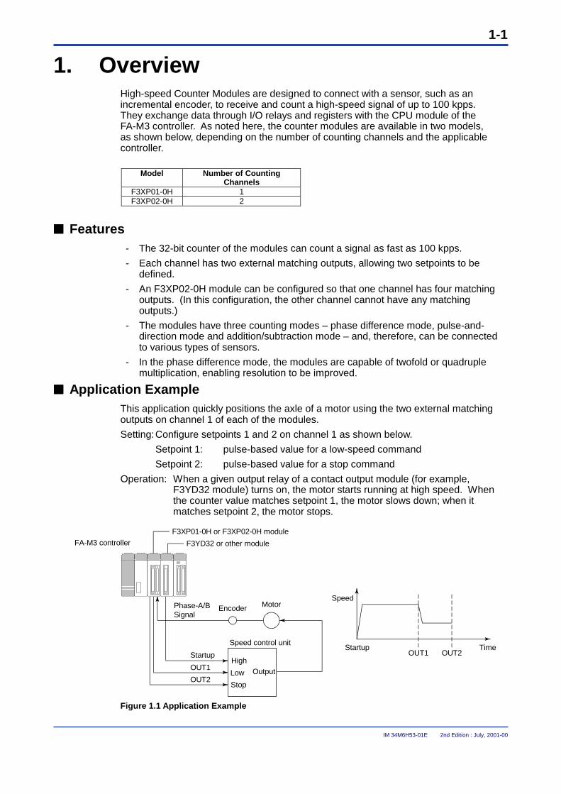
1. OverviewHigh-speed Counter Modules are designed to connect with a sensor, such as anincremental encoder, to receive and count a high-speed signal of up to 100 kpps.They exchange data through I/O relays and registers with the CPU module of theFA-M3 controller. As noted here, the counter modules are available in two models,as shown below, depending on the number of counting channels and the applicablecontroller.
Model Number of CountingChannels
F3XP01-0H 1F3XP02-0H 2
���� Features- The 32-bit counter of the modules can count a signal as fast as 100 kpps.
- Each channel has two external matching outputs, allowing two setpoints to bedefined.
- An F3XP02-0H module can be configured so that one channel has four matchingoutputs. (In this configuration, the other channel cannot have any matchingoutputs.)
- The modules have three counting modes – phase difference mode, pulse-and-direction mode and addition/subtraction mode – and, therefore, can be connectedto various types of sensors.
- In the phase difference mode, the modules are capable of twofold or quadruplemultiplication, enabling resolution to be improved.
���� Application ExampleThis application quickly positions the axle of a motor using the two external matchingoutputs on channel 1 of each of the modules.
Setting:Configure setpoints 1 and 2 on channel 1 as shown below.
Setpoint 1: pulse-based value for a low-speed command
Setpoint 2: pulse-based value for a stop command
Operation: When a given output relay of a contact output module (for example,F3YD32 module) turns on, the motor starts running at high speed. Whenthe counter value matches setpoint 1, the motor slows down; when itmatches setpoint 2, the motor stops.
Phase-A/BSignal
F3XP01-0H or F3XP02-0H module
F3YD32 or other module
Encoder Motor
Startup
OUT1
OUT2
High
Low
Stop
Output
Speed control unitTimeStartup
OUT1 OUT2
Speed
FA-M3 controller
Figure 1.1 Application Example
1-2
IM 34M6H53-01E 2nd Edition : July, 2001-00
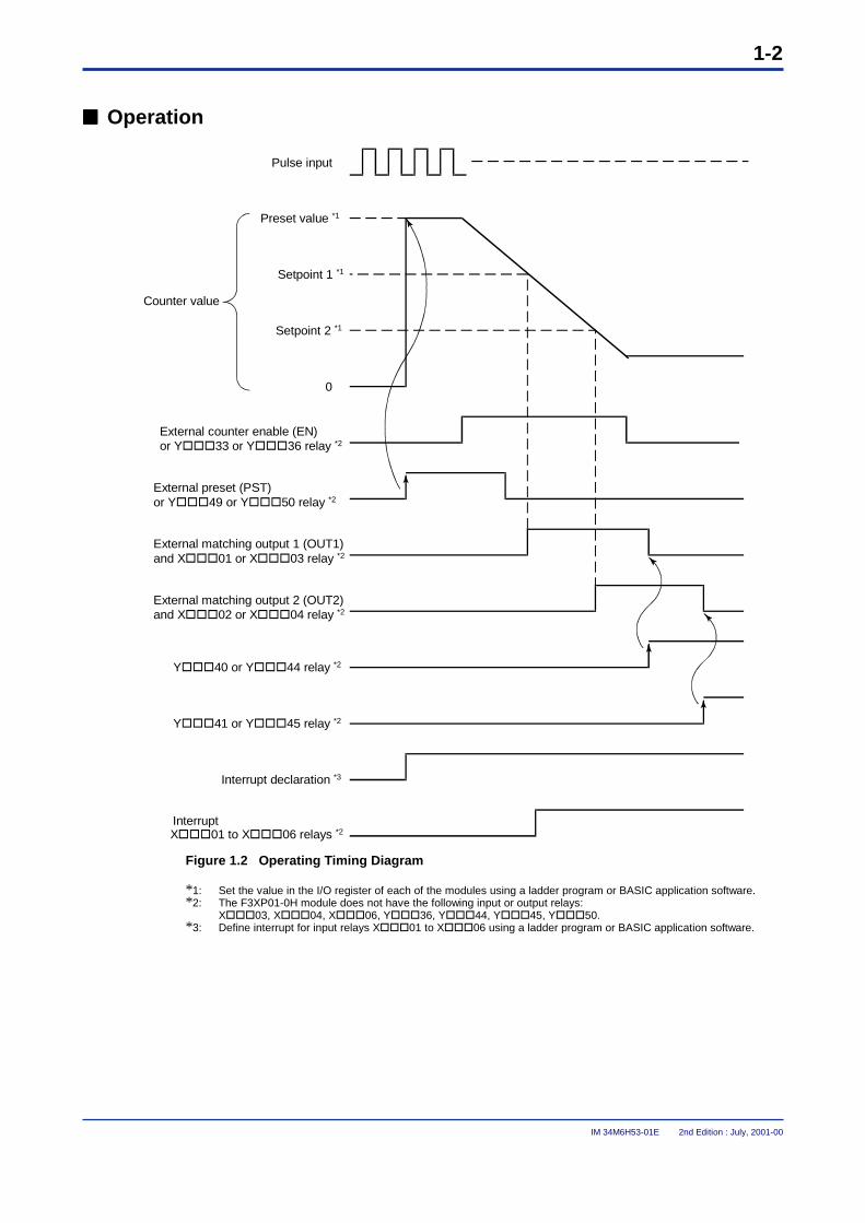
���� Operation
Pulse input
Preset value *1
Setpoint 1 *1
Setpoint 2 *1
0
External counter enable (EN)or Y���33 or Y���36 relay *2
External preset (PST)or Y���49 or Y���50 relay *2
External matching output 1 (OUT1)and X���01 or X���03 relay *2
External matching output 2 (OUT2)and X���02 or X���04 relay *2
Y���40 or Y���44 relay *2
Y���41 or Y���45 relay *2
Interrupt declaration *3
InterruptX���01 to X���06 relays *2
Counter value
Figure 1.2 Operating Timing Diagram
*1: Set the value in the I/O register of each of the modules using a ladder program or BASIC application software.*2: The F3XP01-0H module does not have the following input or output relays:
X���03, X���04, X���06, Y���36, Y���44, Y���45, Y���50.*3: Define interrupt for input relays X���01 to X���06 using a ladder program or BASIC application software.
2-1
IM 34M6H53-01E 2nd Edition : July, 2001-00
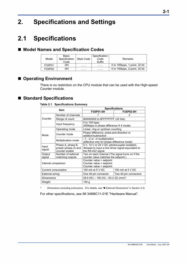
2. Specifications and Settings 2.1 Specifications ���� Model Names and Specification Codes
Model Basic
Specification Code
Style CodeSpecification
Code Suffix
Remarks
F3XP01 -0H …… …… 0 to 100kpps, 1-point, 32 bit F3XP02 -0H …… …… 0 to 100kpps, 2-point, 32 bit
���� Operating Environment There is no restriction on the CPU module that can be used with the High-speed Counter module.
���� Standard Specifications Table 2.1 Specifications Summary
Specifications Item F3XP01-0H F3XP02-0H Number of channels 1 2 Range of count $00000000 to $FFFFFFFF (32 bits) Counter
Input frequency 0 to 100 kpps
(400kpps in phase difference X 4 mode) Operating mode Linear, ring or up/down counting
Counter mode Phase difference, pulse-and-direction or addition/subtraction Mode
Multiplication mode �1, �2 or �4 multiplication (effective only for phase difference mode)
Input signal
Phase A, phase B, preset (phase Z) and counter enable
5 V, 12 V or 24 V DC (photocoupler-isolated). Allowed to input a line driver signal equivalent to the RS-422 signal.
Output signal
Number of external matching outputs
Two on each channel (The signal turns on if the counter value matches the setpoint.)
Internal comparison Counter value > setpoint Counter value = setpoint Counter value < setpoint
Current consumption 100 mA at 5 V DC 150 mA at 5 V DC External wiring One 40-pin connector Two 40-pin connectors Dimensions 28.9 (W) � 100 (H) � 83.2 (D) (mm)* Weight 150 g
*: Dimensions excluding protrusions. (For details, see "� External Dimensions" in Section 2.2) For other specifications, see IM 34M6C11-01E "Hardware Manual”.
2-2
IM 34M6H53-01E 2nd Edition : July, 2001-00
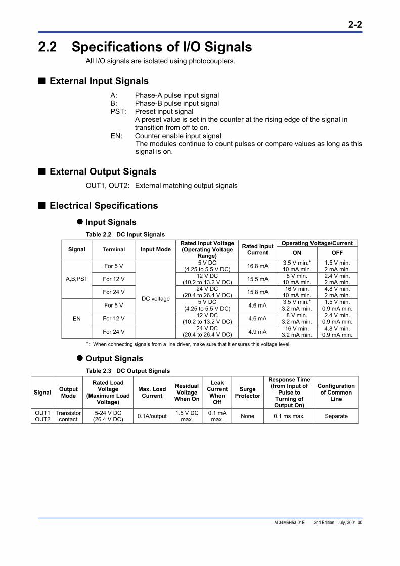
2.2 Specifications of I/O Signals All I/O signals are isolated using photocouplers.
���� External Input Signals A: Phase-A pulse input signal B: Phase-B pulse input signal PST: Preset input signal
A preset value is set in the counter at the rising edge of the signal in transition from off to on.
EN: Counter enable input signal The modules continue to count pulses or compare values as long as this signal is on.
���� External Output Signals OUT1, OUT2: External matching output signals
���� Electrical Specifications ���� Input Signals
Table 2.2 DC Input Signals Operating Voltage/Current
Signal Terminal Input Mode Rated Input Voltage (Operating Voltage
Range) Rated Input
Current ON OFF
For 5 V 5 V DC (4.25 to 5.5 V DC) 16.8 mA 3.5 V min.*
10 mA min. 1.5 V min. 2 mA min.
For 12 V 12 V DC (10.2 to 13.2 V DC) 15.5 mA 8 V min.
10 mA min. 2.4 V min. 2 mA min. A,B,PST
For 24 V 24 V DC (20.4 to 26.4 V DC) 15.8 mA 16 V min.
10 mA min. 4.8 V min. 2 mA min.
For 5 V 5 V DC (4.25 to 5.5 V DC) 4.6 mA 3.5 V min.*
3.2 mA min. 1.5 V min.
0.9 mA min.
For 12 V 12 V DC (10.2 to 13.2 V DC) 4.6 mA 8 V min.
3.2 mA min. 2.4 V min.
0.9 mA min. EN
For 24 V
DC voltage
24 V DC (20.4 to 26.4 V DC) 4.9 mA 16 V min.
3.2 mA min. 4.8 V min.
0.9 mA min. *: When connecting signals from a line driver, make sure that it ensures this voltage level.
���� Output Signals Table 2.3 DC Output Signals
Signal Output Mode
Rated Load Voltage
(Maximum Load Voltage)
Max. Load Current
Residual Voltage
When On
Leak Current When
Off
Surge Protector
Response Time (from Input of
Pulse to Turning of Output On)
Configuration of Common
Line
OUT1 OUT2
Transistor contact
5-24 V DC (26.4 V DC) 0.1A/output 1.5 V DC
max. 0.1 mA max. None 0.1 ms max. Separate
2-3
IM 34M6H53-01E 2nd Edition : July, 2001-00
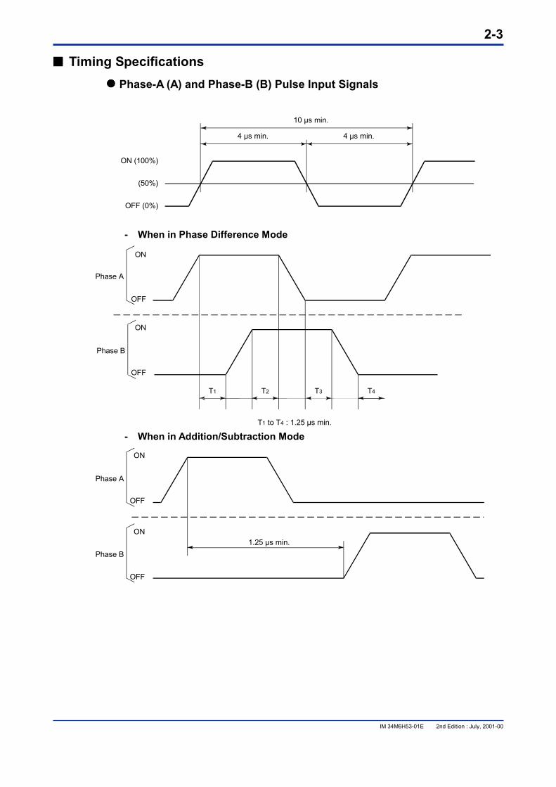
���� Timing Specifications ���� Phase-A (A) and Phase-B (B) Pulse Input Signals
ON (100%)
(50%)
OFF (0%)
10 µs min.
4 µs min.4 µs min.
- When in Phase Difference Mode
ON
OFF
ON
OFF
Phase A
Phase B
T1 T2 T3 T4
T1 to T4 : 1.25 µs min. - When in Addition/Subtraction Mode
ON
OFF
ON
OFF
Phase A
Phase B1.25 µs min.

2-4
IM 34M6H53-01E 2nd Edition : July, 2001-00
- When in Pulse-and-Direction Mode
ON
OFF
ON(Forward)
OFF(Backward)
Phase A
Phase B(Direction)
1.25 µs min.
1.25 µs min.
���� External Counter Enable Input Signal (EN) ON (100%)
(50%)
OFF (0%)
1 ms min. 1 ms min.
���� External Counter Enable Input Signal (EN) and Pulse Input Signal (A/B)
ON
OFF
ON
OFF
Phase A
External counterenable signal
Count Do not count
300 µs min.
300 µs min.
���� External Preset Input Signal (PST)
ON (100%)
(50%)
OFF (0%)
10 µs min.
4 µs min.4 µs min.
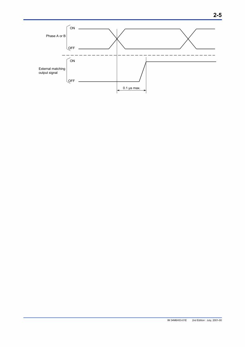
���� External Matching Output Signals (OUT1 and OUT2)
2-5
IM 34M6H53-01E 2nd Edition : July, 2001-00
ON
OFF
ON
OFF
Phase A or B
External matchingoutput signal
0.1 µs max.
2-6
IM 34M6H53-01E 2nd Edition : July, 2001-00
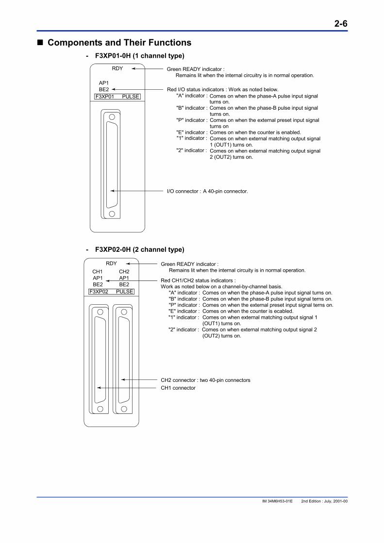
���� Components and Their Functions - F3XP01-0H (1 channel type)
RDY
AP1BE2
F3XP01 PULSE
Green READY indicator : Remains lit when the internal circuitry is in normal operation.
Red I/O status indicators : Work as noted below."A" indicator : Comes on when the phase-A pulse input signal
turns on."B" indicator : Comes on when the phase-B pulse input signal
turns on."P" indicator : Comes on when the external preset input signal
turns on"E" indicator : Comes on when the counter is enabled."1" indicator : Comes on when external matching output signal
1 (OUT1) turns on."2" indicator : Comes on when external matching output signal
2 (OUT2) turns on.
I/O connector : A 40-pin connector.
- F3XP02-0H (2 channel type)
RDY
AP1 AP1BE2 BE2
F3XP02 PULSE
CH1 CH2Green READY indicator : Remains lit when the internal circuity is in normal operation.
CH2 connector : two 40-pin connectorsCH1 connector
Red CH1/CH2 status indicators :Work as noted below on a channel-by-channel basis.
"A" indicator : Comes on when the phase-A pulse input signal turns on."B" indicator : Comes on when the phase-B pulse input signal terns on."P" indicator : Comes on when the external preset input signal terns on."E" indicator : Comes on when the counter is ecabled."1" indicator : Comes on when external matching output signal 1
(OUT1) turns on."2" indicator : Comes on when external matching output signal 2
(OUT2) turns on.
2-7
IM 34M6H53-01E 2nd Edition : July, 2001-00
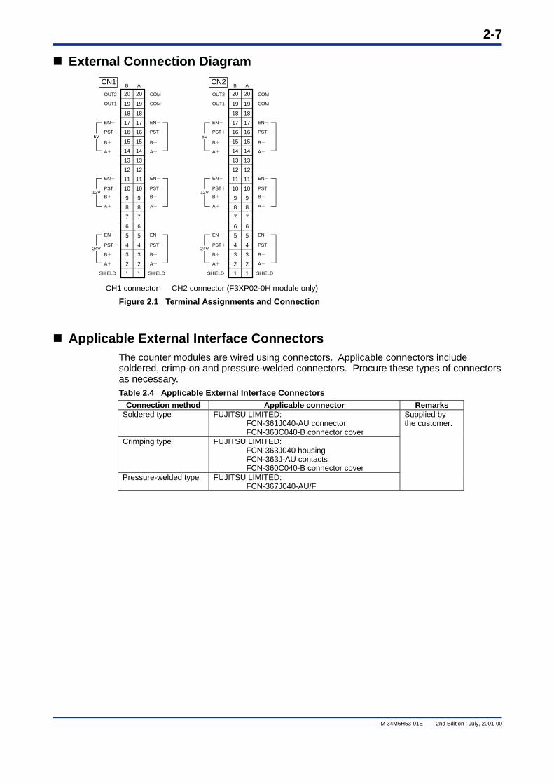
External Connection Diagram
CH1 connector CH2 connector (F3XP02-0H module only)
Figure 2.1 Terminal Assignments and Connection
Applicable External Interface Connectors The counter modules are wired using connectors. Applicable connectors include soldered, crimp-on and pressure-welded connectors. Procure these types of connectors as necessary. Table 2.4 Applicable External Interface Connectors
Connection method Applicable connector Remarks Soldered type FUJITSU LIMITED:
FCN-361J040-AU connector FCN-360C040-B connector cover
Crimping type FUJITSU LIMITED: FCN-363J040 housing FCN-363J-AU contacts FCN-360C040-B connector cover
Pressure-welded type FUJITSU LIMITED: FCN-367J040-AU/F
Supplied by the customer.
CN120
19
18
17
16
15
14
13
12
11
10
9
8
7
6
5
4
3
2
1
20
19
18
17
16
15
14
13
12
11
10
9
8
7
6
5
4
3
2
1
B A
OUT2
OUT1
EN+
PST+
B+
A+
5V
EN+
PST+
B+
A+
EN+
PST+
B+
A+
SHIELD
COM
COM
EN-
PST-
B-
A-
EN-
PST-
B-
A-
EN-
PST-
B-
A-
SHIELD
CN220
19
18
17
16
15
14
13
12
11
10
9
8
7
6
5
4
3
2
1
20
19
18
17
16
15
14
13
12
11
10
9
8
7
6
5
4
3
2
1
B A
OUT2
OUT1
EN+
PST+
B+
A+
5V
EN+
PST+
B+
A+
EN+
PST+
B+
A+
SHIELD
COM
COM
EN-
PST-
B-
A-
EN-
PST-
B-
A-
EN-
PST-
B-
A-
SHIELD
(F3XP02-0Hのみ)
12V 12V
24V 24V
2-8
IM 34M6H53-01E 2nd Edition : July, 2001-00
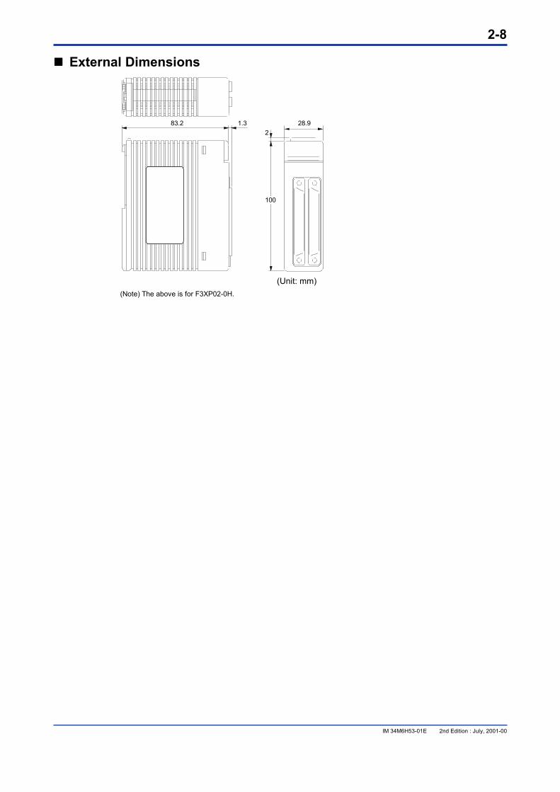
���� External Dimensions
83.2 28.92
1.3
100
(Unit: mm) (Note) The above is for F3XP02-0H.
2-9
IM 34M6H53-01E 2nd Edition : July, 2001-00
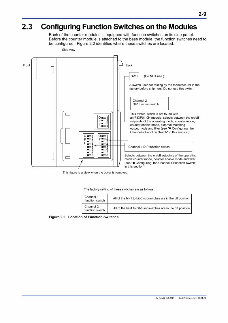
2.3 Configuring Function Switches on the Modules Each of the counter modules is equipped with function switches on its side panel. Before the counter module is attached to the base module, the function switches need to be configured. Figure 2.2 identifies where these switches are located.
1234
12345678
12345678
OFF
OFF
OFF
Side view
SW3 (Do NOT use.)
Back
A switch used for testing by the manufacturer in thefactory before shipment. Do not use this switch.
Channel-2DIP function switch
This switch, which is not found withan F3XP01-0H module, selects between the on/offsetpoints of the operating mode, counter mode,counter enable mode, external matchingoutput mode and filter (see "� Configuring theChannel-2 Function Switch" in this sectiion)
Channel-1 DIP function switch
Selects between the on/off setpoints of the operatingmode counter mode, counter enable mode and filter(see "� Configuring the Channel-1 Function Switch"in this section)
Front
This figure is a view when the cover is removed.
The factory setting of these switches are as follows :
Channel-1function switch
Channel-2function switch
All of the bit-1 to bit-8 subswitches are in the off position.
All of the bit-1 to bit-8 subswitches are in the off position.
Figure 2.2 Location of Function Switches
2-10
IM 34M6H53-01E 2nd Edition : July, 2001-00
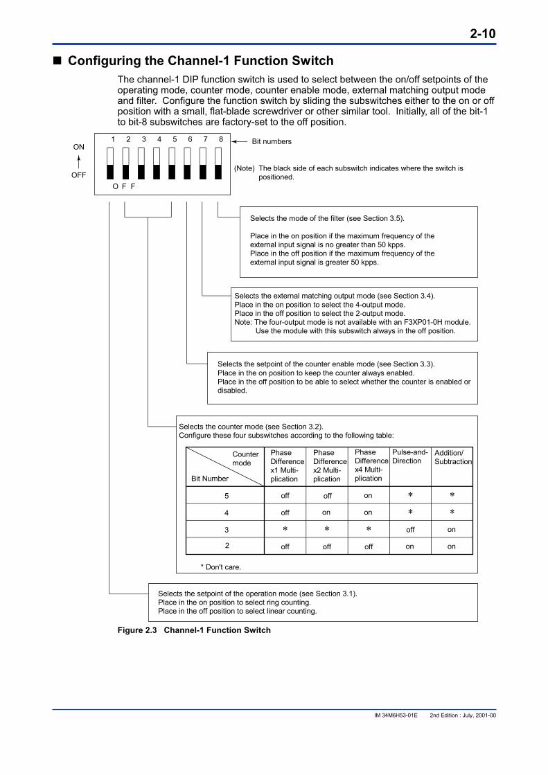
���� Configuring the Channel-1 Function Switch The channel-1 DIP function switch is used to select between the on/off setpoints of the operating mode, counter mode, counter enable mode, external matching output mode and filter. Configure the function switch by sliding the subswitches either to the on or off position with a small, flat-blade screwdriver or other similar tool. Initially, all of the bit-1 to bit-8 subswitches are factory-set to the off position.
1 2 3 4 5 6 7 8
O F F
ON
OFF
Bit numbers
Selects the counter mode (see Section 3.2).Configure these four subswitches according to the following table:
Countermode
Bit Number
5
4
3
2
off
off
off off off
off
off
on
on
on
on on
on* * *** *
*
PhaseDifferencex1 Multi-plication
PhaseDifferencex2 Multi-plication
PhaseDifferencex4 Multi-plication
Pulse-and-Direction
Addition/Subtraction
* Don't care.
Selects the mode of the filter (see Section 3.5).
Place in the on position if the maximum frequency of theexternal input signal is no greater than 50 kpps.Place in the off position if the maximum frequency of theexternal input signal is greater 50 kpps.
Selects the external matching output mode (see Section 3.4).Place in the on position to select the 4-output mode.Place in the off position to select the 2-output mode.Note: The four-output mode is not available with an F3XP01-0H module. Use the module with this subswitch always in the off position.
Selects the setpoint of the counter enable mode (see Section 3.3).Place in the on position to keep the counter always enabled.Place in the off position to be able to select whether the counter is enabled ordisabled.
Selects the setpoint of the operation mode (see Section 3.1).Place in the on position to select ring counting.Place in the off position to select linear counting.
(Note) The black side of each subswitch indicates where the switch ispositioned.
Figure 2.3 Channel-1 Function Switch
2-11
IM 34M6H53-01E 2nd Edition : July, 2001-00
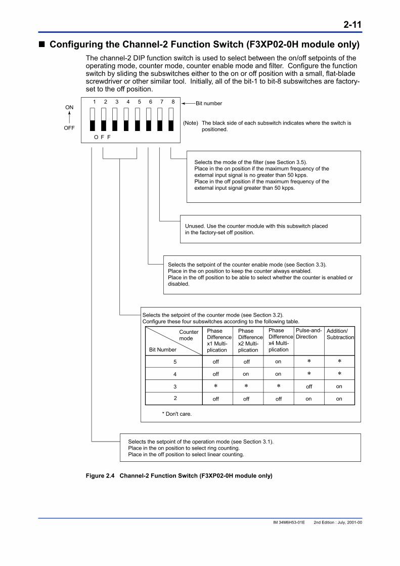
���� Configuring the Channel-2 Function Switch (F3XP02-0H module only) The channel-2 DIP function switch is used to select between the on/off setpoints of the operating mode, counter mode, counter enable mode and filter. Configure the function switch by sliding the subswitches either to the on or off position with a small, flat-blade screwdriver or other similar tool. Initially, all of the bit-1 to bit-8 subswitches are factory-set to the off position.
1 2 3 4 5 6 7 8
O F F
ON
OFF
Bit number
Selects the setpoint of the counter mode (see Section 3.2).Configure these four subswitches according to the following table.
5
4
3
2
off
off
off off off
off
off
on
on
on
on on
on* * *** *
*
* Don't care.
Unused. Use the counter module with this subswitch placedin the factory-set off position.
Selects the mode of the filter (see Section 3.5).Place in the on position if the maximum frequency of theexternal input signal is no greater than 50 kpps.Place in the off position if the maximum frequency of theexternal input signal greater than 50 kpps.
Selects the setpoint of the counter enable mode (see Section 3.3).Place in the on position to keep the counter always enabled.Place in the off position to be able to select whether the counter is enabled ordisabled.
Countermode
Bit Number
PhaseDifferencex1 Multi-plication
PhaseDifferencex2 Multi-plication
PhaseDifferencex4 Multi-plication
Pulse-and-Direction
Addition/Subtraction
Selects the setpoint of the operation mode (see Section 3.1).Place in the on position to select ring counting.Place in the off position to select linear counting.
(Note) The black side of each subswitch indicates where the switch ispositioned.
Figure 2.4 Channel-2 Function Switch (F3XP02-0H module only)
2-12
IM 34M6H53-01E 2nd Edition : July, 2001-00
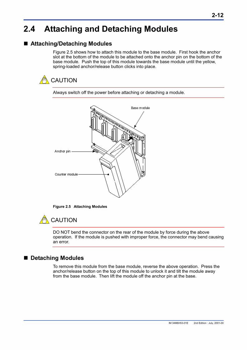
2.4 Attaching and Detaching Modules ���� Attaching/Detaching Modules
Figure 2.5 shows how to attach this module to the base module. First hook the anchor slot at the bottom of the module to be attached onto the anchor pin on the bottom of the base module. Push the top of this module towards the base module until the yellow, spring-loaded anchor/release button clicks into place.
CAUTION
Always switch off the power before attaching or detaching a module.
Figure 2.5 Attaching Modules
CAUTION
DO NOT bend the connector on the rear of the module by force during the above operation. If the module is pushed with improper force, the connector may bend causing an error.
���� Detaching Modules To remove this module from the base module, reverse the above operation. Press the anchor/release button on the top of this module to unlock it and tilt the module away from the base module. Then lift the module off the anchor pin at the base.
2-13
IM 34M6H53-01E 2nd Edition : July, 2001-00
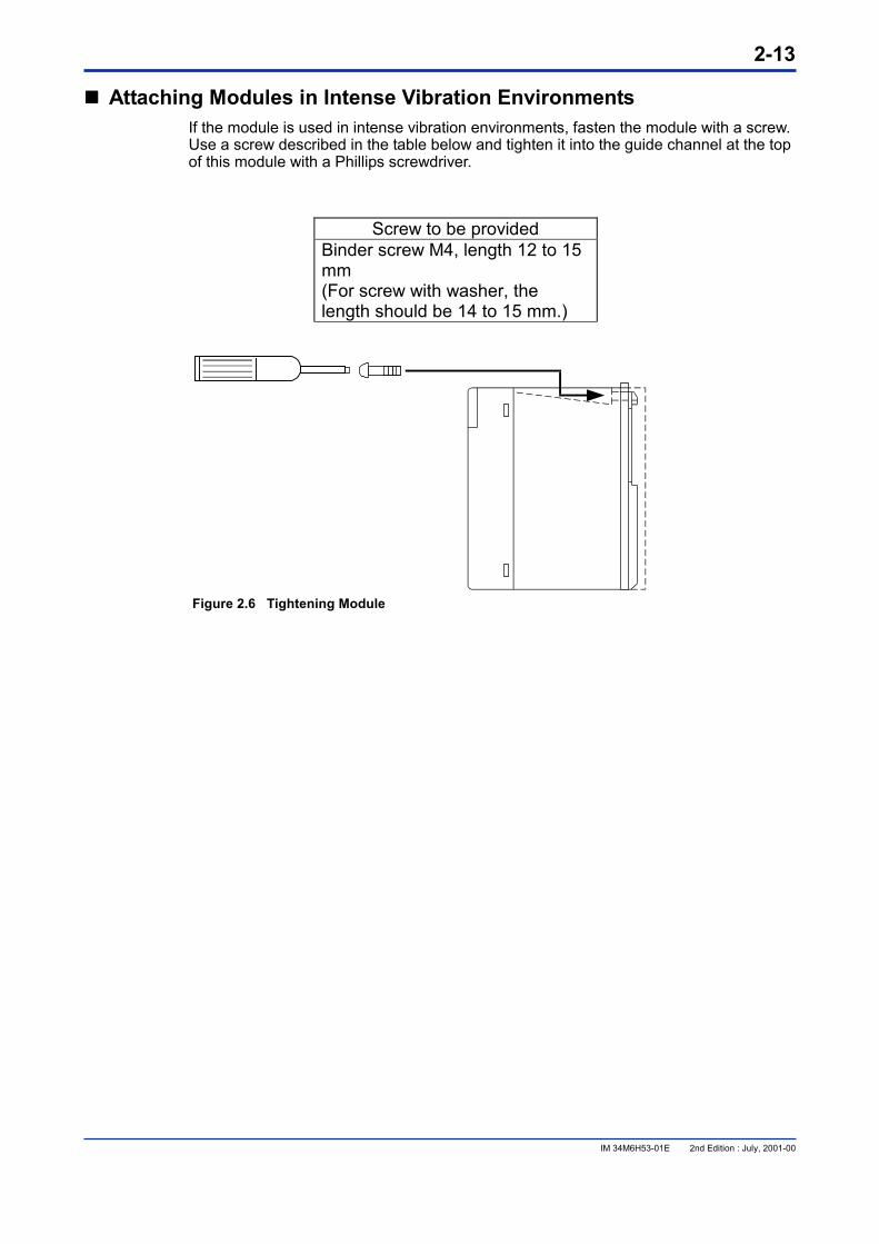
���� Attaching Modules in Intense Vibration Environments If the module is used in intense vibration environments, fasten the module with a screw. Use a screw described in the table below and tighten it into the guide channel at the top of this module with a Phillips screwdriver.
Screw to be provided Binder screw M4, length 12 to 15
mm (For screw with washer, the length should be 14 to 15 mm.)
Figure 2.6 Tightening Module
2-14
IM 34M6H53-01E 2nd Edition : July, 2001-00
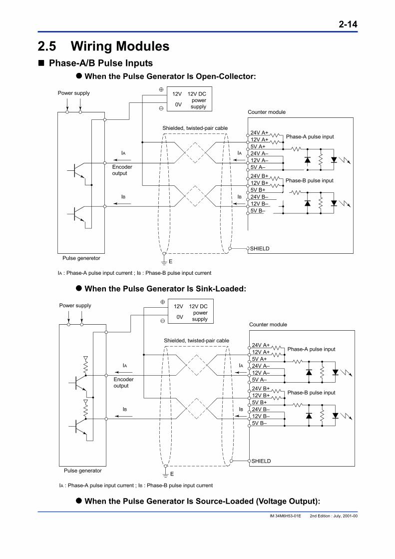
2.5 Wiring Modules ���� Phase-A/B Pulse Inputs
���� When the Pulse Generator Is Open-Collector:
24V A+Phase-A pulse input12V A+
5V A+24V A–12V A–5V A–24V B+12V B+5V B+24V B–12V B–5V B–
SHIELD
12V
0V
12V DCpowersupply
Power supply
IA
IB
IA
IB
Encoderoutput
Shielded, twisted-pair cable
Pulse generetor
IA : Phase-A pulse input current ; IB : Phase-B pulse input current
Counter module
E
Phase-B pulse input
���� When the Pulse Generator Is Sink-Loaded:
24V A+Phase-A pulse input12V A+
5V A+24V A–12V A–5V A–24V B+
Phase-B pulse input12V B+5V B+24V B–12V B–5V B–
SHIELD
12V
0V
12V DCpowersupply
Power supply
IA
IB
IA
IB
Encoderoutput
Shielded, twisted-pair cable
Pulse generator
IA : Phase-A pulse input current ; IB : Phase-B pulse input current
Counter module
E
���� When the Pulse Generator Is Source-Loaded (Voltage Output):
2-15
IM 34M6H53-01E 2nd Edition : July, 2001-00
24V A+Phase-A pulse input12V A+
5V A+24V A–12V A–5V A–24V B+
Phase-B pulse input12V B+5V B+24V B–12V B–5V B–
SHIELD
5V
0V
5V DCpowersupply
IA
IB
Shielded, twisted-pair cable
Pulse generator
IA : phase-A pulse input current ; IB : phase-B pulse input current
Counter module
E
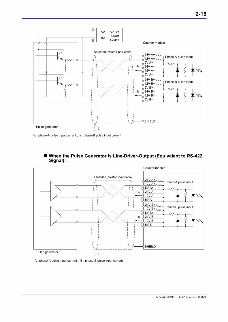
���� When the Pulse Generator Is Line-Driver-Output (Equivalent to RS-422 Signal):
24V A+Phase-A pulse input12V A+
5V A+24V A–12V A–5V A–24V B+
Phase-B pulse input12V B+5V B+24V B–12V B–5V B–
SHIELD
IA
IB
Shielded, twisted-pair cable
Pulse generator
IA : phase-A pulse input current ; IB : phase-B pulse input current
Counter module
E
2-16
IM 34M6H53-01E 2nd Edition : July, 2001-00
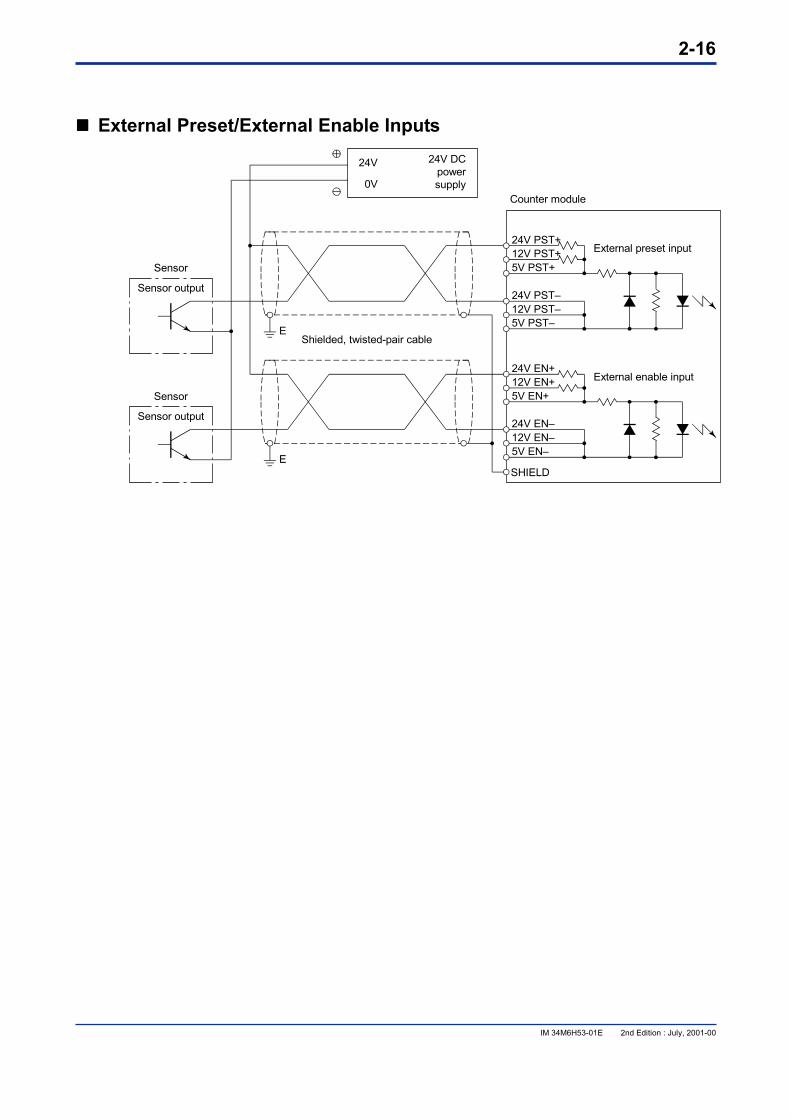
���� External Preset/External Enable Inputs
24V PST+External preset input12V PST+
5V PST+
24V PST–12V PST–5V PST–
24V EN+External enable input12V EN+
5V EN+
24V EN–12V EN–5V EN–
SHIELD
24V
0V
24V DCpowersupply
Shielded, twisted-pair cable
Sensor output
Sensor
Sensor output
Sensor
Counter module
E
E
2-17
IM 34M6H53-01E 2nd Edition : July, 2001-00
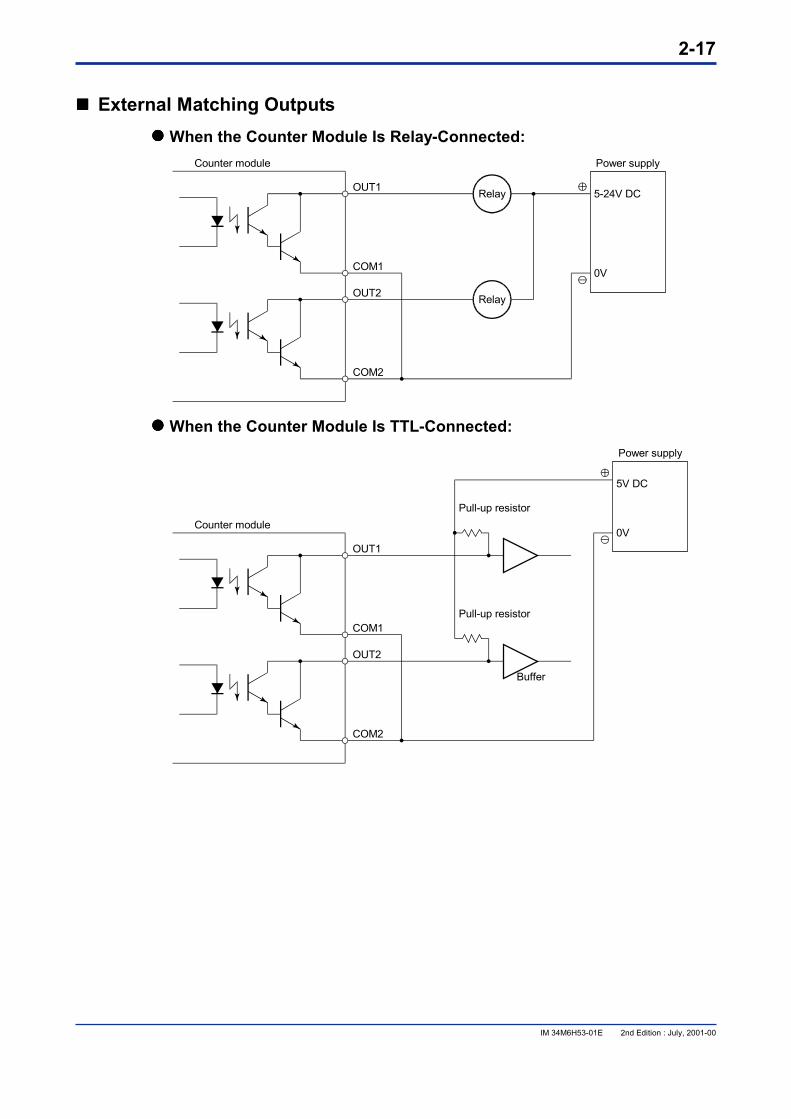
���� External Matching Outputs ���� When the Counter Module Is Relay-Connected:
Power supply
OUT1
COM1
OUT2
COM2
5-24V DC
0V
Counter module
Relay
Relay
���� When the Counter Module Is TTL-Connected: Power supply
OUT1
COM1
OUT2
COM2
5V DC
Pull-up resistor
Pull-up resistor
Buffer
0VCounter module
2-18
IM 34M6H53-01E 2nd Edition : July, 2001-00
���� Notes on Wiring ���� Connection to Input Terminals
Separate input terminals are provided depending on the level of the signal voltage. Connecting a cable to an input terminal with the wrong voltage may result in not only a failure of the module to operate properly but also damage to the module.
���� Cables for Wiring Use shielded, twisted-pair cables. Connect the end of the cable’s shielding wire on the side of the counter module to the module’s SHIELD terminal.
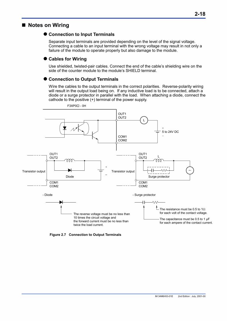
���� Connection to Output Terminals Wire the cables to the output terminals in the correct polarities. Reverse-polarity wiring will result in the output load being on. If any inductive load is to be connected, attach a diode or a surge protector in parallel with the load. When attaching a diode, connect the cathode to the positive (+) terminal of the power supply.
�
5 to 24V DC�
F3XP0� - 0H
OUT1OUT2
OUT1OUT2
COM1COM2
COM1COM2
Transistor output
Diode
L
L
�
–
OUT1OUT2
COM1COM2
Transistor output
Surge protector
- Diode - Surge protector
The resistance must be 0.5 to 1�for each volt of the contact voltage.
The capacitance must be 0.5 to 1 µFfor each ampere of the contact current.
The reverse voltage must be no less than10 times the circuit voltage andthe forward current must be no less thantwice the load current.
Figure 2.7 Connection to Output Terminals
2-19
IM 34M6H53-01E 2nd Edition : July, 2001-00
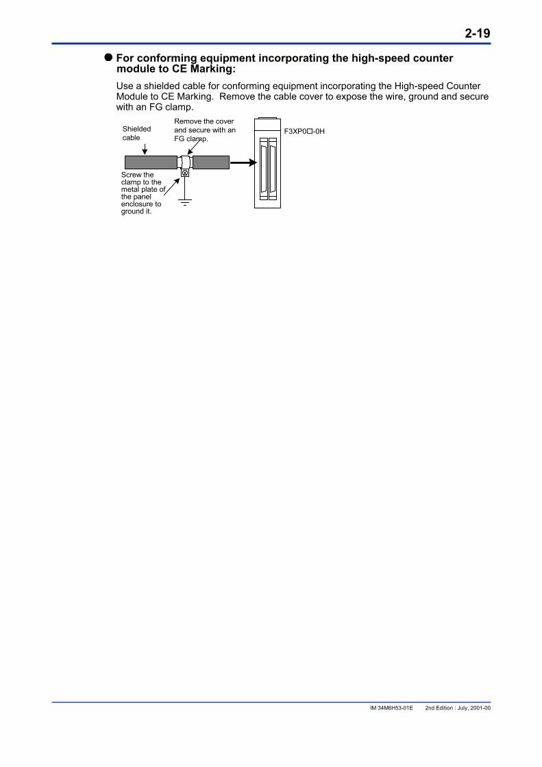
���� For conforming equipment incorporating the high-speed counter module to CE Marking: Use a shielded cable for conforming equipment incorporating the High-speed Counter Module to CE Marking. Remove the cable cover to expose the wire, ground and secure with an FG clamp.
F3XP0�-0HRemove the coverand secure with anFG clamp.
Shieldedcable
Screw theclamp to themetal plate ofthe panelenclosure toground it.

Blank Page

3-1
IM 34M6H53-01E 2nd Edition : July, 2001-00
3. Functions of the Function Switch 3.1 Operation Mode
There are two types of operation mode: (1) Linear mode (2) Ring mode
The operation mode is set by bit number 1 of the function switch. See Section 2.3.
Linear Operation In linear operation, the counter value varies between $00000000 and $FFFFFFFF ($ denotes a hexadecimal number). When the counter value is $00000000 and a down-pulse is entered, underflow occurs and the counter value $00000000 remains unchanged. When the counter value is $FFFFFFFF and an up-pulse is input, overflow occurs and the counter value $FFFFFFFF remains unchanged. An interrupt can be generated when a counter overflow/underflow occurs. When the operation mode is set to Linear operation, use the initial value $FFFFFFFF as the maximum ring value. When a value other than $FFFFFFFF is set as the maximum ring value, either reset the module or set it to $FFFFFFFF again.
Counter value $00000000 $FFFFFFFF
Underflow
UP
DOWNOverflow
Figure 3.1 Linear Operation
When an underflow or overflow occurs, the counter overflow/underflow input relay becomes 1 (ON). To determine whether a counter overflow or underflow has occurred, read the input relay status corresponding to each channel as shown in Table 3.1.
Table 3.1 Input Relay for Counter Overflow/Underflow Input Relay Number*1
Relay Contents Relay Status = 1 (ON)
Relay Status = 0 (OFF)
X 05 Counter overflow/underflow for channel 1 Occurred Not occurred X 06*2 Counter overflow/underflow for channel 2 Occurred Not occurred
*1: is the slot number where the module is installed. *2: Not applicable to F3XP01-0H.
3-2
IM 34M6H53-01E 2nd Edition : July, 2001-00
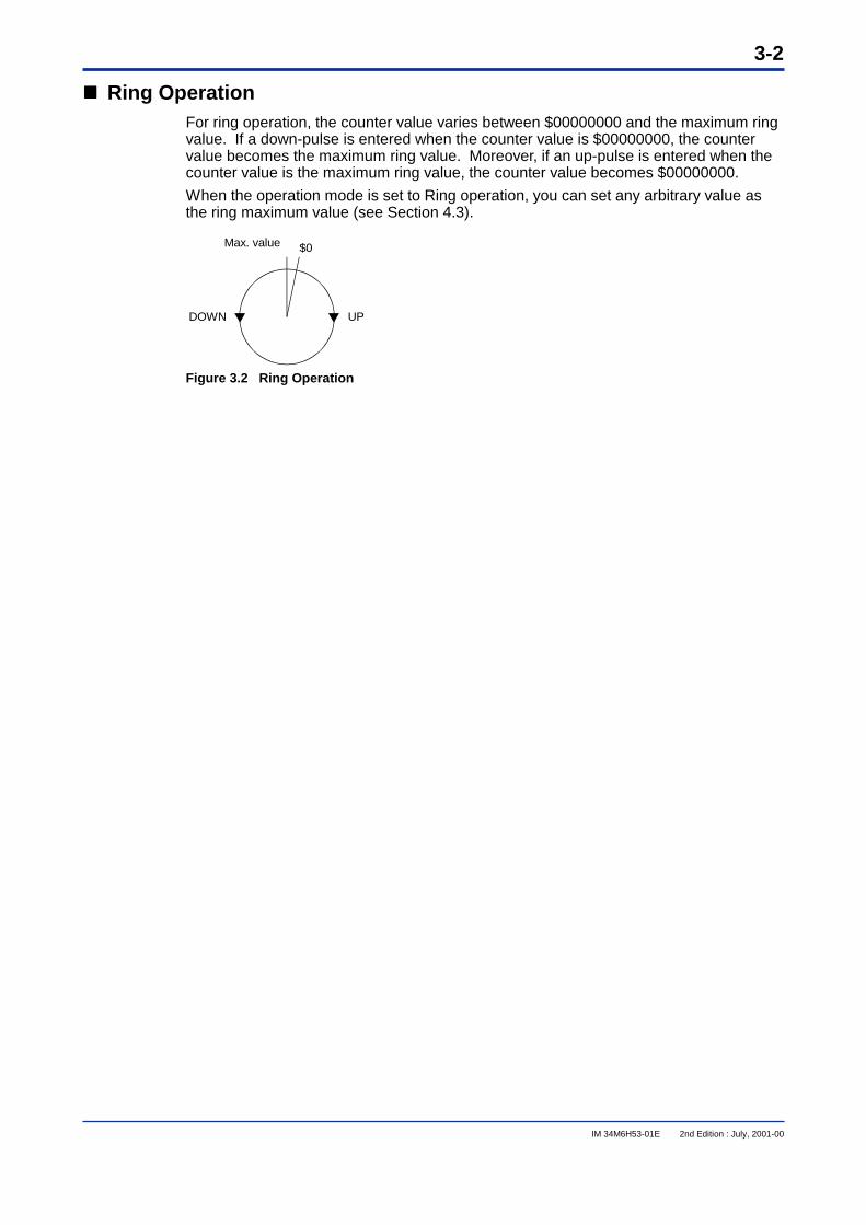
���� Ring OperationFor ring operation, the counter value varies between $00000000 and the maximum ringvalue. If a down-pulse is entered when the counter value is $00000000, the countervalue becomes the maximum ring value. Moreover, if an up-pulse is entered when thecounter value is the maximum ring value, the counter value becomes $00000000.
When the operation mode is set to Ring operation, you can set any arbitrary value asthe ring maximum value (see Section 4.3).
$0
DOWN UP
Max. value
Figure 3.2 Ring Operation
3-3
IM 34M6H53-01E 2nd Edition : July, 2001-00
3.2 Counter ModesThere are five types of counter mode:
- Phase difference x 1 mode
- Phase difference x 2 mode
- Phase difference x 4 mode
- Pulse-and-direction mode
- Addition/subtraction mode
The counter mode is set by bit numbers 2, 3, 4, 5 of the function switch. See Section2.3 of this manual.
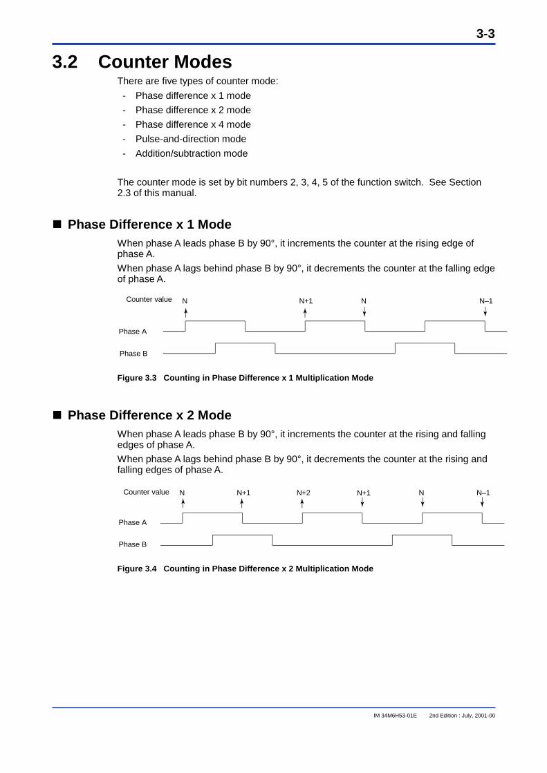
���� Phase Difference x 1 ModeWhen phase A leads phase B by 90°, it increments the counter at the rising edge ofphase A.
When phase A lags behind phase B by 90°, it decrements the counter at the falling edgeof phase A.
Phase A
Phase B
Counter value NN N+1 N–1
Figure 3.3 Counting in Phase Difference x 1 Multiplication Mode
���� Phase Difference x 2 ModeWhen phase A leads phase B by 90°, it increments the counter at the rising and fallingedges of phase A.
When phase A lags behind phase B by 90°, it decrements the counter at the rising andfalling edges of phase A.
Phase A
Phase B
Counter value NN N+1 N+2 N–1N+1
Figure 3.4 Counting in Phase Difference x 2 Multiplication Mode
3-4
IM 34M6H53-01E 2nd Edition : July, 2001-00
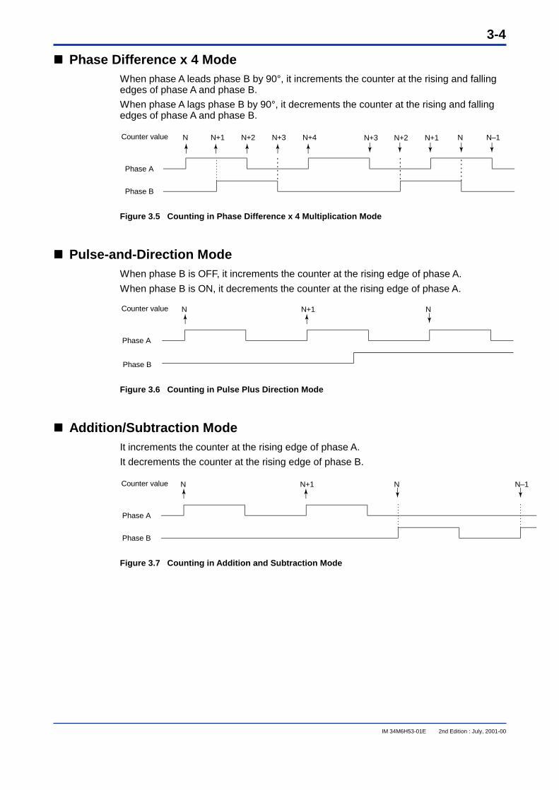
���� Phase Difference x 4 ModeWhen phase A leads phase B by 90°, it increments the counter at the rising and fallingedges of phase A and phase B.
When phase A lags phase B by 90°, it decrements the counter at the rising and fallingedges of phase A and phase B.
Phase A
Phase B
Counter value NN N+1 N+2 N+3 N+4 N–1N+3 N+2 N+1
Figure 3.5 Counting in Phase Difference x 4 Multiplication Mode
���� Pulse-and-Direction ModeWhen phase B is OFF, it increments the counter at the rising edge of phase A.
When phase B is ON, it decrements the counter at the rising edge of phase A.
Phase A
Phase B
Counter value NN N+1
Figure 3.6 Counting in Pulse Plus Direction Mode
���� Addition/Subtraction ModeIt increments the counter at the rising edge of phase A.
It decrements the counter at the rising edge of phase B.
Phase A
Phase B
Counter value NN N+1 N–1
Figure 3.7 Counting in Addition and Subtraction Mode
3-5
IM 34M6H53-01E 2nd Edition : July, 2001-00
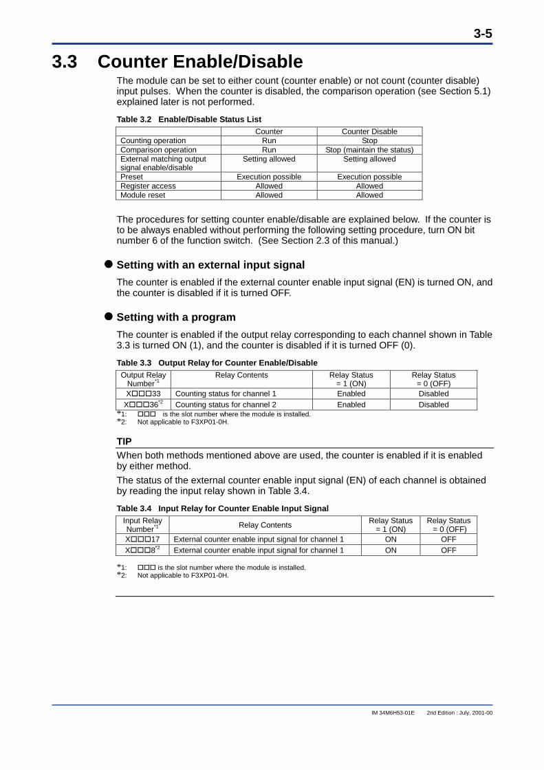
3.3 Counter Enable/DisableThe module can be set to either count (counter enable) or not count (counter disable)input pulses. When the counter is disabled, the comparison operation (see Section 5.1)explained later is not performed.
Table 3.2 Enable/Disable Status ListCounter Counter Disable
Counting operation Run StopComparison operation Run Stop (maintain the status)External matching outputsignal enable/disable
Setting allowed Setting allowed
Preset Execution possible Execution possibleRegister access Allowed AllowedModule reset Allowed Allowed
The procedures for setting counter enable/disable are explained below. If the counter isto be always enabled without performing the following setting procedure, turn ON bitnumber 6 of the function switch. (See Section 2.3 of this manual.)
���� Setting with an external input signal
The counter is enabled if the external counter enable input signal (EN) is turned ON, andthe counter is disabled if it is turned OFF.
���� Setting with a program
The counter is enabled if the output relay corresponding to each channel shown in Table3.3 is turned ON (1), and the counter is disabled if it is turned OFF (0).
Table 3.3 Output Relay for Counter Enable/DisableOutput Relay
Number*1Relay Contents Relay Status
= 1 (ON)Relay Status
= 0 (OFF)X���33 Counting status for channel 1 Enabled Disabled
X���36*2 Counting status for channel 2 Enabled Disabled*1: ����is the slot number where the module is installed.*2: Not applicable to F3XP01-0H.
TIPWhen both methods mentioned above are used, the counter is enabled if it is enabledby either method.
The status of the external counter enable input signal (EN) of each channel is obtainedby reading the input relay shown in Table 3.4.
Table 3.4 Input Relay for Counter Enable Input SignalInput RelayNumber*1 Relay Contents Relay Status
= 1 (ON)Relay Status
= 0 (OFF)X���17 External counter enable input signal for channel 1 ON OFFX���8*2 External counter enable input signal for channel 1 ON OFF
*1:� ��� is the slot number where the module is installed.*2: Not applicable to F3XP01-0H.
3-6
IM 34M6H53-01E 2nd Edition : July, 2001-00
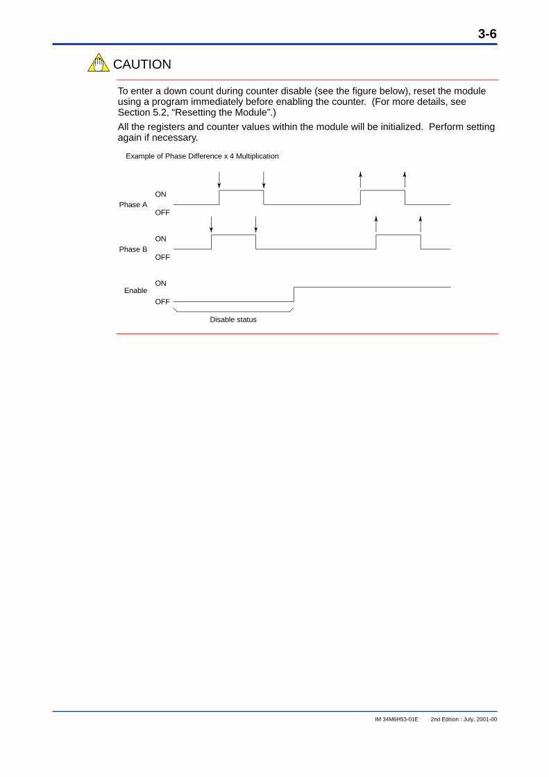
CAUTION
To enter a down count during counter disable (see the figure below), reset the moduleusing a program immediately before enabling the counter. (For more details, seeSection 5.2, “Resetting the Module”.)
All the registers and counter values within the module will be initialized. Perform settingagain if necessary.
Phase A
Phase B
Enable
Example of Phase Difference x 4 Multiplication
Disable status
ON
OFF
ON
OFF
ON
OFF
3-7
IM 34M6H53-01E 2nd Edition : July, 2001-00
3.4 External Matching Output Mode
CAUTION
Only the external matching output 2-point mode can be used for F3XP01-0H. Externalmatching output 4-point mode cannot be used.
There are two types of external matching output mode: external matching output 2-pointmode and external matching output 4-point mode. In this module, each channel has twoexternal matching outputs. External matching output of channel 1 can be converted into4-point mode by using the external matching outputs of channel 2 for channel 1.
���� External matching output 2-point mode
As per the original function of this module, the external matching output for everychannel has two points.
���� External matching output 4-point mode
This can be used in F3XP02-0H. The External matching output for channel 1 is 4-pointand that for channel 2 is 0-point (Nil).
In addition to the counting operation, channel 1 performs the comparison operation withfour set points and it has a 4-point external matching output. The data position numberof the set point, the input relay number showing the result of the comparison operation,and the output relay number for performing reset or enable/disable for the two pointsadded to channel 1 are the same as that for the original channel 2. Counting operationfor channel 2 is still performed (counter value can also be read) but the comparisonoperation and external matching output for channel 2 are absent.
To set the external matching output 4-point mode, turn on bit number 7 of the functionswitch for channel 1. (See Section 2.3).
3.5 FilterThe filter removes noise in the external input signals (phase A, phase B, preset andenable of each channel).
For proper functioning of the filter, change the characteristics of the filter using bitnumber 8 of the function switch for each channel. When the maximum frequency ofphase A, phase B or external preset signal exceeds 50 kpps, bit number 8 is turned OFFand when it is below 50 kpps, bit number 8 is turned ON. (See Section 2.3).

Blank Page
4-1
IM 34M6H53-01E 2nd Edition : July, 2001-00
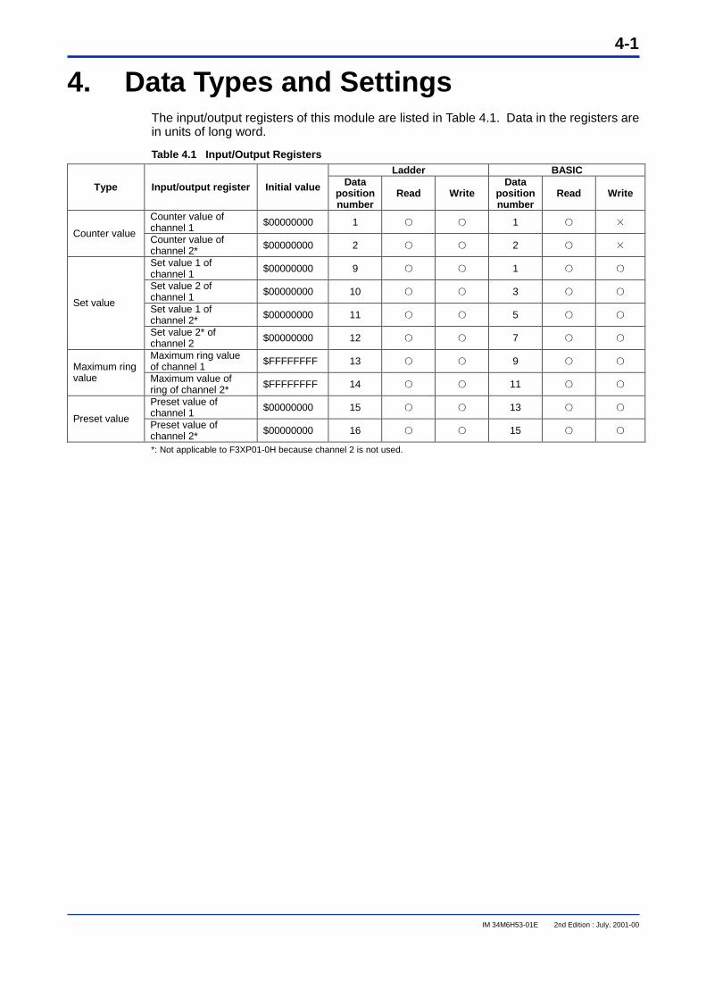
4. Data Types and SettingsThe input/output registers of this module are listed in Table 4.1. Data in the registers arein units of long word.
Table 4.1 Input/Output RegistersLadder BASIC
Type Input/output register Initial value Datapositionnumber
Read WriteData
positionnumber
Read Write
Counter value ofchannel 1 $00000000 1 ○ ○ 1 ○ ×
Counter valueCounter value ofchannel 2* $00000000 2 ○ ○ 2 ○ ×
Set value 1 ofchannel 1 $00000000 9 ○ ○ 1 ○ ○
Set value 2 ofchannel 1 $00000000 10 ○ ○ 3 ○ ○
Set value 1 ofchannel 2* $00000000 11 ○ ○ 5 ○ ○
Set value
Set value 2* ofchannel 2 $00000000 12 ○ ○ 7 ○ ○
Maximum ring valueof channel 1 $FFFFFFFF 13 ○ ○ 9 ○ ○Maximum ring
value Maximum value ofring of channel 2* $FFFFFFFF 14 ○ ○ 11 ○ ○
Preset value ofchannel 1 $00000000 15 ○ ○ 13 ○ ○
Preset valuePreset value ofchannel 2* $00000000 16 ○ ○ 15 ○ ○
*: Not applicable to F3XP01-0H because channel 2 is not used.
4-2
IM 34M6H53-01E 2nd Edition : July, 2001-00
4.1 Counter Value
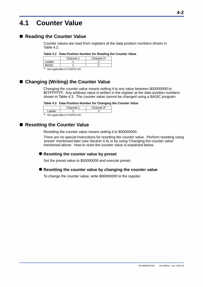
���� Reading the Counter ValueCounter values are read from registers at the data position numbers shown inTable 4.2.
Table 4.2 Data Position Number for Reading the Counter ValueChannel 1 Channel 2*
Ladder 1 2BASIC 1 2
*: Not applicable to F3XP01-0H.
���� Changing (Writing) the Counter ValueChanging the counter value means setting it to any value between $00000000 to$FFFFFFFF. Any arbitrary value is written in the register at the data position numbersshown in Table 4.3. The counter value cannot be changed using a BASIC program.
Table 4.3 Data Position Number for Changing the Counter ValueChannel 1 Channel 2*
Ladder 1 2*: Not applicable to F3XP01-0H.
���� Resetting the Counter ValueResetting the counter value means setting it to $00000000.
There are no special instructions for resetting the counter value. Perform resetting using'preset' mentioned later (see Section 4.4) or by using 'Changing the counter value'mentioned above. How to reset the counter value is explained below.
���� Resetting the counter value by preset
Set the preset value to $00000000 and execute preset.
���� Resetting the counter value by changing the counter value
To change the counter value, write $00000000 to the register.
4-3
IM 34M6H53-01E 2nd Edition : July, 2001-00
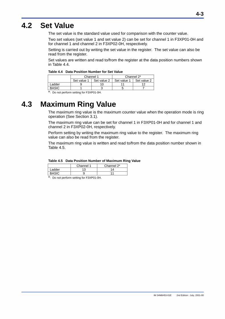
4.2 Set ValueThe set value is the standard value used for comparison with the counter value.
Two set values (set value 1 and set value 2) can be set for channel 1 in F3XP01-0H andfor channel 1 and channel 2 in F3XP02-0H, respectively.
Setting is carried out by writing the set value in the register. The set value can also beread from the register.
Set values are written and read to/from the register at the data position numbers shownin Table 4.4.
Table 4.4 Data Position Number for Set ValueChannel 1 Channel 2*
Set value 1 Set value 2 Set value 1 Set value 2Ladder 9 10 11 12BASIC 1 3 5 7
*: Do not perform setting for F3XP01-0H.
4.3 Maximum Ring ValueThe maximum ring value is the maximum counter value when the operation mode is ringoperation (See Section 3.1).
The maximum ring value can be set for channel 1 in F3XP01-0H and for channel 1 andchannel 2 in F3XP02-0H, respectively.
Perform setting by writing the maximum ring value to the register. The maximum ringvalue can also be read from the register.
The maximum ring value is written and read to/from the data position number shown inTable 4.5.
Table 4.5 Data Position Number of Maximum Ring ValueChannel 1 Channel 2*
Ladder 13 14BASIC 9 11
*: Do not perform setting for F3XP01-0H.
4-4
IM 34M6H53-01E 2nd Edition : July, 2001-00
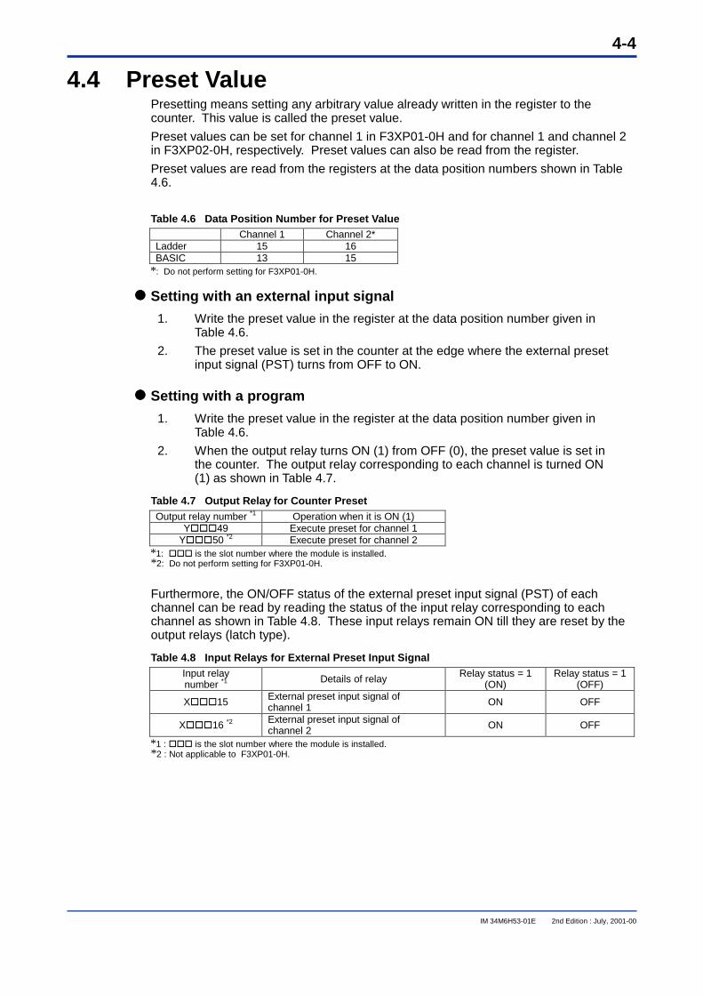
4.4 Preset ValuePresetting means setting any arbitrary value already written in the register to thecounter. This value is called the preset value.
Preset values can be set for channel 1 in F3XP01-0H and for channel 1 and channel 2in F3XP02-0H, respectively. Preset values can also be read from the register.
Preset values are read from the registers at the data position numbers shown in Table4.6.
Table 4.6 Data Position Number for Preset ValueChannel 1 Channel 2*
Ladder 15 16BASIC 13 15
*: Do not perform setting for F3XP01-0H.
���� Setting with an external input signal
1. Write the preset value in the register at the data position number given inTable 4.6.
2. The preset value is set in the counter at the edge where the external presetinput signal (PST) turns from OFF to ON.
���� Setting with a program
1. Write the preset value in the register at the data position number given inTable 4.6.
2. When the output relay turns ON (1) from OFF (0), the preset value is set inthe counter. The output relay corresponding to each channel is turned ON(1) as shown in Table 4.7.
Table 4.7 Output Relay for Counter PresetOutput relay number *1 Operation when it is ON (1)
Y���49 Execute preset for channel 1Y���50 *2 Execute preset for channel 2
*1: ��� is the slot number where the module is installed.*2: Do not perform setting for F3XP01-0H.
Furthermore, the ON/OFF status of the external preset input signal (PST) of eachchannel can be read by reading the status of the input relay corresponding to eachchannel as shown in Table 4.8. These input relays remain ON till they are reset by theoutput relays (latch type).
Table 4.8 Input Relays for External Preset Input SignalInput relaynumber *1 Details of relay Relay status = 1
(ON)Relay status = 1
(OFF)
X���15 External preset input signal ofchannel 1 ON OFF
X���16 *2 External preset input signal ofchannel 2 ON OFF
*1 : ��� is the slot number where the module is installed.*2 : Not applicable to F3XP01-0H.
5-1
IM 34M6H53-01E 2nd Edition : July, 2001-00
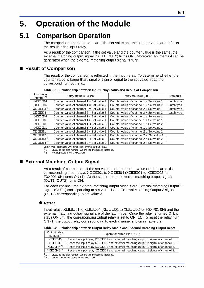
5. Operation of the Module 5.1 Comparison Operation
The comparison operation compares the set value and the counter value and reflects the result in the input relay. As a result of the comparison, if the set value and the counter value is the same, the external matching output signal (OUT1, OUT2) turns ON. Moreover, an interrupt can be generated when the external matching output signal is 'ON'.
Result of Comparison
The result of the comparison is reflected in the input relay. To determine whether the counter value is larger than, smaller than or equal to the set value, read the corresponding input relay.
Table 5.1 Relationship between Input Relay Status and Result of Comparison Input relay number *1 Relay status =1 (ON) Relay status=0 (OFF) Remarks
X 01 Counter value of channel 1 = Set value 1 Counter value of channel 1 ≠ Set value 1 Latch type X 02 Counter value of channel 1 = Set value 2 Counter value of channel 1 ≠ Set value 2 Latch type
X 03 *2 Counter value of channel 2 = Set value 1 Counter value of channel 2 ≠ Set value 1 Latch type X 04 *2 Counter value of channel 2 = Set value 2 Counter value of channel 2 ≠ Set value 2 Latch type X 07 Counter value of channel 1 < Set value 1 Counter value of channel 1 ≥ Set value 1 X 08 Counter value of channel 1 > Set value 1 Counter value of channel 1 ≤ Set value 1 X 09 Counter value of channel 1 < Set value 2 Counter value of channel 1 ≥ Set value 2 X 10 Counter value of channel 1 > Set value 2 Counter value of channel 1 ≤ Set value 2
X 11 *2 Counter value of channel 2 < Set value 1 Counter value of channel 2 ≥ Set value 1 X 12 *2 Counter value of channel 2 > Set value 1 Counter value of channel 2 ≤ Set value 1 X 13 *2 Counter value of channel 2 < Set value 2 Counter value of channel 2 ≥ Set value 2 X 14 *2 Counter value of channel 2 > Set value 2 Counter value of channel 2 ≤ Set value 2
Latch type: Remains ON, until reset by the output relay. *1 : is the slot number where the module is installed. *2 : Not applicable to F3XP01-0H.
External Matching Output Signal
As a result of comparison, if the set value and the counter value are the same, the corresponding input relays X 01 to X 04 (X 01 to X 02 for F3XP01-0H) turns ON (1). At the same time the external matching output signals (OUT1, OUT2) turns ON. For each channel, the external matching output signals are External Matching Output 1 signal (OUT1) corresponding to set value 1 and External Matching Output 2 signal (OUT2) corresponding to set value 2.
Reset Input relays X 01 to X 04 (X 01 to X 02 for F3XP01-0H) and the external matching output signal are of the latch type. Once the relay is turned ON, it stays ON until the corresponding output relay is set to ON (1). To reset the relay, turn ON (1) the output relay corresponding to each channel shown in Table 5.2.
Table 5.2 Relationship between Output Relay Status and External Matching Output Reset Output relay number *1 Operation when it is ON (1)
Y 40 Reset the input relay X 01 and external matching output 1 signal of channel 1. Y 41 Reset the input relay X 02 and external matching output 2 signal of channel 1.
Y 44 *2 Reset the input relay X 03 and external matching output 1 signal of channel 2. Y 45 *2 Reset the input relay X 04 and external matching output 2 signal of channel 2.
*1 : is the slot number where the module is installed. *2 : Do not perform setting for F3XP01-0H.
5-2
IM 34M6H53-01E 2nd Edition : July, 2001-00
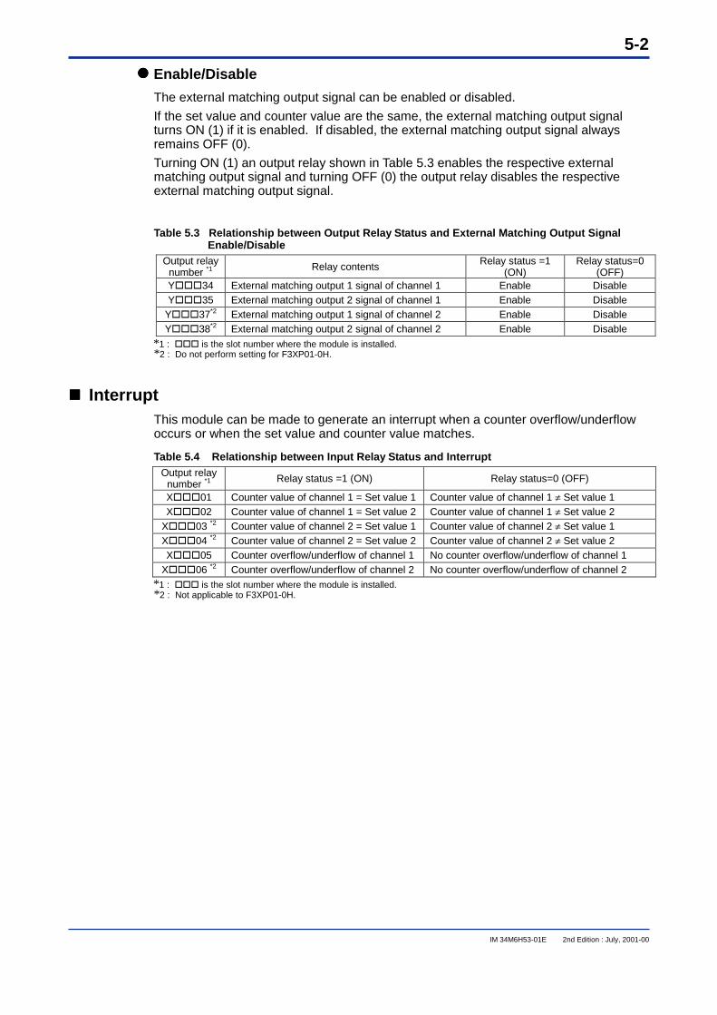
���� Enable/Disable
The external matching output signal can be enabled or disabled.
If the set value and counter value are the same, the external matching output signalturns ON (1) if it is enabled. If disabled, the external matching output signal alwaysremains OFF (0).
Turning ON (1) an output relay shown in Table 5.3 enables the respective externalmatching output signal and turning OFF (0) the output relay disables the respectiveexternal matching output signal.
Table 5.3 Relationship between Output Relay Status and External Matching Output SignalEnable/Disable
Output relaynumber *1 Relay contents Relay status =1
(ON)Relay status=0
(OFF)Y���34 External matching output 1 signal of channel 1 Enable DisableY���35 External matching output 2 signal of channel 1 Enable Disable
Y���37*2 External matching output 1 signal of channel 2 Enable DisableY���38*2 External matching output 2 signal of channel 2 Enable Disable
*1 : ��� is the slot number where the module is installed.*2 : Do not perform setting for F3XP01-0H.
����
���� InterruptThis module can be made to generate an interrupt when a counter overflow/underflowoccurs or when the set value and counter value matches.
Table 5.4 Relationship between Input Relay Status and InterruptOutput relay
number *1 Relay status =1 (ON) Relay status=0 (OFF)
X���01 Counter value of channel 1 = Set value 1 Counter value of channel 1 ≠ Set value 1X���02 Counter value of channel 1 = Set value 2 Counter value of channel 1 ≠ Set value 2
X���03 *2 Counter value of channel 2 = Set value 1 Counter value of channel 2 ≠ Set value 1X���04 *2 Counter value of channel 2 = Set value 2 Counter value of channel 2 ≠ Set value 2X���05 Counter overflow/underflow of channel 1 No counter overflow/underflow of channel 1
X���06 *2 Counter overflow/underflow of channel 2 No counter overflow/underflow of channel 2*1 : ��� is the slot number where the module is installed.*2 : Not applicable to F3XP01-0H.
5-3
IM 34M6H53-01E 2nd Edition : July, 2001-00
5.2 Reset
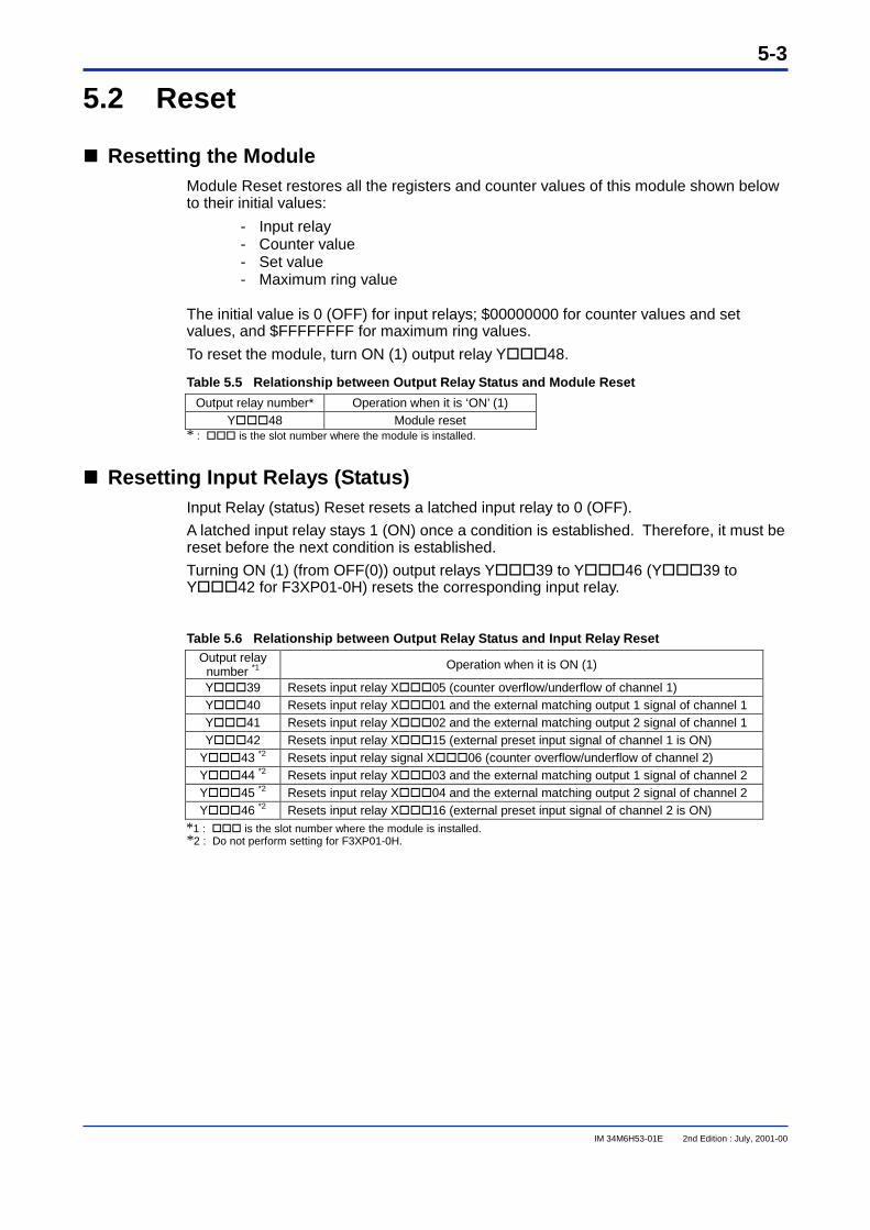
���� Resetting the ModuleModule Reset restores all the registers and counter values of this module shown belowto their initial values:
- Input relay- Counter value- Set value- Maximum ring value
The initial value is 0 (OFF) for input relays; $00000000 for counter values and setvalues, and $FFFFFFFF for maximum ring values.
To reset the module, turn ON (1) output relay Y���48.
Table 5.5 Relationship between Output Relay Status and Module Reset
Output relay number* Operation when it is ‘ON’ (1)Y���48 Module reset
* : ��� is the slot number where the module is installed.
���� Resetting Input Relays (Status)Input Relay (status) Reset resets a latched input relay to 0 (OFF).
A latched input relay stays 1 (ON) once a condition is established. Therefore, it must bereset before the next condition is established.
Turning ON (1) (from OFF(0)) output relays Y���39 to Y���46 (Y���39 toY���42 for F3XP01-0H) resets the corresponding input relay.
Table 5.6 Relationship between Output Relay Status and Input Relay ResetOutput relay
number *1 Operation when it is ON (1)
Y���39 Resets input relay X���05 (counter overflow/underflow of channel 1)Y���40 Resets input relay X���01 and the external matching output 1 signal of channel 1Y���41 Resets input relay X���02 and the external matching output 2 signal of channel 1Y���42 Resets input relay X���15 (external preset input signal of channel 1 is ON)
Y���43 *2 Resets input relay signal X���06 (counter overflow/underflow of channel 2)Y���44 *2 Resets input relay X���03 and the external matching output 1 signal of channel 2Y���45 *2 Resets input relay X���04 and the external matching output 2 signal of channel 2Y���46 *2 Resets input relay X���16 (external preset input signal of channel 2 is ON)
*1 : ��� is the slot number where the module is installed.*2 : Do not perform setting for F3XP01-0H.

Blank Page
6-1
IM 34M6H53-01E 2nd Edition : July, 2001-00
6. Accessing the ModuleThis module can be accessed either using a ladder sequence or a BASIC program.Access is via input/output registers and input/output relays of the module.
6.1 Accessing Using Ladder Application Instructions
���� Reading the Counter Value, Set Value, Maximum Ring Value andPreset Value
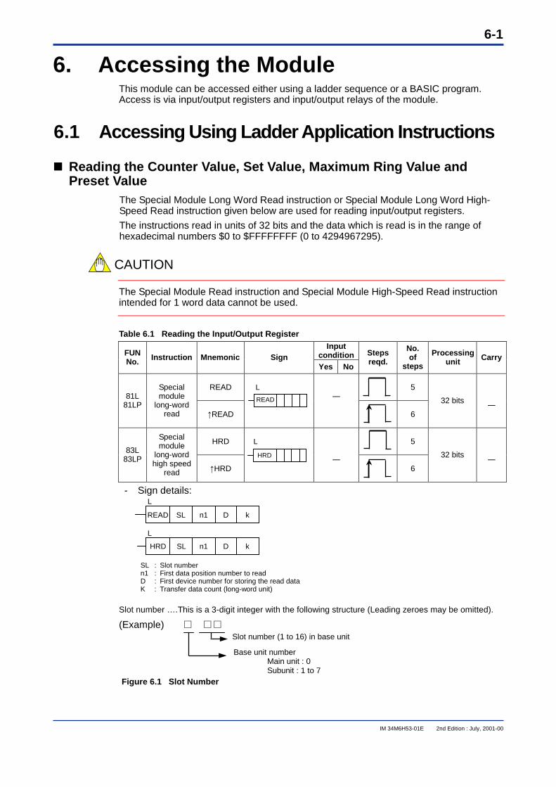
The Special Module Long Word Read instruction or Special Module Long Word High-Speed Read instruction given below are used for reading input/output registers.
The instructions read in units of 32 bits and the data which is read is in the range ofhexadecimal numbers $0 to $FFFFFFFF (0 to 4294967295).
CAUTION
The Special Module Read instruction and Special Module High-Speed Read instructionintended for 1 word data cannot be used.
Table 6.1 Reading the Input/Output RegisterInput
conditionFUNNo. Instruction Mnemonic Sign
Yes No
Stepsreqd.
No.of
steps
Processingunit Carry
READ 581L
81LP
Specialmodule
long-wordread ↑READ
L―
6
32 bits ―
HRD 583L
83LP
Specialmodule
long-wordhigh speed
read ↑HRD
L
―6
32 bits ―
- Sign details:L
L
SL : Slot numbern1 : First data position number to readD : First device number for storing the read dataK : Transfer data count (long-word unit)
Slot number ….This is a 3-digit integer with the following structure (Leading zeroes may be omitted).
(Example) □ □□�
Figure 6.1 Slot Number
READ
HRD
SL n1 D kREAD
Slot number (1 to 16) in base unit
Base unit numberMain unit : 0Subunit : 1 to 7
HRD SL n1 D k
6-2
IM 34M6H53-01E 2nd Edition : July, 2001-00
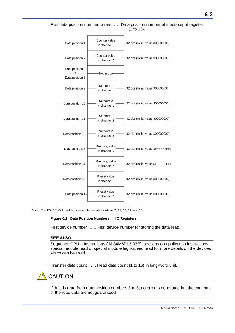
First data position number to read……Data position number of input/output register(1 to 16).
Data position 1
Data position 2
Data position 8
Data position 3
Data position 9
Data position 10
Data position 11
Data position 12
Data position13
Data position 14
Data position 15
Data position 16
Counter value
in channel 1
Counter value
in channel 2
Not in use
Setpoint 1
in channel 1
Setpoint 2
in channel 1
Setpoint 1
in channel 2
Setpoint 2
in channel 2
Max. ring value
in channel 1
Max. ring value
in channel 2
Preset value
in channel 1
Preset value
in channel 2
32 bits (Initial value $00000000)
32 bits (Initial value $00000000)
32 bits (Initial value $00000000)
32 bits (Initial value $00000000)
32 bits (Initial value $00000000)
32 bits (Initial value $00000000)
32 bits (Initial value $FFFFFFFF)
32 bits (Initial value $FFFFFFFF)
32 bits (Initial value $00000000)
32 bits (Initial value $00000000)
Note: The F3XP01-0H module does not have data locations 2, 11, 12, 14, and 16.
to
Figure 6.2 Data Position Numbers in I/O Registers
First device number …… First device number for storing the data read.
SEE ALSOSequence CPU – Instructions (IM 34M6P12-03E), sections on application instructions,special module read or special module high-speed read for more details on the deviceswhich can be used.
Transfer data count …… Read data count (1 to 16) in long-word unit.
CAUTION
If data is read from data position numbers 3 to 8, no error is generated but the contentsof the read data are not guaranteed.
6-3
IM 34M6H53-01E 2nd Edition : July, 2001-00
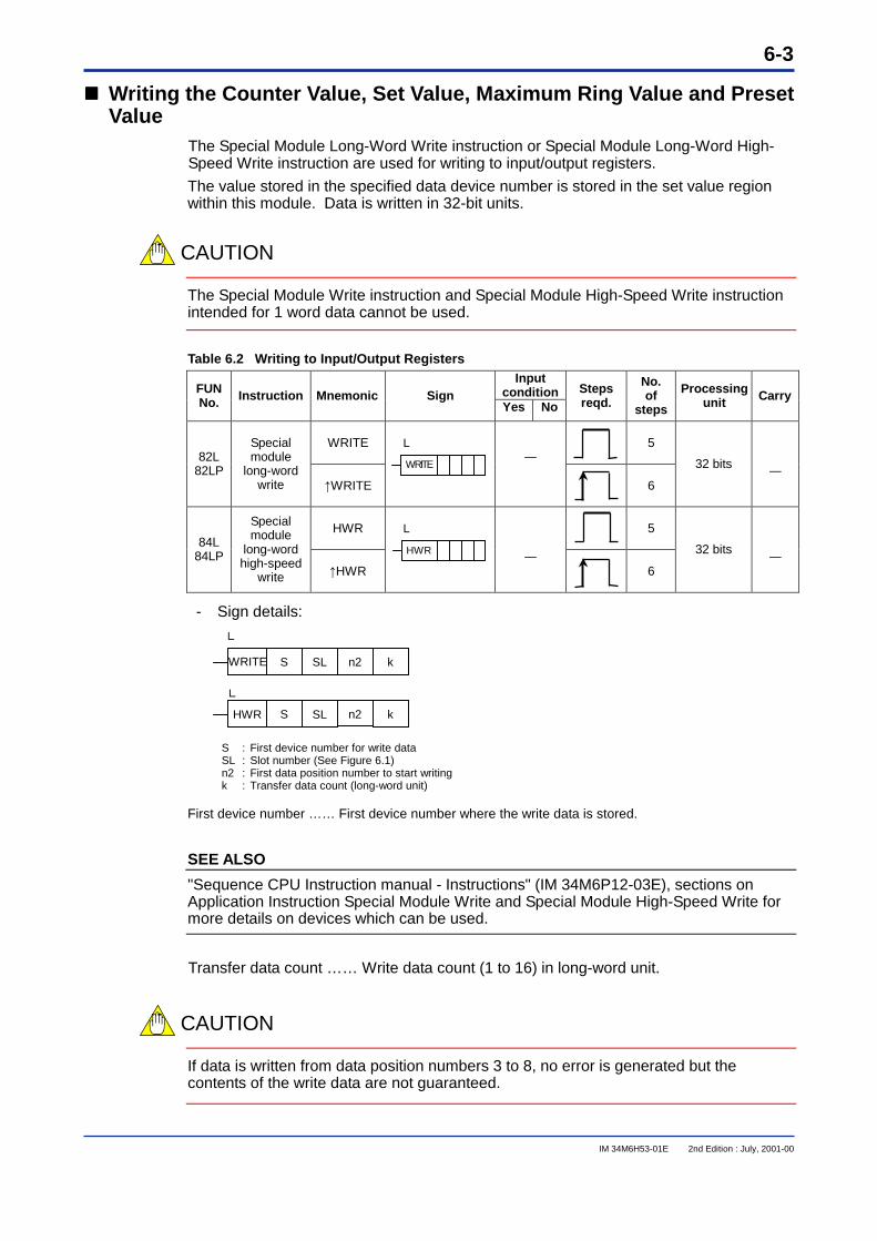
���� Writing the Counter Value, Set Value, Maximum Ring Value and PresetValue
The Special Module Long-Word Write instruction or Special Module Long-Word High-Speed Write instruction are used for writing to input/output registers.
The value stored in the specified data device number is stored in the set value regionwithin this module. Data is written in 32-bit units.
CAUTION
The Special Module Write instruction and Special Module High-Speed Write instructionintended for 1 word data cannot be used.
Table 6.2 Writing to Input/Output RegistersInput
conditionFUNNo. Instruction Mnemonic Sign
Yes NoStepsreqd.
No.of
steps
Processingunit Carry
WRITE 582L
82LP
Specialmodule
long-wordwrite ↑WRITE
L―
6
32 bits ―
HWR 584L
84LP
Specialmodule
long-wordhigh-speed
write ↑HWR
L
―6
32 bits ―
- Sign details:
L
L
S : First device number for write dataSL : Slot number (See Figure 6.1)n2 : First data position number to start writingk : Transfer data count (long-word unit)
First device number …… First device number where the write data is stored.
SEE ALSO
"Sequence CPU Instruction manual - Instructions" (IM 34M6P12-03E), sections onApplication Instruction Special Module Write and Special Module High-Speed Write formore details on devices which can be used.
Transfer data count …… Write data count (1 to 16) in long-word unit.
CAUTION
If data is written from data position numbers 3 to 8, no error is generated but thecontents of the write data are not guaranteed.
S SL n2 kWRITE
S SL n2 kHWR
WRITE
HWR
6-4
IM 34M6H53-01E 2nd Edition : July, 2001-00
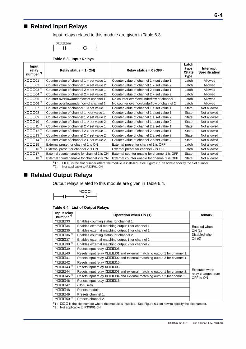
���� Related Input RelaysInput relays related to this module are given in Table 6.3
Table 6.3 Input Relays
Inputrelay
number *1Relay status = 1 (ON) Relay status = 0 (OFF)
Latchtype
/Statetype
InterruptSpecification
X���01 Counter value of channel 1 = set value 1 Counter value of channel 1 ≠ set value 1 Latch AllowedX���02 Counter value of channel 1 = set value 2 Counter value of channel 1 ≠ set value 2 Latch AllowedX���03 *2 Counter value of channel 2 = set value 1 Counter value of channel 2 ≠ set value 1 Latch AllowedX���04 *2 Counter value of channel 2 = set value 2 Counter value of channel 2 ≠ set value 2 Latch AllowedX���05 Counter overflow/underflow of channel 1 No counter overflow/underflow of channel 1 Latch AllowedX���06 *2 Counter overflow/underflow of channel 2 No counter overflow/underflow of channel 2 Latch AllowedX���07 Counter value of channel 1 < set value 1 Counter value of channel 1 ≥ set value 1 State Not allowedX���08 Counter value of channel 1 >set value 1 Counter value of channel 1 ≤ set value 1 State Not allowedX���09 Counter value of channel 1 < set value 2 Counter value of channel 1 ≥ set value 2 State Not allowedX���10 Counter value of channel 1 > set value 2 Counter value of channel 1 ≤ set value 2 State Not allowedX���11 *2 Counter value of channel 2 < set value 1 Counter value of channel 2 ≥ set value 1 State Not allowedX���12 *2 Counter value of channel 2 > set value 1 Counter value of channel 2 ≤ set value 1 State Not allowedX���13 *2 Counter value of channel 2 < set value 2 Counter value of channel 2 ≥ set value 2 State Not allowedX���14 *2 Counter value of channel 2 > set value 2 Counter value of channel 2 ≤ set value 2 State Not allowedX���15 External preset for channel 1 is ON External preset for channel 1 is OFF Latch Not allowedX���16 *2 External preset for channel 2 is ON External preset for channel 2 is OFF Latch Not allowedX���17 External counter enable for channel 1 is ON External counter enable for channel 1 is OFF State Not allowedX���18 *2 External counter enable for channel 2 is ON External counter enable for channel 2 is OFF State Not allowed
*1 : ��� is the slot number where the module is installed. See Figure 6.1 on how to specify the slot number.*2 : Not applicable to F3XP01-0H.
���� Related Output RelaysOutput relays related to this module are given in Table 6.4.
Table 6.4 List of Output RelaysInput relaynumber *1 Operation when ON (1) Remark
Y���33 Enables counting status for channel 1.Y���34 Enables external matching output 1 for channel 1.Y���35 Enables external matching output 2 for channel 1.Y���36 *2 Enables counting status for channel 2.Y���37 *2 Enables external matching output 1 for channel 2.Y���38 *2 Enables external matching output 2 for channel 2.
Enabled whenON (1)Disabled whenOff (0)
Y���39 Resets input relay X���05.Y���40 Resets input relay X���01 and external matching output 1 for channel 1.Y���41 Resets input relay X���02 and external matching output 2 for channel 1.Y���42 Resets input relay X���15.Y���43 *2 Resets input relay X���06.Y���44 *2 Resets input relay X���03 and external matching output 1 for channel 2.Y���45 *2 Resets input relay X���04 and external matching output 2 for channel 2.Y���46 *2 Resets input relay X���16.Y���47 (Not used)Y���48 Resets module.Y���49 Presets channel 1.Y���50 *2 Presets channel 2.
Executes whenrelay changes fromOFF to ON
*1 : ��� is the slot number where the module is installed. See Figure 6.1 on how to specify the slot number.*2 : Not applicable to F3XP01-0H.
X���nn
Y���nn
6-5
IM 34M6H53-01E 2nd Edition : July, 2001-00
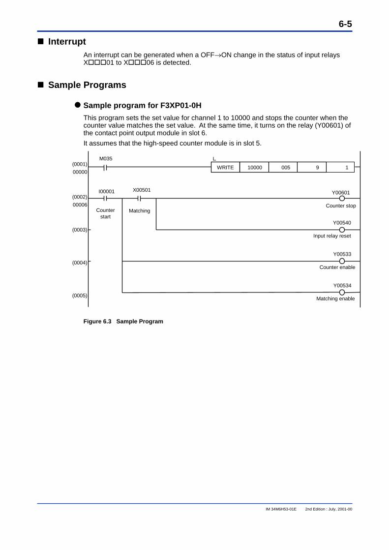
���� InterruptAn interrupt can be generated when a OFF→ON change in the status of input relaysX���01 to X���06 is detected.
���� Sample Programs
���� Sample program for F3XP01-0H
This program sets the set value for channel 1 to 10000 and stops the counter when thecounter value matches the set value. At the same time, it turns on the relay (Y00601) ofthe contact point output module in slot 6.
It assumes that the high-speed counter module is in slot 5.
Figure 6.3 Sample Program
(0001)
00000
(0002)
00006
(0003)
(0004)
(0005)
WRITE 10000 005 9 1
Y00533
Counter enable
Y00534
Matching enable
M035
I00001 X00501
Counterstart
Y00601
Counter stop
Y00540
Input relay reset
Matching
L
6-6
IM 34M6H53-01E 2nd Edition : July, 2001-00
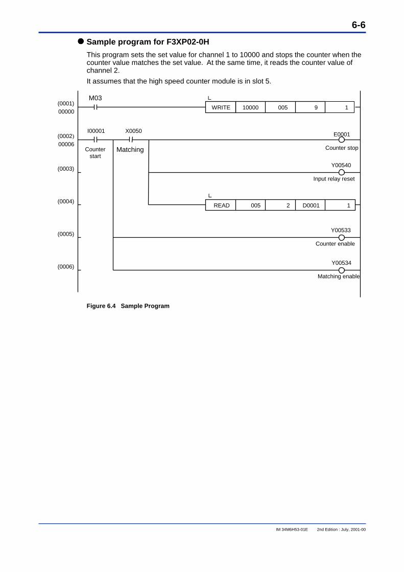
���� Sample program for F3XP02-0H
This program sets the set value for channel 1 to 10000 and stops the counter when thecounter value matches the set value. At the same time, it reads the counter value ofchannel 2.
It assumes that the high speed counter module is in slot 5.
Figure 6.4 Sample Program
WRITE 10000 005 9 1
READ 005 2 D0001 1
Y00533
Counter enable
Y00534
Matching enable
E0001 Counter stop
Y00540
Input relay reset
(0001)00000
(0002)
00006
(0003)
(0004)
(0005)
(0006)
M03
I00001 X0050
Counterstart
Matching
L
L

6-7
IM 34M6H53-01E 2nd Edition : July, 2001-00
6.2 Accessing Using BASIC StatementsBASIC statements shown in Table 6.5 can be used for the module. Operation is notguaranteed when BASIC statements other than those in Table 6.5 are used.
Table 6.5 BASIC Statements that Can Be Used in the ModuleFunction Statement Syntax Explanation
Declare use ofmodule
ASSIGN ID=SLID: Module ID (XP02 or XP01)SL: Slot number
Defines module ID and slot number wherethe module is installed
Read countervalue
ENTER SL, n BFORMAT;LorENTER SL BFORMAT;L(*)
SL: Slot numbern: Data position number (1 or 2)L: Long integer variable name or long integer array
Variable name (long word) for storing the readdata
L(*): Long integer array variable name for storing readdata. (In case of batch specification)
Reads the counter value (in the range of 0 to$FFFFFFF) of data position n of High-speedCounter module installed in slot number SLand stores it in variable L.If the data position number is not specified, itstores the counter value read sequentiallystarting from data position number 1 in arrayvariable L (*).
Read set value,maximum ringvalue, presetvalue
LSTATUS(SL,n,L)SL: Slot numbern: Data position number (1 to 15)L: Read data storage variable (long word)
It reads the set value, maximum ring value orpreset value of data position number n of themodule installed in slot number SL andstores them in variable L.
Write set value,maximum ringvalue, presetvalue
LCONTROL(SL,n,L)SL: Slot numbern: Data position number (1 to 15)L: Read data storage variable (long word)
Stores numeric value or contents of thenumeric variable specified by L in dataposition number n of the module installed inslot number SL.
Read input relay LSTATUS (SL,101,L)SL: Slot numberL: Storage variable for read value (long word)
Reads the status of input relays X���01 toX���18 of the module installed in slotnumber SL and stores it in variable L.
Write to outputrelay (output)
CONTROL SL,N;I,MSL: Slot numberN: Register number (101 or 102)I: Output data
Numeric value integer variableName or integer array variableName (word
M: Mask pattern (word)
Outputs to output relays Y���33 toY���50 of the module installed in slotnumber SL. If a mask pattern is used, onlyspecific output relays can be accessed.
Interruptdetection
ON INT SL, n GOTOON INT SL, n GOSUBON INT SL, n CALL
SL: Slot numbern: Input relay number (1 to 6)
Detects OFF→ON change of input relays.X���01 to X���06 of the moduleinstalled in slot number SL and generates aninterrupt.
(Note) LCONTROL and LSTATUS statements are high-speed libraries which can be used in this module.
���� Declaring Use of ModuleThis declares use of this module. Always execute this statement before using theENTER, LCONTROL, LSTATUS statements in this module, and define the slot numberin which the module is installed.
Module ID……Specify using the character string shown below, depending on the module to be used.
Model Module ID (character string)F3XP01-0H XP01F3XP02-0H XP02
Slot number…… 3-digit integer with the following structure (Leading zeroes may be omitted).
(Example) □ □□
ASSIGN ID= SL
Module slot number
Module ID
Base unit number Main unit : 0
Subunit : 1 to 7
Slot numbers (1 to 16) in base unit
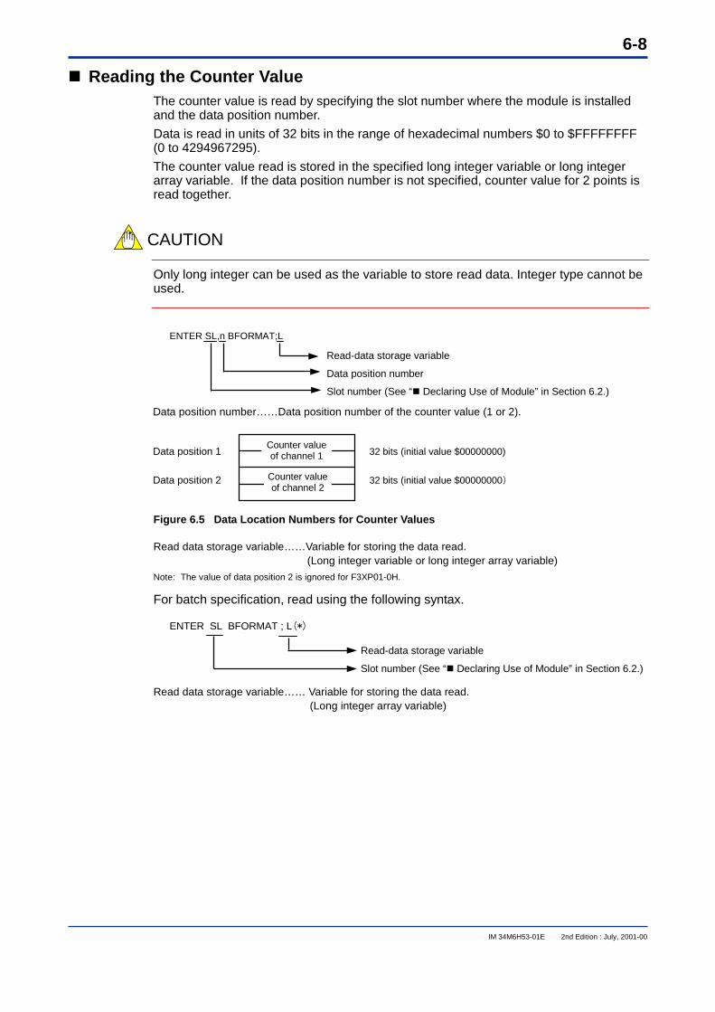
6-8
IM 34M6H53-01E 2nd Edition : July, 2001-00
���� Reading the Counter ValueThe counter value is read by specifying the slot number where the module is installedand the data position number.
Data is read in units of 32 bits in the range of hexadecimal numbers $0 to $FFFFFFFF(0 to 4294967295).
The counter value read is stored in the specified long integer variable or long integerarray variable. If the data position number is not specified, counter value for 2 points isread together.
CAUTION
Only long integer can be used as the variable to store read data. Integer type cannot beused.
Data position number……Data position number of the counter value (1 or 2).
Figure 6.5 Data Location Numbers for Counter Values
Read data storage variable……Variable for storing the data read.(Long integer variable or long integer array variable)
Note: The value of data position 2 is ignored for F3XP01-0H.
For batch specification, read using the following syntax.
Read data storage variable…… Variable for storing the data read.(Long integer array variable)
ENTER SL,n BFORMAT;L
Read-data storage variable
Data position number
Slot number (See “� Declaring Use of Module” in Section 6.2.)
Data position 1 32 bits (initial value $00000000)
Data position 2 32 bits (initial value $00000000)
Counter valueof channel 1
Counter valueof channel 2
ENTER SL BFORMAT ; L(*)
Read-data storage variable
Slot number (See “� Declaring Use of Module” in Section 6.2.)
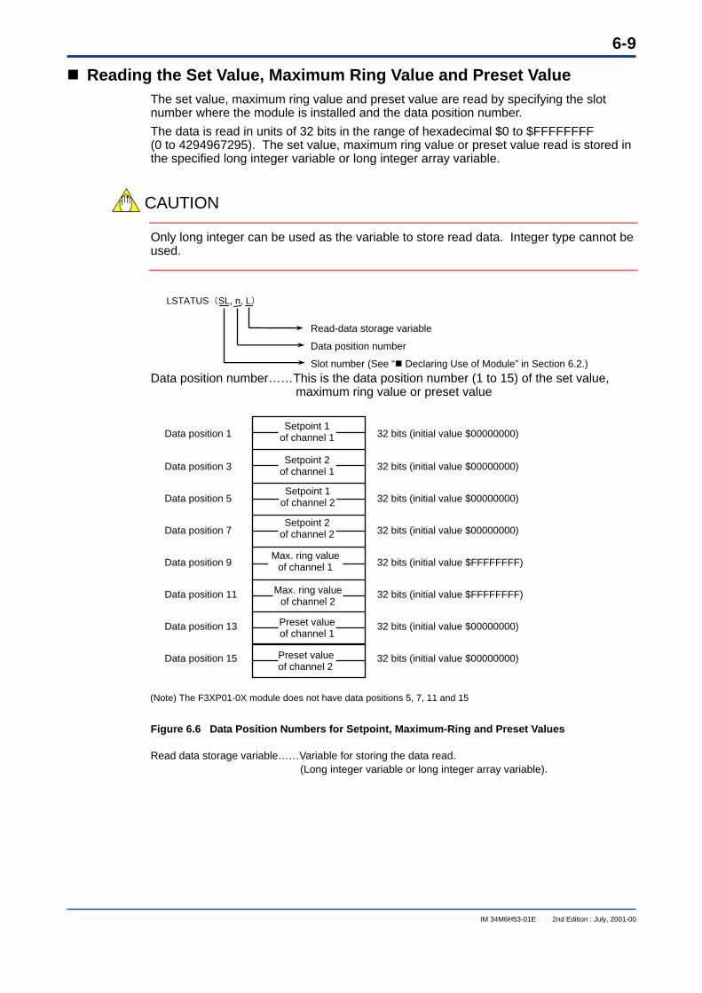
6-9
IM 34M6H53-01E 2nd Edition : July, 2001-00
Reading the Set Value, Maximum Ring Value and Preset Value The set value, maximum ring value and preset value are read by specifying the slot number where the module is installed and the data position number. The data is read in units of 32 bits in the range of hexadecimal $0 to $FFFFFFFF (0 to 4294967295). The set value, maximum ring value or preset value read is stored in the specified long integer variable or long integer array variable.
CAUTION
Only long integer can be used as the variable to store read data. Integer type cannot be used.
Data position number……This is the data position number (1 to 15) of the set value,
maximum ring value or preset value
(Note) The F3XP01-0X module does not have data positions 5, 7, 11 and 15 Figure 6.6 Data Position Numbers for Setpoint, Maximum-Ring and Preset Values
Read data storage variable……Variable for storing the data read. (Long integer variable or long integer array variable).
Data position 1 32 bits (initial value $00000000)
Data position 3 32 bits (initial value $00000000)
Data position 5 32 bits (initial value $00000000)
Data position 7 32 bits (initial value $00000000)
Data position 9 32 bits (initial value $FFFFFFFF)
Data position 11 32 bits (initial value $FFFFFFFF)
Data position 13 32 bits (initial value $00000000)
Data position 15 32 bits (initial value $00000000)
LSTATUS(SL, n, L)
Read-data storage variable
Data position number
Slot number (See “ Declaring Use of Module” in Section 6.2.)
Setpoint 1 of channel 1
Setpoint 2 of channel 1
Setpoint 1 of channel 2
Max. ring valueof channel 1
Max. ring valueof channel 2
Preset value of channel 1
Preset value of channel 2
Setpoint 2 of channel 2
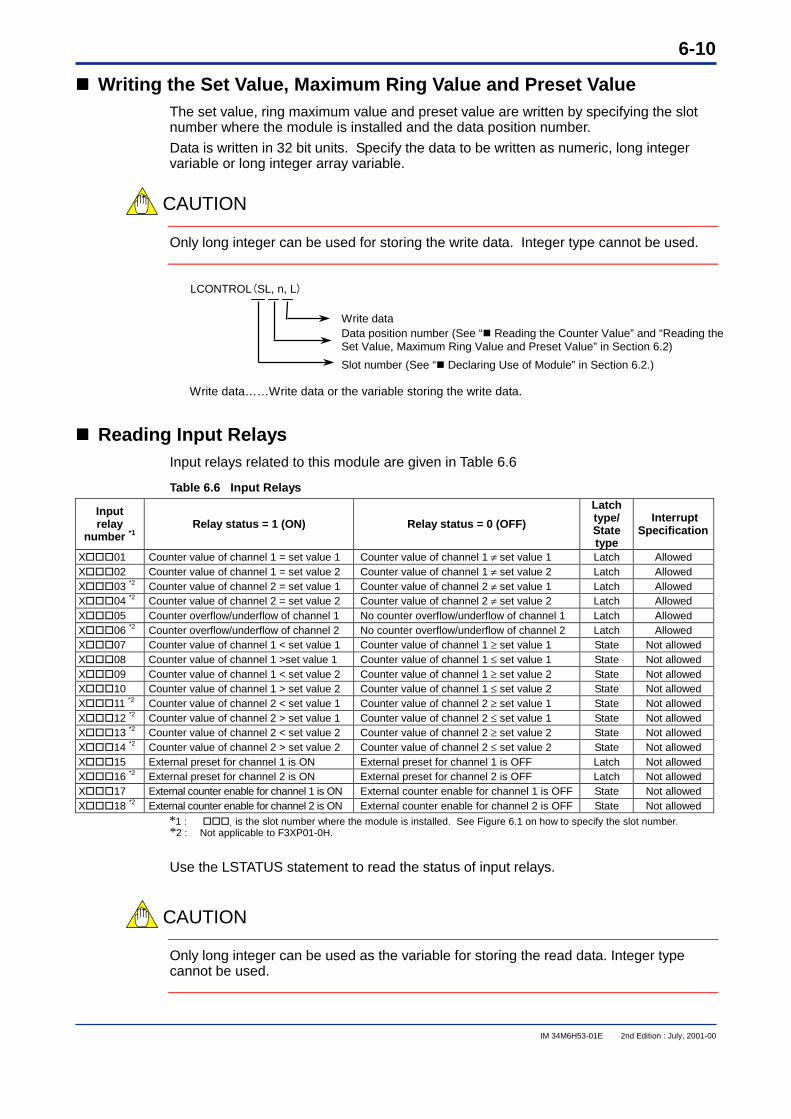
6-10
IM 34M6H53-01E 2nd Edition : July, 2001-00
���� Writing the Set Value, Maximum Ring Value and Preset ValueThe set value, ring maximum value and preset value are written by specifying the slotnumber where the module is installed and the data position number.
Data is written in 32 bit units. Specify the data to be written as numeric, long integervariable or long integer array variable.
CAUTION
Only long integer can be used for storing the write data. Integer type cannot be used.
Write data……Write data or the variable storing the write data.
���� Reading Input RelaysInput relays related to this module are given in Table 6.6
Table 6.6 Input Relays
Inputrelay
number *1Relay status = 1 (ON) Relay status = 0 (OFF)
Latchtype/Statetype
InterruptSpecification
X���01 Counter value of channel 1 = set value 1 Counter value of channel 1 ≠ set value 1 Latch AllowedX���02 Counter value of channel 1 = set value 2 Counter value of channel 1 ≠ set value 2 Latch AllowedX���03 *2 Counter value of channel 2 = set value 1 Counter value of channel 2 ≠ set value 1 Latch AllowedX���04 *2 Counter value of channel 2 = set value 2 Counter value of channel 2 ≠ set value 2 Latch AllowedX���05 Counter overflow/underflow of channel 1 No counter overflow/underflow of channel 1 Latch AllowedX���06 *2 Counter overflow/underflow of channel 2 No counter overflow/underflow of channel 2 Latch AllowedX���07 Counter value of channel 1 < set value 1 Counter value of channel 1 ≥ set value 1 State Not allowedX���08 Counter value of channel 1 >set value 1 Counter value of channel 1 ≤ set value 1 State Not allowedX���09 Counter value of channel 1 < set value 2 Counter value of channel 1 ≥ set value 2 State Not allowedX���10 Counter value of channel 1 > set value 2 Counter value of channel 1 ≤ set value 2 State Not allowedX���11 *2 Counter value of channel 2 < set value 1 Counter value of channel 2 ≥ set value 1 State Not allowedX���12 *2 Counter value of channel 2 > set value 1 Counter value of channel 2 ≤ set value 1 State Not allowedX���13 *2 Counter value of channel 2 < set value 2 Counter value of channel 2 ≥ set value 2 State Not allowedX���14 *2 Counter value of channel 2 > set value 2 Counter value of channel 2 ≤ set value 2 State Not allowedX���15 External preset for channel 1 is ON External preset for channel 1 is OFF Latch Not allowedX���16 *2 External preset for channel 2 is ON External preset for channel 2 is OFF Latch Not allowedX���17 External counter enable for channel 1 is ON External counter enable for channel 1 is OFF State Not allowedX���18 *2 External counter enable for channel 2 is ON External counter enable for channel 2 is OFF State Not allowed
*1 : ��� is the slot number where the module is installed. See Figure 6.1 on how to specify the slot number.*2 : Not applicable to F3XP01-0H.
Use the LSTATUS statement to read the status of input relays.
CAUTION
Only long integer can be used as the variable for storing the read data. Integer typecannot be used.
LCONTROL(SL, n, L)
Write dataData position number (See “� Reading the Counter Value” and “Reading theSet Value, Maximum Ring Value and Preset Value” in Section 6.2)
Slot number (See “� Declaring Use of Module” in Section 6.2.)
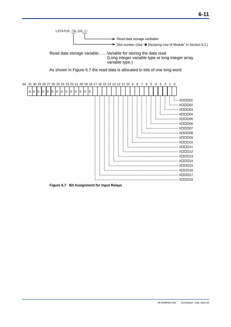
6-11
IM 34M6H53-01E 2nd Edition : July, 2001-00
Read data storage variable……Variable for storing the data read(Long integer variable type or long integer arrayvariable type.)
As shown in Figure 6.7 the read data is allocated to bits of one long word.
Figure 6.7 Bit Assignment for Input Relays
Read-data storage varibable
Slot number (See “� Declaring Use of Module” in Section 6.2.)
31 30 29 28 27 26 25 24 23 22 21 20 19 18 17 16 15 14 13 12 11 10 9 8 7 6 5 4 3 2 1 0
0 0 0 0 0 0 0 0 0 0 0 0 0 0
X���01
X���02
X���03
X���04
X���05
X���06
X���07
X���08
X���09
X���10
X���11
X���12
X���13
X���14
X���15
X���16
X���17
X���18
bit
LSTATUS(SL,101, L)
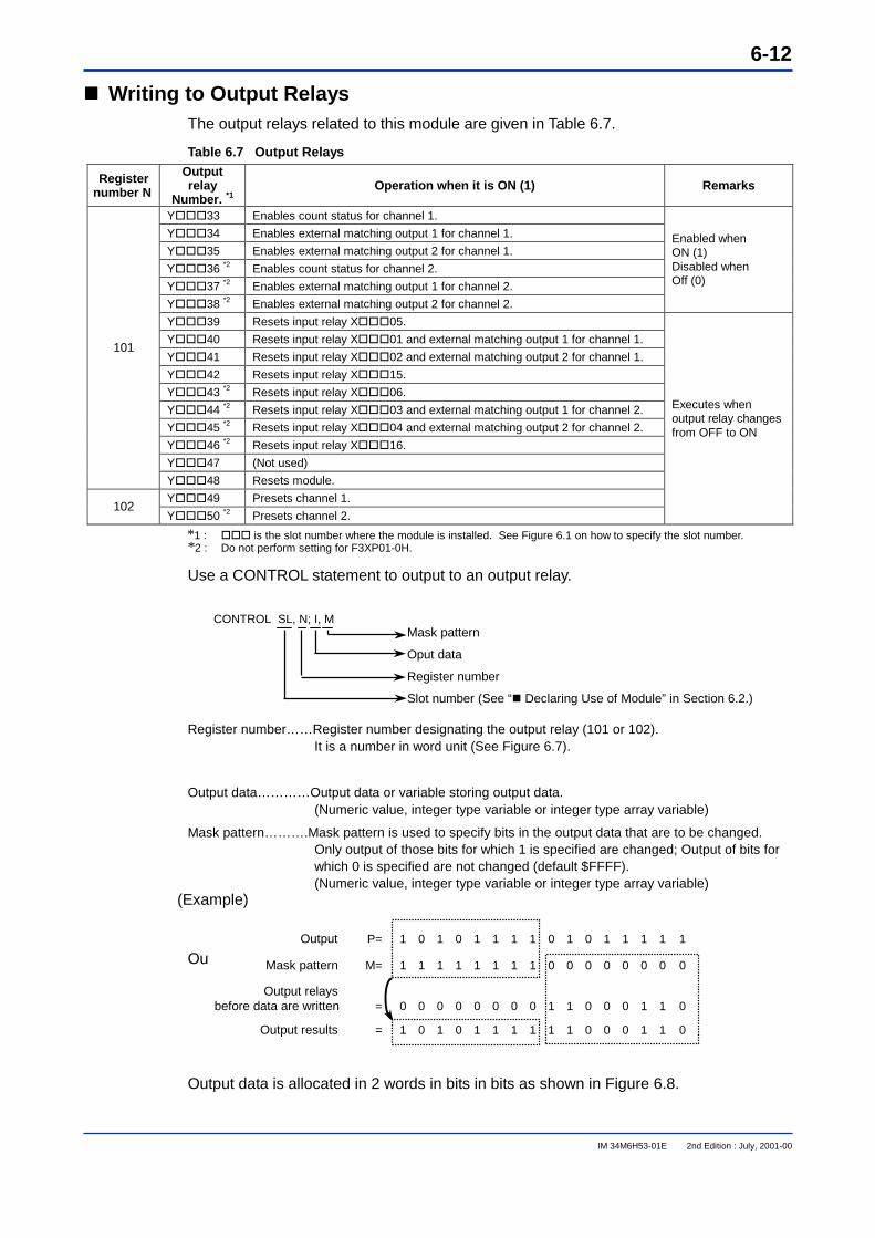
6-12
IM 34M6H53-01E 2nd Edition : July, 2001-00
���� Writing to Output RelaysThe output relays related to this module are given in Table 6.7.
Table 6.7 Output Relays
Registernumber N
Outputrelay
Number. *1Operation when it is ON (1) Remarks
Y���33 Enables count status for channel 1.
Y���34 Enables external matching output 1 for channel 1.
Y���35 Enables external matching output 2 for channel 1.
Y���36 *2 Enables count status for channel 2.
Y���37 *2 Enables external matching output 1 for channel 2.
Y���38 *2 Enables external matching output 2 for channel 2.
Enabled whenON (1)Disabled whenOff (0)
Y���39 Resets input relay X���05.
Y���40 Resets input relay X���01 and external matching output 1 for channel 1.
Y���41 Resets input relay X���02 and external matching output 2 for channel 1.
Y���42 Resets input relay X���15.
Y���43 *2 Resets input relay X���06.
Y���44 *2 Resets input relay X���03 and external matching output 1 for channel 2.
Y���45 *2 Resets input relay X���04 and external matching output 2 for channel 2.
Y���46 *2 Resets input relay X���16.
Y���47 (Not used)
101
Y���48 Resets module.
Y���49 Presets channel 1.102
Y���50 *2 Presets channel 2.
Executes whenoutput relay changesfrom OFF to ON
*1 : ��� is the slot number where the module is installed. See Figure 6.1 on how to specify the slot number.*2 : Do not perform setting for F3XP01-0H.
Use a CONTROL statement to output to an output relay.
Register number……Register number designating the output relay (101 or 102).It is a number in word unit (See Figure 6.7).
Output data…………Output data or variable storing output data.(Numeric value, integer type variable or integer type array variable)
Mask pattern……….Mask pattern is used to specify bits in the output data that are to be changed.Only output of those bits for which 1 is specified are changed; Output of bits forwhich 0 is specified are not changed (default $FFFF).(Numeric value, integer type variable or integer type array variable)
(Example)
Output data is allocated as bits in 2 words as shown in Figure 6.8.
Output data is allocated in 2 words in bits in bits as shown in Figure 6.8.
CONTROL SL, N; I, MMask pattern
Oput data
Register number
Slot number (See “� Declaring Use of Module” in Section 6.2.)
Output P= 1 0 1 0 1 1 1 1 0 1 0 1 1 1 1 1
Mask pattern M= 1 1 1 1 1 1 1 1 0 0 0 0 0 0 0 0
Output relaysbefore data are written = 0 0 0 0 0 0 0 0 1 1 0 0 0 1 1 0
Output results = 1 0 1 0 1 1 1 1 1 1 0 0 0 1 1 0
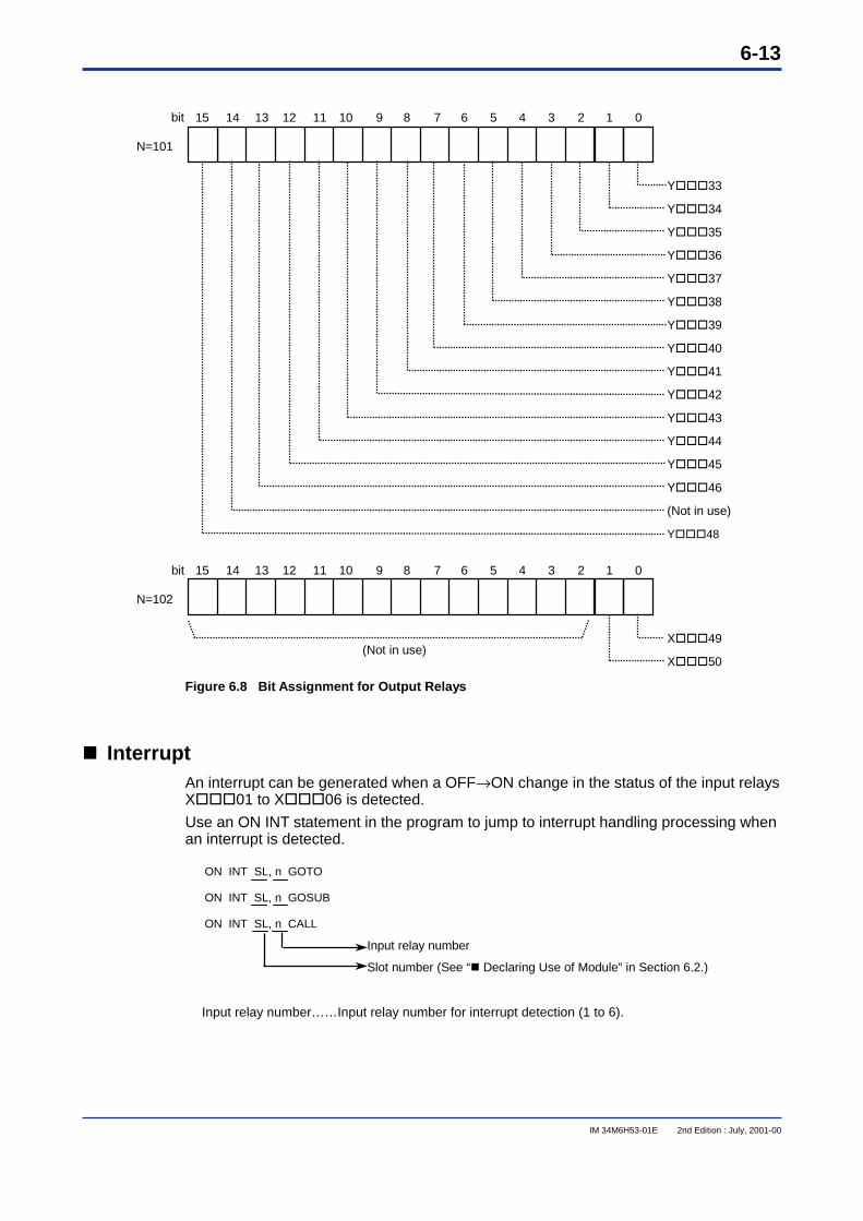
6-13
IM 34M6H53-01E 2nd Edition : July, 2001-00
Figure 6.8 Bit Assignment for Output Relays
���� InterruptAn interrupt can be generated when a OFF→ON change in the status of the input relaysX���01 to X���06 is detected.
Use an ON INT statement in the program to jump to interrupt handling processing whenan interrupt is detected.
Input relay number……Input relay number for interrupt detection (1 to 6).
15 14 13 12 11 10 9 8 7 6 5 4 3 2 1 0
Y���33
Y���34
Y���35
Y���36
Y���37
Y���38
Y���39
Y���40
Y���41
Y���42
Y���43
Y���44
Y���45
Y���46
(Not in use)
Y���48
bit
15 14 13 12 11 10 9 8 7 6 5 4 3 2 1 0bit
X���49
X���50 (Not in use)
N=101
N=102
ON INT SL, n GOTO
ON INT SL, n GOSUB
ON INT SL, n CALL
Input relay number
Slot number (See “� Declaring Use of Module” in Section 6.2.)
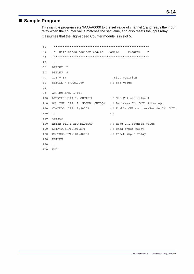
6-14
IM 34M6H53-01E 2nd Edition : July, 2001-00
���� Sample ProgramThis sample program sets $AAAA0000 to the set value of channel 1 and reads the inputrelay when the counter value matches the set value, and also resets the input relay.
It assumes that the High-speed Counter module is in slot 5.
10 !******************************************************
20 !* High speed counter module Sample Program *
30 !******************************************************
40 !
50 DEFINT I
60 DEFLNG S
70 ITI = 5: !Slot position
80 SETTEL = $AAAA0000 : ! Set value
80 !
90 ASSIGN XPO2 = ITI
100 LCONTROL(ITI,1, SETTEI) : ! Set CH1 set value 1
110 ON INT ITI, 1 GOSUB CNTEQ@ : ! Declares CH1 OUT1 interrupt
120 CONTROL ITI, 1;$0003 : ! Enable CH1 counter/Enable CH1 OUT1
130 ! : !
140 CNTEQ@
150 ENTER ITI,1 BFORMAT;SCT : ! Read CH1 counter value
160 LSTATUS(ITI,101,ST) : ! Read input relay
170 CONTROL ITI,101;$0080 : ! Reset input relay
180 RETURN
190 !
200 END
i
IM 34M6H53-01E 2nd Edition : July, 2001-00
Revision InformationDocument Name : High-speed Counter Modules
Document No. : IM 34M6H53-01E
Edition Date Revised Item1st Feb, 1999 New Publication2nd July, 2001 Addition of explanations on support of CE Mark; Correction of typographical errors
Written by Product Marketing Department, IT Controller Center.Yokogawa Electric Corporation
Published by Yokogawa Electric Corporation2-9-32 Nakacho, Musashino-shi, Tokyo, 180-8750, JAPAN
Printed by Yokogawa Graphic Arts Co., Ltd.

Blank Page
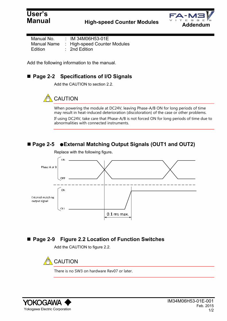
IM34M06H53-01E-001 Feb. 2015
1/2
Yokogawa Electric Corporation
Manual No. : IM 34M06H53-01E Manual Name : High-speed Counter Modules Edition : 2nd Edition
Add the following information to the manual.
Page 2-2 Specifications of I/O Signals Add the CAUTION to section 2.2.
CAUTION
When powering the module at DC24V, leaving Phase-A/B ON for long periods of time may result in heat-induced deterioration (discoloration) of the case or other problems. If using DC24V, take care that Phase-A/B is not forced ON for long periods of time due to abnormalities with connected instruments.
Page 2-5 ●External Matching Output Signals (OUT1 and OUT2) Replace with the following figure.
Page 2-9 Figure 2.2 Location of Function Switches Add the CAUTION to figure 2.2.
CAUTION
There is no SW3 on hardware Rev07 or later.
User’s Manual High-speed Counter Modules
Addendum
IM34M06H53-01E-001 2/2
Page 6-3 Writing the Counter Value, Set Value, Maximum Ring Value and Preset Value
The CAUTION changed as follows.
old:
CAUTION
If data is written from data position numbers 3 to 8, no error is generated but the contents of the write data are not guaranteed.
new:
CAUTION
Do not write data to data position numbers 3 to 8. The module might not work properly if any data is written there.