high-performance home technologies: solar thermal
TRANSCRIPT

Prepared by
Pacific Northwest National Laboratory & Oak Ridge National Laboratory
June 4, 2007
June 2007 • NREL/TP-550-41085 PNNL-16362
High-Performance Home Technologies:
Solar Thermal & Photovoltaic Systems
Building America Best Practices SeriesVolume 6

High-Performance Home Technologies:
Solar Thermal & Photovoltaic Systems
Building America Best Practices Series
Prepared by
Pacific Northwest National Laboratory
Michael C. Baechler
Theresa Gilbride, Kathi Ruiz, Heidi Steward
and
Oak Ridge National Laboratory
Pat M. Love
June 4, 2007
DISCLAIMER
This report was prepared as an account of work sponsored by an agency of the United States Government. Neither the United States Government nor any agency thereof, nor Battelle Memorial Institute, nor any of their employees, makes any warranty, express or implied, or assumes any legal liability or responsibility for the accuracy, completeness, or usefulness of any information, apparatus, product, or process disclosed, or represents that its use would not infringe privately owned rights. Reference herein to any specific commercial product, process, or service by trade name, trademark, manufacturer, or otherwise does not necessarily constitute or imply its endorsement, recommendation, or favoring by the United States Government or any agency thereof, or Battelle Memorial Institute. The views and opinions of authors expressed herein do not necessarily state or reflect those of the United States Government or any agency thereof.
June 2007 • NREL/TP-550-41085 PNNL-16362

Building America Best Practices Series for High-Performance Technologies: Solar Thermal & Photovoltaic Systems - JUNE 2007
High-Performance Home Technologies: Solar Thermal & Photovoltaic Systems
Acknowledgments
Building America Best Practices Series
The U.S. Department of Energy’s (DOE) Building America Program is comprised of public/private partnerships that conduct systems research to improve overall housing performance, increase housing durability and comfort, reduce energy use, and increase energy security for America’s homeowners. Program activities focus on finding solutions for both new and existing homes, as well as integrating clean onsite energy systems that will allow homebuilders to provide homes that produce as much energy than they use. In addition to the DOE management and staff, Building America includes seven consortia, four national laboratories, and hundreds of builders, manufacturers, and service providers. Building America works closely with the U.S. Department of Housing and Urban Development’s (HUD) Partnership for Advancing Technology in Housing (PATH) and works with other federal agencies to coordinate research find-ings and disseminate information. In addition, DOE co-manages the ENERGY STAR Program along with the U.S. Environmental Protection Agency. These partners make the Program a successful source of knowledge and innovation for industry practitioners and government policy makers.
The U.S. DOE Building America Program funded the development of this series of handbooks. DOE also funded the Building America consortia and national laboratories to form the basis for these best practices. The seven consortia are listed on the back cover of this document. The consortia have taken on the hard work of applied research, field testing, training builders, and transforming the results into building practices. Numerous drawings, descriptions, photos, and case studies originated with the consortia.
Many builders have chosen to use the Building America process in collaboration with the consortia. Builders are quoted throughout the Best Practices
Series, and more than a dozen builder case studies are featured in this document. These builders deserve thankful recognition for contributing to Building America’s success, the Best Practices Series, and for furthering the application of solar technology.
Building America partners worked diligently on this project to further the cause of energy efficiency, solar energy, and zero energy homes. These groups have voluntarily supplied technical materials, review comments, and photographs. Contributors include the Solar Rating and Certification Corporation, the Florida Solar Energy Center, SunPower Corporation, Heliodyne, Inc., Aztec Solar, Aurora Energy LLC., Decker Homes, Alternative Power Enterprises, Inc., Solargenix Energy LLC, the Sacramento Municipal Utility District, Lakeland Electric, the Southwest Technology Development Institute at New Mexico State University, Rheem Water Heaters, and Solmetric Corporation.
This project required coordination among the national laboratories. Pacific Northwest National Laboratory and Oak Ridge National Laboratory have taken the lead at producing this document. The National Renewable Energy Laboratory made its library of Building America, solar, and zero energy home documents available to the authors, reviewed the drafts, and has responsibility for posting the document to the Building America website. Researchers at Sandia National Laboratory reviewed the document as well.
The authors and DOE offer their gratitude to the many contributors that made this project a success.
Unless otherwise noted, photographs were taken by Michael Baechler of Pacific Northwest National Laboratory.
Building America welcomes reader feedback on the Best Practices Series. Please submit your comments to Michael Baechler ([email protected]) or Pat Love ([email protected]).

High-Performance Home Technologies: Solar Thermal & Photovoltaic Systems
Table of Contents
Building America Best Practices Series
Chapter 1.
Managers’ Overview
Chapter 2.
Solar Sells: Closing the Deal
Chapter 3.
Solar-Thermal Water Heating
Chapter 4.
Photovoltaic Power Generation
Chapter 5.
Planning and Orientation
Chapter 6.
Rack-Mounted Systems
Chapter 7.
Worker Safety
Chapter 8.
Solar Ready
Chapter 9.
Looking Back, Looking Ahead
Appendix I (following the Case Studies)
PV System Installation Checklist Courtesy of ConSol
Case Studies• Bob Ward Companies –
Maximum Efficiency Greenland BelAir, MD
• Centex Avignon Pleasanton, CA
• Clarum Homes’s Vista Montana Watsonville, CA
• CARB Cold Climate Homes Hadley, MA and Madison, WI
• Georgia Department of Natural Resources SIPS Cottage Okefenokee, GA
• Grupe – Carsten Crossings Rocklin, CA
• Habitat for Humanity – Metro Denver Wheat Ridge, CO
• Habitat for Humanity – Loudon County Lenoir City, TN
• John Wesley Miller Companies – Armory Park del Sol Tuscon, AZ
• Premier Homes – Premier Gardens Sacramento, CA
• Pulte Homes – Civano Tucson, AZ
• The Garst House Olympia, WA
• Tindall Homes – Legends at Mansfield Columbus, NJ
Building America Best Practices Series for High-Performance Technologies: Solar Thermal & Photovoltaic Systems - JUNE 2007 p. 1
High-Performance Home Technologies: Solar Thermal & Photovoltaic Systems
Introduction – Reach for the Sky
Building America Best Practices Series
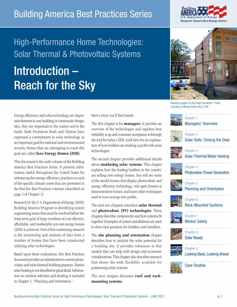
Showing support at the Solar Decathlon. Photo courtesy of Wendy Butler-Burt, DOE.
Chapter 1.
Managers’ Overview
Chapter 2.
Solar Sells: Closing the Deal
Chapter 3.
Solar-Thermal Water Heating
Chapter 4.
Photovoltaic Power Generation
Chapter 5.
Planning and Orientation
Chapter 6.
Rack-Mounted Systems
Chapter 7.
Worker Safety
Chapter 8.
Solar Ready
Chapter 9.
Looking Back, Looking Ahead
Case Studies
Energy efficiency and solar technology are impor-tant elements to any building or community design. Also, they are important to the nation and to the Earth. Both Presidents Bush and Clinton have expressed a commitment to solar technology as an important goal for national and environmental security. Homes that are attempting to reach this goal are called Zero Energy Homes (ZEH).
This document is the sixth volume of the Building America Best Practices Series. It presents infor-mation useful throughout the United States for enhancing the energy-efficiency practices in each of the specific climate zones that are presented in the first five Best Practices volumes (described on page 2 of Chapter 1).
Research by the U.S. Department of Energy (DOE) Building America Program is identifying system engineering issues that must be resolved before the long-term goal of large numbers of cost effective, affordable, and marketable zero net energy homes (ZEH) is achieved. Part of this continuing research is the monitoring and analysis of data from a number of homes that have been constructed utilizing solar technologies.
Based upon these evaluations, this Best Practices document provides an introduction to current photo-voltaic and solar thermal building practices. Passive solar heating is not described in great detail. Informa-tion on window selection and shading is included in Chapter 5, “Planning and Orientation.”
Here’s what you’ll find inside:
The first chapter is for managers. It provides an overview of the technologies and explains how reliability is up and consumer acceptance is through the roof for today’s ZEH. Look here for an explana-tion of how builders are making a profit with solar technologies.
The second chapter provides additional details about marketing solar systems. This chapter explains how the leading builders in the country are selling zero energy homes. You will see some of the model homes that display photovoltaic and energy efficiency technology, visit open houses at demonstration homes, and learn other techniques used to turn savings into profits.
The next two chapters introduce solar thermal and photovoltaic (PV) technologies. These chapters describe components and how systems fit together. Examples of system installations are used to show best practices for builders and installers.
The site planning and orientation chapter describes how to analyze the solar potential for a building site. It provides references to free models that can help with design and economic considerations. This chapter also describes research that shows the wide flexibility available for positioning solar systems.
The next chapter discusses roof and rack-mounting systems.
p. 2 Building America Best Practices Series for High-Performance Technologies: Solar Thermal & Photovoltaic Systems - JUNE 2007
Reach for the Sky INTRODUCTION
Chapter 7 describes safety measures and regula-tions for installers.
Chapter 8 briefly describes how to build homes ready for solar technologies. These solar-ready homes are pre-plumbed, pre-wired, and structurally supported to easily add solar technologies after the initial sale.
The next chapter looks at the history of solar development and some of the great designs from the Solar Decathlon, and summarizes the thirteen case studies described in the next paragraph.
Thirteen case studies are provided at the end of this document. These case studies review building projects of all scales from around the country. The lessons learned apply to building design, materials selection, mounting techniques, and marketing opportunities.
“We can imagine a day when
technologies like solar panels and high-
efficiency appliances…will allow us to
build Zero Energy Homes that produce as
much energy as they consume. That’s the
promise that technology holds for us all.” President George W. Bush, April 27, 2005
“We will work with businesses and
communities to use the sun’s energy
to reduce our reliance on fossil fuels by
installing solar panels on 1 million more
roofs around our nation by 2010.” President Bill Clinton, June 26, 1997.
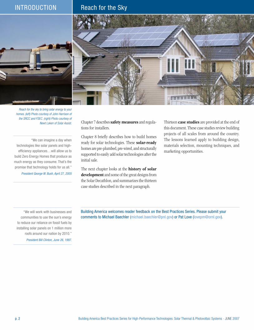
Reach for the sky to bring solar energy to your homes. (left) Photo courtesy of John Harrison of
the SRCC and FSEC. (right) Photo courtesy of Newt Loken of Solar Assist.
Building America welcomes reader feedback on the Best Practices Series. Please submit your comments to Michael Baechler ([email protected]) or Pat Love ([email protected]).

Building America Best Practices Series for High-Performance Technologies: Solar Thermal & Photovoltaic Systems -JUNE 2007 CHAPTER 1 / p.1
High-Performance Home Technologies: Solar Thermal & Photovoltaic Systems
Chapter 1. Managers’ Overview
Building America Best Practices Series
The long-term goal of DOE’s involve-
ment, according to Lew Pratsch, DOE
Zero Energy Homes project manager,
is to make zero energy homes truly
affordable for the average consumer.
Pratsch predicts that within the next
decade, zero energy homes will
be commonplace.
“We set out to provide exceptional value for our customers by adding solar power, and in the process we did something exceptional for our business.”
John Suppes, President of Clarum Homes of Palo Alto, California
Many business owners come to a point in their careers when it is time to bring new energy to their enterprises by inviting in a new generation of partners. This document is literally about bringing new energy into home construction businesses by inviting in a new generation of energy efficiency and solar power.
Building America, DOE’s program for energy efficiency in new home construction, has worked with builders all over the United States for more than ten years to develop comfortable, durable, and efficient houses. Teams of builders and building scientists have proven that energy efficiency is a vital part of quality and value-based construction when incorporated into an integrated systems design. This approach to efficient construction is an essential step in creating consumer value.
(above) It is difficult to pick out houses with integrated photovoltaic systems. All of these homes are so equipped.
Builders’ Brief
• Systems engineered building design and energy efficiency are the best bet for value, comfort, and reliability.
• Highly efficient houses, combined with solar technologies, add up to today’s Zero Energy Homes (ZEH)
– homes with utility bills reduced by at least 50%. Tomorrow’s ZEH will produce as much annual energy as
they consume.
• Innovation has made solar technologies more stylish, reliable, and consumer-friendly.
• Government and utilities at all levels support solar with tax credits, rebates, accelerated building permits,
and other incentives.
• Production builders have strong advantages in cost savings and design benefits over retrofit installations.
• Consumers buy ZEH houses at up to twice the rate of neighboring non-ZEH communities.
• Satisfied homeowners tend to recommend their builder to others twice as much as neutral owners.
• Zero Energy Homes differentiate your company in the market and position your business for the future.
Installers’ Brief
• Production builders offer tremen-
dous advantages for the installation
of solar technologies in comparison
to the retrofit market.
• Work with builders as a supplier,
marketer, and installer to drive
down costs.
• Work with builders to develop
quality assurance plans.
• For success, installers need to work
within the builders’ business model
as do contractors in other trades.
p.2 / CHAPTER 1 Building America Best Practices Series for High-Performance Technologies: Solar Thermal & Photovoltaic Systems - JUNE 2007
Managers’ Overview CHAPTER 1
But the next step makes homes more than efficient, it makes them power producers. The nation has an ambitious goal of developing zero energy homes—ZEH—that produce as much power as they consume over the course of a year. Energy efficient design and quality construction can drive the cost of powering a home down by more than 50%. But to reach ZEH, homes must incorporate some type of on-site energy generation. Solar power systems for heating water and producing electricity are technologies that are working today to help reach ZEH.
The nation’s leaders and energy planners identify solar power as a critical technology for new home construction. These leaders are concerned with national security, environmental protection, and consumer affordability. But builders must consider business ramifications. This chapter tries to answer two questions applicable to your business:
• What’s changed to make solar technology a viable part of your business?
• What’s the business case for bringing the sun in?
Other chapters in this document will tell you about best practices to consider in using and selling solar technologies, how the technologies work, code and safety issues, and some of the history of solar technology development. Many of the points briefly raised in this chapter are described in greater detail in these later chapters.
Is it Time for Solar?You’ve seen solar technologies on roofs for the last 30 years. But why should you as a builder bring these technologies into your business at this point in time?
The solar industry has matured over the last 30 years. Solar thermal has moved from a freewheeling industry of untested products and companies to an industry made up of resilient businesses that have weathered many economic cycles installing certified products. PVs have matured from technical novelties with a narrow niche in satellites and
specialty products to power systems scaled for utilities, commercial buildings, and homes.
Working with today’s technologies will give your company the confidence to take advantage of the ongoing advances that are emerging from the solar industry.
THE CHECKLIST: What’s happened in the last 30 years:
˛ Solar technologies are supported by codes and certifications.
˛ Solar thermal systems are objectively rated for performance.
˛ Training and certification is available for solar installers.
˛ Building integrated systems have led to clean architecture and design.
˛ Better understanding of solar orientation means more flexibility in panel placement.
˛ Long lasting and dependable technologies are readily available.
˛ Solar companies know how to work with builders and consumers.
˛ Consumers love “green” buildings.
˛ Government at all levels and utilities support installations.
Technology and Installer Certifications and Ratings
Testing, certification, and codes programs apply to solar systems as well as installers. Sticking to systems that meet these standards takes much of the guesswork out of making solar part of your homes.
Builders (and consumers) can easily look up a comparison of solar thermal system performance. Under a voluntary program, solar thermal collectors individually, and water heating systems as a whole, are independently tested, certified, and evaluated by
Integrated System Design – Want to Learn More?
By any economic or engineering
yardstick, the best way to bring value to
your customer and profit to your company
is to make homes as energy efficient as
possible. Energy efficiency resulting from
a systems engineered design brings with
it tremendous potential for increased
consumer comfort, higher quality
construction with reduced call backs, and
reduced materials and installation costs
that may offset the cost of increased
efficiency, and, of course, a more afford-
able house with reduced energy bills.
Energy efficiency also allows builders to
differentiate their product in the market
place. When economic cycles result in
increased housing inventory, consumers
will likely choose the highest quality
houses available to them. Surveys show
that consumers put a high value on
energy efficiency. More information on
systems engineered building design
is available on the Building America
website at www.buildingamerica.gov.
Best practices manuals are available
on the web site offering overviews
of building practices for each of five
climate zones (Baechler et al. 2004,
2005a, 2005b, 2005c, and 2006).
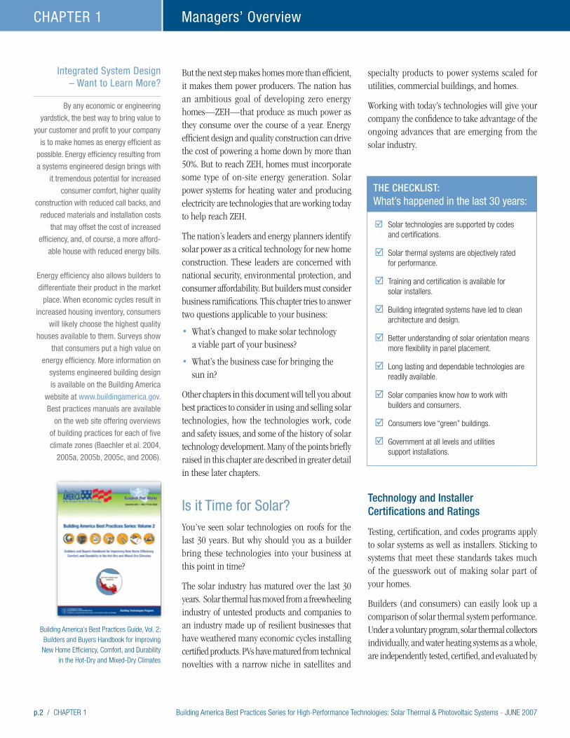
Building America’s Best Practices Guide, Vol. 2: Builders and Buyers Handbook for Improving New Home Efficiency, Comfort, and Durability
in the Hot-Dry and Mixed-Dry Climates
Building America Best Practices Series for High-Performance Technologies: Solar Thermal & Photovoltaic Systems - JUNE 2007 CHAPTER 1 / p.3
Managers’ Overview CHAPTER 1
the Solar Rating and Certifica-tion Corporation (SRCC). The SRCC provides system comparisons on a selected state basis. Ratings, product information, and educational materials are available at the SRCC website: www.solar-rating.org. See Chapter 3 for more information.
The California Energy Commissions (CEC) lists photovoltaic modules and inverters eligible for its incentives at www.consumerenergycenter.org/erprebate/equipment.html. PV system instal-lation is governed by the National Energy Code and components are UL™ listed.
The North American Board of Certified Energy Practitioners (NABCEP) offers solar thermal and PV installer certifications. For more information, including requirements, costs, and prerequisites, visit: www.nabcep.org/pv_installer.cfm.
The Interstate Renewable Energy Council (IREC) works to assure the competency and expertise of instructors, training programs, and continuing education classes emphasizing renew-able energy, including solar applications. For a complete listing of renewable energy courses by state or technology, go to the IREC web site at: www.irecusa.org.
“We are making homes that will last
easily 100 years, because we are
concerned about durability too. Many of
things that make a home more energy
efficient also make it last longer—making
it more weather resistant, keeping out
humidity and dampness problems.” Mark Bergman, owner of Tindall Homes in Columbus, New Jersey
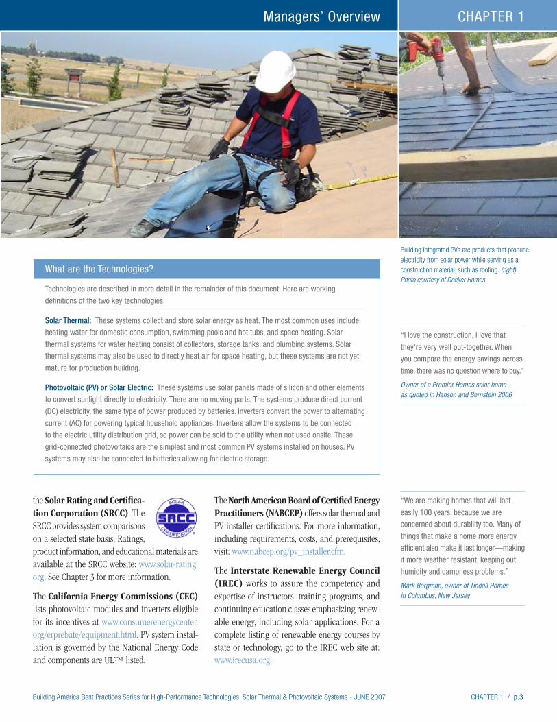
Building Integrated PVs are products that produce electricity from solar power while serving as a construction material, such as roofing. (right) Photo courtesy of Decker Homes.
What are the Technologies?
Technologies are described in more detail in the remainder of this document. Here are working
definitions of the two key technologies.
Solar Thermal: These systems collect and store solar energy as heat. The most common uses include
heating water for domestic consumption, swimming pools and hot tubs, and space heating. Solar
thermal systems for water heating consist of collectors, storage tanks, and plumbing systems. Solar
thermal systems may also be used to directly heat air for space heating, but these systems are not yet
mature for production building.
Photovoltaic (PV) or Solar Electric: These systems use solar panels made of silicon and other elements
to convert sunlight directly to electricity. There are no moving parts. The systems produce direct current
(DC) electricity, the same type of power produced by batteries. Inverters convert the power to alternating
current (AC) for powering typical household appliances. Inverters allow the systems to be connected
to the electric utility distribution grid, so power can be sold to the utility when not used onsite. These
grid-connected photovoltaics are the simplest and most common PV systems installed on houses. PV
systems may also be connected to batteries allowing for electric storage.
“I love the construction, I love that
they’re very well put-together. When
you compare the energy savings across
time, there was no question where to buy.” Owner of a Premier Homes solar home as quoted in Hanson and Bernstein 2006

p.4 / CHAPTER 1 Building America Best Practices Series for High-Performance Technologies: Solar Thermal & Photovoltaic Systems - JUNE 2007
Managers’ Overview CHAPTER 1
Architecture, Design, and Orientation
Perhaps the biggest breakthrough in residential solar systems is in the area of buildings integration. Emerging in the last five years are PVs that can be installed in some roofing systems to make them nearly invisible. Some PVs actually become part of the roof rain-shedding system. Some PV and solar thermal systems are mounted very near—and paral-lel to—the roof at nearly all standard roof pitches. Visually, these systems appear like skylights.
Thin film photovoltaics can be adhered directly to the flat part of raised seam metal roofs and do not change the roof profile. Efficiencies of thin film products are about half those of silicon-crystal arrays; however, the costs per watt are about the same. Researchers believe the potential for increas-ing thin film efficiency is tremendous.
Solar thermal systems have become better pack-aged. Many manufacturers package the majority of valves, sensors, and controllers that need to go inside the house on compact boards or within housings to provide clean, uncluttered appearances in utility areas.
Research shows that more architectural freedom exists for lot placement and solar exposure. Facing due south is best, but little efficiency is lost when either type of solar system is rotated towards the
east or west, within reasonable bounds. Western exposure can be helpful for PVs to assist with utility peak load reduction.
Business Services
As solar systems have become better integrated with house design and visual appeal, solar businesses are becoming better integrated in the building industry. Solar companies have become adept at working with home builders and consumers. Some PV companies provide ongoing web-based monitoring of PV electric output, notifying consum-ers if problems arise. The best solar companies understand how:
• community development is staged,
• to coordinate with other trades,
• to reduce costs through bulk materials purchase, delivery, and installation.
Government and Utility Action
Government at all levels supports solar initiatives. In some areas local governments are providing preferential treatment of permit applications for builders who include solar technologies in their homes. Utilities provide incentive payments for both solar system types and will often buy back photovoltaic electricity not consumed on site.
“We don’t limit ourselves to putting
these tiles on the backs of our houses.
We put tiles on the front, back, or sides
of the houses, wherever they will get the
most solar gain. They blend in so well
with the cement tiles that buyers have
no objection to seeing them. You almost
can’t tell they’re there.”
“We had no difficulty at all working solar
into the production schedule. The solar
installation does not interfere with any
other critical path in the construction
process. It really doesn’t add any time
for installation.”
Mark Fischer, Senior Vice President at Grupe,
a California-based production builder
Although visible, solar thermal systems that sit above the roof have low silhouettes and
resemble skylights.

Building America Best Practices Series for High-Performance Technologies: Solar Thermal & Photovoltaic Systems - JUNE 2007 CHAPTER 1 / p.5
Managers’ Overview CHAPTER 1
State governments and public benefit programs often provide incentives and tax credits. The federal government is currently providing tax credits. In combination, government and utility programs may pay a sizable portion of a solar system purchase price.
Along with incentives, jurisdictions are also consid-ering code changes and programs to encourage
solar development. Austin, Texas, is discussing possible code requirements to make all homes solar capable by 2015. California’s New Solar Home Partnership will require in 2011 that production builders offer PV systems to their customers or install equivalent PV systems elsewhere. The Solar Ready chapter describes measures that help make homes ready to accept solar technology after construction is complete.
Examples of Local Government Permit Incentives
Scottsdale, AZ All qualified green building projects receive fast track plan review service.
www.scottsdaleaz.gov/greenbuilding/Incentives.asp
San Diego County, CA The County does not charge for the building permit and plan check of residential photovoltaic systems.
www.sdcounty.ca.gov/dplu/greenbuildings.html
Marin County, CA The incentives include waiver of the Title 24 energy fee and fast-track permit processing.
www.co.marin.ca.us/depts/CD/main/comdev/advance/best/incentive.cfm
Why Utilities Care About Solar Energy
Electric utilities care about ZEHs and solar energy for two reasons:
First, if it can be acquired cost effectively, solar energy is a non-polluting source of power equivalent to other sources such as energy efficiency or coal-fired generators. This is the key motivation for solar thermal programs at Lakeland Electric in Florida and the Sacramento Municipal Utility District in California.
Second, PV systems can be designed to be especially good at reducing peak demand. Peak demand is the time of day when the most energy is required and it is most expensive for the utility to purchase.
-1.0012 1 2 3 4 5AM PM
6 7 8 9 10 11 12 1 2 3 4 5 6 7 8 9 10 11
500
1,000
1,500
2,000
2,500
3,000
-0.5
-0.0
0.5
1.0
1.5
2.0
2.5
3.0
3.5 kW
Avg. High Temp = 98°F
Average 15 Minute Interval Peak Demand ZEH vs. Non-ZEH July, 2005
Avg. Min Temp = 65°FSystem Peak MWAverage of ZEH Net Grid Load (kW)Average of Power Produced by PV (kW)Average of Non-ZEH Net Grid Load (kW)
California’s New Solar Homes Partnership
California’s New Solar Home Partner-
ship… “is intended to transform the
new home industry and have consumers
ask for solar in their new home to lower
their energy bills,” said Energy Commis-
sion Chairman Jackalyne Pfannenstiel.
A new home that qualifies for the New
Solar Homes Partnership will be at least
15 percent more efficient than Title 24,
California’s current energy efficiency
standards. Qualified homes will include
Energy Star-rated appliances, and a
roof top PV system with a 10-year
warranty to protect against defective
workmanship or system and component
breakdown. The program also includes
incentive payments.
The partnership encourages builders to
install PV systems on new homes as a
standard feature, just like granite coun-
tertops. Beginning in 2011, builders will
be required to offer solar as a standard
feature in new home developments of
50 or more. Currently, California has
over 23,000 photovoltaic system instal-
lations, of which, 1,500 are installed on
new homes.
The New Solar Homes Partnership is
a component of the California Solar
Initiative, which was signed into law in
2006. The California Energy Commission
and the Public Utilities Commission each
administer coordinated elements of the
Initiative. For updates about the New
Solar Homes Partnership and a copy
of the program guidebook, visit
the Go Solar California website at:
www.gosolarcalifornia.ca.gov.
Solar thermal meter used by Lakeland Electric. Photo courtesy of Jeff Curry of Lakeland Electric.
In addition to saving about 60% of a typical home’s energy bill, ZEHs at Premier Gardens substantially reduce peak demand. In July 2005 when Sacramento experienced its hottest July on record, Premier Gardens had peak demands that were 75% less than typical new houses at 4.5 kW peak load.
p.6 / CHAPTER 1 Building America Best Practices Series for High-Performance Technologies: Solar Thermal & Photovoltaic Systems - JUNE 2007
Managers’ Overview CHAPTER 1
Reliability and Efficiency
Solar thermal technologies are well proven genera-tors of hot water. In Hawaii, the most expansive solar water heating market in the U.S., the Hawai-ian Electric Company has found that with nearly 120,000 installations, less than 0.2% of systems have resulted in warranty claims (2 in 1,000). Turning that number around, over 99.8% of solar water heater systems perform without a consumer claim (Richmond 2005).
As photovoltaic modules have proven their reliabil-ity, warranty periods have increased, with 25-year warranties common since 1999 (Wohlgemuth 2003). Based on a world-wide assessment, the PV module failure rate is down to 0.01% (1 in 10,000) per year (IEA 2002).
Inverters form the gateway between the photovoltaic system and the electric utility grid. Modern inverters have reached efficiency levels near 95% at convert-ing DC power to AC power. Research suggests that newer inverters in Europe last 10 to 15 years (IEA 2002; Wilk 2002; Nordmann, Jahn, and Nasse 2004). New inverters in the U.S. will be released in 2008 that carry a ten-year warranty.
Another recent development expected to further improve PV performance is plug-and-play connec-tors yielding more reliable in-field wire connections (IEA 2005).
European experience has shown that overall system performance as a percentage of power production in comparison to rated capacity (including modules, inverters, mounting, and wiring) rose from about 60% in systems installed before 1995 to 80% in systems installed after 1995 (Nordmann, Jahn, and Nasse 2004). Performance at 80% of rated capacity continues to be a reasonable expectation for PV systems.
The Business CaseSolar thermal technology is mature and reliable and is now being packaged in ways that make it more easily incorporated into production building. Anticipated solar thermal technologies are expected
to push costs down. PV has gained consumer, government, and utility attention and is emerging as a reliable product that easily fits into home designs. So, technically, these products are available and can be strong additions to home offerings.
This section now looks at the business case for solar technologies and opportunities for a comparative advantage for builders’ business performance. As noted earlier, energy efficiency and systems integrated design are important parts of the ZEH package. By themselves, those elements make good business sense and they should be used by all builders to increase building performance and consumer value. The business case for adding solar to your product mix requires looking at how well homes equipped with solar sell, how consumers respond to solar communities, other benefits that may result from consumer responses or incen-tives, and competitive advantages that accrue to production builders.
From a national security, consumer value, company profit, or any other perspective, energy efficiency makes sense. But today’s ZEH homes takes energy efficiency three steps further:
• First, by producing renewable energy, solar technologies give consumers a positive contribution back to their community. A common benefit identified by consumers is environmental protection.
• Second, even though it is no longer an obvious add-on to a house, solar technologies are visible badges demonstrating lifestyle choices and quality construction; and
• Third, while PV is costly alone, in combina-tion with 30% to 40% improvements in energy efficiency, it provides a positive cash flow in combination with utility bills and mortgage payments.
Lesson Learned from ZEH Communities
Consumers at every price point embrace ZEH when they have the opportunity. California has the most developed housing market for ZEHs with the most consumers responding to product offerings.
“We all want to make money but at some
point as a society we have to evaluate
what we are doing. Our homes save more
than 60% of power over houses built to
the state code. Over the lifetime of the
house, our (Tindall) homes will save more
in energy costs than the purchase price
of the house. If we all did this, we could
make a big difference.”
Mark Bergman, owner of Tindall Homes in Columbus New Jersey.
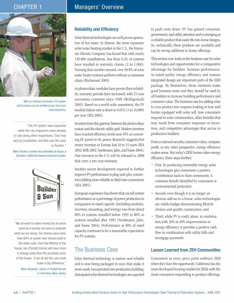
With an internet connection, PV system performance can be verified at any time from
most anywhere.
“The PV system was inspected
while the city inspectors were already
on site doing other inspections. That may
vary by jurisdiction, but that was the case
in Rocklin.”
Mark Fischer, a senior vice president at Grupe, a Stockton, California-based production builder.
Building America Best Practices Series for High-Performance Technologies: Solar Thermal & Photovoltaic Systems - JUNE 2007 CHAPTER 1 / p.7
Managers’ Overview CHAPTER 1
Homebuyer quotes from SheaHomes:
“It’s best to integrate the solar electric
system into the entire home purchase
rather than having it offered as an
option in a piecemeal way. It should
all be rolled into one.”
“We wanted to get the house because
the system was already there. We didn’t
have to decide about it. We’re glad it is
here. We’re lucky to have the PV.”
“We thought about offering solar as an
option, but I like the way it makes us
unique, and I didn’t think it would be
successful as an option based on how
other builders have done with it. When
you make it standard, buyers accept it
without hesitation. Once you decide to
do a whole development with solar, its
easy to work it into your schedule, and
to train your subcontractors. And we
decided it was the right thing to do.”
Mark Fischer, a senior vice president at Grupe, a Stockton, California-based production builder
Building America has worked with builders in many ZEH projects in California. Four ZEH commu-nities with 100 to 300 houses each offer many lessons. All four builders outsold their competition. Consumer attitudes and energy performance have been documented at two of the projects (Farhar and Coburn 2006; Coburn, Farhar, and Pratsch 2006; Baccei 2006). And, the builder of a third community presented business implications at the 2007 PCBC Builders conference in San Fracisco. A more detailed description of market studies and sales strategies is found in Chapter 2: Solar Sells. Some of the findings are summarized here.
• ZEH sells faster – All four ZEH communities report selling homes at a faster clip than nearby projects. One builder started selling in early 2006 and is outselling its competitors by over 2.5 times.
• Selling homes faster saves the builder money – Grupe Homes has reported the financial impacts from an increased sales rate. Grupe achieved a sales rate of 4.6 home sales per month versus 1.9 for their competitors, a rate 2.5 times faster than competing projects in the Whitney Ranch Master Plan. Grupe has calculated that its increased costs of $2.6 million due to energy
efficiency, solar PV, and green features, would be paid off in less than 9 months due to the greater sales rate.
• Consumers are interested – Surveys show consumer interest in PV and solar thermal tech-nologies. In a survey of Colorado homeowners conducted in 2000, 57% were favorable to install-ing PV on existing houses and 16% were highly motivated, even when informed about costs (Farhar and Coburn 2000). National studies, and detailed analyses of specific communities, show that consumers are willing to purchase energy efficient and solar technologies as long as costs are offset by utility savings.
• Educate consumers – Builders are in a strong position to sell solar technologies, but must inform consumers. In one survey, over three-fourths of all respondents indicated that if their builder had recommended solar thermal they would have either seriously considered it or wanted to learn more.
• Strive for 50% savings – One observation of ZEH projects is that consumers respond to achieving at least 50% reductions in energy consumption through a combination of energy efficiency and solar technologies.
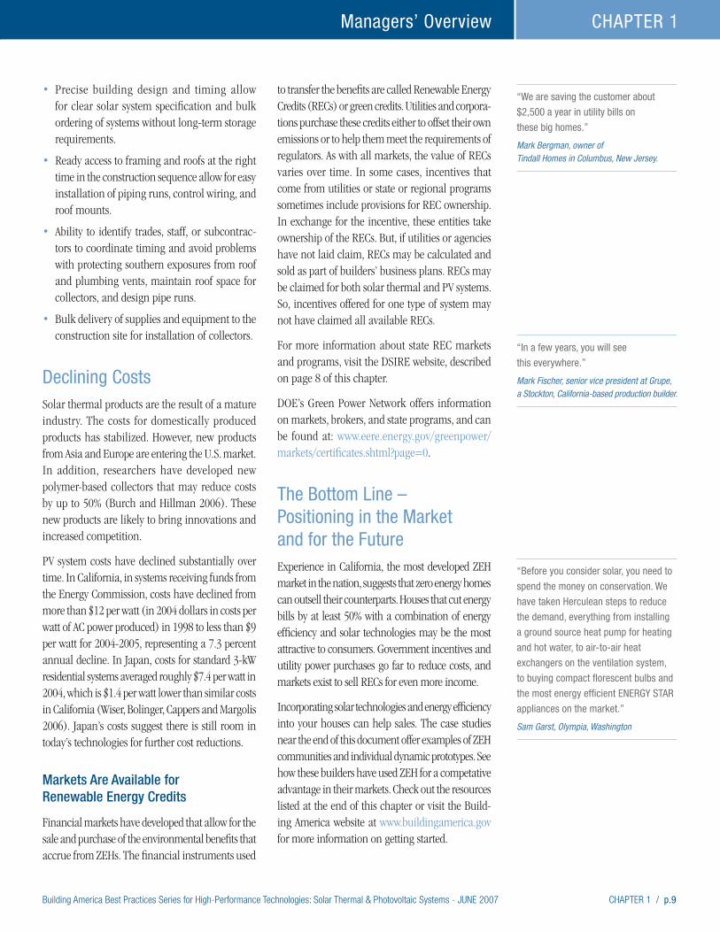
Premier Gardens solar-powered homes. Photo courtesy of the Sacramento Municipal Utility District.
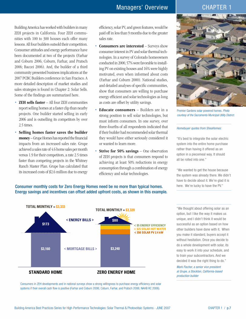
STANDARD HOME ZERO ENERGY HOME
$3,160 $3,240
$173
TOTAL MONTHLY = $3,333TOTAL MONTHLY = $3,320
< MORTGAGE BILLS >
< E< $5 ENERGY EFFICIENCY< $25 SOLAR HOT WATER< $50 SOLAR PV 2.4 kW
NERGY BILLS > $80
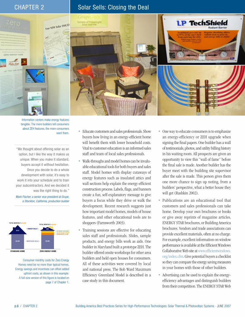
Consumer monthly costs for Zero Energy Homes need be no more than typical homes. Energy savings and incentives can offset added upfront costs, as shown in this example.
Consumers in ZEH developments and in national surveys show a strong willingness to purchase energy efficiency and solar systems if their overall cash flow is positive (Farhar and Coburn 2006; Coburn, Farhar, and Pratsch 2006; NAHB RC 2006).
p.8 / CHAPTER 1 Building America Best Practices Series for High-Performance Technologies: Solar Thermal & Photovoltaic Systems - JUNE 2007
Managers’ Overview CHAPTER 1
• ZEH consumers are satisfied – Market studies of Premier Gardens community has found that ZEH consumers tend to be higher educated and more satisfied than a neighboring community. Other market research has shown that highly satisfied consumers tend to recom-mend their builder much more frequently than other customers.
• Incorporate solar into standard package – A detailed study was done of homeowner attitudes in a ZEH community in San Diego built by SheaHomes (Farhar and Coburn 2006; Coburn, Farhar, and Pratsch 2006) that includes both solar thermal and PV. The builder in this project concluded that it is more profitable to offer solar systems as standard features, not as an optional package.
• Consumers prefer standard package – Consumers also have shown a preference for making both PV and solar thermal standard features. Some SheaHomes customers noted that it took much of the guesswork out of their purchase. Other survey findings support this conclusion. One study found that: “Consumers are much more likely to purchase a solar system from the builder as the home is being built because they view the installation as being much more simple and safe in terms of the roof warranty during the construction stage (Ghent and Keller 1999).”
• ZEH homes appreciate more – An impor-tant piece of economic data for homeowners is value appreciation. For many consum-ers, their home is their largest investment. SheaHomes went up in value by over 55%, compared to an increase of about 45% for a nearby community. The original cost of a SheaHomes house was about $40,000 less than a comparison home but ended up at slightly higher resale value (Farhar & Coburn 2006).
Production Builder Advantages
Successful production builders excel in designing homes, developing construction processes, and selecting materials to drive down costs and increase
consumer value. These traits apply to installing solar and energy efficiency features in new homes. And production builders have tremendous advantages in planning and structural access. These features are described in Chapters 3 and 4.
Production builder advantages show up in lower solar equipment costs. Studies of California’s PV incentive programs show that systems installed in large new home developments are, on average, far more economical than retrofitted systems (Wiser, Bolinger, Cappers and Margolis 2006). Systems installed (or planned for installation) under the California Energy Commission’s program in large new residential developments (totaling 1,946 systems) have costs about 13% less ($1.2/Watt) on average, compared to the general retrofit market (in 2004 dollars in costs per watt of AC power produced). Similarly, 340 installations used in affordable housing applications, which often involve new construction and presumably enable bulk system installation, show costs that are 21% ($1.9/Watt) lower than the general retrofit market.
Researchers working with solar thermal have suggested that new home production builders could reduce water heating system costs by up to 40% in comparison to retrofit markets (Burch 2005). These researchers are working on new polymer technologies that could bring costs down by up to another 50%.
Another builder advantage is the availability of consumer financing in the form of a mortgage. In the Colorado survey described earlier, responders identified utility bills and mortgage payments as preferred methods of paying for PV systems. Consumers in ZEH developments and in national surveys show a strong willingness to purchase energy efficiency and solar systems if their overall cash flow is positive (Farhar and Coburn 2006; Coburn, Farhar, and Pratsch 2006; NAHB RC 2006). In other words, they are interested in ZEH features, as long as their increased mortgage payment is offset by reduced utility costs.
Advantages production builders bring to ZEH include:
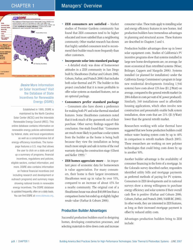
Desire More Information on Solar Incentives? Visit
the Database of State Incentives for Renewable
Energy (DSIRE)
Established in 1995, DSIRE is
maintained by the North Carolina
Solar Center (NCSC) and the Interstate
Renewable Energy Council (IREC). This
online database contains information on
renewable energy policies administered
by federal, state, and local organizations
as well as a comprehensive list of
energy-efficiency incentives. The home-
page features a U.S. map that allows
the user to click on a state and pull
up a summary of programs, financial
incentives, regulations and policies,
eligible sectors, contact information, and
more. DSIRE also contains information
on Federal financial incentives (not
including research and development or
outreach programs) and summary maps
showing national trends in renewable
energy incentives. The DSIRE database
is updated frequently, often on a daily basis.
You can find DSIRE at www.dsireusa.org.
Building America Best Practices Series for High-Performance Technologies: Solar Thermal & Photovoltaic Systems - JUNE 2007 CHAPTER 1 / p.9
Managers’ Overview CHAPTER 1
“In a few years, you will see
this everywhere.”
Mark Fischer, senior vice president at Grupe, a Stockton, California-based production builder.
• Precise building design and timing allow for clear solar system specification and bulk ordering of systems without long-term storage requirements.
• Ready access to framing and roofs at the right time in the construction sequence allow for easy installation of piping runs, control wiring, and roof mounts.
• Ability to identify trades, staff, or subcontrac-tors to coordinate timing and avoid problems with protecting southern exposures from roof and plumbing vents, maintain roof space for collectors, and design pipe runs.
• Bulk delivery of supplies and equipment to the construction site for installation of collectors.
Declining CostsSolar thermal products are the result of a mature industry. The costs for domestically produced products has stabilized. However, new products from Asia and Europe are entering the U.S. market. In addition, researchers have developed new polymer-based collectors that may reduce costs by up to 50% (Burch and Hillman 2006). These new products are likely to bring innovations and increased competition.
PV system costs have declined substantially over time. In California, in systems receiving funds from the Energy Commission, costs have declined from more than $12 per watt (in 2004 dollars in costs per watt of AC power produced) in 1998 to less than $9 per watt for 2004-2005, representing a 7.3 percent annual decline. In Japan, costs for standard 3-kW residential systems averaged roughly $7.4 per watt in 2004, which is $1.4 per watt lower than similar costs in California (Wiser, Bolinger, Cappers and Margolis 2006). Japan’s costs suggest there is still room in today’s technologies for further cost reductions.
Markets Are Available for Renewable Energy Credits
Financial markets have developed that allow for the sale and purchase of the environmental benefits that accrue from ZEHs. The financial instruments used
to transfer the benefits are called Renewable Energy Credits (RECs) or green credits. Utilities and corpora-tions purchase these credits either to offset their own emissions or to help them meet the requirements of regulators. As with all markets, the value of RECs varies over time. In some cases, incentives that come from utilities or state or regional programs sometimes include provisions for REC ownership. In exchange for the incentive, these entities take ownership of the RECs. But, if utilities or agencies have not laid claim, RECs may be calculated and sold as part of builders’ business plans. RECs may be claimed for both solar thermal and PV systems. So, incentives offered for one type of system may not have claimed all available RECs.
For more information about state REC markets and programs, visit the DSIRE website, described on page 8 of this chapter.
DOE’s Green Power Network offers information on markets, brokers, and state programs, and can be found at: www.eere.energy.gov/greenpower/markets/certificates.shtml?page=0.
The Bottom Line – Positioning in the Market and for the FutureExperience in California, the most developed ZEH market in the nation, suggests that zero energy homes can outsell their counterparts. Houses that cut energy bills by at least 50% with a combination of energy efficiency and solar technologies may be the most attractive to consumers. Government incentives and utility power purchases go far to reduce costs, and markets exist to sell RECs for even more income.
Incorporating solar technologies and energy efficiency into your houses can help sales. The case studies near the end of this document offer examples of ZEH communities and individual dynamic prototypes. See how these builders have used ZEH for a competative advantage in their markets. Check out the resources listed at the end of this chapter or visit the Build-ing America website at www.buildingamerica.gov for more information on getting started.
“We are saving the customer about
$2,500 a year in utility bills on
these big homes.” Mark Bergman, owner of Tindall Homes in Columbus, New Jersey.
“Before you consider solar, you need to
spend the money on conservation. We
have taken Herculean steps to reduce
the demand, everything from installing
a ground source heat pump for heating
and hot water, to air-to-air heat
exchangers on the ventilation system,
to buying compact florescent bulbs and
the most energy efficient ENERGY STAR
appliances on the market.” Sam Garst, Olympia, Washington

p.10 / CHAPTER 1 Building America Best Practices Series for High-Performance Technologies: Solar Thermal & Photovoltaic Systems - JUNE 2007
Managers’ Overview CHAPTER 1
Builders that pursue zero energy homes are focusing on the future. Their experience with PV and solar thermal technologies, and the systems integrated building design approach, allows them to confidently evaluate and incorporate new technologies as they emerge in the marketplace. Solar technologies and high performance homes position builders in the market as innovative and value-focused.
Resources and References
Baccei, Bruce. 2006. “Impacts of Zero Energy Homes on Buyers and Owners.” Solar 2006 Conference Proceedings, edited by R. Campbell-Howe. American Solar Energy Society, Boulder, CO.
Baechler, Michael and Pat Love. 2004. Building America Best Practice Series: Volume 1 – Builders and Buyers Handbook for Improving New Home Efficiency, Comfort, and Durability in the Hot and Humid Climate, Version 1. U.S. Department of Energy, Washington, D.C. www.buildingamerica.gov.
Baechler, Michael, Z. Todd Taylor, Rosemarie Bartlett, Theresa Gilbride, Marye Hefty, Heidi Steward, and Pat Love. 2005a. Building America Best Practice Series: Volume 4 – Builders and Buyers Handbook for Improving New Home Efficiency, Comfort, and Durability in the Mixed Humid Climate, Version 1. U.S. Department of Energy, Washington, D.C. www.buildingamerica.gov.
Baechler, Michael, Z. Todd Taylor, Rosemarie Bartlett, Theresa Gilbride, Marye Hefty, Heidi Steward, and Pat Love. 2005b. Building America Best Practice Series: Volume 3 – Builders and Buyers Handbook for Improving New Home Efficiency, Comfort, and Durability in the Cold and Very Cold Climates, Version 1. U.S. Department of Energy, Washington, D.C. www.buildingamerica.gov.
Baechler, Michael, Z. Todd Taylor, Rosemarie Bartlett, Theresa Gilbride, Marye Hefty, Pat Love. 2005c. Building America Best Practice Series: Volume 2 – Builders and Buyers Handbook for Improving New Home Efficiency, Comfort, and Durability in the Hot-Dry and Mixed Dry Climates, Version 1. U.S. Department of Energy, Washington, D.C. www.buildingamerica.gov.
Baechler, Michael, Z. Todd Taylor, Rosemarie Bartlett, Theresa Gilbride, Marye Hefty, Heidi Steward, and Pat Love. 2006. Building America Best Practice Series: Volume 5 – Builders and Buyers Handbook for Improving New Home Efficiency, Comfort, and Durability in the Marine Climate, Version 1. U.S. Department of Energy, Washington, D.C. www.buildingamerica.gov.
Burch, Jay and Tim Hillman. 2005. “Cold-Climate Solar Domestic Water Heating Systems: Life-Cycle Analyses and Opportunities for Cost Reduction.” Solar 2005 Conference Proceedings, edited by R. Campbell-Howe. American Solar Energy Society, Boulder, CO.
California New Solar Home Partnership information can be found at www.gosolarcalifornia.ca.gov.
Coburn, Timothy, Barbara Farhar, and Lew Pratsch. 2006. “Comparative Analysis of Utility Consumption and Costs of Near-ZEHs and Comparison Homes in California.” In Proceeding of the 2006 ACEEE Summer Study on Energy Efficiency in Buildings, Washington, D.C.
“We are selling at a pace that is
double that of our competition at
Whitney Ranch. If just 20% of this
increased sales rate is due to the solar
and green features, then the Grupe
Green program has paid for itself.”
Mark Fischer, senior vice president at Grupe, a Stockton, California-based production builder.

Building America Best Practices Series for High-Performance Technologies: Solar Thermal & Photovoltaic Systems - JUNE 2007 CHAPTER 1 / p.11
Managers’ Overview CHAPTER 1
DSIRE is a website with information about incentives for renewable energy and energy efficiency. Available at www.dsireusa.org.
Farhar, B.C. and T.C. Coburn. 2006. A New Market Paradigm for Zero-Energy Homes: The Comparative San Diego Case Study. NREL/TP-550-38304-01. Prepared by the National Renewable Energy Laboratory for the U.S. Department of Energy. www.nrel.gov/docs/fy07osti/38304-01.pdf
Hanson, M. and M. Bernstein. 2006, The Role of Energy Efficiency in Homebuying Decisions: Results of Initial Focus Group Discussions. WR-352-CON, Rand Corp.
Farhar, Barbara, and Timothy Coburn. 2000. A Market Assessment of Residential Grid-Tied PV Systems in Colorado. NREL/TP-550-25283. National Renewable Energy Laboratory, Golden, CO.
Ghent, P. and C. Keller. 1999. A Comprehensive Review of Market Research on Solar Water Heaters.NREL/SR-550-27123. Prepared for the National Renewable Energy Laboratory by Focus Marketing Services, Westlake Village, CA.
International Energy Agency (IEA). 2005. Trends in Photovoltiac Applications: Survey Report of Selected IEA Countries Between 1992 and 2004. IEA-PVPS T1-14:2005.
International Energy Agency (IEA). 2002. Reliability Study of Grid Connected PV Systems Field Experience and Recommended Design Practice. Report IEA-PVPS T7-08: 2002, Edited by Hermann Laukamp, www.iea-pvps.org/products/download/rep7_08.pdf.
National Association of Home Builders Research Center (NAHBRC). 2006. The Potential Impacts of Zero Energy Homes. Prepared for the National Renewable Energy Laboratory, Golden, CO.
Nordmann, Thomas, Ulrike Jahn and Wolfgang Nasse. 2004. “Performance of PV Systems Under Real Conditions.” European Workshop on Life Cycle Analysis and Recycling of Solar Modules.
Richmond, Ron. 2005. Presentation at the 2005 Solar Power Conference, October 5-7, 2005, Washington, D.C.
Szaro, Jennifer, Carol Emrich, William Wilson, and James Dunlop. 2002. Photovoltaic Systems Performance and Reliability Database. Southeast Regional Experiment Station – Florida Solar Energy Center, Cocoa, FL.
Wilk, Heinrich. 2002. “Reliability of PV Systems in Austria, Lessons Learned.” In Operational Performance, Reliability and Promotion of Photovoltaic Systems: Proceedings of October 2001 Workshop. IEA-PVPS T2-03:2002. Prepared by Jahn Ulride and Wolfgang Nasse. International Energy Agency (IEA).
Wiser, Ryan, Mark Bolinger, Peter Cappers, and Robert Margolis. 2006. Letting the Sun Shine on Solar Costs: An Empirical Investigation of Photovoltaic Cost Trends in California. LBNL-59282, NREL/TP-620-39300. Prepared for the U.S. DOE by Lawrence Berkeley National Laboratory, Berkeley, CA, and the National Renewable Energy Laboratory, Golden, CO. Available at http://eetd.lbl.gov/EA/EMP.
Wohlgemuth, John H. 2003. “Long Term Photovoltaic Module Reliability.” NCPV and Solar Program Review Meeting 2003. NREL/CD-520-33586, pp. 179-182. National Renewable Energy Laboratory, Golden, CO.
Building America Best Practices Series for High-Performance Technologies: Solar Thermal & Photovoltaic Systems - JUNE 2007 CHAPTER 2 / p.1
High-Performance Home Technologies: Solar Thermal & Photovoltaic Systems
Chapter 2. Solar Sells: Closing the Deal
Building America Best Practices Series
Solar can be a great selling tool if sales staff know how to use it: “If you are going to put it in, be prepared to train your whole organization on why it’s a good deal, especially sales staff. You have to train them so that they can tell potential buyers why solar is so great.”
Mark Fischer, a senior vice president at Grupe, a Stockton, California builder
Most real estate marketing professionals try to link homebuyers with properties that meet consumer expectations. With ZEH homes, sales staff must help buyers expand their expectations and raise the bar in expected home performance. Consumers select products and new innovations that offer benefits they desire. When selling ZEH, marketers must help consumers understand these benefits.
This chapter presents information that explains why consumers care about energy costs and efficiency. It examines the advantages that production builders have for installing solar thermal and photovoltaic systems. And this chapter examines how some builders are selling ZEH homes.
Sales display in the education center at the “Zero Energy” Fallen Leaf community in Sacramento, California.
“Solar is definitely making us more
competitive; there is no doubt about
that. People just need to be better
educated about it (solar). For the most
part, most people don’t understand the
true benefits.” Sheri Gage, sales manager at Premier Meadows, a community in California
“We sold 23 of our first 30 homes in
the first three months, even though the
market in Sacramento is very slow right
now; it is the slowest housing market in
the country. Our project is doing better
than most of our competitors.” Mark Fischer, a senior vice president at Grupe, a California-based production builder producing 200 to 300 homes per year
“It is an opportunity to set ourselves
apart as a small builder. The market will
be wanting more energy efficiency as
time goes on and we want to stay
ahead of it.” John Ralston, Vice President of Sales and Marketing for Roseville, California-based Premier Homes
Builders’ Brief
• Consumers select products and new
innovations that offer benefits they desire.
• Consumers care about value and are willing
to pay for it.
• Real-world experience shows efficiency and
ZEH contribute to customer satisfaction.
• Highly satisfied customers refer their builders
to twice as many people.
• Energy reductions greater than 50% seem
to “close the deal” for many consumers.
• Homeowners brag about their ZEH and
low utility bills.
• Solar is a tangible badge of efficiency,
innovation, and green building.
• Educate buyers with green showrooms.
Installers’ Brief
• PV and solar thermal companies may have more
experience than the builder with ZEH technologies
and can help educate sales staff and consumers.
• Sales staff must tell the ZEH story. Provide
them with materials to help educate
consumers about the benefits of energy
efficiency and solar technologies.
• Provide sample products to put in showrooms.
• Produce brochures, videos, and signs that
show consumers how they will save money, be
more comfortable, and help the environment.
• Collect testimonials that marketers can use to
educate consumers.
• Provide materials for the homeowners
manuals that help consumers understand and
maintain their system.
p.2 / CHAPTER 2 Building America Best Practices Series for High-Performance Technologies: Solar Thermal & Photovoltaic Systems - JUNE 2007
Solar Sells: Closing the Deal CHAPTER 2
Efficiency, Comfort, and Consumer SatisfactionWouldn’t it be great if, for every home you sold, you added a new sales associate to bring in more leads? That is what energy efficiency can do. Happy customers will sell your products for you. And energy-efficient homes make happy customers. Compared to standard homes, energy-efficient homes cost less to own, are more comfortable to live in, and require less maintenance. Customers like these benefits and it contributes to their satisfaction.
Market research shows:
• 10% to 30%, and sometimes more, of builders’ sales come from referrals (Farnsworth 2003).
• J.D. Power found that truly delighted home buyers (those rating their builders a 10 on a 10-point scale) recommend their builder to nearly twice as many people as the average new-home buyer ( J.D. Power 2005).
• Energy efficiency is the number one upgrade sought by homebuyers of new homes (Professional Builder Magazine 2001).
• Nearly 90% of new homebuyers are willing to spend more for energy efficiency ( Johnston 2000 and NAHB 2002).
• Buyers rate energy efficiency as a home builder’s most important product-related reason for referring new customers (Professional Builder Magazine 2003).
Solar Technologies: The Rest of the Story
Energy efficiency is important to consumers, but it is only half the story of a ZEH. Consumers respond well to solar technologies that make up the other part of the story. Chapter 1: Managers’ Overview summarizes a variety of market studies and lessons learned from ZEH communities. The bottom line is that ZEH communities outsell their neighboring non-ZEH communities. And, even when neighboring houses are energy efficient, consumers in ZEH communi-ties are more satisfied with their home purchase (Baccei 2006).
Market research suggests that consumers are interested if asked about PV technology. A survey of Colorado residents conducted in 2000 found that 57% were favorable to installing PV on existing houses (Farhar and Coburn 2000). 16% of the surveyed homeowners were found to be highly motivated to purchase PV systems.
But, sales staff need to inform consumers about energy efficiency and solar technologies. After learning about current technology and product options, for example, consumers are more likely to consider purchasing a solar water heating system (Ghent and Keller 1999). In a study of Phoenix and Las Vegas recent home buyers, the number who said they were extremely or somewhat likely to buy a solar water heater rose from 60% to 74% after an interview session that included showing the consumers photos and a description of solar panels (SMC 1999).
In a national sample survey of recent homebuyers, 78% of the respondents agreed that, if their builders had recommended solar water heating for their new homes, they would have seriously considered it or would have wanted to learn more about it (NAHBRC 2004).
Four ZEH Builders Out Sold Their Competition
California has the most developed housing market for ZEHs. Building America has worked with build-ers in many ZEH projects in California. Four of the largest ZEH communities offer lessons learned in consumer response. Consumer attitudes and energy performance have been documented for two of the projects (Farhar 2006; Baccei 2006). Informal discussions with builders and observations offer insights into the other two communities. Three of these home builders are featured in case studies at the end of this handbook.
“I couldn’t imagine moving [except to
another] solar energy home.”
“Yeah, for us it was the energy package,
first and foremost. And we were pretty
much set on that. That was what made
our decision easier.” Owners of a Premier Homes ZEH home as quoted in focus group study by Hanson, M
and M. Bernstein (2006)
The builder with the top customer
satisfaction rating in the nation in 2003,
Pulte Homes of Phoenix, is a Building
America partner offering ENERGY STAR
qualified homes. Pulte’s Phoenix division
has had one or more positive referrals
from 93% of its homebuyers. In short,
what Pulte has done is bundle energy
efficiency with other attributes valued
by their consumers, such as economic
value, comfort, and quality construction.
“The sales office is actively marketing
the energy efficiency of our homes;
they state it in the first five sentences
to the potential buyer.” John Moynihan New Jersey solar contractor
who works closely with solar home builder Mark Bergman.
Building America Best Practices Series for High-Performance Technologies: Solar Thermal & Photovoltaic Systems - JUNE 2007 CHAPTER 2 / p.3
Solar Sells: Closing the Deal CHAPTER 2
“Solar electric power adds value to the
homes we build. By giving homeowners
the tools they need to generate their
own electricity, we’re enabling them to
save money on their utility bills. We’re
also differentiating our homes in the
marketplace.” John Suppes, President of Clarum Homes, which is building ZEH developments in California and Arizona.
Sales staff receive training at Bob Ward Homes Maximum Efficiency Greenland Model. (Photos courtesy of Joseph Wiehagen of the National Association of Home Builders Research Center.)
The Other Side of the Coin – What Consumers See
The message for selling ZEH is overwhelmingly positive. Energy efficiency technology contributes to
better comfort, more durable construction, and lower energy costs. Solar technologies save money, are a
badge of innovation, and produce power. ZEH are good for the environment and good for national security.
But there is another side to the coin. Consumers see messages all the time that influence their thinking.
These messages relate to climate change, blackouts, rising utility prices, and energy shortages. Here is
a sampling of recent findings and headlines.
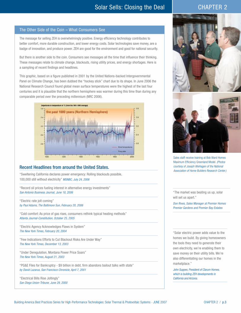
This graphic, based on a figure published in 2001 by the United Nations-backed Intergovernmental
Panel on Climate Change, has been dubbed the “hockey stick” chart due to its shape. In June 2006 the
National Research Council found global mean surface temperatures were the highest of the last four
centuries and it is plausible that the northern hemisphere was warmer during this time than during any
comparable period over the preceding millennium (NRC 2006).
Recent Headlines from around the United States.“Sweltering California declares power emergency: Rolling blackouts possible,
100,000 still without electricity” MSNBC, July 24, 2006
“Record oil prices fueling interest in alternative energy investments” San Antonio Business Journal, June 18, 2006
“Electric rate jolt coming” by Paul Adams, The Baltimore Sun, February 20, 2006
“Cold comfort: As price of gas rises, consumers rethink typical heating methods” Atlanta Journal-Constitution, October 25, 2005
“Electric Agency Acknowledges Flaws in System” The New York Times, February 20, 2004
”Few Indications Efforts to Cut Blackout Risks Are Under Way” The New York Times, December 13, 2003
“Under Deregulation, Montana Power Price Soars” The New York Times, August 21, 2003
“PG&E Files for Bankruptcy - $9 billion in debt, firm abandons bailout talks with state” by David Lazarus, San Francisco Chronicle, April 7, 2001
“Electrical Bills Rise Joltingly” San Diego Union-Tribune, June 29, 2000
“The market was beating us up, solar
will set us apart.” Don Rives, Sales Manager at Premier Homes Premier Gardens and Premier Bay Estates
p.4 / CHAPTER 2 Building America Best Practices Series for High-Performance Technologies: Solar Thermal & Photovoltaic Systems - JUNE 2007
Solar Sells: Closing the Deal CHAPTER 2
SheaHomes, Clarum Homes, Premier Homes, and Grupe Homes all report selling homes at a faster clip than nearby projects. Early in project development, Grupe Homes was outselling their competitors by nearly 2-to-1 based on internal company reports. In autumn of 2006, they were still selling about 50% faster.
Clarum Home’s absorption rate (the pace at which they sell homes) is about twice the state average. Last year they were outselling the state average by about 66%. In one ZEH community, Clarum planned on a three-year development schedule, but sold out in the first year. This project in Watsonville, California, is the largest ZEH community in the U.S. These findings are based on builder interviews and observations of the California market.
Mark Fischer of Grupe Homes notes that consumers are attracted to achieving at least 50% reductions in energy consumption, achieved through a combina-tion of energy efficiency and solar technologies.
Market studies of Premier Gardens found that solar consumers tended to be higher educated and more satisfied than a neighboring community (Baccei 2006).
Make Solar a Standard Feature
All 306 homes in the SheaHomes development included solar thermal hot water and 120 homes
included PV systems. The builder in this project concluded that it is more profitable to offer solar systems as standard features, not as an optional package. Consumers agreed, noting that making solar a standard feature took much of the guesswork out of their purchase. Based on and analysis of utility bills, energy costs in the SheaHomes commu-nity were 14% to 54% less than the comparison community (Farhar and Coburn 2006).
The SheaHomes result is backed up by a review of marketing studies on solar thermal by Ghent and Keller (1999), who reported that consumers preferred that new home builders offer solar thermal options. One study found that: “Consumers are much more likely to purchase a solar system from the builder as the home is being built because they view the installation as being much more simple and safe in terms of the roof warranty during the construction stage.”
Value Appreciation
For many consumers, their home is their largest investment. SheaHomes went up in value by over 55%, compared to about 45% for a comparison community. The original cost of the SheaHomes houses was about $40,000 less than the comparison homes but ended up at slightly higher resale costs.
Clarum Homes of Palo Alto, CA, is
the builder of the nation’s largest
zero energy homes community, Vista
Montana, with 177 PV powered single-
family homes and 80 PV townhouses in
Watsonville, California, sold out in 2004.
“All 257 homes sold out in the first year
they were on the market (rather than
the three years planned). Prices were
initially advertised as ranging from
$379,000 to $499,000 but some units
sold for as much as $600,000.” John Suppes, President of Clarum Homes
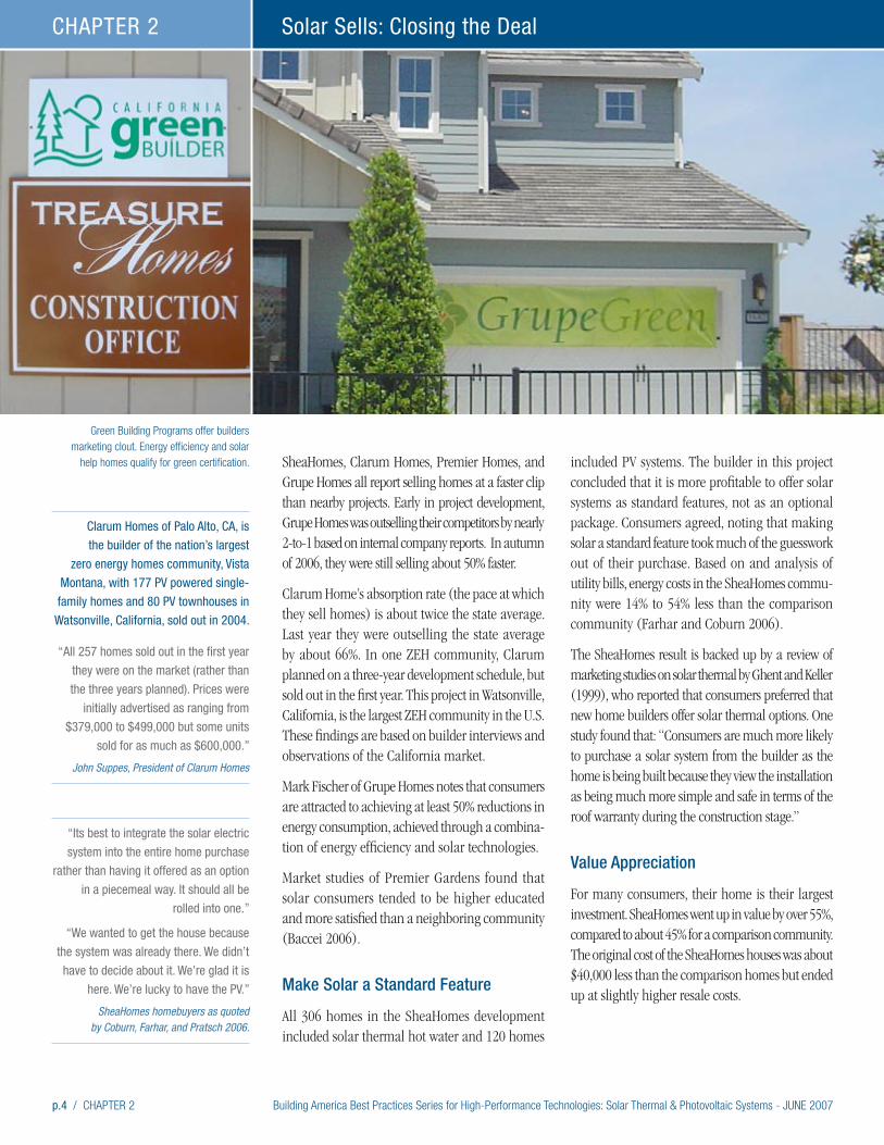
Green Building Programs offer builders marketing clout. Energy efficiency and solar
help homes qualify for green certification.
“Its best to integrate the solar electric
system into the entire home purchase
rather than having it offered as an option
in a piecemeal way. It should all be
rolled into one.”
“We wanted to get the house because
the system was already there. We didn’t
have to decide about it. We’re glad it is
here. We’re lucky to have the PV.” SheaHomes homebuyers as quoted
by Coburn, Farhar, and Pratsch 2006.
Building America Best Practices Series for High-Performance Technologies: Solar Thermal & Photovoltaic Systems - JUNE 2007 CHAPTER 2 / p.5
Solar Sells: Closing the Deal CHAPTER 2
Production Builder Cost Advantage
Production builder advantages show up in solar equipment costs. Studies of California’s PV incentive programs show that systems installed in large new home developments are, on average, far more economical than retrofitted systems, saving 13% to 21% over retrofit systems (Wiser, Bolinger, Cappers and Margolis 2006). Researchers suggest that production builders may drive down solar thermal costs by up to 40%. For consumers who know they want solar technologies, these savings are important. Costs to consumers are even lower thanks to their ability to roll ZEH costs into their primary mortgage.
Selling Value
Builders are interested in providing value to clients. But consumers may have a different view of how solar fits into the equation.
For consumers, part of the value equation relates to the cost of energy. With ZEH, part of the homes costs amount to a locked in price for power over the life of the solar equipment. In an era of large jumps in power and fuel costs, ZEH help to manage risks and reduce future price shocks. Not a bad benefit when some utilities seek out 89% increases in electric rates (See the Baltimore Sun headline listed on page 3).
Consumers are Willing to Pay
Most market research into solar technologies show that financial benefits are important to consumers. Research also shows that consumers are interested in a positive cash flow. By combining solar with energy efficiency improvements, the total package results in a positive cash flow in combination with utility bills and mortgage payments. PV does not achieve positive cash flow by itself, but it does help sell homes with high levels of energy efficiency. Both detailed studies of the SheaHomes community (Coburn, Farhar, and Pratsch 2006) and a national survey (NAHBRC 2006) found similar results.
Getting Green
Builders who choose to advertise their “green” designs have found that buyers are willing to pay for environmental features. Local, regional, and national programs offer methodologies and certification processes for green construction. The certification programs award points based on green features incorporated into home and site designs. Depending on the exact measures implemented, there are a range of certification levels that can be reached. Using suggested Building America energy-efficiency practices, a new home can earn a green certification within a number of different programs. Adding solar technologies to make a ZEH pushes the point totals even higher. For example, a ZEH following Building America recommenda-tions could qualify for the LEED silver rating, or, in parts of California, the Alameda County Green Building Guidelines. By adding other measures, the highest levels of certification are within reach. Green building programs may have requirements in addition to meeting point totals.
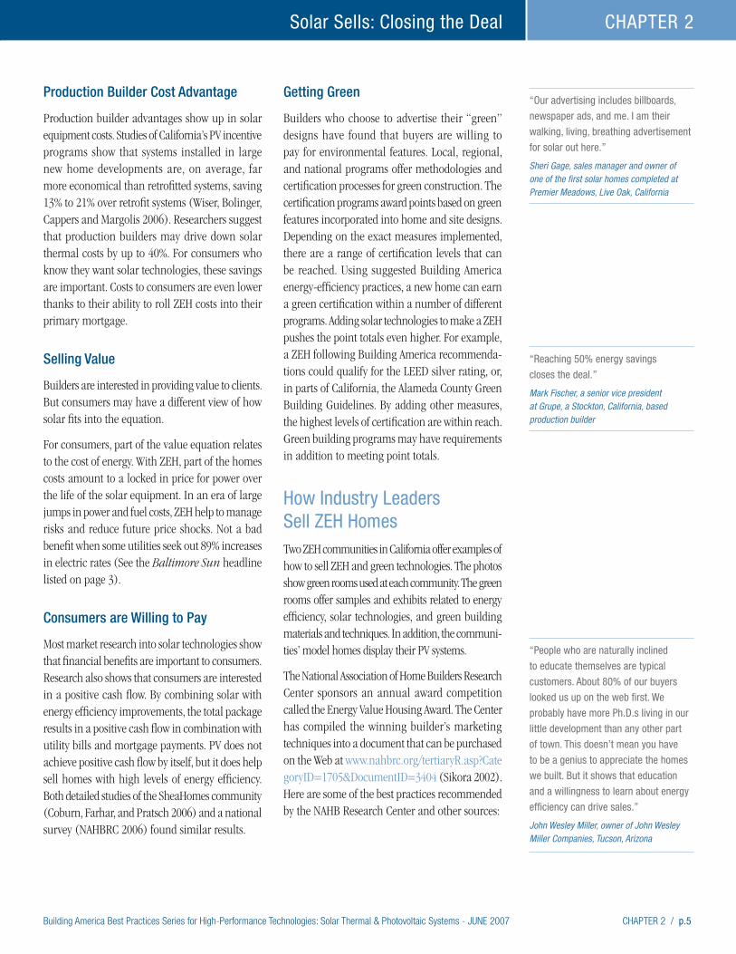
How Industry Leaders Sell ZEH HomesTwo ZEH communities in California offer examples of how to sell ZEH and green technologies. The photos show green rooms used at each community. The green rooms offer samples and exhibits related to energy efficiency, solar technologies, and green building materials and techniques. In addition, the communi-ties’ model homes display their PV systems.
The National Association of Home Builders Research Center sponsors an annual award competition called the Energy Value Housing Award. The Center has compiled the winning builder’s marketing techniques into a document that can be purchased on the Web at www.nahbrc.org/tertiaryR.asp?CategoryID=1705&DocumentID=3404 (Sikora 2002). Here are some of the best practices recommended by the NAHB Research Center and other sources:
“Reaching 50% energy savings
closes the deal.” Mark Fischer, a senior vice president at Grupe, a Stockton, California, based production builder
“Our advertising includes billboards,
newspaper ads, and me. I am their
walking, living, breathing advertisement
for solar out here.” Sheri Gage, sales manager and owner of one of the first solar homes completed at Premier Meadows, Live Oak, California
“People who are naturally inclined
to educate themselves are typical
customers. About 80% of our buyers
looked us up on the web first. We
probably have more Ph.D.s living in our
little development than any other part
of town. This doesn’t mean you have
to be a genius to appreciate the homes
we built. But it shows that education
and a willingness to learn about energy
efficiency can drive sales.” John Wesley Miller, owner of John Wesley Miller Companies, Tucson, Arizona
p.6 / CHAPTER 2 Building America Best Practices Series for High-Performance Technologies: Solar Thermal & Photovoltaic Systems - JUNE 2007
Solar Sells: Closing the Deal CHAPTER 2
• Educate customers and sales professionals. Show buyers how living in an energy-efficient home will benefit them with lower household costs. Vital to customer education is an informed sales staff and team of local sales professionals.
• Walk-throughs and model homes can be invalu-able educational tools for both buyers and sales staff. Model homes with display cutaways of energy features such as insulated attics and wall sections help explain the energy-efficient construction process. Labels, flags, and banners create a fun, self-explanatory message to give buyers a focus while they drive or walk the development. Recent research suggests just how important model homes, models of house features, and other educational tools are to shoppers (Farnsworth 2003).
• Training sessions are effective for educating sales staff and professionals. Slides, sample products, and energy bills work as aids. One builder in Maryland built a prototype ZEH. The builder offered onsite workshops for other area builders and held open houses for consumers. All of these activities were covered by local and national press. The Bob Ward Maximum Efficiency Greenland Model is described in a case study in this document.
• One way to educate consumers is to emphasize an energy-efficiency or ZEH upgrade when signing the final papers. One builder has a wall of testimonials, photos, and utility billing history in his waiting room. All prospects are given an opportunity to view this “wall of fame” before the final sale is made. Another builder has the buyer meet with the building site supervisor after the sale is made. This person gives them one more chance to sign up noting, from a builders’ perspective, what a better house they will get (Rashkin 2002).
• Publications are an educational tool that customers and sales professionals can take home. Develop your own brochures or books or give away reprints of magazine articles, ENERGY STAR brochures, or Building America brochures. Vendors and trade associations can provide excellent materials, often at no charge. For example, excellent information on window performance is available at the Efficient Windows Collaborative Web site at www.efficientwindows.org/index.cfm. Give potential buyers a checklist so they can compare the energy saving measures in your homes with those of other builders.
• Advertising can be used to explain the energy-efficiency advantages and distinguish builders from their competition. The ENERGY STAR Web
“We thought about offering solar as an
option, but I like the way it makes us
unique. When you make it standard,
buyers accept it without hesitation.
Once you decide to do a whole
development with solar, it’s easy to
work it into your schedule and to train
your subcontractors. And we decided it
was the right thing to do.” Mark Fischer, a senior vice president at Grupe,
a Stockton, California, production builder
Information centers make energy features tangible. The more builders tell consumers
about ZEH features, the more consumers want them.
STANDARD HOME ZERO ENERGY HOME
$3,160 $3,240
$173
TOTAL MONTHLY = $3,333TOTAL MONTHLY = $3,320
< MORTGAGE BILLS >
< E< $5 ENERGY EFFICIENCY< $25 SOLAR HOT WATER< $50 SOLAR PV 2.4 kW
NERGY BILLS > $80
Consumer monthly costs for Zero Energy Homes need be no more than typical homes.
Energy savings and incentives can offset added upfront costs, as shown in this example.
A full-size version of this figure is located on page 7 of Chapter 1.
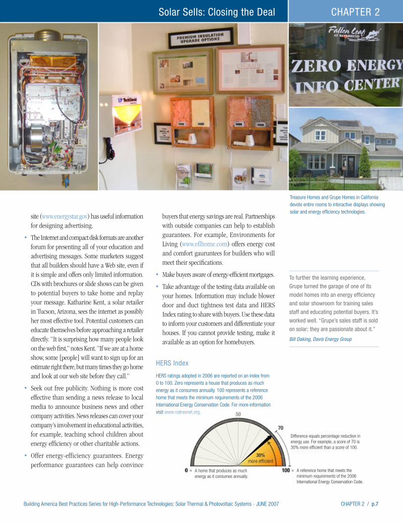
Building America Best Practices Series for High-Performance Technologies: Solar Thermal & Photovoltaic Systems - JUNE 2007 CHAPTER 2 / p.7
Solar Sells: Closing the Deal CHAPTER 2
site (www.energystar.gov) has useful information for designing advertising.
• The Internet and compact disk formats are another forum for presenting all of your education and advertising messages. Some marketers suggest that all builders should have a Web site, even if it is simple and offers only limited information. CDs with brochures or slide shows can be given to potential buyers to take home and replay your message. Katharine Kent, a solar retailer in Tucson, Arizona, sees the internet as possibly her most effective tool. Potential customers can educate themselves before approaching a retailer directly. “It is surprising how many people look on the web first,” notes Kent. “If we are at a home show, some [people] will want to sign up for an estimate right there, but many times they go home and look at our web site before they call.”
• Seek out free publicity. Nothing is more cost effective than sending a news release to local media to announce business news and other company activities. News releases can cover your company’s involvement in educational activities, for example, teaching school children about energy efficiency or other charitable actions.
• Offer energy-efficiency guarantees. Energy performance guarantees can help convince
buyers that energy savings are real. Partnerships with outside companies can help to establish guarantees. For example, Environments for Living (www.eflhome.com) offers energy cost and comfort gauruntees for builders who will meet their specifications.
• Make buyers aware of energy-efficient mortgages.
• Take advantage of the testing data available on your homes. Information may include blower door and duct tightness test data and HERS Index rating to share with buyers. Use these data to inform your customers and differentiate your houses. If you cannot provide testing, make it available as an option for homebuyers.
Treasure Homes and Grupe Homes in California devote entire rooms to interactive displays showing solar and energy efficiency technologies.
To further the learning experience,
Grupe turned the garage of one of its
model homes into an energy efficiency
and solar showroom for training sales
staff and educating potential buyers. It’s
worked well. “Grupe’s sales staff is sold
on solar; they are passionate about it.” Bill Daking, Davis Energy Group
HERS Index
HERS ratings adopted in 2006 are reported on an index from 0 to 100. Zero represents a house that produces as much energy as it consumes annually. 100 represents a reference home that meets the minimum requirements of the 2006 International Energy Conservation Code. For more information visit www.natresnet.org.
Difference equals percentage reduction in energy use. For example, a score of 70 is 30% more efficient than a score of 100.
A reference home that meets the minimum requirements of the 2006 International Energy Conservation Code.
A home that produces as much energy as it consumes annually.
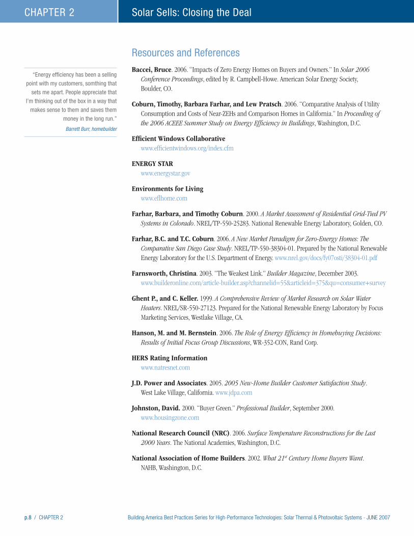
p.8 / CHAPTER 2 Building America Best Practices Series for High-Performance Technologies: Solar Thermal & Photovoltaic Systems - JUNE 2007
Solar Sells: Closing the Deal CHAPTER 2
Resources and References
Baccei, Bruce. 2006. “Impacts of Zero Energy Homes on Buyers and Owners.” In Solar 2006 Conference Proceedings, edited by R. Campbell-Howe. American Solar Energy Society, Boulder, CO.
Coburn, Timothy, Barbara Farhar, and Lew Pratsch. 2006. “Comparative Analysis of Utility Consumption and Costs of Near-ZEHs and Comparison Homes in California.” In Proceeding of the 2006 ACEEE Summer Study on Energy Efficiency in Buildings, Washington, D.C.
Efficient Windows Collaborative www.efficientwindows.org/index.cfm
ENERGY STAR www.energystar.gov
Environments for Living www.eflhome.com
Farhar, Barbara, and Timothy Coburn. 2000. A Market Assessment of Residential Grid-Tied PV Systems in Colorado. NREL/TP-550-25283. National Renewable Energy Laboratory, Golden, CO.
Farhar, B.C. and T.C. Coburn. 2006. A New Market Paradigm for Zero-Energy Homes: The Comparative San Diego Case Study. NREL/TP-550-38304-01. Prepared by the National Renewable Energy Laboratory for the U.S. Department of Energy. www.nrel.gov/docs/fy07osti/38304-01.pdf
Farnsworth, Christina. 2003. “The Weakest Link.” Builder Magazine, December 2003. www.builderonline.com/article-builder.asp?channelid=55&articleid=375&qu=consumer+survey
Ghent P., and C. Keller. 1999. A Comprehensive Review of Market Research on Solar Water Heaters. NREL/SR-550-27123. Prepared for the National Renewable Energy Laboratory by Focus Marketing Services, Westlake Village, CA.
Hanson, M. and M. Bernstein. 2006. The Role of Energy Efficiency in Homebuying Decisions: Results of Initial Focus Group Discussions, WR-352-CON, Rand Corp.
HERS Rating Information www.natresnet.com
J.D. Power and Associates. 2005. 2005 New-Home Builder Customer Satisfaction Study. West Lake Village, California. www.jdpa.com
Johnston, David. 2000. “Buyer Green.” Professional Builder, September 2000. www.housingzone.com
National Research Council (NRC). 2006. Surface Temperature Reconstructions for the Last 2000 Years. The National Academies, Washington, D.C.
National Association of Home Builders. 2002. What 21st Century Home Buyers Want. NAHB, Washington, D.C.
“Energy efficiency has been a selling
point with my customers, somthing that
sets me apart. People appreciate that
I’m thinking out of the box in a way that
makes sense to them and saves them
money in the long run.” Barrett Burr, homebuilder

Building America Best Practices Series for High-Performance Technologies: Solar Thermal & Photovoltaic Systems - JUNE 2007 CHAPTER 2 / p.9
Solar Sells: Closing the Deal CHAPTER 2
National Association of Home Builders Research Center (NAHBRC). 2006. The Potential Impacts of Zero Energy Homes. Prepared for the National Renewable Energy Laboratory, Golden, CO.
NAHBRC – Energy Value Housing Award www.nahbrc.org/tertiaryR.asp?CategoryID=1705&DocumentID=3404
Professional Builder. 2003. “Customer Service Standard Setters.” September 2003. www.housingzone.com
Rashkin, Sam. 2002. “Surprise! Energy Efficiency Sells without Rebates: Results of Mainstream Builders Selling ENERGY STAR Labeled Homes.” In Proceedings of the 2002 ACEEE Summer Study on Energy Efficiency in Buildings, Washington D.C.
Sikora, Jeannie. 2002. Energy Value Housing Award Guide: How to Build and Profit with Energy Efficiency in New Home Construction. National Association of Home Builders Research Center, Upper Marlboro, MD.
Symmetrics Marketing Corporation (SMC). 1999. New Home Buyer Solar Water Heater Trade-Off Study. Prepared for the National Renewable Energy laboratory by Symmetrics Marketing Corporation, Mesa, AZ.
Wiser, Ryan, Mark Bolinger, Peter Cappers, and Robert Margolis. 2006. Letting the Sun Shine on Solar Costs: An Empirical Investigation of Photovoltaic Cost Trends in California. LBNL-59282, NREL/TP-620-39300. Prepared for the U.S. DOE by Lawrence Berkeley National Laboratory, Berkeley, CA, and the National Renewable Energy Laboratory, Golden, CO. http://eetd.lbl.gov/EA/EMP.
Solarvoltaics alone will never get a
home to zero energy bills. A super-
efficient building envelope and
high-performance appliance are key to
cutting energy costs.
“I’ve been in since December 2005, and
my electric bills have ranged from a
high of $70 to a low of $1.60 per month
(for a 1,990 sq ft home). People have
been walking into my sales office who
are paying between $250 and $800 a
month on their electric bills.” Sheri Gage, Sales Manager and owner of one the first solar homes completed at Premier Meadows, a near-ZEH Premier Homes development north of Sacramento, CA

Building America Best Practices Series for High-Performance Technologies: Solar Thermal & Photovoltaic Systems - JUNE 2007 CHAPTER 3 / p.1
High-Performance Home Technologies: Solar Thermal & Photovoltaic Systems
Chapter 3. Solar-Thermal Water Heating
Building America Best Practices Series
Anyone who has touched their steering wheel on a sunny day and burned their fingers, has experienced first hand the physics that work within solar collectors. Solar thermal systems collect heat from the sun for use in space or water heating. For production builders, systems for water heating are mature technologies that can easily be incorporated into new home construction. Solar heated water may be used for space conditioning, pool heating, or domestic consumption. These best practices focus on domestic hot water use. Space conditioning with solar heated water or air is emerging as an efficient technology, but is not yet mature for production building. Pool heating is simple and cost effective, but applies only where pools are built with new houses.
This chapter is divided into three parts. The first summarizes the pieces that go into solar thermal systems. The second describes how the pieces are fitted into systems. And the third summarizes best practices for solar installers and builders.
Photo courtesy of Bill Guiney of Solargenix
Builders’ Brief
• Solar thermal installers can be certified by NABCEP; find out if they are or what their plans are
for becoming certified.
• Only install systems that have been SRCC certified – some states, such as Florida, require their own certification.
• Incorporate solar information into the homeowners manuals and materials that you provide.
• Select packaged systems where possible for the benefits of pre-engineering.
• Choose the simplest systems that will work in your climate.
• In warm climates, with virtually no freezing, Integrated Collector Storage (ICS) systems provide an
inexpensive and straightforward option.
• Some builders have incorporated solar water heating systems into tile roofs.
• With freeze protection, reliable solar water heating is available anywhere in the country.
• Provide space in home designs for pipe runs from solar collectors to storage tanks.
• Insist that solar installers meet with other trades to work out equipment compatibility, supply,
and installation issues.
• Experience has shown that when inspections are done, failure rates on solar thermal systems are very low.
Installers’ Brief
• Use specialized knowledge to educate
builders and other trades. New
construction provides an opportunity
to optimize the equipment and
installation process.
• Take advantage of the bulk purchase
opportunities afforded by production
building.
• Work with site supervisors, roofers,
plumbers, and others to determine
the best installation sequence and
schedule what materials to provide and
to avoid shading from vents and other
roof penetrations.
• Confirm solar exposure before
mounting hardware on the roof.
• Provide quality assurance inspections.
• Many problems are related to
craftsmanship – use quality assurance
techniques to avoid problems.
• Work with the builder to develop
inspection protocols.
• Correct installation and craftsmanship
problems immediately.
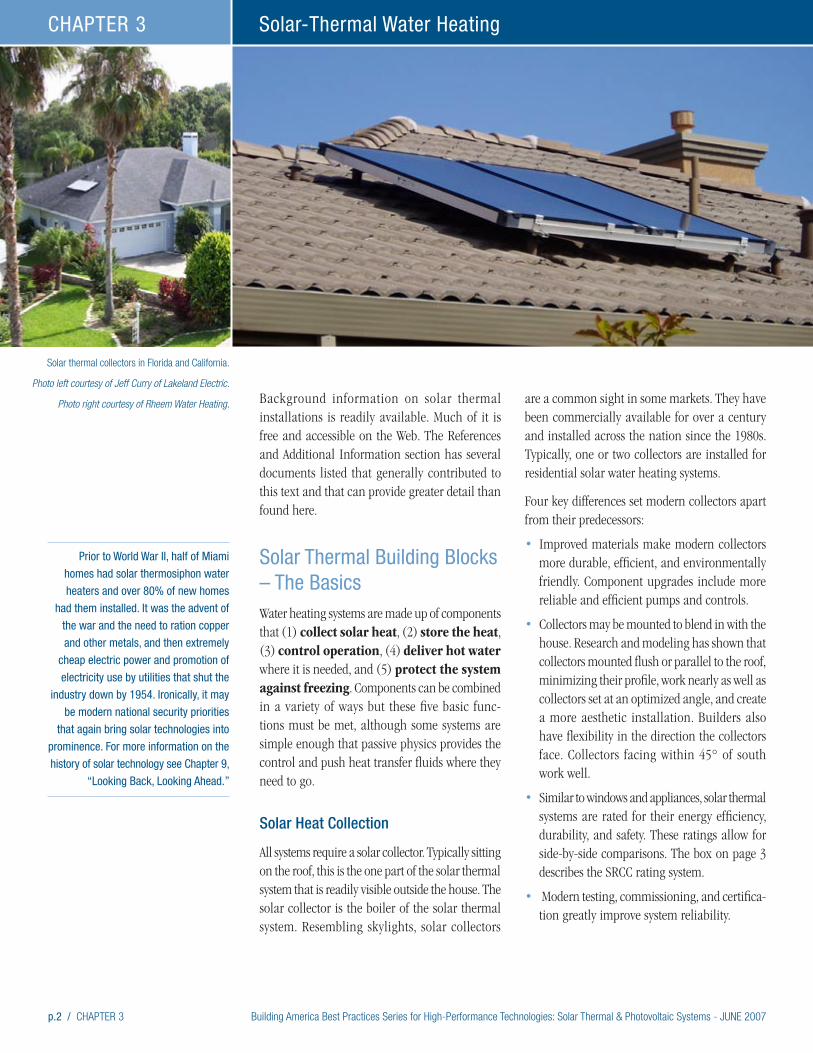
p.2 / CHAPTER 3 Building America Best Practices Series for High-Performance Technologies: Solar Thermal & Photovoltaic Systems - JUNE 2007
Solar-Thermal Water HeatingCHAPTER 3
Background information on solar thermal installations is readily available. Much of it is free and accessible on the Web. The References and Additional Information section has several documents listed that generally contributed to this text and that can provide greater detail than found here.
Solar Thermal Building Blocks – The BasicsWater heating systems are made up of components that (1) collect solar heat, (2) store the heat, (3) control operation, (4) deliver hot water where it is needed, and (5) protect the system against freezing. Components can be combined in a variety of ways but these five basic func-tions must be met, although some systems are simple enough that passive physics provides the control and push heat transfer fluids where they need to go.
Solar Heat Collection
All systems require a solar collector. Typically sitting on the roof, this is the one part of the solar thermal system that is readily visible outside the house. The solar collector is the boiler of the solar thermal system. Resembling skylights, solar collectors
are a common sight in some markets. They have been commercially available for over a century and installed across the nation since the 1980s. Typically, one or two collectors are installed for residential solar water heating systems.
Four key differences set modern collectors apart from their predecessors:
• Improved materials make modern collectors more durable, efficient, and environmentally friendly. Component upgrades include more reliable and efficient pumps and controls.
• Collectors may be mounted to blend in with the house. Research and modeling has shown that collectors mounted flush or parallel to the roof, minimizing their profile, work nearly as well as collectors set at an optimized angle, and create a more aesthetic installation. Builders also have flexibility in the direction the collectors face. Collectors facing within 45° of south work well.
• Similar to windows and appliances, solar thermal systems are rated for their energy efficiency, durability, and safety. These ratings allow for side-by-side comparisons. The box on page 3 describes the SRCC rating system.
• Modern testing, commissioning, and certifica-tion greatly improve system reliability.
Prior to World War II, half of Miami
homes had solar thermosiphon water
heaters and over 80% of new homes
had them installed. It was the advent of
the war and the need to ration copper
and other metals, and then extremely
cheap electric power and promotion of
electricity use by utilities that shut the
industry down by 1954. Ironically, it may
be modern national security priorities
that again bring solar technologies into
prominence. For more information on the
history of solar technology see Chapter 9,
“Looking Back, Looking Ahead.”
Solar thermal collectors in Florida and California.
Photo left courtesy of Jeff Curry of Lakeland Electric.
Photo right courtesy of Rheem Water Heating.
Building America Best Practices Series for High-Performance Technologies: Solar Thermal & Photovoltaic Systems - JUNE 2007 CHAPTER 3 / p.3
Solar-Thermal Water Heating CHAPTER 3
Objective Testing and Rating
The Solar Rating and Certification Corporation (SRCC) rates and certifies solar collectors and overall systems. In 1980, SRCC established its certification and rating program for solar collectors (referred to as OG-100). The program evaluates the maintainability of solar collectors and a thermal performance rating of all-day energy output under prescribed conditions. SRCC programs are in place for solar water heating and swimming pool collectors and water heating systems. Systems are generally for residential solar water heating. Program participation is voluntary and currently 45 manufacturers participate. SRCC ratings are especially important now as solar components from China and Europe are entering the U.S. market.
Testing is directed to durability and performance with test procedures specified by the International Standards Organization (ISO) for water heating collectors and the American Society of Heating, Refrigerating, and Air Conditioning Engineers (ASHRAE – see the References and Resources section at the end of this chapter) for space heating collectors. Manufacturers have the option of using ISO or SRCC durability (quality) standards.
The purpose of the rating is to show how two or more collectors perform under test conditions. The SRCC label states the number of Btus that a collector will produce over a day under the test conditions. This approach makes for easy comparisons across collectors. The collectors are rated for a variety of weather conditions and dimensions and capacities are listed.
The SRCC also certifies solar water heating systems (OG-300). This certification integrates results of collector tests and passive system tests with evaluations against minimum standards of system durability, reliability, safety and operation; as well as factors affecting total system design, installation, maintenance, and service. The complete system of collectors, tanks, pumps, motors, valves, piping, and even the operating and installation manuals are evaluated.
The SRCC uses the Solar Energy Factor (SEF) as its performance rating for solar domestic water heating systems. The SEF is defined as the energy delivered by the system divided by the electrical or gas energy put into the system. The SEF is similar to the Energy Factor given to conventional water heaters by the U.S. Department of Energy and published by the Gas Appliance Manufacturers Association.
In addition, and quite useful to those wishing to determine the savings of a solar water heating system, SRCC also publishes annual performance ratings for certified solar systems. These ratings include kWh and therm savings for the certified systems. Comparisons of certified system performance (based on modeling) are available for representative cities within many states.
Note that Florida has its own certification requirement and the Florida Solar Energy Center has ratings, manuals, and other useful information.
Other resources available on the SRCC website include the following:
• Training videos for solar thermal system installation and inspection
• SRCC installation guides
• Listings of SRCC-rated solar collectors and systems
All resources are available at www.solar-rating.org.
The SRCC provides rating and performance information.
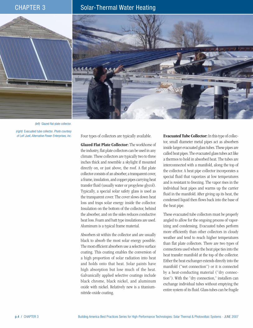
p.4 / CHAPTER 3 Building America Best Practices Series for High-Performance Technologies: Solar Thermal & Photovoltaic Systems - JUNE 2007
Solar-Thermal Water HeatingCHAPTER 3
Four types of collectors are typically available.
Glazed Flat Plate Collector: The workhorse of the industry, flat plate collectors can be used in any climate. These collectors are typically two to three inches thick and resemble a skylight if mounted directly on, or just above, the roof. A flat plate collector consists of an absorber, a transparent cover, a frame, insulation, and copper pipes carrying heat transfer fluid (usually water or propylene glycol). Typically, a special solar safety glass is used as the transparent cover. The cover slows down heat loss and traps solar energy inside the collector. Insulation on the bottom of the collector, behind the absorber, and on the sides reduces conductive heat loss. Foam and batt type insulations are used. Aluminum is a typical frame material.
Absorbers sit within the collector and are usually black to absorb the most solar energy possible. The most efficient absorbers use a selective surface coating. This coating enables the conversion of a high proportion of solar radiation into heat and holds onto that heat. Solar paints have high absorption but lose much of the heat. Galvanically applied selective coatings include black chrome, black nickel, and aluminum oxide with nickel. Relatively new is a titanium- nitride-oxide coating.
Evacuated Tube Collector: In this type of collec-tor, small diameter metal pipes act as absorbers inside larger evacuated glass tubes. These pipes are called heat pipes. The evacuated glass tubes act like a thermos to hold in absorbed heat. The tubes are interconnected with a manifold, along the top of the collector. A heat pipe collector incorporates a special fluid that vaporizes at low temperatures and is resistant to freezing. The vapor rises in the individual heat pipes and warms up the carrier fluid in the manifold. After giving up its heat, the condensed liquid then flows back into the base of the heat pipe.
These evacuated tube collectors must be properly angled to allow for the ongoing process of vapor-izing and condensing. Evacuated tubes perform more efficiently than other collectors in cloudy weather and tend to reach higher temperatures than flat plate collectors. There are two types of connections used where the heat pipe ties into the heat transfer manifold at the top of the collector. Either the heat exchanger extends directly into the manifold (“wet connection”) or it is connected by a heat-conducting material (“dry connec-tion”). With the “dry connection,” installers can exchange individual tubes without emptying the entire system of its fluid. Glass tubes can be fragile
(left) Glazed flat plate collector.
(right) Evacuated tube collector. Photo courtesy of Leif Juell, Alternative Power Enterprises, Inc.
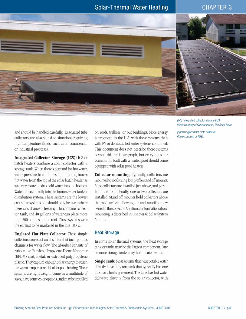
Building America Best Practices Series for High-Performance Technologies: Solar Thermal & Photovoltaic Systems - JUNE 2007 CHAPTER 3 / p.5
Solar-Thermal Water Heating CHAPTER 3
and should be handled carefully. Evacuated tube collectors are also suited to situations requiring high temperature fluids, such as in commercial or industrial processes.
Integrated Collector Storage (ICS): ICS or batch heaters combine a solar collector with a storage tank. When there’s demand for hot water, water pressure from domestic plumbing moves hot water from the top of the solar batch heater as water pressure pushes cold water into the bottom. Water moves directly into the home’s water tank or distribution system. These systems are the lowest cost solar systems but should only be used where there is no chance of freezing. The combined collec-tor, tank, and 40 gallons of water can place more than 500 pounds on the roof. These systems were the earliest to be marketed in the late 1800s.
Unglazed Flat Plate Collector: These simple collectors consist of an absorber that incorporates channels for water flow. The absorber consists of rubber-like Ethylene Propylene Diene Monomer (EPDM) mat, metal, or extruded polypropylene plastic. They capture enough solar energy to reach the warm temperatures ideal for pool heating. These systems are light weight, come in a multitude of sizes, have some color options, and may be installed
on roofs, trellises, or out buildings. More energy is produced in the U.S. with these systems than with PV or domestic hot water systems combined. This document does not describe these systems beyond this brief paragraph, but every house or community built with a heated pool should come equipped with solar pool heaters.
Collector mounting: Typically, collectors are mounted to roofs using low profile stand off mounts. Most collectors are installed just above, and paral-lel to the roof. Usually, one or two collectors are installed. Stand off mounts hold collectors above the roof surface, allowing air and runoff to flow beneath the collector. Additional information about mounting is described in Chapter 6: Solar System Mounts.
Heat Storage
In some solar thermal systems, the heat storage tank or tanks may be the largest component. One or more storage tanks may hold heated water.
Single Tank: Most systems that heat potable water directly have only one tank that typically has one auxiliary heating element. The tank has hot water delivered directly from the solar collector, with
(left) Integrated collector storage (ICS). Photo courtesy of Katharine Kent, The Solar Store
(right) Unglazed flat plate collector. Photo courtesy of NREL
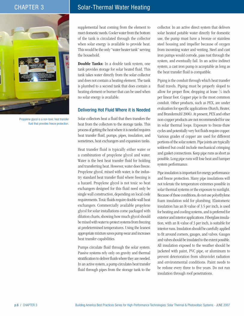
p.6 / CHAPTER 3 Building America Best Practices Series for High-Performance Technologies: Solar Thermal & Photovoltaic Systems - JUNE 2007
Solar-Thermal Water HeatingCHAPTER 3
supplemental heat coming from the element to meet domestic needs. Cooler water from the bottom of the tank is circulated through the collector when solar energy is available to provide heat. This would be the only “water heater tank” serving the household.
Double Tanks: In a double tank system, one tank provides storage for solar heated fluid. This tank takes water directly from the solar collector and does not contain a heating element. The tank is plumbed to a second tank that does contain a heating element or burner that can be used when no solar energy is available.
Delivering Hot Fluid Where it is Needed
Solar collectors heat a fluid that then transfers the heat from the collectors to the storage tanks. This process of getting the heat where it is needed requires heat transfer fluid, pumps, pipes, insulation, and sometimes, heat exchangers and expansion tanks.
Heat transfer fluid is typically either water or a combination of propylene glycol and water. Water is the best heat transfer fluid for holding and transferring heat. However, water does freeze. Propylene glycol, mixed with water, is the indus-try standard heat transfer fluid where freezing is a hazard. Propylene glycol is not toxic so heat exchangers designed for this fluid need only be single wall construction, depending on local code requirements. Toxic fluids require double wall heat exchangers. Commercially available propylene glycol for solar installations come packaged with dilution charts, showing how much glycol should be mixed with water to protect systems from freezing at predetermined temperatures. Using the leanest appropriate mixture saves pump wear and increases heat transfer capabilities.
Pumps circulate fluid through the solar system. Passive systems rely only on gravity and thermal stratification to deliver fluids where they are needed. In an active system, a pump circulates heat transfer fluid through pipes from the storage tank to the
collector. In an active direct system that delivers solar heated potable water directly for domestic use, the pump must have a bronze or stainless steel housing and impeller because of oxygen from incoming water and venting. Steel and cast iron pumps would corrode, pass rust through the system, and eventually fail. In an active indirect system, a cast iron pump is acceptable as long as the heat transfer fluid is compatible.
Piping is the conduit through which heat transfer fluid travels. Piping must be properly sloped to allow for proper flow, dropping at lease 1/4 inch per linear foot. Copper pipe is the most common conduit. Other products, such as PEX, are under evaluation for specific applications (Burch, Heater, and Brandemuhl 2006). At present, PEX and other non-copper products are not recommended for use in solar thermal loops. Exposure to freeze-thaw cycles and potentially very hot fluids require copper. Various grades of copper are used for different portions of the solar system. Pipe joints are typically soldered but could include mechanical crimping and gasket connections. Keep pipe runs as short as possible. Long pipe runs will lose heat and hamper system performance.
Pipe insulation is important for energy performance and freeze protection. Many pipe insulations will not tolerate the temperature extremes possible in solar thermal systems or the exposure to sunlight. Because of these conditions, do not use polyethylene foam insulation sold for plumbing. Elastomeric insulation has an R-value of 3.5 per inch, is used for heating and cooling systems, and is preferred for exterior and interior applications. Fiberglass insula-tion, with an R-value of 3 per inch, is suitable for interior runs. Insulation should be carefully applied to fit around corners, gauges, and valves. Gauges and valves should be insulated to the extent possible. All insulation exposed to the weather should be jacketed with paint, PVC pipe, or aluminum to prevent deterioration from ultraviolet radiation and environmental conditions. Paint needs to be redone every three to five years. Do not run insulation through roof penetrations.
Propylene glycol is a non-toxic heat transfer fluid that provides freeze protection.

Building America Best Practices Series for High-Performance Technologies: Solar Thermal & Photovoltaic Systems - JUNE 2007 CHAPTER 3 / p.7
Solar-Thermal Water Heating CHAPTER 3
The Tucson-Pima County Sustainable Energy Standard specifies that for passive collectors no more than 20 linear feet of pipe should separate integrated collector storage type collectors and storage tanks (www.tucsonmec.org/ses.htm).
Heat exchangers are always needed in propylene glycol systems but sometimes systems using water also use heat exchangers. Heat exchangers allow for heat to be transferred from the solar fluid to either the domestic hot water system, or a space heating system. Systems with heat exchangers are called “indirect” systems, because the fluid from the solar side is not intended to mix with domestic water. Two common designs in heat exchangers for hot water systems are coil-in-tank and wrap-around systems. Heat exchangers reduce system efficiency by 10% to 20%. Some heat exchangers are incorporated into smaller tanks that tie into the domestic hot water tank. In these systems the smaller tank can be stacked on the main tank, saving floor space.
Most indirect systems using a heat transfer fluid other than water have an expansion tank. These tanks allow for changes in fluid volume as tempera-ture changes.
Controllers, Valves, and Gauges
Controllers determine when sufficient solar energy is available and directs the system accordingly. The main controllers function by controlling the pumps that push fluid through the system. Other controls work within the system as safeguards.
Differential Controller: This device is the most common controller and works with two sensors – one at or near the hottest point in the collector and another near the bottom of the storage tank. When the collector sensor finds that temperatures are 8°F to 4°F greater than the tank sensor, the controller starts the pump. These differential temperatures are pre-set by the installer in accordance with the specific characteristics of the installation. When temperature differences are less, typically 4°F, the controller stops the pump.
Photovoltaic Control: Another approach uses a photovoltaic module adjacent to and in the plane of the collector to provide DC power to a DC pump. The PV provider powers only when the sun shines. So, the pump only operates when solar energy is available. The critical part of this application is that the module and pump have to be matched properly for optimal operation (start, stop, flow, etc.).
(left) Rough-in plumbing for a solar thermal system. Photo courtesy of Heliodyne.
(right) Insulation ready for installation.
(bottom-right) A pre-packaged Heliodyne system takes up no more space than a water heater tank. Photo courtesy of Heliodyne.

p.8 / CHAPTER 3 Building America Best Practices Series for High-Performance Technologies: Solar Thermal & Photovoltaic Systems - JUNE 2007
Solar-Thermal Water HeatingCHAPTER 3
(left, middle, right) Field-mounted gauges, pumps, and valves and an example of
a prepackaged unit. Timer Controller: These systems are rarely used and none are certified by the SRCC. These systems are not recommended.
Valves serve many safety and control functions.
• Air vents expel and vent air from the system to prevent air locks and are located at the uppermost part of the system.
• Temperature and pressure relief valves release excessive pressure and temperature. Typically, only pressure relief valves are used in the collector loop. Combination pressure and temperature relief valves are required on domestic water heaters.
• Vacuum breakers prevent vacuum locks during drainage.
• Ball and gate valves isolate parts of the system. Ball valves are typically used for the solar loop.
• Drain valves are used to drain the solar system. Drain valves are also found on all water heaters.
• Check valves prevent thermosiphon heat losses and may be mechanical or motorized.
• Antiscald valves ensure that hot water is condi-tioned with cold water before being used for
domestic use. Antiscald valves are more accurate than mixing valves and are a true “safety” valve. Mixing valves are more of an energy savings device than a safety valve.
• Pressure gauges, temperature gauges, and flow meters monitor the system or allow for technicians to diagnose the system and for homeowners to determine that the system is indeed working.
• Freeze prevention valves open in cold weather to allow water to drain out of exposed collectors. Better freeze protection is available for systems in colder climates. These valves should only be used in typically non freezing climates with ICS or simple systems with pumps.
• Some instruments provide information for diagnostics and maintenance.
Pressure gauge: All closed loop systems require a pressure gauge. On direct and indirect loop systems these gauges indicate if a leak has occurred.
Flow Meter: Flow meters allow owners and service people to determine if pumps are operating and at what rate. These meters should be located in the collector feed line, above the pump.

Building America Best Practices Series for High-Performance Technologies: Solar Thermal & Photovoltaic Systems - JUNE 2007 CHAPTER 3 / p.9
Solar-Thermal Water Heating CHAPTER 3
Temperature gauges: Two gauges are usually plumbed, one for the collector feed line and one for the return line to allow for the visual verification of fluid temperatures.
Freeze Protection
Freeze protection prevents damage to system components from ice formation.
Draindown System: These systems are no longer in use and are not recommended. None are certified by the SRCC.
Drainback System: A drainback tank collects fluid that drains from the solar collector each time the pump turns off. The tank should be located in conditioned space and vertically close to collectors to reduce head pressure. The pump is controlled by a differential controller. Drainback systems are described more fully in the Solar Thermal Systems section, later on this page.
Water Flow: Water is circulated through the collector by a pump with a freeze switch. This method requires electric power and is not reliable when the power goes out, which requires manually draining the collector.
Freeze Prevention Valves: Freeze prevention valves open in cold weather to allow water to drain out of exposed collectors. Better freeze protection is available for systems in colder climates (Ramlow and Nusz 2006).
Propylene Glycol: Propylene glycol systems were described earlier in the “Delivering Hot Fluid Where it is Needed” section on page 6. These systems include a mix of nontoxic propylene glycol and water. The nontoxic propylene glycol is an anti-freeze. The ratio of the two fluids varies depending on the level of protection needed. These systems are more complex than other systems but offer a great method for freeze control in colder climates.
Solar Thermal Systems: Putting the Pieces TogetherSolar components may be combined in many ways to achieve efficient water heating. Systems can be quite simple, or very complex depending on the need for freeze protection, and the system design. This section describes common approaches to system design, starting with the simplest approaches. The very first part of the discussion talks about components that are common to all systems. These common components will not be included in the other discussions. Packaged systems hold the potential for labor savings and greater consumer acceptance and are also discussed up front.
Most systems require the following components:
• pressure relieve valves are important safety devices on all systems – some systems use combined safety and temperature relief valves
• piping to move heat transfer fluids from collectors to storage and to carry cold fluids to the collector
• insulation for the piping
• valves to isolate, bypass, and drain the solar system
• air vents to allow air to escape the system
• insulation for storage tanks.
Packaged systems can greatly simplify installation, save space, and make a more pleasing presentation to consumers. By pre-combining many components, packaged systems can also cut down on labor costs. Some systems combine controllers, sensors, pumps, gauges and valves. These systems also include insulated covers preformed to fit the components and pleasantly styled to look more like dashboards than boiler rooms. The covers can be easily removed and reused.
Solar water heating systems are described using four common terms:
Installers prepare to lift a solar panel onto the roof.

p.10 / CHAPTER 3 Building America Best Practices Series for High-Performance Technologies: Solar Thermal & Photovoltaic Systems - JUNE 2007
Solar-Thermal Water HeatingCHAPTER 3
• Active systems use pumps to move fluids through the system.
• Passive systems rely on the buoyancy of warm water and gravity to move fluids through the system without any pumps.
• Direct systems heat water that feeds directly into the domestic hot water system. Direct systems always use potable water as the heat transfer fluid. In areas with dissolved miner-als, carbon dioxide, or other water quality problems, these systems may require water softeners or other treatments.
• Indirect systems have independent piping and use heat exchangers to isolate solar fluids from potable domestic hot water. Systems using propylene glycol must use heat exchangers, however, water may also be used in indirect systems with heat exchangers.
The following system descriptions include example illustrations of system designs. In practice, systems may be configured in many different ways.
(left, right) ICS mounted directly on roof deck and integrated with mission and cement tile systems.
The photos were taken at a development in Thousand Oaks, California, in 2002. Photos
courtesy of John Harrison of the SRCC and FSEC.
Probability of at Least One Pipe Freeze in 20 Years
Figure courtesy of Jay Burch of NREL.
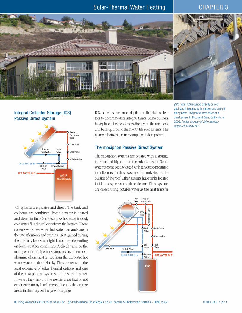
Building America Best Practices Series for High-Performance Technologies: Solar Thermal & Photovoltaic Systems - JUNE 2007 CHAPTER 3 / p.11
Solar-Thermal Water Heating CHAPTER 3
(left, right) ICS mounted directly on roof deck and integrated with mission and cement tile systems. The photos were taken at a development in Thousand Oaks, California, in 2002. Photos courtesy of John Harrison of the SRCC and FSEC.
Integral Collector Storage (ICS) Passive Direct System
ICS systems are passive and direct. The tank and collector are combined. Potable water is heated and stored in the ICS collector. As hot water is used, cold water fills the collector from the bottom. These systems work best when hot water demands are in the late afternoon and evening. Heat gained during the day may be lost at night if not used depending on local weather conditions. A check valve or the arrangement of pipe runs stops reverse thermosi-phoning where heat is lost from the domestic hot water system to the night sky. These systems are the least expensive of solar thermal options and one of the most popular systems on the world market. However, they may only be used in areas that do not experience many hard freezes, such as the orange areas in the map on the previous page.
ICS collectors have more depth than flat plate collec-tors to accommodate integral tanks. Some builders have placed these collectors directly on the roof deck and built up around them with tile roof systems. The nearby photos offer an example of this approach.
Thermosiphon Passive Direct System
Thermosiphon systems are passive with a storage tank located higher than the solar collector. Some systems come prepackaged with tanks pre-mounted to collectors. In these systems the tank sits on the outside of the roof. Other systems have tanks located inside attic spaces above the collectors. These systems are direct, using potable water as the heat transfer
TANK
Free
ze P
rev.
Valv
e
Drain Valve
By-passValve
DrainValve
Drain Valve Shut-Off Valve
PressureRelief Valve
AirVent
BallValve
BallValve
COLD WATER IN HOT WATER OUT
Check Valve
CheckValve
WATERHEATER TANK
Freeze PreventionValve
Drain Valve
DrainValve
Shut-OffValve
PressureRelief Valve
3-Way Ball ValveCOLD WATER IN
HOT WATER OUT
Check Valve
Isolation Valve

p.12 / CHAPTER 3 Building America Best Practices Series for High-Performance Technologies: Solar Thermal & Photovoltaic Systems - JUNE 2007
Solar-Thermal Water HeatingCHAPTER 3
fluid. Water pipes and tanks containing water must be protected from freezing or located in a conditioned space in climates that freeze.
Thermosiphon Passive Indirect System
These similar to the thermosiphon systems described in the preceding section, however, these systems are equipped with heat exchangers within their tanks and may use propylene glycol or other non-freezing fluids for freeze protection. In warm climates, care must be taken to avoid stagnant conditions that can lead to the glycol overheating. In climates that freeze, the water pipes and tanks containing water must be in a conditioned space.
Draindown Active Direct Systems
These systems are not recommended.
Drainback Active Indirect Systems
Drainback systems use water as the heat transfer fluid. Some manufacturers recommend a mix of water and propylene glycol. All water in the collector and pipe lines drains from the system into a reservoir when the pump shuts off. The system is suited to most climates. These systems work best in warm climates because they also drainback when the system has met a maximum set temperature in the storage tank. This automatic safeguard against overheating avoids problems when hot water demand is very low, such as during
(left) Recent Innovations: Davis Energy Group is working with SunEarth and NREL to develop
polymer-based ICS. Photo courtesy of Jay Burch of NREL.
(right) Photo courtesy of Rheem Water Heating.
TANK
Free
ze P
rev.
Valv
e
Drain Valve
By-passValve
DrainValve
Drain Valve Shut-Off Valve
PressureRelief Valve
AirVent
BallValve
BallValve
COLD WATER IN HOT WATER OUT
Check Valve
CheckValve
Heat Exchanger
P/TReliefValve
Drain Valve
Pressure Relief Valve
Shut-Off Valve
COLD WATER IN HOT WATER OUT
Drain
Wrap Around Heat Exchanger
SightGlass
Pump
Drain
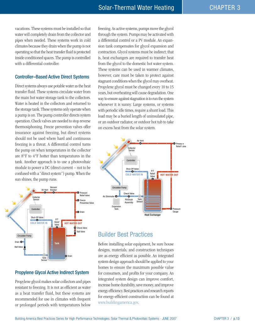
Building America Best Practices Series for High-Performance Technologies: Solar Thermal & Photovoltaic Systems - JUNE 2007 CHAPTER 3 / p.13
Solar-Thermal Water Heating CHAPTER 3
vacations. These systems must be installed so that water will completely drain from the collector and pipes when needed. These systems work in cold climates because they drain when the pump is not operating so that the heat transfer fluid is protected inside conditioned spaces. The pump is controlled with a differential controller.
Controller–Based Active Direct Systems
Direct systems always use potable water as the heat transfer fluid. These systems circulate water from the main hot water storage tank to the collectors. Water is heated in the collectors and returned to the storage tank. These systems only operate when a pump is on. The pump controller directs system operation. Check valves are needed to stop reverse thermosiphoning. Freeze prevention valves offer insurance against freezing, but direct systems should not be used where hard and continuous freezing is a threat. A differential control turns the pump on when temperatures in the collector are 8°F to 4°F hotter than temperatures in the tank. Another approach is to use a photovoltaic module to power a DC (direct current – not to be confused with a “direct system”) pump. When the sun shines, the pump runs.
Propylene Glycol Active Indirect System
Propylene glycol makes solar collectors and pipes resistant to freezing. It is not as efficient as water as a heat transfer fluid, but these systems are recommended for use in climates with frequent or prolonged periods with temperatures below
freezing. As active systems, pumps move the glycol through the system. Pumps may be activated with a differential control or a PV module. An expan-sion tank compensates for glycol expansion and contraction. Glycol systems must be indirect; that is, heat exchangers are required to transfer heat from the glycol to the domestic hot water system. These systems can be used in warmer climates, however, care must be taken to protect against stagnant conditions when the glycol may overheat. Propylene glycol must be changed every 10 to 15 years, but overheating will cause degradation. One way to ensure against stagnation is to run the system whenever it is sunny. Large systems, or systems with periodic idle times, require a shunt load. This load may be a buried length of uninsulated pipe, or an outdoor radiator, or outdoor hot tub to take on excess heat from the solar system.
Builder Best PracticesBefore installing solar equipment, be sure house designs, materials, and construction techniques are as energy efficient as possible. An integrated system design approach should be applied to your homes to ensure the maximum possible value for consumers, and profits for your company. An integrated system design can improve comfort, increase home durability, save money, and improve energy efficiency. Best practices and research reports for energy-efficient construction can be found at www.buildingamerica.gov.
P/TReliefValve
Drain
Shut-Off Valve
Air VentVacuumBreaker
HOT WATER OUT
Drain
Drain
Check Valve
Tank
Controller
Circulator Pump
PressureRelief Valve
FreezePrevention Valve
Ball Valve
Ball Valve
TankSensor
CollectorSensor
COLD WATER IN
P/TReliefValve
Air Eliminator
Shut-Off Valve
Air Vent
Fill/DrainAssembly
Check Valve
HOT WATER OUT
Heat Exchanger
Controller
Circulator Pump
ExpansionTank
PressureRelief Valve
PressureGauge
TankSensor
CollectorSensor
COLD WATER IN

p.14 / CHAPTER 3 Building America Best Practices Series for High-Performance Technologies: Solar Thermal & Photovoltaic Systems - JUNE 2007
Solar-Thermal Water HeatingCHAPTER 3
Inviting solar thermal professionals to join your building team will bring experience and technical capability to help minimize system problems and maximize system performance. Many firms have been in business since the 1970s. Check out how long your potential installers and suppliers have been in business.
Installation companies should be familiar with SRCC collector and solar system ratings. Ask poten-tial installers and suppliers to show you the SRCC labels for the systems they handle. Compare their systems with others in the SRCC directory which lists the performance of every system tested. Only install systems that have been SRCC certified. Note that Florida has its own certification requirement and the Florida Solar Energy Center has ratings, manuals, and other useful information.
SRCC-certified systems require that an owners manual be provided to homeowners. Installers should show you this manual and production builders should incorporate it into the homeowners manuals and materials that you provide.
Solar thermal installers can be certified by NABCEP (North American Board of Certified Energy Practitioners). This process will have its initial test and candidates in autumn 2006. So, for now, certified installers will be hard to find. But, solar energy associations, community colleges, manufacturers, and others offer training. Ask installation companies what types of training their installers receive and if they plan to pursue NABCEP certification. Florida requires that install-ers have a solar contractor’s license.
Solar thermal installers and manufacturers can help with system design. Residential design is straight forward and experienced installers will know local climate constraints and availability issues. Work with installers to select the systems to be used in your houses. Select packaged systems where possible for the benefits of pre-engineering. Installers will know local code restrictions and permitting requirements.
Choose the simplest systems that will work in your climate. The Cold and Very Cold climate covers over half the area of the 48 conterminous states. Freezing
is common in this climate zone and propylene glycol or drainback systems are recommended. Evacuated tube (heat pipe) systems are receiving more attention, but are expensive. Where snow accumulation is common, evacuated tubes are well enough insulated that snow may not melt off of them and may block solar heat gain. In the warmest of areas, where freezing is not an issue, ICS and water based thermosiphon and active systems work great. Everywhere except the warmest of areas, solar thermal systems must be designed to accommodate freezing, but there is flexibility in how this protection is achieved.
Provide space in home designs for pipe runs from solar collectors to storage tanks.Pipe slope can be critical in systems that rely on drainage for freeze protection. In these systems, pipes must drop at least 1/4 inch every linear foot. If pipes cross open areas, ensure that equipment installers will not expect to use those areas for access to HVAC or other equipment. If the pipes cross a path where they will get pushed out of the way, they may be pushed upward, creating a trap for flowing water, and establishing a freeze hazard. Pipe runs should be kept to less than 20 feet if possible.
Ensure there is adequate space in the utility area for solar storage tanks, pumps, valves, and pipes. Note that some packaged systems can sit on top of a single tank, taking up no extra floor space.
Insist that solar installers meet with other trades to work out equipment compatibility, supply, and installations issues. For example:
• Plumbers and solar installers need to be clear on who is providing which storage tanks and auxiliary heating systems, and when.
• Plumbers need to know that continuously operating, whole-house circulating pumps are incompatible with direct solar systems.
• Plumbers and installers need to inform each other about any problems with corrosive local water supplies.
• Roofers need to know what types of flashing to use, who will be installing it, and when.
• Trades requiring roof penetrations need to know what areas are off limits in order to reserve space
“We pride ourselves on repeat business
and good customer service. For us to do
the installation with no experience would
have been a warrantee and customer
relations nightmare…The vendor has
licensed plumbers and electricians
specifically trained in solar installations.
For us, this made the most sense.” Rich Michal, Civano Project Manager
for Pulte Tucson, in Arizona

Building America Best Practices Series for High-Performance Technologies: Solar Thermal & Photovoltaic Systems - JUNE 2007 CHAPTER 3 / p.15
Solar-Thermal Water Heating CHAPTER 3
and sunlight for the solar system.
• PV and solar thermal installers need to know what parts of the roof to use for their systems. Typically the truest southern exposure should go to the PV installation unless a western exposure is needed to reduce utility peak demand.
• For longer-term performance, landscape designers and installers need to keep the southern exposure unobstructed from trees and outbuildings.
After exterior sheathing is installed, solar piping, wiring, and mounts may be installed. Rough-in plumbing for the solar thermal system may be installed at the same time as the domestic water plumbing rough-in. While on the roof before finish roofing has been installed, the solar installer should spray paint on the underside of the roof the boundaries needed for the solar panels and sections of the roof that should be off limits to other penetrations that may cause shading.
Solar collectors that are to be integrated into the roof are installed directly to the deck before finish roofing. The term “integrated” can be confusing here. In this context integrated means to be made a part of the roof. The confusion may come with the name for ICS or integrated collector storage type collectors. In ICS collectors the storage tank is integrated with the collector.
Final solar equipment can be installed after the finished roof is installed and sheetrock has been installed. It may also be advantageous to wait until after interior and exte-rior painting. Waiting avoids problems with overspray on solar collector glazing or PV modules, and avoids blocking difficult to reach places behind storage tanks and equipment.
Production builders should be using a quality assurance process that includes pressurization tests for the house and duct work. Quality assurance should also include the inspection and testing of all solar thermal and PV equipment. Experience has shown that when inspections have been done, failure rates on solar thermal systems are very low, much less than 1%. Train your quality inspection staff or sub contractor, or hire a specialty sub contractor, to test and inspect solar systems. Local utilities may help with this function.
Solar Installer Best PracticesThis document does not provide detailed technical best practices for installers. Other references, listed in the Additional Information section, can help with details. What this section does do is provide insights into working with production builders.
The largest market for solar thermal installers has traditionally been in retrofit situations. In retrofit settings, the installer takes whatever conditions they find and makes things work. Seldom do other trades get involved. In the production building of new residences, the emphasis should be on systems integration, optimal design, and interaction with other trades.
New construction provides an opportunity to optimize the equipment and installation process. Work with manufacturers to package systems that will have consumer appeal. Consumers value floor space over exposed pipes, valves, and gauges. Select packages that preserve floor space and maintain a tidy appearance.
Take advantage of the bulk purchase opportunities afforded by production building. Work with the builder and manufacturer to ensure the lowest prices to production builders. Bear in mind that the builder has essentially taken much of the risk and marketing costs out of the solar systems installed on production homes.
Work with the builder and his or her designers to draw the solar system into the plans. System loca-tion may change with orientation and site access, but putting the system on the plans alerts other subcontractors, site supervisors, and inspectors that the systems are going in. The plans should include predetermined pipe runs between the collectors and the location of storage tanks. If needed, the plans should also indicate any structural additions added for easier or stronger installations.
Production building incorporates factory-like processes in the field. It is not uncommon to have houses in various stages of construction as one looks down a street. Depending on the size of the project, it is possible that every trade that supports a particular builder will be represented
p.16 / CHAPTER 3 Building America Best Practices Series for High-Performance Technologies: Solar Thermal & Photovoltaic Systems - JUNE 2007
Solar-Thermal Water HeatingCHAPTER 3
on the job site every day, but working on different houses. Thermal solar installers will need to fit into this rhythm. It may be necessary to schedule crews to do pre-installations, collector installations, and interior component installations. Different crews may do these tasks simultaneously, or one crew may have different jobs at different times. Be clear with the site supervisor about demands for crew time.
Work with site supervisors, roofers, plumbers, and others to determine the best time to schedule and what materials to provide. Pay attention to other trades that will be working in the same spaces.
• Spray paint or otherwise mark roof areas before finish roofing is installed that need to be protected for mounting collectors and to maintain solar exposure.
• If collectors go in before painting is complete, cover them with plastic to protect against overspray. Wind may carry overspray from nearby houses so check the status of painting on neighboring houses. Remove the plastic when painting is complete or ensure that somebody has that responsibility.
• Protect pipe runs from other trades that may also need access to the same spaces or that may need to create runs of their own.
• Label pipe runs so that they are not pushed up and out of the way, creating water traps and freeze hazards.
• Work with the builder or designer to establish pipe runs in plans to avoid conflicts and main-tain slopes. Also add to the plans any structural changes that are needed for mounting.
• To avoid confusion, keep solar pipe runs away from other plumbing runs to the extent possible, especially in houses using copper pipes (rather than PEX or another product) for potable water system.
• Keep pipe runs away from the perimeter of the building or other locations where nailing or screwing will be occurring. High activity areas include kitchen and bath walls, and above doorways and windows that may be moved. In addition to avoiding damage, an added benefit is that interior locations are less likely to freeze.
Solar installers are a specialized trade within the construction industry and often combine functions of many traditional trades, such as designers, roofers, and plumbers. The design and installation of solar thermal systems requires a wide range of activities that often includes:
• Activities evaluating the building and roof orientation
• Roof work
• Plumbing rough-in, system component integration, and final equipment installation and start-up.
No one traditional trade combines all of these functions without significant training. Solar installers need to educate builders about the trade’s special products and needs that may require added expense.
Solar installers need to confirm solar exposure before mounting hardware on the roof.
Provide quality assurance inspections. Work with the site supervisor. Learn from the inspections to improve future work. Utility and government programs that have involved evaluations have found that most system failures are related to craftsmanship rather than system design or material flaws (for example, FSEC 2006b). These types of problems tend to be related to shading, insulation, and system connections. Three solutions lend themselves to solving these types of problems:
• Train installers in proper methods and materials.
• Select prepackaged systems that minimize onsite connections and insulation.
• Inspect installations and correct problems immediately.
In a study of solar thermal retrofits, FSEC staff discovered many problem areas related to craftsmanship (Harrison and Long 1998). These areas and some design issues are shown in the following table. The photos used in this table are from John Harrison of the SRCC and FSEC and originally appeared in the report indicated above, unless otherwise noted.

Building America Best Practices Series for High-Performance Technologies: Solar Thermal & Photovoltaic Systems - JUNE 2007 CHAPTER 3 / p.17
Solar-Thermal Water Heating CHAPTER 3
THE Wrong WAY THE right WAY
Always confirm that solar exposure is unobstructed. Shading is a critical flaw in installation.
Photo middle courtesy of Michael Baechler, PNNL.Photo far right courtesy of Bill Guimey, Solargenix.
If local water is corrosive to copper, use treatments or indirect systems.
Photo left courtesy of Mahoney and Menicucci 2002. Photo right courtesy of Michael Baechler, PNNL.
Efficient roof placement minimizes pipe runs and keeps pipes sloping downward. Keep pipe runs less than 20 feet if possible.
Bolts used in mounting must be secured and the mount must be sealed.
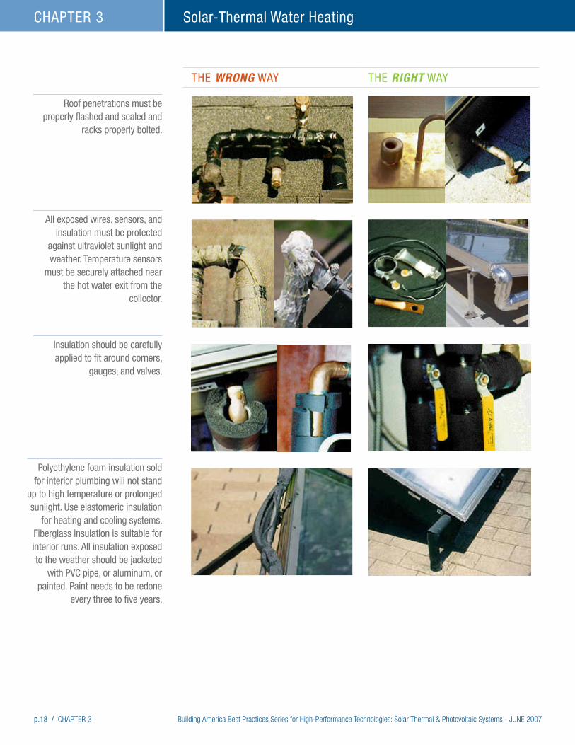
p.18 / CHAPTER 3 Building America Best Practices Series for High-Performance Technologies: Solar Thermal & Photovoltaic Systems - JUNE 2007
Solar-Thermal Water HeatingCHAPTER 3
THE Wrong WAY THE right WAY
Roof penetrations must be properly flashed and sealed and
racks properly bolted.
All exposed wires, sensors, and insulation must be protected
against ultraviolet sunlight and weather. Temperature sensors
must be securely attached near the hot water exit from the
collector.
Polyethylene foam insulation sold for interior plumbing will not stand
up to high temperature or prolonged sunlight. Use elastomeric insulation
for heating and cooling systems. Fiberglass insulation is suitable for interior runs. All insulation exposed to the weather should be jacketed
with PVC pipe, or aluminum, or painted. Paint needs to be redone
every three to five years.
Insulation should be carefully applied to fit around corners,
gauges, and valves.

Building America Best Practices Series for High-Performance Technologies: Solar Thermal & Photovoltaic Systems - JUNE 2007 CHAPTER 3 / p.19
Solar-Thermal Water Heating CHAPTER 3
THE Wrong WAY THE right WAY
Install air vents in a true vertical position.
Attic pipe insulation must be secured. Insulation on right is glued and mitered. Note that insulation abuts roof decking and does not penetrate it. The hole through the deck must be caulked.
Seal and hide penetrations through interior ceilings and walls for fire protection and to block air leaks. In new construction, these types of penetrations should be minimal.

p.20 / CHAPTER 3 Building America Best Practices Series for High-Performance Technologies: Solar Thermal & Photovoltaic Systems - JUNE 2007
Solar-Thermal Water HeatingCHAPTER 3
Resources and References
ASHRAE Standard 93. “Methods of Testing to Determine the Thermal Performance of Solar Collectors,” and ASHRAE Standard 96, “Methods of Testing to Determine the Thermal Performance of Unglazed, Flat Plate, Liquid Solar Collectors.”
Aztec Solar. Undated. Solar Water Heating Systems, Solar Pool Heating Systems. Aztec Solar. www.aztecsolar.com.
Burch, Jay, Morgan Heater, and Mike Brandemuhl. 2006. “Northward Market Extension for Passive Solar Water Heaters By Using Pipe Freeze Protection with Freeze-Tolerant Piping.” Solar 2006 Conference Proceedings, edited by R. Campbell-Howe. American Solar Energy Society, Boulder, CO.
Florida Solar Energy Center (FSEC). 2006a. Solar Water and Pool Heating Manual: Design and Installation & Repair and Maintenance. University of Central Florida, Orlando, FL. www.fsec.ucf.edu/en/industry/resources/solar_thermal/manual/index.htm.
Harrison, J., and S. Long. 1998. Solar Weatherization Assistance Program. FSEC-CR-1028-98, Prepared by the Florida Solar Energy Center for the Florida Department of Community Affairs, Tallahassee, FL, 25 August 1998. www2.fsec.ucf.edu/en/publications/html/FSEC-CR-1028-98/index.htm.
ISO 9806-1:1994. Test methods for solar collectors – Part 1: Thermal performance of glazed liquid heating collectors including pressure drop, ISO 9806-1:1994, International Organization for Standardization, Geneva, Switzerland. www.iso.ch/iso/en/ISOOnline.frontpage.
ISO 9806-2:1995. Test Methods for solar collectors – Part 2: Qualification test procedure, ISO 9806-2:1995, International Organization for Standardization, Geneva, Switzerland. www.iso.ch/iso/en/ISOOnline.frontpage.
ISO 9806-3:1995. Test methods for solar collectors – Part 3: Thermal performance of unglazed liquid heating collectors (sensible heat transfer only) including pressure drop, ISO 9806-3:1995, International Organization for Standardization, Geneva, Switzerland. www.iso.ch/iso/en/ISOOnline.frontpage.
Lane, Tom. 2004. Solar Hot Water Systems: Lessons Learned 1977 to Today. Energy Conservation Services to North Florida, Inc. Gainesville, FL. www.ecs-solar.com.
Mahoney, Rod, and Dave Menicucci. 2002. Copper Corrosion Analysis of Civano Solar Collectors: Final Report. Prepared by Sandia National Laboratory for the U.S. Department of Energy, Washington, D.C.
Patterson, John. 2005. “Solar Hot Water: Simplified.” Home Power Magazine, June and July 2005.
Ramlow, Bob and Benjamin Nusz. 2006. Solar Water Heating. New Society Publishers, Gabriola Island, Canada.
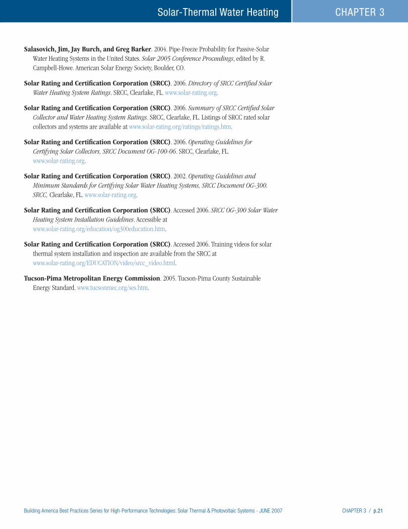
Building America Best Practices Series for High-Performance Technologies: Solar Thermal & Photovoltaic Systems - JUNE 2007 CHAPTER 3 / p.21
Solar-Thermal Water Heating CHAPTER 3
Salasovich, Jim, Jay Burch, and Greg Barker. 2004. Pipe-Freeze Probability for Passive-Solar Water Heating Systems in the United States. Solar 2005 Conference Proceedings, edited by R. Campbell-Howe. American Solar Energy Society, Boulder, CO.
Solar Rating and Certification Corporation (SRCC). 2006. Directory of SRCC Certified Solar Water Heating System Ratings. SRCC, Clearlake, FL. www.solar-rating.org.
Solar Rating and Certification Corporation (SRCC). 2006. Summary of SRCC Certified Solar Collector and Water Heating System Ratings. SRCC, Clearlake, FL. Listings of SRCC rated solar collectors and systems are available at www.solar-rating.org/ratings/ratings.htm.
Solar Rating and Certification Corporation (SRCC). 2006. Operating Guidelines for Certifying Solar Collectors, SRCC Document OG-100-06. SRCC, Clearlake, FL. www.solar-rating.org.
Solar Rating and Certification Corporation (SRCC). 2002. Operating Guidelines and Minimum Standards for Certifying Solar Water Heating Systems, SRCC Document OG-300. SRCC, Clearlake, FL. www.solar-rating.org.
Solar Rating and Certification Corporation (SRCC). Accessed 2006. SRCC OG-300 Solar Water Heating System Installation Guidelines. Accessible at www.solar-rating.org/education/og300education.htm.
Solar Rating and Certification Corporation (SRCC). Accessed 2006. Training videos for solar thermal system installation and inspection are available from the SRCC at www.solar-rating.org/EDUCATION/video/srcc_video.html.
Tucson-Pima Metropolitan Energy Commission. 2005. Tucson-Pima County Sustainable Energy Standard. www.tucsonmec.org/ses.htm.
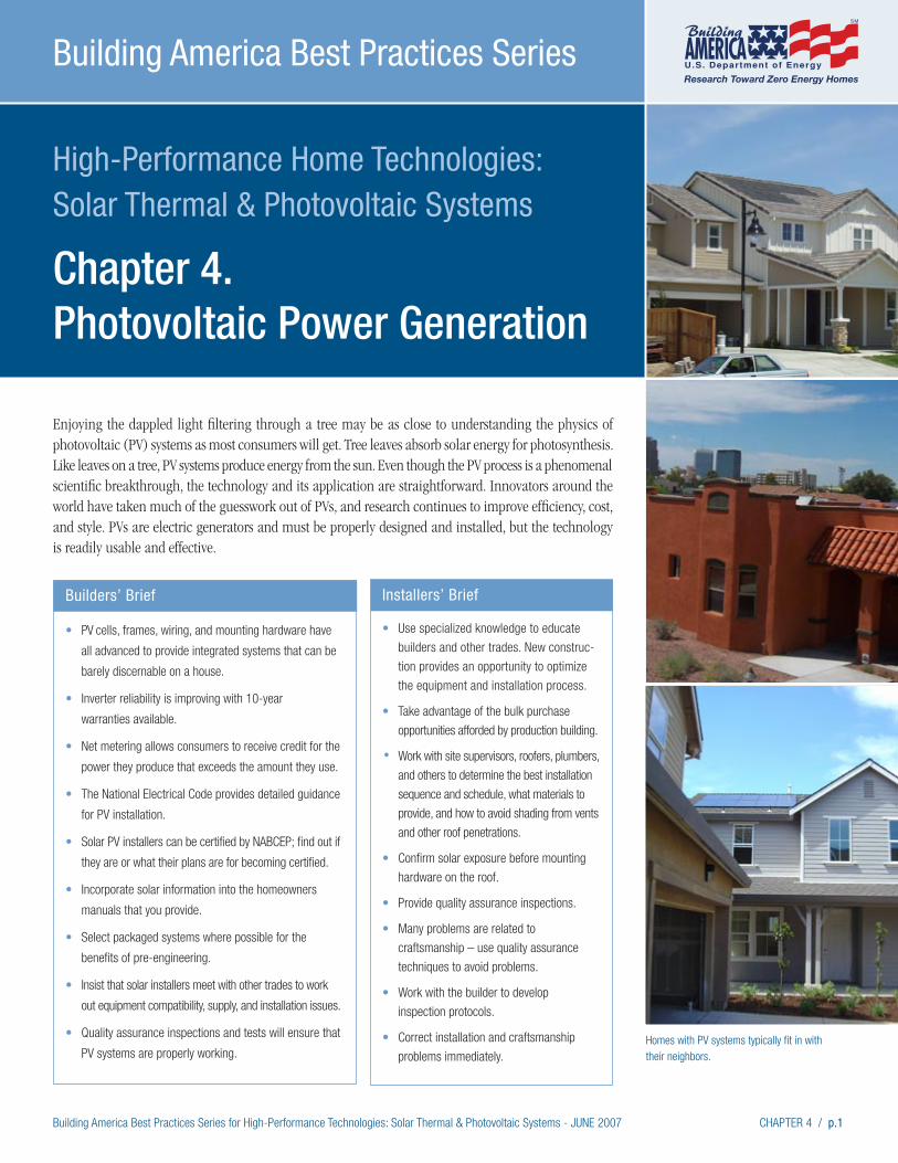
Building America Best Practices Series for High-Performance Technologies: Solar Thermal & Photovoltaic Systems - JUNE 2007 CHAPTER 4 / p.1
High-Performance Home Technologies: Solar Thermal & Photovoltaic Systems
Chapter 4. Photovoltaic Power Generation
Building America Best Practices Series
Homes with PV systems typically fit in with their neighbors.
Enjoying the dappled light filtering through a tree may be as close to understanding the physics of photovoltaic (PV) systems as most consumers will get. Tree leaves absorb solar energy for photosynthesis. Like leaves on a tree, PV systems produce energy from the sun. Even though the PV process is a phenomenal scientific breakthrough, the technology and its application are straightforward. Innovators around the world have taken much of the guesswork out of PVs, and research continues to improve efficiency, cost, and style. PVs are electric generators and must be properly designed and installed, but the technology is readily usable and effective.
Builders’ Brief
• PV cells, frames, wiring, and mounting hardware have
all advanced to provide integrated systems that can be
barely discernable on a house.
• Inverter reliability is improving with 10-year
warranties available.
• Net metering allows consumers to receive credit for the
power they produce that exceeds the amount they use.
• The National Electrical Code provides detailed guidance
for PV installation.
• Solar PV installers can be certified by NABCEP; find out if
they are or what their plans are for becoming certified.
• Incorporate solar information into the homeowners
manuals that you provide.
• Select packaged systems where possible for the
benefits of pre-engineering.
• Insist that solar installers meet with other trades to work
out equipment compatibility, supply, and installation issues.
• Quality assurance inspections and tests will ensure that
PV systems are properly working.
Installers’ Brief
• Use specialized knowledge to educate
builders and other trades. New construc-
tion provides an opportunity to optimize
the equipment and installation process.
• Take advantage of the bulk purchase
opportunities afforded by production building.
• Work with site supervisors, roofers, plumbers,
and others to determine the best installation
sequence and schedule, what materials to
provide, and how to avoid shading from vents
and other roof penetrations.
• Confirm solar exposure before mounting
hardware on the roof.
• Provide quality assurance inspections.
• Many problems are related to
craftsmanship – use quality assurance
techniques to avoid problems.
• Work with the builder to develop
inspection protocols.
• Correct installation and craftsmanship
problems immediately.
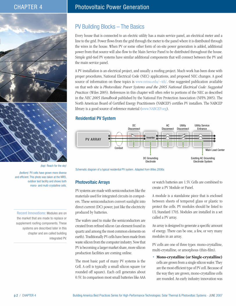
p.2 / CHAPTER 4 Building America Best Practices Series for High-Performance Technologies: Solar Thermal & Photovoltaic Systems - JUNE 2007
Photovoltaic Power GenerationCHAPTER 4
Photovoltaic Arrays
PV systems are made with semiconductors like the materials used for integrated circuits in comput-ers. These semiconductors convert sunlight into direct current (DC) power, just like the electricity produced by batteries.
The wafers used to make the semiconductors are created from refined silicon (an element found in quartz and among the most common elements on earth). Traditionally PV cells have been made from waste silicon from the computer industry. Now that PV is becoming a larger market share, more silicon production facilities are coming online.
The most basic part of many PV systems is the Cell. A cell is typically a small silicon square (or rounded off square). Each cell generates about 0.5V. In comparison most small batteries like AAA
or watch batteries are 1.5V. Cells are combined to create a PV Module or Panel.
A module is a standalone piece that is enclosed between sheets of tempered glass or plastic to protect the cells. PV modules should be listed to UL Standard 1703. Modules are installed in a set called a PV array.
An array is designed to generate a specific amount of energy. There can be one, a few, or very many modules in an array.
PV cells are one of three types: mono-crystalline, multi-crystalline, or amorphous (thin-film).
• Mono-crystalline (or Single-crystalline) cells are grown from a single silicon wafer. They are the most efficient type of PV cell. Because of the way they are grown, mono-crystalline cells are rounded. An early industry innovation was
(top) Reach for the sky!
(bottom) PV cells have grown more diverse and efficient. This photo was taken at the NREL
outdoor test facility and shows both mono- and multi-crystalline cells.
Recent Innovations: Modules are on
the market that are made to replace or
supplement roofing components. These
systems are described later in this
chapter and are called building
integrated PV.
PV Building Blocks – The BasicsEvery house that is connected to an electric utility has a main service panel, an electrical meter and a line to the grid. Power flows from the grid through the meter to the panel where it is distributed through the wires in the house. When PV or some other form of on-site power generation is added, additional power from that source will also flow to the Main Service Panel to be distributed throughout the house. Simple grid-tied PV systems have similar additional components that will connect between the PV and the main service panel.
A PV installation is an electrical project, and usually a roofing project. Much work has been done with proper procedures, National Electrical Code (NEC) applications, and proposed NEC changes. A good source of information on these topics is www.nmsu.edu/~tdi/. One suggested publication available on that web site is Photovoltaic Power Systems and the 2005 National Electrical Code: Suggested Practices (Wiles 2005). References in this chapter will often refer to portions of the NEC as described in the NEC 2005 Handbook published by the National Fire Protection Association (NFPA 2005). The North American Board of Certified Energy Practitioners (NABCEP) certifies PV installers. The NABCEP library is a good source of reference material (www.NABCEP.org).
PV ARRAY
DCDisconnect
Inverter
DC GroundingElectrode
Conduit
Existing AC GroundingElectrode System
ACDisconnect
UtilityDisconnect
Utility ServiceEntrance
Main Load Center
+-
+-
L1
L2
L1
L2
N
Schematic diagram of a typical residential PV system. Adapted from Wiles 2006a.
Residential PV System
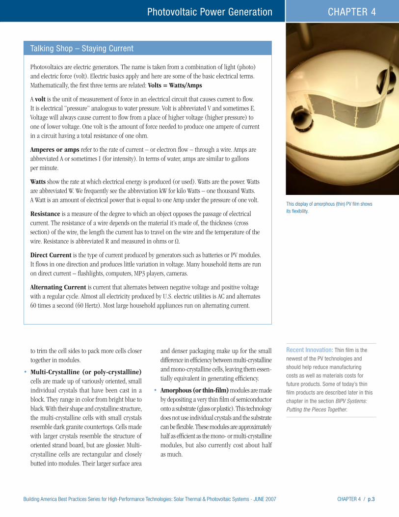
Building America Best Practices Series for High-Performance Technologies: Solar Thermal & Photovoltaic Systems - JUNE 2007 CHAPTER 4 / p.3
Photovoltaic Power Generation CHAPTER 4
This display of amorphous (thin) PV film shows its flexibility.
Talking Shop – Staying Current
Photovoltaics are electric generators. The name is taken from a combination of light (photo) and electric force (volt). Electric basics apply and here are some of the basic electrical terms. Mathematically, the first three terms are related: Volts = Watts/Amps
A volt is the unit of measurement of force in an electrical circuit that causes current to flow. It is electrical “pressure” analogous to water pressure. Volt is abbreviated V and sometimes E. Voltage will always cause current to flow from a place of higher voltage (higher pressure) to one of lower voltage. One volt is the amount of force needed to produce one ampere of current in a circuit having a total resistance of one ohm.
Amperes or amps refer to the rate of current – or electron flow – through a wire. Amps are abbreviated A or sometimes I (for intensity). In terms of water, amps are similar to gallons per minute.
Watts show the rate at which electrical energy is produced (or used). Watts are the power. Watts are abbreviated W. We frequently see the abbreviation kW for kilo Watts – one thousand Watts. A Watt is an amount of electrical power that is equal to one Amp under the pressure of one volt.
Resistance is a measure of the degree to which an object opposes the passage of electrical current. The resistance of a wire depends on the material it’s made of, the thickness (cross section) of the wire, the length the current has to travel on the wire and the temperature of the wire. Resistance is abbreviated R and measured in ohms or Ω.
Direct Current is the type of current produced by generators such as batteries or PV modules. It flows in one direction and produces little variation in voltage. Many household items are run on direct current – flashlights, computers, MP3 players, cameras.
Alternating Current is current that alternates between negative voltage and positive voltage with a regular cycle. Almost all electricity produced by U.S. electric utilities is AC and alternates 60 times a second (60 Hertz). Most large household appliances run on alternating current.
to trim the cell sides to pack more cells closer together in modules.
• Multi-Crystalline (or poly-crystalline) cells are made up of variously oriented, small individual crystals that have been cast in a block. They range in color from bright blue to black. With their shape and crystalline structure, the multi-crystalline cells with small crystals resemble dark granite countertops. Cells made with larger crystals resemble the structure of oriented strand board, but are glossier. Multi-crystalline cells are rectangular and closely butted into modules. Their larger surface area
and denser packaging make up for the small difference in efficiency between multi-crystalline and mono-crystalline cells, leaving them essen-tially equivalent in generating efficiency.
• Amorphous (or thin-film) modules are made by depositing a very thin film of semiconductor onto a substrate (glass or plastic). This technology does not use individual crystals and the substrate can be flexible. These modules are approximately half as efficient as the mono- or multi-crystalline modules, but also currently cost about half as much.
Recent Innovation: Thin film is the
newest of the PV technologies and
should help reduce manufacturing
costs as well as materials costs for
future products. Some of today’s thin
film products are described later in this
chapter in the section BIPV Systems: Putting the Pieces Together.
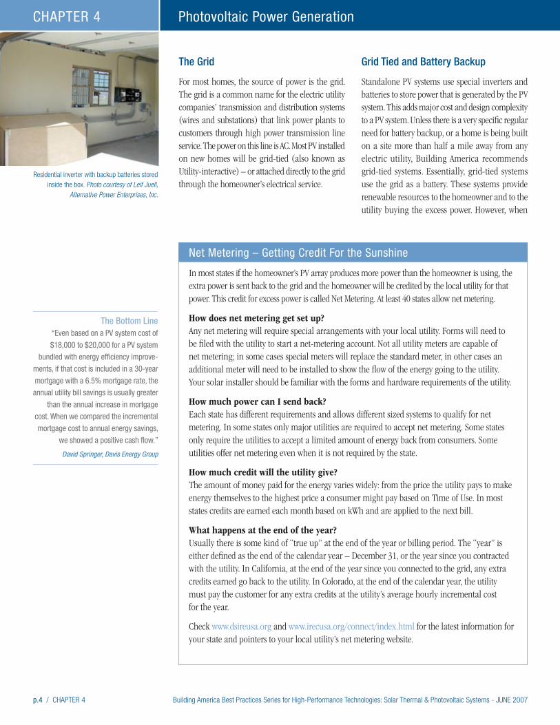
p.4 / CHAPTER 4 Building America Best Practices Series for High-Performance Technologies: Solar Thermal & Photovoltaic Systems - JUNE 2007
Photovoltaic Power GenerationCHAPTER 4
The Grid
For most homes, the source of power is the grid. The grid is a common name for the electric utility companies’ transmission and distribution systems (wires and substations) that link power plants to customers through high power transmission line service. The power on this line is AC. Most PV installed on new homes will be grid-tied (also known as Utility-interactive) – or attached directly to the grid through the homeowner’s electrical service.
Grid Tied and Battery Backup
Standalone PV systems use special inverters and batteries to store power that is generated by the PV system. This adds major cost and design complexity to a PV system. Unless there is a very specific regular need for battery backup, or a home is being built on a site more than half a mile away from any electric utility, Building America recommends grid-tied systems. Essentially, grid-tied systems use the grid as a battery. These systems provide renewable resources to the homeowner and to the utility buying the excess power. However, when
Residential inverter with backup batteries stored inside the box. Photo courtesy of Leif Juell,
Alternative Power Enterprises, Inc.
Net Metering – Getting Credit For the Sunshine
In most states if the homeowner’s PV array produces more power than the homeowner is using, the extra power is sent back to the grid and the homeowner will be credited by the local utility for that power. This credit for excess power is called Net Metering. At least 40 states allow net metering.
How does net metering get set up? Any net metering will require special arrangements with your local utility. Forms will need to be filed with the utility to start a net-metering account. Not all utility meters are capable of net metering; in some cases special meters will replace the standard meter, in other cases an additional meter will need to be installed to show the flow of the energy going to the utility. Your solar installer should be familiar with the forms and hardware requirements of the utility.
How much power can I send back? Each state has different requirements and allows different sized systems to qualify for net metering. In some states only major utilities are required to accept net metering. Some states only require the utilities to accept a limited amount of energy back from consumers. Some utilities offer net metering even when it is not required by the state.
How much credit will the utility give? The amount of money paid for the energy varies widely: from the price the utility pays to make energy themselves to the highest price a consumer might pay based on Time of Use. In most states credits are earned each month based on kWh and are applied to the next bill.
What happens at the end of the year? Usually there is some kind of “true up” at the end of the year or billing period. The “year” is either defined as the end of the calendar year – December 31, or the year since you contracted with the utility. In California, at the end of the year since you connected to the grid, any extra credits earned go back to the utility. In Colorado, at the end of the calendar year, the utility must pay the customer for any extra credits at the utility’s average hourly incremental cost for the year.
Check www.dsireusa.org and www.irecusa.org/connect/index.html for the latest information for your state and pointers to your local utility’s net metering website.
The Bottom Line
“Even based on a PV system cost of
$18,000 to $20,000 for a PV system
bundled with energy efficiency improve-
ments, if that cost is included in a 30-year
mortgage with a 6.5% mortgage rate, the
annual utility bill savings is usually greater
than the annual increase in mortgage
cost. When we compared the incremental
mortgage cost to annual energy savings,
we showed a positive cash flow.” David Springer, Davis Energy Group

Building America Best Practices Series for High-Performance Technologies: Solar Thermal & Photovoltaic Systems - JUNE 2007 CHAPTER 4 / p.5
Photovoltaic Power Generation CHAPTER 4
the grid is not functioning (there is a blackout), the grid-tied PV system does not provide power to the house. Facilities that offer emergency services during disasters are good candidates for battery backup systems. Candidates would include clinics, fire stations, police departments, and dispatch facilities.
Inverter
In many respects the inverter is the most complex component in a PV system. An inverter takes DC current and shapes it into AC current. With a grid-tied system the inverter “listens” to the AC current being delivered to the house and “echoes” the sine wave shape and timing of the wave of power being delivered. This way the PV power that is received by the house looks just like grid power. When more power is generated than is needed by the house, the extra power will blend seamlessly back into the grid for use by other houses or electrical loads in the utility system.
If the utility goes down and there is no power coming from the grid, the inverter will turn off since there is nothing to echo. This feature
helps to ensure the safety of linemen working to fix the grid. Unless there are batteries involved in the PV system, no power will be available to the household when the grid is down. This may be surprising to homeowners, since their system will be capable of generating power, but without batteries and a special inverter to switch to the battery back up no solar power will be available to use until the grid comes back up and the system automatically restarts.
As the most complex part of the system, the inverter literally takes the heat of converting DC to AC power. Like other electronic equipment, inverters must dissipate heat. Inverters may be designed for either indoor or outdoor installations, but indoor installations are more common and provide better protection. It is important to plan on space for the inverter to be located near the main electrical panel. Inverter innovation has made large technical strides in the last 10 years. Inverters are becoming more efficient, durable, and versatile, and some can handle multiple strings of PV modules with varying voltages.
Grid-tied inverters should meet UL Standard 1741.
Grid tied inverters. One mounted on a California garage wall, the other in a Maryland basement. The remote display can be placed anywhere in the house for consumers to keep tabs on power production. Web-based services are also available to monitor PV system performance. Builders need to plan ahead to save space for the inverter and breakers.
Recent Innovations: Inverters with
10 year warranties are now available in
the U.S. European style non-grounded
inverters are allowed by the 2006 NEC
(NEC 690.35) code, although not all
jurisdictions have adopted the most
recent versions of the code. Remote
sensors allow consumers to read
inverter output anywhere in their house.
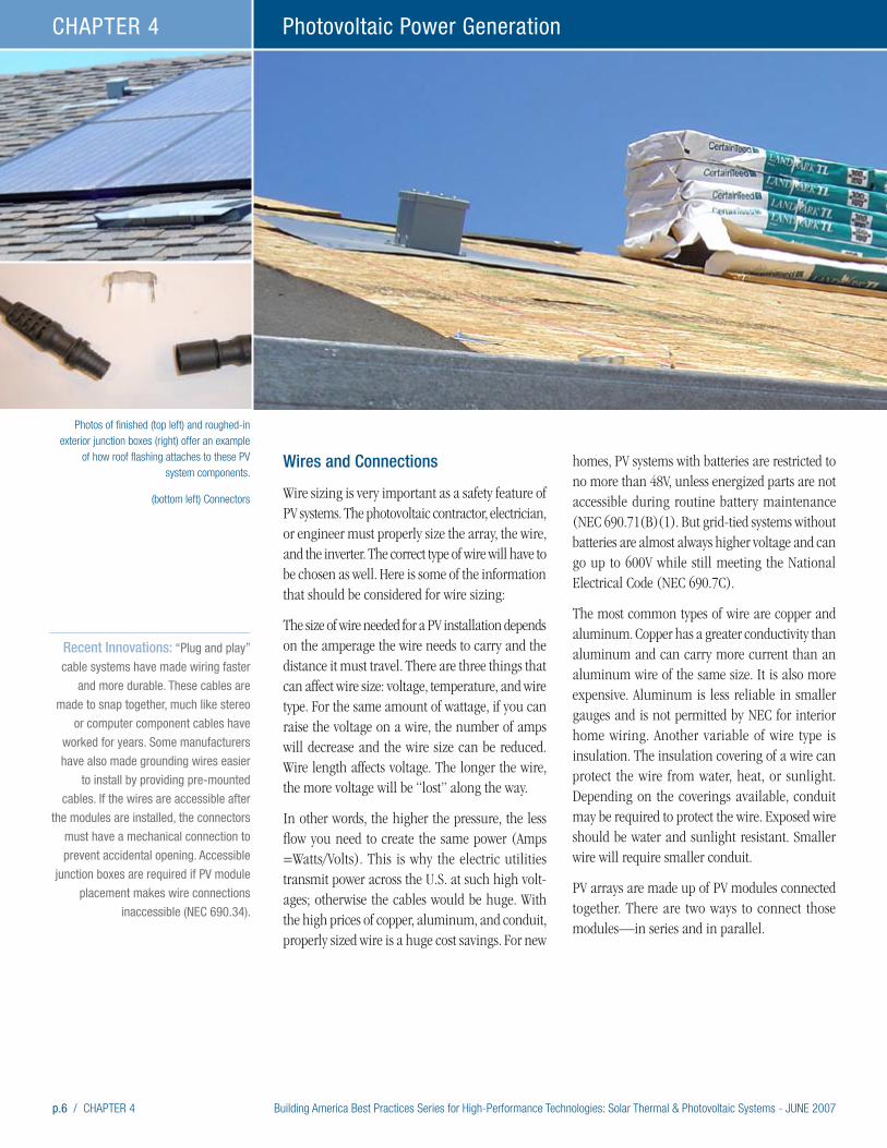
p.6 / CHAPTER 4 Building America Best Practices Series for High-Performance Technologies: Solar Thermal & Photovoltaic Systems - JUNE 2007
Photovoltaic Power GenerationCHAPTER 4
Wires and Connections
Wire sizing is very important as a safety feature of PV systems. The photovoltaic contractor, electrician, or engineer must properly size the array, the wire, and the inverter. The correct type of wire will have to be chosen as well. Here is some of the information that should be considered for wire sizing:
The size of wire needed for a PV installation depends on the amperage the wire needs to carry and the distance it must travel. There are three things that can affect wire size: voltage, temperature, and wire type. For the same amount of wattage, if you can raise the voltage on a wire, the number of amps will decrease and the wire size can be reduced. Wire length affects voltage. The longer the wire, the more voltage will be “lost” along the way.
In other words, the higher the pressure, the less flow you need to create the same power (Amps =Watts/Volts). This is why the electric utilities transmit power across the U.S. at such high volt-ages; otherwise the cables would be huge. With the high prices of copper, aluminum, and conduit, properly sized wire is a huge cost savings. For new
homes, PV systems with batteries are restricted to no more than 48V, unless energized parts are not accessible during routine battery maintenance (NEC 690.71(B)(1). But grid-tied systems without batteries are almost always higher voltage and can go up to 600V while still meeting the National Electrical Code (NEC 690.7C).
The most common types of wire are copper and aluminum. Copper has a greater conductivity than aluminum and can carry more current than an aluminum wire of the same size. It is also more expensive. Aluminum is less reliable in smaller gauges and is not permitted by NEC for interior home wiring. Another variable of wire type is insulation. The insulation covering of a wire can protect the wire from water, heat, or sunlight. Depending on the coverings available, conduit may be required to protect the wire. Exposed wire should be water and sunlight resistant. Smaller wire will require smaller conduit.
PV arrays are made up of PV modules connected together. There are two ways to connect those modules—in series and in parallel.
Photos of finished (top left) and roughed-in exterior junction boxes (right) offer an example
of how roof flashing attaches to these PV system components.
(bottom left) Connectors
Recent Innovations: “Plug and play”
cable systems have made wiring faster
and more durable. These cables are
made to snap together, much like stereo
or computer component cables have
worked for years. Some manufacturers
have also made grounding wires easier
to install by providing pre-mounted
cables. If the wires are accessible after
the modules are installed, the connectors
must have a mechanical connection to
prevent accidental opening. Accessible
junction boxes are required if PV module
placement makes wire connections
inaccessible (NEC 690.34).
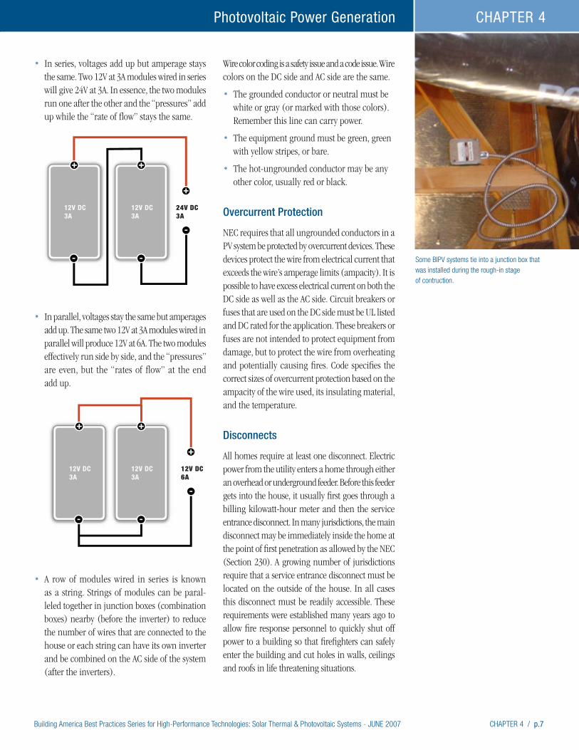
Building America Best Practices Series for High-Performance Technologies: Solar Thermal & Photovoltaic Systems - JUNE 2007 CHAPTER 4 / p.7
Photovoltaic Power Generation CHAPTER 4
• In series, voltages add up but amperage stays the same. Two 12V at 3A modules wired in series will give 24V at 3A. In essence, the two modules run one after the other and the “pressures” add up while the “rate of flow” stays the same.
• In parallel, voltages stay the same but amperages add up. The same two 12V at 3A modules wired in parallel will produce 12V at 6A. The two modules effectively run side by side, and the “pressures” are even, but the “rates of flow” at the end add up.
• A row of modules wired in series is known as a string. Strings of modules can be paral-leled together in junction boxes (combination boxes) nearby (before the inverter) to reduce the number of wires that are connected to the house or each string can have its own inverter and be combined on the AC side of the system (after the inverters).
Wire color coding is a safety issue and a code issue. Wire colors on the DC side and AC side are the same.
• The grounded conductor or neutral must be white or gray (or marked with those colors). Remember this line can carry power.
• The equipment ground must be green, green with yellow stripes, or bare.
• The hot-ungrounded conductor may be any other color, usually red or black.
Overcurrent Protection
NEC requires that all ungrounded conductors in a PV system be protected by overcurrent devices. These devices protect the wire from electrical current that exceeds the wire’s amperage limits (ampacity). It is possible to have excess electrical current on both the DC side as well as the AC side. Circuit breakers or fuses that are used on the DC side must be UL listed and DC rated for the application. These breakers or fuses are not intended to protect equipment from damage, but to protect the wire from overheating and potentially causing fires. Code specifies the correct sizes of overcurrent protection based on the ampacity of the wire used, its insulating material, and the temperature.
Disconnects
All homes require at least one disconnect. Electric power from the utility enters a home through either an overhead or underground feeder. Before this feeder gets into the house, it usually first goes through a billing kilowatt-hour meter and then the service entrance disconnect. In many jurisdictions, the main disconnect may be immediately inside the home at the point of first penetration as allowed by the NEC (Section 230). A growing number of jurisdictions require that a service entrance disconnect must be located on the outside of the house. In all cases this disconnect must be readily accessible. These requirements were established many years ago to allow fire response personnel to quickly shut off power to a building so that firefighters can safely enter the building and cut holes in walls, ceilings and roofs in life threatening situations.
Some BIPV systems tie into a junction box that was installed during the rough-in stage of contruction.
12V DC3A
12V DC3A
12V DC6A
12V DC3A
12V DC3A
24V DC3A
12V DC3A
12V DC3A
12V DC6A
12V DC3A
12V DC3A
24V DC3A

p.8 / CHAPTER 4 Building America Best Practices Series for High-Performance Technologies: Solar Thermal & Photovoltaic Systems - JUNE 2007
Photovoltaic Power GenerationCHAPTER 4
Exterior disconnect.
In homes with PV systems, the NEC (section 690.14) requires supplementary disconnects in addition to the main feeder disconnect. One required PV disconnect is between the PV arrays and the inverter. If the attic is readily accessible with permanent stairs, and the PV is on the roof, this disconnect may be near the point where the output wire from the PV array first enters the house. Or, the disconnect may be right next to the inverter if the DC conductors are in a metallic raceway or pre-assembled metal clad cable. Some inverters have incorporated a disconnect switch into a box attached to the inverter.
The NEC requires that each piece of PV equipment have disconnect switches allowing service providers to disconnect the equipment from all sources of power. For example, an inverter must have a disconnect between it and the array, and between the inverter and the panel. The disconnects may be circuit breakers or switches (Section 690.17). DC-rated switches are expensive; therefore, the ready availability of moderately priced DC-rated circuit breakers with ratings up to 125 volts and 110 amps may be a good choice for use in all 12-, 24-, and 48-volt systems. When properly located and used within their approved ratings, circuit breakers can serve as both the disconnect and an overcurrent device.
In grid-tied systems, the number of disconnects depends on the complexity of the system. In a simple system there would be disconnects on both sides of the inverter, in addition to the main feed disconnect required on all houses. In more complex systems, there may be disconnect switches for each string of arrays, sub-array disconnects, main PV disconnects for each inverter, sub-panel and AC disconnect (you can only have one AC disconnect per utility service). If there are multiple inverters they must be combined in a dedicated subpanel that feeds one AC disconnect) and a main feed AC disconnect.
Disconnect switches must be rated to carry appropri-ate levels of current and have appropriate voltage and interrupt ratings (NEC Section 110.3(B)).
Recent Innovation: Modern inverters may also include integrated DC disconnect switches. In
these systems, a separate DC side disconnect may not be required.
Main Electrical Panel
Usually power from the inverter is pushed (backfed) into the main service panel of a house through a circuit breaker. The number of amps that can be pushed through is dependent on the original size of the electrical panel (load center). The sum of the rating of all breakers supplying power to a panel must not exceed 120% of the panel rating. The backfed PV breakers and the main breaker supply power to the panel (NEC 690.64B). For example a panel rated at 100A with a 100A main breaker can have 20A additional backfed from a PV system.
If the system being installed is larger than 20% of the panel rating, there are other ways to connect to the main panel, but these require specific electrical design.
Grounding
NEC 2005 requires any PV system carrying more than 50V to be grounded (NEC 690.41), unless specific requirements are met (found at NEC 690.35). These types of systems are common in other countries. Also, PV systems must have their equipment grounded—even at only 12V (NEC 690.43). Grounding limits problems due to lightning and other line surges and makes the system safer for people working on and around the system.
There are two types of grounding—equipment grounding and system grounding.
• Equipment grounding is done to prevent shock when touching metal parts that don’t usually carry electricity (for example the frames of the modules, the junction boxes, appliances). If any of the exposed metal is touched by a live wire the metal becomes electrified as well – this is called a ground fault. A person who touches this live part will complete the circuit and be shocked. To solve this problem all exposed metal parts are wired to the grounding electrode. The grounding system must connect every exposed
Recent Innovations: As of NEC 2005,
ungrounded systems are permitted
(not required) in the United States.
(NEC 690.35) PV installations in Europe
and Japan have been ungrounded
for decades, but this is new technol-
ogy for North America. Allowing this
technology will bring smaller, lighter, less
expensive inverters from Europe. The
inverters don’t need internal isolation
transformers so they weigh less. This
change requires the use of listed PV wire
technology—double insulated single
conductor wires. Use of ungrounded
systems will require training on the
installer/electrician side and the inspec-
tor side of solar installations.

Building America Best Practices Series for High-Performance Technologies: Solar Thermal & Photovoltaic Systems - JUNE 2007 CHAPTER 4 / p.9
Photovoltaic Power Generation CHAPTER 4
non-current-carrying part of the installation to ground. The equipment ground wire is either green, green with yellow stripes, or bare.
• System grounding takes one current-carrying conductor and attaches it to ground. On the DC side that is the negative or positive (depending on the inverter and module specifications) conductor (white or gray wire); on the AC side it’s the neutral conductor (white or gray wire). The closer the grounding connection can be to the PV source the better the protection from surges due to lightning.
• When servicing you must be able to remove a module without breaking the system ground circuit. Some modules on the market are not compliant with this code issue. Ensure that modules for your job meet this code requirement.
BIPV Systems: A New Way of Putting the Pieces TogetherFundamentally, all PV systems have similar compo-nents and work in similar ways. At the beginning of this chapter was a diagram of a generic system. Although systems work in similar ways, they do
have different architectural styles and engineering methods for how they are integrated with a house in order to take advantage of the unique characteristics of module materials.
Even though their use is more widespread, PV systems have become much more difficult to spot on rooftops. Building integrated systems are literally built into the building and have the same profile as nearby materials.
Most PV systems still mount on racks, but many of these systems have such a low profile they appear to be thin skylights. A review of products available in the U.S. can be found in the November 2005 issue of Energy Design Update (EDU 2005). Mounting systems that place PV arrays very close to the roof surface, but not actually integrated into the roof, are described in Chapter 6: Solar System Mounts. More traditional rack systems are also described.
BIPV stands for Building Integrated Photovoltaics. These systems represent a major innovation in incorporating PV into residential architecture. BIPV systems are PV arrays that also serve as an integral part of the building. The PV arrays usually replace other parts of the shell – typically roofing material.
Recent Innovations: Module
manufacturers are providing grounding
screws and pre-installing cables to
ease installation.
Recent Innovations: Building
Integrated and direct mount systems
hide most hardware, are difficult to
spot, and use the array to cover most
roof penetrations, helping to keep
penetrations out of the direct weather.
Standard Fire Ratings for Roof Coverings – UL 790
Three classes of fire exposure are described:
Class A roof coverings are effective against severe fire test exposures. Under such exposures, roof coverings of this class afford a high degree of fire protection to the roof deck, do not slip from position, and are not expected to produce flying brands (burning objects).
Class B roof coverings are effective against moderate fire test exposures. Under such exposures, roof coverings of this class afford a moderate degree of fire protection to the roof deck, do not slip from position, and are not expected to produce flying brands.
Class C roof coverings are effective against light fire test exposures. Under such exposures, roof coverings of this class afford a light degree of fire protection to the roof deck, do not slip from position, and are not expected to produce flying brands.

p.10 / CHAPTER 4 Building America Best Practices Series for High-Performance Technologies: Solar Thermal & Photovoltaic Systems - JUNE 2007
Photovoltaic Power GenerationCHAPTER 4
Cement Tile Systems
Perhaps the most popular integrated system in the U.S. is made up of PV modules that are sized and mounted to replace cement tiles. The most common systems use mono- or poly-crystalline cells. The PV tiles are installed on roofs in a way that blends in with cement tiles. The PV tiles follow the contour of the roof in exactly the same way as do the cement tiles. Electrical connections are made between each tile. In some cases a single module will replace a set of three or four tiles, reducing the number of connections. Many of these tiles, when installed according to manufacturer specifications, are Class A fire resistant.
The PV arrays weigh less than the cement tiles they replace. But the roof must be engineered for the correct weight and any supporting structure is done in advance. Since these products are replacing roofing material and are the first line of defense against the elements, they should be compliant with local and national roofing requirements. Some BIPV products have been tested by UL as a Listed roofing material under UL 790 (Class A Fire) and UL 997 (110 wind rating), as well as UL 1703 (PV
Module). In addition the ICC recently established acceptance criteria to provide guidance for the evaluation of BIPV roof panels (ICC 2006). Builders should ask installers or other suppliers to confirm that BIPV systems meet these standards.
Each manufacturer has specific requirements for its product. One product selected as an example is the SunPower SunTile. These PV tiles are placed on top of an underlayment that covers the roof deck. The underlayment helps to provide Class A fire rating. The following text and photos describe the installation sequence for this product.
Photo numbers correspond to paragraph numbers. Not all paragraphs have a corresponding photo.
∂ After framing but before insulation and sheetrock are installed the house is prewired for the PV array. Metallic armored cable is run from a loose junction box placed near the roof to the point where the inverter will be installed. Rough-in boxes are installed as end points for the cable. The inverter is installed and lines are run to the shutoff on the AC side and to the main panel. This product is lighter than the tiles replaced, so no extra structural support is needed.
Here are some of the currently available cement
tile type PV systems:
EnergyTile – BP Solar
GEPV-055 – GE Energy
MyGen | Meridian – Kyocera
ND-62RU1 – Sharp Solar
SolarSave – Open Energy Corporation
SunSlates – Atlantis
SunPower
(photo series) Cement tile system step-by-step installation
Photo numbers correspond to paragraph numbers. Not all paragraphs have a
corresponding photo.
∂ ∑ ∏
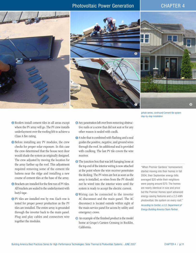
Building America Best Practices Series for High-Performance Technologies: Solar Thermal & Photovoltaic Systems - JUNE 2007 CHAPTER 4 / p.11
Photovoltaic Power Generation CHAPTER 4
(photo series, continued) Cement tile system step-by-step installation
∑ Roofers install cement tiles in all areas except where the PV array will go. The PV crew installs underlayment over the roofing felt to achieve a Class A fire rating.
∏ Before installing any PV modules, the crew checks for proper solar exposure. In this case the crew determined that the house next door would shade the system as originally designed. The crew adjusted by moving the location for the array farther up the roof. This adjustment required removing some of the cement tile battens near the ridge and installing a new course of cement tiles at the base of the array.
π Brackets are installed for the first run of PV tiles. All brackets are sealed to the underlayment with butyl tape.
∫ PV tiles are installed row by row. Each row is tested for proper power production as the PV tiles are installed. The entire array is grounded through the inverter back to the main panel. Plug and play cables and connectors wire together the modules.
ª Any penetration left over from removing obstruc-tive nails or a screw that did not seat or for any other reason is sealed with caulk.
º A tube that is combined with flashing and a seal guides the positive, negative, and ground wires through the roof. An additional seal is provided with caulking. The last PV tile covers the wire receiver.
Ω The junction box that was left hanging loose at the top end of the interior wiring is now attached at the point where the wire receiver penetrates the decking. The PV wires are hot as soon as the array is installed, so wires from the PV should not be wired into the interior wires until the system is ready to accept the electric current.
æ Wiring can be connected to the inverter AC disconnect and the main panel. The AC disconnect is located outside within sight of the main service panel for access by utility and emergency crews.
ø An example of the finished product is the model home at Grupe’s Carsten Crossing in Rocklin, California.
∫
º øπ
“When Premier Gardens’ homeowners
started moving into their homes in fall
2004, their September energy bills
averaged $20 while their neighbors
were paying around $70. The homes
are nearly identical in size and price
but the Premier Homes sport advanced
energy-saving features and a 2.2-kWh
photovoltaic tile system on every roof.” According to ConSol, a U.S. Department of
Energy Building America Team Partner.

p.12 / CHAPTER 4 Building America Best Practices Series for High-Performance Technologies: Solar Thermal & Photovoltaic Systems - JUNE 2007
Photovoltaic Power GenerationCHAPTER 4
Thin Film PV Laminate for Raised Seam Metal Roofs
One interesting place to put solar is on a metal standing seam roof. This laminate on soft plastic rolls out to fit between the seams. While this does not replace the metal on the roof, it is directly attached with glue during installation of the roof. The electrical connections are made under the roof ridge (an easily accessible place for maintenance). The systems are easy to install with no additional structural support required. The system is produced by Uni-Solar Laminates – Uni-Solar Ovionics.
Examples of installations of metal standing seam roof laminate systems follow. Photo numbers corre-spond to paragraph numbers. Not all paragraphs have a corresponding photo.
∂After framing but before insulation and sheetrock are installed the house is pre-wired for the PV array. Metallic armored cable is run from a loose junction box placed near the roof to the point where the inverter will be installed. Rough-in boxes are installed as end points for the cable. The inverter is installed and lines are run to the
shutoff on the AC side and to the main panel. No extra structural support is needed for this product. Preparation may include providing conduit races through the peak to run wires.
∑ The metal roof must have steel pans that are at least 16” wide. They must be flat surfaced with no pencil beading or decorative stippling.
∏ The pans must be cleaned well to the manu-facturer’s specifications.
π The laminate is installed onto the pans before the pans are installed on the roof. The laminate comes in pre-cut rolls and comes with the glue already adhered to one side. Peel the protective covering and adhere the laminate to the pan. Make sure there are no bubbles. This job could be completed in a shop to maintain a clean surface and to keep materials out of the weather.
∫ Install the pans on the roof normally with the wires facing the peak.
ª There are no penetrations in the pans with this type of solar array, reducing the possibility of leaks.
º The wires are connected along the ridge of the roof and covered later by the ridge cap. The
∂ ∑
(photo series) Metal standing seam roof laminate systems step-by-step installation.
(above) Photo courtesy of Leif Juell, Alternative Power Enterprises, Inc.
Photo numbers correspond to paragraph numbers. Not all paragraphs have a
corresponding photo.
Photo courtesy of Decker Homes. Photo courtesy of Decker Homes.
π
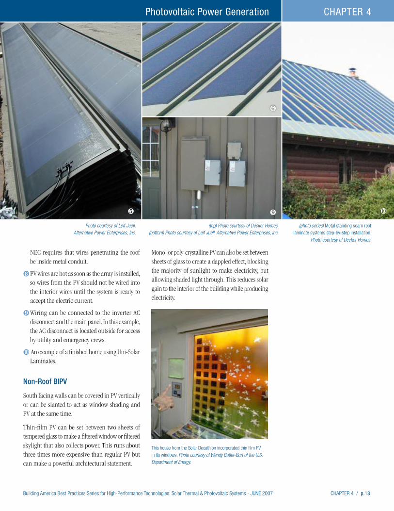
Building America Best Practices Series for High-Performance Technologies: Solar Thermal & Photovoltaic Systems - JUNE 2007 CHAPTER 4 / p.13
Photovoltaic Power Generation CHAPTER 4
NEC requires that wires penetrating the roof be inside metal conduit.
Ω PV wires are hot as soon as the array is installed, so wires from the PV should not be wired into the interior wires until the system is ready to accept the electric current.
æ Wiring can be connected to the inverter AC disconnect and the main panel. In this example, the AC disconnect is located outside for access by utility and emergency crews.
ø An example of a finished home using Uni-Solar Laminates.
Non-Roof BIPV
South facing walls can be covered in PV vertically or can be slanted to act as window shading and PV at the same time.
Thin-film PV can be set between two sheets of tempered glass to make a filtered window or filtered skylight that also collects power. This runs about three times more expensive than regular PV but can make a powerful architectural statement.
Mono- or poly-crystalline PV can also be set between sheets of glass to create a dappled effect, blocking the majority of sunlight to make electricity, but allowing shaded light through. This reduces solar gain to the interior of the building while producing electricity.
(photo series) Metal standing seam roof laminate systems step-by-step installation.
Photo courtesy of Decker Homes.
Photo courtesy of Leif Juell, Alternative Power Enterprises, Inc.
(top) Photo courtesy of Decker Homes. (bottom) Photo courtesy of Leif Juell, Alternative Power Enterprises, Inc.
∫
ª
æ
This house from the Solar Decathlon incorporated thin film PV in its windows. Photo courtesy of Wendy Butler-Burt of the U.S. Department of Energy.
ø
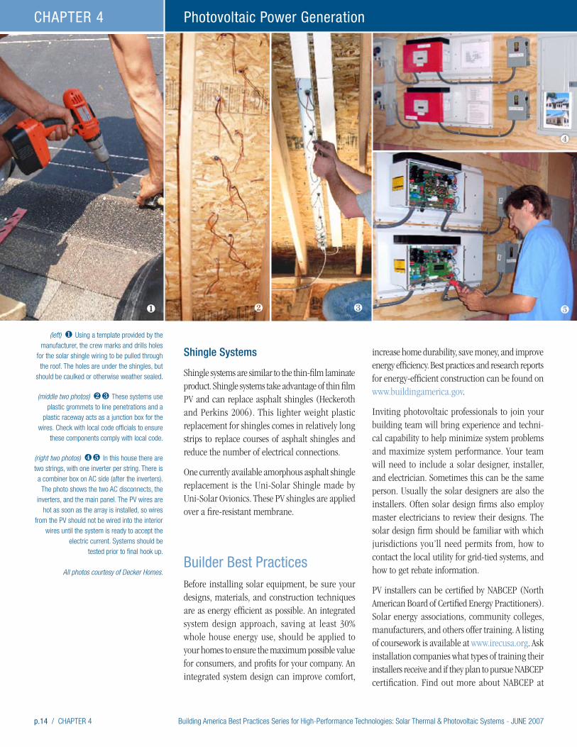
p.14 / CHAPTER 4 Building America Best Practices Series for High-Performance Technologies: Solar Thermal & Photovoltaic Systems - JUNE 2007
Photovoltaic Power GenerationCHAPTER 4
Shingle Systems
Shingle systems are similar to the thin-film laminate product. Shingle systems take advantage of thin film PV and can replace asphalt shingles (Heckeroth and Perkins 2006). This lighter weight plastic replacement for shingles comes in relatively long strips to replace courses of asphalt shingles and reduce the number of electrical connections.
One currently available amorphous asphalt shingle replacement is the Uni-Solar Shingle made by Uni-Solar Ovionics. These PV shingles are applied over a fire-resistant membrane.
Builder Best PracticesBefore installing solar equipment, be sure your designs, materials, and construction techniques are as energy efficient as possible. An integrated system design approach, saving at least 30% whole house energy use, should be applied to your homes to ensure the maximum possible value for consumers, and profits for your company. An integrated system design can improve comfort,
increase home durability, save money, and improve energy efficiency. Best practices and research reports for energy-efficient construction can be found on www.buildingamerica.gov.
Inviting photovoltaic professionals to join your building team will bring experience and techni-cal capability to help minimize system problems and maximize system performance. Your team will need to include a solar designer, installer, and electrician. Sometimes this can be the same person. Usually the solar designers are also the installers. Often solar design firms also employ master electricians to review their designs. The solar design firm should be familiar with which jurisdictions you’ll need permits from, how to contact the local utility for grid-tied systems, and how to get rebate information.
PV installers can be certified by NABCEP (North American Board of Certified Energy Practitioners). Solar energy associations, community colleges, manufacturers, and others offer training. A listing of coursework is available at www.irecusa.org. Ask installation companies what types of training their installers receive and if they plan to pursue NABCEP certification. Find out more about NABCEP at
(left) ∂ Using a template provided by the manufacturer, the crew marks and drills holes
for the solar shingle wiring to be pulled through the roof. The holes are under the shingles, but
should be caulked or otherwise weather sealed.
(middle two photos) ∑∏ These systems use plastic grommets to line penetrations and a
plastic raceway acts as a junction box for the wires. Check with local code officials to ensure
these components comply with local code.
(right two photos) π∫ In this house there are two strings, with one inverter per string. There is a combiner box on AC side (after the inverters).
The photo shows the two AC disconnects, the inverters, and the main panel. The PV wires are
hot as soon as the array is installed, so wires from the PV should not be wired into the interior
wires until the system is ready to accept the electric current. Systems should be
tested prior to final hook up.
All photos courtesy of Decker Homes.
∂ ∑
π
∫∏
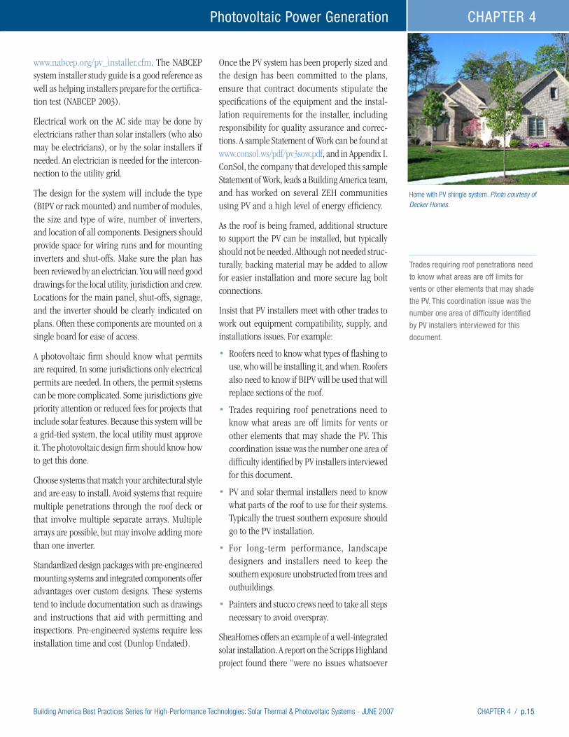
Building America Best Practices Series for High-Performance Technologies: Solar Thermal & Photovoltaic Systems - JUNE 2007 CHAPTER 4 / p.15
Photovoltaic Power Generation CHAPTER 4
www.nabcep.org/pv_installer.cfm. The NABCEP system installer study guide is a good reference as well as helping installers prepare for the certifica-tion test (NABCEP 2003).
Electrical work on the AC side may be done by electricians rather than solar installers (who also may be electricians), or by the solar installers if needed. An electrician is needed for the intercon-nection to the utility grid.
The design for the system will include the type (BIPV or rack mounted) and number of modules, the size and type of wire, number of inverters, and location of all components. Designers should provide space for wiring runs and for mounting inverters and shut-offs. Make sure the plan has been reviewed by an electrician. You will need good drawings for the local utility, jurisdiction and crew. Locations for the main panel, shut-offs, signage, and the inverter should be clearly indicated on plans. Often these components are mounted on a single board for ease of access.
A photovoltaic firm should know what permits are required. In some jurisdictions only electrical permits are needed. In others, the permit systems can be more complicated. Some jurisdictions give priority attention or reduced fees for projects that include solar features. Because this system will be a grid-tied system, the local utility must approve it. The photovoltaic design firm should know how to get this done.
Choose systems that match your architectural style and are easy to install. Avoid systems that require multiple penetrations through the roof deck or that involve multiple separate arrays. Multiple arrays are possible, but may involve adding more than one inverter.
Standardized design packages with pre-engineered mounting systems and integrated components offer advantages over custom designs. These systems tend to include documentation such as drawings and instructions that aid with permitting and inspections. Pre-engineered systems require less installation time and cost (Dunlop Undated).
Once the PV system has been properly sized and the design has been committed to the plans, ensure that contract documents stipulate the specifications of the equipment and the instal-lation requirements for the installer, including responsibility for quality assurance and correc-tions. A sample Statement of Work can be found at www.consol.ws/pdf/pv3sow.pdf, and in Appendix I. ConSol, the company that developed this sample Statement of Work, leads a Building America team, and has worked on several ZEH communities using PV and a high level of energy efficiency.
As the roof is being framed, additional structure to support the PV can be installed, but typically should not be needed. Although not needed struc-turally, backing material may be added to allow for easier installation and more secure lag bolt connections.
Insist that PV installers meet with other trades to work out equipment compatibility, supply, and installations issues. For example:
• Roofers need to know what types of flashing to use, who will be installing it, and when. Roofers also need to know if BIPV will be used that will replace sections of the roof.
• Trades requiring roof penetrations need to know what areas are off limits for vents or other elements that may shade the PV. This coordination issue was the number one area of difficulty identified by PV installers interviewed for this document.
• PV and solar thermal installers need to know what parts of the roof to use for their systems. Typically the truest southern exposure should go to the PV installation.
• For long-term performance, landscape designers and installers need to keep the southern exposure unobstructed from trees and outbuildings.
• Painters and stucco crews need to take all steps necessary to avoid overspray.
SheaHomes offers an example of a well-integrated solar installation. A report on the Scripps Highland project found there “were no issues whatsoever
Home with PV shingle system. Photo courtesy of Decker Homes.
π
Trades requiring roof penetrations need
to know what areas are off limits for
vents or other elements that may shade
the PV. This coordination issue was the
number one area of difficulty identified
by PV installers interviewed for this
document.

p.16 / CHAPTER 4 Building America Best Practices Series for High-Performance Technologies: Solar Thermal & Photovoltaic Systems - JUNE 2007
Photovoltaic Power GenerationCHAPTER 4
regarding roof penetrations (and any leaks as a result of)” at the project. The report notes that the systems were installed with a roof penetra-tion flashing system, the design of which was supported by the roofing company involved in the installation. “That, in all likelihood, made a substantial difference in the success of the project, by engaging the existing roofing subcontractor in the decision-making process, and calling upon the company’s expertise in roofing and flashing techniques (Nelson 2005).”
After exterior sheathing is installed, solar mounts and junction boxes may be installed. While on the roof, the solar installer should spray paint the boundaries needed for the PV modules and sections of the roof that should be off limits to other penetrations that may cause shading or that will be blocked by the array.
The best time to install PV modules will depend on the product being used and accommodations worked out with trades. It may be advantageous to wait until after exterior painting. Waiting avoids problems with overspray on solar collector glazing or PV modules.
Production builders should be using a quality assurance process that includes pressurization tests for the house and duct work. Quality assurance should also include the inspection and testing of all solar thermal and PV equipment. Experience has shown that when inspections are done, failure rates on solar thermal systems are very low, much less than 1%. Train your quality inspection staff or sub contractor, or hire a specialty sub-contractor, to test and inspect solar systems. Local utilities may help with this function. Inspection guidance for codes officials (which should be readily adaptable for quality assurance) is available at www.irecusa.org. A detailed testing protocol has been developed by the National Renewable Energy Laboratory and is available at www.nrel.gov/docs/fy03osti/30301.pdf. A quality assurance checklist, developed by ConSol, a team leader for Building America, is available at www.consol.ws/pdf/PV4Checklist.pdf and in Appendix I. Sources for other checklists are listed at the end of the PV Installer Best Practices in the next section.
PV Installer Best PracticesThis document does not provide detailed technical best practices for installers. Other references, listed in the Additional Information section can help with details. What this section does do is provide insights into working with production builders.
Work with the builder and his or her designers to draw the PV system into the plans. System loca-tion may change with orientation and site access, but putting the system on the plans alerts other subcontractors, site supervisors, and inspectors that the systems are going in. The plans should include predetermined locations for inverters and cut off switches. If needed, the plans should also indicate any structural additions added for easier or stronger installations.
Production building incorporates factory-like processes in the field. It is not uncommon to have houses in various stages of construction as one looks down a street. Depending on the size of the project, it is possible that every trade that supports a particular builder will be represented on the job site every day, but working on different houses. PV installers will need to fit into this rhythm. It may be necessary to schedule crews to do pre-installa-tions, array installations, and interior component installations. Different crews may do these tasks simultaneously, or one crew may have different jobs at different times. Be clear with the site supervisor about demands for crew time.
Work with site supervisors, roofers, plumbers, and others to determine the best points in time to be in a house and what materials to provide. Pay attention to other trades that will be working in the same spaces.
• Spray paint roof areas before the finish roof is installed that need to be protected for mounting modules and to maintain solar exposure.
• If arrays go in before house painting is complete, cover them with plastic to protect against over-spray. Wind may carry overspray from nearby houses so check the status of painting on neighboring houses. Remove the plastic when painting is complete or ensure that somebody has that responsibility.
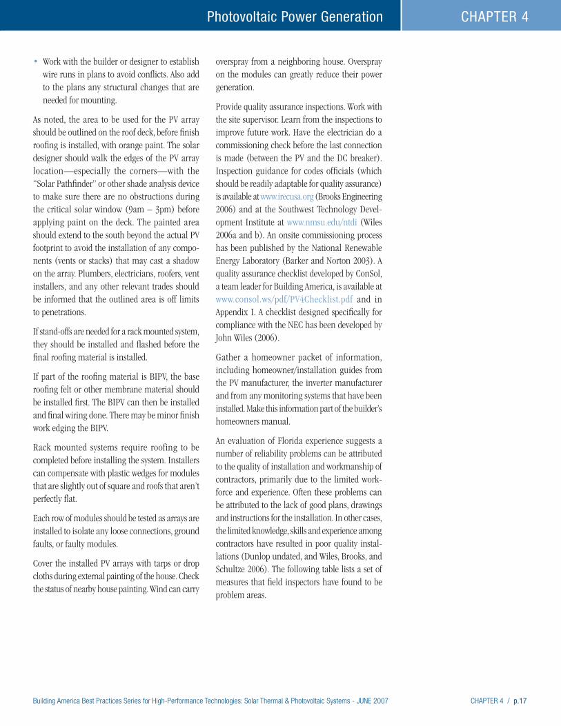
Building America Best Practices Series for High-Performance Technologies: Solar Thermal & Photovoltaic Systems - JUNE 2007 CHAPTER 4 / p.17
Photovoltaic Power Generation CHAPTER 4
• Work with the builder or designer to establish wire runs in plans to avoid conflicts. Also add to the plans any structural changes that are needed for mounting.
As noted, the area to be used for the PV array should be outlined on the roof deck, before finish roofing is installed, with orange paint. The solar designer should walk the edges of the PV array location—especially the corners—with the “Solar Pathfinder” or other shade analysis device to make sure there are no obstructions during the critical solar window (9am – 3pm) before applying paint on the deck. The painted area should extend to the south beyond the actual PV footprint to avoid the installation of any compo-nents (vents or stacks) that may cast a shadow on the array. Plumbers, electricians, roofers, vent installers, and any other relevant trades should be informed that the outlined area is off limits to penetrations.
If stand-offs are needed for a rack mounted system, they should be installed and flashed before the final roofing material is installed.
If part of the roofing material is BIPV, the base roofing felt or other membrane material should be installed first. The BIPV can then be installed and final wiring done. There may be minor finish work edging the BIPV.
Rack mounted systems require roofing to be completed before installing the system. Installers can compensate with plastic wedges for modules that are slightly out of square and roofs that aren’t perfectly flat.
Each row of modules should be tested as arrays are installed to isolate any loose connections, ground faults, or faulty modules.
Cover the installed PV arrays with tarps or drop cloths during external painting of the house. Check the status of nearby house painting. Wind can carry
overspray from a neighboring house. Overspray on the modules can greatly reduce their power generation.
Provide quality assurance inspections. Work with the site supervisor. Learn from the inspections to improve future work. Have the electrician do a commissioning check before the last connection is made (between the PV and the DC breaker). Inspection guidance for codes officials (which should be readily adaptable for quality assurance) is available at www.irecusa.org (Brooks Engineering 2006) and at the Southwest Technology Devel-opment Institute at www.nmsu.edu/ntdi (Wiles 2006a and b). An onsite commissioning process has been published by the National Renewable Energy Laboratory (Barker and Norton 2003). A quality assurance checklist developed by ConSol, a team leader for Building America, is available at www.consol.ws/pdf/PV4Checklist.pdf and in Appendix I. A checklist designed specifically for compliance with the NEC has been developed by John Wiles (2006).
Gather a homeowner packet of information, including homeowner/installation guides from the PV manufacturer, the inverter manufacturer and from any monitoring systems that have been installed. Make this information part of the builder’s homeowners manual.
An evaluation of Florida experience suggests a number of reliability problems can be attributed to the quality of installation and workmanship of contractors, primarily due to the limited work-force and experience. Often these problems can be attributed to the lack of good plans, drawings and instructions for the installation. In other cases, the limited knowledge, skills and experience among contractors have resulted in poor quality instal-lations (Dunlop undated, and Wiles, Brooks, and Schultze 2006). The following table lists a set of measures that field inspectors have found to be problem areas.

p.18 / CHAPTER 4 Building America Best Practices Series for High-Performance Technologies: Solar Thermal & Photovoltaic Systems - JUNE 2007
Photovoltaic Power GenerationCHAPTER 4
Always confirm that solar exposure is unobstructed. Shading is a critical flaw
in installation. (left) Photo courtesy of NREL.
(right) Photo courtesy of
Heidi Stewart of PNNL.
Roof penetrations must be properly flashed and sealed.
Photos courtesy of
Namaste Solar Electric
Wire connections must be properly installed. New “plug-and-play” wires systems help
solve this problem. (left) Photo courtesy of John Wiles of
SWTDI. (right) Photo courtesy of
Kurt Johnson of SunPower
Electrical materials (lugs, screws, wires) selection is critical for
a safe and durable system. In the picture to the left, indoor
rated materials were used for an outdoor grounding application.
(left) Photo courtesy of
John Wiles of SWTDI
THE Wrong WAY THE right WAY
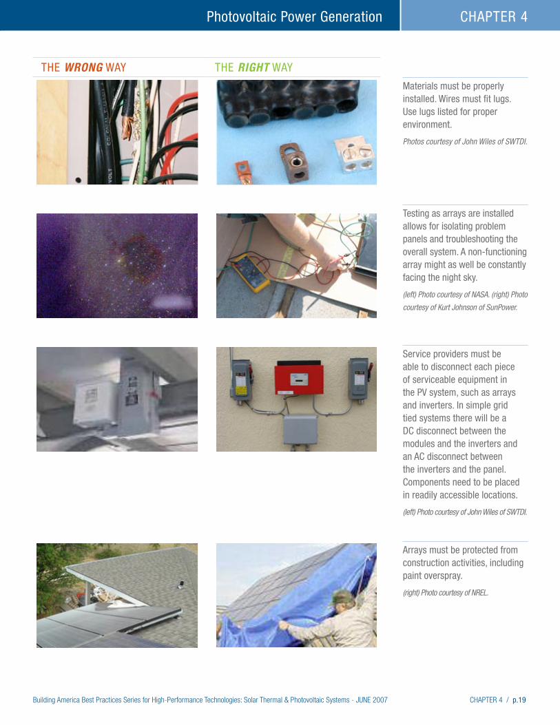
Building America Best Practices Series for High-Performance Technologies: Solar Thermal & Photovoltaic Systems - JUNE 2007 CHAPTER 4 / p.19
Photovoltaic Power Generation CHAPTER 4
THE Wrong WAY THE right WAY
Materials must be properly installed. Wires must fit lugs. Use lugs listed for proper environment. Photos courtesy of John Wiles of SWTDI.
Testing as arrays are installed allows for isolating problem panels and troubleshooting the overall system. A non-functioning array might as well be constantly facing the night sky. (left) Photo courtesy of NASA. (right) Photo
courtesy of Kurt Johnson of SunPower.
Service providers must be able to disconnect each piece of serviceable equipment in the PV system, such as arrays and inverters. In simple grid tied systems there will be a DC disconnect between the modules and the inverters and an AC disconnect between the inverters and the panel. Components need to be placed in readily accessible locations. (left) Photo courtesy of John Wiles of SWTDI.
Arrays must be protected from construction activities, including paint overspray. (right) Photo courtesy of NREL.
p.20 / CHAPTER 4 Building America Best Practices Series for High-Performance Technologies: Solar Thermal & Photovoltaic Systems - JUNE 2007
Photovoltaic Power GenerationCHAPTER 4
Long Term MaintenancePV systems have very simple long term maintenance. These systems should last at least 20 years. Here are the basic steps homeowners need to follow:
• Yearly cleaning of the PV modules or rely on seasonal rain,
• Occasional snow removal – depending on the climate (do not use metal objects to clean glass),
• If any wires are exposed, yearly checking for evidence of hungry critters (like squirrels), and
• Maintaining a performance log to watch for major variations in energy production (non-weather related) to track potential problems. Systems that include web-based monitoring can provide this service.
Resources and References
California Energy Commission (CEC) lists of Eligible Equipment www.consumerenergycenter.org/erprebate/equipment.html
NABCEP – North American Board of Certified Energy Practitioners www.nabcep.org
IREC – Interstate Renewable Energy Council www.irecusa.org
Southwest Technology Development Institute, New Mexico State University www.nmsu.edu/~tdi/
SEI – Solar Energy International www.solarenergy.org
Namaste Solar Electric www.namastesolar.com
FSEC – Florida Solar Energy Center www.fsec.ucf.edu
NREL – National Renewable Energy Laboratory, Solar Research www.nrel.gov/solar/
Barker, G., and P. Norton. 2003. Building America System Performance Test Practices: Part 1 – Photovoltaic Systems. NREL/TP-550-30301. Prepared by the National Renewable Energy Laboratory for the U.S. Department of Energy, Golden, CO. www.nrel.gov/docs/fy03osti/30301.pdf
Brooks Engineering. 2006. Inspector Guidelines for PV Systems. Prepared for the Renewable Energy Technology Analysis Project of the Pace Univeristy Law School Project. Available at www.irecusa.org/articles/static/1/binaries/InspectorGuidelinesDraft9.pdf
Dunlop, Jim. Undated. Reliability and Experience in the Florida PV Buildings Program. Florida Solar Energy Center, Cocoa, FL

Building America Best Practices Series for High-Performance Technologies: Solar Thermal & Photovoltaic Systems - JUNE 2007 CHAPTER 4 / p.21
Photovoltaic Power Generation CHAPTER 4
Energy Design Update (EDU). 2005. “New Products: Photovoltaic Roofing.” Energy Design Update, November 2005. Aspen Publishers, New York. www.aspenpublishers.com
Heckeroth, Stephen and Daniel Perkins. 2006. “The Future of Photovoltaic Roofing Products.” Solar 2006 Conference Proceedings, edited by R. Campbell-Howe. American Solar Energy Society, Boulder, CO.
ICC Evaluation Service, Inc. 2006. Proposed Acceptance Criteria For Building-Integrated Photovoltaic (BIPV) Roof Panels. AC365. Whittier, CA. www.icc-es.org
National Fire Protection Association. 2005. NEC 2005 Handbook: NFPA National Electrical Code, International Electric Code Series. Edited by Mark Earley, Jeffrey Sargent, Joseph Sheehan, and John Caloggero. National Fire Protection Association, Quincy, MA.
Nelson, Les. 2005. Scripps Highlands; A SheaHomes Zero Energy Home Project in the San Diego Area. Prepared by Western Renewables Group for the Sacramento Municipal Utility District.
North American Board of Certified Energy Practitioners (NABCEP). 2003. Study Guide for Photovoltaic Systems Installers and Sample Examination Questions. Originally prepared for the U.S. Department of Energy and Sandia National Laboratories by the Southeast Regional Experimental Station and the Florida Solar Energy Center, Cocoa, FL.
Rudin, Arthur and Edgar Becerra. 2006. Designing Residential PV Systems to Meet Local Wind Loads and Building Codes. Solar 2006 Conference Proceedings, edited by R. Campbell-Howe. American Solar Energy Society, Boulder, CO.
Russell, Scott. 2004. “Solar Electric Systems Simplified.” Home Power, Issue 104, December 2004 and January 2005. www.homepower.com
Wiles, John. 2006a. Photovoltaic Electrical Power Systems Inspector/Installer Checklist. Available at www.nmsu.edu/~tdi/
Wiles, John. 2006b. “Code Corner: Working with Inspectors: What Your Checklist Should Include.” HomePower, Issue 113, June & July 2006. www.homepower.com. Also at www.nmsu.edu/~tdi/
Wiles, John. 2006c. “Achieving the Art of the Possible.” July-August 2006. IAEI News, International Association of Electrical Inspectors. www.IAEI.org. Also at www.nmsu.edu/~tdi/
Wiles, John. 2006d. “The 15-Minute PV System Inspection: Can you? Should you?” May-June 2006. IAEI News, International Association of Electrical Inspectors. www.IAEI.org. Also at www.nmsu.edu/~tdi/
Wiles, John, Bill Brooks, and Bob-O Schultze. 2006. “PV Installations, A Progress Report.” Solar 2006 Conference Proceedings, edited by R. Campbell-Howe. American Solar Energy Society, Boulder, CO.
Wiles, John. 2005. Photovoltaic Power Systems and the 2005 National Electrical Code: Suggested Practices. SAND-2005-0342-N, Prepared for Sandia National Laboratories by the Southwest Technology Development Institute at New Mexico State University, Las Cruces, New Mexico. (electronic version was published in 2006) www.nmsu.edu/~tdi/
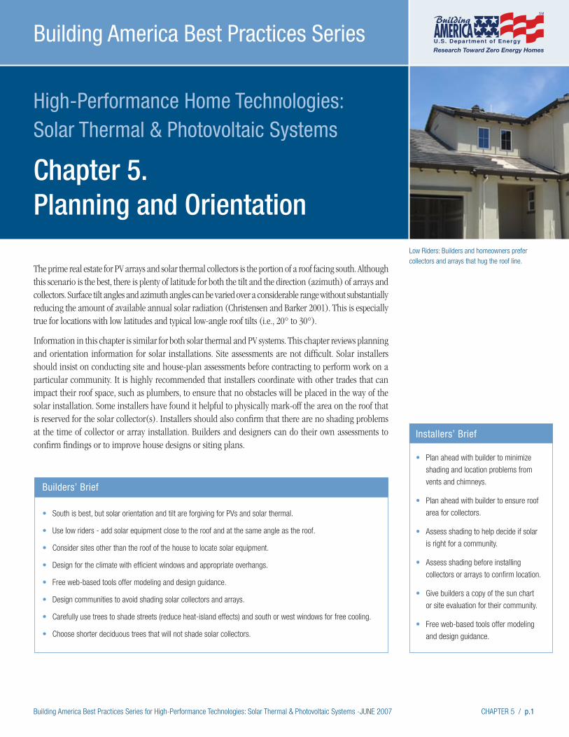
Building America Best Practices Series for High-Performance Technologies: Solar Thermal & Photovoltaic Systems -JUNE 2007 CHAPTER 5 / p.1
High-Performance Home Technologies: Solar Thermal & Photovoltaic Systems
Chapter 5. Planning and Orientation
Building America Best Practices Series
Low Riders: Builders and homeowners prefer collectors and arrays that hug the roof line.
The prime real estate for PV arrays and solar thermal collectors is the portion of a roof facing south. Although this scenario is the best, there is plenty of latitude for both the tilt and the direction (azimuth) of arrays and collectors. Surface tilt angles and azimuth angles can be varied over a considerable range without substantially reducing the amount of available annual solar radiation (Christensen and Barker 2001). This is especially true for locations with low latitudes and typical low-angle roof tilts (i.e., 20° to 30°).
Information in this chapter is similar for both solar thermal and PV systems. This chapter reviews planning and orientation information for solar installations. Site assessments are not difficult. Solar installers should insist on conducting site and house-plan assessments before contracting to perform work on a particular community. It is highly recommended that installers coordinate with other trades that can impact their roof space, such as plumbers, to ensure that no obstacles will be placed in the way of the solar installation. Some installers have found it helpful to physically mark-off the area on the roof that is reserved for the solar collector(s). Installers should also confirm that there are no shading problems at the time of collector or array installation. Builders and designers can do their own assessments to confirm findings or to improve house designs or siting plans.
Builders’ Brief
• South is best, but solar orientation and tilt are forgiving for PVs and solar thermal.
• Use low riders - add solar equipment close to the roof and at the same angle as the roof.
• Consider sites other than the roof of the house to locate solar equipment.
• Design for the climate with efficient windows and appropriate overhangs.
• Free web-based tools offer modeling and design guidance.
• Design communities to avoid shading solar collectors and arrays.
• Carefully use trees to shade streets (reduce heat-island effects) and south or west windows for free cooling.
• Choose shorter deciduous trees that will not shade solar collectors.
Installers’ Brief
• Plan ahead with builder to minimize
shading and location problems from
vents and chimneys.
• Plan ahead with builder to ensure roof
area for collectors.
• Assess shading to help decide if solar
is right for a community.
• Assess shading before installing
collectors or arrays to confirm location.
• Give builders a copy of the sun chart
or site evaluation for their community.
• Free web-based tools offer modeling
and design guidance.
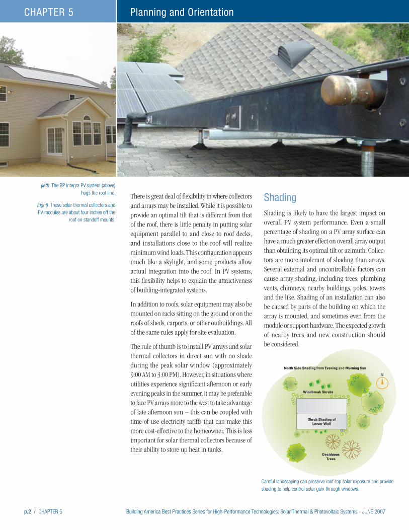
p.2 / CHAPTER 5 Building America Best Practices Series for High-Performance Technologies: Solar Thermal & Photovoltaic Systems - JUNE 2007
Planning and OrientationCHAPTER 5
There is great deal of flexibility in where collectors and arrays may be installed. While it is possible to provide an optimal tilt that is different from that of the roof, there is little penalty in putting solar equipment parallel to and close to roof decks, and installations close to the roof will realize minimum wind loads. This configuration appears much like a skylight, and some products allow actual integration into the roof. In PV systems, this flexibility helps to explain the attractiveness of building-integrated systems.
In addition to roofs, solar equipment may also be mounted on racks sitting on the ground or on the roofs of sheds, carports, or other outbuildings. All of the same rules apply for site evaluation.
The rule of thumb is to install PV arrays and solar thermal collectors in direct sun with no shade during the peak solar window (approximately 9:00 AM to 3:00 PM). However, in situations where utilities experience significant afternoon or early evening peaks in the summer, it may be preferable to face PV arrays more to the west to take advantage of late afternoon sun – this can be coupled with time-of-use electricity tariffs that can make this more cost-effective to the homeowner. This is less important for solar thermal collectors because of their ability to store up heat in tanks.
Shading Shading is likely to have the largest impact on overall PV system performance. Even a small percentage of shading on a PV array surface can have a much greater effect on overall array output than obtaining its optimal tilt or azimuth. Collec-tors are more intolerant of shading than arrays. Several external and uncontrollable factors can cause array shading, including trees, plumbing vents, chimneys, nearby buildings, poles, towers and the like. Shading of an installation can also be caused by parts of the building on which the array is mounted, and sometimes even from the module or support hardware. The expected growth of nearby trees and new construction should be considered.
(left) The BP Integra PV system (above) hugs the roof line.
(right) These solar thermal collectors and PV modules are about four inches off the
roof on standoff mounts.
N
Deciduous Trees
Shrub Shading ofLower Wall
Windbreak Shrubs
North Side Shading from Evening and Morning Sun
Careful landscaping can preserve roof-top solar exposure and provide shading to help control solar gain through windows.

Building America Best Practices Series for High-Performance Technologies: Solar Thermal & Photovoltaic Systems - JUNE 2007 CHAPTER 5 / p.3
Planning and Orientation CHAPTER 5
(left) This solar thermal system is ground mounted. Photo courtesy of Leif Juell, Alternative Power Enterprises, Inc.
(right top) To preserve a traditional appearance, Tindall Homes locates its PV systems away from the house on sheds. Photo courtesy of John Moyniham of Bald Eagle Solar.
(right bottom) This solar collector and PV array are subject to shading by a nearby structure. Photo courtesy of NREL.
A simple rule of thumb is that any potential shading structure should be twice as far away from the PV array as it is tall. In addition, a detailed evaluation
of the southern horizon can be used to predict shading issues arising from things that are not part of the home. Several devices are available for this analysis, and are discussed below. Shading should be evaluated as part of the design phase to ensure that a site is suitable for solar. Shading should
also be evaluated at the time of solar equipment installation to ensure the prime roof area is selected and that there are no shading issues that were not considered.
Site evaluations use sun charts or digital tools to assess how obstructions, such as trees, buildings, or chimneys, will fall between the installation and the sun at various times of the year. Sun charts are available at no cost from the University of Oregon on the web at http://solardata.uoregon.edu/SunChartProgram.html. A sample U. of O. sun chart is shown below. Solar thermal and PV installers should have equipment to simplify site evaluations. In short, the equipment provides a way to add sources of shading to the sun chart. Anywhere a potential obstruction crosses into the solar window, it blocks critical solar energy.
DD
HH
Any potential shading structure should be twice as far away from the PV array as it is tall (D = 2 * H))
The sun chart shows where the sun will be in the sky at a particular time of day each month.
Each of the blue lines represents the path of the sun during a particular month. Only half a year is needed, because the year is symmetrical. The red lines show the time of day.
Custom sun charts are available on the web from the University of Oregon at http://solardat.uoregon.edu/download/temp/50651026.pdf. The green area superimposed on the chart shows the annual solar window in which shading would be especially detrimental. The summer solstice is the longest day of the year. The winter solstice is the shortest.
Sun Charts
SUMMER SOLSTICE
WINTER SOLSTICE
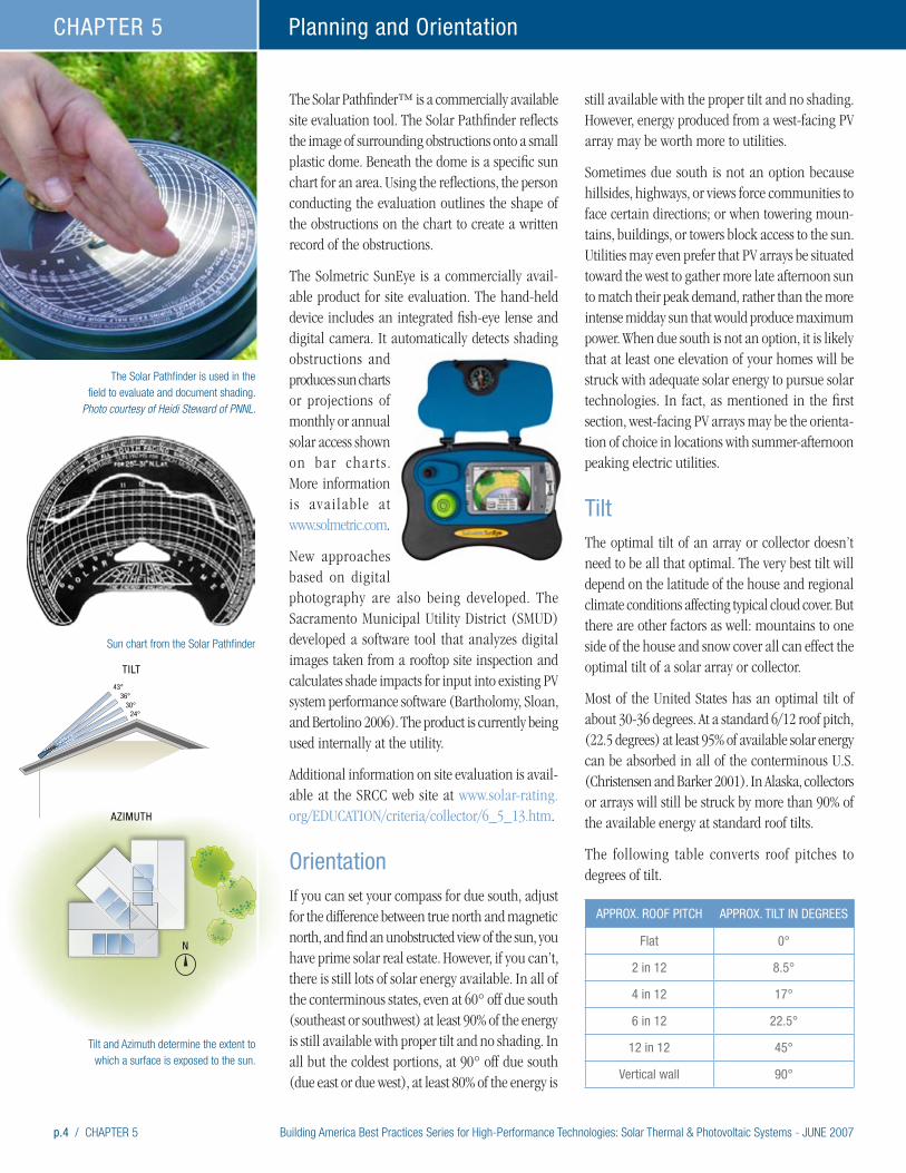
p.4 / CHAPTER 5 Building America Best Practices Series for High-Performance Technologies: Solar Thermal & Photovoltaic Systems - JUNE 2007
Planning and OrientationCHAPTER 5
The Solar Pathfinder™ is a commercially available site evaluation tool. The Solar Pathfinder reflects the image of surrounding obstructions onto a small plastic dome. Beneath the dome is a specific sun chart for an area. Using the reflections, the person conducting the evaluation outlines the shape of the obstructions on the chart to create a written record of the obstructions.
The Solmetric SunEye is a commercially avail-able product for site evaluation. The hand-held device includes an integrated fish-eye lense and digital camera. It automatically detects shading obstructions and produces sun charts or projections of monthly or annual solar access shown on bar char ts . More information is available at www.solmetric.com.
New approaches based on digital photography are also being developed. The Sacramento Municipal Utility District (SMUD) developed a software tool that analyzes digital images taken from a rooftop site inspection and calculates shade impacts for input into existing PV system performance software (Bartholomy, Sloan, and Bertolino 2006). The product is currently being used internally at the utility.
Additional information on site evaluation is avail-able at the SRCC web site at www.solar-rating.org/EDUCATION/criteria/collector/6_5_13.htm.
OrientationIf you can set your compass for due south, adjust for the difference between true north and magnetic north, and find an unobstructed view of the sun, you have prime solar real estate. However, if you can’t, there is still lots of solar energy available. In all of the conterminous states, even at 60° off due south (southeast or southwest) at least 90% of the energy is still available with proper tilt and no shading. In all but the coldest portions, at 90° off due south (due east or due west), at least 80% of the energy is
still available with the proper tilt and no shading. However, energy produced from a west-facing PV array may be worth more to utilities.
Sometimes due south is not an option because hillsides, highways, or views force communities to face certain directions; or when towering moun-tains, buildings, or towers block access to the sun. Utilities may even prefer that PV arrays be situated toward the west to gather more late afternoon sun to match their peak demand, rather than the more intense midday sun that would produce maximum power. When due south is not an option, it is likely that at least one elevation of your homes will be struck with adequate solar energy to pursue solar technologies. In fact, as mentioned in the first section, west-facing PV arrays may be the orienta-tion of choice in locations with summer-afternoon peaking electric utilities.
TiltThe optimal tilt of an array or collector doesn’t need to be all that optimal. The very best tilt will depend on the latitude of the house and regional climate conditions affecting typical cloud cover. But there are other factors as well: mountains to one side of the house and snow cover all can effect the optimal tilt of a solar array or collector.
Most of the United States has an optimal tilt of about 30-36 degrees. At a standard 6/12 roof pitch, (22.5 degrees) at least 95% of available solar energy can be absorbed in all of the conterminous U.S. (Christensen and Barker 2001). In Alaska, collectors or arrays will still be struck by more than 90% of the available energy at standard roof tilts.
The following table converts roof pitches to degrees of tilt.
APPROx. ROOF PITCH APPROx. TILT IN DEGREES
Flat 0°
2 in 12 8.5°
4 in 12 17°
6 in 12 22.5°
12 in 12 45°
Vertical wall 90°
The Solar Pathfinder is used in the field to evaluate and document shading.
Photo courtesy of Heidi Steward of PNNL.
43°
AZIMUTH
TILT
36°30°
24°
N
Sun chart from the Solar Pathfinder
Tilt and Azimuth determine the extent to which a surface is exposed to the sun.
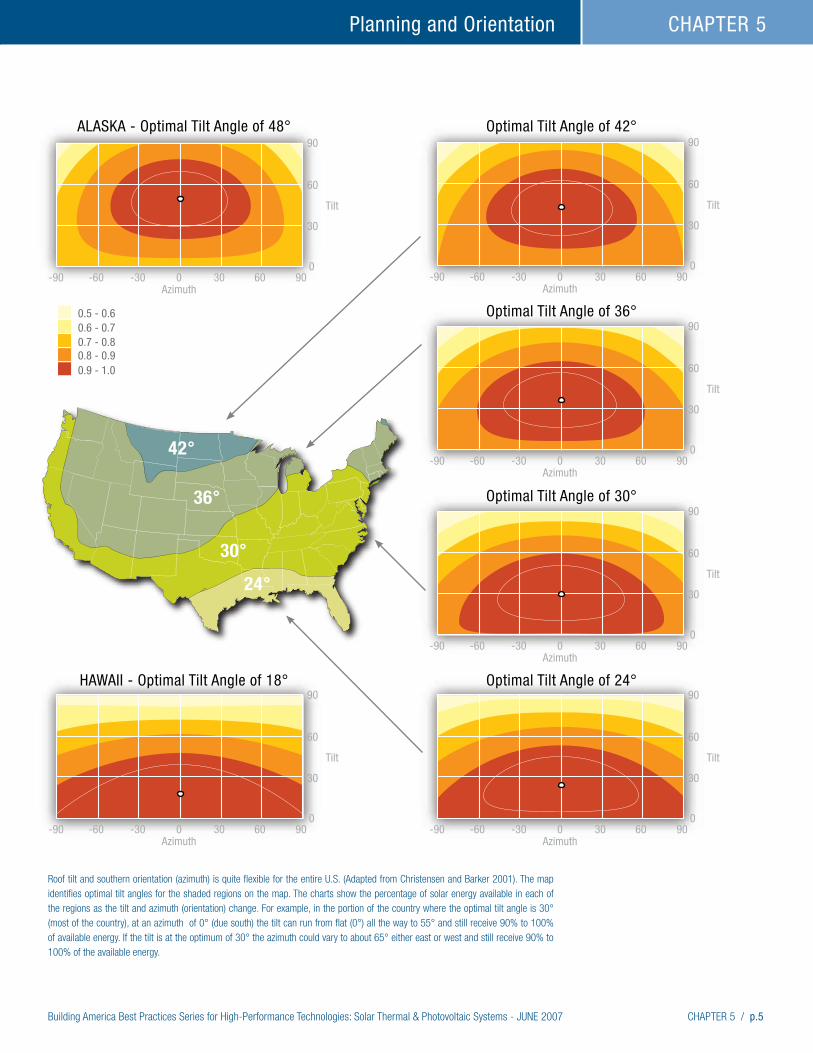
Building America Best Practices Series for High-Performance Technologies: Solar Thermal & Photovoltaic Systems - JUNE 2007 CHAPTER 5 / p.5
Planning and Orientation CHAPTER 5
Roof tilt and southern orientation (azimuth) is quite flexible for the entire U.S. (Adapted from Christensen and Barker 2001). The map identifies optimal tilt angles for the shaded regions on the map. The charts show the percentage of solar energy available in each of the regions as the tilt and azimuth (orientation) change. For example, in the portion of the country where the optimal tilt angle is 30° (most of the country), at an azimuth of 0° (due south) the tilt can run from flat (0°) all the way to 55° and still receive 90% to 100% of available energy. If the tilt is at the optimum of 30° the azimuth could vary to about 65° either east or west and still receive 90% to 100% of the available energy.
-90 -60 -30 0Azimuth
Optimal Tilt Angle of 42°
Optimal Tilt Angle of 36°
Optimal Tilt Angle of 30°
Optimal Tilt Angle of 24°
ALASKA - Optimal Tilt Angle of 48°
HAWAII - Optimal Tilt Angle of 18°
Tilt
030
30
60
90
60 90
-90 -60 -30 0Azimuth
Tilt
030
30
60
90
60 90
-90 -60 -30 0Azimuth
Tilt
030
30
60
90
60 90
-90 -60 -30 0Azimuth
Tilt
030
30
60
90
60 90-90 -60 -30 0Azimuth
Tilt
030
30
60
90
0.5 - 0.60.6 - 0.70.7 - 0.80.8 - 0.90.9 - 1.0
60 90
-90 -60 -30 0Azimuth
Tilt
030
30
60
90
60 90
42°
36°
30°
24°
p.6 / CHAPTER 5 Building America Best Practices Series for High-Performance Technologies: Solar Thermal & Photovoltaic Systems - JUNE 2007
Planning and OrientationCHAPTER 5
Modeling Performance and System SizingPart of the site assessment, design, and decision making may include modeling solar performance. This modeling may or may not include economic analysis. The tools listed here are free web-based models and estimators.
The RETScreen® International Solar Water Heating Model can be used world-wide to evaluate the energy production, life-cycle costs, and greenhouse gas emissions reduction for three applications: domestic hot water, industrial process heat and swimming pools (indoor and outdoor), ranging in size from small residential systems to large-scale commercial, institutional and industrial systems. The model contains a database of essentially all commercially available solar thermal collectors. The model is free, but registration is required. The model can be accessed at www.retscreen.net. This site also includes models for evaluating PV systems and other renewable and energy-efficient technologies.
The California Energy Commission maintains an extensive website with much information about PV systems. One feature is a list of modules that qualify for that State’s rebate program. This list is available at www.consumerenergycenter.org/cgi-bin/eligible_pvmodules.cgi. There is also a list of qualifying inverters at www.consumerenergycenter.org/erprebate/documents/2002_tax_credit/2003-03-03_APPR_PV_LIST.PDF#search=%22photovoltaic%20model%22. The site also includes a feature to help find California installers at www.consumeren-ergycenter.org/erprebate/database/index.html.
A PV system sizing model called the Clean Power Estimator is available at www.consumerenergycen-ter.org/pv4newbuildings/schematicdesign.html.
PVWATTS is a free model available from NREL that calculates electrical energy produced from a grid-connected PV system. Access to the model is available at http://rredc.nrel.gov/solar/codes_algs/PVWATTS/.
Another web-based resource is Find Solar. This site has energy calculators for photovoltaic and solar domestic hot water and pool/spa heating. The site
is sponsored by the American Solar Energy Society, Solar Electric Power Association, Energy Matter LLC, and the U.S. DOE. A PV solar estimator meant to help roughly identify price, savings, and system size can be found at www.findsolar.com/index.php?page=rightforme.
For a listing of free and available-for-purchase energy models, including solar design tools, see DOE’s Building Technology Program web site at www.eere.energy.gov/buildings/tools_directory.
Site PlanningBetter understanding of available solar energy and improvements in window technologies have done much to increase flexibility in site planning while still giving consumers the value of solar energy. Still, site planning should take advantage of southern window and roof exposures. Lay out lots, trees, houses, and community buildings being careful to avoid shading neighboring roofs. Orient community and private pools to allow for solar water heating and include the solar systems as part of initial construction. Allow enough roof area facing south for both solar thermal and PV systems. The CEC suggests that the rough sizing requirements for PV are about 100 sq. ft. for each kilowatt of system capacity for crystalline technologies and 175 sq. ft. for each kilowatt of thin film PV products. Solar thermal systems will likely require one or two collectors requiring about 32 sq. ft. each.
WindowsPositioning buildings to get the maximum amount of sun means selecting windows and overhangs to help manage the solar energy. Thoughtful design for your climate and site will increase value for consumers by making the sun an ally. Windows should be selected to manage the quantity of solar heat gain allowed into the house. In cold climates, it may make sense to use windows with a high solar heat gain coefficient. These windows will allow solar heat gain to help heat the house in winter where summer heat gain is not important. These windows are also valuable for winter heating in
Building America Best Practices Series for High-Performance Technologies: Solar Thermal & Photovoltaic Systems - JUNE 2007 CHAPTER 5 / p.7
Planning and Orientation CHAPTER 5
mixed climates where they can be shaded by well designed overhangs during summer months.
Where sun is ample and cooling dominates utility bills, windows with low solar heat gain coefficients and high visible light transmittance will help to block both infrared and ultraviolet light while allowing visible light into the spaces. These windows will protect furniture, carpeting, and other surfaces from fading and will greatly increase occupant comfort.
The Efficient Windows Collaborative operates a web site that can help designers and consumers
choose windows. The web site includes a tool that allows users to analyze energy costs and savings for windows with different ratings. Visit the web site at www.efficientwindows.org/index.cfm.
The Web site also has fact sheets with comparisons for each state. These fact sheets could make effective marketing tools. Also described on the web site is a book entitled Residential Windows: A Guide to New Technologies and Energy Performance (Carmody et al. 2000), which offers homeowners, architects, designers, and builders a fascinating look at the state of the art in window technology.
Cool Neighborhoods Have Shade
Tree preservation brings many benefits, one of which is increased salability. Native trees are most beneficial to the environment. The NAHB reports in its survey of buyers, What 21st Century Home Buyers Want, that over 80% of respondents in the West rated trees as essential or desirable (2002b, page 61). In 1992, the Florida Solar Energy Center (FSEC) estimated that a treed lot in Florida may increase the value of a home by as much as 20%. American Forests and the NAHB (1995) found that mature trees may add from $3,000 to $15,000 to the value of a residential lot.
Trees also bring value by providing shade. It is far better to prevent solar energy from reaching a house with a heavy air conditioning load than to attempt to manage it once it enters, with the additional consideration of solar heating in the winter. Shade trees can block summer sunlight before it strikes windows, walls, and roofs, dissipating absorbed heat to the air where it can be carried away by the breeze. However, when photovoltaic and/or water heating systems will be used, trees must be placed not to shade these systems. This dual-function can often be achieved by carefully selecting the variety of tree for height and width as well as being deciduous.
Truly cool neighborhoods have trees. A study in Florida has shown that a subdivision with mature trees had cooler outside air with less wind velocity than a nearby development without trees (Sonne and Viera. 2000). The development with a tree canopy had peak afternoon temperatures during July that were 1.1°F to 3.1°F ( ± 0.7°F) cooler than the site without trees. The total effect of shading, lower summer air temperature, and reduced wind speed can reduce cooling costs by 5% to 10% (McPherson et al. 1994).
For reducing cooling requirements, trees are most effective when carefully located to cast shade on the roof, windows, walls, and air conditioners, and when located on the side of the home receiving the most solar exposure. Shade to the southwest and west is especially important for blocking peak solar gain in the summer in late afternoon. Depending on the species, trees more than 35 feet from the structure are probably too far away for shade. Plants too close to air conditioners or heat pumps can plug coils. Be careful not to shade solar equipment. Energy-efficient windows are comfortable to
sit near and provide protection for furniture and window treatments.
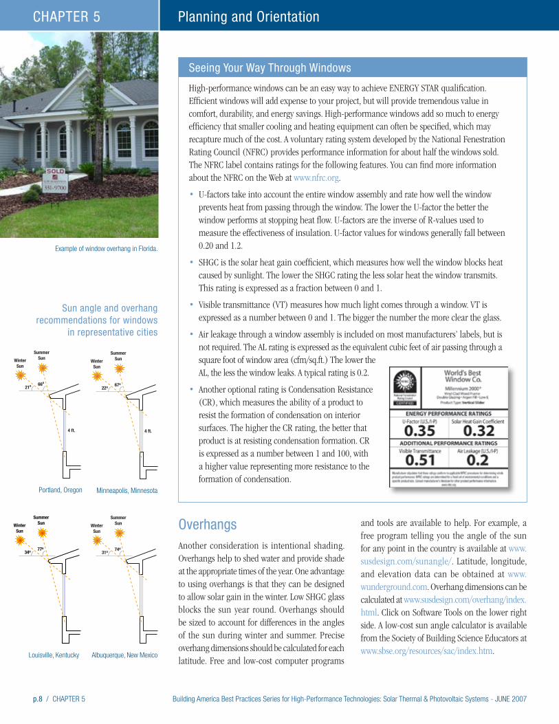
p.8 / CHAPTER 5 Building America Best Practices Series for High-Performance Technologies: Solar Thermal & Photovoltaic Systems - JUNE 2007
Planning and OrientationCHAPTER 5
Example of window overhang in Florida.
OverhangsAnother consideration is intentional shading. Overhangs help to shed water and provide shade at the appropriate times of the year. One advantage to using overhangs is that they can be designed to allow solar gain in the winter. Low SHGC glass blocks the sun year round. Overhangs should be sized to account for differences in the angles of the sun during winter and summer. Precise overhang dimensions should be calculated for each latitude. Free and low-cost computer programs
and tools are available to help. For example, a free program telling you the angle of the sun for any point in the country is available at www.susdesign.com/sunangle/. Latitude, longitude, and elevation data can be obtained at www.wunderground.com. Overhang dimensions can be calculated at www.susdesign.com/overhang/index.html. Click on Software Tools on the lower right side. A low-cost sun angle calculator is available from the Society of Building Science Educators at www.sbse.org/resources/sac/index.htm.
Seeing Your Way Through Windows
High-performance windows can be an easy way to achieve ENERGY STAR qualification. Efficient windows will add expense to your project, but will provide tremendous value in comfort, durability, and energy savings. High-performance windows add so much to energy efficiency that smaller cooling and heating equipment can often be specified, which may recapture much of the cost. A voluntary rating system developed by the National Fenestration Rating Council (NFRC) provides performance information for about half the windows sold. The NFRC label contains ratings for the following features. You can find more information about the NFRC on the Web at www.nfrc.org.
• U-factors take into account the entire window assembly and rate how well the window prevents heat from passing through the window. The lower the U-factor the better the window performs at stopping heat flow. U-factors are the inverse of R-values used to measure the effectiveness of insulation. U-factor values for windows generally fall between 0.20 and 1.2.
• SHGC is the solar heat gain coefficient, which measures how well the window blocks heat caused by sunlight. The lower the SHGC rating the less solar heat the window transmits. This rating is expressed as a fraction between 0 and 1.
• Visible transmittance (VT) measures how much light comes through a window. VT is expressed as a number between 0 and 1. The bigger the number the more clear the glass.
• Air leakage through a window assembly is included on most manufacturers’ labels, but is not required. The AL rating is expressed as the equivalent cubic feet of air passing through a square foot of window area (cfm/sq.ft.) The lower the AL, the less the window leaks. A typical rating is 0.2.
• Another optional rating is Condensation Resistance (CR), which measures the ability of a product to resist the formation of condensation on interior surfaces. The higher the CR rating, the better that product is at resisting condensation formation. CR is expressed as a number between 1 and 100, with a higher value representing more resistance to the formation of condensation.
WinterSun
SummerSun
21o
4 ft.
66o
Sun angle and overhang recommendations for windows
in representative cities
WinterSun
SummerSun
22o
4 ft.
67o
WinterSun
SummerSun
34o 77o
WinterSun
SummerSun
31o 74o
Portland, Oregon Minneapolis, Minnesota
Louisville, Kentucky Albuquerque, New Mexico
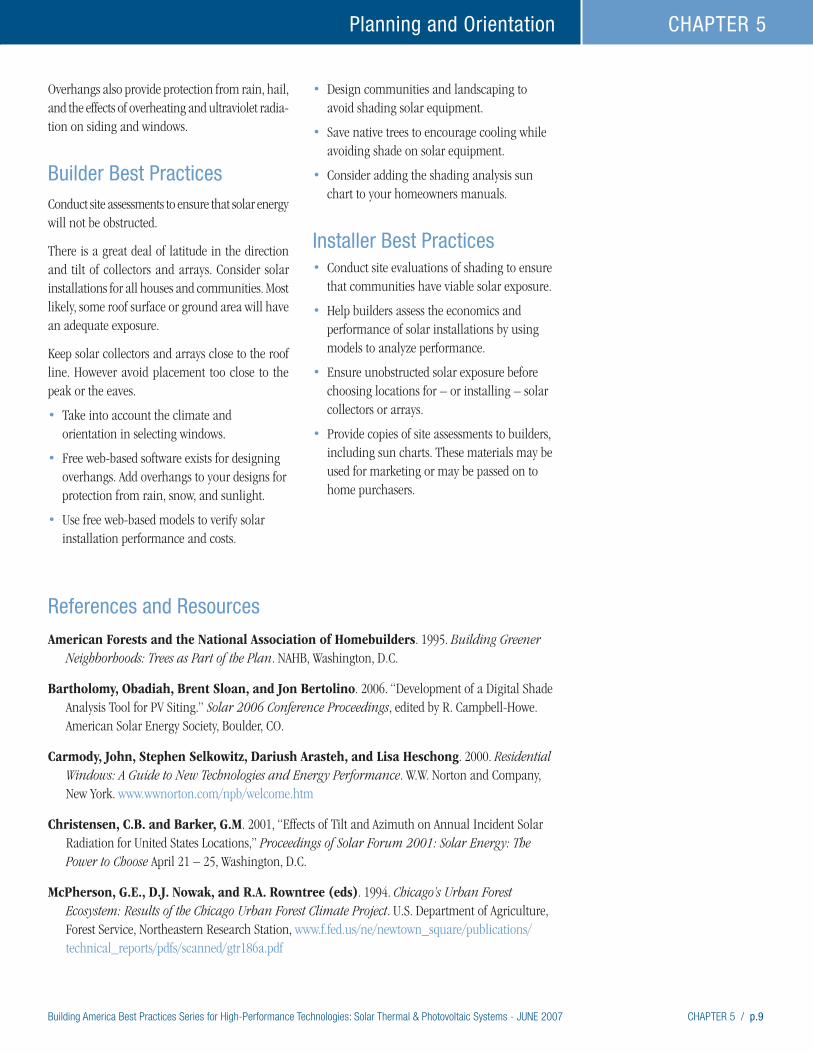
Building America Best Practices Series for High-Performance Technologies: Solar Thermal & Photovoltaic Systems - JUNE 2007 CHAPTER 5 / p.9
Planning and Orientation CHAPTER 5
Overhangs also provide protection from rain, hail, and the effects of overheating and ultraviolet radia-tion on siding and windows.
Builder Best PracticesConduct site assessments to ensure that solar energy will not be obstructed.
There is a great deal of latitude in the direction and tilt of collectors and arrays. Consider solar installations for all houses and communities. Most likely, some roof surface or ground area will have an adequate exposure.
Keep solar collectors and arrays close to the roof line. However avoid placement too close to the peak or the eaves.
• Take into account the climate and orientation in selecting windows.
• Free web-based software exists for designing overhangs. Add overhangs to your designs for protection from rain, snow, and sunlight.
• Use free web-based models to verify solar installation performance and costs.
• Design communities and landscaping to avoid shading solar equipment.
• Save native trees to encourage cooling while avoiding shade on solar equipment.
• Consider adding the shading analysis sun chart to your homeowners manuals.
Installer Best Practices• Conduct site evaluations of shading to ensure
that communities have viable solar exposure.
• Help builders assess the economics and performance of solar installations by using models to analyze performance.
• Ensure unobstructed solar exposure before choosing locations for – or installing – solar collectors or arrays.
• Provide copies of site assessments to builders, including sun charts. These materials may be used for marketing or may be passed on to home purchasers.
References and Resources
American Forests and the National Association of Homebuilders. 1995. Building Greener Neighborhoods: Trees as Part of the Plan. NAHB, Washington, D.C.
Bartholomy, Obadiah, Brent Sloan, and Jon Bertolino. 2006. “Development of a Digital Shade Analysis Tool for PV Siting.” Solar 2006 Conference Proceedings, edited by R. Campbell-Howe. American Solar Energy Society, Boulder, CO.
Carmody, John, Stephen Selkowitz, Dariush Arasteh, and Lisa Heschong. 2000. Residential Windows: A Guide to New Technologies and Energy Performance. W.W. Norton and Company, New York. www.wwnorton.com/npb/welcome.htm
Christensen, C.B. and Barker, G.M. 2001, “Effects of Tilt and Azimuth on Annual Incident Solar Radiation for United States Locations,” Proceedings of Solar Forum 2001: Solar Energy: The Power to Choose April 21 – 25, Washington, D.C.
McPherson, G.E., D.J. Nowak, and R.A. Rowntree (eds). 1994. Chicago’s Urban Forest Ecosystem: Results of the Chicago Urban Forest Climate Project. U.S. Department of Agriculture, Forest Service, Northeastern Research Station, www.f.fed.us/ne/newtown_square/publications/technical_reports/pdfs/scanned/gtr186a.pdf
p.10 / CHAPTER 5 Building America Best Practices Series for High-Performance Technologies: Solar Thermal & Photovoltaic Systems - JUNE 2007
Planning and OrientationCHAPTER 5
National Association of Home Builders. 2002b. What 21st Century Home Buyers Want: A Survey of Customer Preferences. NAHB, Washington, D.C. www.BuilderBooks.com
Sonne, J.K. and R.K. Viera. 2000. “Cool Neighborhoods: The Measurement of Small Scale Heat Islands.” Proceedings of the 2000 Summer Study on Energy Efficiency in Buildings, American Council for an Energy-Efficient Economy, Washington, DC. www.fsec.ucf.edu/bldg/pubs/pf363/index.htm
Viera, R.K., K.G. Sheinkopf, and J.K. Sonne. 1992. Energy-Efficient Florida Home Building, third printing. Florida Solar Energy Center, FSEC-GP-33-88, Cocoa Beach, FL.
SRCC site evaluation information: www.solar-rating.org/EDUCATION/criteria/collector/6_5_13.htm
Solarmodeling software: www.retscreen.net/
California Energy Commission list of qualifying PV modules: www.consumerenergycenter.org/cgi-bin/eligible_pvmodules.cgi
California Energy Commission list of qualifying inverters: www.consumerenergycenter.org/erprebate/documents/2002_tax_credit/ 2003-03-03_APPR_PV_LIST.PDF#search=%22photovoltaic%20model%22
California Energy Commission list of installers: www.consumerenergycenter.org/erprebate/database/index.html
California Energy Commission PV system sizing model called the Clean Power Estimator: www.consumerenergycenter.org/pv4newbuildings/schematicdesign.html
PV solar estimator meant to help roughly identify price, savings, and system size can be found at: www.findsolar.com/index.php?page=rightforme
DOE’s Building Technology Program. www.eere.energy.gov/buildings/tools_directory
The Efficient Windows Collaborative. www.efficientwindows.org/index.cfm
A free program telling you the angle of the sun for any point in the country. www.susdesign.com/sunangle/
Sun charts are available at no cost from the University of Oregon on the web at: http://solardata.uoregon.edu/SunChartProgram.html
Information on the Solmetric SunEye is available at: www.solmetric.com
NREL’s PVWATTS model for grid-connected PV systems is available at: http://rredc.nrel.gov/solar/codes_algs/PVWATTS/

Building America Best Practices Series for High-Performance Technologies: Solar Thermal & Photovoltaic Systems - JUNE 2007 CHAPTER 6 / p.1
High-Performance Home Technologies: Solar Thermal & Photovoltaic Systems
Chapter 6. Rack-Mounted Systems
Building America Best Practices Series
Solar collectors mounted on a standing seam roof. Photo courtesy of Leif Juell, Alternative Power Enterprises, Inc.Roof Penetrations and Mounts
Atop many automobiles are roof-top rack systems that carry everything from kayaks to bicycles. These systems are pre-engineered to carry these loads at highway speeds and their modular pieces are easily installed. Think of the hardware for mounting solar collectors and arrays as roof racks for houses. The best systems are pre-engineered to carry loads and use matched hardware.
Of course roof-top mounts for solar equipment must also protect the house from water intrusion. A recent study of one of the first ZEH communities that incorporated both solar thermal and PV technolo-gies, reports that absolutely no problems have been reported related to water leakage (Nelson 2005). Flashing systems are described in this chapter.
Building integrated systems tend to either attach directly to the roof deck and/or use proprietary mounting systems. Three of these types of systems are described in Chapter 4: Photovoltaic Power Generation, and a roof deck-mounted approach for ICS is described in Chapter 3: Solar-Thermal Water Heating.
Two references are important to acknowledge as resources for this chapter and for designers. The first is a 2005 evaluation of roof-mounting approaches for solar thermal systems prepared by the Davis Energy Group, titled Zero Energy Homes Solar Thermal Collector Mounting Evaluation.
Another good reference for flashing all roof systems is the National Roofing Contractors Association (NRCA 2006) guidance document, entitled: The NRCA Roofing and Waterproofing Manual, Fifth Edition. The document is available online at www.nrca.net.
Structural LoadsThere are two structural concerns, dead load, the weight of the systems bearing on the roof, and live loads, the intermittent loads created by wind, snow, and maintenance people. Collectors should never be supported by roof sheathing between structural members. This is particularly important for ICS collectors, because they are heavy when full of water, although problems have been rare. Over 300 ICS systems were installed on low income housing during a Florida program and no structural changes had to be made to any of these homes (Harrison 2006). Before installation, installers did make sure that the roof was in good condition, with good trusses, and no sagging.
Nonetheless, the project structural engineer or truss designer should be involved early in the design process. Even if not needed to accommodate the load, additional framing may be added as a convenience for easier solar installations even if structural loads are within limits. The BP Integra system described later in this chapter used this approach. If modifications are needed, they should
Builders’ & Installers’ Brief
• Roof top mounts can place solar
thermal and PV systems very close to
the roof surface.
• If needed, such as on a flat roof,
mounts can also place solar systems
at optimal angles.
• Ensure systems are engineered for
dead loads and wind uplift.
• Install standoff mounts before roofing
is installed to allow for proper flashing
and sealing.
• If house roofs are not available, mount
solar systems on outbuildings or
ground mounts.
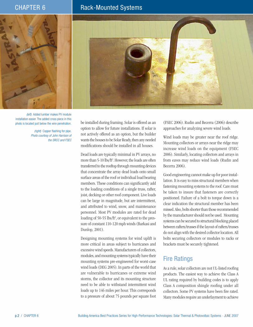
p.2 / CHAPTER 6 Building America Best Practices Series for High-Performance Technologies: Solar Thermal & Photovoltaic Systems - JUNE 2007
Rack-Mounted SystemsCHAPTER 6
be installed during framing. Solar is offered as an option to allow for future installations. If solar is not actively offered as an option, but the builder wants the houses to be Solar Ready, then any needed modifications should be installed in all houses.
Dead loads are typically minimal in PV arrays, no more than 5-10 lbs/ft2. However, the loads are often transferred to the rooftop through mounting devices that concentrate the array dead loads onto small surface areas of the roof or individual load bearing members. These conditions can significantly add to the loading conditions of a single truss, rafter, joist, decking or other roof component. Live loads can be large in magnitude, but are intermittent, and attributed to wind, snow, and maintenance personnel. Most PV modules are rated for dead loading of 50-55 lbs/ft2, or equivalent to the pres-sure of constant 110-120 mph winds (Barkasi and Dunlop, 2001).
Designing mounting systems for wind uplift is more critical in areas subject to hurricanes and excessive wind speeds. Manufacturers of collectors, modules, and mounting systems typically have their mounting systems pre-engineered for worst-case wind loads (DEG 2005). In parts of the world that are vulnerable to hurricanes or extreme wind storms, the collector and its mounting structure need to be able to withstand intermittent wind loads up to 146 miles per hour. This corresponds to a pressure of about 75 pounds per square foot
(FSEC 2006). Rudin and Becerra (2006) describe approaches for analyzing severe wind loads.
Wind loads may be greater near the roof ridge. Mounting collectors or arrays near the ridge may increase wind loads on the equipment (FSEC 2006). Similarly, locating collectors and arrays in from eaves may reduce wind loads (Rudin and Becerra 2006).
Good engineering cannot make up for poor instal-lation. It is easy to miss structural members when fastening mounting systems to the roof. Care must be taken to insure that fasteners are correctly positioned. Failure of a bolt to torque down is a clear indication the structural member has been missed. Also, bolts shorter than those recommended by the manufacturer should not be used. Mounting systems can be secured to structural blocking placed between rafters/trusses if the layout of rafters/trusses do not align with the desired collector location. All bolts securing collectors or modules to racks or brackets must be securely tightened.
Fire RatingsAs a rule, solar collectors are not UL-listed roofing products. The easiest way to achieve the Class A UL rating required by building codes is to apply Class A composition shingle roofing under all collectors. Some PV systems have been fire rated. Many modules require an underlayment to achieve
(left) Added lumber makes PV module installation easier. The added cross piece in this photo is located just below the wire penetration.
(right) Copper flashing for pipe. Photo courtesy of John Harrison of
the SRCC and FSEC
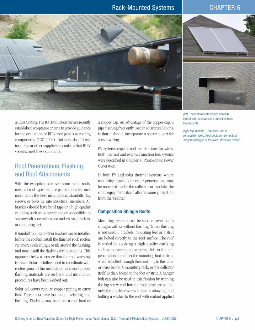
Building America Best Practices Series for High-Performance Technologies: Solar Thermal & Photovoltaic Systems - JUNE 2007 CHAPTER 6 / p.3
Rack-Mounted Systems CHAPTER 6
(left) Standoff mounts located beneath the collector receive some protection from the elements.
(right top, bottom) L brackets used on composition roofs. Roof photo compliments of Joseph Wiehagen of the NAHB Research Center.
a Class A rating. The ICC Evaluation Service recently established acceptance criteria to provide guidance for the evaluation of BIPV roof panels as roofing components (ICC 2006). Builders should ask installers or other suppliers to confirm that BIPV systems meet these standards.
Roof Penetrations, Flashing, and Roof AttachmentsWith the exception of raised-seam metal roofs, most all roof types require penetrations for rack mounts. In the best installations, standoffs, lag screws, or bolts tie into structural members. All brackets should have butyl tape or a high-quality caulking such as polyurethane or polysulfide, to seal any bolt penetrations and under struts, brackets, or mounting feet.
If standoff mounts or other brackets can be installed before the roofers install the finished roof, roofers can more easily shingle or tile around the flashing, and may install the flashing for the mounts. This approach helps to ensure that the roof warranty is intact. Solar installers need to coordinate with roofers prior to the installation to ensure proper flashing materials are on hand and installation procedures have been worked out.
Solar collectors require copper piping to carry fluid. Pipes must have insulation, jacketing, and flashing. Flashing may be either a roof boot or
a copper cap. An advantage of the copper cap, a pipe flashing frequently used in solar installations, is that it should incorporate a separate port for sensor wiring.
PV systems require roof penetrations for wires. Both internal and external junction box systems were described in Chapter 4: Photovoltaic Power Generation.
In both PV and solar thermal systems, where mounting brackets or other penetrations may be mounted under the collector or module, the solar equipment itself affords some protection from the weather.
Composition Shingle Roofs
Mounting systems can be secured over comp shingles with or without flashing. Where flashing is not used, L brackets, mounting feet or a strut are bolted directly to the roof surface. The roof is sealed by applying a high-quality caulking such as polyurethane or polysulfide to the bolt penetration and under the mounting foot or strut, which is bolted through the sheathing to the rafter or truss below. A mounting rack, or the collector itself, is then bolted to the foot or strut. A hanger bolt can also be used in this fashion by running the lag screw end into the roof structure so that only the machine screw thread is showing, and bolting a washer to the roof with sealant applied
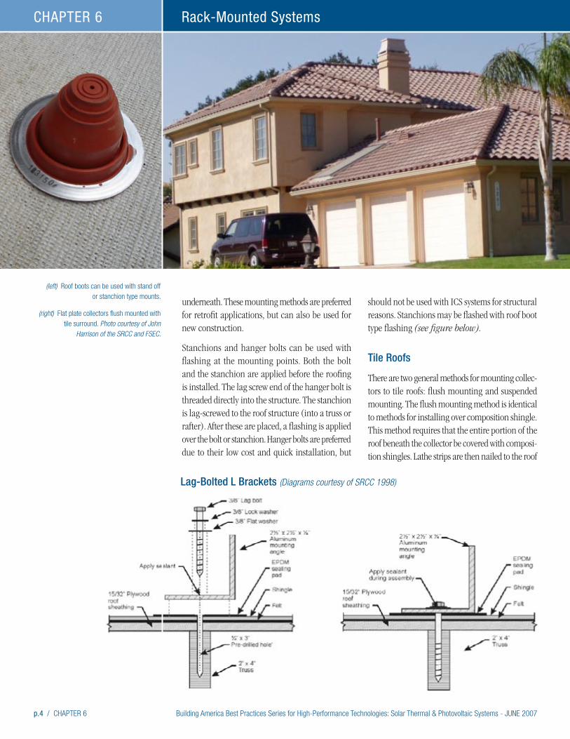
p.4 / CHAPTER 6 Building America Best Practices Series for High-Performance Technologies: Solar Thermal & Photovoltaic Systems - JUNE 2007
Rack-Mounted SystemsCHAPTER 6
underneath. These mounting methods are preferred for retrofit applications, but can also be used for new construction.
Stanchions and hanger bolts can be used with flashing at the mounting points. Both the bolt and the stanchion are applied before the roofing is installed. The lag screw end of the hanger bolt is threaded directly into the structure. The stanchion is lag-screwed to the roof structure (into a truss or rafter). After these are placed, a flashing is applied over the bolt or stanchion. Hanger bolts are preferred due to their low cost and quick installation, but
should not be used with ICS systems for structural reasons. Stanchions may be flashed with roof boot type flashing (see figure below).
Tile Roofs
There are two general methods for mounting collec-tors to tile roofs: flush mounting and suspended mounting. The flush mounting method is identical to methods for installing over composition shingle. This method requires that the entire portion of the roof beneath the collector be covered with composi-tion shingles. Lathe strips are then nailed to the roof
(left) Roof boots can be used with stand off or stanchion type mounts.
(right) Flat plate collectors flush mounted with tile surround. Photo courtesy of John
Harrison of the SRCC and FSEC.
Lag-Bolted L Brackets (Diagrams courtesy of SRCC 1998)
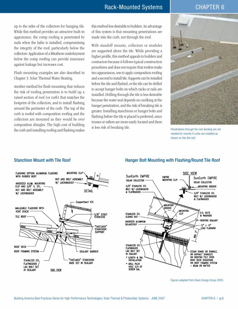
Building America Best Practices Series for High-Performance Technologies: Solar Thermal & Photovoltaic Systems - JUNE 2007 CHAPTER 6 / p.5
Rack-Mounted Systems CHAPTER 6
Stanchion Mount with Tile Roof
up to the sides of the collectors for hanging tile. While this method provides an attractive built-in appearance, the comp roofing is penetrated by nails when the lathe is installed, compromising the integrity of the roof, particularly below the collectors. Application of a Bituthene underlayment below the comp roofing can provide insurance against leakage but increases cost.
Flush mounting examples are also described in Chapter 3: Solar Thermal Water Heating.
Another method for flush mounting that reduces the risk of roofing penetration is to build up a raised section of roof (or curb) that matches the footprint of the collectors, and to install flashing around the perimeter of the curb. The top of the curb is roofed with composition roofing and the collectors are mounted as they would be over composition shingles. The high cost of building the curb and installing roofing and flashing makes
this method less desirable to builders. An advantage of this system is that mounting penetrations are made into the curb, not through the roof.
With standoff mounts, collectors or modules are supported above the tile. While providing a higher profile, this method appeals to builders and contractors because it follows typical construction procedures and does not require that roofers make two appearances, one to apply composition roofing and a second to install tile. Supports can be installed before the tile and flashed, or the tile can be drilled to accept hanger bolts on which racks or rails are installed. Drilling through the tile is less desirable because the water seal depends on caulking at the hanger penetration, and the risk of breaking tile is greater. Installing stanchions or hanger bolts and flashing before the tile is placed is preferred, since trusses or rafters are more easily located and there is less risk of breaking tile. Penetrations through the roof decking are not
needed for mounts if curbs are installed as shown on this flat roof.
Figures adapted from Davis Energy Group 2005.
Hanger Bolt Mounting with Flashing/Round Tile Roof
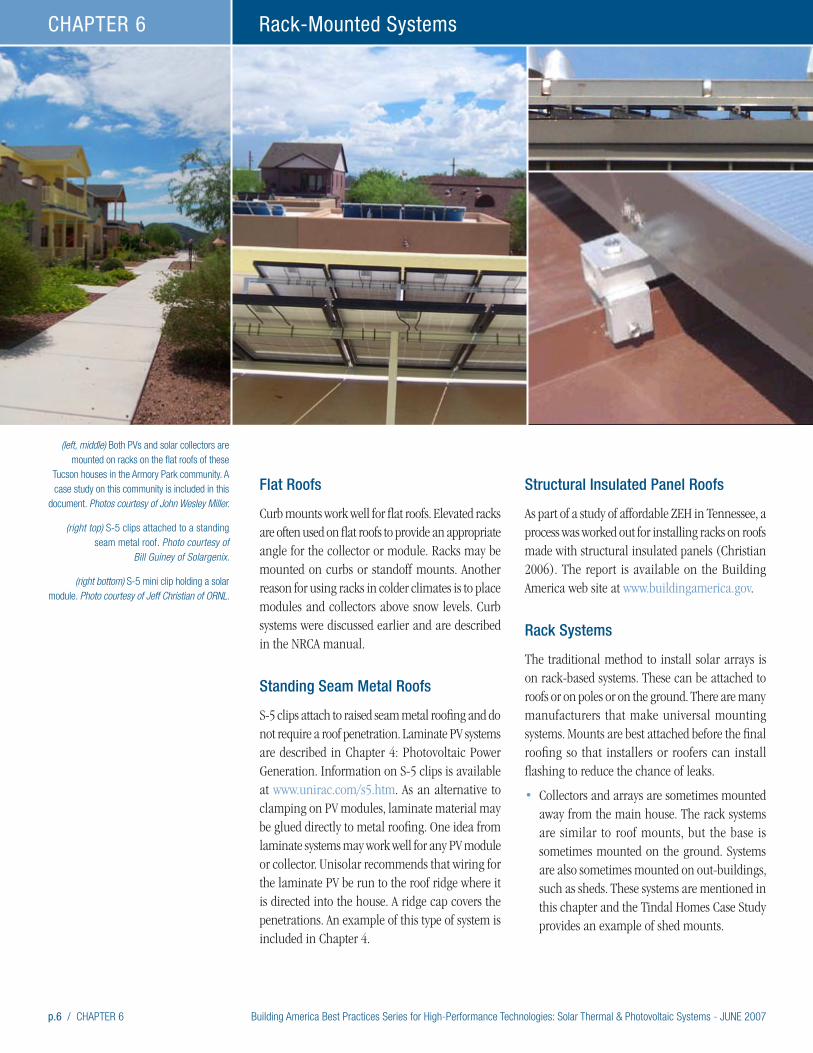
p.6 / CHAPTER 6 Building America Best Practices Series for High-Performance Technologies: Solar Thermal & Photovoltaic Systems - JUNE 2007
Rack-Mounted SystemsCHAPTER 6
Flat Roofs
Curb mounts work well for flat roofs. Elevated racks are often used on flat roofs to provide an appropriate angle for the collector or module. Racks may be mounted on curbs or standoff mounts. Another reason for using racks in colder climates is to place modules and collectors above snow levels. Curb systems were discussed earlier and are described in the NRCA manual.
Standing Seam Metal Roofs
S-5 clips attach to raised seam metal roofing and do not require a roof penetration. Laminate PV systems are described in Chapter 4: Photovoltaic Power Generation. Information on S-5 clips is available at www.unirac.com/s5.htm. As an alternative to clamping on PV modules, laminate material may be glued directly to metal roofing. One idea from laminate systems may work well for any PV module or collector. Unisolar recommends that wiring for the laminate PV be run to the roof ridge where it is directed into the house. A ridge cap covers the penetrations. An example of this type of system is included in Chapter 4.
Structural Insulated Panel Roofs
As part of a study of affordable ZEH in Tennessee, a process was worked out for installing racks on roofs made with structural insulated panels (Christian 2006). The report is available on the Building America web site at www.buildingamerica.gov.
Rack Systems
The traditional method to install solar arrays is on rack-based systems. These can be attached to roofs or on poles or on the ground. There are many manufacturers that make universal mounting systems. Mounts are best attached before the final roofing so that installers or roofers can install flashing to reduce the chance of leaks.
• Collectors and arrays are sometimes mounted away from the main house. The rack systems are similar to roof mounts, but the base is sometimes mounted on the ground. Systems are also sometimes mounted on out-buildings, such as sheds. These systems are mentioned in this chapter and the Tindal Homes Case Study provides an example of shed mounts.
(left, middle) Both PVs and solar collectors are mounted on racks on the flat roofs of these
Tucson houses in the Armory Park community. A case study on this community is included in this
document. Photos courtesy of John Wesley Miller.
(right top) S-5 clips attached to a standing seam metal roof. Photo courtesy of
Bill Guiney of Solargenix.
(right bottom) S-5 mini clip holding a solar module. Photo courtesy of Jeff Christian of ORNL.
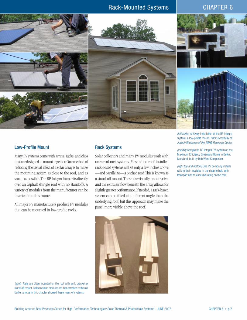
Building America Best Practices Series for High-Performance Technologies: Solar Thermal & Photovoltaic Systems - JUNE 2007 CHAPTER 6 / p.7
Rack-Mounted Systems CHAPTER 6
Low-Profile Mount
Many PV systems come with arrays, racks, and clips that are designed to mount together. One method of reducing the visual effect of a solar array is to make the mounting system as close to the roof, and as small, as possible. The BP Integra frame sits directly over an asphalt shingle roof with no standoffs. A variety of modules from the manufacturer can be inserted into this frame.
All major PV manufacturers produce PV modules that can be mounted in low-profile racks.
Rack Systems
Solar collectors and many PV modules work with universal rack systems. Most of the roof-installed rack-based systems will sit only a few inches above —and parallel to—a pitched roof. This is known as a stand-off mount. These are visually unobtrusive and the extra air flow beneath the array allows for slightly greater performance. If needed, a rack-based system can be tilted at a different angle than the underlying roof, but this approach may make the panel more visible above the roof.
(left series of three) Installation of the BP Integra System, a low-profile mount. Photos courtesy of Joseph Wiehagen of the NAHB Research Center.
(middle) Completed BP Integra PV system on the Maximum Efficiency Greenland Home in BelAir, Maryland, built by Bob Ward Companies.
(right top and bottom) One PV company installs rails to their modules in the shop to help with transport and to ease mounting on the roof.
(right) Rails are often mounted on the roof with an L bracket or stand-off mount. Collectors and modules are then attached to the rail. Earlier photos in this chapter showed these types of systems.
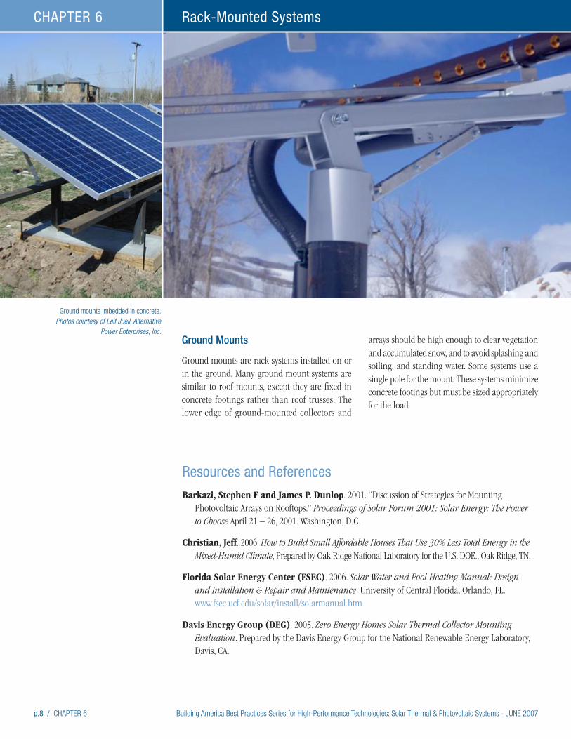
p.8 / CHAPTER 6 Building America Best Practices Series for High-Performance Technologies: Solar Thermal & Photovoltaic Systems - JUNE 2007
Rack-Mounted SystemsCHAPTER 6
Ground mounts imbedded in concrete. Photos courtesy of Leif Juell, Alternative
Power Enterprises, Inc.
Resources and References
Barkazi, Stephen F and James P. Dunlop. 2001. “Discussion of Strategies for Mounting Photovoltaic Arrays on Rooftops.” Proceedings of Solar Forum 2001: Solar Energy: The Power to Choose April 21 – 26, 2001. Washington, D.C.
Christian, Jeff. 2006. How to Build Small Affordable Houses That Use 30% Less Total Energy in the Mixed-Humid Climate, Prepared by Oak Ridge National Laboratory for the U.S. DOE., Oak Ridge, TN.
Florida Solar Energy Center (FSEC). 2006. Solar Water and Pool Heating Manual: Design and Installation & Repair and Maintenance. University of Central Florida, Orlando, FL. www.fsec.ucf.edu/solar/install/solarmanual.htm
Davis Energy Group (DEG). 2005. Zero Energy Homes Solar Thermal Collector Mounting Evaluation. Prepared by the Davis Energy Group for the National Renewable Energy Laboratory, Davis, CA.
Ground Mounts
Ground mounts are rack systems installed on or in the ground. Many ground mount systems are similar to roof mounts, except they are fixed in concrete footings rather than roof trusses. The lower edge of ground-mounted collectors and
arrays should be high enough to clear vegetation and accumulated snow, and to avoid splashing and soiling, and standing water. Some systems use a single pole for the mount. These systems minimize concrete footings but must be sized appropriately for the load.
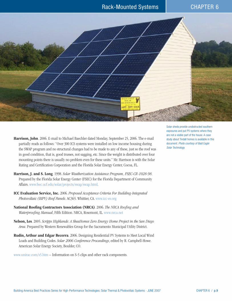
Building America Best Practices Series for High-Performance Technologies: Solar Thermal & Photovoltaic Systems - JUNE 2007 CHAPTER 6 / p.9
Rack-Mounted Systems CHAPTER 6
Harrison, John. 2006. E-mail to Michael Baechler dated Monday, September 25, 2006. The e-mail partially reads as follows: “Over 300 ICS systems were installed on low income housing during the SWAP program and no structural changes had to be made to any of these, just so the roof was in good condition, that is, good trusses, not sagging, etc. Since the weight is distributed over four mounting points there is usually no problem even for these units.” Mr. Harrison is with the Solar Rating and Certification Corporation and the Florida Solar Energy Center, Cocoa, FL.
Harrison, J. and S. Long. 1998. Solar Weatherization Assistance Program, FSEC-CR-1028-98. Prepared by the Florida Solar Energy Center (FSEC) for the Florida Department of Community Affairs. www.fsec.ucf.edu/solar/projects/swap/swap.html.
ICC Evaluation Service, Inc. 2006. Proposed Acceptance Criteria For Building-Integrated Photovoltaic (BIPV) Roof Panels. AC365. Whittier, CA. www.icc-es.org
National Roofing Contractors Association (NRCA). 2006. The NRCA Roofing and Waterproofing Manual, Fifth Edition. NRCA, Rosemont, IL. www.nrca.net
Nelson, Les. 2005. Scripps Highlands: A SheaHomes Zero Energy Home Project in the San Diego Area. Prepared by Western Renewables Group for the Sacramento Municipal Utility District.
Rudin, Arthur and Edgar Becerra. 2006. Designing Residential PV Systems to Meet Local Wind Loads and Building Codes. Solar 2006 Conference Proceedings, edited by R. Campbell-Howe. American Solar Energy Society, Boulder, CO.
www.unirac.com/s5.htm – Information on S-5 clips and other rack components.
Solar sheds provide unobstructed southern exposures and put PV systems where they are not a visible part of the house. A case study about Tindall homes is available in this document. Photo courtesy of Bald Eagle Solar Technology.

Building America Best Practices Series for High-Performance Technologies: Solar Thermal & Photovoltaic Systems - JUNE 2007 CHAPTER 7 / p.1
High-Performance Home Technologies: Solar Thermal & Photovoltaic Systems
Chapter 7. Worker Safety
Building America Best Practices Series
Sunglasses, hardhats, and harnesses protect this crew from glare and falls. Builders must recognize that, ultimately, they may be held accountable for compliance with worker safety regulations. Although not required by regulation, protection for workers from solar exposure is important. Photo courtesy of NREL.
OSHA (2005) lists the standards most frequently included in the agency’s citations in FY 2004 as the following:
1. Scaffolding
2. Fall protection (scope, application, definitions)
3. Excavations (general requirements)
4. Ladders
5. Head protection
6. Excavations (requirements for protective systems)
7. Hazard communication
8. Fall protection (training requirements)
9. Construction (general safety and health provisions)
10. Electrical (wiring methods, design and protection).
Most of these standards are relevant to solar installations.
FallsFall hazards are the most common serious issue in construction. OSHA regulations for fall protection are covered in Part 1926, Subpart M. The regulations for fall protection apply to any work conducted greater than 6 feet above the ground.
OSHA offers the following tips to avoid fall hazards:
• Identify and evaluate fall hazards, including slick surfaces created by weather or jobsite activities.
• Mitigate any hazards you can – cover holes, keep the job area as clean as possible.
• Use appropriate equipment to prevent falls.
• Make sure fall-protection equipment is in good working order.
OSHA offers the following control measure sugges-tions to mitigate the most serious hazards for which employers have been cited most often:
Builders’ & Installers’ Brief
• Ultimately, the builder may be
responsible for jobsite Occupational
Safety and Health Administration
(OSHA) violations.
• Falls are the number one cause of
worker injury in house construction.
• Fall protection regulations apply to
any work situation greater than 6 feet
above ground.
• Do as much work as possible on
the ground.
• Encourage protection against
exposure to the sun’s rays.
• PV modules are energized whenever
struck by light. Workers must be
protected from electrical hazards.
• Solar thermal installers work with
plumbing processes that include open
flame. Precautions must be taken to
protect workers and structures from
flame and hot solder.
The Occupational Safety and Health Act of 1970 (the Act) generally covers all employers and employees in the U.S., including U.S. Territories. The Federal Occupational Safety and Health Administration (OSHA) administers and enforces the act. OSHA sets standards and conducts inspections to help ensure safe workplaces. The Act provides for penalties including fines and imprisonment depending upon the violation. States with their own plans can have different penalties.
Standards applicable to construction are contained in Title 29 of the U.S. Code of Federal Regulations, Part 1926, Safety and Health Regulations for Construction (29 CFR 1926).
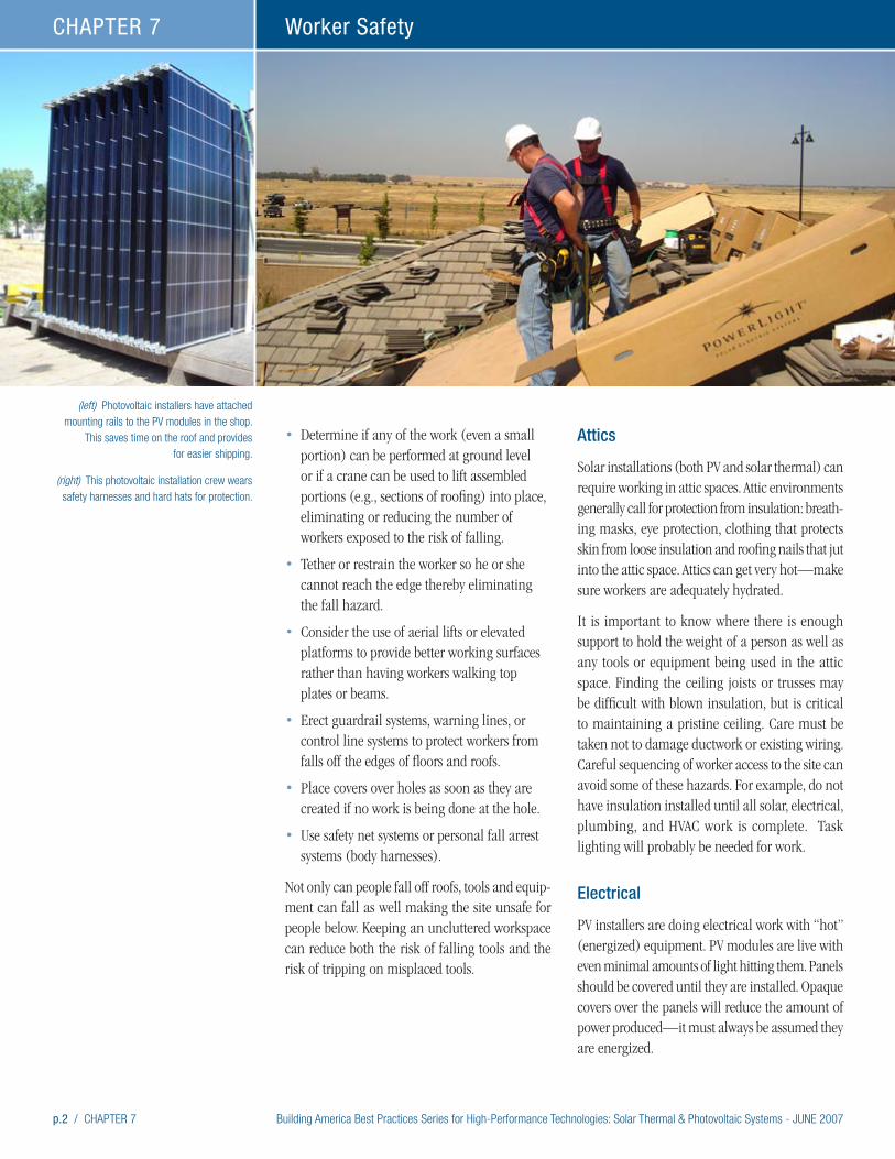
p.2 / CHAPTER 7 Building America Best Practices Series for High-Performance Technologies: Solar Thermal & Photovoltaic Systems - JUNE 2007
Worker SafetyCHAPTER 7
• Determine if any of the work (even a small portion) can be performed at ground level or if a crane can be used to lift assembled portions (e.g., sections of roofing) into place, eliminating or reducing the number of workers exposed to the risk of falling.
• Tether or restrain the worker so he or she cannot reach the edge thereby eliminating the fall hazard.
• Consider the use of aerial lifts or elevated platforms to provide better working surfaces rather than having workers walking top plates or beams.
• Erect guardrail systems, warning lines, or control line systems to protect workers from falls off the edges of floors and roofs.
• Place covers over holes as soon as they are created if no work is being done at the hole.
• Use safety net systems or personal fall arrest systems (body harnesses).
Not only can people fall off roofs, tools and equip-ment can fall as well making the site unsafe for people below. Keeping an uncluttered workspace can reduce both the risk of falling tools and the risk of tripping on misplaced tools.
Attics
Solar installations (both PV and solar thermal) can require working in attic spaces. Attic environments generally call for protection from insulation: breath-ing masks, eye protection, clothing that protects skin from loose insulation and roofing nails that jut into the attic space. Attics can get very hot—make sure workers are adequately hydrated.
It is important to know where there is enough support to hold the weight of a person as well as any tools or equipment being used in the attic space. Finding the ceiling joists or trusses may be difficult with blown insulation, but is critical to maintaining a pristine ceiling. Care must be taken not to damage ductwork or existing wiring. Careful sequencing of worker access to the site can avoid some of these hazards. For example, do not have insulation installed until all solar, electrical, plumbing, and HVAC work is complete. Task lighting will probably be needed for work.
Electrical
PV installers are doing electrical work with “hot” (energized) equipment. PV modules are live with even minimal amounts of light hitting them. Panels should be covered until they are installed. Opaque covers over the panels will reduce the amount of power produced—it must always be assumed they are energized.
(left) Photovoltaic installers have attached mounting rails to the PV modules in the shop.
This saves time on the roof and provides for easier shipping.
(right) This photovoltaic installation crew wears safety harnesses and hard hats for protection.
Building America Best Practices Series for High-Performance Technologies: Solar Thermal & Photovoltaic Systems - JUNE 2007 CHAPTER 7 / p.3
Worker Safety CHAPTER 7
Foot protection should not only have impact and compression resistance, it should also be rated EH for electrical hazard or electrical shock resistance as specified in OSHA guidelines. Electrical hazard footwear is manufactured with non-conductive electrical shock-resistant soles and heels. It is intended to provide a secondary source of protec-tion against accidental contact with live electrical circuits, electrically energized conductors, parts or apparatus.
The North American Board of Certified Energy Practitioners (NABCEP 2005) notes that the following sections of the OSHA rules apply to PV installation sites:
• Subpart I – Tools, Hand and Power
• Subpart K – Electrical
• Subpart X – Stairways and Ladders.
Plumbing
Solar thermal installers often deal with plumbing equipment and processes, such as using torches for soldering or possible exposure to very hot water or steam. These hazards can not only injure workers, they can damage roofs and other structural and finish materials. Dripping solder can damage unprotected skin, as well as newly installed flooring or paint.
NABCEP (2006) notes solar thermal installations are also covered by the following OSHA rules:
• Subpart P – Tools, Hand, and Portable Power Tools
• Subpart Q – Welding, Cutting, Brazing.
Lifting and Handling
PV modules for solar thermal collectors are heavy and the metal surrounding them can get very hot in the sun. If a module is dropped, jagged edges can be dangerous. Gloves can help protect workers from these hazards. Hard hats should be worn whenever there is a hazard of materials falling from above.
Roof-mounted solar systems require lifting large parts onto roofs creating lifting hazards. Solar PV
systems can be large and ungainly and involve many pieces. Solar thermal collectors are heavier and may require more than one person or machin-ery to lift onto a roof. Even ground-level work on a solar PV system can require heavy lifting: some inverters weigh over 150 pounds and may require two people to lift to their mounting places.
The National Institute for Occupational Safety and Health (NIOSH) recommends that employers and workers minimize their risk of back injury by developing and implementing a comprehensive ergonomics program. A program of this nature would focus on prevention (www.cdc.gov/niosh/homepage.html).
The Labor Occupational Health Program at Univer-sity of California Berkeley has created a checklist to help reduce lifting hazards (http://socrates.berkeley.edu/~lohp/graphics/pdf/cBACKS.pdf). This list is based on California regulations, but is sensible in any state. The list helps define for builders what lifting hazards are. These include:
• Heavy loads including 20-pound objects that are lifted repeatedly and 50-pound objects that are lifted at one time.
• Bulky or awkward objects
• Loads whose weight may suddenly shift
• Objects that must be lifted from above shoulder level
• Objects that must be lifted from the floor
• Objects that cannot be held close to the body.
The checklist also provides guidance to help reduce lifting hazards. Some of the recommendations include the following:
• Encourage workers to stretch and warm up before lifting and to take frequent stretch breaks.
• Train workers on lifting methods.
• Use mechanical lifting devices (fork lifts, hoists, cranes, and block and tackle).
• Ensure that manual lifting and carrying devices (dollies, hand trucks, pry bars, and hooks) are available and in good condition.
p.4 / CHAPTER 7 Building America Best Practices Series for High-Performance Technologies: Solar Thermal & Photovoltaic Systems - JUNE 2007
Worker SafetyCHAPTER 7
• Split up materials to reduce weight.
• Deliver materials as close as possible to the work site.
• Divide lifting tasks among workers or use team lifting.
• Store heavy materials that must be lifted manuallyabove the ground, no lower than knee height. (This limits the height of the lifting required, and reduces pressure on the spine.)
• Store heavy materials where there is enough space to lift them safely, without reaching or twisting.
Responsibility for ViolationsEmployers are responsible to ensure that the requirements of the Act are met. However, in most situations this could be confusing when there might be a general contractor, subcontractors, and even third-tier subcontractors. OSHA ultimately is looking at who has control of the jobsite.
According to part 1926.16(a), prime contractors and subcontractors may agree who is responsible for items such as first aid, etc., on the jobsite, but legal responsibility cannot be abdicated. “In no case shall the prime contractor be relieved of overall responsibility for compliance with the requirements of this part for all work to be performed under the contract.” Parts 1926.16(c) and (d) address joint responsibility among prime contractors and subcontractors. Details can be found at: www.osha.gov/pls/oshaweb/owadisp.show_document?p_table=STANDARDS&p_id=10605.
Injured workers, even if they work for a third-tier subcontractor, may have a claim against the prime contractor in certain circumstances. In some states, general contractors may have to pay claims for injuries when subcontractors and third-tier subs have no workers’ comp insurance.
EnforcementOSHA has 10 regional offices and many area offices. A list of the offices is provided at www.osha-slc.gov/htmol/RAmap.html. Section 18 of the Act allows states to adopt their own standards under supervision of OSHA. According to OSHA’s website (www.osha.gov), “There are currently 22 States and jurisdictions operating complete State plans (covering both the private sector and State and local government employees) and 4 – Connecticut, New Jersey, New York, and U.S. Virgin Islands – which cover public employees only.” When OSHA grants final approval to a state under Section 18(e) of the Act, it “relinquishes its authority to cover occupational safety and health matters covered by the State.” It is very important, therefore, to be aware of states that have their own OSHA programs: www.osha.gov/fso/osp/faq.html#oshaprogram.
Since resources are limited, “targets” are used to determine sites that will be inspected. “Targets” include past bad performers. In addition, “programmed inspections” are conducted which focus on high-hazard groups/industries that have the highest injury rates. When certain circumstances occur, such as a fatality, a complaint, or a referral, an “unprogrammed inspection” may be conducted. Local enforcers may also just “drive by” job sites.
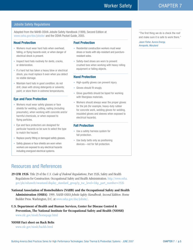
Building America Best Practices Series for High-Performance Technologies: Solar Thermal & Photovoltaic Systems - JUNE 2007 CHAPTER 7 / p.5
Worker Safety CHAPTER 7
Resources and References
29 CFR 1926. Title 29 of the U.S. Code of Federal Regulations, Part 1926, Safety and Health Regulations for Construction. Occupational Safety and Health Administration. http://www.osha.gov/pls/oshaweb/owastand.display_standard_group?p_toc_level=1&p_part_number=1926
National Association of Homebuilders (NAHB) and the Occupational Safety and Health Administration (OSHA). 1999. NAHB-OSHA Jobsite Safety Handbook, Second Edition. Home Builder Press. Washington, D.C. at www.osha.gov/doc/jobsite/.
U.S. Department of Health and Human Services, Center for Disease Control & Prevention, The National Institute for Occupational Safety and Health (NIOSH) www.cdc.gov/niosh/homepage.html
NIOSH Fact sheet on Back Belts www.cdc.gov/niosh/backfs.html
“The first thing we do is check the roof
and make sure it is safe to work there.” Jason Fisher, Aurora Energy, Annapolis, Maryland
Head Protection
• Workers must wear hard hats when overhead, falling, or flying hazards exist, or when danger of electrical shock is present.
• Inspect hard hats routinely for dents, cracks, or deterioration.
• If a hard hat has taken a heavy blow or electrical shock, you must replace it even when you detect no visible damage.
• Maintain hard hats in good condition; do not drill; clean with strong detergents or solvents; paint; or store them in extreme temperatures.
Eye and Face Protection
• Workers must wear safety glasses or face shields for welding, cutting, nailing (including pneumatic), when working with concrete and/or harmful chemicals, or when exposed to flying particles.
• Eye and face protectors are designed for particular hazards so be sure to select the type to match the hazard.
• Replace poorly fitting or damaged safety glasses.
• Safety glasses or face shields are worn when workers are exposed to any electrical hazards including energized electrical systems.
Foot Protection
• Residential construction workers must wear shoes or boots with slip-resistant and puncture-resistant soles.
• Safety-toed shoes are worn to prevent crushed toes when working with heavy rolling equipment or falling objects.
Hand Protection
• High-quality gloves can prevent injury.
• Gloves should fit snugly.
• Glove gauntlets should be taped for working with fiberglass materials.
• Workers should always wear the proper gloves for the job (for example, heavy-duty rubber for concrete work, welding gloves for welding, insulated gloves and sleeves when exposed to electrical hazards).
Fall Protection
• Use a safety harness system for fall protection.
• Use body belts only as positioning devices—not for fall protection.
Jobsite Safety Regulations
Adapted from the NAHB-OSHA Jobsite Safety Handbook (1999), Second Edition at www.osha.gov/doc/jobsite/ and the OSHA Pocket Guide, 2005.

p.6 / CHAPTER 7 Building America Best Practices Series for High-Performance Technologies: Solar Thermal & Photovoltaic Systems - JUNE 2007
Worker SafetyCHAPTER 7
Electronic Library of Construction Occupational Safety & Health (eLCOSH), funded by NIOSH www.cdc.gov/elcosh/index.html
State of California, Department of Industrial Relations, Division of Occupational Safety and Health (DOSH) enforces California Occupational Safety & Health Administration (Cal/OSHA) regulations www.dir.ca.gov/dosh/dosh1.html
Labor Occupational Health Program, School of Public Health, University of California at Berkeley. A community outreach program that addresses health and safety needs in nearly every industry. They have publications, training programs, a free library, and a telephone reference service. They are geared toward safety in California but have references at a federal level as well. Some of their information is in multi-lingual format. www.lohp.org
http://socrates.berkeley.edu/~lohp/graphics/pdf/cBACKS.pdf follows Cal/OSHA code, but is a great checklist to help reduce lifting hazards.
North American Board of Certified Energy Practitioners (NABCEP). 2005. NABCEP Study Guide for Photovoltaic System Installers and Sample Examination Questions Revision 3. Prepared for the U.S. Department of Energy and Sandia National Laboratories. www.nabcep.org/Monticello/userfiles/File/PVStudyGuide093006FINAL.pdf
North American Board of Certified Energy Practitioners (NABCEP). 2006. NABCEP Study Guide for Solar Water and Pool Heating System Installers and Sample Questions With Answer Key, Version 1. Prepared for NABCEP by the Florida Solar Energy Center and Energy Conservation Services. www.nabcep.org/Monticello/userfiles/File/NABCEPSolarThermalStudyGuideVersion1.0.pdf
Occupational Safety and Health Administration (OSHA). 2005. OSHA Pocket Guide 3252-05N 2005. U.S. Department of Labor, Washington, D.C. www.osha.gov/Publications/OSHA3252/3252.html
Solar Energy International (SEI). 2004. Photovoltaics: Design and Installation Manual. New Society Publishers, Gabriola Island, British Columbia, Canada www.solarenergy.org
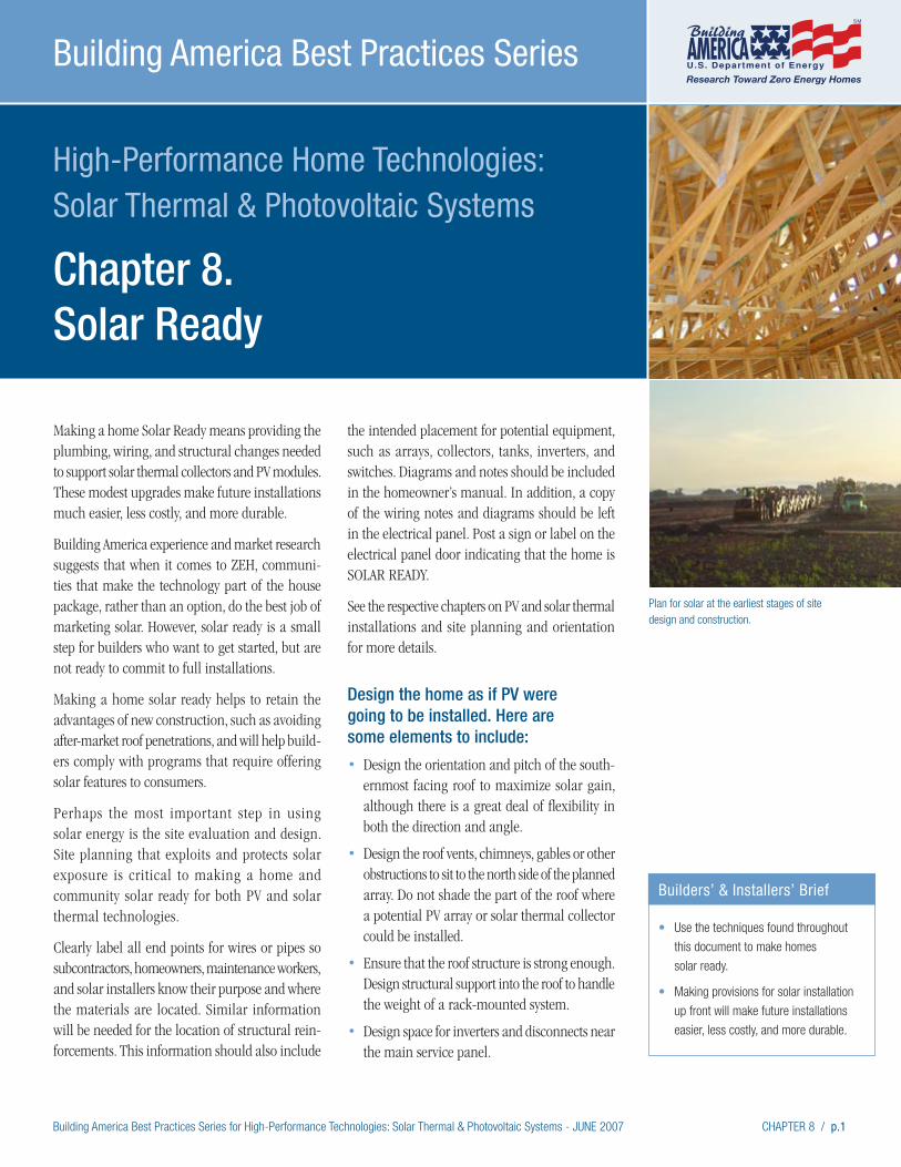
Building America Best Practices Series for High-Performance Technologies: Solar Thermal & Photovoltaic Systems - JUNE 2007 CHAPTER 8 / p.1
High-Performance Home Technologies: Solar Thermal & Photovoltaic Systems
Chapter 8. Solar Ready
Building America Best Practices Series
Making a home Solar Ready means providing the plumbing, wiring, and structural changes needed to support solar thermal collectors and PV modules. These modest upgrades make future installations much easier, less costly, and more durable.
Building America experience and market research suggests that when it comes to ZEH, communi-ties that make the technology part of the house package, rather than an option, do the best job of marketing solar. However, solar ready is a small step for builders who want to get started, but are not ready to commit to full installations.
Making a home solar ready helps to retain the advantages of new construction, such as avoiding after-market roof penetrations, and will help build-ers comply with programs that require offering solar features to consumers.
Perhaps the most important step in using solar energy is the site evaluation and design. Site planning that exploits and protects solar exposure is critical to making a home and community solar ready for both PV and solar thermal technologies.
Clearly label all end points for wires or pipes so subcontractors, homeowners, maintenance workers, and solar installers know their purpose and where the materials are located. Similar information will be needed for the location of structural rein-forcements. This information should also include
the intended placement for potential equipment, such as arrays, collectors, tanks, inverters, and switches. Diagrams and notes should be included in the homeowner’s manual. In addition, a copy of the wiring notes and diagrams should be left in the electrical panel. Post a sign or label on the electrical panel door indicating that the home is SOLAR READY.
See the respective chapters on PV and solar thermal installations and site planning and orientation for more details.
Design the home as if PV were going to be installed. Here are some elements to include:
• Design the orientation and pitch of the south-ernmost facing roof to maximize solar gain, although there is a great deal of flexibility in both the direction and angle.
• Design the roof vents, chimneys, gables or other obstructions to sit to the north side of the planned array. Do not shade the part of the roof where a potential PV array or solar thermal collector could be installed.
• Ensure that the roof structure is strong enough. Design structural support into the roof to handle the weight of a rack-mounted system.
• Design space for inverters and disconnects near the main service panel.
Builders’ & Installers’ Brief
• Use the techniques found throughout
this document to make homes
solar ready.
• Making provisions for solar installation
up front will make future installations
easier, less costly, and more durable.
Plan for solar at the earliest stages of site design and construction.
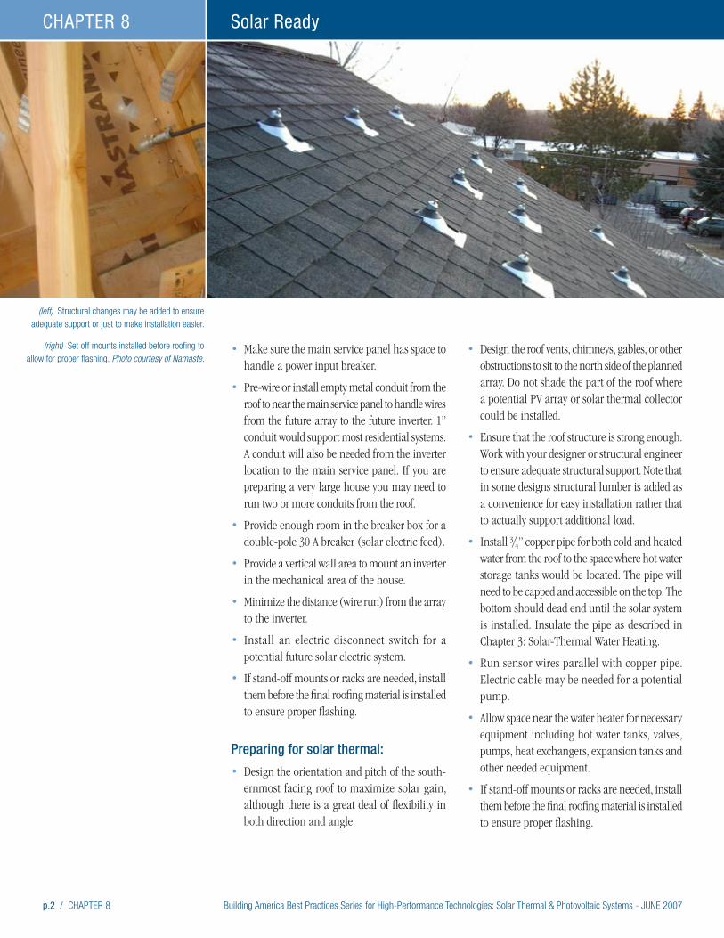
p.2 / CHAPTER 8 Building America Best Practices Series for High-Performance Technologies: Solar Thermal & Photovoltaic Systems - JUNE 2007
Solar ReadyCHAPTER 8
• Make sure the main service panel has space to handle a power input breaker.
• Pre-wire or install empty metal conduit from the roof to near the main service panel to handle wires from the future array to the future inverter. 1” conduit would support most residential systems. A conduit will also be needed from the inverter location to the main service panel. If you are preparing a very large house you may need to run two or more conduits from the roof.
• Provide enough room in the breaker box for a double-pole 30 A breaker (solar electric feed).
• Provide a vertical wall area to mount an inverter in the mechanical area of the house.
• Minimize the distance (wire run) from the array to the inverter.
• Install an electric disconnect switch for a potential future solar electric system.
• If stand-off mounts or racks are needed, install them before the final roofing material is installed to ensure proper flashing.
Preparing for solar thermal:
• Design the orientation and pitch of the south-ernmost facing roof to maximize solar gain, although there is a great deal of flexibility in both direction and angle.
• Design the roof vents, chimneys, gables, or other obstructions to sit to the north side of the planned array. Do not shade the part of the roof where a potential PV array or solar thermal collector could be installed.
• Ensure that the roof structure is strong enough. Work with your designer or structural engineer to ensure adequate structural support. Note that in some designs structural lumber is added as a convenience for easy installation rather that to actually support additional load.
• Install 3/4” copper pipe for both cold and heated water from the roof to the space where hot water storage tanks would be located. The pipe will need to be capped and accessible on the top. The bottom should dead end until the solar system is installed. Insulate the pipe as described in Chapter 3: Solar-Thermal Water Heating.
• Run sensor wires parallel with copper pipe. Electric cable may be needed for a potential pump.
• Allow space near the water heater for necessary equipment including hot water tanks, valves, pumps, heat exchangers, expansion tanks and other needed equipment.
• If stand-off mounts or racks are needed, install them before the final roofing material is installed to ensure proper flashing.
(left) Structural changes may be added to ensure adequate support or just to make installation easier.
(right) Set off mounts installed before roofing to allow for proper flashing. Photo courtesy of Namaste.
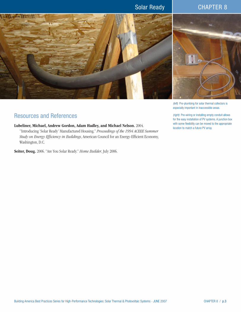
Building America Best Practices Series for High-Performance Technologies: Solar Thermal & Photovoltaic Systems - JUNE 2007 CHAPTER 8 / p.3
Solar Ready CHAPTER 8
Resources and References
Lubeliner, Michael, Andrew Gordon, Adam Hadley, and Michael Nelson. 2004. “Introducing ‘Solar Ready’ Manufactured Housing.” Proceedings of the 1994 ACEEE Summer Study on Energy Efficiency in Buildings, American Council for an Energy-Efficient Economy, Washington, D.C.
Seiter, Doug. 2006. “Are You Solar Ready.” Home Builder, July 2006.
(left) Pre-plumbing for solar thermal collectors is especially important in inaccessible areas.
(right) Pre-wiring or installing empty conduit allows for the easy installation of PV systems. A junction box with some flexibility can be moved to the appropriate location to match a future PV array.
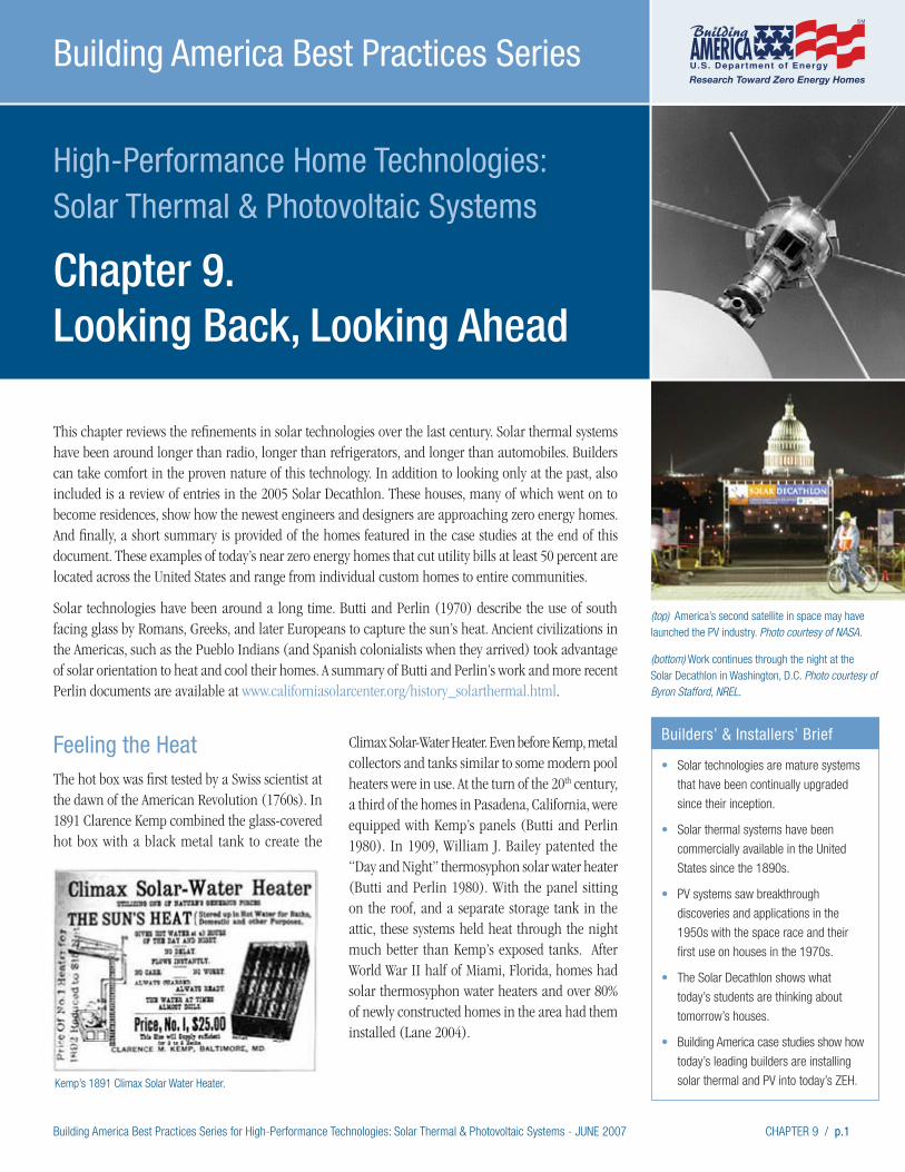
Building America Best Practices Series for High-Performance Technologies: Solar Thermal & Photovoltaic Systems - JUNE 2007 CHAPTER 9 / p.1
High-Performance Home Technologies: Solar Thermal & Photovoltaic Systems
Chapter 9. Looking Back, Looking Ahead
Building America Best Practices Series
(top) America’s second satellite in space may have launched the PV industry. Photo courtesy of NASA.
(bottom) Work continues through the night at the Solar Decathlon in Washington, D.C. Photo courtesy of Byron Stafford, NREL.
Feeling the HeatThe hot box was first tested by a Swiss scientist at the dawn of the American Revolution (1760s). In 1891 Clarence Kemp combined the glass-covered hot box with a black metal tank to create the
Climax Solar-Water Heater. Even before Kemp, metal collectors and tanks similar to some modern pool heaters were in use. At the turn of the 20th century, a third of the homes in Pasadena, California, were equipped with Kemp’s panels (Butti and Perlin 1980). In 1909, William J. Bailey patented the “Day and Night” thermosyphon solar water heater (Butti and Perlin 1980). With the panel sitting on the roof, and a separate storage tank in the attic, these systems held heat through the night much better than Kemp’s exposed tanks. After World War II half of Miami, Florida, homes had solar thermosyphon water heaters and over 80% of newly constructed homes in the area had them installed (Lane 2004).
This chapter reviews the refinements in solar technologies over the last century. Solar thermal systems have been around longer than radio, longer than refrigerators, and longer than automobiles. Builders can take comfort in the proven nature of this technology. In addition to looking only at the past, also included is a review of entries in the 2005 Solar Decathlon. These houses, many of which went on to become residences, show how the newest engineers and designers are approaching zero energy homes. And finally, a short summary is provided of the homes featured in the case studies at the end of this document. These examples of today’s near zero energy homes that cut utility bills at least 50 percent are located across the United States and range from individual custom homes to entire communities.
Solar technologies have been around a long time. Butti and Perlin (1970) describe the use of south facing glass by Romans, Greeks, and later Europeans to capture the sun’s heat. Ancient civilizations in the Americas, such as the Pueblo Indians (and Spanish colonialists when they arrived) took advantage of solar orientation to heat and cool their homes. A summary of Butti and Perlin’s work and more recent Perlin documents are available at www.californiasolarcenter.org/history_solarthermal.html.
Builders’ & Installers’ Brief
• Solar technologies are mature systems
that have been continually upgraded
since their inception.
• Solar thermal systems have been
commercially available in the United
States since the 1890s.
• PV systems saw breakthrough
discoveries and applications in the
1950s with the space race and their
first use on houses in the 1970s.
• The Solar Decathlon shows what
today’s students are thinking about
tomorrow’s houses.
• Building America case studies show how
today’s leading builders are installing
solar thermal and PV into today’s ZEH.Kemp’s 1891 Climax Solar Water Heater.

p.2 / CHAPTER 9 Building America Best Practices Series for High-Performance Technologies: Solar Thermal & Photovoltaic Systems - JUNE 2007
Looking Back, Looking Ahead CHAPTER 9
Modern solar thermal systems and companies in the United States have been around since the 1970s. Interest in solar started picking up after the oil crisis that developed during the OPEC (Organization of Petroleum Exporting Countries) oil embargo of the U.S. after the Arab-Israeli war in 1973. In that same year the University of Delaware built Solar One, the first residence outfitted with PVs (www.lib.udel.edu/ud/spec/findaids/boer/index.htm). The house had a grid-tied PV system and had a net metering arrangement with its utility. It was also outfitted with solar-thermal collectors used for space heating.
Another war along the Israeli-Lebanese border and a revolution in Iran disrupted oil supplies and began pushing prices up again in 1978. This time, 40% federal tax credits were enacted for solar thermal installations. The tax credits proved both blessing and curse to the emerging solar industry. Solar thermal technologies were not well developed and a quickly growing market brought in many new companies that had little experience with the technology or the installations. Memories of failed systems from that era still haunt installers, builders, and consumers. However, many systems installed in the 1980s still perform.
Finding the LightWilliam Grylls Adams and Richard Evans Day discovered in 1876 that light shined on solid sele-nium would produce an electric current (Perlin 1999). Over 75 years later, scientists at Bell Labo-ratories inadvertently made a more efficient solar cell that, with refinement, could power electrical equipment. Sputnik in 1957 and the subsequent race for space turned the new photovoltaics from novelties to power sources. Vanguard 1, launched in 1958 as America’s second artificial satellite, is the oldest manufactured satellite still orbiting earth, and was the first to use photovoltaics (Green and Lomask 1970). It continued to transmit for 5 years, until 1964. In comparison, America’s first satellite, Explorer 1, which was equipped with a nickel cadmium battery, had power to transmit for 105 days. (See www.nasm.si.edu/research/dsh/ artifacts/SS-vanguard.htm).
With more than a century of technical innovation in the solar industry, and with widespread use in times and places of energy scarcity, another point becomes clear. As an energy source for consumers, solar competes with natural gas and electricity. Electricity cost and availability is dependent on coal, oil, water flow and other factors facing
Progress on development of the International Space Station can be traced through the
addition of PV systems. The latest installment came in September 2006 (top right).
Photos courtesy of NASA.
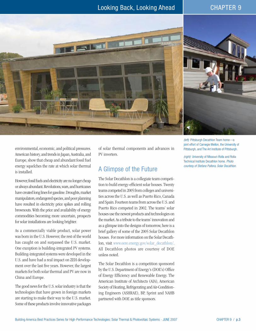
Building America Best Practices Series for High-Performance Technologies: Solar Thermal & Photovoltaic Systems - JUNE 2007 CHAPTER 9 / p.3
Looking Back, Looking Ahead CHAPTER 9
environmental, economic, and political pressures. American history, and trends in Japan, Australia, and Europe, show that cheap and abundant fossil fuel energy squelches the rate at which solar thermal is installed.
However, fossil fuels and electricity are no longer cheap or always abundant. Revolutions, wars, and hurricanes have created long lines for gasoline. Droughts, market manipulators, endangered species, and poor planning have resulted in electricity price spikes and rolling brownouts. With the price and availability of energy commodities becoming more uncertain, prospects for solar installations are looking brighter.
As a commercially viable product, solar power was born in the U.S. However, the rest of the world has caught on and surpassed the U.S. market. One exception is building-integrated PV systems. Building-integrated systems were developed in the U.S. and have had a real impact on ZEH develop-ment over the last five years. However, the largest markets for both solar thermal and PV are now in China and Europe.
The good news for the U.S. solar industry is that the technologies that have grown in foreign markets are starting to make their way to the U.S. market. Some of these products involve innovative packages
of solar thermal components and advances in PV inverters.
A Glimpse of the FutureThe Solar Decathlon is a collegiate team competi-tion to build energy-efficient solar houses. Twenty teams competed in 2005 from colleges and universi-ties across the U.S. as well as Puerto Rico, Canada and Spain. Fourteen teams from across the U.S. and Puerto Rico competed in 2002. The teams’ solar houses use the newest products and technologies on the market. As a tribute to the teams’ innovation and as a glimpse into the designs of tomorrow, here is a brief gallery of some of the 2005 Solar Decathlon houses. For more information on the Solar Decath-lon, visit www.eere.energy.gov/solar_decathlon/. All Decathlon photos are courtesy of DOE unless noted.
The Solar Decathlon is a competition sponsored by the U.S. Department of Energy’s (DOE’s) Office of Energy Efficiency and Renewable Energy. The American Institute of Architects (AIA), American Society of Heating, Refrigerating and Air-Condition-ing Engineers (ASHRAE), BP, Sprint and NAHB partnered with DOE as title sponsors.
(left) Pittsburgh Decathlon Team home—a joint effort of Carnegie Mellon, the University of Pittsburgh, and The Art Institute of Pittsburgh.
(right) University of Missouri-Rolla and Rolla Technical Institute Decathlon home. Photo courtesy of Stefano Paltera, Solar Decathlon.
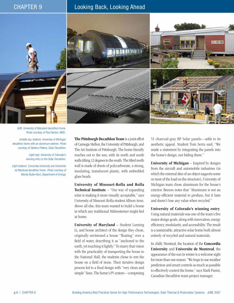
p.4 / CHAPTER 9 Building America Best Practices Series for High-Performance Technologies: Solar Thermal & Photovoltaic Systems - JUNE 2007
Looking Back, Looking Ahead CHAPTER 9
The Pittsburgh Decathlon Team is a joint effort of Carnegie Mellon, the University of Pittsburgh, and The Art Institute of Pittsburgh. The home literally reaches out to the sun, with its north and south walls tilting 12 degrees to the south. The tilted north wall is made of sheets of polycarbonate, a strong, insulating, translucent plastic, with embedded glass beads.
University of Missouri-Rolla and Rolla Technical Institute – “Our way of expanding solar is making it more visually acceptable,” says University of Missouri-Rolla student Allison Arnn. Above all else, this team wanted to build a house in which any traditional Midwesterner might feel at home.
University of Maryland – Student Luming Li, and house architect of the design they chose, originally envisioned a house “floating” over a field of water, describing it as “anchored to the earth, yet touching it lightly.” To marry that vision with the practicality of transporting the house to the National Mall, the students chose to rest the house on a field of stone. Their iterative design process led to a final design with “very clean and simple” lines. The home’s PV system—comprising
51 charcoal-gray BP Solar panels—adds to its aesthetic appeal. Student Tom Serra said, “We made a statement by integrating the panels into the home’s design, not hiding them.”
University of Michigan – Inspired by designs from the aircraft and automobile industries (in which the external skin of an object supports some or most of the load on the structure), University of Michigan team chose aluminum for the house’s exterior. Beeson notes that “Aluminum is not an energy-efficient material to produce, but it lasts and doesn’t lose any value when recycled.”
University of Colorado’s winning entry. Using natural materials was one of the team’s five major design goals, along with innovation, energy efficiency, modularity, and accessibility. The result is a sustainable, attractive solar home built almost entirely of recycled and natural materials.
In chilly Montreal, the location of the Concordia University and Universite de Montreal, the appearance of the sun in winter is a welcome sight for more than one reason. “We hope to use weather prediction and smart controls as much as possible to effectively control the home,” says Mark Pasini, Canadian Decathlon team project manager.
(left) University of Maryland decathlon home. Photo courtesy of Paul Norton, NREL.
(middle top, bottom) University of Michigan decathlon home with an aluminum exterior. Photo
courtesy of Stefano Paltera, Solar Decathlon.
(right top) University of Colorado’s winning entry to the Solar Decathlon.
(right bottom) Concordia University and Universite de Montreal decathlon home. Photo courtesy of
Wendy Butler-Burt, Department of Energy.
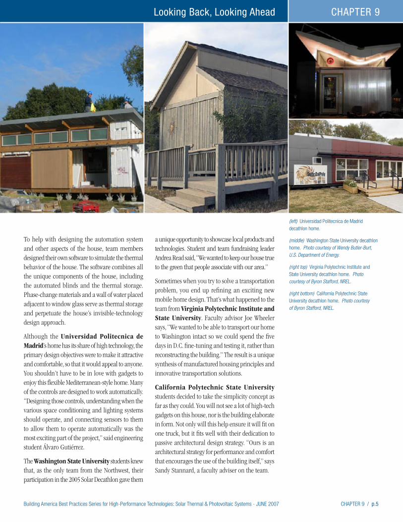
Building America Best Practices Series for High-Performance Technologies: Solar Thermal & Photovoltaic Systems - JUNE 2007 CHAPTER 9 / p.5
Looking Back, Looking Ahead CHAPTER 9
To help with designing the automation system and other aspects of the house, team members designed their own software to simulate the thermal behavior of the house. The software combines all the unique components of the house, including the automated blinds and the thermal storage. Phase-change materials and a wall of water placed adjacent to window glass serve as thermal storage and perpetuate the house’s invisible-technology design approach.
Although the Universidad Politecnica de Madrid’s home has its share of high technology, the primary design objectives were to make it attractive and comfortable, so that it would appeal to anyone. You shouldn’t have to be in love with gadgets to enjoy this flexible Mediterranean-style home. Many of the controls are designed to work automatically. “Designing those controls, understanding when the various space conditioning and lighting systems should operate, and connecting sensors to them to allow them to operate automatically was the most exciting part of the project,” said engineering student Álvaro Gutiérrez.
The Washington State University students knew that, as the only team from the Northwest, their participation in the 2005 Solar Decathlon gave them
a unique opportunity to showcase local products and technologies. Student and team fundraising leader Andrea Read said, “We wanted to keep our house true to the green that people associate with our area.”
Sometimes when you try to solve a transportation problem, you end up refining an exciting new mobile home design. That’s what happened to the team from Virginia Polytechnic Institute and State University. Faculty advisor Joe Wheeler says, “We wanted to be able to transport our home to Washington intact so we could spend the five days in D.C. fine-tuning and testing it, rather than reconstructing the building.” The result is a unique synthesis of manufactured housing principles and innovative transportation solutions.
California Polytechnic State University students decided to take the simplicity concept as far as they could. You will not see a lot of high-tech gadgets on this house, nor is the building elaborate in form. Not only will this help ensure it will fit on one truck, but it fits well with their dedication to passive architectural design strategy. “Ours is an architectural strategy for performance and comfort that encourages the use of the building itself,” says Sandy Stannard, a faculty adviser on the team.
(left) Universidad Politecnica de Madrid decathlon home.
(middle) Washington State University decathlon home. Photo courtesy of Wendy Butler-Burt, U.S. Department of Energy.
(right top) Virginia Polytechnic Institute and State University decathlon home. Photo courtesy of Byron Stafford, NREL.
(right bottom) California Polytechnic State University decathlon home. Photo courtesy of Byron Stafford, NREL.
p.6 / CHAPTER 9 Building America Best Practices Series for High-Performance Technologies: Solar Thermal & Photovoltaic Systems - JUNE 2007
Looking Back, Looking Ahead CHAPTER 9
Samples of the Best of Today’s ZEHBuilders all over the United States are making breakthroughs in the design and construction of ZEH. All of these homes incorporate solar tech-nologies with high levels of energy efficiency. Few homes have met the goal of generating as much power as they consume over the course of a year. But, the builders showcased in the case studies contained in this document have worked with their solar partners and Building America to streamline installations and demonstrate the effectiveness of ZEH technologies for both energy effectiveness and consumer acceptance.
The 13 case studies presented at the end of this document tell the stories of some of the nation’s largest builders like Centex and Pulte, regional production builders like Clarum and Bob Ward Companies, a custom builder, and even affordable housing builders like Habitat for Humanity.
Bob Ward Companies’ Maximum Efficiency Greenland in BelAir, Maryland – Bob Ward Companies took its popular Greenland house model and decided to see just how efficient it could be made. The builder, an energy-efficiency pioneer in Maryland, started with a basement foundation of precast high-density concrete walls with an interior layer of rigid foam insulation plus R-19 of fiberglass bat, and went up with advanced framed upper walls and a whopping R50 blown fiberglass ceiling insulation, plus foam sealing of all band joists, top and bottom plates and wall penetrations. A whole house fan and fresh air intake ensure air quality in the super-tight structure, which Bob Ward has kept open for a year to showcase the 3kW photovoltaic system, solar hot water system, and super-efficient lighting and appliances for regional builders, realtors, and architectural students.
Centex Avignon in Pleasanton, California – Builder of over 350,000 homes, Centex has committed to efficiency on its Avignon development, the first all-solar, zero-energy community to be built in Alameda County. The 3.5 kW PV systems use SunPower integrated Suntiles, which match the
dimensions of the cement roof tiles they replace to blend in seamlessly with the roofing. Other energy-saving measures like R-49 attic insulation and R-15 wall insulation, high-efficiency windows and appliances, caulking, sealing, and independent air leakage testing help ensure energy savings of up to 70% for home owners.
Clarum Homes’ Vista Montana in Watson-ville, California – The largest ZEH development to date when completed in 2005, Vista Montana includes 257 single-family homes and townhouses along with 132 solar-powered apartments, plus a 14-acre park, and an elementary school. This is one of several PV-powered, energy-efficient develop-ments the innovative builder has constructed in the Bay area with more on the way in southern California and Arizona. Clarum has committed to an Enviro-Home green package designed to be ZEH.
CARB Cold Climate Homes in Hadley, Massa-chusetts, and Madison, Wisconsin – With assistance from the Consortium for Advanced Residential Buildings (CARB), two homes built in the cold climate offer examples of solar thermal and photovoltaic systems. CARB’s modeling and monitoring has helped quantify solar energy contributions and identify installation hardware and techniques to greatly improve performance. Based on energy-efficiency features and the solar thermal system, the Massachusetts house would consume 33% less energy than the Building America benchmark, and 41% less when the photovoltaic system is added in. During critical summer peaking months, this house generated more electricity than it consumed. With its energy-efficiency features and solar thermal system, the Wisconsin house is 43% more efficient than the benchmark. Both homes shelter families of four. The Massachusetts solar water heating system provided 61% and the Wisconsin system provided 63% of hot water needs. Both homes result in positive cash flows for homeowners.
Georgia Department of Natural Resources SIPS Cottage in Okefenokee, Georgia – Full blast air conditioning might seem the only way to tame the heat and humidity of Georgia’s Okefenokee
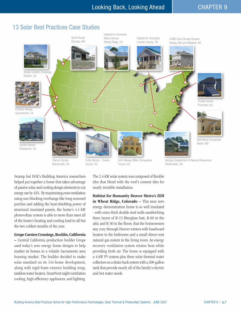
Building America Best Practices Series for High-Performance Technologies: Solar Thermal & Photovoltaic Systems - JUNE 2007 CHAPTER 9 / p.7
Looking Back, Looking Ahead CHAPTER 9
Swamp but DOE’s Building America researchers helped put together a home that takes advantage of passive solar and cooling design elements to cut energy use by 43%. By maximizing cross ventilation using sun-blocking overhangs like long screened porches and adding the heat-shielding power of structural insulated panels, the home’s 4.1-kW photovoltaic system is able to more than meet all of the home’s heating and cooling load in all but the two coldest months of the year.
Grupe Carsten Crossings, Rocklin, California – Central California production builder Grupe used today’s zero energy home designs to help market its homes in a volatile Sacramento area housing market. The builder decided to make solar standard on its 144-home development, along with rigid foam exterior building wrap, tankless water heaters, SmartVent night ventilation cooling, high-efficiency appliances, and lighting.
The 2.4-kW solar system was composed of flexible tiles that blend with the roof’s cement tiles for nearly invisible installation.
Habitat for Humanity Denver Metro’s ZEH in Wheat Ridge, Colorado – This near zero energy demonstration home is so well insulated - with extra thick double stud walls sandwiching three layers of R-13 fiberglass batt, R-60 in the attic and R-30 in the floors, that the homeowners stay cozy through Denver winters with baseboard heaters in the bedrooms and a small direct-vent natural gas system in the living room. An energy recovery ventilation system retains heat while providing fresh air. The home is equipped with a 4-kW PV system plus three solar thermal water collectors on a drain-back system with a 200-gallon tank that provide nearly all of the family’s electric and hot water needs.
13 Solar Best Practices Case Studies
Tindall HomesPrinceton, NJ
Bob Ward CompaniesBelAir, MD
Georgia Department of Natural Resources Okefenokee, GA
Habitat for Humanity Louden County, TN
Pulte Homes - Civano Tucson, AZ
John Wesley Miller Companies Tucson, AZ
Clarum Homes Watsonville, CA
Centex Homes Pleasanton, CA
Premier Homes Sacramento, CA
Grupe-Carsten Crossings Rocklin, CA
Garst HouseOlympia, WA
Habitat for Humanity Metro Denver Wheat Ridge, CO
CARB Cold Climate Houses Hadley, MA and Madison, WI
p.8 / CHAPTER 9 Building America Best Practices Series for High-Performance Technologies: Solar Thermal & Photovoltaic Systems - JUNE 2007
Looking Back, Looking Ahead CHAPTER 9
Habitat for Humanity Loudon County’s Five Test Homes in Tennessee – Loudon County’s Habitat for Humanity affiliate teamed with DOE’s Oak Ridge National Laboratory to build five near zero energy homes. The Lab has done extensive energy analysis on the houses, each of which has a different mix of energy-efficiency features including structural insulated panel walls and roofs, geothermal or air-to-air heat pumps, metal roofs, and 2 or 2.2 kW photovoltaic systems. Volunteer labor showed that energy-efficiency measures like draft-stopping and air sealing aren’t hard to learn. Total utility bills range from $0.30 to $1.00 per day.
John Wesley Miller Companies’ Armory Park del Sol in Tucson, Arizona – This southwestern style development includes rooftop solar panels for an integrated solar water heater and a 1.5-kW photovoltaic power system standard on each of its 99 units. Steel-reinforced masonry walls with rigid insulation under a three-coat stucco finish, R-38 ceiling insulation, and low-emissivity dual-pane windows ensure a tight thermal envelope and high-efficiency appliances and ducts in conditioned space help reduce energy usage.
Premier Homes Premier Gardens in Sacramento, California – Similarly sized and priced neighborhoods in a Sacramento subdivision provided an interesting test bed for zero energy homes. Premier Homes’ development outshone its neighbor with average annual utility bills of about $400 compared to $800 for the neighbor-ing Energy Star homes and $1000+ for standard construction homes. 2-kW PV systems and rigid foam exterior house wrap, well insulated ducts, and high-efficiency appliances, windows, and lighting made the difference.
Pulte Homes’ Civano Neighborhoods 2, 3, and 4, in Tucson, Arizona – When huge production builder Pulte Homes took over as master developer of neighborhoods 2, 3 and 4 of the Civano development near Tucson, it agreed to the energy efficiency, solar, and sustainability requirements
of the “new urbanist” planned community. Using Building America research and lessons learned from other builders of Civano Neighborhood 1, Pulte selected a workable combination of active closed-loop solar thermal water heaters to meet the 5% solar requirement and an efficiency package it calls Pulte platinum to meet the energy savings requirement of 50% over local code. The package includes “cathedralized” application of blown insulation along the roof line of the attic to provide conditioned space for the ducts and air handler as well as air leakage testing, high-performance closed-combustion gas appliances, and use of a drainage plane, flashing, and other water manage-ment details to provide superior energy performance as well as safety and durability for the 1200 to 1500 homes Pulte plans to build.
The Garst House near Olympia, Washington – It may be hard to believe solar can work in the cloudy, damp Pacific Northwest but home owner Sam Garst teamed with Building America and a building science-minded builder and architect to showcase just how green you can get in the evergreen state. The house sports a 4.5-kW photo-voltaic system, radiant heat and hot water from a ground source heat pump, advanced framing, a foam-insulated slab foundation, and Icynene spray wall and ceiling insulation, together with other green features like a greenhouse for passive solar heat, a rainwater cistern, construction recycling, fly-ash concrete, low VOC finishes, and bamboo and recycled tire flooring.
Tindall Homes’ Legends at Mansfield in Columbus, New Jersey – New Jersey builder Mark Bergman pioneered the first all-solar development of market-rate homes in New Jersey, with 39 homes built to be at least 60% more efficient than code. The heavily insulated, tightly sealed homes use energy-efficient appliances and lighting to cut energy use. To ensure maximum solar gain for his 2.64-kW photovoltaic systems, he located the panels on detached garden sheds that could be located anywhere on the lots for ideal orientation to the sun.

Building America Best Practices Series for High-Performance Technologies: Solar Thermal & Photovoltaic Systems - JUNE 2007 CHAPTER 9 / p.9
Looking Back, Looking Ahead CHAPTER 9
Resources and References
Butti, Ken and John Perlin. 1980. Golden Thread: Twentyfive Hundred Years of Solar Architecture and Technology. Cheshire Books. Palo Alto, CA. Excerpt posted on www.californiasolarcenter.org/history_solarthermal.html. Accessed on 15 May 2006.
DOE’s Energy Efficiency and Renewable Energy’s Solar Decathlon www.eere.energy.gov/solar_decathlon/
Green, Constance McLaughlin and Milton Lomask. 1970. Vanguard: A History. NASA SP-4202. National Aeronautics and Space Administration. Washington, D.C. available at www.hq.nasa.gov/office/pao/History/SP-4202/cover.htm. Accessed on 15 May 2006.
Lane, Tom. 2004. Solar Hot Water Systems: Lessons Learned 1977 to Today. Energy Conservation Services of North Florida, Inc. Gainesville, FL.
National Air and Space Administration www.nasa.gov
National Air and Space Museum www.nasm.si.edu/research/dsh/artifacts/SS-vanguard.htm
Perlin, John. 1999. From Space to Earth – the Story of Solar Electricity. Excerpts posted on www.californiasolarcenter.org/history_pv.html. Accessed on 15 May 2006.
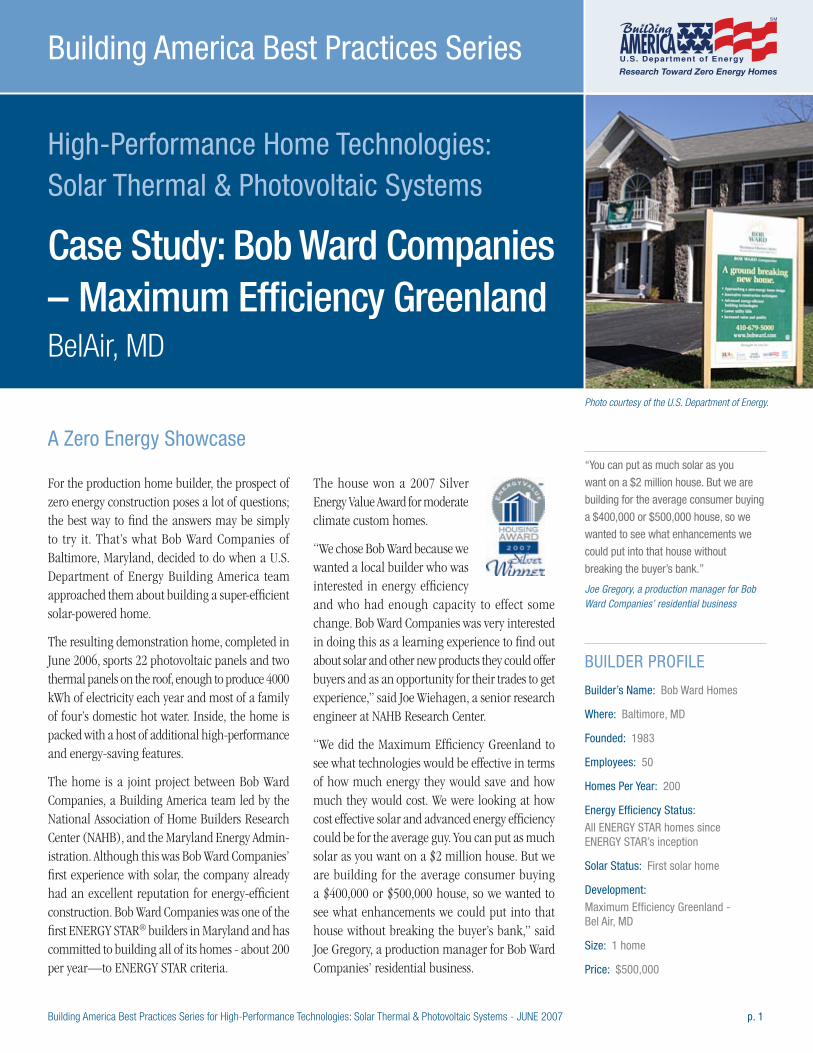
Building America Best Practices Series for High-Performance Technologies: Solar Thermal & Photovoltaic Systems - JUNE 2007 p. 1
High-Performance Home Technologies: Solar Thermal & Photovoltaic Systems
Case Study: Bob Ward Companies – Maximum Efficiency Greenland
BelAir, MD
Building America Best Practices Series
For the production home builder, the prospect of zero energy construction poses a lot of questions; the best way to find the answers may be simply to try it. That’s what Bob Ward Companies of Baltimore, Maryland, decided to do when a U.S. Department of Energy Building America team approached them about building a super-efficient solar-powered home.
The resulting demonstration home, completed in June 2006, sports 22 photovoltaic panels and two thermal panels on the roof, enough to produce 4000 kWh of electricity each year and most of a family of four’s domestic hot water. Inside, the home is packed with a host of additional high-performance and energy-saving features.
The home is a joint project between Bob Ward Companies, a Building America team led by the National Association of Home Builders Research Center (NAHB), and the Maryland Energy Admin-istration. Although this was Bob Ward Companies’ first experience with solar, the company already had an excellent reputation for energy-efficient construction. Bob Ward Companies was one of the first ENERGY STAR® builders in Maryland and has committed to building all of its homes - about 200 per year—to ENERGY STAR criteria.
The house won a 2007 Silver Energy Value Award for moderate climate custom homes.
“We chose Bob Ward because we wanted a local builder who was interested in energy efficiency and who had enough capacity to effect some change. Bob Ward Companies was very interested in doing this as a learning experience to find out about solar and other new products they could offer buyers and as an opportunity for their trades to get experience,” said Joe Wiehagen, a senior research engineer at NAHB Research Center.
“We did the Maximum Efficiency Greenland to see what technologies would be effective in terms of how much energy they would save and how much they would cost. We were looking at how cost effective solar and advanced energy efficiency could be for the average guy. You can put as much solar as you want on a $2 million house. But we are building for the average consumer buying a $400,000 or $500,000 house, so we wanted to see what enhancements we could put into that house without breaking the buyer’s bank,” said Joe Gregory, a production manager for Bob Ward Companies’ residential business.
“You can put as much solar as you
want on a $2 million house. But we are
building for the average consumer buying
a $400,000 or $500,000 house, so we
wanted to see what enhancements we
could put into that house without
breaking the buyer’s bank.” Joe Gregory, a production manager for Bob Ward Companies’ residential business
BUILDER PROFILE
Builder’s Name: Bob Ward Homes
Where: Baltimore, MD
Founded: 1983
Employees: 50
Homes Per Year: 200
Energy Efficiency Status:
All ENERGY STAR homes since ENERGY STAR’s inception
Solar Status: First solar home
Development:
Maximum Efficiency Greenland - Bel Air, MD
Size: 1 home
Price: $500,000
A Zero Energy Showcase
Photo courtesy of the U.S. Department of Energy.
p. 2 Building America Best Practices Series for High-Performance Technologies: Solar Thermal & Photovoltaic Systems - JUNE 2007
Bob Ward Companies – Maximum Efficiency GreenlandCASE STUDY
The NAHB Research Center conducted energy-effi-ciency testing during construction and is conducting performance monitoring of the energy use, solar PV, and hot water production, as well as the heating, cooling, and ventilation systems for a full year before the home is sold and occupied. NAHB Research Center also helped with consumer education materi-als like posters and brochures explaining the solar systems and energy-efficiency measures.
“We want to get as much educational value out of the house as we can this year, while the displays are set up and we are doing monitoring,” said Gregory. “We did two open houses. The first was at rough-in stage, the second was at the final construction stage in June. We hosted a tour for the local green building network in July 2006 and another tour in September for the technical high school and community college building and energy efficiency programs. We have several displays set up throughout the house to tell people what’s inside the walls and about the mechanical systems and the extra insulation. Several local builders have come by to look at the house during construction and since we’ve completed it.”
“The Maximum Efficiency Greenland model was a research house for us and for other builders in the area. We are hoping to get a few more to jump on board with the energy-efficiency improvements,” said Gregory. “You have to prove to builders and to home buyers that it can be done, and that it’s worthwhile. We will start offering solar as an optional upgrade after we get all of the data from NAHB Research Center. We want to come up with cost savings to show potential buyers.”
“We used one of our standard house designs, not a special design, in a development where we have four lots. We didn’t have to do anything special to the lot, we just made a minor adjustment in the home’s orientation on the lot to improve the roof’s solar gain,” said Gregory. “One thing we wanted to know is whether we can make solar work as an option here on the East Coast where a builder often has to submit plans two or three years before they build; at that stage you won’t know which home buyers are going to ask for solar,” he concluded.
Solar SystemThe 3-kW roof-mounted PV system consists of 22 63-inch by 31-inch Integra modules manufactured by BP Solar. “The DC output of the system is rated at 3850 watts and it may hit 3 kilowatts of AC in full sun,” said Wiehagen. “The panels rise no more than two inches above the roof’s surface, a very low profile for a system not integrated into the roofing material,” Wiehagen noted. The panels also use a unique bracket that can be bolted to the roof’s sheathing instead of into the trusses. Each bracket can accommodate two panels if the panels are butted against each other. “It was a pretty quick installation,” said Wiehagen. “The installers installed one panel every 15 minutes.”
The NAHB Research Center helped the builder locate an installer. They chose Aurora Energy LLC, a solar contractor that has worked throughout the Mid-Atlantic states since 1994 installing PV systems for homes, businesses, and government clients including the White House and the Pentagon.
The house also features two roof-top 29-sq-ft Stiebel-Eltron thermal collectors. Copper tubing transports the heated fluid from the roof to an 80-gallon storage tank in the home’s basement. The closed loop system contains antifreeze so the system will operate in all seasons. The solar thermal system preheats the water, greatly reducing demand on the home’s Seisco electric instant-on water heater.
“We used our regular electricians and plumbers to work with Aurora Energy,” said Gregory. “The PV installers are not permitted to go into the panel box. The electrician has to do the cabling from the inverter to the panel box. Our electrician ran the cables into the attic so Aurora could make the connection,” Gregory added.
Energy Efficiency MeasuresSolar power was just one of the building innovations that Bob Ward was interested in trying out. For the home’s full basement with nine-foot ceilings, they tested insulated concrete wall panels made by Superior Walls. The wall and foundation system consists of a 2-inch layer of high-density concrete
KEY FEATURES
3kW roof-mounted photovoltaic system
Two solar hot water panels installed
on roof, to preheat 80-gallon
hot water tank
Superior Wall Foundation - prefabricated
basement wall panels of 2-inch layer of
high-density concrete, steel-reinforced
concrete studs, and 2-inch layer of solid
foam insulation in between for R-12
wall. R-19 fiberglass bat can be added
between studs.
2x4 16-inch on center upper walls with
optimum value engineering framing
techniques: 3-stud corners, ladder
nailers where interior partitions intersect
exterior walls, insulated headers
Thermal ply sheathing with a
1-inch layer of rigid foam insulation
taped at joints
R22 blown fiberglass in walls
R50 blown fiberglass in ceiling
Ducts in conditioned space
Cross-over vents for all bedrooms
Passive fresh air intake to return air
filter; auto-on cycling whole house
and bathroom exhaust fans
Air source heat pump, 9.3 HSPF,
19 SEER air conditioner
High-performance low-e
argon-filled windows
ENERGY STAR lighting in 90% of
fixtures; ENERGY STAR appliances
Significant air sealing package:
foam-sealed band joists, top and
bottom plates, windows, and wiring
and plumbing penetrations
Blower door and duct blaster tests
conducted by NAHB
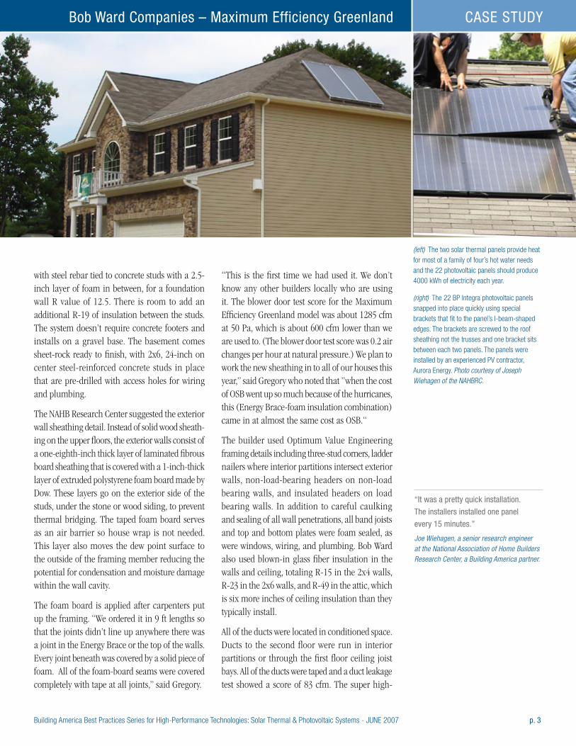
Building America Best Practices Series for High-Performance Technologies: Solar Thermal & Photovoltaic Systems - JUNE 2007 p. 3
Bob Ward Companies – Maximum Efficiency Greenland CASE STUDY
with steel rebar tied to concrete studs with a 2.5-inch layer of foam in between, for a foundation wall R value of 12.5. There is room to add an additional R-19 of insulation between the studs. The system doesn’t require concrete footers and installs on a gravel base. The basement comes sheet-rock ready to finish, with 2x6, 24-inch on center steel-reinforced concrete studs in place that are pre-drilled with access holes for wiring and plumbing.
The NAHB Research Center suggested the exterior wall sheathing detail. Instead of solid wood sheath-ing on the upper floors, the exterior walls consist of a one-eighth-inch thick layer of laminated fibrous board sheathing that is covered with a 1-inch-thick layer of extruded polystyrene foam board made by Dow. These layers go on the exterior side of the studs, under the stone or wood siding, to prevent thermal bridging. The taped foam board serves as an air barrier so house wrap is not needed. This layer also moves the dew point surface to the outside of the framing member reducing the potential for condensation and moisture damage within the wall cavity.
The foam board is applied after carpenters put up the framing. “We ordered it in 9 ft lengths so that the joints didn’t line up anywhere there was a joint in the Energy Brace or the top of the walls. Every joint beneath was covered by a solid piece of foam. All of the foam-board seams were covered completely with tape at all joints,” said Gregory.
“This is the first time we had used it. We don’t know any other builders locally who are using it. The blower door test score for the Maximum Efficiency Greenland model was about 1285 cfm at 50 Pa, which is about 600 cfm lower than we are used to. (The blower door test score was 0.2 air changes per hour at natural pressure.) We plan to work the new sheathing in to all of our houses this year,” said Gregory who noted that ”when the cost of OSB went up so much because of the hurricanes, this (Energy Brace-foam insulation combination) came in at almost the same cost as OSB.“
The builder used Optimum Value Engineering framing details including three-stud corners, ladder nailers where interior partitions intersect exterior walls, non-load-bearing headers on non-load bearing walls, and insulated headers on load bearing walls. In addition to careful caulking and sealing of all wall penetrations, all band joists and top and bottom plates were foam sealed, as were windows, wiring, and plumbing. Bob Ward also used blown-in glass fiber insulation in the walls and ceiling, totaling R-15 in the 2x4 walls, R-23 in the 2x6 walls, and R-49 in the attic, which is six more inches of ceiling insulation than they typically install.
All of the ducts were located in conditioned space. Ducts to the second floor were run in interior partitions or through the first floor ceiling joist bays. All of the ducts were taped and a duct leakage test showed a score of 83 cfm. The super high-
(left) The two solar thermal panels provide heat for most of a family of four’s hot water needs and the 22 photovoltaic panels should produce 4000 kWh of electricity each year.
(right) The 22 BP Integra photovoltaic panels snapped into place quickly using special brackets that fit to the panel’s I-beam-shaped edges. The brackets are screwed to the roof sheathing not the trusses and one bracket sits between each two panels. The panels were installed by an experienced PV contractor, Aurora Energy. Photo courtesy of Joseph Wiehagen of the NAHBRC.
“It was a pretty quick installation.
The installers installed one panel
every 15 minutes.” Joe Wiehagen, a senior research engineer at the National Association of Home Builders Research Center, a Building America partner.
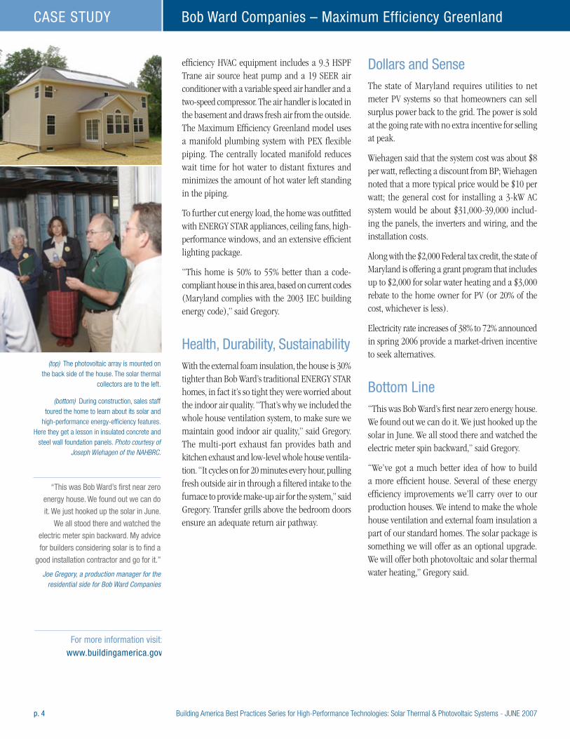
p. 4 Building America Best Practices Series for High-Performance Technologies: Solar Thermal & Photovoltaic Systems - JUNE 2007
Bob Ward Companies – Maximum Efficiency GreenlandCASE STUDY
efficiency HVAC equipment includes a 9.3 HSPF Trane air source heat pump and a 19 SEER air conditioner with a variable speed air handler and a two-speed compressor. The air handler is located in the basement and draws fresh air from the outside. The Maximum Efficiency Greenland model uses a manifold plumbing system with PEX flexible piping. The centrally located manifold reduces wait time for hot water to distant fixtures and minimizes the amount of hot water left standing in the piping.
To further cut energy load, the home was outfitted with ENERGY STAR appliances, ceiling fans, high-performance windows, and an extensive efficient lighting package.
“This home is 50% to 55% better than a code-compliant house in this area, based on current codes (Maryland complies with the 2003 IEC building energy code),” said Gregory.
Health, Durability, SustainabilityWith the external foam insulation, the house is 30% tighter than Bob Ward’s traditional ENERGY STAR homes, in fact it’s so tight they were worried about the indoor air quality. “That’s why we included the whole house ventilation system, to make sure we maintain good indoor air quality,” said Gregory. The multi-port exhaust fan provides bath and kitchen exhaust and low-level whole house ventila-tion. “It cycles on for 20 minutes every hour, pulling fresh outside air in through a filtered intake to the furnace to provide make-up air for the system,” said Gregory. Transfer grills above the bedroom doors ensure an adequate return air pathway.
Dollars and SenseThe state of Maryland requires utilities to net meter PV systems so that homeowners can sell surplus power back to the grid. The power is sold at the going rate with no extra incentive for selling at peak.
Wiehagen said that the system cost was about $8 per watt, reflecting a discount from BP; Wiehagen noted that a more typical price would be $10 per watt; the general cost for installing a 3-kW AC system would be about $31,000-39,000 includ-ing the panels, the inverters and wiring, and the installation costs.
Along with the $2,000 Federal tax credit, the state of Maryland is offering a grant program that includes up to $2,000 for solar water heating and a $3,000 rebate to the home owner for PV (or 20% of the cost, whichever is less).
Electricity rate increases of 38% to 72% announced in spring 2006 provide a market-driven incentive to seek alternatives.
Bottom Line“This was Bob Ward’s first near zero energy house. We found out we can do it. We just hooked up the solar in June. We all stood there and watched the electric meter spin backward,” said Gregory.
“We’ve got a much better idea of how to build a more efficient house. Several of these energy efficiency improvements we’ll carry over to our production houses. We intend to make the whole house ventilation and external foam insulation a part of our standard homes. The solar package is something we will offer as an optional upgrade.We will offer both photovoltaic and solar thermal water heating,” Gregory said.
(top) The photovoltaic array is mounted on the back side of the house. The solar thermal
collectors are to the left.
(bottom) During construction, sales staff toured the home to learn about its solar and
high-performance energy-efficiency features. Here they get a lesson in insulated concrete and
steel wall foundation panels. Photo courtesy of Joseph Wiehagen of the NAHBRC.
“This was Bob Ward’s first near zero
energy house. We found out we can do
it. We just hooked up the solar in June.
We all stood there and watched the
electric meter spin backward. My advice
for builders considering solar is to find a
good installation contractor and go for it.” Joe Gregory, a production manager for the
residential side for Bob Ward Companies
For more information visit: www.buildingamerica.gov
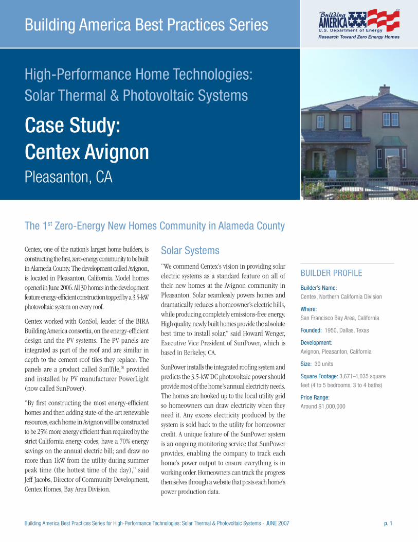
Building America Best Practices Series for High-Performance Technologies: Solar Thermal & Photovoltaic Systems - JUNE 2007 p. 1
High-Performance Home Technologies: Solar Thermal & Photovoltaic Systems
Case Study: Centex Avignon Pleasanton, CA
Building America Best Practices Series
Centex, one of the nation’s largest home builders, is constructing the first, zero-energy community to be built in Alameda County. The development called Avignon, is located in Pleasanton, California. Model homes opened in June 2006. All 30 homes in the development feature energy-efficient construction topped by a 3.5-kW photovoltaic system on every roof.
Centex worked with ConSol, leader of the BIRA Building America consortia, on the energy-efficient design and the PV systems. The PV panels are integrated as part of the roof and are similar in depth to the cement roof tiles they replace. The panels are a product called SunTile,® provided and installed by PV manufacturer PowerLight (now called SunPower).
“By first constructing the most energy-efficient homes and then adding state-of-the-art renewable resources, each home in Avignon will be constructed to be 25% more energy efficient than required by the strict California energy codes; have a 70% energy savings on the annual electric bill; and draw no more than 1kW from the utility during summer peak time (the hottest time of the day),” said Jeff Jacobs, Director of Community Development, Centex Homes, Bay Area Division.
Solar Systems“We commend Centex’s vision in providing solar electric systems as a standard feature on all of their new homes at the Avignon community in Pleasanton. Solar seamlessly powers homes and dramatically reduces a homeowner’s electric bills, while producing completely emissions-free energy. High quality, newly built homes provide the absolute best time to install solar,” said Howard Wenger, Executive Vice President of SunPower, which is based in Berkeley, CA.
SunPower installs the integrated roofing system and predicts the 3.5-kW DC photovoltaic power should provide most of the home’s annual electricity needs. The homes are hooked up to the local utility grid so homeowners can draw electricity when they need it. Any excess electricity produced by the system is sold back to the utility for homeowner credit. A unique feature of the SunPower system is an ongoing monitoring service that SunPower provides, enabling the company to track each home’s power output to ensure everything is in working order. Homeowners can track the progress themselves through a website that posts each home’s power production data.
BUILDER PROFILE
Builder’s Name:
Centex, Northern California Division
Where:
San Francisco Bay Area, California
Founded: 1950, Dallas, Texas
Development:
Avignon, Pleasanton, California
Size: 30 units
Square Footage: 3,671-4,035 square
feet (4 to 5 bedrooms, 3 to 4 baths)
Price Range:
Around $1,000,000
The 1st Zero-Energy New Homes Community in Alameda County
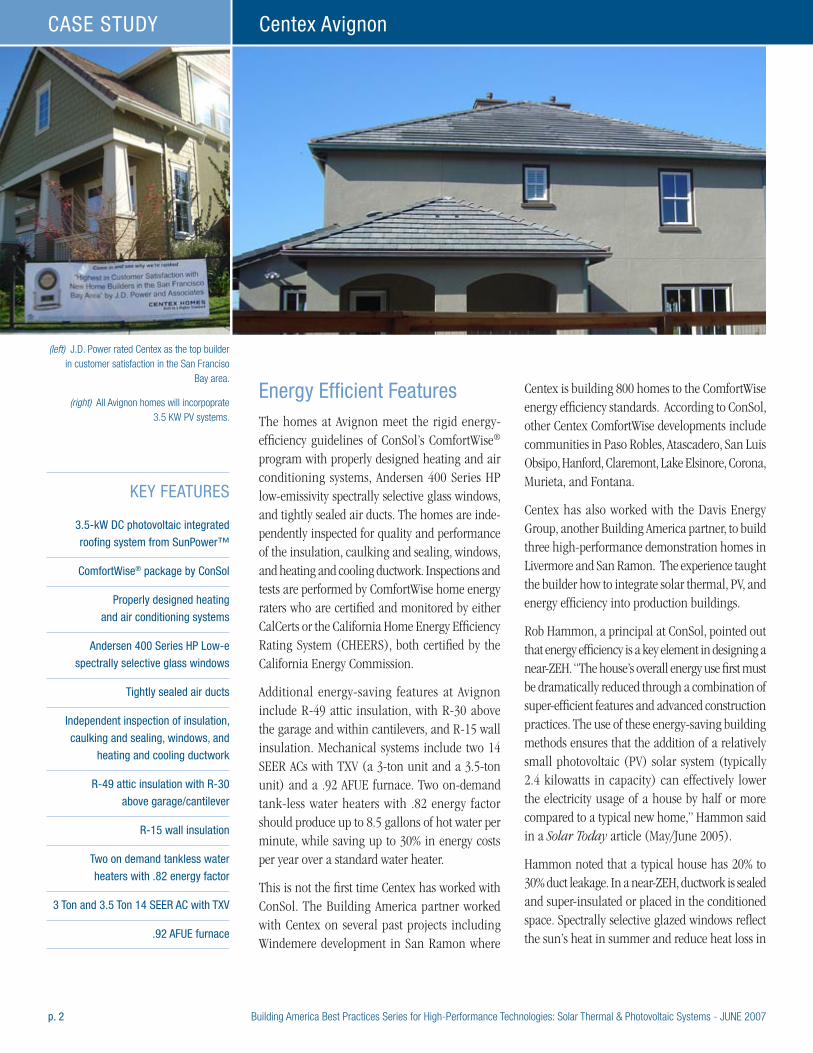
p. 2 Building America Best Practices Series for High-Performance Technologies: Solar Thermal & Photovoltaic Systems - JUNE 2007
Centex AvignonCASE STUDY
Energy Efficient FeaturesThe homes at Avignon meet the rigid energy-efficiency guidelines of ConSol’s ComfortWise® program with properly designed heating and air conditioning systems, Andersen 400 Series HP low-emissivity spectrally selective glass windows, and tightly sealed air ducts. The homes are inde-pendently inspected for quality and performance of the insulation, caulking and sealing, windows, and heating and cooling ductwork. Inspections and tests are performed by ComfortWise home energy raters who are certified and monitored by either CalCerts or the California Home Energy Efficiency Rating System (CHEERS), both certified by the California Energy Commission.
Additional energy-saving features at Avignon include R-49 attic insulation, with R-30 above the garage and within cantilevers, and R-15 wall insulation. Mechanical systems include two 14 SEER ACs with TXV (a 3-ton unit and a 3.5-ton unit) and a .92 AFUE furnace. Two on-demand tank-less water heaters with .82 energy factor should produce up to 8.5 gallons of hot water per minute, while saving up to 30% in energy costs per year over a standard water heater.
This is not the first time Centex has worked with ConSol. The Building America partner worked with Centex on several past projects including Windemere development in San Ramon where
Centex is building 800 homes to the ComfortWise energy efficiency standards. According to ConSol, other Centex ComfortWise developments include communities in Paso Robles, Atascadero, San Luis Obsipo, Hanford, Claremont, Lake Elsinore, Corona, Murieta, and Fontana.
Centex has also worked with the Davis Energy Group, another Building America partner, to build three high-performance demonstration homes in Livermore and San Ramon. The experience taught the builder how to integrate solar thermal, PV, and energy efficiency into production buildings.
Rob Hammon, a principal at ConSol, pointed out that energy efficiency is a key element in designing a near-ZEH. “The house’s overall energy use first must be dramatically reduced through a combination of super-efficient features and advanced construction practices. The use of these energy-saving building methods ensures that the addition of a relatively small photovoltaic (PV) solar system (typically 2.4 kilowatts in capacity) can effectively lower the electricity usage of a house by half or more compared to a typical new home,” Hammon said in a Solar Today article (May/June 2005).
Hammon noted that a typical house has 20% to 30% duct leakage. In a near-ZEH, ductwork is sealed and super-insulated or placed in the conditioned space. Spectrally selective glazed windows reflect the sun’s heat in summer and reduce heat loss in
KEY FEATURES
3.5-kW DC photovoltaic integrated
roofing system from SunPower™
ComfortWise® package by ConSol
Properly designed heating
and air conditioning systems
Andersen 400 Series HP Low-e
spectrally selective glass windows
Tightly sealed air ducts
Independent inspection of insulation,
caulking and sealing, windows, and
heating and cooling ductwork
R-49 attic insulation with R-30
above garage/cantilever
R-15 wall insulation
Two on demand tankless water
heaters with .82 energy factor
3 Ton and 3.5 Ton 14 SEER AC with TxV
.92 AFUE furnace
(left) J.D. Power rated Centex as the top builder in customer satisfaction in the San Franciso
Bay area.
(right) All Avignon homes will incorpoprate 3.5 KW PV systems.

Building America Best Practices Series for High-Performance Technologies: Solar Thermal & Photovoltaic Systems - JUNE 2007 p. 3
Centex Avignon CASE STUDY
winter. Carefully designed HVAC systems account for bends and turns in ductwork, register locations, duct length, connections and airflow. Other ways to “tighten up” residential energy consumption include improved ceiling and wall insulation, energy-efficient appliances and the use of fluores-cent lighting. “All of these efforts are combined in a whole-house approach to designing and building the ZEH,” said Hammon.
Dollars and SenseIncentives are available to builders and to home owners. In January 2006, the California Public Utili-ties Commission (CPUC) adopted a program–the California Solar Initiative (CSI)–to provide more than $3 billion in incentives for solar projects with the objective of providing 3,000 MW of solar capacity by 2017 from residential and commercial projects combined. Homeowners will receive $2.50/Watt AC for residential systems, with the incentives awarded as a one-time, up-front payment based on expected system performance. Several counties offer incentives to builders including free techni-cal advice and waiving of fees on solar projects; some counties offer rebates to homeowners on solar equipment.
There is also the federal $2,000 tax credit for homeowners who purchase solar electric and solar water heating systems as well as a $500 tax credit for those who purchase energy-efficient
equipment like furnaces, air conditioners and water heaters. Also, many utilities in California offer a rebate for energy-efficient construction, usually $500 per house.
“We are typically spending $1,000 to $1500 per house to get to 20% above code. But we can market these homes at a premium,” said Jacobs. Centex predicts homeowner energy bills at Avignon will be reduced by up to 70% each year.
“I don’t expect any builder to lose money,” said Jacobs. “You may have a desire to be a good steward of the environment but you also have to be responsive to your stockholders. There are strong environmental and societal reasons for building energy-efficient homes. But strong, sustainable building practices also help a builder differentiate themselves in a competitive marketplace, while still keeping focused on the bottom line. The American public has proven over and over that they are willing to pay more for it (energy-efficient construction).”
“We need to educate the buyer. If you are building houses and you start including photovoltaics, and tankless water heaters, and high-performance construction, your buyers are going to enjoy living in those homes because of lower operating costs, increased comfort, etc. We just need to educate homeowners to see what they are getting. The message they need to hear is ‘You pay more but you get more,’” said Jacobs.
About Centex Homes
Dallas-based Centex Homes (www.centexhomes.com) is one of the nation’s leading home builders, operating in more than 90 U.S. markets in 25 states and delivering 33,387 homes in the United States in 2005. The company is a subsidiary of Centex Corporation (NYSE: CTX), a Fortune 250 company. Centex Corporation (www.centex.com), founded in Dallas in 1950, is one of the nation’s premier companies in home building, financial services, home services and commercial contracting. Centex ranks No. 1 in its industry on FORTUNE magazine’s 2005 list of “America’s Most Admired Companies.” Centex has been ranked “highest in customer satisfaction with new home builders in the San Francisco Bay Area” by JD Power and Associates in both 2005 and 2006.
About SunPower
SunPower Corporation (formerly known
as PowerLight) is a leading global provider
of grid-connected solar electric power
systems. SunPower’s turnkey solutions for
commercial, government and residential
customers feature a full line of proprietary
solar products and technologies designed
to optimize energy output and project
economics. Recognized by Inc. Magazine
for five consecutive years as one of
the 500 fastest growing privately held
companies, SunPower designs, builds and
operates many of the largest solar electric
systems in North America and Europe. For
more information about SunPower and its
products and services, please visit
www.sunpower.com.
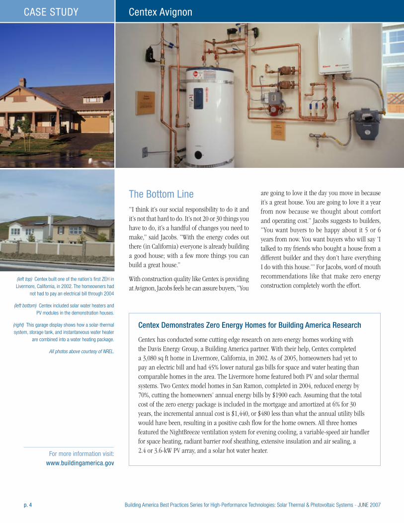
p. 4 Building America Best Practices Series for High-Performance Technologies: Solar Thermal & Photovoltaic Systems - JUNE 2007
Centex AvignonCASE STUDY
The Bottom Line“I think it’s our social responsibility to do it and it’s not that hard to do. It’s not 20 or 30 things you have to do, it’s a handful of changes you need to make,” said Jacobs. “With the energy codes out there (in California) everyone is already building a good house; with a few more things you can build a great house.”
With construction quality like Centex is providing at Avignon, Jacobs feels he can assure buyers, “You
are going to love it the day you move in because it’s a great house. You are going to love it a year from now because we thought about comfort and operating cost.” Jacobs suggests to builders, “You want buyers to be happy about it 5 or 6 years from now. You want buyers who will say ‘I talked to my friends who bought a house from a different builder and they don’t have everything I do with this house.’” For Jacobs, word of mouth recommendations like that make zero energy construction completely worth the effort.
(left top) Centex built one of the nation’s first ZEH in Livermore, California, in 2002. The homeowners had
not had to pay an electrical bill through 2004
(left bottom) Centex included solar water heaters and PV modules in the demonstration houses.
(right) This garage display shows how a solar-thermal system, storage tank, and instantaneous water heater
are combined into a water heating package.
All photos above courtesy of NREL.
Centex Demonstrates Zero Energy Homes for Building America Research
Centex has conducted some cutting edge research on zero energy homes working with the Davis Energy Group, a Building America partner. With their help, Centex completed a 3,080 sq ft home in Livermore, California, in 2002. As of 2005, homeowners had yet to pay an electric bill and had 45% lower natural gas bills for space and water heating than comparable homes in the area. The Livermore home featured both PV and solar thermal systems. Two Centex model homes in San Ramon, completed in 2004, reduced energy by 70%, cutting the homeowners’ annual energy bills by $1900 each. Assuming that the total cost of the zero energy package is included in the mortgage and amortized at 6% for 30 years, the incremental annual cost is $1,440, or $480 less than what the annual utility bills would have been, resulting in a positive cash flow for the home owners. All three homes featured the NightBreeze ventilation system for evening cooling, a variable-speed air handler for space heating, radiant barrier roof sheathing, extensive insulation and air sealing, a 2.4 or 3.6-kW PV array, and a solar hot water heater. For more information visit:
www.buildingamerica.gov
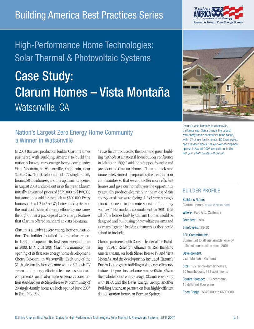
Building America Best Practices Series for High-Performance Technologies: Solar Thermal & Photovoltaic Systems -JUNE 2007 p. 1
High-Performance Home Technologies: Solar Thermal & Photovoltaic Systems
Case Study: Clarum Homes – Vista Montaña Watsonville, CA
Building America Best Practices Series
In 2003 Bay area production builder Clarum Homes partnered with Building America to build the nation’s largest zero-energy home community, Vista Montaña, in Watsonville, California, near Santa Cruz. The development of 177 single-family homes, 80 townhouses, and 132 apartments opened in August 2003 and sold out in its first year. Clarum initially advertised prices of $379,000 to $499,000 but some units sold for as much as $600,000. Every home sports a 1.2 to 2.4 kW photovoltaic system on the roof and a slew of energy-efficiency measures throughout in a package of zero energy features that Clarum offered standard at Vista Montaña.
Clarum is a leader at zero energy home construc-tion. The builder installed its first solar system in 1999 and opened its first zero energy home in 2000. In August 2001 Clarum announced the opening of its first zero energy home development, Cherry Blossom, in Watsonville. Each one of the 31 single-family homes came with a 3.2-kwh PV system and energy efficient features as standard equipment. Clarum also made zero energy construc-tion standard on its Shorebreeze IV community of 20 single-family homes, which opened June 2003 in East Palo Alto.
“I was first introduced to the solar and green build-ing methods at a national homebuilder conference in Atlanta in 1999,” said John Suppes, founder and president of Clarum Homes. “I came back and immediately started incorporating the ideas into our communities so that we could offer more efficient homes and give our homebuyers the opportunity to actually produce electricity in the midst of this energy crisis we were facing. I feel very strongly about the need to promote sustainable energy sources.” He made a commitment in 2001 that all of the homes built by Clarum Homes would be designed and built using photovoltaic systems and as many “green” building features as they could afford to include.
Clarum partnered with ConSol, leader of the Build-ing Industry Research Alliance (BIRA) Building America team, on both Shore Breeze IV and Vista Montaña and the developments included Clarum’s Enviro-Home green building and energy-efficiency features designed to save homeowners 60% to 90% on their whole house energy usage. Clarum is working with BIRA and the Davis Energy Group, another Building American partner, on four highly efficient demonstration homes at Borrego Springs.
BUILDER PROFILE
Builder’s Name:
Clarum Homes www.clarum.com
Where: Palo Alto, California
Founded: 1994
Employees: 35-50
ZEH Commitment:
Committed to all sustainable, energy
efficient construction since 2001.
Development:
Vista Montaña, California
Size: 177 single-family homes,
80 townhouses, 132 apartments
Square footage: 3-5 bedrooms,
10 different floor plans
Price Range: $379,000 to $600,000
Nation’s Largest Zero Energy Home Community a Winner in Watsonville
Clarum’s Vista Montaña in Watsonville, California, near Santa Cruz, is the largest zero-energy home community in the nation, with 177 single-family homes, 80 townhouses, and 132 apartments. The all-solar development opened in August 2003 and sold out in the first year. Photo courtesy of Consol.
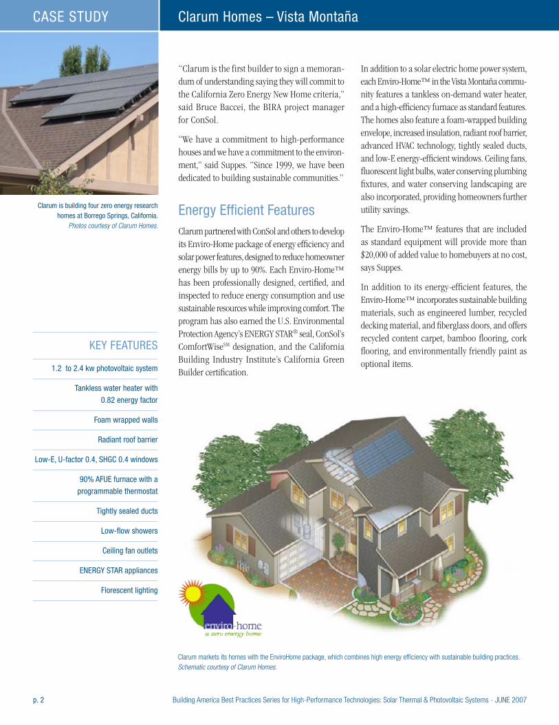
p. 2 Building America Best Practices Series for High-Performance Technologies: Solar Thermal & Photovoltaic Systems - JUNE 2007
Clarum Homes – Vista MontañaCASE STUDY
“Clarum is the first builder to sign a memoran-dum of understanding saying they will commit to the California Zero Energy New Home criteria,” said Bruce Baccei, the BIRA project manager for ConSol.
“We have a commitment to high-performance houses and we have a commitment to the environ-ment,” said Suppes. “Since 1999, we have been dedicated to building sustainable communities.”
Energy Efficient Features Clarum partnered with ConSol and others to develop its Enviro-Home package of energy efficiency and solar power features, designed to reduce homeowner energy bills by up to 90%. Each Enviro-Home™ has been professionally designed, certified, and inspected to reduce energy consumption and use sustainable resources while improving comfort. The program has also earned the U.S. Environmental Protection Agency’s ENERGY STAR® seal, ConSol’s ComfortWiseSM designation, and the California Building Industry Institute’s California Green Builder certification.
In addition to a solar electric home power system, each Enviro-Home™ in the Vista Montaña commu-nity features a tankless on-demand water heater, and a high-efficiency furnace as standard features. The homes also feature a foam-wrapped building envelope, increased insulation, radiant roof barrier, advanced HVAC technology, tightly sealed ducts, and low-E energy-efficient windows. Ceiling fans, fluorescent light bulbs, water conserving plumbing fixtures, and water conserving landscaping are also incorporated, providing homeowners further utility savings.
The Enviro-Home™ features that are included as standard equipment will provide more than $20,000 of added value to homebuyers at no cost, says Suppes.
In addition to its energy-efficient features, the Enviro-Home™ incorporates sustainable building materials, such as engineered lumber, recycled decking material, and fiberglass doors, and offers recycled content carpet, bamboo flooring, cork flooring, and environmentally friendly paint as optional items.
KEY FEATURES
1.2 to 2.4 kw photovoltaic system
Tankless water heater with
0.82 energy factor
Foam wrapped walls
Radiant roof barrier
Low-E, U-factor 0.4, SHGC 0.4 windows
90% AFUE furnace with a
programmable thermostat
Tightly sealed ducts
Low-flow showers
Ceiling fan outlets
ENERGY STAR appliances
Florescent lighting
Clarum markets its homes with the EnviroHome package, which combines high energy efficiency with sustainable building practices. Schematic courtesy of Clarum Homes.
Clarum is building four zero energy research homes at Borrego Springs, California.
Photos courtesy of Clarum Homes.

Building America Best Practices Series for High-Performance Technologies: Solar Thermal & Photovoltaic Systems - JUNE 2007 p. 3
Clarum Homes – Vista Montaña CASE STUDY
Clarum is building four zero energy research homes at Borrego Springs, California. Polystyrene slab edge insulation helps to carefully control heat gains and losses. Photos courtesy of Clarum Homes.
Extreme Heat Meets Extreme Cool
Showing the ingenuity that can pay big dividends for a production home builder, Clarum is branching out into the Anzo Borrego desert with four test homes that could help Clarum offer homes that beat the heat and high energy costs at a cost to Clarum that will still ensure profits as the Bay area builder reaches into hotter, drier locales.
Clarum partnered with Building America partners ConSol and the Davis Energy Group to build four super-efficient demonstration homes in Borrego Springs where temperatures routinely soar past 100 degrees F 6 months of the year.
“These demonstration homes in Borrego Springs provide an opportunity to try out new products that could be economically viable in the regular and affordable housing markets we serve,” explained Suppes.
The four homes use an identical floor plan sporting three bedrooms and three baths in 2,000 sq ft of living space and Clarum installed identical 3.2-kW Kyocera photovoltaic solar systems on each home. The PV panels mount to the standing seams of the homes’ metal roofs so there are no roof penetrations. The homes also have several energy-efficiency features in common including tankless water heaters, rigid polystyrene insulation around the foundation, and ENERGY STAR appliances and fluorescent lighting. Heat gain from the sun is kept to a minimum through use of a radiant roof barrier, low-emissivity windows, five-foot shade overhangs over the homes’ perimeters, and shade screens on the windows and doors of all four homes. But there are some unique differences between the homes, including three different kinds of exterior wall systems, three different cooling systems, and two kinds of space heating.
The demonstration project homes showcase two types of advanced wall systems – rigid foam insulated thermal mass concrete walls, in this case a Dow product called Styrofoam T-MASS, and structural insulated panels (SIPS), as well as 16-inch-on-center 2x6” lumber framing on one house for comparison.
The homes are equipped with three different cutting-edge cooling systems. Two of the homes feature Speakman OASys two-stage evaporative coolers; the third home features both a Freus water-cooled condenser (which cools indoor air as well as the floor) and a NightBreeze night ventilation cooling system; and the fourth home features a Lennox 20.5 SEER air conditioner. The cooling systems were designed to accommodate both the hot-dry conditions that prevail most of the summer and the hot-humid weather that accompanies the monsoon season in late summer. Three of the homes are also equipped with under-floor radiant heating.
Building America partner Davis Energy Group designed the heating and cooling systems for the homes, which were completed in May 2006. Davis is working with ConSol to monitor energy use through summer 2007 to collect two cooling season’s worth of data, one without occupants and one with. They hope to collect data on cost, construction schedule, production feasibility, energy efficiency, product lifecycles, embodied energy, and cost and energy savings. Clarum hopes at least one of the homes will show a 90% reduction in cooling energy.
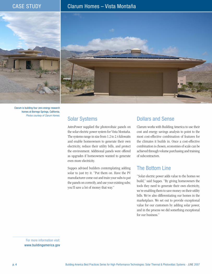
p. 4 Building America Best Practices Series for High-Performance Technologies: Solar Thermal & Photovoltaic Systems - JUNE 2007
Clarum Homes – Vista MontañaCASE STUDY
Solar SystemsAstroPower supplied the photovoltaic panels on the solar electric power system for Vista Montaña. The systems range in size from 1.2 to 2.4 kilowatts and enable homeowners to generate their own electricity, reduce their utility bills, and protect the environment. Additional panels were offered as upgrades if homeowners wanted to generate even more electricity.
Suppes advised builders contemplating adding solar to just try it. “Put them on. Have the PV manufacturer come out and train your subs to put the panels on correctly, and use your existing subs; you’ll save a lot of money that way.”
Dollars and SenseClarum works with Building America to use their cost and energy savings analysis to point to the most cost-effective combination of features for the climates it builds in. Once a cost-effective combination is chosen, economies of scale can be achieved through volume purchasing and training of subcontractors.
The Bottom Line“Solar electric power adds value to the homes we build,” said Suppes. “By giving homeowners the tools they need to generate their own electricity, we’re enabling them to save money on their utility bills. We’re also differentiating our homes in the marketplace. We set out to provide exceptional value for our customers by adding solar power, and in the process we did something exceptional for our business.”
For more information visit: www.buildingamerica.gov
Clarum is building four zero energy research homes at Borrego Springs, California.
Photos courtesy of Clarum Homes.
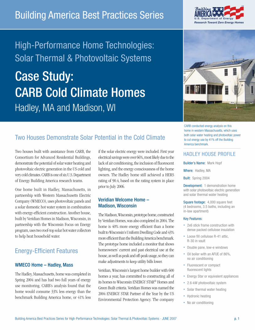
Building America Best Practices Series for High-Performance Technologies: Solar Thermal & Photovoltaic Systems - JUNE 2007 p. 1
High-Performance Home Technologies: Solar Thermal & Photovoltaic Systems
Case Study: CARB Cold Climate Homes Hadley, MA and Madison, WI
Building America Best Practices Series
Two houses built with assistance from CARB, the Consortium for Advanced Residential Buildings, demonstrate the potential of solar water heating and photovoltaic electric generation in the US cold and very cold climates. CARB is one of six U.S. Department of Energy Building America research teams.
One home built in Hadley, Massachusetts, in partnership with Western Massachusetts Electric Company (WMECO), uses photovoltaic panels and a solar domestic hot water system in combination with energy-efficient construction. Another house, built by Veridian Homes in Madison, Wisconsin, in partnership with the Wisconsin Focus on Energy program, uses two roof-top solar hot water collectors to help heat household water.
Energy-Efficient Features
WMECO Home – Hadley, Mass
The Hadley, Massachusetts, home was completed in Spring 2004 and has had two full years of energy use monitoring. CARB’s analysis found that the home would consume 33% less energy than the benchmark Building America home, or 41% less
if the solar electric energy were included. First year electrical savings were over 66%, most likely due to the lack of air conditioning, the inclusion of fluorescent lighting, and the energy consciousness of the home owners. The Hadley home still achieved a HERS rating of 90.4, based on the rating system in place prior to July 2006.
Veridian Welcome Home – Madison, Wisconsin
The Madison, Wisconsin, prototype home, constructed by Veridian Homes, was also completed in 2004. The home is 40% more energy efficient than a home built to Wisconsin’s Uniform Dwelling Code and 43% more efficient than the Building America benchmark. The prototype home included a monitor that shows homeowners’ current and past electrical use at the house, as well as peak and off-peak usage, so they can make adjustments to keep utility bills lower.
Veridian, Wisconsin’s largest home builder with 600 homes a year, has committed to constructing all of its homes to Wisconsin ENERGY STAR® Homes and Green Built criteria. Veridian Homes was named the 2004 ENERGY STAR Partner of the Year by the US Environmental Protection Agency. The company
HADLEY HOUSE PROFILE
Builder’s Name: Mark Hopf
Where: Hadley, MA
Built: Spring 2004
Development: 1 demonstration home with solar photovoltaic electric generation and solar thermal water heating
Square footage: 4,000 square feet (4 bedrooms, 3.5 baths, including an in-law apartment)
Key Features:
• 2x6 stick frame construction with dense packed cellulose insulation
• Loose fill cellulose R-41 attic, R-30 in vault
• Double pane, low-e windows
• Oil boiler with an AFUE of 86%, no air conditioning
• Fluorescent or compact fluorescent lights
• Energy Star or equivalent appliances
• 2.6-kW photovoltaic system
• Solar thermal water heating
• Hydronic heating
• No air conditioning
Two Houses Demonstrate Solar Potential in the Cold Climate
CARB conducted energy analysis on this home in western Massachusetts, which uses both solar water heating and photovoltaic power to cut energy use by 41% off the Building America benchmark.
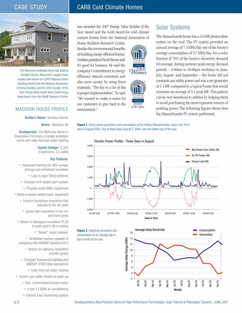
p. 2 Building America Best Practices Series for High-Performance Technologies: Solar Thermal & Photovoltaic Systems - JUNE 2007
CARB Cold Climate HomesCASE STUDY
was awarded the 2007 Energy Value Builder of the Year Award and the Gold Award for cold climate custom homes from the National Association of Home Builders Research Center. Besides the environmental benefits of building energy-efficient homes, Veridian president David Simon said it’s good for business. He said the company’s commitment to energy efficiency attracts customers and also saves money by using fewer materials. “The key to a lot of this is proper implementation,” he said. “We wanted to make it easier for our customers to give back to the environment.”
Solar SystemsThe Massachusetts home has a 2.6-kW photovoltaic system on the roof. The PV system provided an annual average of 7.3 kWh/day out of the house’s average consumption of 9.7 kWh/day, for a solar fraction of 76% of the home’s electricity demand On average, during summer peak energy demand periods – 6:00am to 10:00pm weekdays in June, July, August, and September – the home did not consume any utility power and was a net generator of 1.4 kW, compared to a typical home that would consume an average of 5.1 peak kW. This pattern can be very beneficial to utilities by helping them to avoid purchasing the most expensive sources of peaking power. The following figures shows how the Massachusetts PV system performed.
The Wisconsin prototype home was built by Veridian Homes, Wisconsin’s largest home
builder and winner of a 2005 National Green Building Award from the National Association
of Home Builders, and the 2007 Builder of the Year Energy Value Award and a Gold Energy
Value Award from the NAHB Research Center.
Electric Power Profile - Three Days in August
8/1/04 0:00 8/1/04 12:00 8/2/04 0:00 8/2/04 12:00 8/3/04 0:00 8/3/04 12:00 8/4/04 0:00
Date & Time
Net Power from Utility (W)
AC PV Power (W)
House Load (W)
-2,000
-1,000
0
1,000
2,000
3,000
4,000
0
Jan ‘
05
Feb ‘
05
Mar
‘05
Apr ‘
05
May
‘05
Jun ‘
05
Jul ‘0
5
Aug ‘
05
Sep ‘
05
Oct ‘0
5
Nov ‘
05
Dec ‘
05
2
4
6
8
10
12
14
16Average Daily Electricity
Aver
age
Daily
Ene
rgy
(kW
h)
Month
ConsumptionGeneration
MADISON HOUSE PROFILE
Builder’s Name: Veridian Homes
Where: Madison, WI
Development: The Welcome Home in Grandview Commons, a single prototype
home with solar thermal water heating
Square footage: 2,324 4 bedrooms, 2.5 baths
Key Features:
• Advanced framing for 34% lumber savings and enhanced insulation
• Low-e argon filled windows
• Compact and sealed duct system
• Properly sized HVAC equipment
• Direct or power-vented mech. equipment
• Exterior foundation insulation that extends to the sill plate
• Spray foam insulation in the rim and band joists
• Blown-in fiberglass insulation: R-23 in walls and R-50 in ceiling
• “Smart” vapor retarder
• Ventilation system capable of complying with ASHRAE Standard 62.2
• Return air pathway ventilation transfer grilles
• Compact fluorescent lighting and ENERGY STAR rated appliances
• Solar thermal water heating
• Instant. gas water heater as back-up
• Elec. commutated furnace motor
• 2-ton 13 SEER air conditioning
• Electric load monitoring system
Figure 2. Electricity generation and consumption on an average day in each month of the year.
Figure 1. Hourly power generation and consumption at the Hadley, Massachusetts, house over three days in August 2004. One of these days, August 2, 2004, was the hottest day of the year.
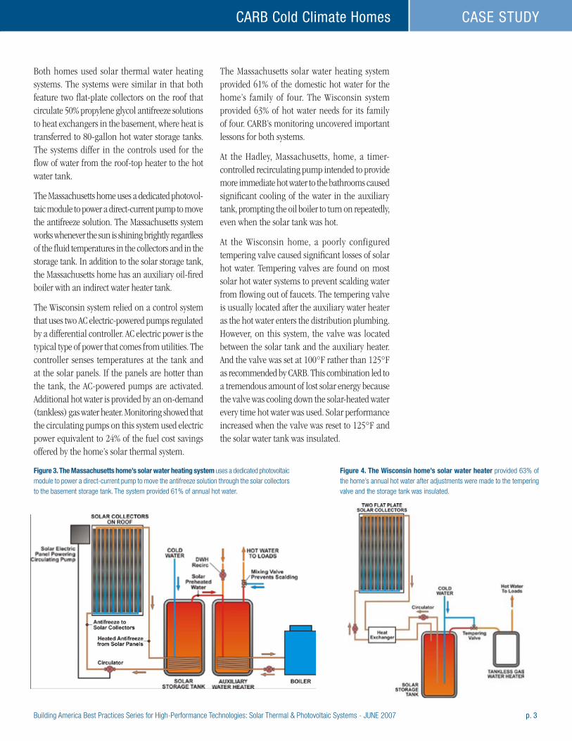
Building America Best Practices Series for High-Performance Technologies: Solar Thermal & Photovoltaic Systems - JUNE 2007 p. 3
CARB Cold Climate Homes CASE STUDY
Both homes used solar thermal water heating systems. The systems were similar in that both feature two flat-plate collectors on the roof that circulate 50% propylene glycol antifreeze solutions to heat exchangers in the basement, where heat is transferred to 80-gallon hot water storage tanks. The systems differ in the controls used for the flow of water from the roof-top heater to the hot water tank.
The Massachusetts home uses a dedicated photovol-taic module to power a direct-current pump to move the antifreeze solution. The Massachusetts system works whenever the sun is shining brightly regardless of the fluid temperatures in the collectors and in the storage tank. In addition to the solar storage tank, the Massachusetts home has an auxiliary oil-fired boiler with an indirect water heater tank.
The Wisconsin system relied on a control system that uses two AC electric-powered pumps regulated by a differential controller. AC electric power is the typical type of power that comes from utilities. The controller senses temperatures at the tank and at the solar panels. If the panels are hotter than the tank, the AC-powered pumps are activated. Additional hot water is provided by an on-demand (tankless) gas water heater. Monitoring showed that the circulating pumps on this system used electric power equivalent to 24% of the fuel cost savings offered by the home’s solar thermal system.
The Massachusetts solar water heating system provided 61% of the domestic hot water for the home’s family of four. The Wisconsin system provided 63% of hot water needs for its family of four. CARB’s monitoring uncovered important lessons for both systems.
At the Hadley, Massachusetts, home, a timer-controlled recirculating pump intended to provide more immediate hot water to the bathrooms caused significant cooling of the water in the auxiliary tank, prompting the oil boiler to turn on repeatedly, even when the solar tank was hot.
At the Wisconsin home, a poorly configured tempering valve caused significant losses of solar hot water. Tempering valves are found on most solar hot water systems to prevent scalding water from flowing out of faucets. The tempering valve is usually located after the auxiliary water heater as the hot water enters the distribution plumbing. However, on this system, the valve was located between the solar tank and the auxiliary heater. And the valve was set at 100°F rather than 125°F as recommended by CARB. This combination led to a tremendous amount of lost solar energy because the valve was cooling down the solar-heated water every time hot water was used. Solar performance increased when the valve was reset to 125°F and the solar water tank was insulated.
Figure 3. The Massachusetts home’s solar water heating system uses a dedicated photovoltaic module to power a direct-current pump to move the antifreeze solution through the solar collectors to the basement storage tank. The system provided 61% of annual hot water.
Figure 4. The Wisconsin home’s solar water heater provided 63% of the home’s annual hot water after adjustments were made to the tempering valve and the storage tank was insulated.
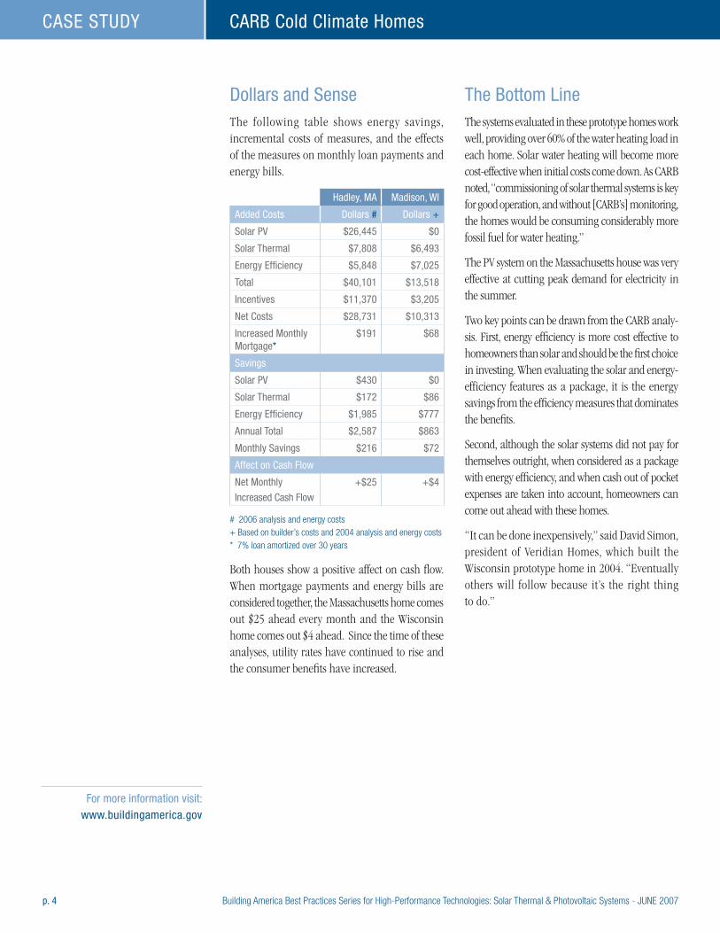
p. 4 Building America Best Practices Series for High-Performance Technologies: Solar Thermal & Photovoltaic Systems - JUNE 2007
CARB Cold Climate HomesCASE STUDY
Dollars and SenseThe following table shows energy savings, incremental costs of measures, and the effects of the measures on monthly loan payments and energy bills.
Hadley, MA Madison, WI
Added Costs Dollars # Dollars +
Solar PV $26,445 $0
Solar Thermal $7,808 $6,493
Energy Efficiency $5,848 $7,025
Total $40,101 $13,518
Incentives $11,370 $3,205
Net Costs $28,731 $10,313
Increased Monthly Mortgage*
$191 $68
Savings
Solar PV $430 $0
Solar Thermal $172 $86
Energy Efficiency $1,985 $777
Annual Total $2,587 $863
Monthly Savings $216 $72
Affect on Cash Flow
Net Monthly
Increased Cash Flow
+$25 +$4
# 2006 analysis and energy costs+ Based on builder’s costs and 2004 analysis and energy costs* 7% loan amortized over 30 years
Both houses show a positive affect on cash flow. When mortgage payments and energy bills are considered together, the Massachusetts home comes out $25 ahead every month and the Wisconsin home comes out $4 ahead. Since the time of these analyses, utility rates have continued to rise and the consumer benefits have increased.
The Bottom LineThe systems evaluated in these prototype homes work well, providing over 60% of the water heating load in each home. Solar water heating will become more cost-effective when initial costs come down. As CARB noted, “commissioning of solar thermal systems is key for good operation, and without [CARB’s] monitoring, the homes would be consuming considerably more fossil fuel for water heating.”
The PV system on the Massachusetts house was very effective at cutting peak demand for electricity in the summer.
Two key points can be drawn from the CARB analy-sis. First, energy efficiency is more cost effective to homeowners than solar and should be the first choice in investing. When evaluating the solar and energy-efficiency features as a package, it is the energy savings from the efficiency measures that dominates the benefits.
Second, although the solar systems did not pay for themselves outright, when considered as a package with energy efficiency, and when cash out of pocket expenses are taken into account, homeowners can come out ahead with these homes.
“It can be done inexpensively,” said David Simon, president of Veridian Homes, which built the Wisconsin prototype home in 2004. “Eventually others will follow because it’s the right thing to do.”
For more information visit: www.buildingamerica.gov
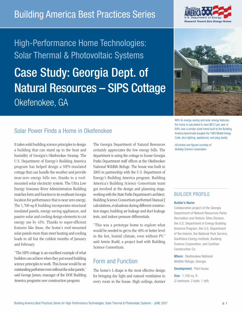
Building America Best Practices Series for High-Performance Technologies: Solar Thermal & Photovoltaic Systems - JUNE 2007 p. 1
High-Performance Home Technologies: Solar Thermal & Photovoltaic Systems
Case Study: Georgia Dept. of Natural Resources – SIPS Cottage Okefenokee, GA
Building America Best Practices Series
It takes solid building science principles to design a building that can stand up to the heat and humidity of Georgia’s Okefenokee Swamp. The U.S. Department of Energy’s Building America program has helped design a SIPS-insulated cottage that can handle the weather and provide near-zero energy bills too, thanks to a roof-mounted solar electricity system. The Ultra Low Energy Suwanee River Administration Building matches form and function to its southeast Georgia location for performance that is near zero energy. The 1,700-sq-ft building incorporates structural insulated panels, energy-saving appliances, and passive solar and cooling design elements to cut energy use by 43%. Thanks to super-efficient features like these, the home’s roof-mounted solar panels more than meet heating and cooling loads in all but the coldest months of January and February.
“The SIPS cottage is an excellent example of what builders can achieve when they put sound building science principles to work. This house would be an outstanding performer even without the solar panels,” said George James, manager of the DOE Building America programs new construction program.
The Georgia Department of Natural Resources certainly appreciates the low energy bills. The department is using the cottage to house Georgia Parks Department staff offices at the Okefenokee National Wildlife Refuge. The house was built in 2003 in partnership with the U.S. Department of Energy’s Building America program. Building America’s Building Science Consortium team got involved at the design and planning stage, working with the State Parks Department’s architect. Building Science Consortium performed Manual J calculations, evaluations during different construc-tion stages, building air leakage and duct leakage tests, and indoor pressure differentials.
“This was a prototype home to explore what would be needed to get to the 40% or better level in the hot, humid climate, even without PV,” said Armin Rudd, a project lead with Building Science Consortium.
Form and FunctionThe home’s L-shape is the most effective design for bringing day light and natural ventilation to every room in the house. High ceilings, dormer
BUILDER PROFILE
Builder’s Name:
Collaborative project of the Georgia
Department of Natural Resources Parks
Recreation and Historic Sites Division,
the U.S. Department of Energy Building
America Program, the U.S. Department
of the Interior, the National Park Service,
Southface Energy Institute, Building
Science Corporation, and Canthan
Construction Co.
Where: Okefenokee National
Wildlife Refuge, Georgia
Development: Pilot house
Size: 1,700 sq. ft.
(2 bedroom, 2 bath, 1 loft)
With its energy-saving and solar energy features, the home is calculated to save $812 per year or 69% over a similar sized home built to the Building America benchmark (roughly the 1993 Model Energy Code, plus lighting, appliances, and plug loads).
All photos and figures courtesy of Building Science Corporation.
Solar Power Finds a Home in Okefenokee
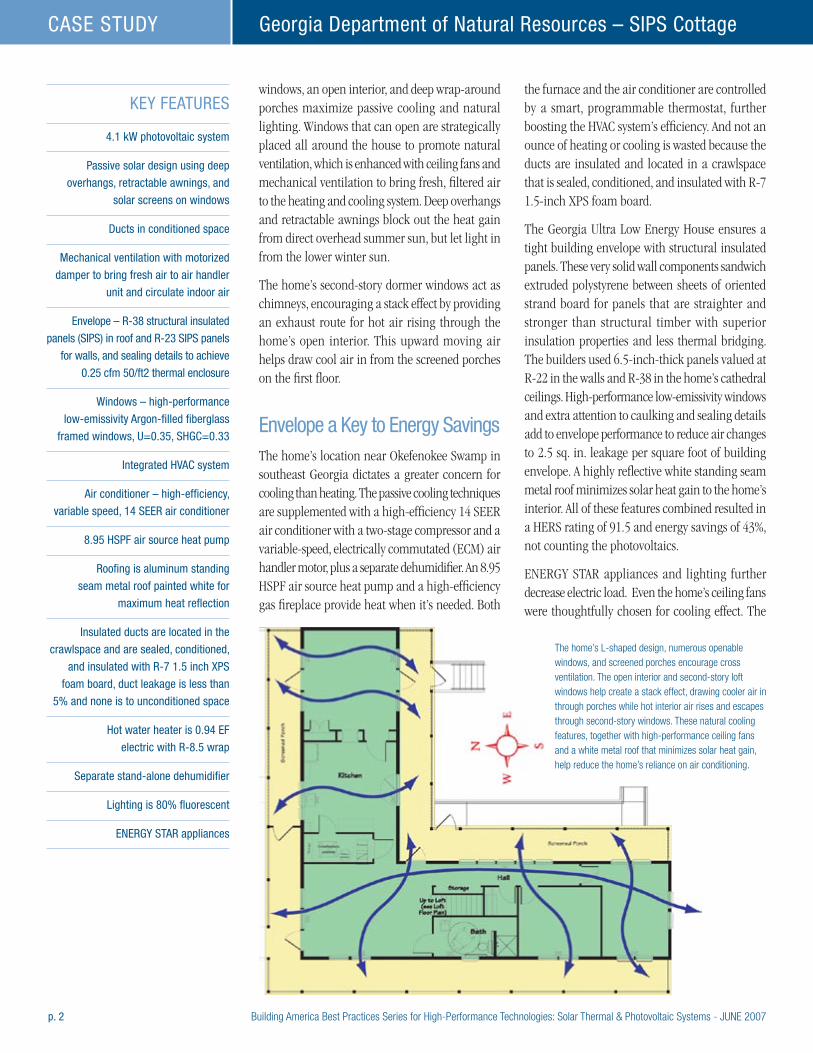
p. 2 Building America Best Practices Series for High-Performance Technologies: Solar Thermal & Photovoltaic Systems - JUNE 2007
Georgia Department of Natural Resources – SIPS CottageCASE STUDY
windows, an open interior, and deep wrap-around porches maximize passive cooling and natural lighting. Windows that can open are strategically placed all around the house to promote natural ventilation, which is enhanced with ceiling fans and mechanical ventilation to bring fresh, filtered air to the heating and cooling system. Deep overhangs and retractable awnings block out the heat gain from direct overhead summer sun, but let light in from the lower winter sun.
The home’s second-story dormer windows act as chimneys, encouraging a stack effect by providing an exhaust route for hot air rising through the home’s open interior. This upward moving air helps draw cool air in from the screened porches on the first floor.
Envelope a Key to Energy SavingsThe home’s location near Okefenokee Swamp in southeast Georgia dictates a greater concern for cooling than heating. The passive cooling techniques are supplemented with a high-efficiency 14 SEER air conditioner with a two-stage compressor and a variable-speed, electrically commutated (ECM) air handler motor, plus a separate dehumidifier. An 8.95 HSPF air source heat pump and a high-efficiency gas fireplace provide heat when it’s needed. Both
the furnace and the air conditioner are controlled by a smart, programmable thermostat, further boosting the HVAC system’s efficiency. And not an ounce of heating or cooling is wasted because the ducts are insulated and located in a crawlspace that is sealed, conditioned, and insulated with R-7 1.5-inch XPS foam board.
The Georgia Ultra Low Energy House ensures a tight building envelope with structural insulated panels. These very solid wall components sandwich extruded polystyrene between sheets of oriented strand board for panels that are straighter and stronger than structural timber with superior insulation properties and less thermal bridging. The builders used 6.5-inch-thick panels valued at R-22 in the walls and R-38 in the home’s cathedral ceilings. High-performance low-emissivity windows and extra attention to caulking and sealing details add to envelope performance to reduce air changes to 2.5 sq. in. leakage per square foot of building envelope. A highly reflective white standing seam metal roof minimizes solar heat gain to the home’s interior. All of these features combined resulted in a HERS rating of 91.5 and energy savings of 43%, not counting the photovoltaics.
ENERGY STAR appliances and lighting further decrease electric load. Even the home’s ceiling fans were thoughtfully chosen for cooling effect. The
KEY FEATURES
4.1 kW photovoltaic system
Passive solar design using deep
overhangs, retractable awnings, and
solar screens on windows
Ducts in conditioned space
Mechanical ventilation with motorized
damper to bring fresh air to air handler
unit and circulate indoor air
Envelope – R-38 structural insulated
panels (SIPS) in roof and R-23 SIPS panels
for walls, and sealing details to achieve
0.25 cfm 50/ft2 thermal enclosure
Windows – high-performance
low-emissivity Argon-filled fiberglass
framed windows, U=0.35, SHGC=0.33
Integrated HVAC system
Air conditioner – high-efficiency,
variable speed, 14 SEER air conditioner
8.95 HSPF air source heat pump
Roofing is aluminum standing
seam metal roof painted white for
maximum heat reflection
Insulated ducts are located in the
crawlspace and are sealed, conditioned,
and insulated with R-7 1.5 inch xPS
foam board, duct leakage is less than
5% and none is to unconditioned space
Hot water heater is 0.94 EF
electric with R-8.5 wrap
Separate stand-alone dehumidifier
Lighting is 80% fluorescent
ENERGY STAR appliances
The home’s L-shaped design, numerous openable windows, and screened porches encourage cross ventilation. The open interior and second-story loft windows help create a stack effect, drawing cooler air in through porches while hot interior air rises and escapes through second-story windows. These natural cooling features, together with high-performance ceiling fans and a white metal roof that minimizes solar heat gain, help reduce the home’s reliance on air conditioning.
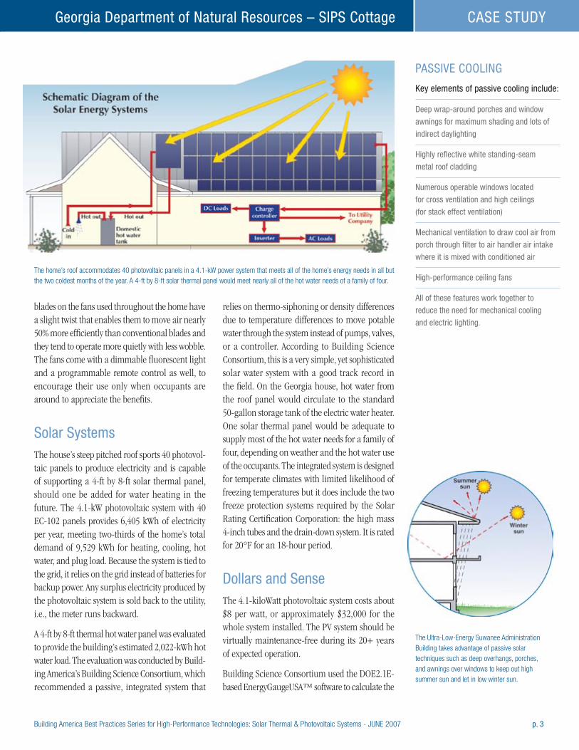
Building America Best Practices Series for High-Performance Technologies: Solar Thermal & Photovoltaic Systems - JUNE 2007 p. 3
Georgia Department of Natural Resources – SIPS Cottage CASE STUDY
blades on the fans used throughout the home have a slight twist that enables them to move air nearly 50% more efficiently than conventional blades and they tend to operate more quietly with less wobble. The fans come with a dimmable fluorescent light and a programmable remote control as well, to encourage their use only when occupants are around to appreciate the benefits.
Solar SystemsThe house’s steep pitched roof sports 40 photovol-taic panels to produce electricity and is capable of supporting a 4-ft by 8-ft solar thermal panel, should one be added for water heating in the future. The 4.1-kW photovoltaic system with 40 EC-102 panels provides 6,405 kWh of electricity per year, meeting two-thirds of the home’s total demand of 9,529 kWh for heating, cooling, hot water, and plug load. Because the system is tied to the grid, it relies on the grid instead of batteries for backup power. Any surplus electricity produced by the photovoltaic system is sold back to the utility, i.e., the meter runs backward.
A 4-ft by 8-ft thermal hot water panel was evaluated to provide the building’s estimated 2,022-kWh hot water load. The evaluation was conducted by Build-ing America’s Building Science Consortium, which recommended a passive, integrated system that
relies on thermo-siphoning or density differences due to temperature differences to move potable water through the system instead of pumps, valves, or a controller. According to Building Science Consortium, this is a very simple, yet sophisticated solar water system with a good track record in the field. On the Georgia house, hot water from the roof panel would circulate to the standard 50-gallon storage tank of the electric water heater. One solar thermal panel would be adequate to supply most of the hot water needs for a family of four, depending on weather and the hot water use of the occupants. The integrated system is designed for temperate climates with limited likelihood of freezing temperatures but it does include the two freeze protection systems required by the Solar Rating Certification Corporation: the high mass 4-inch tubes and the drain-down system. It is rated for 20°F for an 18-hour period.
Dollars and SenseThe 4.1-kiloWatt photovoltaic system costs about $8 per watt, or approximately $32,000 for the whole system installed. The PV system should be virtually maintenance-free during its 20+ years of expected operation.
Building Science Consortium used the DOE2.1E-based EnergyGaugeUSA™ software to calculate the
The Ultra-Low-Energy Suwanee Administration Building takes advantage of passive solar techniques such as deep overhangs, porches, and awnings over windows to keep out high summer sun and let in low winter sun.
PASSIVE COOLING
Key elements of passive cooling include:
Deep wrap-around porches and window
awnings for maximum shading and lots of
indirect daylighting
Highly reflective white standing-seam
metal roof cladding
Numerous operable windows located
for cross ventilation and high ceilings
(for stack effect ventilation)
Mechanical ventilation to draw cool air from
porch through filter to air handler air intake
where it is mixed with conditioned air
High-performance ceiling fans
All of these features work together to
reduce the need for mechanical cooling
and electric lighting.
The home’s roof accommodates 40 photovoltaic panels in a 4.1-kW power system that meets all of the home’s energy needs in all but the two coldest months of the year. A 4-ft by 8-ft solar thermal panel would meet nearly all of the hot water needs of a family of four.
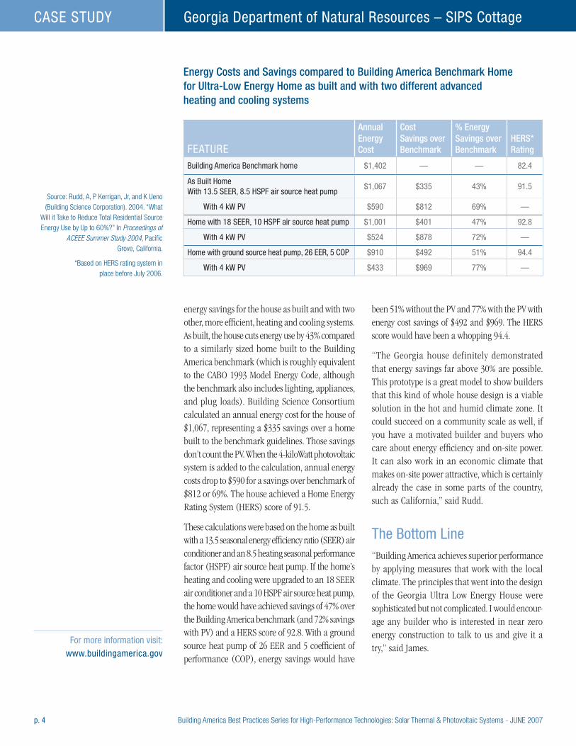
p. 4 Building America Best Practices Series for High-Performance Technologies: Solar Thermal & Photovoltaic Systems - JUNE 2007
Georgia Department of Natural Resources – SIPS CottageCASE STUDY
energy savings for the house as built and with two other, more efficient, heating and cooling systems. As built, the house cuts energy use by 43% compared to a similarly sized home built to the Building America benchmark (which is roughly equivalent to the CABO 1993 Model Energy Code, although the benchmark also includes lighting, appliances, and plug loads). Building Science Consortium calculated an annual energy cost for the house of $1,067, representing a $335 savings over a home built to the benchmark guidelines. Those savings don’t count the PV. When the 4-kiloWatt photovoltaic system is added to the calculation, annual energy costs drop to $590 for a savings over benchmark of $812 or 69%. The house achieved a Home Energy Rating System (HERS) score of 91.5.
These calculations were based on the home as built with a 13.5 seasonal energy efficiency ratio (SEER) air conditioner and an 8.5 heating seasonal performance factor (HSPF) air source heat pump. If the home’s heating and cooling were upgraded to an 18 SEER air conditioner and a 10 HSPF air source heat pump, the home would have achieved savings of 47% over the Building America benchmark (and 72% savings with PV) and a HERS score of 92.8. With a ground source heat pump of 26 EER and 5 coefficient of performance (COP), energy savings would have
been 51% without the PV and 77% with the PV with energy cost savings of $492 and $969. The HERS score would have been a whopping 94.4.
“The Georgia house definitely demonstrated that energy savings far above 30% are possible. This prototype is a great model to show builders that this kind of whole house design is a viable solution in the hot and humid climate zone. It could succeed on a community scale as well, if you have a motivated builder and buyers who care about energy efficiency and on-site power. It can also work in an economic climate that makes on-site power attractive, which is certainly already the case in some parts of the country, such as California,” said Rudd.
The Bottom Line“Building America achieves superior performance by applying measures that work with the local climate. The principles that went into the design of the Georgia Ultra Low Energy House were sophisticated but not complicated. I would encour-age any builder who is interested in near zero energy construction to talk to us and give it a try,” said James.
Energy Costs and Savings compared to Building America Benchmark Home for Ultra-Low Energy Home as built and with two different advanced heating and cooling systems
FEATURE
Annual Energy Cost
Cost Savings over Benchmark
% Energy Savings over Benchmark
HERS* Rating
Building America Benchmark home $1,402 — — 82.4
As Built Home With 13.5 SEER, 8.5 HSPF air source heat pump
$1,067 $335 43% 91.5
With 4 kW PV $590 $812 69% —
Home with 18 SEER, 10 HSPF air source heat pump $1,001 $401 47% 92.8
With 4 kW PV $524 $878 72% —
Home with ground source heat pump, 26 EER, 5 COP $910 $492 51% 94.4
With 4 kW PV $433 $969 77% —
For more information visit: www.buildingamerica.gov
Source: Rudd, A, P Kerrigan, Jr, and K Ueno (Building Science Corporation). 2004. “What
Will it Take to Reduce Total Residential Source Energy Use by Up to 60%?” In Proceedings of
ACEEE Summer Study 2004, Pacific Grove, California.
*Based on HERS rating system in place before July 2006.

Building America Best Practices Series for High-Performance Technologies: Solar Thermal & Photovoltaic Systems - JUNE 2007 p. 1
High-Performance Home Technologies: Solar Thermal & Photovoltaic Systems
Case Study: Grupe – Carsten Crossings Rocklin, CA
Building America Best Practices Series
In the volatile California housing market, zero energy construction has helped Stockton area home builder Grupe to standout from the competition. “Zero energy has definitely helped us close deals,” said Mark Fischer, a senior vice president at Grupe.
Sacramento’s new home market took a nosedive with sales dropping by up to 45% between 2005 and March 2006, just when the first 10 of the 144 homes at Grupe’s Carsten Crossings project were completed. “We sold 23 of our first 30 homes in the first three months, even though the market in Sacramento is very slow right now; it is the slowest housing market in the country. Our project is doing better than most of our competitors,” said Fischer.
The cost of doing business, and a major part of profitability, is driven by the time required to sell out a community. Reducing this time by selling houses faster has a significant affect on the builder’s costs. Mark Fischer reported at a builders conference that Grupe achieved a sales rate of 4.6 home sales per month versus 1.9 for their competitors, a rate 2.5 times faster than their competition. Grupe has calculated that if only about 19% of their increased sales rate was due to energy efficiency, solar PV, and green features, the increased cost of $2.6 million in marketing and increased materials costs paid for
them self. If the trend continues, Grupe will save a total of $14 million.
In this first solar development for Grupe, solar was made a standard feature on all 144 houses. “We certainly like the fact that it makes us unique, and we feel good about offering it because we think solar is the right thing to do,” said Fischer. Photovoltaics are only part of the equation. Grupe anticipates that Carsten Crossings homeowners will see annual utility savings of up to 70% more than homes built to the California energy code thanks to both the photovoltaics, and an impressive mix of energy-efficient features that are being offered as standard features by Grupe.
“Making solar a standard feature instead of an optional upgrade is the way to do it,” said David Springer of Davis Energy Group, which is a partner in the U.S. Department of Energy’s Building America program. Springer worked with Grupe on the Carsten Springs Project. “That’s been our experience on previous projects. Grupe was able to negotiate a much better deal with their contractors by making it standard across the project,” said Springer.
Other builders have found that when solar is offered as an upgrade, buyers will often choose
BUILDER PROFILE
Builder’s Name: Grupe
Where: Stockton, CA
Founded: 1966, 50,000 homes
built as of September 2006
Employees: 70
Development:
Carsten Crossings at Whitney Ranch
in Rocklin, CA
Size: 144 homes
Square footage: 2,168-2,755 sq.ft.
(3-5 bedroom, 3 baths)
Price: From $478,000 to $528,000
Number of homes per year:
300 to 400 homes
Solar status:
First zero energy development, an
ENERGY STAR builder for 10 years
Zero Energy Sets Sacramento Area Builder Apart
Grupe chose to make photovoltaics a standard feature on every one of the 144 homes it is building at Carsten Crossings in Rocklin, California.
Grupe’s Carsten Crossing Community won the gold award for moderate climate production homes in the 2007 Energy Value Housing Award competition held by the National Association of Home Builders Research Center.
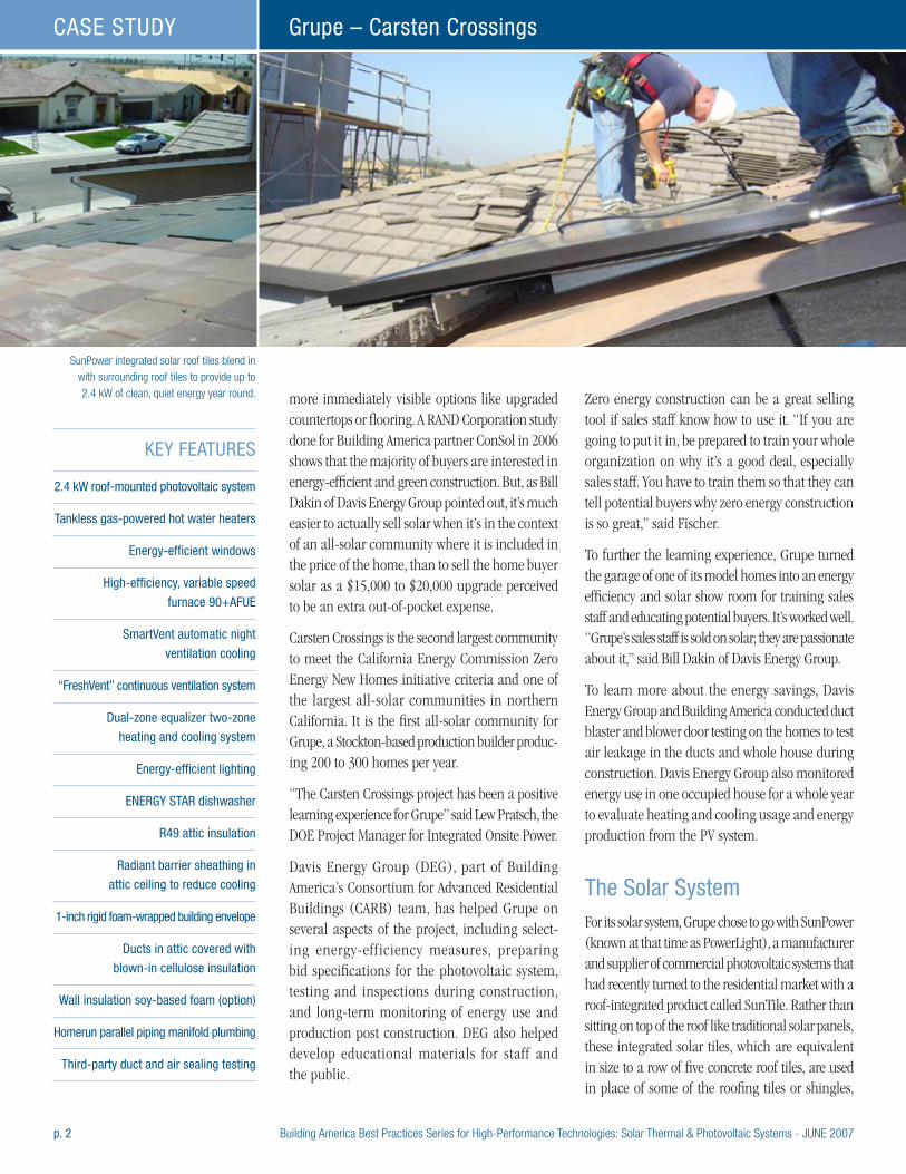
p. 2 Building America Best Practices Series for High-Performance Technologies: Solar Thermal & Photovoltaic Systems - JUNE 2007
Grupe – Carsten CrossingsCASE STUDY
more immediately visible options like upgraded countertops or flooring. A RAND Corporation study done for Building America partner ConSol in 2006 shows that the majority of buyers are interested in energy-efficient and green construction. But, as Bill Dakin of Davis Energy Group pointed out, it’s much easier to actually sell solar when it’s in the context of an all-solar community where it is included in the price of the home, than to sell the home buyer solar as a $15,000 to $20,000 upgrade perceived to be an extra out-of-pocket expense.
Carsten Crossings is the second largest community to meet the California Energy Commission Zero Energy New Homes initiative criteria and one of the largest all-solar communities in northern California. It is the first all-solar community for Grupe, a Stockton-based production builder produc-ing 200 to 300 homes per year.
“The Carsten Crossings project has been a positive learning experience for Grupe” said Lew Pratsch, the DOE Project Manager for Integrated Onsite Power.
Davis Energy Group (DEG), part of Building America’s Consortium for Advanced Residential Buildings (CARB) team, has helped Grupe on several aspects of the project, including select-ing energy-efficiency measures, preparing bid specifications for the photovoltaic system, testing and inspections during construction, and long-term monitoring of energy use and production post construction. DEG also helped develop educational materials for staff and the public.
Zero energy construction can be a great selling tool if sales staff know how to use it. “If you are going to put it in, be prepared to train your whole organization on why it’s a good deal, especially sales staff. You have to train them so that they can tell potential buyers why zero energy construction is so great,” said Fischer.
To further the learning experience, Grupe turned the garage of one of its model homes into an energy efficiency and solar show room for training sales staff and educating potential buyers. It’s worked well. “Grupe’s sales staff is sold on solar; they are passionate about it,” said Bill Dakin of Davis Energy Group.
To learn more about the energy savings, Davis Energy Group and Building America conducted duct blaster and blower door testing on the homes to test air leakage in the ducts and whole house during construction. Davis Energy Group also monitored energy use in one occupied house for a whole year to evaluate heating and cooling usage and energy production from the PV system.
The Solar SystemFor its solar system, Grupe chose to go with SunPower (known at that time as PowerLight), a manufacturer and supplier of commercial photovoltaic systems that had recently turned to the residential market with a roof-integrated product called SunTile. Rather than sitting on top of the roof like traditional solar panels, these integrated solar tiles, which are equivalent in size to a row of five concrete roof tiles, are used in place of some of the roofing tiles or shingles,
KEY FEATURES
2.4 kW roof-mounted photovoltaic system
Tankless gas-powered hot water heaters
Energy-efficient windows
High-efficiency, variable speed
furnace 90+AFUE
SmartVent automatic night
ventilation cooling
“FreshVent” continuous ventilation system
Dual-zone equalizer two-zone
heating and cooling system
Energy-efficient lighting
ENERGY STAR dishwasher
R49 attic insulation
Radiant barrier sheathing in
attic ceiling to reduce cooling
1-inch rigid foam-wrapped building envelope
Ducts in attic covered with
blown-in cellulose insulation
Wall insulation soy-based foam (option)
Homerun parallel piping manifold plumbing
Third-party duct and air sealing testing
SunPower integrated solar roof tiles blend in with surrounding roof tiles to provide up to 2.4 kW of clean, quiet energy year round.
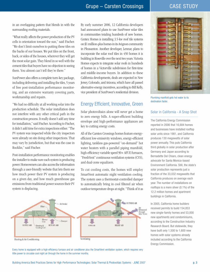
Building America Best Practices Series for High-Performance Technologies: Solar Thermal & Photovoltaic Systems - JUNE 2007 p. 3
Grupe – Carsten Crossings CASE STUDY
in an overlapping pattern that blends in with the surrounding roofing materials.
“What really affects the power production of the PV cells is orientation toward the sun,” said Fischer. “We don’t limit ourselves to putting these tiles on the backs of our houses. We put tiles on the front, back, or sides of the houses, wherever they will get the most solar gain. They blend in so well with the cement tiles that buyers have no objection to seeing them. You almost can’t tell they’re there.”
SunPower also offers a complete turn-key package, including delivering and installing the tiles, 5 years of free post-installation performance monitor-ing, and an extensive warranty covering parts, workmanship and repairs.
“We had no difficulty at all working solar into the production schedule. The solar installation does not interfere with any other critical path in the construction process. It really doesn’t add any time for installation,” said Fischer. According to Fischer, it didn’t add time for extra inspections either. “The PV system was inspected while the city inspectors were already on site doing other inspections. That may vary by jurisdiction, but that was the case in Rocklin,” said Fischer.
Post-installation performance monitoring enables the installer to make sure each system is producing power. Homeowners can also access the information through a user-friendly website that lets them see how much power their PV system is producing on a given day, and how much greenhouse gas emissions from traditional power sources their PV system is displacing.
By early summer 2006, 12 California developers had announced plans to use SunPower solar tiles in communities totaling hundreds of new homes. Centex Homes is installing 3.5-kw roof tile systems on $1 million-plus homes in its Avignon community in Pleasanton. Another developer, Lennar, plans to incorporate the solar roof tiles in 450 homes it is building in Roseville over the next two years. Victoria Homes expects to integrate solar roofs in hundreds of homes in a Victorville subdivision for first-time and middle-income buyers. In addition to these California developments, deals are expected in New Jersey, Colorado, and Arizona, which have all passed alternative-energy incentives, according to Bill Kelly, vice president of SunPower’s residential division.
Energy Efficient, Innovative, GreenSolar photovoltaics alone will never get a home to zero energy bills. A super-efficient building envelope and high-performance appliances are key to cutting energy costs.
All of the Carsten Crossings homes feature energy-efficient low-emissivity windows, energy-efficient lighting, tankless gas-powered “on-demand” hot water heaters with a parallel piping manifold, high-efficiency variable speed 90+ AFUE furnaces, “FreshVent” continuous ventilation systems (CVS), and dual-zone equalizers.
To cut cooling costs, the homes will employ SmartVent automatic night ventilation cooling. The system uses a thermostat-controlled damper to automatically bring in cool filtered air when outdoor temperature drops at night. “Think of it as
Plumbing manifold gets hot water to its destination faster.
Solar in California - A Snap Shot
The California Energy Commission
reported in 2006 that 16,684 homes
and businesses have installed rooftop
solar units since 1981, and California
produces 130 megawatts of solar
power annually. This puts California
third globally in solar production after
Germany and Japan according to
Bernadette Del Chiaro, clean energy
advocate for Santa Monica-based
Environment California. Still, the state’s
solar production represents just a
fraction of the 33,032 megawatts that
California produces on average each
year. The number of installations on
rooftops is a mere sliver (0.1%) of the
12.2 million homes and apartment
buildings in California.
In 2005, California home builders
received permits to build 154,853
new single-family homes and 53,000
new apartments and condominiums,
according to the Construction Industry
Research Board. But statewide, they
have built only 1,500 to 1,600 new
homes with solar systems already
included according to the California
Energy Commission.
Every home is equipped with a high-efficiency furnace and air conditioner plus the SmartVent ventilation system, which requires very little power to circulate cool night air through the home in the summer months.
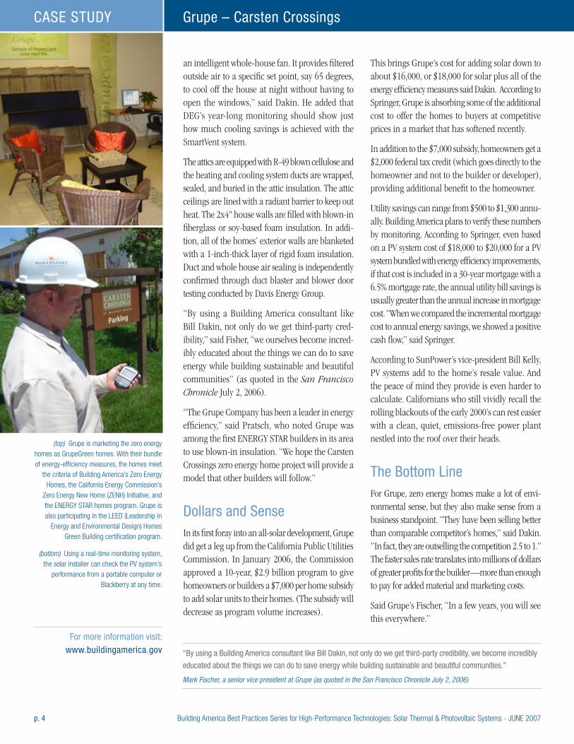
p. 4 Building America Best Practices Series for High-Performance Technologies: Solar Thermal & Photovoltaic Systems - JUNE 2007
Grupe – Carsten CrossingsCASE STUDY
an intelligent whole-house fan. It provides filtered outside air to a specific set point, say 65 degrees, to cool off the house at night without having to open the windows,” said Dakin. He added that DEG’s year-long monitoring should show just how much cooling savings is achieved with the SmartVent system.
The attics are equipped with R-49 blown cellulose and the heating and cooling system ducts are wrapped, sealed, and buried in the attic insulation. The attic ceilings are lined with a radiant barrier to keep out heat. The 2x4" house walls are filled with blown-in fiberglass or soy-based foam insulation. In addi-tion, all of the homes’ exterior walls are blanketed with a 1-inch-thick layer of rigid foam insulation. Duct and whole house air sealing is independently confirmed through duct blaster and blower door testing conducted by Davis Energy Group.
“By using a Building America consultant like Bill Dakin, not only do we get third-party cred-ibility,” said Fisher, “we ourselves become incred-ibly educated about the things we can do to save energy while building sustainable and beautiful communities” (as quoted in the San Francisco Chronicle July 2, 2006).
“The Grupe Company has been a leader in energy efficiency,” said Pratsch, who noted Grupe was among the first ENERGY STAR builders in its area to use blown-in insulation. “We hope the Carsten Crossings zero energy home project will provide a model that other builders will follow.”
Dollars and SenseIn its first foray into an all-solar development, Grupe did get a leg up from the California Public Utilities Commission. In January 2006, the Commission approved a 10-year, $2.9 billion program to give homeowners or builders a $7,000 per home subsidy to add solar units to their homes. (The subsidy will decrease as program volume increases).
This brings Grupe’s cost for adding solar down to about $16,000, or $18,000 for solar plus all of the energy efficiency measures said Dakin. According to Springer, Grupe is absorbing some of the additional cost to offer the homes to buyers at competitive prices in a market that has softened recently.
In addition to the $7,000 subsidy, homeowners get a $2,000 federal tax credit (which goes directly to the homeowner and not to the builder or developer), providing additional benefit to the homeowner.
Utility savings can range from $500 to $1,300 annu-ally. Building America plans to verify these numbers by monitoring. According to Springer, even based on a PV system cost of $18,000 to $20,000 for a PV system bundled with energy efficiency improvements, if that cost is included in a 30-year mortgage with a 6.5% mortgage rate, the annual utility bill savings is usually greater than the annual increase in mortgage cost. “When we compared the incremental mortgage cost to annual energy savings, we showed a positive cash flow,” said Springer.
According to SunPower’s vice-president Bill Kelly, PV systems add to the home’s resale value. And the peace of mind they provide is even harder to calculate. Californians who still vividly recall the rolling blackouts of the early 2000’s can rest easier with a clean, quiet, emissions-free power plant nestled into the roof over their heads.
The Bottom LineFor Grupe, zero energy homes make a lot of envi-ronmental sense, but they also make sense from a business standpoint. “They have been selling better than comparable competitor’s homes,” said Dakin. “In fact, they are outselling the competition 2.5 to 1.” The faster sales rate translates into millions of dollars of greater profits for the builder—more than enough to pay for added material and marketing costs.
Said Grupe’s Fischer, “In a few years, you will see this everywhere.”
(top) Grupe is marketing the zero energy homes as GrupeGreen homes. With their bundle of energy-efficiency measures, the homes meet
the criteria of Building America’s Zero Energy Homes, the California Energy Commission’s
Zero Energy New Home (ZENH) Initiative, and the ENERGY STAR homes program. Grupe is also participating in the LEED (Leadership in
Energy and Environmental Design) Homes Green Building certification program.
(bottom) Using a real-time monitoring system, the solar installer can check the PV system’s
performance from a portable computer or Blackberry at any time.
“By using a Building America consultant like Bill Dakin, not only do we get third-party credibility, we become incredibly
educated about the things we can do to save energy while building sustainable and beautiful communities.” Mark Fischer, a senior vice president at Grupe (as quoted in the San Francisco Chronicle July 2, 2006)
For more information visit: www.buildingamerica.gov
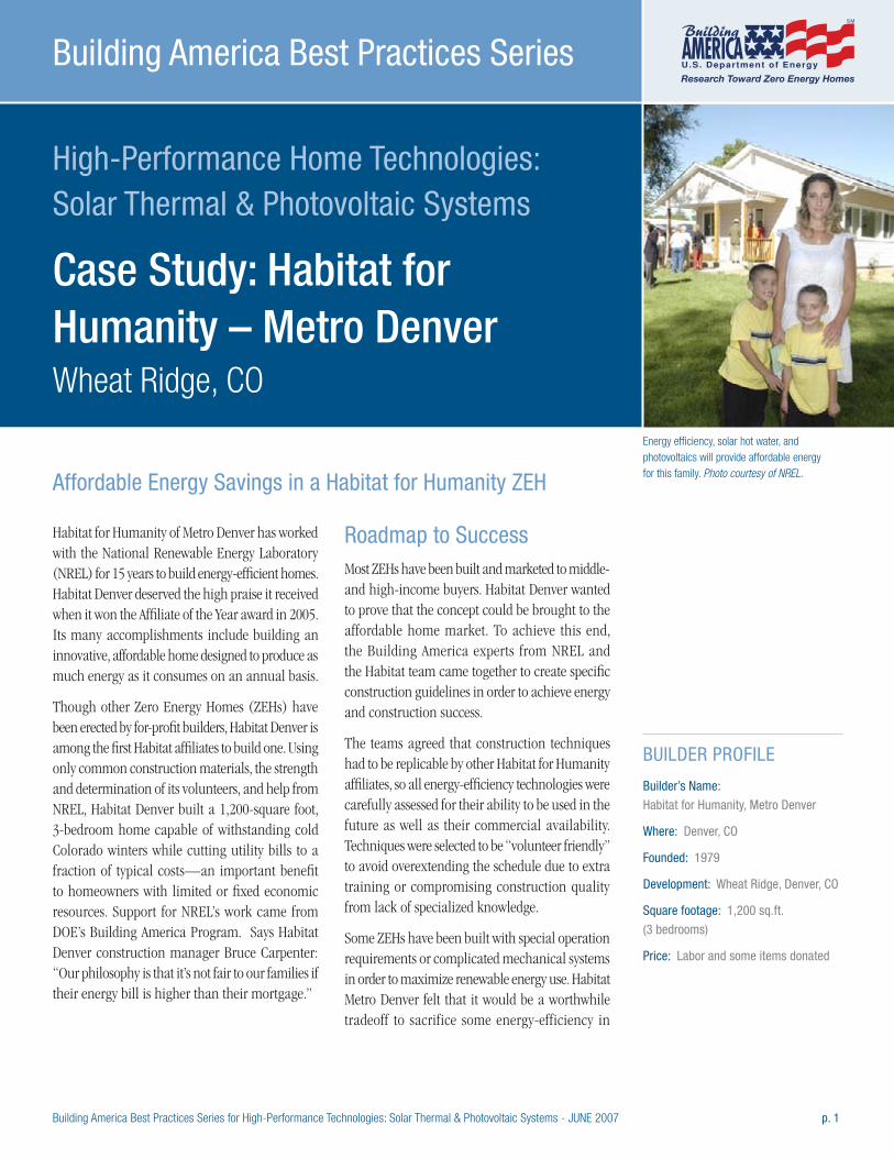
Building America Best Practices Series for High-Performance Technologies: Solar Thermal & Photovoltaic Systems - JUNE 2007 p. 1
High-Performance Home Technologies: Solar Thermal & Photovoltaic Systems
Case Study: Habitat for Humanity – Metro Denver Wheat Ridge, CO
Building America Best Practices Series
Habitat for Humanity of Metro Denver has worked with the National Renewable Energy Laboratory (NREL) for 15 years to build energy-efficient homes. Habitat Denver deserved the high praise it received when it won the Affiliate of the Year award in 2005. Its many accomplishments include building an innovative, affordable home designed to produce as much energy as it consumes on an annual basis.
Though other Zero Energy Homes (ZEHs) have been erected by for-profit builders, Habitat Denver is among the first Habitat affiliates to build one. Using only common construction materials, the strength and determination of its volunteers, and help from NREL, Habitat Denver built a 1,200-square foot, 3-bedroom home capable of withstanding cold Colorado winters while cutting utility bills to a fraction of typical costs—an important benefit to homeowners with limited or fixed economic resources. Support for NREL’s work came from DOE’s Building America Program. Says Habitat Denver construction manager Bruce Carpenter: “Our philosophy is that it’s not fair to our families if their energy bill is higher than their mortgage.”
Roadmap to SuccessMost ZEHs have been built and marketed to middle- and high-income buyers. Habitat Denver wanted to prove that the concept could be brought to the affordable home market. To achieve this end, the Building America experts from NREL and the Habitat team came together to create specific construction guidelines in order to achieve energy and construction success.
The teams agreed that construction techniques had to be replicable by other Habitat for Humanity affiliates, so all energy-efficiency technologies were carefully assessed for their ability to be used in the future as well as their commercial availability. Techniques were selected to be “volunteer friendly” to avoid overextending the schedule due to extra training or compromising construction quality from lack of specialized knowledge.
Some ZEHs have been built with special operation requirements or complicated mechanical systems in order to maximize renewable energy use. Habitat Metro Denver felt that it would be a worthwhile tradeoff to sacrifice some energy-efficiency in
BUILDER PROFILE
Builder’s Name:
Habitat for Humanity, Metro Denver
Where: Denver, CO
Founded: 1979
Development: Wheat Ridge, Denver, CO
Square footage: 1,200 sq.ft.
(3 bedrooms)
Price: Labor and some items donated
Energy efficiency, solar hot water, and photovoltaics will provide affordable energy for this family. Photo courtesy of NREL.Affordable Energy Savings in a Habitat for Humanity ZEH
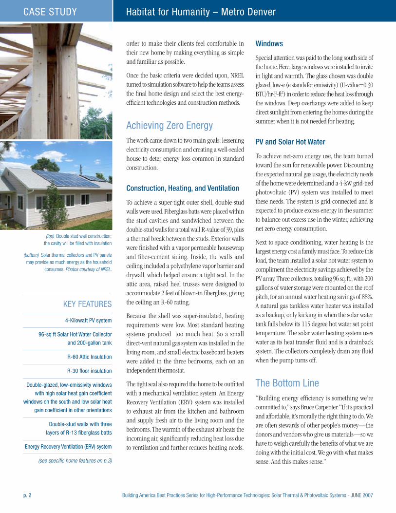
p. 2 Building America Best Practices Series for High-Performance Technologies: Solar Thermal & Photovoltaic Systems - JUNE 2007
Habitat for Humanity – Metro DenverCASE STUDY
order to make their clients feel comfortable in their new home by making everything as simple and familiar as possible.
Once the basic criteria were decided upon, NREL turned to simulation software to help the teams assess the final home design and select the best energy-efficient technologies and construction methods.
Achieving Zero EnergyThe work came down to two main goals: lessening electricity consumption and creating a well-sealed house to deter energy loss common in standard construction.
Construction, Heating, and Ventilation
To achieve a super-tight outer shell, double-stud walls were used. Fiberglass batts were placed within the stud cavities and sandwiched between the double-stud walls for a total wall R-value of 39, plus a thermal break between the studs. Exterior walls were finished with a vapor permeable housewrap and fiber-cement siding. Inside, the walls and ceiling included a polyethylene vapor barrier and drywall, which helped ensure a tight seal. In the attic area, raised heel trusses were designed to accommodate 2 feet of blown-in fiberglass, giving the ceiling an R-60 rating.
Because the shell was super-insulated, heating requirements were low. Most standard heating systems produced too much heat. So a small direct-vent natural gas system was installed in the living room, and small electric baseboard heaters were added in the three bedrooms, each on an independent thermostat.
The tight seal also required the home to be outfitted with a mechanical ventilation system. An Energy Recovery Ventilation (ERV) system was installed to exhaust air from the kitchen and bathroom and supply fresh air to the living room and the bedrooms. The warmth of the exhaust air heats the incoming air, significantly reducing heat loss due to ventilation and further reduces heating needs.
Windows
Special attention was paid to the long south side of the home. Here, large windows were installed to invite in light and warmth. The glass chosen was double glazed, low-e (e stands for emissivity) (U-value=0.30 BTU/hr-F-ft2) in order to reduce the heat loss through the windows. Deep overhangs were added to keep direct sunlight from entering the homes during the summer when it is not needed for heating.
PV and Solar Hot Water
To achieve net-zero energy use, the team turned toward the sun for renewable power. Discounting the expected natural gas usage, the electricity needs of the home were determined and a 4-kW grid-tied photovoltaic (PV) system was installed to meet these needs. The system is grid-connected and is expected to produce excess energy in the summer to balance out excess use in the winter, achieving net zero energy consumption.
Next to space conditioning, water heating is the largest energy cost a family must face. To reduce this load, the team installed a solar hot water system to compliment the electricity savings achieved by the PV array. Three collectors, totaling 96 sq. ft., with 200 gallons of water storage were mounted on the roof pitch, for an annual water heating savings of 88%. A natural gas tankless water heater was installed as a backup, only kicking in when the solar water tank falls below its 115 degree hot water set point temperature. The solar water heating system uses water as its heat transfer fluid and is a drainback system. The collectors completely drain any fluid when the pump turns off.
The Bottom Line“Building energy efficiency is something we’re committed to,” says Bruce Carpenter. “If it’s practical and affordable, it’s morally the right thing to do. We are often stewards of other people’s money—the donors and vendors who give us materials—so we have to weigh carefully the benefits of what we are doing with the initial cost. We go with what makes sense. And this makes sense.”
KEY FEATURES
4-Kilowatt PV system
96-sq ft Solar Hot Water Collector
and 200-gallon tank
R-60 Attic Insulation
R-30 floor insulation
Double-glazed, low-emissivity windows
with high solar heat gain coefficient
windows on the south and low solar heat
gain coefficient in other orientations
Double-stud walls with three
layers of R-13 fiberglass batts
Energy Recovery Ventilation (ERV) system
(see specific home features on p.3)
(top) Double stud wall construction; the cavity will be filled with insulation
(bottom) Solar thermal collectors and PV panels may provide as much energy as the household
consumes. Photos courtesy of NREL.
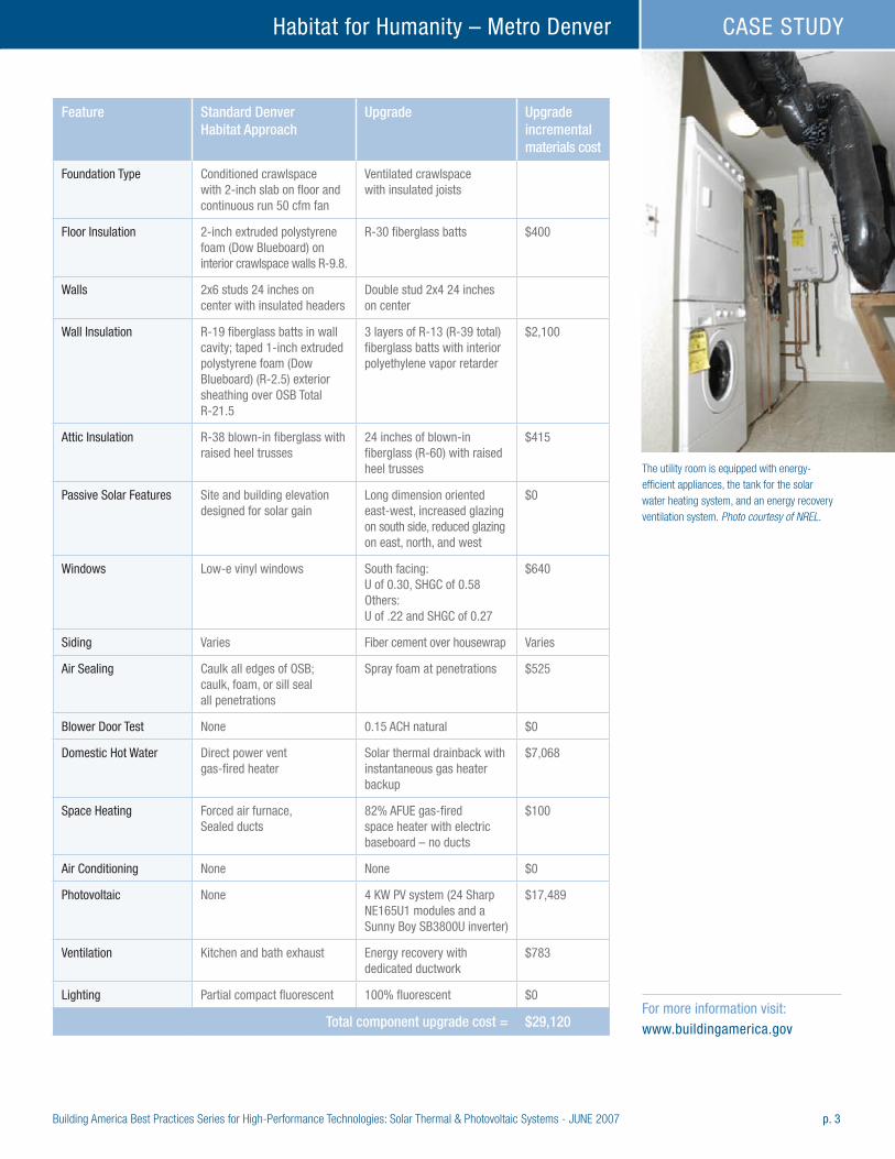
Building America Best Practices Series for High-Performance Technologies: Solar Thermal & Photovoltaic Systems - JUNE 2007 p. 3
Habitat for Humanity – Metro Denver CASE STUDY
Feature Standard Denver Habitat Approach
Upgrade Upgrade incremental materials cost
Foundation Type Conditioned crawlspace with 2-inch slab on floor and continuous run 50 cfm fan
Ventilated crawlspace with insulated joists
Floor Insulation 2-inch extruded polystyrene foam (Dow Blueboard) on interior crawlspace walls R-9.8.
R-30 fiberglass batts $400
Walls 2x6 studs 24 inches on center with insulated headers
Double stud 2x4 24 inches on center
Wall Insulation R-19 fiberglass batts in wall cavity; taped 1-inch extruded polystyrene foam (Dow Blueboard) (R-2.5) exterior sheathing over OSB Total R-21.5
3 layers of R-13 (R-39 total) fiberglass batts with interior polyethylene vapor retarder
$2,100
Attic Insulation R-38 blown-in fiberglass with raised heel trusses
24 inches of blown-in fiberglass (R-60) with raised heel trusses
$415
Passive Solar Features Site and building elevation designed for solar gain
Long dimension oriented east-west, increased glazing on south side, reduced glazing on east, north, and west
$0
Windows Low-e vinyl windows South facing: U of 0.30, SHGC of 0.58 Others: U of .22 and SHGC of 0.27
$640
Siding Varies Fiber cement over housewrap Varies
Air Sealing Caulk all edges of OSB; caulk, foam, or sill seal all penetrations
Spray foam at penetrations $525
Blower Door Test None 0.15 ACH natural $0
Domestic Hot Water Direct power vent gas-fired heater
Solar thermal drainback with instantaneous gas heater backup
$7,068
Space Heating Forced air furnace, Sealed ducts
82% AFUE gas-fired space heater with electric baseboard – no ducts
$100
Air Conditioning None None $0
Photovoltaic None 4 KW PV system (24 Sharp NE165U1 modules and a Sunny Boy SB3800U inverter)
$17,489
Ventilation Kitchen and bath exhaust Energy recovery with dedicated ductwork
$783
Lighting Partial compact fluorescent 100% fluorescent $0
Total component upgrade cost = $29,120
The utility room is equipped with energy-efficient appliances, the tank for the solar water heating system, and an energy recovery ventilation system. Photo courtesy of NREL.
For more information visit: www.buildingamerica.gov
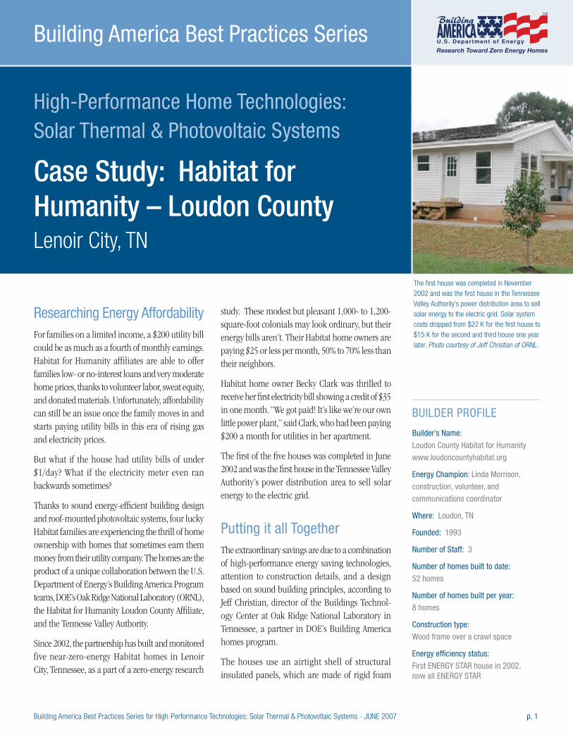
Building America Best Practices Series for High-Performance Technologies: Solar Thermal & Photovoltaic Systems - JUNE 2007 p. 1
High-Performance Home Technologies: Solar Thermal & Photovoltaic Systems
Case Study: Habitat for Humanity – Loudon County Lenoir City, TN
Building America Best Practices Series
Researching Energy Affordability For families on a limited income, a $200 utility bill could be as much as a fourth of monthly earnings. Habitat for Humanity affiliates are able to offer families low- or no-interest loans and very moderate home prices, thanks to volunteer labor, sweat equity, and donated materials. Unfortunately, affordability can still be an issue once the family moves in and starts paying utility bills in this era of rising gas and electricity prices.
But what if the house had utility bills of under $1/day? What if the electricity meter even ran backwards sometimes?
Thanks to sound energy-efficient building design and roof-mounted photovoltaic systems, four lucky Habitat families are experiencing the thrill of home ownership with homes that sometimes earn them money from their utility company. The homes are the product of a unique collaboration between the U.S. Department of Energy’s Building America Program teams, DOE’s Oak Ridge National Laboratory (ORNL), the Habitat for Humanity Loudon County Affiliate, and the Tennesse Valley Authority.
Since 2002, the partnership has built and monitored five near-zero-energy Habitat homes in Lenoir City, Tennessee, as a part of a zero-energy research
study. These modest but pleasant 1,000- to 1,200-square-foot colonials may look ordinary, but their energy bills aren’t. Their Habitat home owners are paying $25 or less per month, 50% to 70% less than their neighbors.
Habitat home owner Becky Clark was thrilled to receive her first electricity bill showing a credit of $35 in one month. “We got paid! It’s like we’re our own little power plant,” said Clark, who had been paying $200 a month for utilities in her apartment.
The first of the five houses was completed in June 2002 and was the first house in the Tennessee Valley Authority’s power distribution area to sell solar energy to the electric grid.
Putting it all TogetherThe extraordinary savings are due to a combination of high-performance energy saving technologies, attention to construction details, and a design based on sound building principles, according to Jeff Christian, director of the Buildings Technol-ogy Center at Oak Ridge National Laboratory in Tennessee, a partner in DOE’s Building America homes program.
The houses use an airtight shell of structural insulated panels, which are made of rigid foam
BUILDER PROFILE
Builder’s Name:
Loudon County Habitat for Humanity
www.loudoncountyhabitat.org
Energy Champion: Linda Morrison,
construction, volunteer, and
communications coordinator
Where: Loudon, TN
Founded: 1993
Number of Staff: 3
Number of homes built to date:
52 homes
Number of homes built per year:
8 homes
Construction type:
Wood frame over a crawl space
Energy efficiency status:
First ENERGY STAR house in 2002, now all ENERGY STAR
The first house was completed in November 2002 and was the first house in the Tennessee Valley Authority’s power distribution area to sell solar energy to the electric grid. Solar system costs dropped from $22 K for the first house to $15 K for the second and third house one year later. Photo courtesy of Jeff Christian of ORNL.
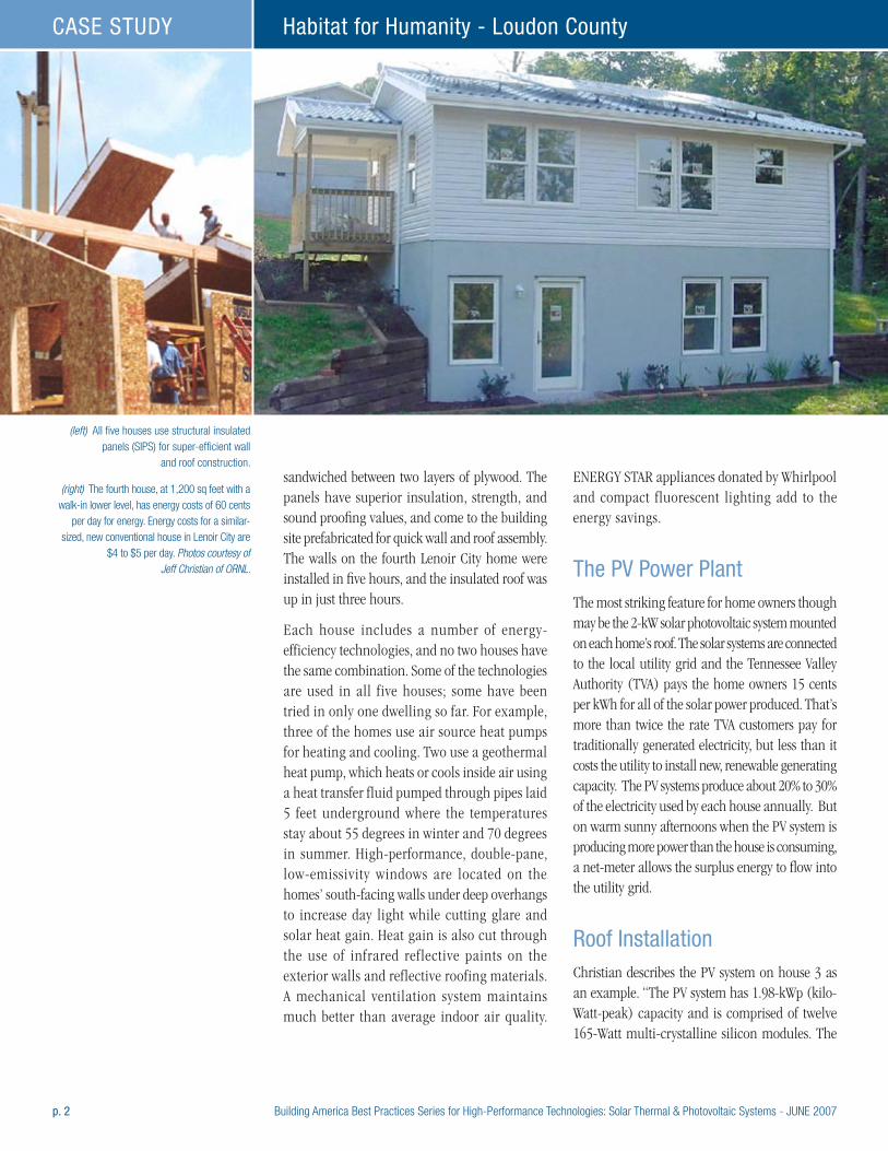
p. 2 Building America Best Practices Series for High-Performance Technologies: Solar Thermal & Photovoltaic Systems - JUNE 2007
Habitat for Humanity - Loudon CountyCASE STUDY
sandwiched between two layers of plywood. The panels have superior insulation, strength, and sound proofing values, and come to the building site prefabricated for quick wall and roof assembly. The walls on the fourth Lenoir City home were installed in five hours, and the insulated roof was up in just three hours.
Each house includes a number of energy- efficiency technologies, and no two houses have the same combination. Some of the technologies are used in all five houses; some have been tried in only one dwelling so far. For example, three of the homes use air source heat pumps for heating and cooling. Two use a geothermal heat pump, which heats or cools inside air using a heat transfer fluid pumped through pipes laid 5 feet underground where the temperatures stay about 55 degrees in winter and 70 degrees in summer. High-performance, double-pane, low-emissivity windows are located on the homes’ south-facing walls under deep overhangs to increase day light while cutting glare and solar heat gain. Heat gain is also cut through the use of infrared reflective paints on the exterior walls and reflective roofing materials. A mechanical ventilation system maintains much better than average indoor air quality.
ENERGY STAR appliances donated by Whirlpool and compact fluorescent lighting add to the energy savings.
The PV Power PlantThe most striking feature for home owners though may be the 2-kW solar photovoltaic system mounted on each home’s roof. The solar systems are connected to the local utility grid and the Tennessee Valley Authority (TVA) pays the home owners 15 cents per kWh for all of the solar power produced. That’s more than twice the rate TVA customers pay for traditionally generated electricity, but less than it costs the utility to install new, renewable generating capacity. The PV systems produce about 20% to 30% of the electricity used by each house annually. But on warm sunny afternoons when the PV system is producing more power than the house is consuming, a net-meter allows the surplus energy to flow into the utility grid.
Roof InstallationChristian describes the PV system on house 3 as an example. “The PV system has 1.98-kWp (kilo-Watt-peak) capacity and is comprised of twelve 165-Watt multi-crystalline silicon modules. The
(left) All five houses use structural insulated panels (SIPS) for super-efficient wall
and roof construction.
(right) The fourth house, at 1,200 sq feet with a walk-in lower level, has energy costs of 60 cents
per day for energy. Energy costs for a similar-sized, new conventional house in Lenoir City are
$4 to $5 per day. Photos courtesy of Jeff Christian of ORNL.
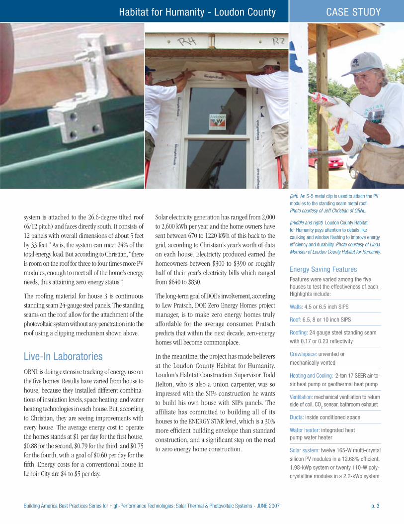
Building America Best Practices Series for High-Performance Technologies: Solar Thermal & Photovoltaic Systems - JUNE 2007 p. 3
Habitat for Humanity - Loudon County CASE STUDY
system is attached to the 26.6-degree tilted roof (6/12 pitch) and faces directly south. It consists of 12 panels with overall dimensions of about 5 feet by 33 feet.” As is, the system can meet 24% of the total energy load. But according to Christian, “there is room on the roof for three to four times more PV modules, enough to meet all of the home’s energy needs, thus attaining zero energy status.”
The roofing material for house 3 is continuous standing seam 24-gauge steel panels. The standing seams on the roof allow for the attachment of the photovoltaic system without any penetration into the roof using a clipping mechanism shown above.
Live-In LaboratoriesORNL is doing extensive tracking of energy use on the five homes. Results have varied from house to house, because they installed different combina-tions of insulation levels, space heating, and water heating technologies in each house. But, according to Christian, they are seeing improvements with every house. The average energy cost to operate the homes stands at $1 per day for the first house, $0.88 for the second, $0.79 for the third, and $0.75 for the fourth, with a goal of $0.60 per day for the fifth. Energy costs for a conventional house in Lenoir City are $4 to $5 per day.
Solar electricity generation has ranged from 2,000 to 2,600 kWh per year and the home owners have sent between 670 to 1220 kWh of this back to the grid, according to Christian’s year’s worth of data on each house. Electricity produced earned the homeowners between $300 to $390 or roughly half of their year’s electricity bills which ranged from $640 to $830.
The long-term goal of DOE’s involvement, according to Lew Pratsch, DOE Zero Energy Homes project manager, is to make zero energy homes truly affordable for the average consumer. Pratsch predicts that within the next decade, zero-energy homes will become commonplace.
In the meantime, the project has made believers at the Loudon County Habitat for Humanity. Loudon’s Habitat Construction Supervisor Todd Helton, who is also a union carpenter, was so impressed with the SIPs construction he wants to build his own house with SIPs panels. The affiliate has committed to building all of its houses to the ENERGY STAR level, which is a 30% more efficient building envelope than standard construction, and a significant step on the road to zero energy home construction.
(left) An S-5 metal clip is used to attach the PV modules to the standing seam metal roof. Photo courtesy of Jeff Christian of ORNL.
(middle and right) Loudon County Habitat for Humanity pays attention to details like caulking and window flashing to improve energy efficiency and durability. Photo courtesy of Linda Morrison of Loudon County Habitat for Humanity.
Energy Saving FeaturesFeatures were varied among the five houses to test the effectiveness of each. Highlights include:
Walls: 4.5 or 6.5 inch SIPS
Roof: 6.5, 8 or 10 inch SIPS
Roofing: 24 gauge steel standing seam
with 0.17 or 0.23 reflectivity
Crawlspace: unvented or
mechanically vented
Heating and Cooling: 2-ton 17 SEER air-to-
air heat pump or geothermal heat pump
Ventilation: mechanical ventilation to return side of coil, CO2 sensor, bathroom exhaust
Ducts: inside conditioned space
Water heater: integrated heat pump water heater
Solar system: twelve 165-W multi-crystal
silicon PV modules in a 12.68% efficient,
1.98-kWp system or twenty 110-W poly-
crystalline modules in a 2.2-kWp system
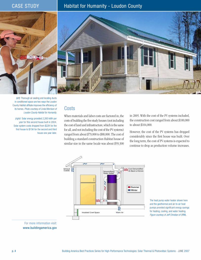
p. 4 Building America Best Practices Series for High-Performance Technologies: Solar Thermal & Photovoltaic Systems - JUNE 2007
Habitat for Humanity - Loudon CountyCASE STUDY
CostsWhen materials and labor costs are factored in, the costs of building the five study houses (not including the cost of land and infrastructure, which is the same for all, and not including the cost of the PV systems) ranged from about $79,000 to $88,000. The cost of building a standard construction Habitat house of similar size in the same locale was about $59,300
in 2005. With the cost of the PV systems included, the construction cost ranged from about $100,000 to about $104,000.
However, the cost of the PV systems has dropped considerably since the first house was built. Over the long term, the cost of PV systems is expected to continue to drop as production volume increases.
(left) Thorough air sealing and locating ducts in conditioned space are two ways the Loudon
County Habitat affiliate improves the efficiency of its homes. Photo courtesy of Linda Morrison of
Loudon County Habitat for Humanity.
(right) Solar energy provided 2,260 kWh per year for this second house built in 2004.
Solar system costs dropped from $22K for the first house to $15K for the second and third
house one year later.
For more information visit: www.buildingamerica.gov
The heat pump water heater shown here and the geothermal and air-to-air heat pumps provided significant energy savings for heating, cooling, and water heating. Figure courtesy of Jeff Christian of ORNL.
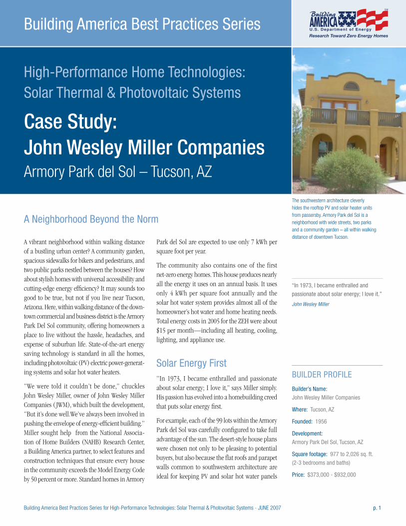
Building America Best Practices Series for High-Performance Technologies: Solar Thermal & Photovoltaic Systems - JUNE 2007 p. 1
High-Performance Home Technologies: Solar Thermal & Photovoltaic Systems
Case Study: John Wesley Miller Companies Armory Park del Sol – Tucson, AZ
Building America Best Practices Series
The southwestern architecture cleverly hides the rooftop PV and solar heater units from passersby. Armory Park del Sol is a neighborhood with wide streets, two parks and a community garden – all within walking distance of downtown Tucson.
A vibrant neighborhood within walking distance of a bustling urban center? A community garden, spacious sidewalks for bikers and pedestrians, and two public parks nestled between the houses? How about stylish homes with universal accessibility and cutting-edge energy efficiency? It may sounds too good to be true, but not if you live near Tucson, Arizona. Here, within walking distance of the down-town commercial and business district is the Armory Park Del Sol community, offering homeowners a place to live without the hassle, headaches, and expense of suburban life. State-of-the-art energy saving technology is standard in all the homes, including photovoltaic (PV) electric power-generat-ing systems and solar hot water heaters.
“We were told it couldn’t be done,” chuckles John Wesley Miller, owner of John Wesley Miller Companies ( JWM), which built the development, “But it’s done well.We’ve always been involved in pushing the envelope of energy-efficient building.” Miller sought help from the National Associa-tion of Home Builders (NAHB) Research Center, a Building America partner, to select features and construction techniques that ensure every house in the community exceeds the Model Energy Code by 50 percent or more. Standard homes in Armory
Park del Sol are expected to use only 7 kWh per square foot per year.
The community also contains one of the first net-zero energy homes. This house produces nearly all the energy it uses on an annual basis. It uses only 4 kWh per square foot annually and the solar hot water system provides almost all of the homeowner’s hot water and home heating needs. Total energy costs in 2005 for the ZEH were about $15 per month—including all heating, cooling, lighting, and appliance use.
Solar Energy First“In 1973, I became enthralled and passionate about solar energy; I love it,” says Miller simply. His passion has evolved into a homebuilding creed that puts solar energy first.
For example, each of the 99 lots within the Armory Park del Sol was carefully configured to take full advantage of the sun. The desert-style house plans were chosen not only to be pleasing to potential buyers, but also because the flat roofs and parapet walls common to southwestern architecture are ideal for keeping PV and solar hot water panels
“In 1973, I became enthralled and
passionate about solar energy; I love it.” John Wesley Miller
BUILDER PROFILE
Builder’s Name:
John Wesley Miller Companies
Where: Tucson, AZ
Founded: 1956
Development:
Armory Park Del Sol, Tucson, AZ
Square footage: 977 to 2,026 sq. ft.
(2-3 bedrooms and baths)
Price: $373,000 - $932,000
A Neighborhood Beyond the Norm
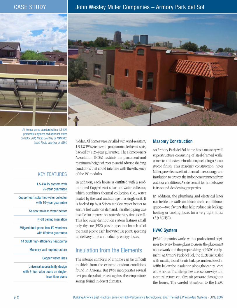
p. 2 Building America Best Practices Series for High-Performance Technologies: Solar Thermal & Photovoltaic Systems - JUNE 2007
John Wesley Miller Companies – Armory Park del SolCASE STUDY
hidden. All homes were installed with wind-resistant, 1.5-kW PV systems with programmable thermostats, backed by a 25-year guarantee. The Homeowners Association (HOA) restricts the placement and maximum height of trees to avoid adverse shading conditions that could interfere with the efficiency of the PV modules.
In addition, each house is outfitted with a roof-mounted Copperheart solar hot water collector, which combines thermal collection (i.e., water heated by the sun) and storage in a single unit. It is backed up by a Seisco tankless water heater to ensure hot water on demand. Parallel piping was installed to improve hot water delivery time as well. This hot water distribution system features small polyethylene (PEX) plastic pipes that branch off of the main pipe to each hot water use point, speeding up delivery time and reducing energy losses.
Insulation from the ElementsThe interior comforts of a home can be difficult to shield from the extreme outdoor conditions found in Arizona. But JWM incorporates several best practices that protect against the temperature swings found in desert climates.
Masonry Construction
An Armory Park del Sol home has a masonry wall superstructure consisting of steel-framed walls, concrete, and exterior insulation, including a 3-coat stucco finish. This masonry construction, notes Miller, provides excellent thermal mass storage and insulation to protect the indoor environment from outdoor conditions. A side benefit for homebuyers is its sound-deadening properties.
In addition, the plumbing and electrical lines run inside the walls and ducts are in conditioned space—two factors that help reduce air leakage heating or cooling losses for a very tight house (2.9 ACH50).
HVAC System
JWM Companies works with a professional engi-neer to review house plans to assess the placement of ductwork and the proper sizing of HVAC equip-ment. At Armory Park del Sol, the ducts are sealed with mastic, tested for air leakage, and enclosed in soffits below the insulation along the central core of the house. Transfer grilles across doorways and a central return equalize air pressure throughout the house. The careful attention to the HVAC
All homes come standard with a 1.5-kW photovoltaic system and solar hot water
collector. (left) Photo courtesy of NAHBRC. (right) Photo courtesy of JWM.
KEY FEATURES
1.5-kW PV system with
25-year guarantee
Copperheart solar hot water collector
with 10-year guarantee
Seisco tankless water heater
R-38 ceiling insulation
Milgard dual-pane, low-E2 windows
with lifetime guarantee
14 SEER high-efficiency heat pump
Masonry wall superstructure
Copper water lines
Universal accessibility design
with 3-foot-wide doors on single-
level floor plans
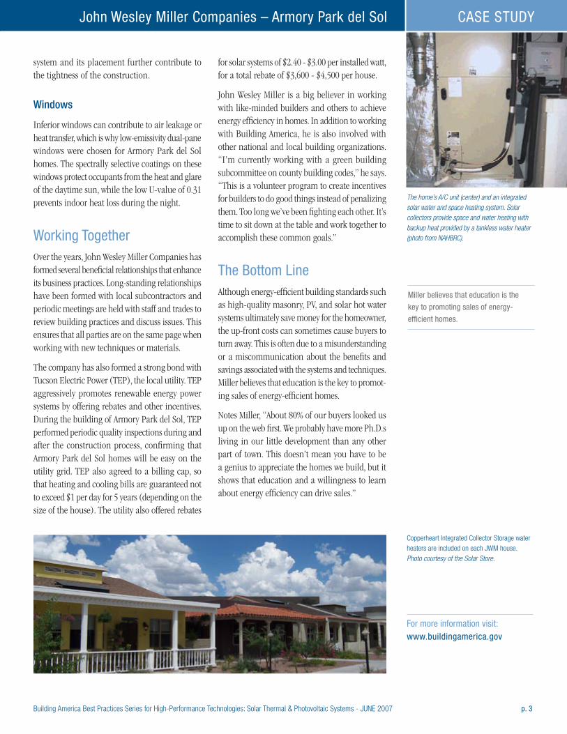
Building America Best Practices Series for High-Performance Technologies: Solar Thermal & Photovoltaic Systems - JUNE 2007 p. 3
John Wesley Miller Companies – Armory Park del Sol CASE STUDY
system and its placement further contribute to the tightness of the construction.
Windows
Inferior windows can contribute to air leakage or heat transfer, which is why low-emissivity dual-pane windows were chosen for Armory Park del Sol homes. The spectrally selective coatings on these windows protect occupants from the heat and glare of the daytime sun, while the low U-value of 0.31 prevents indoor heat loss during the night.
Working TogetherOver the years, John Wesley Miller Companies has formed several beneficial relationships that enhance its business practices. Long-standing relationships have been formed with local subcontractors and periodic meetings are held with staff and trades to review building practices and discuss issues. This ensures that all parties are on the same page when working with new techniques or materials.
The company has also formed a strong bond with Tucson Electric Power (TEP), the local utility. TEP aggressively promotes renewable energy power systems by offering rebates and other incentives. During the building of Armory Park del Sol, TEP performed periodic quality inspections during and after the construction process, confirming that Armory Park del Sol homes will be easy on the utility grid. TEP also agreed to a billing cap, so that heating and cooling bills are guaranteed not to exceed $1 per day for 5 years (depending on the size of the house). The utility also offered rebates
for solar systems of $2.40 - $3.00 per installed watt, for a total rebate of $3,600 - $4,500 per house.
John Wesley Miller is a big believer in working with like-minded builders and others to achieve energy efficiency in homes. In addition to working with Building America, he is also involved with other national and local building organizations. “I’m currently working with a green building subcommittee on county building codes,” he says. “This is a volunteer program to create incentives for builders to do good things instead of penalizing them. Too long we’ve been fighting each other. It’s time to sit down at the table and work together to accomplish these common goals.”
The Bottom LineAlthough energy-efficient building standards such as high-quality masonry, PV, and solar hot water systems ultimately save money for the homeowner, the up-front costs can sometimes cause buyers to turn away. This is often due to a misunderstanding or a miscommunication about the benefits and savings associated with the systems and techniques. Miller believes that education is the key to promot-ing sales of energy-efficient homes.
Notes Miller, “About 80% of our buyers looked us up on the web first. We probably have more Ph.D.s living in our little development than any other part of town. This doesn’t mean you have to be a genius to appreciate the homes we build, but it shows that education and a willingness to learn about energy efficiency can drive sales.”
The home’s A/C unit (center) and an integrated solar water and space heating system. Solar collectors provide space and water heating with backup heat provided by a tankless water heater (photo from NAHBRC).
Miller believes that education is the
key to promoting sales of energy-
efficient homes.
For more information visit: www.buildingamerica.gov
Copperheart Integrated Collector Storage water heaters are included on each JWM house. Photo courtesy of the Solar Store.
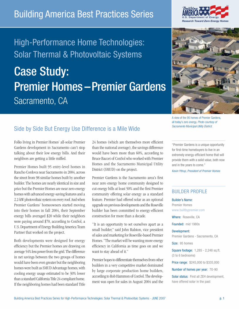
Building America Best Practices Series for High-Performance Technologies: Solar Thermal & Photovoltaic Systems - JUNE 2007 p. 1
High-Performance Home Technologies: Solar Thermal & Photovoltaic Systems
Case Study: Premier Homes – Premier Gardens Sacramento, CA
Building America Best Practices Series
Folks living in Premier Homes’ all-solar Premier Gardens development in Sacramento can’t stop talking about their low energy bills. And their neighbors are getting a little miffed.
Premier Homes built 95 entry-level homes in Rancho Cordova near Sacramento in 2004, across the street from 98 similar homes built by another builder. The homes are nearly identical in size and price but the Premier Homes are near zero energy homes with advanced energy-saving features and a 2.2-kW photovoltaic system on every roof. And when Premier Gardens’ homeowners started moving into their homes in fall 2004, their September energy bills averaged $20 while their neighbors were paying around $70, according to ConSol, a U.S. Department of Energy Building America Team Partner that worked on the project.
Both developments were designed for energy efficiency but the Premier homes are drawing on average 54% less power from the grid. The difference in net savings between the two groups of homes would have been even greater but the neighboring homes were built as SMUD Advantage homes, with cooling energy usage estimated to be 30% lower than a standard California Title 24-compliant home. If the neighboring homes had been standard Title
24 homes (which are themselves more efficient than the national average), the savings difference would have been more than 60%, according to Bruce Baccei of ConSol who worked with Premier Homes and the Sacramento Municipal Utility District (SMUD) on the project.
Premier Gardens is the Sacramento area’s first near zero energy home community designed to cut energy bills at least 50% and the first Premier community offering solar energy as a standard feature. Premier had offered solar as an optional upgrade on previous developments and the Roseville builder has been committed to energy-efficient construction for more than a decade.
“It is an opportunity to set ourselves apart as a small builder,” said John Ralston, vice president of sales and marketing for Roseville-based Premier Homes. “The market will be wanting more energy efficiency in California as time goes on and we want to stay ahead of it.”
Premier hopes to differentiate themselves from other builders in a very competitive market dominated by large corporate production home builders, according to Rob Hammon of ConSol. The develop-ment was open for sales in August 2004 and the
“Premier Gardens is a unique opportunity
for first-time homebuyers to live in an
extremely energy-efficient home that will
provide them with a solid value, both now
and in the years to come.” Kevin Yttrup, President of Premier Homes
BUILDER PROFILE
Builder’s Name:
Premier Homes
www.builtbypremier.com
Where: Roseville, CA
Founded: mid 1980s
Development:
Premier Gardens - Sacramento, CA
Size: 95 homes
Square footage: 1,285 - 2,248 sq.ft.
(3 to 6 bedrooms)
Price range: $245,000 to $335,000
Number of homes per year: 70-90
Solar status: First all ZEH development,
have offered solar in the past
A view of the 95 homes of Premier Gardens, all today’s zero energy. Photo courtesy of Sacramento Municipal Utility District.Side by Side But Energy Use Difference is a Mile Wide
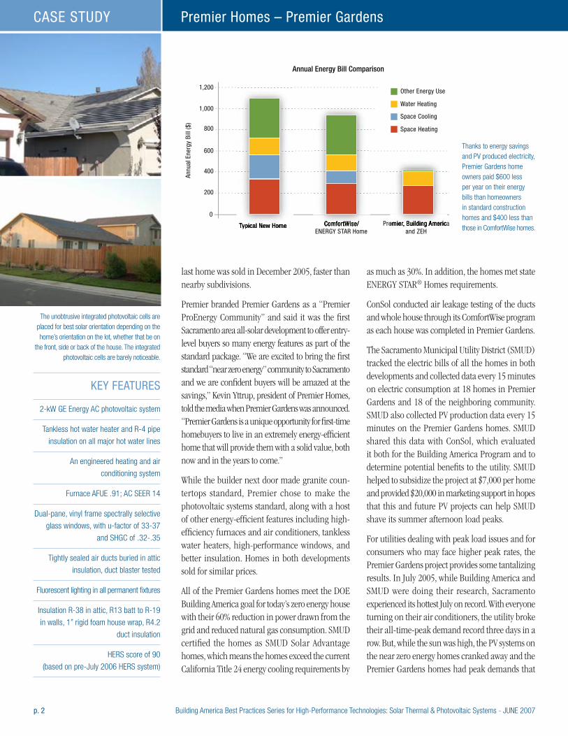
p. 2 Building America Best Practices Series for High-Performance Technologies: Solar Thermal & Photovoltaic Systems - JUNE 2007
Premier Homes – Premier GardensCASE STUDY
last home was sold in December 2005, faster than nearby subdivisions.
Premier branded Premier Gardens as a “Premier ProEnergy Community” and said it was the first Sacramento area all-solar development to offer entry-level buyers so many energy features as part of the standard package. “We are excited to bring the first standard “near zero energy” community to Sacramento and we are confident buyers will be amazed at the savings,” Kevin Yttrup, president of Premier Homes, told the media when Premier Gardens was announced. “Premier Gardens is a unique opportunity for first-time homebuyers to live in an extremely energy-efficient home that will provide them with a solid value, both now and in the years to come.”
While the builder next door made granite coun-tertops standard, Premier chose to make the photovoltaic systems standard, along with a host of other energy-efficient features including high-efficiency furnaces and air conditioners, tankless water heaters, high-performance windows, and better insulation. Homes in both developments sold for similar prices.
All of the Premier Gardens homes meet the DOE Building America goal for today’s zero energy house with their 60% reduction in power drawn from the grid and reduced natural gas consumption. SMUD certified the homes as SMUD Solar Advantage homes, which means the homes exceed the current California Title 24 energy cooling requirements by
as much as 30%. In addition, the homes met state ENERGY STAR® Homes requirements.
ConSol conducted air leakage testing of the ducts and whole house through its ComfortWise program as each house was completed in Premier Gardens.
The Sacramento Municipal Utility District (SMUD) tracked the electric bills of all the homes in both developments and collected data every 15 minutes on electric consumption at 18 homes in Premier Gardens and 18 of the neighboring community. SMUD also collected PV production data every 15 minutes on the Premier Gardens homes. SMUD shared this data with ConSol, which evaluated it both for the Building America Program and to determine potential benefits to the utility. SMUD helped to subsidize the project at $7,000 per home and provided $20,000 in marketing support in hopes that this and future PV projects can help SMUD shave its summer afternoon load peaks.
For utilities dealing with peak load issues and for consumers who may face higher peak rates, the Premier Gardens project provides some tantalizing results. In July 2005, while Building America and SMUD were doing their research, Sacramento experienced its hottest July on record. With everyone turning on their air conditioners, the utility broke their all-time-peak demand record three days in a row. But, while the sun was high, the PV systems on the near zero energy homes cranked away and the Premier Gardens homes had peak demands that
KEY FEATURES
2-kW GE Energy AC photovoltaic system
Tankless hot water heater and R-4 pipe
insulation on all major hot water lines
An engineered heating and air
conditioning system
Furnace AFUE .91; AC SEER 14
Dual-pane, vinyl frame spectrally selective
glass windows, with u-factor of 33-37
and SHGC of .32-.35
Tightly sealed air ducts buried in attic
insulation, duct blaster tested
Fluorescent lighting in all permanent fixtures
Insulation R-38 in attic, R13 batt to R-19
in walls, 1” rigid foam house wrap, R4.2
duct insulation
HERS score of 90
(based on pre-July 2006 HERS system)
The unobtrusive integrated photovoltaic cells are placed for best solar orientation depending on the home’s orientation on the lot, whether that be on
the front, side or back of the house. The integrated photovoltaic cells are barely noticeable.
0
Typical New Home ComfortWise/ENERGY STAR Home
Premier, Building Americaand ZEH
Other Energy Use
Water Heating
Space Cooling
Space Heating
Annu
al E
nerg
y Bi
ll ($
)200
400
600
800
1,000
1,200
Annual Energy Bill Comparison
Thanks to energy savings and PV produced electricity, Premier Gardens home owners paid $600 less per year on their energy bills than homeowners in standard construction homes and $400 less than those in ComfortWise homes.

Building America Best Practices Series for High-Performance Technologies: Solar Thermal & Photovoltaic Systems - JUNE 2007 p. 3
Premier Homes – Premier Gardens CASE STUDY
were 75% lower than their neighbors. “The ability of solar to level out air conditioning-driven peak demand makes it a desirable investment for utilities and for consumers who want to help decrease the likelihood of rolling blackouts and sky-high utility prices,” said Baccei.
“Zero Energy Homes provide multiple bene-fits—lower energy bills for the homeowner and reduced energy demand on hot summer days when electricity is more expensive and the power grid most utilized,” said Paul Bender, SMUD manager of power production.
Solar SystemThe 2.2-kW photovoltaic system installed on Premier Gardens’ homes is an integrated tile PV product manufactured by GE Energy called Gecko modules. The tiles are similar in dimension to cement roof tiles and lay on the roof shingle fashion to blend with surrounding roofing. The system consists of 48 GT-55 modules and a SMA Sunny Boy 2500 inverter. SMUD supplied each home with a PV meter to record the solar electric system’s energy output; this figure appears on the homeowner’s monthly electric bill along with their electricity usage.
ConSol and SMUD reported in March 2006 that the PV systems were performing exceptionally well and consistently exceeding estimated kilowatt hour
production by 10% over the course of the first year. The homes produced about 3,330 kWh per year out of a total average of 7,007 kWh consumed per household between September 2004 and September 2005.
The systems were installed by an installation company founded by Premier Homes’ owners. Premier liked the aesthetics of the roof-integrated PV panels and found homebuyer acceptance was high. Some home builders are hesitant to install PV systems on the fronts of homes. Others believe that the visibility of PV systems can be desirable for home buyers who want to “show off” their photovoltaic systems.
Energy-Efficient Features and Innovations“The first step in designing a near zero energy home is to significantly reduce the home’s overall energy use. This enables the home builder to install a smaller, less expensive PV system to meet the home’s electrical needs,” said Rob Hammon of ConSol.
Building America, through its team leader ConSol, provided an energy analysis to help Premier select energy-efficient measures for the five house plans featured in the community. Each home is equipped with a high-efficiency .91 AFUE furnace and a correctly sized SEER 14 air conditioner. Ducts are
-1.0012 1 2 3 4 5AM PM
6 7 8 9 10 11 12 1 2 3 4 5 6 7 8 9 10 11
500
1,000
1,500
2,000
2,500
3,000
-0.5
-0.0
0.5
1.0
1.5
2.0
2.5
3.0
3.5 kW
Avg. High Temp = 98°F
Average 15 Minute Interval Peak Demand ZEH vs. Non-ZEH July, 2005
Avg. Min Temp = 65°FSystem Peak MWAverage of ZEH Net Grid Load (kW)Average of Power Produced by PV (kW)Average of Non-ZEH Net Grid Load (kW)
Selling Solar
Some of Premier’s most dedicated solar fans
are its sales staff. “I am their walking, living,
breathing advertisement for solar out here,”
said Sheri Gage, sales manager and owner
of one of the first solar homes completed at
Premier Meadows, a 65-unit Premier Homes
development at Live Oak 50 miles north of
Sacramento.
“I’ve been in since December 2005, and my
electric bills have ranged from a high of $70
to a low of $1.60 per month (for a 1,990 sq
ft home),” said Gage. “People have been
walking into my sales office who are paying
between $250 and $800 a month on their
electric bills,” said Gage.
PG&E has raised the rates several times
in the last two years. In August 2006, they
announced another rate increase in Septem-
ber with two more likely to follow.”
To show home buyers they have a choice,
Premier Homes has run a very successful
campaign advertising $30 a month bills. “We
did an analysis of the Premier Gardens homes
for a 9-month period in 2005. All 95 homes
averaged $30 per month,” said Don Rives,
sales manager at Premier Homes Premier
Gardens and now Premier Bay Drive Estates,
another all solar Premier development.
A look at peak demand in July shows how much lower the near zero energy home’s demand is than that of nearby energy-efficient houses without PV.
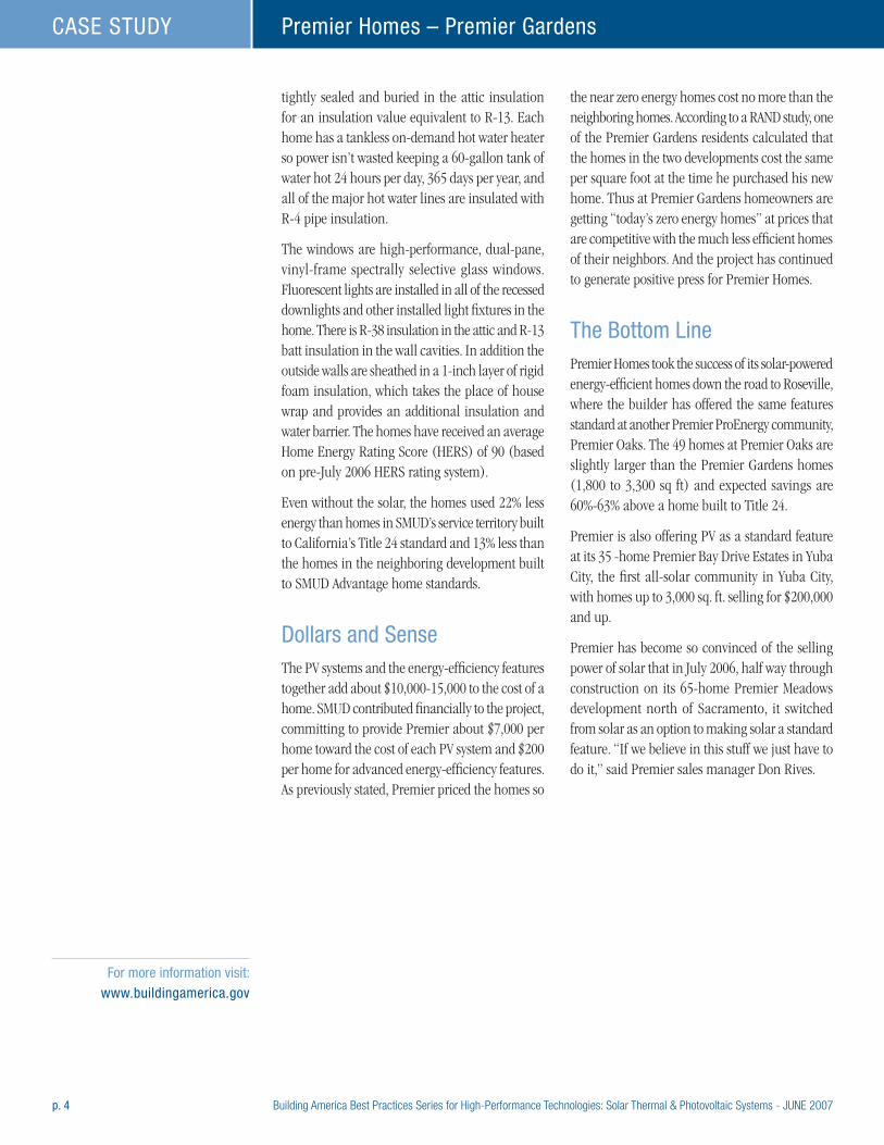
p. 4 Building America Best Practices Series for High-Performance Technologies: Solar Thermal & Photovoltaic Systems - JUNE 2007
Premier Homes – Premier GardensCASE STUDY
tightly sealed and buried in the attic insulation for an insulation value equivalent to R-13. Each home has a tankless on-demand hot water heater so power isn’t wasted keeping a 60-gallon tank of water hot 24 hours per day, 365 days per year, and all of the major hot water lines are insulated with R-4 pipe insulation.
The windows are high-performance, dual-pane, vinyl-frame spectrally selective glass windows. Fluorescent lights are installed in all of the recessed downlights and other installed light fixtures in the home. There is R-38 insulation in the attic and R-13 batt insulation in the wall cavities. In addition the outside walls are sheathed in a 1-inch layer of rigid foam insulation, which takes the place of house wrap and provides an additional insulation and water barrier. The homes have received an average Home Energy Rating Score (HERS) of 90 (based on pre-July 2006 HERS rating system).
Even without the solar, the homes used 22% less energy than homes in SMUD’s service territory built to California’s Title 24 standard and 13% less than the homes in the neighboring development built to SMUD Advantage home standards.
Dollars and SenseThe PV systems and the energy-efficiency features together add about $10,000-15,000 to the cost of a home. SMUD contributed financially to the project, committing to provide Premier about $7,000 per home toward the cost of each PV system and $200 per home for advanced energy-efficiency features. As previously stated, Premier priced the homes so
the near zero energy homes cost no more than the neighboring homes. According to a RAND study, one of the Premier Gardens residents calculated that the homes in the two developments cost the same per square foot at the time he purchased his new home. Thus at Premier Gardens homeowners are getting “today’s zero energy homes” at prices that are competitive with the much less efficient homes of their neighbors. And the project has continued to generate positive press for Premier Homes.
The Bottom LinePremier Homes took the success of its solar-powered energy-efficient homes down the road to Roseville, where the builder has offered the same features standard at another Premier ProEnergy community, Premier Oaks. The 49 homes at Premier Oaks are slightly larger than the Premier Gardens homes (1,800 to 3,300 sq ft) and expected savings are 60%-63% above a home built to Title 24.
Premier is also offering PV as a standard feature at its 35 -home Premier Bay Drive Estates in Yuba City, the first all-solar community in Yuba City, with homes up to 3,000 sq. ft. selling for $200,000 and up.
Premier has become so convinced of the selling power of solar that in July 2006, half way through construction on its 65-home Premier Meadows development north of Sacramento, it switched from solar as an option to making solar a standard feature. “If we believe in this stuff we just have to do it,” said Premier sales manager Don Rives.
For more information visit: www.buildingamerica.gov
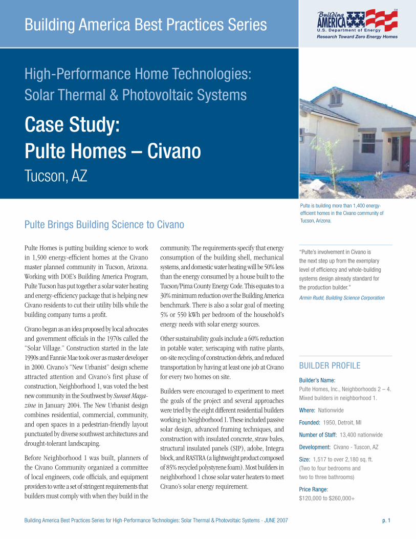
Building America Best Practices Series for High-Performance Technologies: Solar Thermal & Photovoltaic Systems - JUNE 2007 p. 1
High-Performance Home Technologies: Solar Thermal & Photovoltaic Systems
Case Study: Pulte Homes – Civano Tucson, AZ
Building America Best Practices Series
Pulte Homes is putting building science to work in 1,500 energy-efficient homes at the Civano master planned community in Tucson, Arizona. Working with DOE’s Building America Program, Pulte Tucson has put together a solar water heating and energy-efficiency package that is helping new Civano residents to cut their utility bills while the building company turns a profit.
Civano began as an idea proposed by local advocates and government officials in the 1970s called the “Solar Village.” Construction started in the late 1990s and Fannie Mae took over as master developer in 2000. Civano’s “New Urbanist” design scheme attracted attention and Civano’s first phase of construction, Neighborhood 1, was voted the best new community in the Southwest by Sunset Maga-zine in January 2004. The New Urbanist design combines residential, commercial, community, and open spaces in a pedestrian-friendly layout punctuated by diverse southwest architectures and drought-tolerant landscaping.
Before Neighborhood 1 was built, planners of the Civano Community organized a committee of local engineers, code officials, and equipment providers to write a set of stringent requirements that builders must comply with when they build in the
community. The requirements specify that energy consumption of the building shell, mechanical systems, and domestic water heating will be 50% less than the energy consumed by a house built to the Tucson/Pima County Energy Code. This equates to a 30% minimum reduction over the Building America benchmark. There is also a solar goal of meeting 5% or 550 kWh per bedroom of the household’s energy needs with solar energy sources.
Other sustainability goals include a 60% reduction in potable water; xeriscaping with native plants, on-site recycling of construction debris, and reduced transportation by having at least one job at Civano for every two homes on site.
Builders were encouraged to experiment to meet the goals of the project and several approaches were tried by the eight different residential builders working in Neighborhood 1. These included passive solar design, advanced framing techniques, and construction with insulated concrete, straw bales, structural insulated panels (SIP), adobe, Integra block, and RASTRA (a lightweight product composed of 85% recycled polystyrene foam). Most builders in neighborhood 1 chose solar water heaters to meet Civano’s solar energy requirement.
“Pulte’s involvement in Civano is
the next step up from the exemplary
level of efficiency and whole-building
systems design already standard for
the production builder.” Armin Rudd, Building Science Corporation
BUILDER PROFILE
Builder’s Name:
Pulte Homes, Inc., Neighborhoods 2 – 4.
Mixed builders in neighborhood 1.
Where: Nationwide
Founded: 1950, Detroit, MI
Number of Staff: 13,400 nationwide
Development: Civano - Tuscon, AZ
Size: 1,517 to over 2,180 sq. ft.
(Two to four bedrooms and
two to three bathrooms)
Price Range:
$120,000 to $260,000+
Pulte is building more than 1,400 energy-efficient homes in the Civano community of Tucson, Arizona.Pulte Brings Building Science to Civano
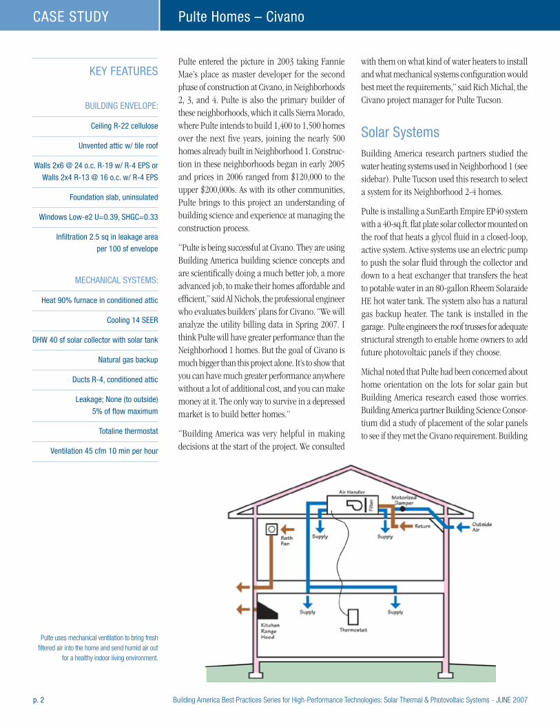
p. 2 Building America Best Practices Series for High-Performance Technologies: Solar Thermal & Photovoltaic Systems - JUNE 2007
Pulte Homes – CivanoCASE STUDY
Pulte entered the picture in 2003 taking Fannie Mae’s place as master developer for the second phase of construction at Civano, in Neighborhoods 2, 3, and 4. Pulte is also the primary builder of these neighborhoods, which it calls Sierra Morado, where Pulte intends to build 1,400 to 1,500 homes over the next five years, joining the nearly 500 homes already built in Neighborhood 1. Construc-tion in these neighborhoods began in early 2005 and prices in 2006 ranged from $120,000 to the upper $200,000s. As with its other communities, Pulte brings to this project an understanding of building science and experience at managing the construction process.
“Pulte is being successful at Civano. They are using Building America building science concepts and are scientifically doing a much better job, a more advanced job, to make their homes affordable and efficient,” said Al Nichols, the professional engineer who evaluates builders’ plans for Civano. “We will analyze the utility billing data in Spring 2007. I think Pulte will have greater performance than the Neighborhood 1 homes. But the goal of Civano is much bigger than this project alone. It’s to show that you can have much greater performance anywhere without a lot of additional cost, and you can make money at it. The only way to survive in a depressed market is to build better homes.”
“Building America was very helpful in making decisions at the start of the project. We consulted
with them on what kind of water heaters to install and what mechanical systems configuration would best meet the requirements,” said Rich Michal, the Civano project manager for Pulte Tucson.
Solar SystemsBuilding America research partners studied the water heating systems used in Neighborhood 1 (see sidebar). Pulte Tucson used this research to select a system for its Neighborhood 2-4 homes.
Pulte is installing a SunEarth Empire EP40 system with a 40-sq.ft. flat plate solar collector mounted on the roof that heats a glycol fluid in a closed-loop, active system. Active systems use an electric pump to push the solar fluid through the collector and down to a heat exchanger that transfers the heat to potable water in an 80-gallon Rheem Solaraide HE hot water tank. The system also has a natural gas backup heater. The tank is installed in the garage. Pulte engineers the roof trusses for adequate structural strength to enable home owners to add future photovoltaic panels if they choose.
Michal noted that Pulte had been concerned about home orientation on the lots for solar gain but Building America research eased those worries. Building America partner Building Science Consor-tium did a study of placement of the solar panels to see if they met the Civano requirement. Building
KEY FEATURES
BUILDING ENVELOPE:
Ceiling R-22 cellulose
Unvented attic w/ tile roof
Walls 2x6 @ 24 o.c. R-19 w/ R-4 EPS or
Walls 2x4 R-13 @ 16 o.c. w/ R-4 EPS
Foundation slab, uninsulated
Windows Low-e2 U=0.39, SHGC=0.33
Infiltration 2.5 sq in leakage area
per 100 sf envelope
MECHANICAL SYSTEMS:
Heat 90% furnace in conditioned attic
Cooling 14 SEER
DHW 40 sf solar collector with solar tank
Natural gas backup
Ducts R-4, conditioned attic
Leakage; None (to outside)
5% of flow maximum
Totaline thermostat
Ventilation 45 cfm 10 min per hour
Pulte uses mechanical ventilation to bring fresh filtered air into the home and send humid air out
for a healthy indoor living environment.
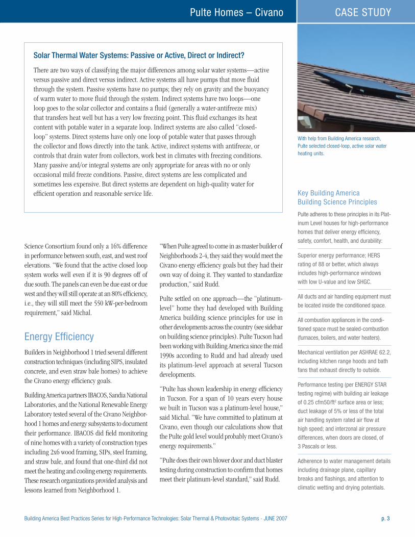
Building America Best Practices Series for High-Performance Technologies: Solar Thermal & Photovoltaic Systems - JUNE 2007 p. 3
Pulte Homes – Civano CASE STUDY
Science Consortium found only a 16% difference in performance between south, east, and west roof elevations. “We found that the active closed loop system works well even if it is 90 degrees off of due south. The panels can even be due east or due west and they will still operate at an 80% efficiency, i.e., they will still meet the 550 kW-per-bedroom requirement,” said Michal.
Energy EfficiencyBuilders in Neighborhood 1 tried several different construction techniques (including SIPS, insulated concrete, and even straw bale homes) to achieve the Civano energy efficiency goals.
Building America partners IBACOS, Sandia National Laboratories, and the National Renewable Energy Laboratory tested several of the Civano Neighbor-hood 1 homes and energy subsystems to document their performance. IBACOS did field monitoring of nine homes with a variety of construction types including 2x6 wood framing, SIPs, steel framing, and straw bale, and found that one-third did not meet the heating and cooling energy requirements. These research organizations provided analysis and lessons learned from Neighborhood 1.
“When Pulte agreed to come in as master builder of Neighborhoods 2-4, they said they would meet the Civano energy efficiency goals but they had their own way of doing it. They wanted to standardize production,” said Rudd.
Pulte settled on one approach—the “platinum-level” home they had developed with Building America building science principles for use in other developments across the country (see sidebar on building science principles). Pulte Tucson had been working with Building America since the mid 1990s according to Rudd and had already used its platinum-level approach at several Tucson developments.
“Pulte has shown leadership in energy efficiency in Tucson. For a span of 10 years every house we built in Tucson was a platinum-level house,” said Michal. “We have committed to platinum at Civano, even though our calculations show that the Pulte gold level would probably meet Civano’s energy requirements.”
“Pulte does their own blower door and duct blaster testing during construction to confirm that homes meet their platinum-level standard,” said Rudd.
With help from Building America research, Pulte selected closed-loop, active solar water heating units.
Solar Thermal Water Systems: Passive or Active, Direct or Indirect?
There are two ways of classifying the major differences among solar water systems—active versus passive and direct versus indirect. Active systems all have pumps that move fluid through the system. Passive systems have no pumps; they rely on gravity and the buoyancy of warm water to move fluid through the system. Indirect systems have two loops—one loop goes to the solar collector and contains a fluid (generally a water-antifreeze mix) that transfers heat well but has a very low freezing point. This fluid exchanges its heat content with potable water in a separate loop. Indirect systems are also called “closed-loop” systems. Direct systems have only one loop of potable water that passes through the collector and flows directly into the tank. Active, indirect systems with antifreeze, or controls that drain water from collectors, work best in climates with freezing conditions. Many passive and/or integral systems are only appropriate for areas with no or only occasional mild freeze conditions. Passive, direct systems are less complicated and sometimes less expensive. But direct systems are dependent on high-quality water for efficient operation and reasonable service life. Key Building America
Building Science Principles
Pulte adheres to these principles in its Plat-
inum Level houses for high-performance
homes that deliver energy efficiency,
safety, comfort, health, and durability:
Superior energy performance; HERS
rating of 88 or better, which always
includes high-performance windows
with low U-value and low SHGC.
All ducts and air handling equipment must
be located inside the conditioned space.
All combustion appliances in the condi-
tioned space must be sealed-combustion
(furnaces, boilers, and water heaters).
Mechanical ventilation per ASHRAE 62.2,
including kitchen range hoods and bath
fans that exhaust directly to outside.
Performance testing (per ENERGY STAR
testing regime) with building air leakage
of 0.25 cfm50/ft2 surface area or less;
duct leakage of 5% or less of the total
air handling system rated air flow at
high speed; and interzonal air pressure
differences, when doors are closed, of
3 Pascals or less.
Adherence to water management details
including drainage plane, capillary
breaks and flashings, and attention to
climatic wetting and drying potentials.
p. 4 Building America Best Practices Series for High-Performance Technologies: Solar Thermal & Photovoltaic Systems - JUNE 2007
Pulte Homes – CivanoCASE STUDY
According to Michal, one of the biggest changes Pulte makes in construction techniques over standard practice is to place the mechanical equipment in conditioned space in the attic. “We use cathedralized insulation; in other words, we apply the insulation right up along the roof line instead of on top of the ceiling. We use a blown-in cellulose product. It is a mixture of recycled newspapers and a fire retardant. We staple a burlap type sheeting to the rafters, then blow in the insulation above the sheeting along the roof line to insulate the attic. We also apply it wet to the walls before sheetrocking; it sticks to the walls and dries in place,” said Michal.
Pulte has also chosen high-efficiency HVAC equip-ment as a standard feature in each home, including a SEER 14 air conditioner and a 90% AFUE sealed combustion gas furnace, with all ducts located inside the conditioned attic. Controlled mechanical ventilation is provided by a central fan with fresh outside filtered air provided to the air handler through a motorized damper.
Dollars and SenseBSC evaluated 11 Pulte house plans against the Building America benchmark using the Ener-gyGauge USA software and found the Pulte homes will reduce total energy costs by approximately
$500 to $850 annually.
According to Michal, the solar water heaters qualify homebuyers for pretty substantial federal and state tax credits and Pulte works with the installers to ensure that the homebuyer gets the documentation needed to qualify for their tax credits. The state of Arizona offers a solar tax credit for 25% of the cost of an approved solar device or system, up to $1,000. The homebuyer would also qualify for federal tax credits.
Those incentives could be enough to sway buyers in a competitive Tucson first-time home buyer market that was very hot in 2005 and early 2006 but has cooled considerably since.
The Bottom Line“In a really high-growth area, there is a lot of competition and a push to just get homes up and fast. You could build a cardboard box and be successful in the first-time home market here when it was really hopping. We’ve had the leadership that was committed to building to a higher standard, going to the higher level. We are motivated to go for the return customer,” said Michal. Michal, who lives at Civano, added his encouragement for builders contemplating solar. “I think it’s the future. If we want to sustain the growth in this industry, we’ve
“Pulte is being successful at Civano.
They are using Building America building
science concepts and are scientifi-
cally doing a much better job, a more
advanced job, to make their homes
affordable and efficient.” Al Nichols, professional engineer who
evaluates builders’ plans for Civano
Solar Water Heating Lessons Learned at Civano Neighborhood 1
Many of the solar collectors and related copper pipes installed in Neighborhood 1 failed or experienced excessive pitting. The collectors were part of passive, direct systems that had city water flowing through them. Building America researchers found that the city water had CO
2
and potassium levels and a nitrate/nitrite ratio just high enough to be aggressive in terms of potentially corroding and pitting copper. The copper corrosion properties of the water were theorized to be enhanced by higher temperatures.
In Neighborhoods 2, 3, and 4, Pulte chose to use an active, indirect system where the fluid circulating through the solar collector is in a closed loop and is a combination of water and nontoxic antifreeze that does not have the city water’s corrosive properties.
IBACOS, a Building America team leader, found other problems with the design of the original solar water heating systems. One problem was that pipe runs were as much as 120 feet from the collector to the tank in some homes. The Civano energy requirements have since been upgraded to require that rooftop collectors be installed within 20 feet of the storage tank.
(continued on next page)
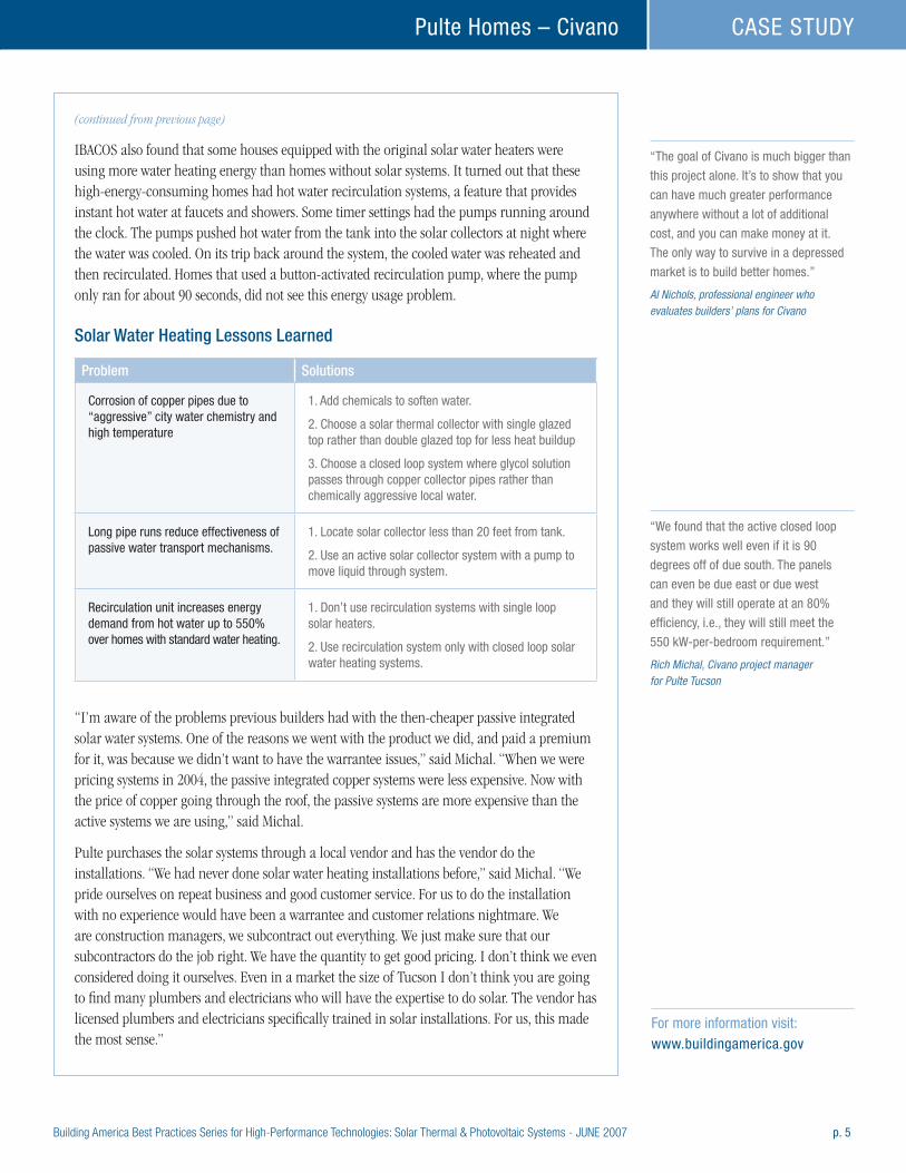
Building America Best Practices Series for High-Performance Technologies: Solar Thermal & Photovoltaic Systems - JUNE 2007 p. 5
Pulte Homes – Civano CASE STUDY
“The goal of Civano is much bigger than
this project alone. It’s to show that you
can have much greater performance
anywhere without a lot of additional
cost, and you can make money at it.
The only way to survive in a depressed
market is to build better homes.” Al Nichols, professional engineer who evaluates builders’ plans for Civano
“We found that the active closed loop
system works well even if it is 90
degrees off of due south. The panels
can even be due east or due west
and they will still operate at an 80%
efficiency, i.e., they will still meet the
550 kW-per-bedroom requirement.” Rich Michal, Civano project manager for Pulte Tucson
(continued from previous page)
IBACOS also found that some houses equipped with the original solar water heaters were using more water heating energy than homes without solar systems. It turned out that these high-energy-consuming homes had hot water recirculation systems, a feature that provides instant hot water at faucets and showers. Some timer settings had the pumps running around the clock. The pumps pushed hot water from the tank into the solar collectors at night where the water was cooled. On its trip back around the system, the cooled water was reheated and then recirculated. Homes that used a button-activated recirculation pump, where the pump only ran for about 90 seconds, did not see this energy usage problem.
Solar Water Heating Lessons Learned
Problem Solutions
Corrosion of copper pipes due to “aggressive” city water chemistry and high temperature
1. Add chemicals to soften water.
2. Choose a solar thermal collector with single glazed top rather than double glazed top for less heat buildup
3. Choose a closed loop system where glycol solution passes through copper collector pipes rather than chemically aggressive local water.
Long pipe runs reduce effectiveness of passive water transport mechanisms.
1. Locate solar collector less than 20 feet from tank.
2. Use an active solar collector system with a pump to move liquid through system.
Recirculation unit increases energy demand from hot water up to 550% over homes with standard water heating.
1. Don’t use recirculation systems with single loop solar heaters.
2. Use recirculation system only with closed loop solar water heating systems.
“I’m aware of the problems previous builders had with the then-cheaper passive integrated solar water systems. One of the reasons we went with the product we did, and paid a premium for it, was because we didn’t want to have the warrantee issues,” said Michal. “When we were pricing systems in 2004, the passive integrated copper systems were less expensive. Now with the price of copper going through the roof, the passive systems are more expensive than the active systems we are using,” said Michal.
Pulte purchases the solar systems through a local vendor and has the vendor do the installations. “We had never done solar water heating installations before,” said Michal. “We pride ourselves on repeat business and good customer service. For us to do the installation with no experience would have been a warrantee and customer relations nightmare. We are construction managers, we subcontract out everything. We just make sure that our subcontractors do the job right. We have the quantity to get good pricing. I don’t think we even considered doing it ourselves. Even in a market the size of Tucson I don’t think you are going to find many plumbers and electricians who will have the expertise to do solar. The vendor has licensed plumbers and electricians specifically trained in solar installations. For us, this made the most sense.”
For more information visit: www.buildingamerica.gov
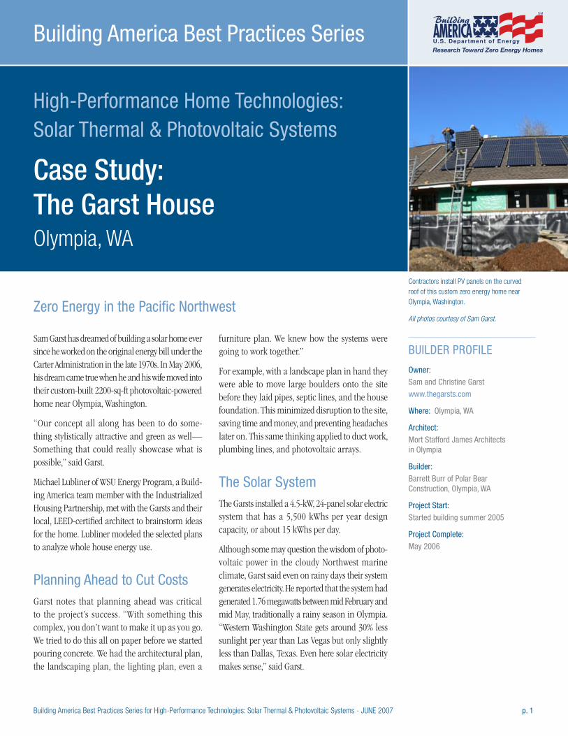
Building America Best Practices Series for High-Performance Technologies: Solar Thermal & Photovoltaic Systems - JUNE 2007 p. 1
High-Performance Home Technologies: Solar Thermal & Photovoltaic Systems
Case Study: The Garst House Olympia, WA
Building America Best Practices Series
Sam Garst has dreamed of building a solar home ever since he worked on the original energy bill under the Carter Administration in the late 1970s. In May 2006, his dream came true when he and his wife moved into their custom-built 2200-sq-ft photovoltaic-powered home near Olympia, Washington.
“Our concept all along has been to do some-thing stylistically attractive and green as well— Something that could really showcase what is possible,” said Garst.
Michael Lubliner of WSU Energy Program, a Build-ing America team member with the Industrialized Housing Partnership, met with the Garsts and their local, LEED-certified architect to brainstorm ideas for the home. Lubliner modeled the selected plans to analyze whole house energy use.
Planning Ahead to Cut CostsGarst notes that planning ahead was critical to the project’s success. “With something this complex, you don’t want to make it up as you go. We tried to do this all on paper before we started pouring concrete. We had the architectural plan, the landscaping plan, the lighting plan, even a
furniture plan. We knew how the systems were going to work together.”
For example, with a landscape plan in hand they were able to move large boulders onto the site before they laid pipes, septic lines, and the house foundation. This minimized disruption to the site, saving time and money, and preventing headaches later on. This same thinking applied to duct work, plumbing lines, and photovoltaic arrays.
The Solar SystemThe Garsts installed a 4.5-kW, 24-panel solar electric system that has a 5,500 kWhs per year design capacity, or about 15 kWhs per day.
Although some may question the wisdom of photo-voltaic power in the cloudy Northwest marine climate, Garst said even on rainy days their system generates electricity. He reported that the system had generated 1.76 megawatts between mid February and mid May, traditionally a rainy season in Olympia. “Western Washington State gets around 30% less sunlight per year than Las Vegas but only slightly less than Dallas, Texas. Even here solar electricity makes sense,” said Garst.
BUILDER PROFILE
Owner:
Sam and Christine Garst
www.thegarsts.com
Where: Olympia, WA
Architect:
Mort Stafford James Architects in Olympia
Builder:
Barrett Burr of Polar Bear Construction, Olympia, WA
Project Start:
Started building summer 2005
Project Complete:
May 2006
Contractors install PV panels on the curved roof of this custom zero energy home near Olympia, Washington.
All photos courtesy of Sam Garst.Zero Energy in the Pacific Northwest
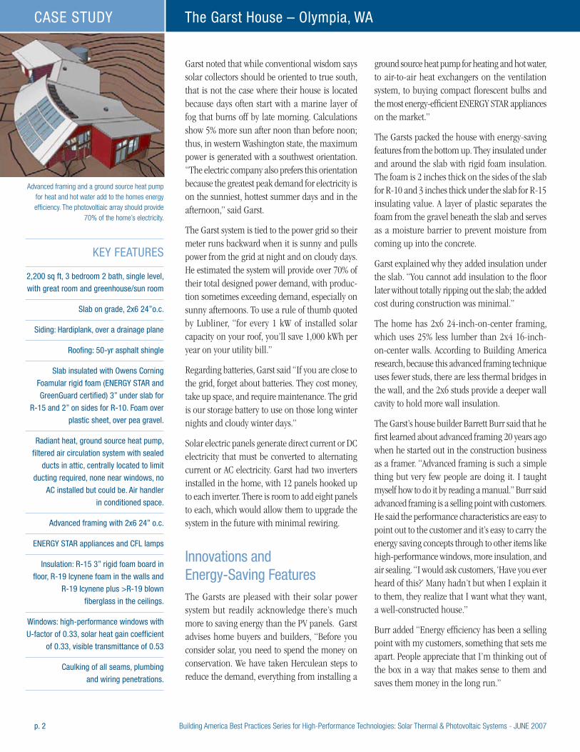
p. 2 Building America Best Practices Series for High-Performance Technologies: Solar Thermal & Photovoltaic Systems - JUNE 2007
The Garst House – Olympia, WACASE STUDY
Garst noted that while conventional wisdom says solar collectors should be oriented to true south, that is not the case where their house is located because days often start with a marine layer of fog that burns off by late morning. Calculations show 5% more sun after noon than before noon; thus, in western Washington state, the maximum power is generated with a southwest orientation. “The electric company also prefers this orientation because the greatest peak demand for electricity is on the sunniest, hottest summer days and in the afternoon,” said Garst.
The Garst system is tied to the power grid so their meter runs backward when it is sunny and pulls power from the grid at night and on cloudy days. He estimated the system will provide over 70% of their total designed power demand, with produc-tion sometimes exceeding demand, especially on sunny afternoons. To use a rule of thumb quoted by Lubliner, “for every 1 kW of installed solar capacity on your roof, you’ll save 1,000 kWh per year on your utility bill.”
Regarding batteries, Garst said “If you are close to the grid, forget about batteries. They cost money, take up space, and require maintenance. The grid is our storage battery to use on those long winter nights and cloudy winter days.”
Solar electric panels generate direct current or DC electricity that must be converted to alternating current or AC electricity. Garst had two inverters installed in the home, with 12 panels hooked up to each inverter. There is room to add eight panels to each, which would allow them to upgrade the system in the future with minimal rewiring.
Innovations and Energy-Saving FeaturesThe Garsts are pleased with their solar power system but readily acknowledge there’s much more to saving energy than the PV panels. Garst advises home buyers and builders, “Before you consider solar, you need to spend the money on conservation. We have taken Herculean steps to reduce the demand, everything from installing a
ground source heat pump for heating and hot water, to air-to-air heat exchangers on the ventilation system, to buying compact florescent bulbs and the most energy-efficient ENERGY STAR appliances on the market.”
The Garsts packed the house with energy-saving features from the bottom up. They insulated under and around the slab with rigid foam insulation. The foam is 2 inches thick on the sides of the slab for R-10 and 3 inches thick under the slab for R-15 insulating value. A layer of plastic separates the foam from the gravel beneath the slab and serves as a moisture barrier to prevent moisture from coming up into the concrete.
Garst explained why they added insulation under the slab. “You cannot add insulation to the floor later without totally ripping out the slab; the added cost during construction was minimal.”
The home has 2x6 24-inch-on-center framing, which uses 25% less lumber than 2x4 16-inch-on-center walls. According to Building America research, because this advanced framing technique uses fewer studs, there are less thermal bridges in the wall, and the 2x6 studs provide a deeper wall cavity to hold more wall insulation.
The Garst’s house builder Barrett Burr said that he first learned about advanced framing 20 years ago when he started out in the construction business as a framer. “Advanced framing is such a simple thing but very few people are doing it. I taught myself how to do it by reading a manual.” Burr said advanced framing is a selling point with customers. He said the performance characteristics are easy to point out to the customer and it’s easy to carry the energy saving concepts through to other items like high-performance windows, more insulation, and air sealing. “I would ask customers, ‘Have you ever heard of this?’ Many hadn’t but when I explain it to them, they realize that I want what they want, a well-constructed house.”
Burr added “Energy efficiency has been a selling point with my customers, something that sets me apart. People appreciate that I’m thinking out of the box in a way that makes sense to them and saves them money in the long run.”
KEY FEATURES
2,200 sq ft, 3 bedroom 2 bath, single level,
with great room and greenhouse/sun room
Slab on grade, 2x6 24”o.c.
Siding: Hardiplank, over a drainage plane
Roofing: 50-yr asphalt shingle
Slab insulated with Owens Corning
Foamular rigid foam (ENERGY STAR and
GreenGuard certified) 3” under slab for
R-15 and 2” on sides for R-10. Foam over
plastic sheet, over pea gravel.
Radiant heat, ground source heat pump,
filtered air circulation system with sealed
ducts in attic, centrally located to limit
ducting required, none near windows, no
AC installed but could be. Air handler
in conditioned space.
Advanced framing with 2x6 24” o.c.
ENERGY STAR appliances and CFL lamps
Insulation: R-15 3” rigid foam board in
floor, R-19 Icynene foam in the walls and
R-19 Icynene plus >R-19 blown
fiberglass in the ceilings.
Windows: high-performance windows with
U-factor of 0.33, solar heat gain coefficient
of 0.33, visible transmittance of 0.53
Caulking of all seams, plumbing
and wiring penetrations.
Advanced framing and a ground source heat pump for heat and hot water add to the homes energy efficiency. The photovoltiaic array should provide
70% of the home’s electricity.
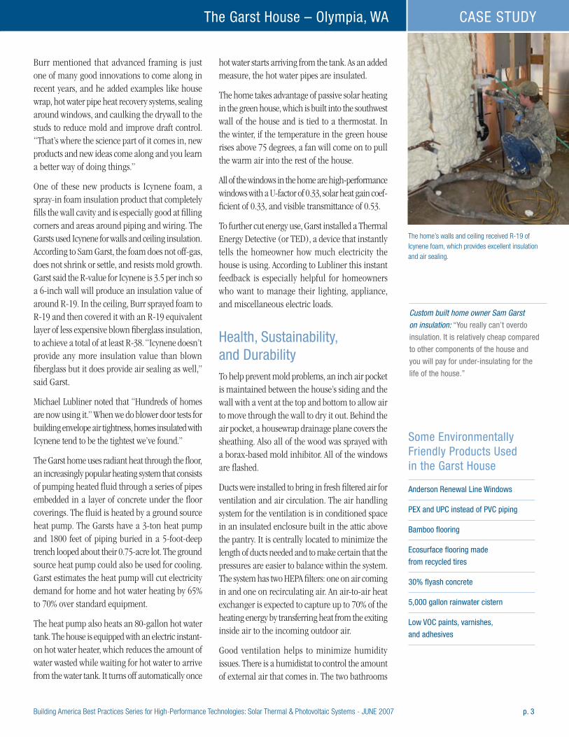
Building America Best Practices Series for High-Performance Technologies: Solar Thermal & Photovoltaic Systems - JUNE 2007 p. 3
The Garst House – Olympia, WA CASE STUDY
Burr mentioned that advanced framing is just one of many good innovations to come along in recent years, and he added examples like house wrap, hot water pipe heat recovery systems, sealing around windows, and caulking the drywall to the studs to reduce mold and improve draft control. “That’s where the science part of it comes in, new products and new ideas come along and you learn a better way of doing things.”
One of these new products is Icynene foam, a spray-in foam insulation product that completely fills the wall cavity and is especially good at filling corners and areas around piping and wiring. The Garsts used Icynene for walls and ceiling insulation. According to Sam Garst, the foam does not off-gas, does not shrink or settle, and resists mold growth. Garst said the R-value for Icynene is 3.5 per inch so a 6-inch wall will produce an insulation value of around R-19. In the ceiling, Burr sprayed foam to R-19 and then covered it with an R-19 equivalent layer of less expensive blown fiberglass insulation, to achieve a total of at least R-38. “Icynene doesn’t provide any more insulation value than blown fiberglass but it does provide air sealing as well,” said Garst.
Michael Lubliner noted that “Hundreds of homes are now using it.” When we do blower door tests for building envelope air tightness, homes insulated with Icynene tend to be the tightest we’ve found.”
The Garst home uses radiant heat through the floor, an increasingly popular heating system that consists of pumping heated fluid through a series of pipes embedded in a layer of concrete under the floor coverings. The fluid is heated by a ground source heat pump. The Garsts have a 3-ton heat pump and 1800 feet of piping buried in a 5-foot-deep trench looped about their 0.75-acre lot. The ground source heat pump could also be used for cooling. Garst estimates the heat pump will cut electricity demand for home and hot water heating by 65% to 70% over standard equipment.
The heat pump also heats an 80-gallon hot water tank. The house is equipped with an electric instant-on hot water heater, which reduces the amount of water wasted while waiting for hot water to arrive from the water tank. It turns off automatically once
hot water starts arriving from the tank. As an added measure, the hot water pipes are insulated.
The home takes advantage of passive solar heating in the green house, which is built into the southwest wall of the house and is tied to a thermostat. In the winter, if the temperature in the green house rises above 75 degrees, a fan will come on to pull the warm air into the rest of the house.
All of the windows in the home are high-performance windows with a U-factor of 0.33, solar heat gain coef-ficient of 0.33, and visible transmittance of 0.53.
To further cut energy use, Garst installed a Thermal Energy Detective (or TED), a device that instantly tells the homeowner how much electricity the house is using. According to Lubliner this instant feedback is especially helpful for homeowners who want to manage their lighting, appliance, and miscellaneous electric loads.
Health, Sustainability, and DurabilityTo help prevent mold problems, an inch air pocket is maintained between the house’s siding and the wall with a vent at the top and bottom to allow air to move through the wall to dry it out. Behind the air pocket, a housewrap drainage plane covers the sheathing. Also all of the wood was sprayed with a borax-based mold inhibitor. All of the windows are flashed.
Ducts were installed to bring in fresh filtered air for ventilation and air circulation. The air handling system for the ventilation is in conditioned space in an insulated enclosure built in the attic above the pantry. It is centrally located to minimize the length of ducts needed and to make certain that the pressures are easier to balance within the system. The system has two HEPA filters: one on air coming in and one on recirculating air. An air-to-air heat exchanger is expected to capture up to 70% of the heating energy by transferring heat from the exiting inside air to the incoming outdoor air.
Good ventilation helps to minimize humidity issues. There is a humidistat to control the amount of external air that comes in. The two bathrooms
The home’s walls and ceiling received R-19 of Icynene foam, which provides excellent insulation and air sealing.
Custom built home owner Sam Garst on insulation: “You really can’t overdo
insulation. It is relatively cheap compared
to other components of the house and
you will pay for under-insulating for the
life of the house.”
Some Environmentally Friendly Products Used in the Garst House
Anderson Renewal Line Windows
PEx and UPC instead of PVC piping
Bamboo flooring
Ecosurface flooring made
from recycled tires
30% flyash concrete
5,000 gallon rainwater cistern
Low VOC paints, varnishes,
and adhesives
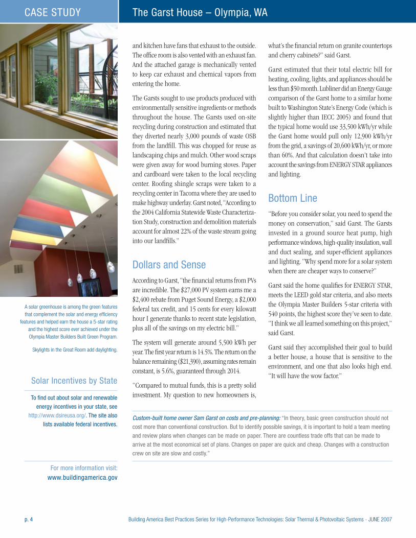
p. 4 Building America Best Practices Series for High-Performance Technologies: Solar Thermal & Photovoltaic Systems - JUNE 2007
The Garst House – Olympia, WACASE STUDY
and kitchen have fans that exhaust to the outside. The office room is also vented with an exhaust fan. And the attached garage is mechanically vented to keep car exhaust and chemical vapors from entering the home.
The Garsts sought to use products produced with environmentally sensitive ingredients or methods throughout the house. The Garsts used on-site recycling during construction and estimated that they diverted nearly 3,000 pounds of waste OSB from the landfill. This was chopped for reuse as landscaping chips and mulch. Other wood scraps were given away for wood burning stoves. Paper and cardboard were taken to the local recycling center. Roofing shingle scraps were taken to a recycling center in Tacoma where they are used to make highway underlay. Garst noted, “According to the 2004 California Statewide Waste Characteriza-tion Study, construction and demolition materials account for almost 22% of the waste stream going into our landfills.”
Dollars and SenseAccording to Garst, “the financial returns from PVs are incredible. The $27,000 PV system earns me a $2,400 rebate from Puget Sound Energy, a $2,000 federal tax credit, and 15 cents for every kilowatt hour I generate thanks to recent state legislation, plus all of the savings on my electric bill.”
The system will generate around 5,500 kWh per year. The first year return is 14.5%. The return on the balance remaining ($21,390), assuming rates remain constant, is 5.6%, guaranteed through 2014.
“Compared to mutual funds, this is a pretty solid investment. My question to new homeowners is,
what’s the financial return on granite countertops and cherry cabinets?” said Garst.
Garst estimated that their total electric bill for heating, cooling, lights, and appliances should be less than $50 month. Lubliner did an Energy Gauge comparison of the Garst home to a similar home built to Washington State’s Energy Code (which is slightly higher than IECC 2005) and found that the typical home would use 33,500 kWh/yr while the Garst home would pull only 12,900 kWh/yr from the grid, a savings of 20,600 kWh/yr, or more than 60%. And that calculation doesn’t take into account the savings from ENERGY STAR appliances and lighting.
Bottom Line“Before you consider solar, you need to spend the money on conservation,” said Garst. The Garsts invested in a ground source heat pump, high performance windows, high-quality insulation, wall and duct sealing, and super-efficient appliances and lighting. “Why spend more for a solar system when there are cheaper ways to conserve?”
Garst said the home qualifies for ENERGY STAR, meets the LEED gold star criteria, and also meets the Olympia Master Builders 5-star criteria with 540 points, the highest score they’ve seen to date. “I think we all learned something on this project,” said Garst.
Garst said they accomplished their goal to build a better house, a house that is sensitive to the environment, and one that also looks high end. “It will have the wow factor.”
A solar greenhouse is among the green features that complement the solar and energy efficiency
features and helped earn the house a 5-star rating and the highest score ever achieved under the Olympia Master Builders Built Green Program.
Skylights in the Great Room add daylighting.
Solar Incentives by State
To find out about solar and renewable
energy incentives in your state, see
http://www.dsireusa.org/. The site also
lists available federal incentives.Custom-built home owner Sam Garst on costs and pre-planning: “In theory, basic green construction should not
cost more than conventional construction. But to identify possible savings, it is important to hold a team meeting
and review plans when changes can be made on paper. There are countless trade offs that can be made to
arrive at the most economical set of plans. Changes on paper are quick and cheap. Changes with a construction
crew on site are slow and costly.”
For more information visit: www.buildingamerica.gov
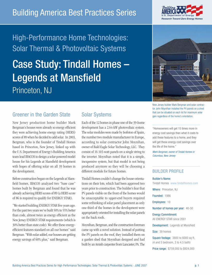
Building America Best Practices Series for High-Performance Technologies: Solar Thermal & Photovoltaic Systems - JUNE 2007 p. 1
High-Performance Home Technologies: Solar Thermal & Photovoltaic Systems
Case Study: Tindall Homes – Legends at Mansfield Princeton, NJ
Building America Best Practices Series
Greener in the Garden StateNew Jersey production home builder Mark Bergman’s houses were already so energy efficient they were achieving home energy rating (HERS) scores of 89 when he decided to add solar. In 2003, Bergman, who is the founder of Tindall Homes based in Princeton, New Jersey, linked up with the U.S. Department of Energy’s Building America team lead IBACOS to design a solar-powered model house for his Legends at Mansfield development with hopes of offering solar on all 39 homes in the development.
Before construction began on the Legends at Mans-field homes, IBACOS analyzed two “base case” homes built by Bergman and found that he was already achieving HERS scores of 89 (a HERS score of 86 is required to qualify for ENERGY STAR).
“We started building ENERGY STAR five years ago. For the past two years we’ve built 50% to 55% better than code, almost twice as energy efficient as the New Jersey ENERGY STAR requirements (which is 30% better than state code). We offer these energy-efficient features standard on all our homes” said Bergman. “With solar added, our houses are getting energy savings of 60% plus,” said Bergman.
Solar SystemsEach of the 12 homes in phase one of the 39-home development has a 2.64-kW photovoltaic system. The solar modules were made by Isofoton of Spain, the number two module manufacturer in Europe, according to solar contractor John Moynihan, owner of Bald Eagle Solar Technology, LLC. They consist of 16 165-watt panels on a single string to the inverter. Moynihan noted that it is a simple, inexpensive system, but that model is not being produced anymore so they will be choosing a different module for future homes.
Tindall Homes couldn’t change the house orienta-tions on their lots, which had been approved two years prior to construction. The builder’s fear that PV panels visible on the front of the homes would be unacceptable to upper-end buyers required some rethinking of solar panel placement as only one-third of the homes in the development were appropriately oriented for installing the solar panels on the back roofs.
Moynihan, Bergman, and the construction foreman came up with a novel solution. Instead of putting the PV panels on the roof, they installed them on a garden shed that Moynihan designed and had built by an Amish carpenter from Lancaster, PA. The
BUILDER PROFILE
Builder’s Name:
Tindall Homes www.tindallhomes.com
Where: Princeton, NJ
Founded: 1986
Employees: 10
Number of homes per year: 40-50
Energy Commitment:
All ENERGY STAR since 2001
Development: Legends at Mansfield
Size: 39 homes
Square footage: 3800 to 6000 sq ft,
(4 and 5 bedroom, 3 to 4.5 bath)
Price range: $759,000 to $924,000
New Jersey builder Mark Bergman and solar contrac-tor John Moynihan installed the PV panels on a shed that can be situated on each lot for maximum solar gain regardless of the home’s orientation.
“Homeowners will get 15 times more in
energy cost savings than what it costs to
add these features to a home, and they
will get these energy cost savings over
the life of the home.” Mark Bergman, owner of Tindall Homes in Columbus, New Jersey
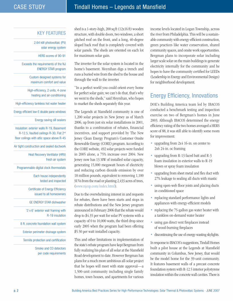
p. 2 Building America Best Practices Series for High-Performance Technologies: Solar Thermal & Photovoltaic Systems - JUNE 2007
Tindall Homes – Legends at MansfieldCASE STUDY
shed is a 1-story-high, 200 sq ft (12x16 ft) wooden structure, with double doors, two windows, a short pitched roof on the front, and a long, 40-degree sloped back roof that is completely covered with solar panels. The sheds are oriented on each lot for maximum solar gain.
The inverter for the solar system is located in the home’s basement. Moynihan digs a trench and runs a buried wire from the shed to the house and through the wall to the inverter.
“In a perfect world you could orient every home for perfect solar gain; we can’t do that, that’s why we went to the sheds,” said Moynihan, who hopes to market the sheds separately this year.
The Legends at Mansfield community is one of 1,200 solar projects in New Jersey as of March 2006, up from just six solar installations in 2001, thanks to a combination of rebates, financial incentives, and support provided by The New Jersey Clean Energy Program’s Customer Onsite Renewable Energy (CORE) program. According to the CORE website, 492 solar projects were funded in 2005 alone, a 75% increase over 2004. New Jersey now has 13 MW of installed solar capacity, generating 15,000 megawatt hours of electricity and reducing carbon dioxide emission by over 18 million pounds, equivalent to removing 1,100 SUVs from the road or planting 2,433 acres of trees, (www.njcep.com/index.html).
Due to the overwhelming interest in and requests for rebates, there have been starts and stops in rebate distributions and the New Jersey program announced in February 2006 that the rebate would drop to $4.35 per watt for solar PV systems with a capacity of 0 to 10,000 watts, the third drop since early 2005 when the program had been offering $5.50 per watt installed capacity.
This and other limitations in implementation of the state’s rebate program have kept Bergman from fully realizing his plan of all solar at the Mansfield Road development to date. However Bergman has plans for a much more ambitious all-solar project that he hopes will meet with state approval—a 1,500-unit community including single family homes, town houses, and apartments for various
income levels located in Logan Township, across the river from Philadelphia. This will be a sustain-able community with energy-efficient construction, green practices like water conservation, shared community spaces, and onsite work opportunities. Bergman plans to incorporate solar including larger scale solar on the main buildings to generate electricity internally for the community and he hopes to have the community certified for LEEDs (Leadership in Energy and Environmental Design) for neighborhood development.
Energy Efficiency, InnovationsDOE’s Building America team led by IBACOS conducted a benchmark testing and inspection exercise on two of Bergman’s homes in June 2003. Although IBACOS determined the energy efficiency rating of the two homes averaged a HERS score of 88, it was still able to identify some room for improvement:
• upgrading from 2x4 16-in. on center to 2x6 24-in. oc framing
• upgrading from R-13 faced batt and R-3 foam insulation in exterior walls to R-19 blown or spray foam insulation
• upgrading from sheet metal and flex duct with 27% leakage to sealing all ducts with mastic
• using open-web floor joists and placing ducts in conditioned space
• replacing standard performance lights and appliances with energy-efficient models
• replacing the 75-gallon gas water heater with a tankless on-demand water heater
• using gas direct vent fireplaces instead of wood-burning fireplaces
• discontinuing the use of energy-wasting skylights.
In response to IBACOS’s suggestions, Tindall Homes built a pilot house at the Legends at Mansfield community in Columbus, New Jersey, that would be the model home for the 39-unit community. It features basement walls of a precast concrete foundation system with R-12.5 interior polystyrene insulation within the concrete wall cavities. There is
KEY FEATURES
2.64 kW photovoltaic (PV)
solar energy system
HERS scores of 90-91
Exceeds the requirements of the NJ
ENERGY STAR program
Custom designed systems for
maximum comfort and value
High-efficiency, 2 units, 4-zone
heating and air-conditioning
High-efficiency tankless hot water heater
Energy efficient low-E double pane windows
Energy saving sill sealers
Insulation: exterior walls R-19, Basement
R-12.5, Vaulted ceilings R-30, Flat 2nd
floor ceilings with attic space above R-45
Air tight construction and sealed ductwork
Heat Recovery Ventilator (HRV)
fresh air system
Programmable digital clock thermostats
Each house independently
tested and inspected
Certificate of Energy Efficiency
issued to all homeowners
GE ENERGY STAR dishwasher
‘2 x 6’ exterior wall framing with
R-19 insulation
8 ft. concrete foundation wall system
Exterior perimeter drainage system
Termite protection and certification
Smoke and CO detectors
per code requirements

Building America Best Practices Series for High-Performance Technologies: Solar Thermal & Photovoltaic Systems - JUNE 2007 p. 3
Tindall Homes – Legends at Mansfield CASE STUDY
a 3-inch-thick spray foam urethane insulation within the 2x6 exterior wall cavities making it a R-19 wall. The attic uses a combination of blown-in cellulose plus fiberglass batt insulation to achieve R-45. Greater sealing of penetrations together with the use of spray foam in the wall cavities helps achieve a continuous air barrier and an air-change rate of 0.10 ACH. A drainage plane layer is used over insulating foam sheathing and is correctly integrated with flashing, which is properly applied around windows and door areas to promote shedding of water.
The house sports two optimally sized high-efficiency (92% AFUE) direct vent furnaces and 14 SEER condensing units. A direct vent gas tankless water heater provides hot water. The entire air distribution system is located in conditioned space with ducts traveling through an open web joist system. A central, fully ducted return system serves each floor with transfer grilles in bedrooms walls, allowing for the transfer of air from bedrooms to the return system. The total air distribution system air leakage target is 10% of system airflow, with no air leakage to the outside. A heat recovery ventilator provides balanced mechanical ventilation.
IBACOS ran EnergyGauge USA software version 2.1 to calculate end-use and determined that the pilot home built to the design specifications (not including the contribution of the photovoltaic system) would save 46% with respect to the Building America benchmark house and 32% with respect to Bergman’s standard home for total end-use source energy. These savings rise to 54% and 43% when the contribution of the photovoltaic system is included. The pilot home and other PV homes built in the Legends at Mansfield community are achieving HERS scores of 90 and 91.
“The sales office is actively marketing the energy efficiency of Bergman’s homes; they state it in the first five sentences to the potential buyer,” said Moynihan, who added that he feels it sets Bergman apart as a home builder.
“Mark is a true pioneer, he has taken some risks. I don’t know of any other builder in NJ who has committed to all solar on a market-rate residen-tial development. He really cares about energy efficiency. Mark is doing it because it’s the right thing to do,” said Moynihan.
Moynihan went on to share a story about the builder. “Mark got in an argument with one of his homeowners. The homeowner wanted 80 incandescent can lights in his new house. Mark said ‘No, I can’t do that because it blows my energy efficiency rating for the house, and it’s the wrong thing to do. But we’ll give you as many fluorescent fixtures as you want.’ The guy was ready to walk away from his contract but Mark won him over. The trick is getting people to want it,” said Moynihan.
Dollars and Sense“Homeowners will get 15 times more in energy cost savings than what it costs to add these features to a home, and they will get these energy cost savings over the life of the home,” said Bergman.
IBACOS estimated that cost savings (based on an average electricity rate of $0.101/kWh and a gas rate of $0.8798/therm) without including the PV were 32% or $1,122; with PV included cost savings were 43% or $1,511.
(left) Homeowners love the garden sheds; they also love the 50% to 60% energy savings they are getting from Bergman’s energy-efficient construction and the solar panels installed on the shed’s back roof.
(middle) It’s easy and safe to install PV panels for the 2.64-kW photovoltaic system on the low 200-sq.ft structures.
(right) The Building America team lead by IBACOS worked with Tindall Homes to build New Jersey’s first solar home development priced at market rates.
“We all want to make money but at some
point as a society we have to evaluate
what we are doing. Our homes cut energy
use by 50%-55% over houses built to
the state code. Over the lifetime of the
house, our (Tindall) homes will save more
in energy costs than the purchase price
of the house. If we all did this, we could
make a big difference.” Mark Bergman, owner of Tindall Homes in Columbus, New Jersey

p. 4 Building America Best Practices Series for High-Performance Technologies: Solar Thermal & Photovoltaic Systems - JUNE 2007
Tindall Homes – Legends at MansfieldCASE STUDY
The Bottom Line“We all want to make money but at some point as a society we have to evaluate what we are doing. Our homes cut energy use by 50% to 55% over houses built to the state code. Over the lifetime of the house, our (Tindall) homes will save more in energy costs than the purchase price of the house. If we all did this, we could make a big difference,” said Bergman.
According to Moynihan, they are already making a big difference for Tindall home owners. “A homeowner called me up one Friday night. He
and his wife had just bought one of our homes and he called me to tell that he had just got his electric bill and it was only $48 for the month. He said ‘this house is twice as big as my last house and my electric bill is half as much.’ A young guy like that should have something better to do on a Friday night then call his builder about his electric bill, but he was that excited about it,” said Moynihan.
“At the end of the day people need a place to live. For the public good, it would be nice if the place they live in doesn’t waste energy or pollute the environ-ment and is sustainable,” said Moynihan.
Wiring for the photovoltaic system runs underground from the sheds to the houses.
Thermal Envelope ImprovementsAdded 1-time upfront cost
Annual savings to homeowner
Simple Payback
Superior Walls precast concrete basement
walls with exterior rigid foam and R-13
batts in wall cavities
$0 $209 33.5 yrs
Taped R-3 rigid foam sheathing on exterior walls $2000
R-18 spray foam urethane insulation in wall
cavities instead of fiberglass batt
$5000
R-30 batt plus R-15 loose cellulose in ceiling $0
Drainage plane of plastic house wrap over foam
sheathing and better window and door flashing
$0
Draftstopping at bathtubs, chases, behind the
fireplace, and knee walls of exercise room
and sealing of all penetrations
$600 $75 8 yrs
Floor joists switched from engineered
wood to open web floor joists for ducts in
conditioned space
$3000 $395 11.9 yrs
Engineered HVAC with 14 SEER, 92% AFUE
and variable speed blower on two systems
$1000
Heat recovery ventilator $700
Tankless, gas-fired water heater $500 $86 5.8 yrs
Energy-efficient lighting and appliances $350 $243 1.4 yrs
PV Generation $5,000
(after rebates)
$389 12.8 yrs
“We started building ENERGY STAR five
years ago. For the past two years we’ve
built 50% to 55% better than code,
almost twice as energy efficient as the
New Jersey ENERGY STAR requirements
(which is 30% better than state code).
We offer these energy-efficient features
standard on all our homes. With solar
added, our houses are getting energy
savings of 60% plus,” said Bergman. New Jersey builder Mark Bergman
Estimated costs, savings, and paybacks for efficiency improvements recommended by IBACOS for pilot house over builders’ standard practice (from a June 2004 report by IBACOS)
For more information visit: www.buildingamerica.gov
Building America Best Practices Series for High-Performance Technologies: Solar Thermal & Photovoltaic Systems - JUNE 2007 APPENDIX I / p.1
High-Performance Home Technologies: Solar Thermal & Photovoltaic Systems
Appendix I:PV System Installation Checklist Courtesy of ConSol
Building America Best Practices Series
ConSol leads the Building Industry Research Alliance, one of seven Building America consortia. For a complete listing of consortia and contact information see the back cover.
Bringing you a prosperous future where energy is clean, abundant, reliable, and affordable
A Strong Energy Portfolio for a Strong AmericaEnergy efficiency and clean, renewable energy will mean a stronger economy, a cleaner environment, and greater energy independence for America. Working with a wide array of state, community, industry, and university partners, the U.S. Department of Energy’s Office of Energy Efficiency and Renewable Energy invests in a diverse portfolio of energy technologies.
Research and Development of Buildings
Our nation’s buildings consume more energy than any other sector of the U.S. economy, including transportation and industry. Fortunately, the opportun-ities to reduce building energy use— and the associated environmental impacts—are significant.
DOE’s Building Technologies Program works to improve the energy efficiency of our nation’s buildings through inno-vative new technologies and better building practices. The program focuses on two key areas:
• Emerging Technologies Research and development of the next generation of energy-efficient components, materials, and
equipment
• Technology Integration Integration of new technologies with innovative building methods to optimize building performance and savings
For more information contact:EERE Information Center1-877-EERE-INF (1-877-337-3463)www.eere.energy.gov
An electronic copy of this publication is available on the Building America Web site at www.buildingamerica.gov
U.S. Department of Energy
Energy Efficiencyand Renewable Energy
Building America Program George S. James • New Construction • 202-586-9472 • fax: 202-586-8134 • e-mail: [email protected] Terry Logee • Existing Homes • 202-586-1689 • fax: 202-586-4617 • e-mail: [email protected] Lew Pratsch • Integrated Onsite Power • 202-586-1512 • fax: 202-586-8185 • e-mail: [email protected] Building America Program • Office of Building Technologies, EE-2J • U.S. Department of Energy • 1000 Independence Avenue, S.W. • Washington, D.C. 20585-0121 • www.buildingamerica.gov
Building Industry Research Alliance (BIRA) Robert Hammon • ConSol • 7407 Tam O’Shanter Drive #200 • Stockton, CA 95210-3370 • 209-473-5000 • fax: 209-474-0817 • e-mail: [email protected] • www.bira.ws
Building Science Consortium (BSC) Betsy Pettit • Building Science Consortium (BSC) • 70 Main Street • Westford, MA 01886 • 978-589-5100 • fax: 978-589-5103 • e-mail: [email protected] • www.buildingscience.com
Consortium for Advanced Residential Buildings (CARB) Steven Winter • Steven Winter Associates, Inc. • 50 Washington Street • Norwalk, CT 06854 • 203-857-0200 • fax: 203-852-0741 • e-mail: [email protected] • www.carb-swa.com
Davis Energy Group David Springer • Davis Energy Group • 123 C Street • Davis, CA 95616 • 530-753-1100 • fax: 530-753-4125 • e-mail: [email protected] • [email protected] • www.davisenergy.com/index.html
IBACOS Consortium Brad Oberg • IBACOS Consortium • 2214 Liberty Avenue • Pittsburgh, PA 15222 • 412-765-3664 • fax: 412-765-3738 • e-mail: [email protected] • www.ibacos.com
Industrialized Housing Partnership (IHP)
Subrato Chandra • Florida Solar Energy Center • 1679 Clearlake Road • Cocoa, FL 32922 • 321-638-1412 • fax: 321-638-1439 • e-mail: [email protected] • www.baihp.org
National Association of Home Builders (NAHB) Research Center Tom Kenney • National Association of Home Builders (NAHB) Research Center • 400 Prince George’s Boulevard • Upper Marlboro, MD 20774 • 301-430-6246 • fax: 301-430-6180 • toll-free: 800-638-8556 • www.nahbrc.org/
National Renewable Energy Laboratory Ren Anderson • 1617 Cole Boulevard, MS-2722 • Golden, CO 80401 • 303-384-7433 • fax: 303-384-7540 • e-mail: [email protected] • www.nrel.gov
Tim Merrigan • 1617 Cole Boulevard, MS-2722 • Golden, CO 80401 • 303-384-7349 • fax: 303-384-7540 • e-mail: [email protected] • www.nrel.gov
Oak Ridge National Laboratory Pat M. Love • P.O. Box 2008 • One Bethel Valley Road • Oak Ridge, TN 37831 • 865-574-4346 • fax: 865-574-9331 • e-mail: [email protected] • www.ornl.gov
Pacific Northwest National Laboratory Michael Baechler • 620 SW 5th, Suite 810 • Portland, OR 97204 • 503-417-7553 • fax: 503-417-2175 • e-mail: [email protected] • www.pnl.gov
Produced for the U.S. Department of Energy (DOE) by the National Renewable Energy Laboratory, a DOE national laboratory.
June 2007 • NREL/TP-550-41085 Printed with a renewable-source ink on paper containing at least 50% wastepaper, including 20% postconsumer waste.
Visit our Web sites at:
www.buildingamerica.gov www.pathnet.org www.energystar.gov
Research Toward Zero Energy Homes
F1147-E(12/2004)
REPORT DOCUMENTATION PAGE Form Approved OMB No. 0704-0188
The public reporting burden for this collection of information is estimated to average 1 hour per response, including the time for reviewing instructions, searching existing data sources, gathering and maintaining the data needed, and completing and reviewing the collection of information. Send comments regarding this burden estimate or any other aspect of this collection of information, including suggestions for reducing the burden, to Department of Defense, Executive Services and Communications Directorate (0704-0188). Respondents should be aware that notwithstanding any other provision of law, no person shall be subject to any penalty for failing to comply with a collection of information if it does not display a currently valid OMB control number. PLEASE DO NOT RETURN YOUR FORM TO THE ABOVE ORGANIZATION.1. REPORT DATE (DD-MM-YYYY)
June 2007 2. REPORT TYPE
Technical Report 3. DATES COVERED (From - To)
4. TITLE AND SUBTITLE
Building America Best Practices Series High-Performance Home Technologies: Solar Thermal & Photovoltaic Systems
5a. CONTRACT NUMBER DE-AC36-99-GO10337
5b. GRANT NUMBER
5c. PROGRAM ELEMENT NUMBER
6. AUTHOR(S) M. Baechler and P. Love
5d. PROJECT NUMBER NREL/TP-550-41085
5e. TASK NUMBER BET78004
5f. WORK UNIT NUMBER
7. PERFORMING ORGANIZATION NAME(S) AND ADDRESS(ES)Pacific Northwest National Laboratory 902 Battelle Boulevard Richland, WA And Oak Ridge National Laboratory 1 Bethel Valley Road Oak Ridge, TN 37831
8. PERFORMING ORGANIZATION REPORT NUMBER PNNL-16382
9. SPONSORING/MONITORING AGENCY NAME(S) AND ADDRESS(ES)National Renewable Energy Laboratory 1617 Cole Blvd. Golden, CO 80401-3393
10. SPONSOR/MONITOR'S ACRONYM(S)NREL
11. SPONSORING/MONITORING AGENCY REPORT NUMBER NREL/TP-550-41085
12. DISTRIBUTION AVAILABILITY STATEMENT National Technical Information Service U.S. Department of Commerce 5285 Port Royal Road Springfield, VA 22161
13. SUPPLEMENTARY NOTES
14. ABSTRACT (Maximum 200 Words) This document is the sixth volume of the Building America Best Practices Series. It presents information that is useful throughout the United States for enhancing the energy efficiency practices in the specific climate zones that are presented in the first five Best Practices volumes. It provides an introduction to current photovoltaic and solar thermal building practices. Information about window selection and shading is included.
15. SUBJECT TERMS building america; best practices; photovoltaic; solar thermal; climate zones
16. SECURITY CLASSIFICATION OF: 17. LIMITATION OF ABSTRACT
UL
18. NUMBER OF PAGES
19a. NAME OF RESPONSIBLE PERSON a. REPORT
Unclassified b. ABSTRACT Unclassified
c. THIS PAGE Unclassified 19b. TELEPHONE NUMBER (Include area code)
Standard Form 298 (Rev. 8/98) Prescribed by ANSI Std. Z39.18