high frequency spindle z62-k360.12 s4a manual · 2019-07-25 · the high frequency spindle (hf...
TRANSCRIPT
Manual
Z62-K360.12 S4A
High Frequency SpindlePneumatic taper change
Item no. 10403103, Revision 122 ( 36 )
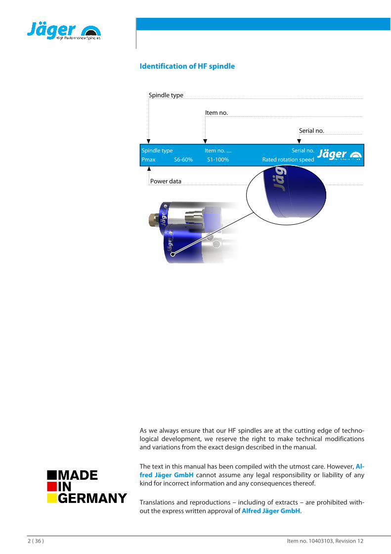
Identification of HF spindle
Spindle type
Pmax S6-60%
Item no. .... Serial no.
Rated rotation speed
Serial no.
Item no.
Power data
Spindle type
S1-100%
As we always ensure that our HF spindles are at the cutting edge of techno-logical development, we reserve the right to make technical modificationsand variations from the exact design described in the manual.
The text in this manual has been compiled with the utmost care. However, Al-fred Jäger GmbH cannot assume any legal responsibility or liability of anykind for incorrect information and any consequences thereof.
Translations and reproductions – including of extracts – are prohibited with-out the express written approval of Alfred Jäger GmbH.
Item no. 10403103, Revision 12 3 ( 36 )
Contents:Translation of the original manual
1 Preliminary information 4
1.1 Purpose of the manual....................................................... 4
1.2 Explanation of symbols used........................................... 4
2 Transport and packaging 5
2.1 Scope of supply of HF spindle......................................... 5
2.1.1 Service set.................................................................. 5
2.1.2 Optional accessories.............................................. 5
2.1.3 Documentation supplied..................................... 6
2.2 Packaging of HF spindle.................................................... 6
3 Designated use 6
3.1 Permissible types of machining...................................... 6
3.2 Permissible materials.......................................................... 6
4 Safety instructions 7
4.1 Safe working .......................................................................... 8
4.2 Shutdown of HF spindle.................................................... 9
4.3 Installation and maintenance.......................................... 9
4.4 Modification and repair ..................................................... 9
4.5 Improper operation ............................................................ 9
5 Technical description 10
5.1 Connections of HF spindle ............................................. 10
5.2 Electrical connection ........................................................ 10
5.3 Cooling .................................................................................. 11
5.4 Sealing air ............................................................................. 11
5.5 Taper cleaning .................................................................... 11
5.6 Pneumatic tool change.................................................... 11
6 Technical Specifications 12
6.1 Dimensions .......................................................................... 13
6.2 Technical data sheet (KL4001 , AC-Motor)................ 14
6.2.1 Performance Diagram........................................ 15
6.3 Wiring diagram ................................................................... 16
6.4 Motor protection PTC 160°C.......................................... 17
6.5 Speed sensor (digital differential magneto resistor).................................................................................................. 17
6.6 ESD protection.................................................................... 18
6.7 Air-borne noise emissions .............................................. 18
7 Operating location 19
8 Installation 20
8.1 Installing the HF spindle.................................................. 20
8.2 Diameter of media supply line...................................... 21
8.3 Cooling water ....................................................................... 21
8.3.1 Quality of cooling water..................................... 21
8.3.2 Setting the cooling............................................... 21
8.4 Compressed air .................................................................... 22
8.4.1 Air purity classes (ISO 8573-1).......................... 22
8.4.2 Setting the sealing air ......................................... 22
8.4.3 Setting values......................................................... 23
9 Commissioning 23
9.1 Running-in schedule.......................................................... 23
9.2 Daily start-up ........................................................................ 24
9.3 Shutdown signal ................................................................. 24
9.4 Commissioning after storage ......................................... 24
10 Tool change 25
10.1 pneumatic taper change.................................................. 25
10.1.1 Changing the tool ................................................ 26
10.2 Tool changing station (optional accessory) .............. 27
10.2.1 pneumatic taper change ................................... 27
10.2.2 Installing the changing station........................ 27
10.2.3 Maintenance........................................................... 27
11 Tools for high speed cutting 28
12 Maintenance 29
12.1 Ball bearings ......................................................................... 29
12.2 Daily cleaning....................................................................... 29
12.2.1 Before commencing work ................................. 29
12.2.2 With every tool change ...................................... 30
12.3 In the case of storage......................................................... 30
12.4 Monthly maintenance....................................................... 30
12.5 Long periods of storage ................................................... 30
12.6 Maximum storage time..................................................... 30
13 Dismantling 31
13.1 Disposal and environmental protection .................... 31
14 Service and repairs 31
14.1 Service partners................................................................... 31
14.2 Malfunctions ......................................................................... 32
15 Warranty 34
16 Declaration of Incorporation 35
Preliminary information
Item no. 10403103, Revision 124 ( 36 )
1 Preliminary informationThe high frequency spindle (HF spindle) is a high quality precision tool forhigh speed machining.
1.1 Purpose of the manualThe manual is an important component of the HF spindle.
Ü Store the manual carefully.
Ü Make the manual available to all persons who work with the HF spindle.
Ü Read the documentation supplied in full.
Ü Before carrying out any work, read the corresponding section of the man-ual carefully again.
1.2 Explanation of symbols usedTo enable quick classification of information, this manual uses visual aids inthe form of symbols and text markings.
Notes are marked with a signal word and a colored box:
DANGER
Dangerous situation!
Results in serious injury or death.
u Measure to avert the danger.
WARNING
Dangerous situation!
May result in serious injury or death.
u Measure to avert the danger.
CAUTION
Dangerous situation!
May result in minor to moderate injury.
u Measure to avert the danger.
Note
May result in material damage. This warning symbol is not a warning for per-sonal injury.
Tip
Tips indicate useful information for users.
Transport and packaging
Item no. 10403103, Revision 12 5 ( 36 )
2 Transport and packagingAvoid strong vibrations or impacts during transportation, as these could dam-age the ball bearings of the HF spindle.
Ü Any damage reduces the accuracy of the HF spindle.
Ü Any damage restricts the functionality of the HF spindle.
Ü Any damage shortens the service life of the HF spindle.
2.1 Scope of supply of HF spindleThe following parts are supplied with the HF spindle:
q High Frequency Spindle
q Tool taper
q Service set
q C-wrench
q Transport packaging
Ü Check the high frequency spindle for completeness upon delivery.
2.1.1 Service setq Felt cleaning taper
q Collet grease
2.1.2 Optional accessoriesAvailable on request:
q Spindle holder
q Frequency converter
q Chiller
q Collet
q Further accessories on request.
Only approved accessories have been tested for operational safety and func-tionality.
Ü Do not use any other accessories – this may invalidate any warranty claimsand compensation claims for damages.
Ü If the spindle holder is to be produced in-house, it is essential to contactAlfred Jäger GmbH before starting production to request the tolerancesand production plan for the spindle holder.
Designated use
Item no. 10403103, Revision 126 ( 36 )
2.1.3 Documentation suppliedThe documents listed below are supplied with the HF spindle:
q Manual
q The declaration of incorporation is part of the manual.
q Inspection protocol
Ü Check that the documentation supplied is complete when the spindle isdelivered. If necessary, request a new copy.
2.2 Packaging of HF spindleAll transport packaging materials can be recycled in appropriate disposal facil-ities.
3 Designated useThe HF spindle is an “incomplete machine” in accordance with the MachineryDirective and cannot perform any function independently. The HF spindle canonly be operated in conjunction with a machine tool and a frequency con-verter.
3.1 Permissible types of machiningThe HF spindle has been developed only for the following types of machining.
q Cutting
q Drilling
q Engraving
q Grinding
Ü Contact Alfred Jäger GmbH if other types of machining are required.
3.2 Permissible materialsThe HF spindle has been developed only for the following materials.
q Metals (such as alloys, cast metals etc.)
q Sintered materials
q Plastics
q Wood
q Graphite
q Stone (marble, etc.)
q Paper and cardboard
q Circuit boards
q Glass and ceramic
Ü Contact Alfred Jäger GmbH if other materials are to be machined.
Safety instructions
Item no. 10403103, Revision 12 7 ( 36 )
4 Safety instructionsThe high frequency spindle is a state of the art product and is safe to operate.
However, the HF spindle may pose a risk in the following cases:
q If it is installed by untrained personnel.
q If it is used incorrectly.
q If it is not used in accordance with its intended use.
The high frequency spindle may only be installed, commissioned, and main-tained by specialist personnel.
Definition: Specialist personnel are persons who are familiar with the assem-bly, installation, commissioning, and operation of the product and have therelevant qualifications for their area of activity. The operator must closely con-trol the responsibility, training, and monitoring of these personnel.
DANGER: Due to explosion.
HF spindles are not approved for use in areas at risk of explosion. Use in suchareas may result in explosions.
u Do not use the HF spindle in potentially explosive atmospheres.
DANGER: Due to flying parts.
The HF spindle operates at high speeds and may therefore be flung away bythese.
u Operate the HF spindle only if it is installed in the machine or system in afixed manner.
Note: Adhere to the limit values.
u Observe the limit values specified in the technical data.
Note: Take account of the machine.
u Observe the manual of the machine in which the HF spindle is installed.
u Observe all safety instructions specified by the machine manufacturer.
u Ensure that the machine does not cause any hazards (e.g. uncontrolledmovements). Do not install the HF spindle in the machine until this hasbeen done.
Note. Do not damage the HF spindle.
u Any damage reduces the accuracy of the HF spindle.
u Any damage restricts the functionality of the HF spindle.
u Any damage shortens the service life of the HF spindle.
Safety instructions
Item no. 10403103, Revision 128 ( 36 )
4.1 Safe workingObserve all safety instructions set out in the manual, the applicable nationalaccident prevention regulations, and the valid company work, operation, andsafety guidelines.
DANGER: Due to flying parts.
Tools that are not clamped correctly will be flung away by the centrifugalforces that occur during machining.
u Use the full clamping depth of the collet.
u Clamp the tool securely.
DANGER: Due to flying parts.
If the wrong rotational direction is used, the clamping system releases andthe tool is flung away.
u It is essential to adhere to the rotational direction of the HF spindle.
WARNING: Risk of injury due to flying parts.
The HF spindle operates at high speeds which may cause chips to fly outwith great force.
u Never remove the protective devices of the machine or system.
u Always wear protective goggles during work.
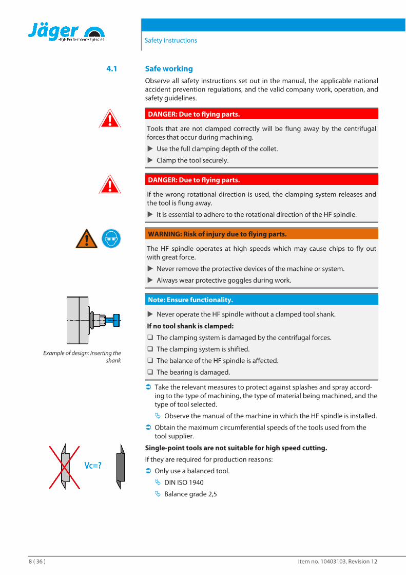
Example of design: Inserting theshank
Note: Ensure functionality.
u Never operate the HF spindle without a clamped tool shank.
If no tool shank is clamped:
q The clamping system is damaged by the centrifugal forces.
q The clamping system is shifted.
q The balance of the HF spindle is affected.
q The bearing is damaged.
Ü Take the relevant measures to protect against splashes and spray accord-ing to the type of machining, the type of material being machined, and thetype of tool selected.
Ä Observe the manual of the machine in which the HF spindle is installed.
Ü Obtain the maximum circumferential speeds of the tools used from thetool supplier.
Single-point tools are not suitable for high speed cutting.
If they are required for production reasons:
Ü Only use a balanced tool.
Ä DIN ISO 1940
Ä Balance grade 2,5
Safety instructions
Item no. 10403103, Revision 12 9 ( 36 )
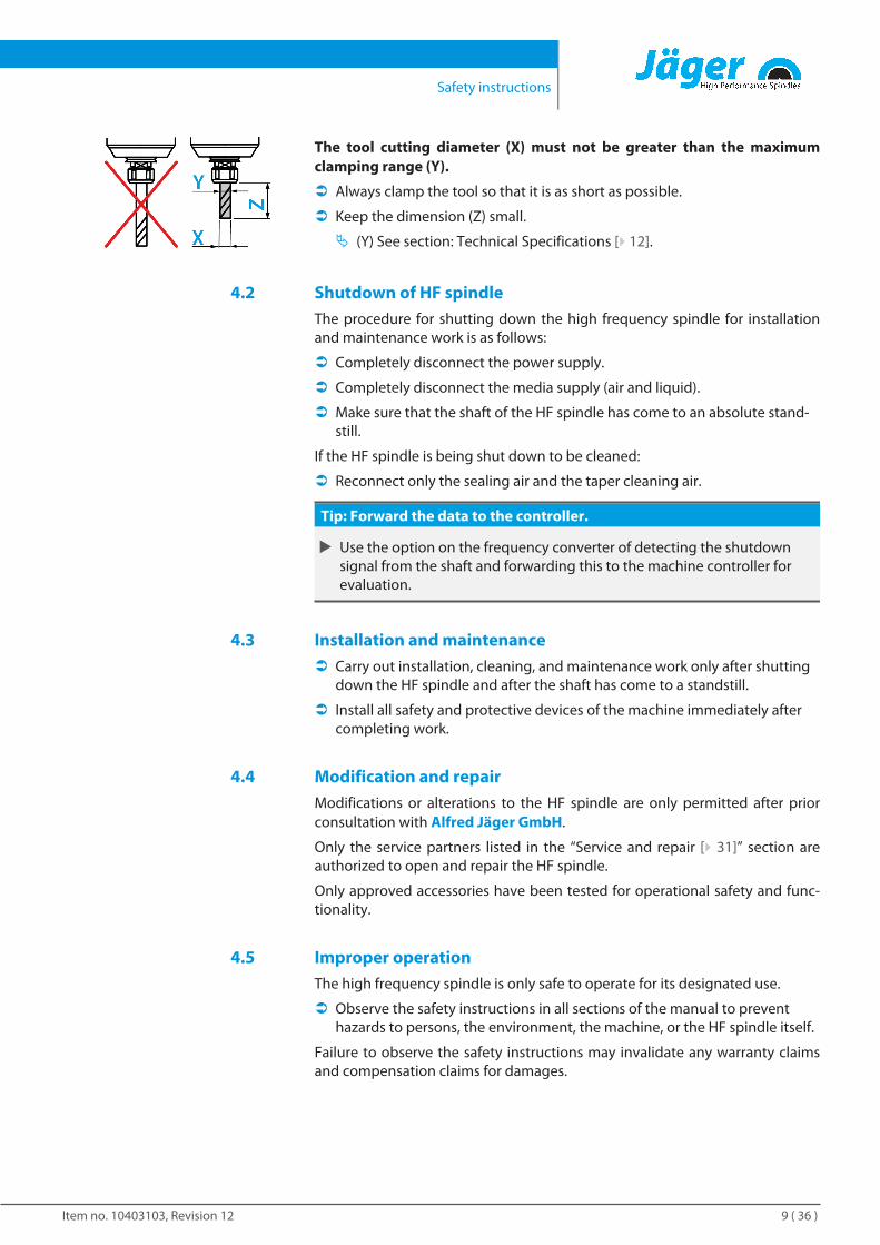
The tool cutting diameter (X) must not be greater than the maximumclamping range (Y).
Ü Always clamp the tool so that it is as short as possible.
Ü Keep the dimension (Z) small.
Ä (Y) See section: Technical Specifications [} 12].
4.2 Shutdown of HF spindleThe procedure for shutting down the high frequency spindle for installationand maintenance work is as follows:
Ü Completely disconnect the power supply.
Ü Completely disconnect the media supply (air and liquid).
Ü Make sure that the shaft of the HF spindle has come to an absolute stand-still.
If the HF spindle is being shut down to be cleaned:
Ü Reconnect only the sealing air and the taper cleaning air.
Tip: Forward the data to the controller.
u Use the option on the frequency converter of detecting the shutdownsignal from the shaft and forwarding this to the machine controller forevaluation.
4.3 Installation and maintenanceÜ Carry out installation, cleaning, and maintenance work only after shutting
down the HF spindle and after the shaft has come to a standstill.
Ü Install all safety and protective devices of the machine immediately aftercompleting work.
4.4 Modification and repairModifications or alterations to the HF spindle are only permitted after priorconsultation with Alfred Jäger GmbH.
Only the service partners listed in the “Service and repair [} 31]” section areauthorized to open and repair the HF spindle.
Only approved accessories have been tested for operational safety and func-tionality.
4.5 Improper operationThe high frequency spindle is only safe to operate for its designated use.
Ü Observe the safety instructions in all sections of the manual to preventhazards to persons, the environment, the machine, or the HF spindle itself.
Failure to observe the safety instructions may invalidate any warranty claimsand compensation claims for damages.
Technical description
Item no. 10403103, Revision 1210 ( 36 )
5 Technical description
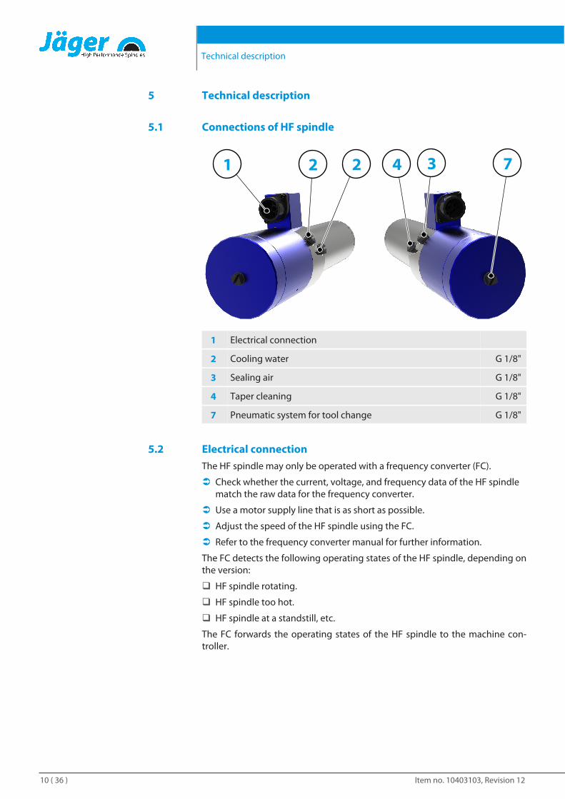
5.1 Connections of HF spindle
21 42 73
1 Electrical connection
2 Cooling water G 1/8"
3 Sealing air G 1/8"
4 Taper cleaning G 1/8"
7 Pneumatic system for tool change G 1/8"
5.2 Electrical connectionThe HF spindle may only be operated with a frequency converter (FC).
Ü Check whether the current, voltage, and frequency data of the HF spindlematch the raw data for the frequency converter.
Ü Use a motor supply line that is as short as possible.
Ü Adjust the speed of the HF spindle using the FC.
Ü Refer to the frequency converter manual for further information.
The FC detects the following operating states of the HF spindle, depending onthe version:
q HF spindle rotating.
q HF spindle too hot.
q HF spindle at a standstill, etc.
The FC forwards the operating states of the HF spindle to the machine con-troller.
Technical description
Item no. 10403103, Revision 12 11 ( 36 )
5.3 CoolingLiquid cooling keeps the HF spindle at a constant temperature during opera-tion.
Note: Extension of the service life through heat dissipation.
Heat is produced during operation of the HF spindle. The temperature of theHF spindle should not exceed + 45° C as this shortens the service life of thebearing.
u Check the temperature of the HF spindle on the housing.
5.4 Sealing airFor guidelines on air quality, see"Air purity classes (ISO 8573-1)[} 22]" section.
The sealing air prevents foreign bodies such as chips and liquids (e.g. emul-sions) from entering the HF spindle.
Ü Check that air escapes at the front between the housing and the rotatingparts of the HF spindle.
5.5 Taper cleaningFor guidelines on air quality, see"Air purity classes (ISO 8573-1)[} 22]" section.
Taper cleaning prevents chips and liquids from entering the shaft during atool change and causing contamination and damage to the inner taper andthe clamping system.
5.6 Pneumatic tool changeFor guidelines on air quality, see"Air purity classes (ISO 8573-1)[} 22]" section.
The tool change or tool taper change is performed pneumatically.
During this, a mechanism is operated inside the HF spindle which clamps, re-leases, or ejects the tool taper or collet.
Technical Specifications
Item no. 10403103, Revision 1212 ( 36 )
6 Technical Specifications
Bearings Hybrid ball bearing (pcs) 2
Lifetime lubricated maintenance free
Power values
Liquid cooledPmax / 5 s S6-60% S1-100%
Rated power 2,5 1,4 1,2 [kW]
Voltage 249 211 206 [V]
Current 11 6,5 6 [A]
Motor dataMotor technology 3-phase asynchronous drive
(no brushes or sensors)
Frequency 1.000 Hz
Motor poles (pairs) 1
Rated rotation speed 60.000 rpm
Acceleration/braking value
Per second
10.000 rpm
(other values by consultation)
CharacteristicsSpeed sensor Differential magneto resistor
Number of signals = 6
Motor protection PTC 160°C
Housing Stainless steel
Housing diameter 61,9 mm
Cooling Liquid cooled
Ambient temperature + 10°C … + 45°C
Sealing air
Protection category
(sealing air turned on)IP54
Taper cleaning
ESD protection
Tool change Pneumatic taper change
Tool Holder WK 16
Collet typeD6
Optional accessories
Clamping range up to 6 mm (1/4" )
Clockwise
Coupler plug 9-pin plastic
Weight ~ 3,8 kg
Technical Specifications
Item no. 10403103, Revision 12 13 ( 36 )
Inner taper run out < 1 µ
Axial run-out < 1 µ
6.1 Dimensions
(*) = Clamping range
Technical Specifications
Item no. 10403103, Revision 1214 ( 36 )
6.2 Technical data sheet (KL4001 , AC-Motor)The power values (S1, S6, S2) arevalid for sinusoidal currents andvoltages.
The power values of the HF spin-dle are dependent on the fre-quency converter used and mayvary from the indicated values.
Motor type 4/7-2
Rated power 1,2 kW
Rated rotation speed 60.000 rpm
Cooling Liquid cooled
Motor protection PTC 160°C
Winding resistance 2,25 Ω
Measured values: S1-100%
Rated rotation speed 10.000 15.000 20.000 25.000 30.000 40.000 50.000 60.000 rpm
Speed 8.793 13.459 18.304 22.856 27.860 37.684 47.509 56.761 rpm
Frequency 167 250 333 417 500 667 833 1.000 Hz
Rated power 0,192 0,289 0,419 0,524 0,633 0,853 1,044 1,249 kW
Torque 0,21 0,21 0,22 0,22 0,22 0,22 0,21 0,21 Nm
Voltage 55 74 91 105 121 152 183 206 V
Current 6 6 6 6 6 6 6 6 A
Cos φ 0,78 0,75 0,77 0,77 0,77 0,77 0,76 0,78
Measured values: S6-60%
Rated rotation speed 10.000 15.000 20.000 25.000 30.000 40.000 50.000 60.000 rpm
Speed 8.537 13.918 18.095 23.101 27.778 38.705 47.427 57.987 rpm
Frequency 167 250 333 417 500 667 833 1.000 Hz
Rated power 0,211 0,329 0,428 0,569 0,685 0,953 1,175 1,426 kW
Torque 0,24 0,23 0,23 0,24 0,24 0,24 0,24 0,23 Nm
Voltage 57 77 90 107 120 150 182 211 V
Current 6,5 6,5 6,5 6,5 6,5 6,5 6,5 6,5 A
Cos φ 0,79 0,75 0,76 0,77 0,77 0,78 0,78 0,78
Technical Specifications
Item no. 10403103, Revision 12 15 ( 36 )
Measured values: S2-Pmax./5s
Rated rotation speed 10.000 15.000 20.000 25.000 30.000 40.000 50.000 60.000 rpm
Speed 7.190 12.562 17.525 21.793 27.451 36.418 46.671 55.842 rpm
Frequency 167 250 333 417 500 667 833 1.000 Hz
Rated power 0,361 0,63 0,83 1,078 1,243 1,808 2,076 2,503 kW
Torque 0,48 0,479 0,452 0,473 0,432 0,474 0,425 0,428 Nm
Voltage 68 93 111 128 149 184 214 249 V
Current 10 10,4 10,6 10,5 10,9 11 10,5 10,6 A
Cos φ 0,89 0,84 0,83 0,82 0,83 0,81 0,80 0,79
Note on operation with static frequency converters:
For operation with a frequency converter, the effective fundamental voltagemust correspond to the specified motor voltage.
The measured currents may be greater than the specified values due to theharmonic content.
6.2.1 Performance Diagram
Technical Specifications
Item no. 10403103, Revision 1216 ( 36 )
6.3 Wiring diagram
Note: Do not change the ex-works configuration.
Any change may cause overvoltage on the electrical components (e.g. PTC,differential magneto resistor).
g
f
e
d
c
b
a
4 5 61 32
a
b
c
d
e
f
g
Bl.von 1
Ü b e r s e t z u n g e n , Ve r v i e l f ä l t i gungen und d i e We i te rgabe an D r i t te , auch nu r auszugsw e i se ,i s t o h n e s c h r i f t l i c h e G e h n e h m i g u n g d e r F a . A l f r e d J ä g e r G m b H un te rsag t
Datum
Gepr.
Bearb.
Norm System Technologie
Blatt 1
Projekt Nr.:
Version Nr.:Zeichn.Nr.:
Hr. Fischer
Alfred Jäger GmbHSiemensstraße 861239 Ober Mörlen
29020070
Pinbelegung 9-pol
1.1
28.08.2008
1
hh:mm~ U
0,14mm²
0,14mm²ZählerCounter
Spindelstecker FS9
Spindle plug FS9
schwarzblack
schwarzblack
siehe Tabelle / see chart
PE 0,75mm² PEgrün-gelbgreen-yellow
2 VStatorStator
siehe Tabelle / see chart
3 Wsiehe Tabelle / see chart
4
5
6
7
DFP
0,14mm²
0,14mm²FeldplatteDMR
schwarzblack
gelbyellow
grüngreen
schwarzblack
DrehzahlgrenzeSpeed limit
siehe Tabelle / see chart
PTCPTC
8 siehe Tabelle / see chart
U
V
W
PIN 3/7-4 pole 4/7-2 pole2/7-2 pole
2/4-2 pole3/7-2 pole
AC 7.01-2
PTC+
PTC-
AC 8.01-4
blau 0,14mm²blue 0.14mm²
blau 0,14mm²blue 0.14mm²
blau 0,14mm²blue 0.14mm²
rot 0,14mm²red 0.14mm²
rot 0,14mm²red 0.14mm²
rot 0,14mm²red 0.14mm²
blau 0,25mm²blue 0.25mm²blau 0,25mm²blue 0.25mm²
blau 0,25mm²blue 0.25mm²
weiß 0,20mm²white 0.20mm²
weiß 0,22mm²white 0.22mm²
weiß 0,25mm²white 0.25mm²
braun 0,22mm²brown 0.22mm²
grün 0,20mm²green 0.20mm²
lila 0,22mm²purple 0.22mm²
schwarz 0,5mm²black 0.5mm²
blau 0,5mm²blue 0.5mm²
braun 0,5mm²brown 0.5mm²
blau 0,25mm²blue 0.25mm²blau 0,25mm²blue 0.25mm²
blau 1mm²blue 1mm²
braun 1mm²brown 1mm²
schwarz 1mm²black 1mm²
rot 0,25mm²red 0,25mm²
rot 0,20mm²red 0,20mm²1
2
3
8
4
KundenseiteCustomer side
RückseiteBack side
*
3
4
56
2
Zähler / Counter
Zähler / Counter
1
8
7
3
4
78
1
2
5
PE SchutzleiterPE conductor
Motorphase VMotor phase V
Motorphase UMotor phase U
DrehzahlgrenzeSpeed limit
Motorphase WMotor phase W
Feldplatte MasseTransmitter earth
PTC+
PTC MassePTC earthDrehzahlgrenzeSpeed limitPohlzahlkennung *Pole ID number *
Pohlzahlkennung *Pole ID number *
KundenseiteCustomer side
*=Brücke nur bei 2pol Motor*=Bridge only by 2pin motor
6+ Feldplatte+ transmitter
Technical Specifications
Item no. 10403103, Revision 12 17 ( 36 )
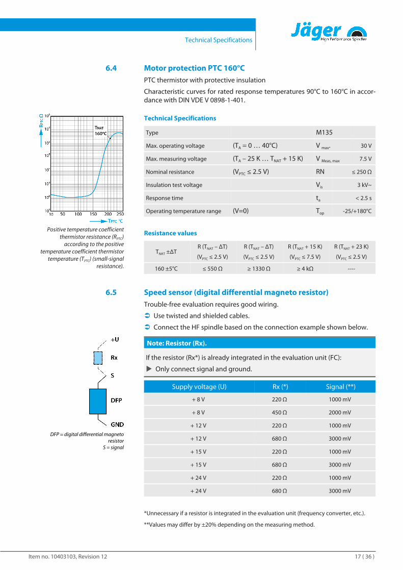
6.4 Motor protection PTC 160°CPTC thermistor with protective insulation
Characteristic curves for rated response temperatures 90°C to 160°C in accor-dance with DIN VDE V 0898-1-401.
Positive temperature coefficientthermistor resistance (RPTC)
according to the positivetemperature coefficient thermistor
temperature (TPTC) (small-signalresistance).
Technical Specifications
Type M135
Max. operating voltage (TA = 0 … 40°C) V max. 30 V
Max. measuring voltage (TA – 25 K … TNAT + 15 K) V Meas, max 7.5 V
Nominal resistance (VPTC ≤ 2.5 V) RN ≤ 250 Ω
Insulation test voltage Vis 3 kV~
Response time ta < 2.5 s
Operating temperature range (V=0) Top -25/+180°C
Resistance values
TNAT ±ΔTR (TNAT – ΔT)
(VPTC ≤ 2.5 V)
R (TNAT – ΔT)
(VPTC ≤ 2.5 V)
R (TNAT + 15 K)
(VPTC ≤ 7.5 V)
R (TNAT + 23 K)
(VPTC ≤ 2.5 V)
160 ±5°C ≤ 550 Ω ≥ 1330 Ω ≥ 4 kΩ ----
6.5 Speed sensor (digital differential magneto resistor)Trouble-free evaluation requires good wiring.
Ü Use twisted and shielded cables.
Ü Connect the HF spindle based on the connection example shown below.
DFP = digital differential magnetoresistor
S = signal
Note: Resistor (Rx).
If the resistor (Rx*) is already integrated in the evaluation unit (FC):
u Only connect signal and ground.
Supply voltage (U) Rx (*) Signal (**)
+ 8 V 220 Ω 1000 mV
+ 8 V 450 Ω 2000 mV
+ 12 V 220 Ω 1000 mV
+ 12 V 680 Ω 3000 mV
+ 15 V 220 Ω 1000 mV
+ 15 V 680 Ω 3000 mV
+ 24 V 220 Ω 1000 mV
+ 24 V 680 Ω 3000 mV
*Unnecessary if a resistor is integrated in the evaluation unit (frequency converter, etc.).
**Values may differ by ±20% depending on the measuring method.
Technical Specifications
Item no. 10403103, Revision 1218 ( 36 )
6.6 ESD protectionESD protection is provided by creating an electrically conductive connectionbetween the rotating shaft of the HF spindle and the motor housing.
q Depending on the operating time, the electrical resistance of this slidingcontact is <1 kΩ.
q The wear on the sliding contact is not monitored.
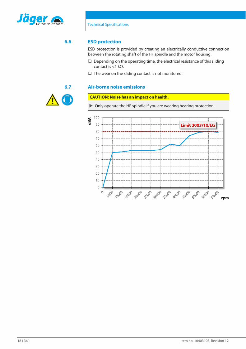
6.7 Air-borne noise emissions
CAUTION: Noise has an impact on health.
u Only operate the HF spindle if you are wearing hearing protection.
Operating location
Item no. 10403103, Revision 12 19 ( 36 )
7 Operating location
DANGER: Due to flying parts.
If the HF spindle is incorrectly attached, it may come loose during operationand be flung away by the forces that occur.
u Clamp the HF spindle firmly.
WARNING: Risk of injury due to flying parts.
The HF spindle operates at high speeds which may cause chips to fly outwith great force.
u Never remove the protective devices of the machine or system.
u Always wear protective goggles during work.
Example of design: Mountingsurface
Note the following points before installing the HF spindle:
Ü Make sure that the correct spindle holder for the HF spindle is fitted in themachine.
Ü Check the connecting hoses for damage.
Ü Check the connecting cables for damage.
Ü Only use undamaged hoses and cables.
Ü Do not allow the HF spindle to run in the vicinity of a heat source.

Installation
Item no. 10403103, Revision 1220 ( 36 )
8 InstallationBefore installation:
Ü Check the HF spindle for damage and ensure that it is complete.
If the HF spindle has been stored for a long period:
Ü Carry out all steps in the Commissioning after storage [} 24] section.
8.1 Installing the HF spindle
Connect media and cables with aflexible connection.
Complete the following steps in sequence to install the HF spindle:
Ü Remove the sealing plugs that protect the connections against damageand contamination during transportation.
Ü Instead of these sealing plugs, install the appropriate hose fittings.
Ü Install the corresponding hoses in the hose fittings
Ü Make sure that the connections are flexible and free of strain.
Ü Seal all connections for compressed air axially in relation to the tighteningdirection.
Ü Seal all connections for cooling water axially in relation to the tighteningdirection.
Ü If the HF spindle is equipped with sealing air:
Ä Make sure that no air flow can occur in the bearing area.
Ä Always use sealed cable boxes when connecting electrical lines.
Ü Mount the HF spindle on the machine.
Ü Connect the hoses to the connection of the respective media.
Ü Connect the connector of the operating connection lines to the relevantconnection of the HF spindle and to the frequency converter.
Ü Lock the connectors.
Installation
Item no. 10403103, Revision 12 21 ( 36 )
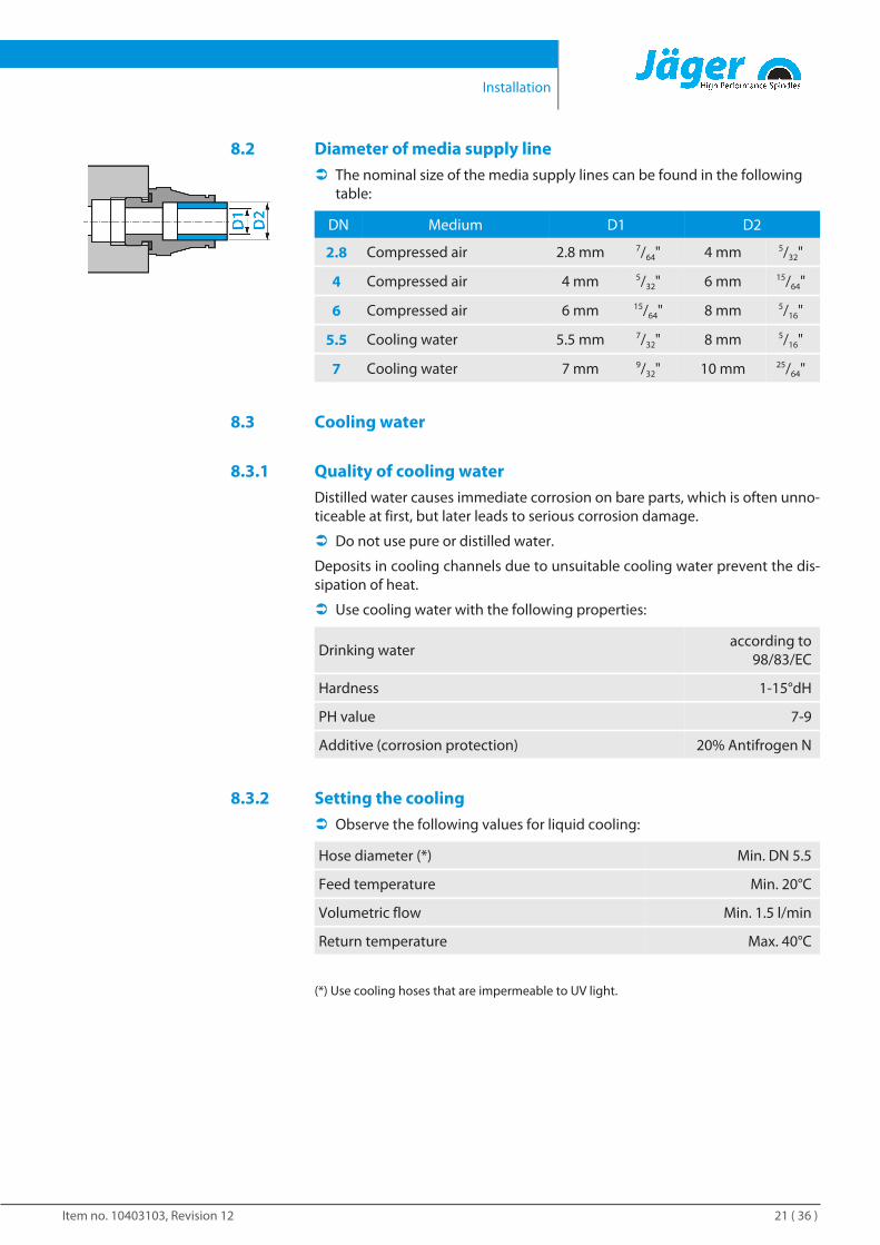
8.2 Diameter of media supply lineÜ The nominal size of the media supply lines can be found in the following
table:
DN Medium D1 D2
2.8 Compressed air 2.8 mm 7/64" 4 mm 5/32"
4 Compressed air 4 mm 5/32" 6 mm 15/64"
6 Compressed air 6 mm 15/64" 8 mm 5/16"
5.5 Cooling water 5.5 mm 7/32" 8 mm 5/16"
7 Cooling water 7 mm 9/32" 10 mm 25/64"
8.3 Cooling water
8.3.1 Quality of cooling waterDistilled water causes immediate corrosion on bare parts, which is often unno-ticeable at first, but later leads to serious corrosion damage.
Ü Do not use pure or distilled water.
Deposits in cooling channels due to unsuitable cooling water prevent the dis-sipation of heat.
Ü Use cooling water with the following properties:
Drinking wateraccording to
98/83/EC
Hardness 1-15°dH
PH value 7-9
Additive (corrosion protection) 20% Antifrogen N
8.3.2 Setting the coolingÜ Observe the following values for liquid cooling:
Hose diameter (*) Min. DN 5.5
Feed temperature Min. 20°C
Volumetric flow Min. 1.5 l/min
Return temperature Max. 40°C
(*) Use cooling hoses that are impermeable to UV light.
Installation
Item no. 10403103, Revision 1222 ( 36 )
8.4 Compressed air
8.4.1 Air purity classes (ISO 8573-1)
Solid impuritiesClass 3
Filter grade at least 5 µm for solids
Water contentClass 4
Max. pressure dew point +3 °C
Total oil contentClass 3
Max. oil content 1 mg/m3
8.4.2 Setting the sealing airFor guidelines on air quality, see"Air purity classes (ISO 8573-1)[} 22]" section.
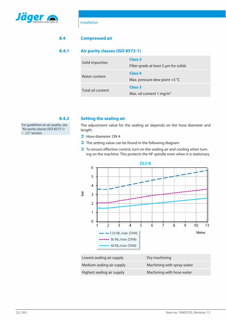
The adjustment value for the sealing air depends on the hose diameter andlength.
Ü Hose diameter: DN 4
Ü The setting value can be found in the following diagram.
Ü To ensure effective control, turn on the sealing air and cooling when turn-ing on the machine. This protects the HF spindle even when it is stationary.
Lowest sealing air supply Dry machining
Medium sealing air supply Machining with spray water
Highest sealing air supply Machining with hose water
Commissioning
Item no. 10403103, Revision 12 23 ( 36 )
8.4.3 Setting valuesFor guidelines on air quality, see"Air purity classes (ISO 8573-1)[} 22]" section.
Ü Keep to the following values:
Taper cleaning 4,5 - 6 bar
Pneumatic system for tool change 6 bar
9 Commissioning
DANGER: Due to flying parts.
If the speed is selected incorrectly, the HF spindle or the tool may be de-stroyed and their fragments may be flung out.
u Note the maximum speed for the selected tool.
u Note the maximum speed for the HF spindle.
u Always select the lowest specified speed for machining.
Example of design: Inserting theshank
Note: Ensure functionality.
u Never operate the HF spindle without a clamped tool shank.
If no tool shank is clamped:
q The clamping system is damaged by the centrifugal forces.
q The clamping system is shifted.
q The balance of the HF spindle is affected.
q The bearing is damaged.
Example of design: Clockwise
Ü Turn the shaft of the spindle at least ten times by hand.
Ü Before storing and before commissioning only clean the cooling duct withcompressed air.
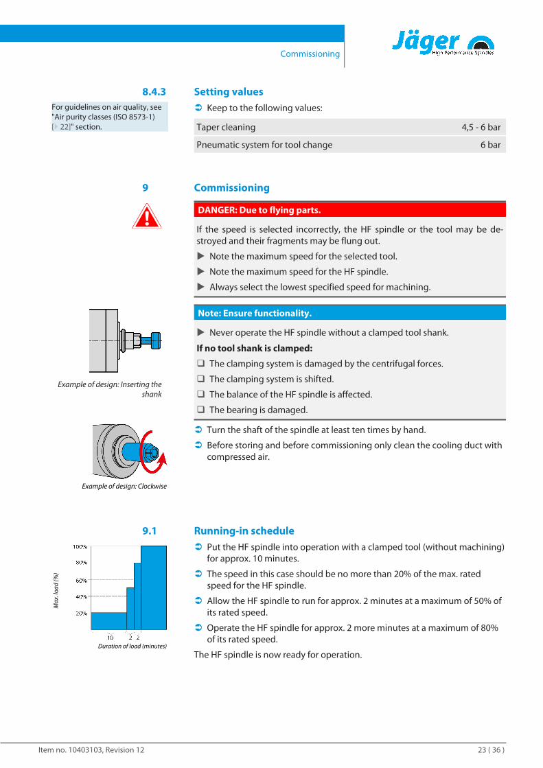
9.1 Running-in schedule
Duration of load (minutes)
Max
. loa
d (%
)
Ü Put the HF spindle into operation with a clamped tool (without machining)for approx. 10 minutes.
Ü The speed in this case should be no more than 20% of the max. ratedspeed for the HF spindle.
Ü Allow the HF spindle to run for approx. 2 minutes at a maximum of 50% ofits rated speed.
Ü Operate the HF spindle for approx. 2 more minutes at a maximum of 80%of its rated speed.
The HF spindle is now ready for operation.
Commissioning
Item no. 10403103, Revision 1224 ( 36 )
9.2 Daily start-upProceed as follows to preheat the grease lubrication of the bearing and toprotect it:
Ü Operate the HF spindle with a clamped tool (without machining).
Ä Approx. 2 minutes.
Ä With maximum 50 % of rated speed.
This brings the HF spindle to its operating temperature.
9.3 Shutdown signalUse the option on the frequency converter of detecting the shutdown signalfrom the shaft and forwarding this to the machine controller for evaluation.
9.4 Commissioning after storageÜ Do not put the HF spindle into operation until its temperature has adjusted
from the temperature of the storage location to the temperature of the us-age location.
Ä The temperature difference between the HF spindle and the usage lo-cation should not exceed 10°C.
Ü Carry out all steps in the "Maintenance [} 29] / Long periods of storage[} 30]" section.
Ü Operate the HF spindle with a maximum of 50% of the max. rated speedfor approx. 5 minutes.
Ü Operate the HF spindle for approx. 2 more minutes at a maximum of 80%of its rated speed.
This preheats the grease lubrication of the bearing and protects it.
Tool change
Item no. 10403103, Revision 12 25 ( 36 )
10 Tool change
CAUTION: Danger of being drawn in by rotating shaft.
If the shaft is still rotating, fingers and hands may be drawn in and crushed.
u Only change the tool if the shaft is at a standstill.
Example of design: Inserting theshank
Note: Ensure functionality.
u Never operate the HF spindle without a clamped tool shank.
If no tool shank is clamped:
q The clamping system is damaged by the centrifugal forces.
q The clamping system is shifted.
q The balance of the HF spindle is affected.
q The bearing is damaged.
10.1 pneumatic taper change
Tip: Ensure concentric run-out quality.
u Keep collet, clamping nut, contact surface, shaft, tool taper, and toolmount clean at all times.
u Check the tool taper mount.
It must be free of damage and clean when switching to the HF spindle.
Ü Make sure that the shaft of the HF spindle has come to an absolute stand-still.
Ü Switch on the compressed air for the tool change.
Ü Remove the tool mount.
Ü Clean the inner taper of the tool mount and the inner taper of the shaftwith the felt cleaning taper.
Ü Insert the tool mount.
Ü Switch off the compressed air for the tool change.
Ü Wait for 1-2 seconds after the tool change.
Ü Start the HF spindle.
Tool change
Item no. 10403103, Revision 1226 ( 36 )
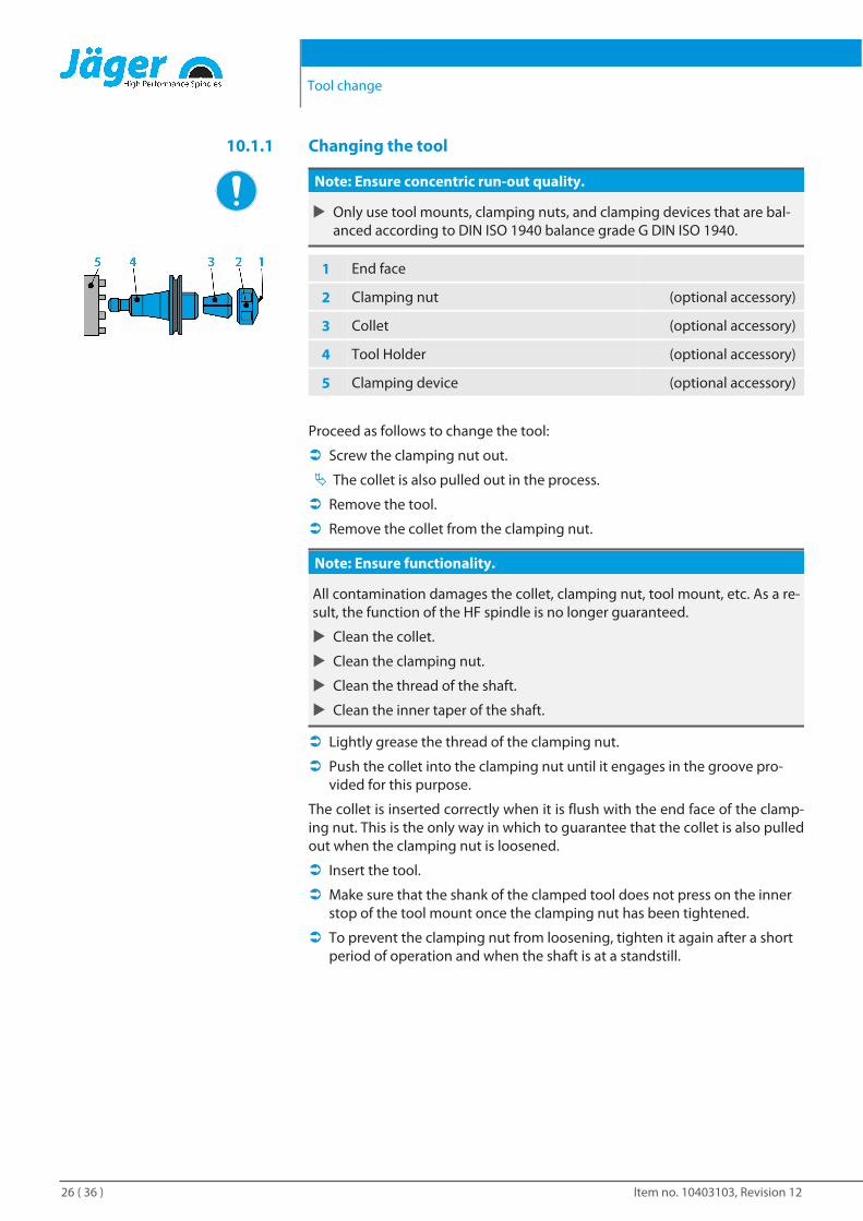
10.1.1 Changing the tool
Note: Ensure concentric run-out quality.
u Only use tool mounts, clamping nuts, and clamping devices that are bal-anced according to DIN ISO 1940 balance grade G DIN ISO 1940.
1 End face
2 Clamping nut (optional accessory)
3 Collet (optional accessory)
4 Tool Holder (optional accessory)
5 Clamping device (optional accessory)
Proceed as follows to change the tool:
Ü Screw the clamping nut out.
Ä The collet is also pulled out in the process.
Ü Remove the tool.
Ü Remove the collet from the clamping nut.
Note: Ensure functionality.
All contamination damages the collet, clamping nut, tool mount, etc. As a re-sult, the function of the HF spindle is no longer guaranteed.
u Clean the collet.
u Clean the clamping nut.
u Clean the thread of the shaft.
u Clean the inner taper of the shaft.
Ü Lightly grease the thread of the clamping nut.
Ü Push the collet into the clamping nut until it engages in the groove pro-vided for this purpose.
The collet is inserted correctly when it is flush with the end face of the clamp-ing nut. This is the only way in which to guarantee that the collet is also pulledout when the clamping nut is loosened.
Ü Insert the tool.
Ü Make sure that the shank of the clamped tool does not press on the innerstop of the tool mount once the clamping nut has been tightened.
Ü To prevent the clamping nut from loosening, tighten it again after a shortperiod of operation and when the shaft is at a standstill.
Tool change
Item no. 10403103, Revision 12 27 ( 36 )
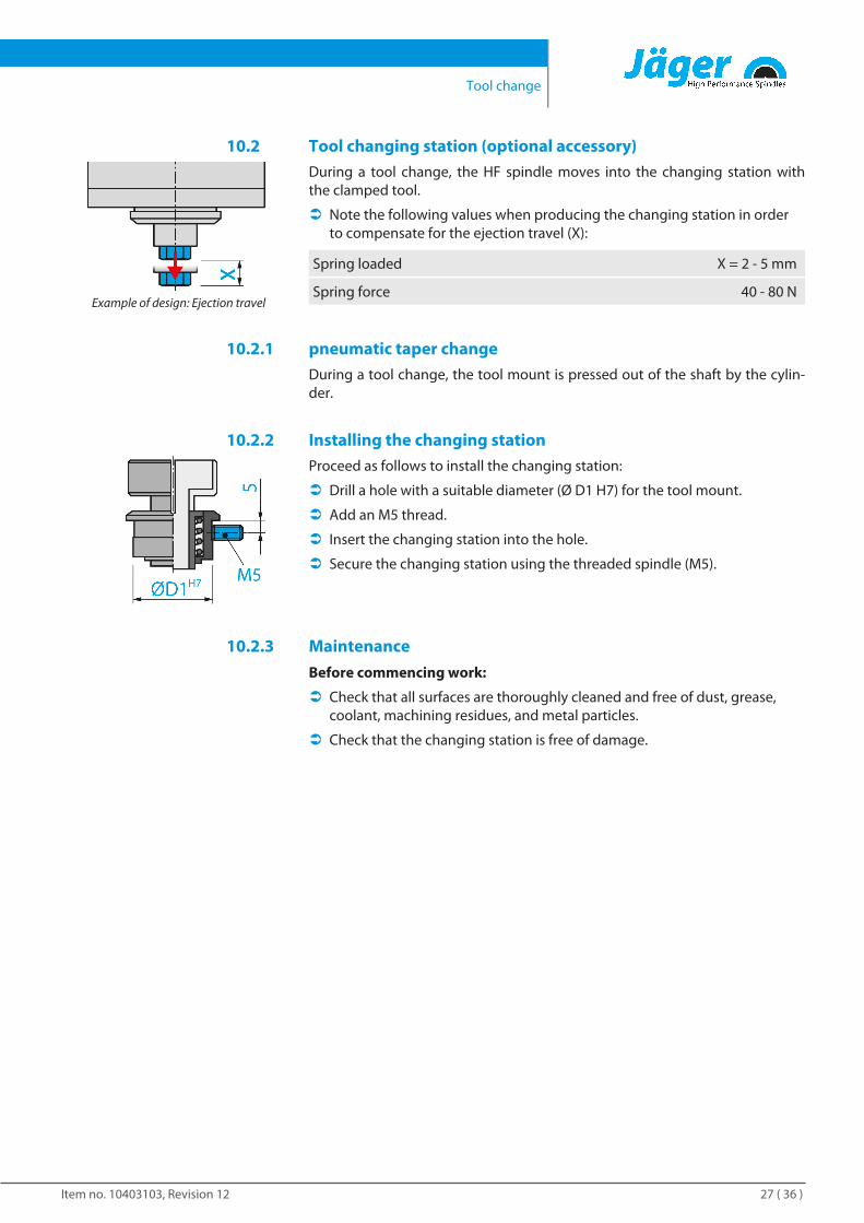
10.2 Tool changing station (optional accessory)
Example of design: Ejection travel
During a tool change, the HF spindle moves into the changing station withthe clamped tool.
Ü Note the following values when producing the changing station in orderto compensate for the ejection travel (X):
Spring loaded X = 2 - 5 mm
Spring force 40 - 80 N
10.2.1 pneumatic taper changeDuring a tool change, the tool mount is pressed out of the shaft by the cylin-der.
10.2.2 Installing the changing stationProceed as follows to install the changing station:
Ü Drill a hole with a suitable diameter (Ø D1 H7) for the tool mount.
Ü Add an M5 thread.
Ü Insert the changing station into the hole.
Ü Secure the changing station using the threaded spindle (M5).
10.2.3 MaintenanceBefore commencing work:
Ü Check that all surfaces are thoroughly cleaned and free of dust, grease,coolant, machining residues, and metal particles.
Ü Check that the changing station is free of damage.
Tools for high speed cutting
Item no. 10403103, Revision 1228 ( 36 )
11 Tools for high speed cutting
DANGER: Due to flying parts.
If the wrong direction of rotation is used, the tool is damaged when load isapplied. The centrifugal forces cause the broken part to be flung out.
u Only use tools with the correct direction of rotation for the HF spindle.
DANGER: Due to flying parts.
If the speed is selected incorrectly, the HF spindle or the tool may be de-stroyed and their fragments may be flung out.
u Note the maximum speed for the selected tool.
u Note the maximum speed for the HF spindle.
u Always select the lowest specified speed for machining.
Ü Only use tools that are technically sound.
Ü Only use tools with a tool shank diameter that corresponds to the inner di-ameter of the collet. For example, do not use shanks with a diameter of 3mm in collets for 1/8” (=3.175 mm).
Ä Also see the Technical Specifications [} 12] section
Ü Only use tool shanks with a diameter tolerance of h6.
Ü Only use mounts with a diameter tolerance of h6.
Ü Do not use tool shanks with a clamping surface (e.g. Weldon).
Ü Only use a balanced tool.
Ä DIN ISO 1940, balance grade 2,5 .
Maintenance
Item no. 10403103, Revision 12 29 ( 36 )
12 MaintenanceOnly specialist personnel may perform maintenance on the spindle.
The HF spindle must be shut down before any maintenance work.
Ü Make sure that the shaft of the HF spindle has come to an absolute stand-still.
Ü Before carrying out any work, read the corresponding section of the man-ual carefully again.
Ü Observe the manual of the machine in which the HF spindle is installed.
Ü Observe all safety instructions and safety rules.
12.1 Ball bearings
Note: Foreign matter reduces the service life.
The HF spindle bearings have lifetime grease lubrication. This means thatthey do not require maintenance.
u Do not lubricate the ball bearings.
u Do not apply grease, oil, or cleaning agents to the openings of the HFspindle.
12.2 Daily cleaningTo ensure that the HF spindle functions safely and accurately, all contact sur-faces of the HF spindle, the mount for the HF spindle, the tool mount, and thetool holder must be clean.
Note: Foreign matter reduces the service life.
u Do not use compressed air to clean the HF spindle.
u Do not use ultrasonic cleaning on the HF spindle.
u Do not use steam jets to clean the HF spindle.
This could cause contamination to enter the bearing area.
12.2.1 Before commencing workÜ Check that all surfaces are thoroughly cleaned and free of dust, grease,
coolant, machining residues, and metal particles.
Ü Check that the HF spindle is free of damage.
Ü If the HF spindle is equipped with sealing air, always switch this on duringcleaning.
Ü Only use a clean, soft cloth or a clean, soft brush for cleaning.
If the HF spindle is equipped with taper cleaning:
Ü Switch the taper cleaning on for 2-3 seconds after cleaning.
This means that any contamination that is still stuck to the shaft is blown outby the taper cleaning air.
Maintenance
Item no. 10403103, Revision 1230 ( 36 )
12.2.2 With every tool changeÜ Clean the inner taper of the HF spindle shaft. The inner taper must be free
of chips and contamination.
Ü Clean the tool taper.
Ü Clean the collet and the collet mount.
Ü Apply a light greasy film to the taper of the collet after cleaning.
Ä Only use the collet grease from the service set.
This improves the sliding movement and increases the clamping force of thecollet.
12.3 In the case of storageIf the HF spindle is not required for a prolonged period of time:
Ü Before storing and before commissioning only clean the cooling duct withcompressed air.
Ü Remove all coolant residues.
Ü Store the HF spindle in horizontal position.
Ü Store the HF spindle so that it is protected from moisture, dust, and otherenvironmental influences.
Ü Note the following storage conditions.
Temperature of storage location +10°C … + 45° C
Relative humidity < 50 %
12.4 Monthly maintenanceÜ Turn the shaft of the HF spindle at least ten times by hand every four
weeks.
12.5 Long periods of storageÜ Turn the shaft of the HF spindle at least ten times by hand every three
months.
Ü Then put the HF spindle into operation with a tool inserted for approx.10 minutes.
Ä The speed in this case should be no more than 20% of the max. ratedspeed for the HF spindle.
12.6 Maximum storage timeThe maximum storage time is 2 years.
Ü Make sure that all information in the "Long periods of storage [} 30]" sec-tion is adhered to. This is the only way in which to maintain the functional-ity of the HF spindle.
Dismantling
Item no. 10403103, Revision 12 31 ( 36 )
13 DismantlingProceed as follows to remove the HF spindle:
Ü Completely disconnect the power supply.
Ü Completely disconnect the media supply (air and liquid).
Ü Make sure that the shaft of the HF spindle has come to an absolute stand-still.
Ü Remove all connections from the HF spindle.
Ü Empty the cooling duct of the HF spindle.
Ü Remove the HF spindle from the machine.
13.1 Disposal and environmental protectionMore than 90% of the materials used in the HF spindle can be recycled (alu-minum, stainless steel, steel, copper, etc.)
The HF spindle may not be disposed of with normal domestic waste.
Ü Remove all non-recyclable materials.
Ü Dispose of the HF spindle as scrap at an approved recycling facility.
Ü Follow all rules of the responsible administrative bodies.
Ü Do not discharge coolants into wastewater.
Ü Dispose of cooling media in accordance with local regulations.
If the HF spindle cannot be dismantled, send the HF spindle to Alfred JägerGmbH. Alfred Jäger GmbH shall not assume the costs incurred for shipmentand the fees for the recycling facilities.
14 Service and repairs
DANGER: Electric shock.
Electric shock can lead to severe burns and life-threatening injuries.
Take measures to prevent hazards caused by electrical energy (for details re-fer e.g. to the regulations issued by the VDE and the local energy supplycompanies).
u Before commencing work, switch off the power supply of the HF spindle.
Note: Damage due to electrostatic discharge.
Do not touch the electrostatic-sensitive components of the HF spindle.
14.1 Service partnersOnly certified service partners may open and repair the spindle. Failure tocomply with this voids any warranty claims and compensation claims for dam-ages.
Ü The list of partners can be found on the following website.
http://www.alfredjaeger.de/de/spindel-servicepartner.html
Service and repairs
Item no. 10403103, Revision 1232 ( 36 )
14.2 MalfunctionsThe list below can be used to quickly investigate and eliminate faults.
HF spindle not rotating Cause Troubleshooting
No power supply
q Check the frequency converter.
q Check the machine.
q Check all electrical connections.
q Check all wires in the motor cable.
q Activate the Start/Reset button.
Thermal protection hasbeen activated
q Wait until the HF spindle has cooled down.
q Check the frequency converter for error messages. If nomessages are illuminated, start the frequency converter.
(See also “Spindle becomes hot [} 32]”.)
Frequency converterhas shut down
q Check the error messages in the frequency converter man-ual.
Tool change initiated q Turn off the pneumatic system for the tool change.
HF spindle becomes hot Cause Troubleshooting
Insufficient cooling
q Check the power of the chiller.
q Check the water level of the chiller.
q Check the connections and the cooling hoses.
q Check the cooling circuit.
q Check the chiller for error messages.
Phase missing q Check all wires in the motor cable for cable breaks.
Machining too heavy
q Check the rotational direction of the HF spindle.
q Check the rotational direction of the tool.
q Check the tool for damage.
q Reduce the machining load intensity.
Frequency converterincorrectly set
q Compare the values for the HF spindle with the set valueson the frequency converter.
HF spindle becomes loud Cause Troubleshooting
Tool unsuitable
q Only use balanced tools.
(Also see the "Tools for high speed cutting [} 28]" section.)
q Check the tool for damage.
q Replace damaged tool.
HF spindle is notclamped truly or is dis-torted
q Only use spindle holders from the original accessories orholders produced according to the tolerances specified byAlfred Jäger GmbH.
HF spindle clampedtoo tightly
q Only tighten the clamping screws of the spindle holdermanually.
q Do not use technical aids to clamp the HF spindle.
Bearings damaged q Contact Alfred Jäger GmbH service.
Service and repairs
Item no. 10403103, Revision 12 33 ( 36 )
No automatic tool change Cause Troubleshooting
Contamination
q Remove all contamination between the tool taper andshaft of the HF spindle.
(Observe all points in the “Tool change [} 25]” and “Mainte-nance [} 29]” sections.)
Lack of pressure
q Check the connections for compressed air.
q Check the hoses for compressed air.
q Check the pneumatic circuit.
q Check the setting of the compressed air for the toolchange.
(Also see the "Setting values [} 23]" section.)
Sensor does not send anysignals
Cause Troubleshooting
No connection to sen-sor q Check the lines and connections.
HF spindle vibrates/oscillates
Cause Troubleshooting
Tool unsuitable
q Only use balanced tools.
(Also see the "Tools for high speed cutting [} 28]" section.)
q Check whether the tool is suitable for the application.
q Check the tool for damage.
q Replace damaged tool.
Contamination
q Remove all contamination between the tool taper and shaftof the HF spindle.
(Observe all points in the “Tool change [} 25]” and “Mainte-nance [} 29]” sections.)
Frequency converterincorrectly set
q Compare the values for the HF spindle with the set values onthe frequency converter.
Machining too heavy q Reduce the machining load intensity.
Mounting screws areloose q Tighten the screws securely.
HF spindle damaged q Contact Alfred Jäger GmbH service.
If the error is not rectified after checking all of the points, contact the relevantservice partner.
Ü Request the accompanying note for the repair from the service partner.
Ü Check the manual of the machine.
Ü Contact the manufacturer of the machine.
Warranty
Item no. 10403103, Revision 1234 ( 36 )
15 WarrantyIn the case of legitimate complaints that relate to the goods and are recog-nized by the supplier, repair or redelivery must be performed according to thereasonably exercised discretion of the supplier for all parts that are renderedunusable or that are significantly impaired in terms of their usability prior to2000 operating hours having elapsed – in the case of Jäger spindles, whichfeature an integrated meter – according to the meter reading of the dedicatedmeter for the spindle in question, or within 12 months of delivery, i.e. follow-ing the delivery of the delivery item, and as a result of an issue that waspresent prior to the transfer of risk, especially due to defective design, poor-quality building materials, or faulty equipment.
Complaints regarding visible defects must be reported to the supplier within10 days after receipt of the product.
No liability is accepted for damage caused by the following: Unsuitable ornon-designated use, incorrect installation or commissioning by the customeror third parties, natural wear and tear of wearing parts, particularly ball bear-ings, incorrect or negligent handling, inappropriate operating media, chemi-cal electro-chemical or electrical influences, where these cannot be attributedto a fault on the part of the supplier. Otherwise, our general terms and condi-tions of business apply, in particular section VII “Liability for defects and war-ranty”. Unless agreed separately, the customer is liable for all other costs, par-ticularly all shipping costs.
We reserve the right to make changes to the design without prior notificationor special indication.
We reserve the right to carry out renovations to spindles during repairs to re-flect the latest technological advances.
Likewise, the supplier bears no liability if the customer or a third party makesimproper modifications or carries out unauthorised repair work on the prod-uct without the prior approval of the supplier.
Declaration of Incorporation
Item no. 10403103, Revision 12 35 ( 36 )
16 Declaration of IncorporationUnder the EC Machinery Directive
The safety instructions of theproduct documentation suppliedmust be observed.
Alfred Jäger GmbH
SF-Elektromaschinenbau
Siemensstr. 8
D-61239 Ober-Mörlen
Tel. +49 (0) 60029123 -0
hereby declare that the product,
Product High Frequency Spindle
Type Z62-K360.12 S4A
Serial no. See last page of manual
as far as possible from the supplied, complies with the essential requirementsof the Machinery Directive 2006/42/EC.
Sections of the Machinery Directive have been applied: 1.1.1; 1.1.2; 1.1.5; 1.3.2;1.3.4; 1.5.1; 1.5.2; 1.5.4; 1.5.5; 1.5.6; 1.5.8; 1.5.9; 1.6.4; 1.6.5; 1.7.1; 1.7.1.1; 1.7.2;1.7.3; 1.7.4;
The incomplete machinery in its standard design complies furthermore withthe following applicable regulations:
Applicable harmonized standardsDIN EN ISO 12100
Safety of machines
The machinery is incomplete and must not be put into service until the ma-chinery into which it is to be incorporated has been declared in conformitywith the provisions of the Machinery Directive 2006/42/EC and any other ap-plicable regulations.
We at Alfred Jäger GmbH agree to submit the special documents for incom-plete machines to national authorities upon request.
The special technical documentation referred to in Annex VII, Part B, belong-ing to the machine has been created.
Person who is authorized to compile the documents listed in Annex VII, Part B:
Alfred Jäger GmbH
Ober-Mörlen, 04.06.2018Place and date of issue
Bernd JägerExecutive Board
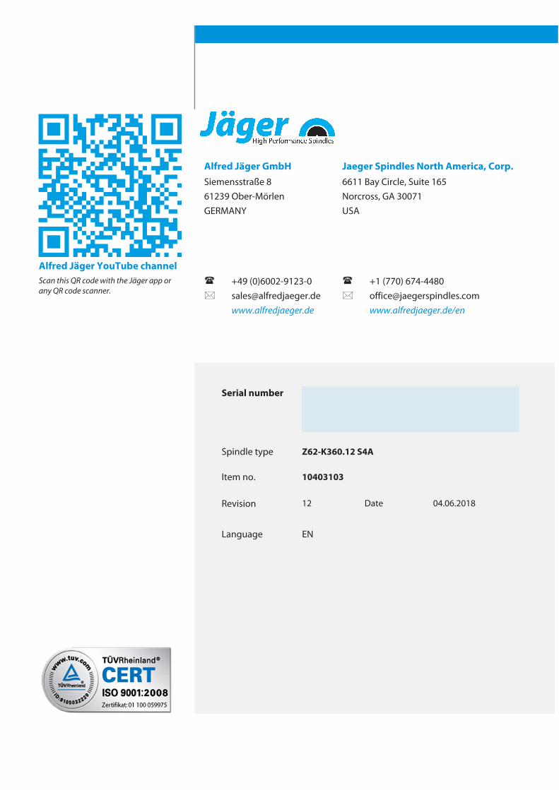
Alfred Jäger YouTube channelScan this QR code with the Jäger app orany QR code scanner.
Alfred Jäger GmbHSiemensstraße 861239 Ober-MörlenGERMANY
+49 (0)[email protected]
Serial number
Spindle type Z62-K360.12 S4A
Item no. 10403103
Revision 12 Date 04.06.2018
Language EN
(
*
Jaeger Spindles North America, Corp.6611 Bay Circle, Suite 165Norcross, GA 30071USA
(
*
+1 (770) [email protected]/en