high-fidelity optimization of flapping airfoils and...
TRANSCRIPT
High-Fidelity Optimization of Flapping Airfoils and
Wings
Matthew Culbreth,� Yves Allaneau� and Antony Jamesony
Stanford University, Stanford, CA 94305, USA
We present the results of several optimizations for 2D airfoils and 3D wings undergoingperiodic, apping-type motions. Optimizations are achieved by coupling high-�delity 2Dand 3D Navier-Stokes solvers with a gradient-based optimization algorithm. In 2D weconsider a pitching and plunging NACA0012 airfoil and investigate the maximization ofthe propulsive e�ciency. In 3D we consider a rectangular wing that is hinged at the root.The motion of the 3D wing is parameterized by spline control points that allow span-wisevariation of both the dihedral angle and twist angle, allowing complex wing motions anddeformations with relatively few parameters. Propulsive e�ciency is maximized for the3D wing in an non-twisting case as well as using one, two and four of these span-wise twistcontrol points. The results of the optimizations lead to several conclusions, including thatpitching and twisting can signi�cantly improve the attainable propulsive e�ciency, candelay the onset of leading edge separation, and that solutions that maximize propulsivee�ciency appear to operate at the limit of leading edge separation.
Nomenclature
f Frequency of oscillation� Pitch Angle (2D) and twist angle (3D)� Dihedral Angle (3D)h Plunging amplitude (2D)� Phase o�set corresponding to � Phase o�set corresponding to ��m Modi�ed propulsive e�ciencyP Aerodynamic powerCL Lift coe�cientCD Drag coe�cientx Vector of optimization parametersf(x) Optimization objective functiong(x) Non-linear constrain functionsAx Linear optimization constraintsl Lower optimization constrain boundu Upper optimization constrain bound
Subscriptx; y; z Coordinate directionsk; l Value at kth or lth control points for the dihedral or twist angle, respectively
�Doctoral Candidate, Department of Aeronautics & Astronautics, Stanford University, AIAA MemberyProfessor, Department of Aeronautics & Astronautics, Stanford University, AIAA Fellow
1 of 11
American Institute of Aeronautics and Astronautics
29th AIAA Applied Aerodynamics Conference27 - 30 June 2011, Honolulu, Hawaii
AIAA 2011-3521
Copyright © 2011 by M. Culbreth. Published by the American Institute of Aeronautics and Astronautics, Inc., with permission.
I. Introduction
There has been a signi�cant increase in research interest in the aerodynamics of apping wings withinthe last decade. Flapping wing ight has become a signi�cant engineering research direction, with theminiaturization of electronic components and increases in battery energy density allowing for the creation ofa class of small-scale unmanned ying vehicles generally referred to as micro air vehicles (MAVs). Flappingwings are of particular interest for this application both because of the numerous, highly-successful examplesof apping wing ight found in nature and because apping wings provide an attractive ight system thatprovides lifting, thrust and control in a single package. Investigation of apping wing ight is also ofsigni�cant importance to the fundamental science of aerodynamics. The development of aircraft over thelast century has provided a signi�cant and mature body of understanding of the physics of steady-state uid dynamics across a wide range of ight speeds. This work generally has little application, however, tothe complex and unsteady apping wing ight regime. Fortunately, high-�delity computational tools andassociated powerful computational hardware now allow for accurate simulation of apping wings, makingit possible to begin to understand the physics of this type of ight. These high-�delity simulation toolshave also opened new possibilities for research into the uid dynamics of bird and insect ight within thebiology community. These tools now allow detailed examination in areas such as the relationship between thekinematics and the resulting forces such as lift and thrust and the ow physics associated with the numerousexamples of animal ight mechanisms.
Flapping wing ight is complex and di�cult from a research and design stand-point. As previouslymentioned, very few of the e�cient computational design tools used for large aircraft design can be used inthe unsteady, low Reynolds number regime. Accurate simulation of apping wings requiring costly unsteadynumerical ow simulations that can accommodate large mesh motions and deformations and feature lownumerical dissipation to accurately capture the complex, vortex dominated ow physics. A second di�cultyis that there are many degrees of freedom in the parameterization of apping wing motions when consideringa exible wing in a generalized periodic apping motion. While much has been learned from observing the ight of birds and insects, it is still far from clear how to couple wing exibility and apping motion in ane�cient or optimal way for a given ight performance metric. Additionally, it is not clear how to compactlyparameterize apping wing motion while still retaining the appropriate level of complexity of motion requiredfor e�cient ight.
We propose to address the issues associated with selecting an appropriate parameterization and thenidentifying the parameter values that yield e�cient performance by using a numerical optimization process.We have developed 2D and 3D viscous ow solvers that are speci�cally tailored to simulating a appingwing. These codes are coupled to a gradient-based numerical optimization algorithm. The optimizationprocess is then used in conjunction with parameterizations of varying complexity to both identify optimal apping motions and also investigate the trade-o� between the complexity of the motion and the attainableperformance. In this paper we speci�cally address the optimization of propulsive e�ciency in the 2D and3D case. In 2D we investigate the pitching and plunging airfoil case. In 3D we investigate a apping andtwisting wing that is hinged at the wing root and has varying degrees of complexity of span-wise twist. Wecompare the results of these optimizations both to understand the attainable limits of propulsive e�ciencyand the cost versus bene�t of adding additional degrees of freedom to the wing motion.
Background
The study of apping wings dates back to the beginnings of the study of aerodynamics itself , with attemptsat constructing apping wing vehicles that predate the �rst powered aircraft. The development of thetheory of apping wings through the twentieth century was somewhat of a footnote in the evolution ofaerodynamic theory, which was largely driven by understanding transonic and supersonic �xed-wing ight.Early examples of apping wing theory come from the work of Theodorsen1 and Garrick,2 who developedanalytic models for airfoils undergoing small-amplitude oscillations in 2D potential ow, work that waslargely motivated by attempts to understand aeroelastic utter. Lighthill3 and Weis-Fogh,4 among others,performed pioneering research on the aerodynamics of biological iers including the elucidation of some of thecomplex aerodynamic mechanisms used by these creatures. Interest in apping ight increased signi�cantlytowards the end of the twentieth century as steady aerodynamic theory reached maturity and improvementsin algorithms for computational uid dynamics (CFD) and increasing computing power made higher-�delitysimulations of apping wings possible. Early numerical simulations of apping wings were carried out using
2 of 11
American Institute of Aeronautics and Astronautics
unsteady vortex-lattice and panel methods.5,6 Current computational capabilities allow for high-�delity,3D, unsteady Navier-Stokes simulations of apping wings. A number of detailed CFD studies have beencompleted, including work by Jones, et. al.,7,8 Shyy et. al.,11 Persson et. al.,9 and Ou et. al.10
There has also been long-standing research interest in optimization of apping ight, based partially onthe assumption that natural iers operate in a manner that is optimal in some sense. R.T. Jones12 developedan expression for the optimal lift distribution along the wing during apping motion by minimizing induceddrag for a given wing bending moment in potential ow. Hall and Hall13 compute the optimal span-wisecirculation distribution on a thrusting and lifting wing using a 1D integral solution in the small amplitude caseand a vortex-lattice code in the large amplitude case. Hamdaoui et. al14 use a multi-objective evolutionaryalgorithm coupled with analytic apping wing models to optimize various ight metrics. Ito15 couples avortex-lattice model with a hybrid optimization method that combines a genetic algorithm with a sequentialquadratic programming algorithm. Strang16 utilizes a vortex-lattice code in conjunction with the gradient-based optimization to investigate the optimal apping gait of a Pterosaur wing. Milano and Gharib17 couplea genetic algorithm to an experimental apparatus with a two degree of freedom apping rectangular plate tomaximize average lift force. Tuncer and Kaya18 use gradient-based optimization coupled with a 2D overset-grid Navier-Stokes solver to maximize thrust and propulsive e�ciency of a pitching and plunging airfoil.Willis et. al.19 uses a multi-�delity approach to optimize apping wing performance metrics. In their work, apping motions are generated using optimal wake vorticity distributions generated by a wake only method,which are then further re�ned using a panel method and �nally veri�ed using a Discontinuous Galerkin-based3D Navier-Stokes solver.
In this work we propose to couple a 3D Navier-Stokes solver with a gradient-based optimization in ordercreate a framework for investigating various combinations of apping motions and optimization objectives.The details of this framework and several optimization results are presented in the remained of this document.
II. Optimization Framework
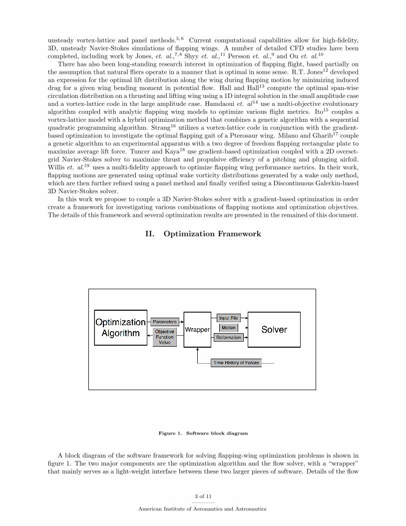
Figure 1. Software block diagram
A block diagram of the software framework for solving apping-wing optimization problems is shown in�gure 1. The two major components are the optimization algorithm and the ow solver, with a \wrapper"that mainly serves as a light-weight interface between these two larger pieces of software. Details of the ow
3 of 11
American Institute of Aeronautics and Astronautics
solver and optimization algorithm, as well as the formulation of the optimization problems are discussed inthe remainder of this section.
2D and 3D Navier-Stokes Solvers
The 2D and 3D ow solvers are based on the low-dissipation kinetic energy preserving (KEP) �nite volumescheme developed by Jameson20,21 and extended by Allaneau and Jameson.22 The kinetic energy preservingproperty of this scheme allows stability to be maintained with little or no arti�cial dissipation. This propertyis especially desirable for vortex dominated ows such as apping ight since arti�cial dissipation tends toquickly and unnaturally dampen complex ow features. These codes have been speci�cally developed tosimulate oscillating airfoils and apping wings and to be integrated into an optimization framework. Thefull details of this code can be found in the work of Allaneau et. al.23
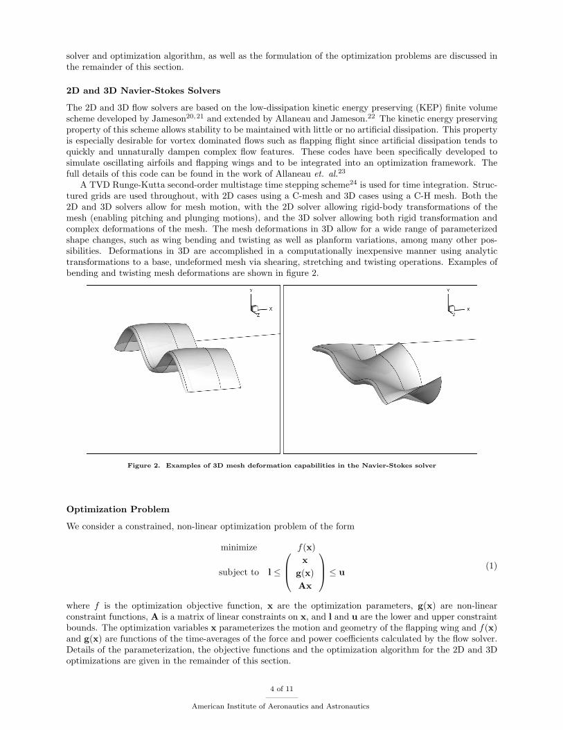
A TVD Runge-Kutta second-order multistage time stepping scheme24 is used for time integration. Struc-tured grids are used throughout, with 2D cases using a C-mesh and 3D cases using a C-H mesh. Both the2D and 3D solvers allow for mesh motion, with the 2D solver allowing rigid-body transformations of themesh (enabling pitching and plunging motions), and the 3D solver allowing both rigid transformation andcomplex deformations of the mesh. The mesh deformations in 3D allow for a wide range of parameterizedshape changes, such as wing bending and twisting as well as planform variations, among many other pos-sibilities. Deformations in 3D are accomplished in a computationally inexpensive manner using analytictransformations to a base, undeformed mesh via shearing, stretching and twisting operations. Examples ofbending and twisting mesh deformations are shown in �gure 2.
Figure 2. Examples of 3D mesh deformation capabilities in the Navier-Stokes solver
Optimization Problem
We consider a constrained, non-linear optimization problem of the form
minimize f(x)
subject to l �
0B@ xg(x)Ax
1CA � u(1)
where f is the optimization objective function, x are the optimization parameters, g(x) are non-linearconstraint functions, A is a matrix of linear constraints on x, and l and u are the lower and upper constraintbounds. The optimization variables x parameterizes the motion and geometry of the apping wing and f(x)and g(x) are functions of the time-averages of the force and power coe�cients calculated by the ow solver.Details of the parameterization, the objective functions and the optimization algorithm for the 2D and 3Doptimizations are given in the remainder of this section.
4 of 11
American Institute of Aeronautics and Astronautics
Parameterizations
In the 2D case we consider single-mode sinusoidal pitching and plunging motions. In the general case thesemotions take the form
�(t) = �0 + � cos(2�ft+ �) (2)
h(t) = h cos(2�ft) (3)
The parameterization used in all cases considered herein consists of four optimization variables: the frequencyf , the pitch and plunge amplitudes � and h and the phase di�erence between pitch and plunge �. The baseangle of attack �0 is set to zero in all cases, yielding motions that are symmetric about the axis of free-stream ow.
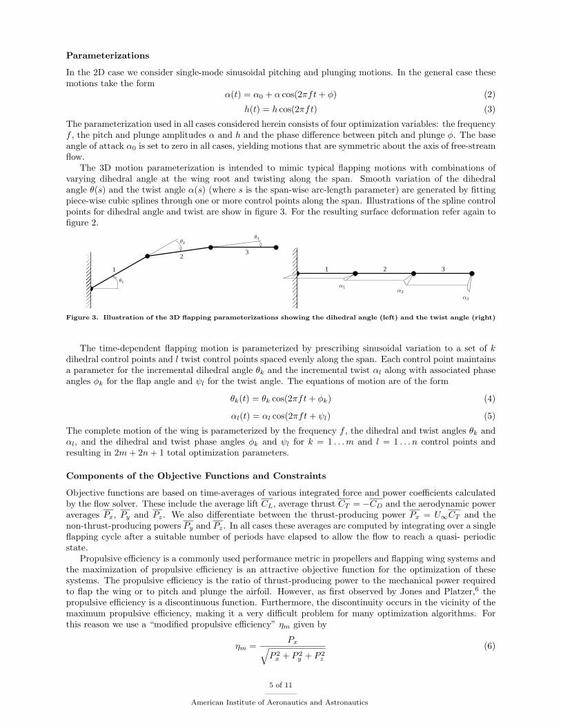
The 3D motion parameterization is intended to mimic typical apping motions with combinations ofvarying dihedral angle at the wing root and twisting along the span. Smooth variation of the dihedralangle �(s) and the twist angle �(s) (where s is the span-wise arc-length parameter) are generated by �ttingpiece-wise cubic splines through one or more control points along the span. Illustrations of the spline controlpoints for dihedral angle and twist are show in �gure 3. For the resulting surface deformation refer again to�gure 2.
����������
����������
23
1
θ2
θ3
θ1
����������
����������
2 31
α1α2
α3
Figure 3. Illustration of the 3D apping parameterizations showing the dihedral angle (left) and the twist angle (right)
The time-dependent apping motion is parameterized by prescribing sinusoidal variation to a set of kdihedral control points and l twist control points spaced evenly along the span. Each control point maintainsa parameter for the incremental dihedral angle �k and the incremental twist �l along with associated phaseangles �k for the ap angle and l for the twist angle. The equations of motion are of the form
�k(t) = �k cos(2�ft+ �k) (4)
�l(t) = �l cos(2�ft+ l) (5)
The complete motion of the wing is parameterized by the frequency f , the dihedral and twist angles �k and�l, and the dihedral and twist phase angles �k and l for k = 1 : : :m and l = 1 : : : n control points andresulting in 2m+ 2n+ 1 total optimization parameters.
Components of the Objective Functions and Constraints
Objective functions are based on time-averages of various integrated force and power coe�cients calculatedby the ow solver. These include the average lift CL, average thrust CT = �CD and the aerodynamic poweraverages Px, Py and Pz. We also di�erentiate between the thrust-producing power Px = U1CT and thenon-thrust-producing powers Py and Pz. In all cases these averages are computed by integrating over a single apping cycle after a suitable number of periods have elapsed to allow the ow to reach a quasi- periodicstate.
Propulsive e�ciency is a commonly used performance metric in propellers and apping wing systems andthe maximization of propulsive e�ciency is an attractive objective function for the optimization of thesesystems. The propulsive e�ciency is the ratio of thrust-producing power to the mechanical power requiredto ap the wing or to pitch and plunge the airfoil. However, as �rst observed by Jones and Platzer,6 thepropulsive e�ciency is a discontinuous function. Furthermore, the discontinuity occurs in the vicinity of themaximum propulsive e�ciency, making it a very di�cult problem for many optimization algorithms. Forthis reason we use a \modi�ed propulsive e�ciency" �m given by
�m =Pxq
P 2x + P 2
y + P 2z
(6)
5 of 11
American Institute of Aeronautics and Astronautics
This formulation removes the problem of a discontinuous objective function since, for all practical cases,qP 2
x + P 2y + P 2
z > 0.
Optimization Algorithm
A single objective function evaluation requires a time-accurate solution from the 2D or 3D ow solver. Thesesolutions are computed on large clusters and typically use between 64 and 512 compute cores. However, evenwith these signi�cant compute resources ow solutions take on the order of several hours. The signi�cantcomputational cost of objective function evaluations motivates the use of a gradient-based optimizationalgorithm since these methods tend to require far fewer evaluations of the objective functions than gradient-free methods such as genetic algorithms so long as the objective function is locally smooth near the optimum.We have chosen to use the SNOPT package25 for all of the optimizations presented here. SNOPT is a widelyused software library based on the sequential quadratic programming (SQP) method and is designed foruse on constrained, non-linear optimization problems. Gradients are computed within SNOPT via �nite-di�erences, which require on the order of n function evaluations per gradient calculation. The calculation ofthe gradients dominates the computational cost for all but the smallest problems, however since the functionevaluations within each gradient calculations are independent the process can be parallelized.
III. 2D Optimizations
For the 2D pitching and plunging airfoil case we consider the maximization of the modi�ed propulsivee�ciency using a NACA0012 airfoil at a Reynolds number of 1850 based on the chord and a mach numberof 0.2. The numerical solutions for all 2D cases use a 1024 � 128 C-mesh and are integrated over �ve periodsto ensure that the force and power reach a periodic state. The force and power coe�cients are integratedover the �nal oscillation cycle to obtain the averaged quantities for the objective function. The solver is runin parallel on a large cluster, typically using 64 compute cores per ow solution. Compute times are on theorder of 2 hours per ow solution. Optimal solutions are validated using a 4096�512 mesh that is e�ectivelyDNS resolution for the given Reynolds number.
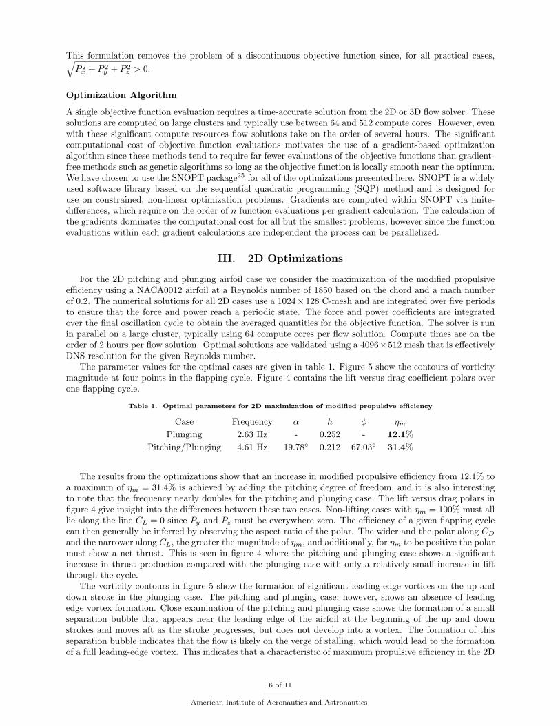
The parameter values for the optimal cases are given in table 1. Figure 5 show the contours of vorticitymagnitude at four points in the apping cycle. Figure 4 contains the lift versus drag coe�cient polars overone apping cycle.
Table 1. Optimal parameters for 2D maximization of modi�ed propulsive e�ciency
Case Frequency � h � �m
Plunging 2.63 Hz - 0.252 - 12:1%Pitching/Plunging 4.61 Hz 19:78� 0.212 67:03� 31:4%
The results from the optimizations show that an increase in modi�ed propulsive e�ciency from 12:1% toa maximum of �m = 31:4% is achieved by adding the pitching degree of freedom, and it is also interestingto note that the frequency nearly doubles for the pitching and plunging case. The lift versus drag polars in�gure 4 give insight into the di�erences between these two cases. Non-lifting cases with �m = 100% must alllie along the line CL = 0 since Py and Pz must be everywhere zero. The e�ciency of a given apping cyclecan then generally be inferred by observing the aspect ratio of the polar. The wider and the polar along CD
and the narrower along CL, the greater the magnitude of �m, and additionally, for �m to be positive the polarmust show a net thrust. This is seen in �gure 4 where the pitching and plunging case shows a signi�cantincrease in thrust production compared with the plunging case with only a relatively small increase in liftthrough the cycle.
The vorticity contours in �gure 5 show the formation of signi�cant leading-edge vortices on the up anddown stroke in the plunging case. The pitching and plunging case, however, shows an absence of leadingedge vortex formation. Close examination of the pitching and plunging case shows the formation of a smallseparation bubble that appears near the leading edge of the airfoil at the beginning of the up and downstrokes and moves aft as the stroke progresses, but does not develop into a vortex. The formation of thisseparation bubble indicates that the ow is likely on the verge of stalling, which would lead to the formationof a full leading-edge vortex. This indicates that a characteristic of maximum propulsive e�ciency in the 2D
6 of 11
American Institute of Aeronautics and Astronautics
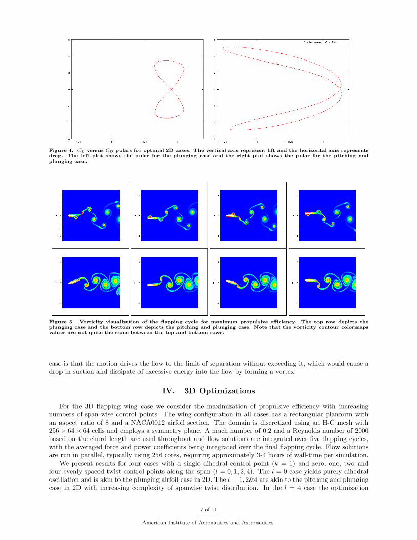
Figure 4. CL versus CD polars for optimal 2D cases. The vertical axis represent lift and the horizontal axis representsdrag. The left plot shows the polar for the plunging case and the right plot shows the polar for the pitching andplunging case.
Figure 5. Vorticity visualization of the apping cycle for maximum propulsive e�ciency. The top row depicts theplunging case and the bottom row depicts the pitching and plunging case. Note that the vorticity contour colormapsvalues are not quite the same between the top and bottom rows.
case is that the motion drives the ow to the limit of separation without exceeding it, which would cause adrop in suction and dissipate of excessive energy into the ow by forming a vortex.
IV. 3D Optimizations
For the 3D apping wing case we consider the maximization of propulsive e�ciency with increasingnumbers of span-wise control points. The wing con�guration in all cases has a rectangular planform withan aspect ratio of 8 and a NACA0012 airfoil section. The domain is discretized using an H-C mesh with256 � 64 � 64 cells and employs a symmetry plane. A mach number of 0.2 and a Reynolds number of 2000based on the chord length are used throughout and ow solutions are integrated over �ve apping cycles,with the averaged force and power coe�cients being integrated over the �nal apping cycle. Flow solutionsare run in parallel, typically using 256 cores, requiring approximately 3-4 hours of wall-time per simulation.
We present results for four cases with a single dihedral control point (k = 1) and zero, one, two andfour evenly spaced twist control points along the span (l = 0; 1; 2; 4). The l = 0 case yields purely dihedraloscillation and is akin to the plunging airfoil case in 2D. The l = 1; 2&4 are akin to the pitching and plungingcase in 2D with increasing complexity of spanwise twist distribution. In the l = 4 case the optimization
7 of 11
American Institute of Aeronautics and Astronautics
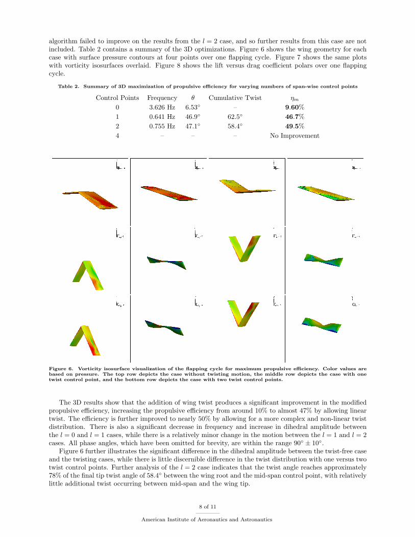
algorithm failed to improve on the results from the l = 2 case, and so further results from this case are notincluded. Table 2 contains a summary of the 3D optimizations. Figure 6 shows the wing geometry for eachcase with surface pressure contours at four points over one apping cycle. Figure 7 shows the same plotswith vorticity isosurfaces overlaid. Figure 8 shows the lift versus drag coe�cient polars over one appingcycle.
Table 2. Summary of 3D maximization of propulsive e�ciency for varying numbers of span-wise control points
Control Points Frequency � Cumulative Twist �m
0 3.626 Hz 6:53� { 9:60%1 0.641 Hz 46:9� 62:5� 46:7%2 0.755 Hz 47:1� 58:4� 49:5%4 { { { No Improvement
Figure 6. Vorticity isosurface visualization of the apping cycle for maximum propulsive e�ciency. Color values arebased on pressure. The top row depicts the case without twisting motion, the middle row depicts the case with onetwist control point, and the bottom row depicts the case with two twist control points.
The 3D results show that the addition of wing twist produces a signi�cant improvement in the modi�edpropulsive e�ciency, increasing the propulsive e�ciency from around 10% to almost 47% by allowing lineartwist. The e�ciency is further improved to nearly 50% by allowing for a more complex and non-linear twistdistribution. There is also a signi�cant decrease in frequency and increase in dihedral amplitude betweenthe l = 0 and l = 1 cases, while there is a relatively minor change in the motion between the l = 1 and l = 2cases. All phase angles, which have been omitted for brevity, are within the range 90� � 10�.
Figure 6 further illustrates the signi�cant di�erence in the dihedral amplitude between the twist-free caseand the twisting cases, while there is little discernible di�erence in the twist distribution with one versus twotwist control points. Further analysis of the l = 2 case indicates that the twist angle reaches approximately78% of the �nal tip twist angle of 58:4� between the wing root and the mid-span control point, with relativelylittle additional twist occurring between mid-span and the wing tip.
8 of 11
American Institute of Aeronautics and Astronautics
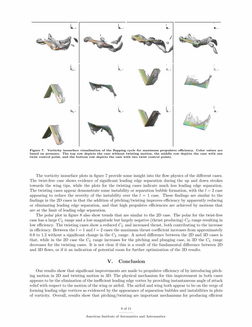
Figure 7. Vorticity isosurface visualization of the apping cycle for maximum propulsive e�ciency. Color values arebased on pressure. The top row depicts the case without twisting motion, the middle row depicts the case with onetwist control point, and the bottom row depicts the case with two twist control points.
The vorticity isosurface plots in �gure 7 provide some insight into the ow physics of the di�erent cases.The twist-free case shows evidence of signi�cant leading edge separation during the up and down strokestowards the wing tips, while the plots for the twisting cases indicate much less leading edge separation.The twisting cases appear demonstrate some instability or separation bubble formation, with the l = 2 caseappearing to reduce the severity of the instability over the l = 1 case. These �ndings are similar to the�ndings in the 2D cases in that the addition of pitching/twisting improves e�ciency by apparently reducingor eliminating leading edge separation, and that high propulsive e�ciencies are achieved by motions thatare at the limit of leading edge separation.
The polar plot in �gure 8 also show trends that are similar to the 2D case. The polar for the twist-freecase has a large CL range and a low-magnitude but largely negative (thrust producing) CD range resulting inlow e�ciency. The twisting cases show a reduced CL and increased thrust, both contributing to the increasein e�ciency. Between the l = 1 and l = 2 cases the maximum thrust coe�cient increases from approximately0.8 to 1.2 without a signi�cant change in the CL range. A noted di�erence between the 2D and 3D cases isthat, while in the 2D case the CL range increases for the pitching and plunging case, in 3D the CL rangedecreases for the twisting cases. It is not clear if this is a result of the fundamental di�erence between 2Dand 3D ows, or if it an indication of potential room for further optimization of the 2D results.
V. Conclusion
Our results show that signi�cant improvements are made to propulsive e�ciency of by introducing pitch-ing motion in 2D and twisting motion in 3D. The physical mechanism for this improvement in both casesappears to be the elimination of the ine�cient leading edge vortex by providing instantaneous angle of attackrelief with respect to the motion of the wing or airfoil. The airfoil and wing both appear to be on the verge offorming leading edge vortices as evidenced by the appearance of separation bubbles and instabilities in plotsof vorticity. Overall, results show that pitching/twisting are important mechanisms for producing e�cient
9 of 11
American Institute of Aeronautics and Astronautics
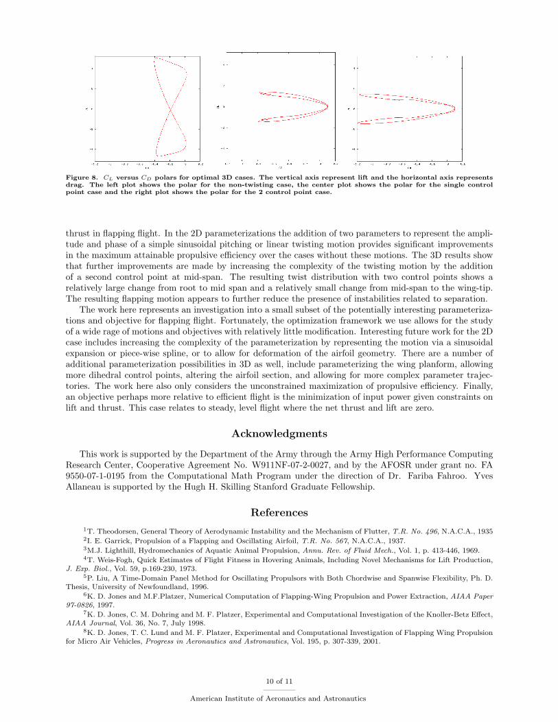
Figure 8. CL versus CD polars for optimal 3D cases. The vertical axis represent lift and the horizontal axis representsdrag. The left plot shows the polar for the non-twisting case, the center plot shows the polar for the single controlpoint case and the right plot shows the polar for the 2 control point case.
thrust in apping ight. In the 2D parameterizations the addition of two parameters to represent the ampli-tude and phase of a simple sinusoidal pitching or linear twisting motion provides signi�cant improvementsin the maximum attainable propulsive e�ciency over the cases without these motions. The 3D results showthat further improvements are made by increasing the complexity of the twisting motion by the additionof a second control point at mid-span. The resulting twist distribution with two control points shows arelatively large change from root to mid span and a relatively small change from mid-span to the wing-tip.The resulting apping motion appears to further reduce the presence of instabilities related to separation.
The work here represents an investigation into a small subset of the potentially interesting parameteriza-tions and objective for apping ight. Fortunately, the optimization framework we use allows for the studyof a wide rage of motions and objectives with relatively little modi�cation. Interesting future work for the 2Dcase includes increasing the complexity of the parameterization by representing the motion via a sinusoidalexpansion or piece-wise spline, or to allow for deformation of the airfoil geometry. There are a number ofadditional parameterization possibilities in 3D as well, include parameterizing the wing planform, allowingmore dihedral control points, altering the airfoil section, and allowing for more complex parameter trajec-tories. The work here also only considers the unconstrained maximization of propulsive e�ciency. Finally,an objective perhaps more relative to e�cient ight is the minimization of input power given constraints onlift and thrust. This case relates to steady, level ight where the net thrust and lift are zero.
Acknowledgments
This work is supported by the Department of the Army through the Army High Performance ComputingResearch Center, Cooperative Agreement No. W911NF-07-2-0027, and by the AFOSR under grant no. FA9550-07-1-0195 from the Computational Math Program under the direction of Dr. Fariba Fahroo. YvesAllaneau is supported by the Hugh H. Skilling Stanford Graduate Fellowship.
References
1T. Theodorsen, General Theory of Aerodynamic Instability and the Mechanism of Flutter, T.R. No. 496, N.A.C.A., 19352I. E. Garrick, Propulsion of a Flapping and Oscillating Airfoil, T.R. No. 567, N.A.C.A., 1937.3M.J. Lighthill, Hydromechanics of Aquatic Animal Propulsion, Annu. Rev. of Fluid Mech., Vol. 1, p. 413-446, 1969.4T. Weis-Fogh, Quick Estimates of Flight Fitness in Hovering Animals, Including Novel Mechanisms for Lift Production,
J. Exp. Biol., Vol. 59, p.169-230, 1973.5P. Liu, A Time-Domain Panel Method for Oscillating Propulsors with Both Chordwise and Spanwise Flexibility, Ph. D.
Thesis, University of Newfoundland, 1996.6K. D. Jones and M.F.Platzer, Numerical Computation of Flapping-Wing Propulsion and Power Extraction, AIAA Paper
97-0826, 1997.7K. D. Jones, C. M. Dohring and M. F. Platzer, Experimental and Computational Investigation of the Knoller-Betz E�ect,
AIAA Journal, Vol. 36, No. 7, July 1998.8K. D. Jones, T. C. Lund and M. F. Platzer, Experimental and Computational Investigation of Flapping Wing Propulsion
for Micro Air Vehicles, Progress in Aeronautics and Astronautics, Vol. 195, p. 307-339, 2001.
10 of 11
American Institute of Aeronautics and Astronautics
9P. -O. Persson, D. J. Willis and J. Peraire, The Numerical Simulation of Flapping Wings at Low Reynolds Numbers,AIAA Paper 2010-724
10K. Ou, P. Castonguay and A. Jameson, 3D Wing Simulation with High-Order Spectral Di�erence Method on DeformableMesh, AIAA Paper, Orlando, 2011.
11W. Shyy, Y. Lian, J. Tang, H. Liu, P. Trizila, B. Stanford, L. Bernal, C. Cesnik, P. Friedmann, P. Ifju, ComputationalAerodynamics of Low Reynolds Number Plunging, Pitching and Flexible Wings for MAV Applications, AIAA Paper 2008-523
12R. T. Jones, Wing Flapping with Minimum Energy, NASA TMJ81174, 1980.13K. C. Hall and S. R. Hall, Minimum Induced Power requirements for Flapping Flight, J. Fluid. Mech., Vol 323, p. 285-315,
1996.14M. Hamdaoui, J.-B. Mouret, S. Doncieux and P. Sagaut, Optimization of Kinematics for Birds and UAVs using Evolu-
tionary Algorithms, Proceedings of the World Academy of Science, Engineering and Technology, Vol. 30, July 2008.15K. Ito, Optimization of Flapping Wing Motion, ICAS 2002 Congress, 2002.16K. A. Strang, E�cient Flapping Flight of Pterosaurs, Ph. D. Thesis, Stanford University, 2009.17M. Milano and M. Gharib, Uncovering the Physics of Flapping Flat Plates with Arti�cial Evolution, J. Fluid Mech., Vol.
534, p. 403-409, 2005.18I. H. Tuncer and M. Kaya, Optimization of Flapping Airfoils for Maximum Thrust and Propulsive E�ciency, Acta
Polytechnica, Vol 44, No. 1, 2004.19D. J. Willis, P. -O. Persson, E. R. Israeli, J. Peraire, S. M. Swartz, K. S. Breuer, Multi�delity Approaches for the
Computational Analysis and Design of E�ective Flapping Wing Vehicles, AIAA Paper 2008-518, 2008.20A. Jameson, The Construction of Discretely Conservative Finite Volume Schemes that Also Globally Conserve Energy
or Entropy, Journal of Scienti�c Computing, Vol. 34-2, p. 152-187, 200821A. Jameson, Formulation of Kinetic Energy Preserving Conservative Schemes for Gas Dynamics and Direct Numerical
Simulation of One-Dimensional Viscous Compressible Flow in a Shock Tube Using Entropy and Kinetic Energy PreservingSchemes, Journal of Scienti�c Computing, Vol. 34-2, p. 188-208, 2008
22Y. Allaneau and A. Jameson, Direct Numerical Simulations of Plunging Airfoils, AIAA Paper 2010-728, January 2010.23Y. Allaneau, M. Culbreth and A. Jameson, A Computational Framework for Low Reynolds Number 3D Flapping Wings
Simulations, AIAA Paper, Hawaii, 2011.24C. W. Shu, Total Variation Diminishing Time Discretizations, SIAM Journal on Scienti�c and Statistical Computing,
Vol. 9, p. 1073-108425P. E. Gill, W. Murray, and M. A. Saunders, SNOPT: An SQP Algorithm for Large-Scale Constrained Optimization,
SIAM Rev. Vol. 47-1, 99-131, 2005
11 of 11
American Institute of Aeronautics and Astronautics