hfc-227ea agent storage containers description · hfc-227ea agent storage containers description...
TRANSCRIPT
HFC-227EA AGENT STORAGE CONTAINERS
DESCRIPTION
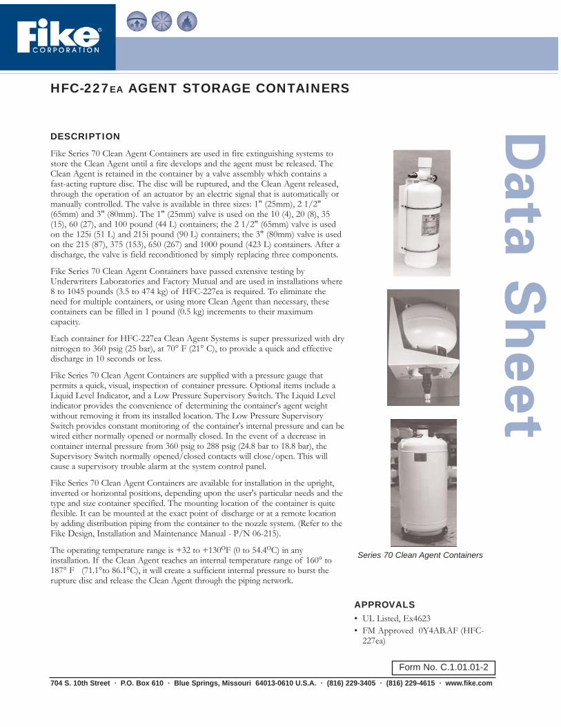
Fike Series 70 Clean Agent Containers are used in fire extinguishing systems tostore the Clean Agent until a fire develops and the agent must be released. TheClean Agent is retained in the container by a valve assembly which contains afast-acting rupture disc. The disc will be ruptured, and the Clean Agent released,through the operation of an actuator by an electric signal that is automatically ormanually controlled. The valve is available in three sizes: 1" (25mm), 2 1/2"(65mm) and 3" (80mm). The 1" (25mm) valve is used on the 10 (4), 20 (8), 35(15), 60 (27), and 100 pound (44 L) containers; the 2 1/2" (65mm) valve is usedon the 125i (51 L) and 215i pound (90 L) containers; the 3" (80mm) valve is usedon the 215 (87), 375 (153), 650 (267) and 1000 pound (423 L) containers. After adischarge, the valve is field reconditioned by simply replacing three components.
Fike Series 70 Clean Agent Containers have passed extensive testing byUnderwriters Laboratories and Factory Mutual and are used in installations where8 to 1045 pounds (3.5 to 474 kg) of HFC-227ea is required. To eliminate theneed for multiple containers, or using more Clean Agent than necessary, thesecontainers can be filled in 1 pound (0.5 kg) increments to their maximumcapacity.
Each container for HFC-227ea Clean Agent Systems is super pressurized with drynitrogen to 360 psig (25 bar), at 70° F (21° C), to provide a quick and effectivedischarge in 10 seconds or less.
Fike Series 70 Clean Agent Containers are supplied with a pressure gauge thatpermits a quick, visual, inspection of container pressure. Optional items include aLiquid Level Indicator, and a Low Pressure Supervisory Switch. The Liquid Levelindicator provides the convenience of determining the container's agent weightwithout removing it from its installed location. The Low Pressure SupervisorySwitch provides constant monitoring of the container's internal pressure and can bewired either normally opened or normally closed. In the event of a decrease incontainer internal pressure from 360 psig to 288 psig (24.8 bar to 18.8 bar), theSupervisory Switch normally opened/closed contacts will close/open. This willcause a supervisory trouble alarm at the system control panel.
Fike Series 70 Clean Agent Containers are available for installation in the upright,inverted or horizontal positions, depending upon the user's particular needs and thetype and size container specified. The mounting location of the container is quiteflexible. It can be mounted at the exact point of discharge or at a remote locationby adding distribution piping from the container to the nozzle system. (Refer to theFike Design, Installation and Maintenance Manual - P/N 06-215).
The operating temperature range is +32 to +130oF (0 to 54.4oC) in anyinstallation. If the Clean Agent reaches an internal temperature range of 160° to187° F (71.1°to 86.1°C), it will create a sufficient internal pressure to burst therupture disc and release the Clean Agent through the piping network.
704 S. 10th Street · P.O. Box 610 · Blue Springs, Missouri 64013-0610 U.S.A. · (816) 229-3405 · (816) 229-4615 · www.fike.com
APPROVALS• UL Listed, Ex4623• FM Approved 0Y4AB.AF (HFC-
227ea)
Series 70 Clean Agent Containers
Form No. C.1.01.01-2

"B"
"A"
Liquid Level Boss
3" (80mm) Outlet1/2" (15mm)
ElectricalConnection
"B"
"A"
Liquid Level Boss
1" (25mm) Outlet1/2" (15mm)
ElectricalConnection
"A"
"B"
Liquid Level Boss
2-1/2" (65mm) Outlet1/2" (15mm)Electrical
Connection
DESCRIPTION (cont.)
ReliabilityFike Series 70 Clean Agent Containers are manufactured in strict accordance withDepartment of Transportation (DOT) regulations. The Fike Series 70 Clean AgentContainers have successfully passed testing by Factory Mutual and UnderwritersLaboratories, Inc. Before leaving the factory, each container must pass extensive leakagetesting, and pressure testing to 1000 psig (69 bar). The containers are constructed fromcarbon steel alloys and painted with a durable, baked enamel finish.
InstallationFike Series 70 Clean Agent Containers are supplied with a mounting bracket that isdesigned to provide the most effective and versatile installation for that particularcontainer. The 10, 20 and 35 pound (4, 8 and 15 L) container brackets employ two U-bolts for securing the container to the bracket. The 60 pound (27 L) container is securedusing two quick connecting, over-center handle clamps. The 125i and 215i pound (51 and90 L) containers utilize an "L" shaped bracket for direct wall mounting or, with anoptional floor mounting kit, can be mounted on a floor in the "valve down" position. The100 pound (44 L) and 215 pound (87 L) through 1000 pound (423 L) containers aresupplied with one or two U-shaped mounting brackets, depending upon container size,for mounting to a wall or other secure surface.
Container Sizes and Dimensions: U.S. Standard and Metric
Size-lb 10 20 35 60 100 125i 215i 215 375 650 100
A(in) 7 7.25 7.25 10.75 10.75 20.00 24.00 20.00 20.00 24.00 24.00
B(in) 14.12 21.50 32.50 28.00 38.75 20.25 23.75 28.87 42.50 48.75 70.00
Size-L 4 8 15 27 44 51 90 87 153 267 423
A(mm) 178 184 184 273 273 508 610 508 508 610 610
B(mm) 359 546 826 711 984 515 605 733 1080 1237 1778
U.S. SIZES & DIMENSIONS
METRIC SIZES & DIMENSIONS

AVAILABLE MODELS AND SPECIFICATIONS
FIKE P/N SIZE (LB) VALVE (IN) EMPTY WT(LB)
HFC-227eaAGENT FILL
RANGE (LBS)
VALVEPOSITION
DOTREGULATION
70-108 10 1 15 8-10 horiz or upright 4BW50070-098 20 1 21 12-21 horiz or upright 4BW50070-089 35 1 32 22-38 horiz or upright 4BW50070-152 60 1 44 39-68 horiz or upright 4BW50070-153 100 1 61 63-108 upright 4BW50070-041 125i 2 ½ 180 73-126 inverted 4BA50070-077 215i 2 ½ 225 128-223 inverted 4BA50070-154 215 3 150 124-216 upright 4BW50070-155 375 3 218 217-378 upright 4BW50070-156 650 3 350 378-660 upright 4BW50070-157 1000 3 515 598-1045 upright 4BW500
FIKE P/N SIZE (L) VALVE(MM)
EMPTY WT(KG)
HFC-227eaAGENT FILLRANGE (KG)
VALVEPOSITION
DOTREGULATION
70-108 4 25 7 4.0-4.5 horiz or upright 4BW50070-098 8 25 10 5.5-9.5 horiz or upright 4BW50070-089 15 25 15 10.0-17.0 horiz or upright 4BW50070-152 27 25 20 18.0-30.5 horiz or upright 4BW50070-153 44 25 28 28.5-48.5 upright 4BW50070-041 51 65 82 33.5-57.0 inverted 4BA50070-077 90 65 102 58.5-101.0 inverted 4BA50070-154 87 80 68 56.5-98.0 upright 4BW50070-155 153 80 99 98.5-171.5 upright 4BW50070-156 267 80 159 171.5-299.0 upright 4BW50070-157 423 80 234 271.5-474.0 upright 4BW500
CLEAN AGENT STORAGE CONTAINER DATA - U.S. STANDARD
CLEAN AGENT STORAGE CONTAINER DATA - METRIC

Copyright © Fike Corporation All Rights Reserved.Form No. C.1.01.01-2 March, 2005 Specifications are subject to change without notice.
ARCHITECT AND ENGINEERING SPECIFICATIONSThe Clean Agent shall be stored in Fike Series 70 Clean Agent Storage Containers. The containers shall be capable of beingfilled, in one-pound (0.5kg) increments, to their listed maximum capacity. The Clean Agent container shall be activated by asignal from the control panel which is processed by the Agent Release Module. This module shall store the power requiredto operate the actuator. The valve shall contain a scored, non-fragmenting, rupture disc to provide an immediate, totaldischarge of all the agent. HFC-227ea Clean Agent is stored in the container as a liquid, having a natural vapor pressure of66 psig at 77°F (5 barg at 25°C). To aid in discharge, the container shall be super-pressurized to 360 psig at 70°F (25 bar at21.1°C) with dry nitrogen. Agent discharge shall be completed in 10 seconds or less.
Clean Agent Storage Containers shall be actuated by an electrical signal that is automatically or manually controlled. Normaloperating temperature shall be +32 to +130°F (0 to 54.4°C) in any installation.
Clean Agent Storage Containers shall be equipped with a pressure gauge to display internal pressure. This gauge shall be anintegral part of the container and color coded for fast referencing of pressure readings. A Low Pressure Supervisory Switchshall be made available as an option. A decrease in internal container pressure from 360 psig to 288 psig (24.8 bar to 18.8bar) shall cause the normally opened/closed Supervisory Switch contacts to close/open, indicating a trouble or supervisorycondition at the control panel.
Clean Agent Storage Containers shall be fastened to a wall, or other secure surface, using a mounting bracket that isdesigned for the most effective and versatile installation of each container.
HFC-227EA PRE-ENGINEERED NOZZLES
DESCRIPTION
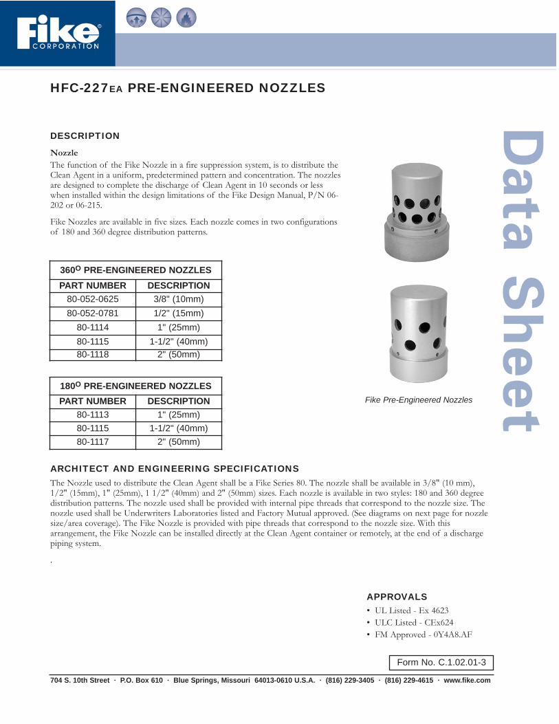
NozzleThe function of the Fike Nozzle in a fire suppression system, is to distribute theClean Agent in a uniform, predetermined pattern and concentration. The nozzlesare designed to complete the discharge of Clean Agent in 10 seconds or lesswhen installed within the design limitations of the Fike Design Manual, P/N 06-202 or 06-215.
Fike Nozzles are available in five sizes. Each nozzle comes in two configurationsof 180 and 360 degree distribution patterns.
704 S. 10th Street · P.O. Box 610 · Blue Springs, Missouri 64013-0610 U.S.A. · (816) 229-3405 · (816) 229-4615 · www.fike.com
Fike Pre-Engineered Nozzles
360O PRE-ENGINEERED NOZZLESPART NUMBER DESCRIPTION
80-052-0625 3/8" (10mm) 80-052-0781 1/2" (15mm)
80-1114 1" (25mm)80-1115 1-1/2" (40mm)80-1118 2" (50mm)
180O PRE-ENGINEERED NOZZLESPART NUMBER DESCRIPTION
80-1113 1" (25mm)80-1115 1-1/2" (40mm)80-1117 2" (50mm)
Form No. C.1.02.01-3
ARCHITECT AND ENGINEERING SPECIFICATIONSThe Nozzle used to distribute the Clean Agent shall be a Fike Series 80. The nozzle shall be available in 3/8" (10 mm),1/2" (15mm), 1" (25mm), 1 1/2" (40mm) and 2" (50mm) sizes. Each nozzle is available in two styles: 180 and 360 degreedistribution patterns. The nozzle used shall be provided with internal pipe threads that correspond to the nozzle size. Thenozzle used shall be Underwriters Laboratories listed and Factory Mutual approved. (See diagrams on next page for nozzlesize/area coverage). The Fike Nozzle is provided with pipe threads that correspond to the nozzle size. With thisarrangement, the Fike Nozzle can be installed directly at the Clean Agent container or remotely, at the end of a dischargepiping system.
.
APPROVALS• UL Listed - Ex 4623• ULC Listed - CEx624• FM Approved - 0Y4A8.AF

Copyright © Fike Corporation All Rights Reserved.Form No. C.1.02.01-3 March, 2005 Specifications are subject to change without notice.
Nozzle Size and Area Coverage
NOTES:a. An allowable area of coverage includes any area where the maximum coverage from the nozzle ("R" dimension) is not exceeded.b. Nozzles should be located on center line of hazard area.c. When working with ceiling heights exceeding the values tabulated above, the hazard volume must be broken down into vertically stacked hazard
volumes, with heights less than the maximums shown in the table. It is imperative that unusual applications of this nature be handled by experiencedpeople in the field, and in most cases, operational tests should be performed before the system is put into service.
d. Dimensions and nozzle data shown are taken from the UL listed and FM approved Design, Installation & Maintenance Manual - P/N 06-202 or 06-215.
e. 180 and 360 degree nozzles may be placed a maximum of 1 foot (30.5cm) down from the ceiling, and 180 degree nozzles may be placed amaximum of 1 foot (30.5cm) from the wall.
Nozzle Area Coverage
Nozzle Type Radius “R”Dimension (English)
Radius “R”Dimension (Metric)
Ceiling HeightRange (English)
Ceiling HeightRange (Metric)
180o 45'-8" 13.92m 12 in. to 16 ft. 0.3 to 4.88m
360o 29'-8" 9.04m 12 in. to 16 ft. 0.3 to 4.88m
R
R
180° Nozzle 360° Nozzle

HFC-227EA CONTAINER ACCESSORIES
DESCRIPTION
Reload Kit HFC-227ea85-023 - 1" (25mm) Valve and 85-024 - 2 1/2" (65mm) ValveThe Series 85 Reload Kits are designed to facilitate field reconditioning of thecomplete line of Fike Clean Agent Containers. The 1" (25mm) Reload Kit willservice the 10, 20, 35, 60 and 100 lb. (4, 8, 15, 27, 44 liter) Fike Containers. The2 1/2" (65mm) kit will service the Fike 125i and 215i lb. (51 & 90 liter)Containers. Generally, each kit consists of a rupture disc, a gas cartridge actuatorand actuator housing, pressure gauge, replacement core for the fill valve, O-ring,and a teflon ring.
Reload Kit HFC-227ea 85-025 - 3" (80mm) ValveThe 3" (80mm) Reload Kit provides field reconditioning of the 215, 375, 650,and 1000 lb. (87, 153, 267, 423 liter) Containers. Each kit consists of a 3" (80mm)rupture disc valve assembly, gas cartridge actuator, "O"-rings, pressure gauge andreplacement core for the fill valve.
Low Pressure Switch70-1121 - All Containers Over 10 lb. (4 liters) 70-1650 - 10 lb. Container Only These devices monitor the pressure within the Clean Agent Container. Shouldloss of Agent or Nitrogen occur, the Pressure Switch's normal contacts willtransfer indicating a low pressure condition.
Specifications• Temperature Limits: 32° to 120° F (0-48.9°C)• Enclosure Classification: NEMA 4• Contact Rating: Single pole, double throw; 5 amps resistive, 3 amps
inductive @ 30VDC
• Body Material: Aluminum with irridite finish• Weight: 6.5 ounces• Pressure Connection: 1/8” NPT (6mm)• Electrical Connection: 1/2” NPT (15mm)• Pressure Setting: 288 psig (20 bar)(decreasing)
704 S. 10th Street · P.O. Box 610 · Blue Springs, Missouri 64013-0610 U.S.A. · (816) 229-3405 · (816) 229-4615 · www.fike.com
APPROVALS• UL Listed - Ex4623• FM Approved - 0Y4A8.AF
Reload Kit (1” and 2 1/2”)
Reload Kit (3”)
Pressure Switch
Form No. C.1.03.01-2
Copyright © Fike Corporation All Rights Reserved.Form # C.1.03.01-2 March, 2005 Specifications are subject to change without notice.
Victaulic Nipple and Coupling
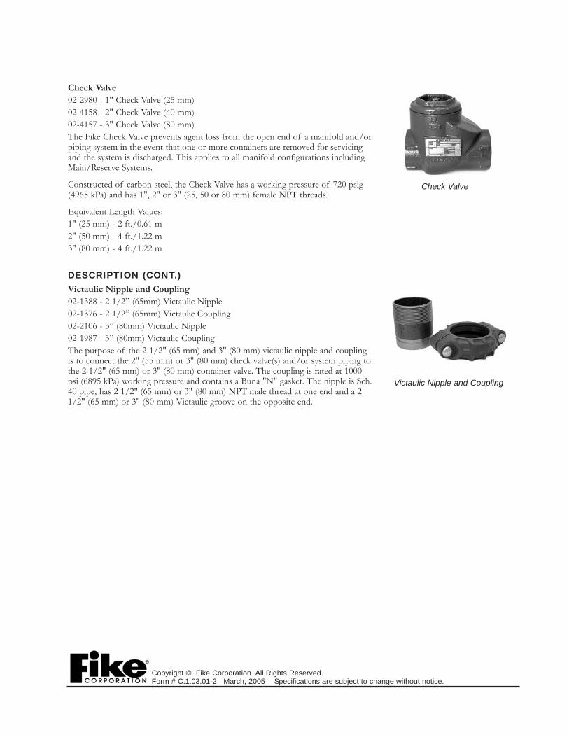
Check Valve02-2980 - 1" Check Valve (25 mm) 02-4158 - 2" Check Valve (40 mm) 02-4157 - 3" Check Valve (80 mm)The Fike Check Valve prevents agent loss from the open end of a manifold and/orpiping system in the event that one or more containers are removed for servicingand the system is discharged. This applies to all manifold configurations includingMain/Reserve Systems.
Constructed of carbon steel, the Check Valve has a working pressure of 720 psig(4965 kPa) and has 1", 2" or 3" (25, 50 or 80 mm) female NPT threads.
Equivalent Length Values:1" (25 mm) - 2 ft./0.61 m2" (50 mm) - 4 ft./1.22 m3" (80 mm) - 4 ft./1.22 m
DESCRIPTION (CONT.)Victaulic Nipple and Coupling02-1388 - 2 1/2” (65mm) Victaulic Nipple02-1376 - 2 1/2” (65mm) Victaulic Coupling02-2106 - 3” (80mm) Victaulic Nipple02-1987 - 3” (80mm) Victaulic Coupling The purpose of the 2 1/2" (65 mm) and 3" (80 mm) victaulic nipple and couplingis to connect the 2" (55 mm) or 3" (80 mm) check valve(s) and/or system piping tothe 2 1/2" (65 mm) or 3" (80 mm) container valve. The coupling is rated at 1000psi (6895 kPa) working pressure and contains a Buna "N" gasket. The nipple is Sch.40 pipe, has 2 1/2" (65 mm) or 3" (80 mm) NPT male thread at one end and a 21/2" (65 mm) or 3" (80 mm) Victaulic groove on the opposite end.
Check Valve

AGENT RELEASE MODULE
DESCRIPTIONThe Agent Release Module (ARM III), Fike P/N 10-1832, in conjunction with aFike Control Panel, allows the electrical actuators used with Fike Clean Agentcontainers to be wired in parallel. This configuration substantially increases theoverall reliability of the Clean Agent releasing circuit. With series-wired actuatorcircuits, a problem in a single actuator will incapacitate the entire system. Utilizingparallel-wired actuators, that same incident would incapacitate only that individualClean Agent container; all others would still be active.
The Agent Release Module (ARM III) is compatible with either Class A or ClassB wiring. When an ARM III is used in a Class A wiring configuration, theresulting system is the most reliable available for today's Fire Protection.
InstallationThe Fike Agent Release Module (ARM III) is mounted in the lower right corner ofa 4 11/16" (11.9 cm) square box which connects to the actuator boss on the CleanAgent container. The ARM III is a solid-state circuit board and contains a terminalstrip for the connections of field wiring and actuator leads. The module is alsoequipped with a polarity diode that illuminates if the field wiring has been installedwith reversed polarity. Special care should be taken to assure proper polarity.
ARCHITECT AND ENGINEERING SPECIFICATIONSEach Clean Agent container shall be provided with a Fike P/N 10-1832 AgentRelease Module (ARM III) to allow all electrical actuators to be connected inparallel. Series-wired actuators are not acceptable. The ARM III shall be locatedat each container and shall be securely mounted in the lower right hand corner ofa 4 11/16" (11.9cm) square electrical box, with cover. All wiring to the CleanAgent container and the actuator leads shall connect to a terminal strip located onthe ARM III.
704 S. 10th Street · P.O. Box 610 · Blue Springs, Missouri 64013-0610 U.S.A. · (816) 229-3405 · (816) 229-4615 · www.fike.com
APPROVALS• UL Listed - S3217• FM Approved
• Cheetah: 0B4A6.AY • Rhino: 0Y4A4.AY• SHP Pro: 0Z8A0.AY
Fike Agent Release Module
Form No. C.1.04.01-2
10-1832 ARM
1.5K EOL
+ - R B Y G - + 10-1832 ARM
+ - R B Y G - +TO CONTROL PANEL
Maximum of 6 ARMs
WIRING DIAGRAM

Copyright © Fike Corporation All Rights Reserved.Form No. C.1.04.01-2 March, 2005 Specifications are subject to change without notice.
This page intentionally left blank.

HFC-227EA LIQUID LEVEL INDICATOR
DESCRIPTIONThe Fike 70-1353 series Liquid Level Indicator is asimple manually operated device which provides ameans to determine the Clean Agent liquid level invertically mounted agent storage containers. Once theliquid level is determined, it can then be convertedinto pounds (kilograms) of Clean Agent present in theagent storage container. (Refer to Fike HFC-227eaInstruction Manual for Liquid Level Indicator (LLi),P/N 06-107.)
OperationA magnet equipped float moves with the liquid level along the unit stem. Levelreadout is obtained by simply removing the protective cap and pulling out acalibrated tape until magnetic interlock with the float is felt. With the tape in thisposition, the reading is obtained at the point where the tape emerges from theunit housing.
When the liquid level is determined, the reading is then located on a chart and thecorresponding Clean Agent weight is read. Accurate readings can be obtainedover a +40 to +90oF (+4.4 to +32.2oC) temperature range.
Features• Reduced maintenance time - the weight of the agent in storage containers can
be determined in a fraction of the time it would take to remove and weighthem.
• Continuous fire protection - use of the liquid level indicator does not requireshutting down the Clean Agent System, thus affording uninterrupted fireprotection.
• Field installation capability - the indicator can easily be installed in the fieldusing a single wrench, as long as the container is empty and is equipped with amounting boss.
• Compact - when not in use, the unit requires no more space than that requiredby the container.
• Flexibility - the flexible tape design allows the unit to be used in tight spacesthat would otherwise hinder the use of a rigid indicator "stick".
• Availability - units are available for Fike container sizes of 100 lb. (44 liter)through 1000 lb. (423 liter) in both the modular and central storage typedesigns.
ConstructionThe Fike 70-1353 series Liquid Level Indicator housing and stem assembly isconstructed of brass. The flexible indicator tape is constructed of steel with ayellow mylar coating. The indicator tape is calibrated in inches and centimeters.
The unit housing provides straight mounting threads with a static O-ring seal.The float is constructed of a special ECCO material for high pressure service.The cellular construction of the ECCO material allows the float to be solid and isnot susceptible to water-logging, as hollow floats are if they develop a leak. Theunit is provided with a plastic protective cap.
704 S. 10th Street · P.O. Box 610 · Blue Springs, Missouri 64013-0610 U.S.A. · (816) 229-3405 · (816) 229-4615 · www.fike.com
APPROVALS• UL Ex4623• FM 3002238• USCG 162.161/2/0
Liquid Level Indicator
Form No. C.1.05.01-2
MAGNETICFLOAT
LIQUID LEVEL
UNIT STEM
LLi BOSS
READ HERE
INDICATOR TAPE

Copyright © Fike Corporation All Rights Reserved.Form No. C.1.05.01-2 March, 2005 Specifications are subject to change without notice.
ARCHITECT AND ENGINEERING SPECIFICATIONSAgent storage containers of 100 lb. (44 liter) capacity or more shall be provided with a reliable means, other than weighing,of determining the agent weight within the storage container during normal routine service.
The device used shall be a Fike 70-1353-xx series Liquid Level Indicator and shall not require any additional space when thecontainer is installed.
Use of the indicator shall not require the Clean Agent System to be shut down, thus allowing uninterrupted fire protectionduring service intervals. Level indicators which are not factory installed shall be capable of being retrofitted in the field,with a single standard wrench, when the container is removed for recharge.
The level indicator tape shall be flexible to allow use in confined spaces. The unit housing shall be constructed of brasswith straight mounting threads and a static O-ring seal. The float shall be of solid construction to eliminate the possibilityof water logging to which hollow floats are susceptible. The float shall be equipped with a magnet which provides for apositive feel when the magnetic interlock is reached between the float and indicating tape.
When the level reading is obtained, the agent weight can be determined through the use of the chart or graph found in theLiquid Level Indicator Manual (P/N: 06-107). Accurate readings shall be capable of being obtained over a +40oF (+4.4oC)to 90oF (+32.2oC) temperature range.
AVAILABLE MODELS
INDICATOR P/N DIMENSION “L” CONTAINER SIZE CONTAINER P/N70-1353-22 22” (381 mm) 100 lb (44 liter) 70-15370-1353-11 11” (278 mm) 125i lb (51 liter) 70-04170-1353-15 15” (381 mm) 215 lb (87 liter) 70-154/S70-15470-1353-15 15” (381 mm) 215i lb (90 liter) 70-07770-1353-24 24” (610 mm) 375 lb (153 liter) 70-155 / S70-15570-1353-38 38” (965 mm) 650 lb “short” (267 liter “short”) 70-156 / S70-15670-1353-44 44” (1118 mm) 1000 lb (423 liter) 70-157 / S70-157
"L"
Float
InspectionTag
Cap
MeasuringTape

INTERFACE FIRING MODULE
DESCRIPTIONThe Interface Firing Module (IFM), Fike P/N 10-2136, is designed to allow anexisting control panel (approved for releasing service) to connect with a Fike CleanAgent system. The IFM is designed to operate from any of three different inputsignals from a listed control panel:Dry ContactA dry contact closure from a releasing circuit of a UL listed control panel willcause the IFM to enter the release state after the contacts are closed for a minimumof 1.1 seconds. When using dry contact output, all interface wiring must be in thesame room, within 20' of the panel, and in EMT or conduit.Polarity ReversalA polarity reversal circuit input (full reversal required) from a releasing circuit of aUL listed releasing control panel will cause the IFM to enter the release state afterthe polarity signal is reversed for at least 1.1 seconds. The listed releasing controlpanel supervises this circuit by allowing current to flow in one direction duringnormal operation and the reverse direction during the discharge state. When theIFM enters a trouble state, and immediately after power-up, the IFM opens thepolarity reversal circuit to signal a trouble condition at the control panel. Thepolarity reversal circuit can be wired for Class A or Class B operation. If wired forClass B operation, the EOL resistor must be installed across terminals 5 and 8.(Value determined by specific panel manufacturer.)Series FiringA series firing circuit from a compatible control panel which is UL listed forreleasing operation will cause the IFM to enter the release state after a sufficientlylarge current is passed through the circuit for at least 1.1 seconds. The panelsupervises the circuit by passing a lesser current level through the circuit. When theIFM enters a trouble state, and immediately after power-up, the IFM opens theseries firing circuit to signal a trouble condition on the control panel.The IFM is provided with an agent release circuit that is capable of connectingwith up to 20 Containers/Agent Release Modules (ARM III, Fike P/N 10-1832).It also supervises the integrity of the ARM circuit via Class B wiring by utilizing a1.5K ohm end-of-line device connected at the ARM.Upon activation of any one of the three types of inputs for a period of at least 1.1seconds, the IFM will energize the ARM III module(s), which in turn fires theactuator(s) to release the agent.The programmable output contact is a form A dry contact which can be set viaDIP switches for NO or NC operation. It also can be programmed for activationupon trouble or system alarm.The IFM is a power limited device which requires 24VDC input power from theexisting control panel.This module is designed to electrically isolate the input circuits from the outputcircuits to provide flexibility.
INSTALLATIONThe IFM is housed in an enclosure (4" x 3" x 1.5") (10.2 x 7.6 x 3.8 cm). Thishousing can be mounted in the control panel or a separate enclosure. An optionalmetal enclosure (10" x 6" x 2.5") (25.4 x 15.2 x 6.4 cm) with cover is offered; P/N10-2137.All wiring shall be with conductors approved for use in this application. The IFMincludes a removable terminal strip that can accommodate wiring sizes from 18 to14 AWG.
704 S. 10th Street · P.O. Box 610 · Blue Springs, Missouri 64013-0610 U.S.A. · (816) 229-3405 · (816) 229-4615 · www.fike.com
APPROVALS• UL/cUL Listed - S5566
Interface Firing Module
Form No. C.1.06.01-2

Copyright © Fike Corporation All Rights Reserved.Form No. C.1.06.01-2 March, 2005 Specifications are subject to change without notice.
STANDARD FEATURES/SPECIFICATIONS• Interfaces with existing approved releasing
control panels• Operates from any one of three different
inputs• Connects up to 20 Agent Release Modules
(ARMs)• Supervises the ARM circuit• Has test mode• Provides programmable output contact• Operating Voltage: 21-27 VDC• Current:
- Normal 45 mA Max.- Release 70 mA Max.- Trouble 150 mA Max.
Inputs• Polarity Reversal Input
- Maximum supervision voltage 30 VDC- Maximum release voltage 30 VDC- Minimum release voltage 12 VDC- Minimum release current required 5 mA
• Series Firing Input- Maximum supervision current 3.0 mA- Minimum release current 8.0 mA- Maximum release voltage 25.5 VDC- Minimum release voltage 20.7 VDC- Typical input impedance 1.5K ohm
• Dry Contact Input- Maximum Voltage across contact 30 VDC- Maximum Current through contact 50 mA
Outputs• Dry Contact Output Rating
- Maximum voltage 30 VDC- Maximum current 1.0 A
• ARM Circuit rating- Maximum Agent Release Modules 20
WIRING DIAGRAM
1
2
3
4
5
6
7
8
9
10
11
12
13
14
P/N 10-1832(ARM III)MODULERELEASE
AGENT
GCA
1.5K OHM2 WATT
UP TO 20 AGENT RELEASEMODULES PER CIRCUIT
EXTERNAL EOL
+
-
+
-
DRY CONTACT INPUT
AGENT RELEASE
POLARITY REVERSALCIRCUIT
SERIES FIRING CIRCUIT
DRY CONTACTOUTPUT
POWER INPUT
MODULE
UL Listed Control PanelApproved For Releasing Service
CIRCUIT
(POLARITY SHOWN INDISCHARGE CONDITION)
24VDC 0.2 AMP
Use one of three outputs Contact Monitor Circuit(for release or troublefeedback)
INTERFACE FIRING
24 VDC Power
-+
8
7
6
5
4
3
2
1
RED
BLU
YEL
GRN
AGENTRELEASEMODULE(ARM III)
P/N 10-1832
+-
1
2
3
4
5
6
7
8
+-
GRN
YEL
BLU
RED
GCA
-+
-
+

HFC-227EA
APPLICATION/DESCRIPTIONHFC-227ea provides superior fire protection in a wide range of applications fromsensitive electrical equipment to industrial applications using flammable liquids.HFC-227ea is ideal for applications where clean-up of other media presents aproblem, where weight versus suppression potential is a factor, where anelectrically non-conductive medium is needed and where people compatibility isan overriding factor. When environmental impact is a consideration, HFC-227eais particularly useful. It has zero ozone-depleting potential, low global warmingpotential and a short atmospheric lifetime. These characteristics make it suitablenot only for new installations using Fike’s total flooding systems, but also forHalon 1301 replacement applications.
HFC-227ea is an odorless, colorless, liquefied compressed gas. (See PhysicalProperties Table for additional information). It is stored as a liquid and dispensedinto the hazard as a colorless, electrically non-conductive vapor that is clear anddoes not obscure vision. It leaves no residue and has acceptable toxicity for use inoccupied spaces at design concentration. HFC-227ea extinguishes a fire by acombination of chemical and physical mechanisms. HFC-227ea does not displaceoxygen and therefore is safe for use in occupied spaces without fear of oxygendeprivation.
PerformanceHFC-227ea is an effective fire extinguishing agent that can be used on many typesof fires. It is effective for many surface fires, such as flammable liquids, and mostsolid combustible materials.
On a weight-of-agent basis, HFC-227ea is a very effective gaseous extinguishingagent. The HFC-227ea extinguishing concentration for normal Class Acombustibles is 6.25 - 7% by volume. The minimum design concentration fortotal flood applications should be in accordance with NFPA 2001.
SpecificationsHFC-227ea is manufactured to these specifications:• Mole%: 99.0 Minimum• Acidity, ppm by weight: 3.0 Maximum• Water content, % by weight: 0.001 Maximum• Non-volatile residues, gram/100mL: 0.05 Maximum
ToxicityThe toxicology of HFC-227ea compares favorably with other suppression agents.The LC50 of HFC-227ea is greater than 800,000 ppm. HFC-227ea has beenevaluated for cardiac sensitization via test protocols approved by the UnitedStates Environmental Protection Agency. Test results show that cardiac toleranceto HFC-227ea is higher than that of other suppression agents and is acceptablefor safe use in occupied spaces. HFC-227ea will decompose to form halogenacids when exposed to open flames. The formation of these acids is minimizedby using Fike early warning detection systems and proper system installation.When properly applied and installed, the generation of these by-products ofHFC-227ea should be minimal.
704 S. 10th Street · P.O. Box 610 · Blue Springs, Missouri 64013-0610 U.S.A. · (816) 229-3405 · (816) 229-4615 · www.fike.com
APPROVALSHFC-227ea complies with NFPAStandard 2001 - current edition. FikeHFC-227ea systems are UL listedand FM approved for Clean AgentFire Suppression Systems.• UL Listed Ex 4623• FM Approved 0Y4A8.AF• USCG 162.161/2/0
Form No. C.1.07.01-2

Copyright © Fike Corporation All Rights Reserved.Form No. C.1.07.01-2 March, 2005 Specifications are subject to change without notice.
PHYSICAL PROPERTIES• Chemical Name: Heptafluoropropane (CF3CHFCF3)• Molecular Weight: 170.03• Boiling Point @ 760 mm Hg: 2.55oF (-16.4oC)• Freezing Point : -204oF (-131.1oC)• Critical Temperature: 215oF (101.7oC)• Critical Pressure (psia): 422 psia (2912 kPa)• Critical Volume (ft3/lbm) (cc/mole): 0.0258 (274)• Critical Density (lbm/ft3): 38.8 (621 kg/m3)• Specific Heat, Liquid (BTU/lb-Fo) @ 77oF (25oC): 0.283 (1.184 kj/kg/oC)• Specific Heat, Vapor (BTU/lb-oF) @ constant pressure of 1 ATM @ 77oF (25oC):
0.1932 (0.808 kj/kg/oC)• Heat of Vaporization (BTU/lb) at Boiling Point: 57.0 (132.6 kj/kg)• Thermal Conductivity (BTU/h ftoF) of Liquid @ 77oF (25oC): 0.040 (0.069
w/moC)• Viscosity, Liquid (lb/ft hr) @ 77oF (25oC): 0.443 (0.184 centipoise)• Vapor Pressure (psia) @ 77oF (25oC): 66.4 (457.7 kPa)• Ozone Depletion Potential: 0• Estimated Atmospheric Lifetime (years): 31-42• LC50 (Rats; 4hrs - ppm): >800,000

HFC-227EA ENGINEERED NOZZLES
DESCRIPTIONThe function of the Fike Engineered Discharge Nozzle in a fire extinguishingsystem is to distribute the Clean Agent in a uniform, predetermined pattern andconcentration. The nozzles are designed to complete the discharge of CleanAgent in 10 seconds or less when installed within the design limitations of theFike Design, Installation and Maintenance Manual, P/N 06-202 or 06-215 and theFike Flow Calculation computer program.
Fike Engineered Discharge Nozzles are available in sizes of 3/8" (10mm)through 2" (50mm). Each nozzle is available in 180 and 360 degree dischargepatterns.
The Discharge Nozzle size refers to the size of Schedule 40 or 80 steel pipe towhich it can be connected. The nozzle discharge orifices are drilled perpendicularto the center line of the threads. The nozzles are mounted to allow the agent tobe discharged on a horizontal axis.
Nozzle orifices are available in a wide range of sizes to provide accurate CleanAgent flow results. All nozzles have been tested for their ability to discharge theClean Agent under extreme conditions.
Nozzle orifice drilling must be done at the Fike factory, or other UL listed nozzledrill station, only after "As-Built" calculations of the installed piping system(s)have been performed, using the Fike Flow Calculation computer program.
The Fike Discharge Nozzle used shall be Factory Mutual (FM) approved andUnderwriters Laboratories (UL) listed.
704 S. 10th Street · P.O. Box 610 · Blue Springs, Missouri 64013-0610 U.S.A. · (816) 229-3405 · (816) 229-0314 · www.fike.com
Fike Engineered Nozzles
APPROVALS• UL Listed - Ex4623• ULC Listed - CEx1136• FM Approved - 0Y4A8.AF
Form No. C.1.08.01-2
ARCHITECT AND ENGINEERING SPECIFICATIONSThe nozzle used to disperse Clean Agent shall be a Fike Series 80. The nozzle shall be available in 3/8" (10mm) thru 2"(50mm) sizes. Each size shall be available in both 180 and 360 degree dispersion patterns. The nozzle used shall have pipethreads that correspond to the nozzle size. All nozzles shall have an orifice size determined by a UL listed and FMapproved flow calculation program. All nozzle orifice drilling shall be performed by the manufacturer or a UL listed nozzledrilling facility.

Copyright © Fike Corporation All Rights Reserved.Form No. C.1.08.01-2 March, 2004 Specifications are subject to change without notice.
Nozzle Size and Area Coverage
NOTES:a. The maximum allowable area of coverage includes any area within the radius distance from the nozzle ("R" dimension) to the most extreme wall or
corner.b. Nozzles should be located on center line of hazard area.c. When working with ceiling heights exceeding the values tabulated above, the hazard volume must be broken down into vertically stacked hazard
volumes, with heights less than the maximums shown in the table.It is imperative that unusual applications of this nature be handled by experienced design engineers and, in most cases, operational tests should beperformed before the system is put into service.
d. Dimensions and nozzle data shown are taken from the UL listed and FM approved Design, Installation & Maintenance Manual - P/N 06-202 or 06-215.
e. 180 and 360 degree nozzles may be placed a maximum of 1 foot (30.5cm) down from the ceiling, and 180 degree nozzles may be placed amaximum of 1 foot (30.5cm) from the wall.
f. Nozzle threading is NPT.
NOZZLE SIZE 180O NOZZLE 360O NOZZLE(NPT) (mm) PART NUMBER PART NUMBER3/8" (10) 80-060 80-0521/2" (15) 80-061 80-0533/4" (20) 80-062 80-0541" (25) 80-063 80-055
1 1/4" (32) 80-064 80-0561 1/2" (40) 80-065 80-057
2" (50) 80-066 80-058
180° Nozzle 360° Nozzle
R
R
Nozzle Area Coverage
Nozzle Type “R”Dimension
Ceiling HeightRange
180 Degree 45’ - 8” (13.92) 1.0 to 16.0(0.3 to 4.9)
360 Degree 29’ - 8” (9.04) 1.0 to 16.0(0.3 to 4.9)

HFC-227EA INSTRUCTIONAL SIGNS
APPLICATIONInstructional signs must be supplied in order to provide a system in which thefunction of all devices is easy to understand. Fike offers several different standardsigns that comply with NFPA and other industry requirements. All signs aredurable plastic and backed with a strong adhesive for easy installation. Signs aretypically installed at all entrances (CAUTION - Room Protected By HFC-227ea)and near any device for which the extra explanation is helpful. Custom signs areavailable upon special request.
System “Release” Sign/Manual Release Station 02-10137The purpose of the System "Release" Sign is to identify the manual release stationas the place where the HFC-227ea System can be manually discharged. It alsominimizes the possibility of the manual station being mistaken for a fire alarmdevice. The sign is 4" x 2.25" x 1/16" (102 x 57 x 1.6mm) and is constructed ofred plastic with white lettering. The System "Release" Sign should normally belocated under each HFC-227ea manual release station for quick positiveidentification.
Upon Device Activation "Do Not Enter” Sign 02-10138The purpose of the System Discharge Sign is to explain the presence of an alarmin the event of a HFC-227ea System discharge. The sign is 9" x 6" x 1/16" (229 x152 x 1.6mm) and is constructed of white plastic with black lettering. The SystemDischarge Sign is located next to or under an audible or visual alarm outside ofthe protected space entrance(s). This sign, together with the alarm device(s) willalert personnel when HFC-227ea agent has discharged and allow them to takeappropriate actions.
Caution “Do Not Enter” Sign 02-10139The purpose of the Caution Sign is to alert personnel that the room is protectedby an HFC-227ea System and that all doors should be kept closed in the event offire. The sign is 10" x 13" x 1/16" (254 x 330 x 1.6mm) and constructed ofyellow plastic with black lettering. The Caution Sign should normally be locatedon the entrance door(s) leading into any room where HFC-227ea protection isbeing provided.
Upon Device Activation "Exit" Sign 02-10105The purpose of the System Discharge Sign is to explain the presence of an alarmin the event of an HFC-227ea System discharge. The sign is 9" x 6'' x 1/16" (229x 152 x 1.6mm) and is constructed of white plastic with black lettering. TheSystem Discharge Sign is located next to or under an audible or visual alarminside of the protected space. This sign, together with the alarm device, will alertpersonnel when HFC-227ea agent has been discharged and allow them to takeappropriate action.
System Abort "Push and Hold" Sign 02-10106The purpose of this System Abort Sign is to identify the presence of the HFC-227ea System Abort Station. The sign is 4" x 2.25" x 1/16" (102 x 57 x 1.6mm)and is constructed of red plastic with white lettering. The System Abort Station isdesigned to provide a manual means by which the HFC-227ea system actuationcircuit may be interrupted. The System Abort Sign should be located next to eachHFC-227ea Abort Station for quick positive identification.
704 S. 10th Street · P.O. Box 610 · Blue Springs, Missouri 64013-0610 U.S.A. · (816) 229-3405 · (816) 229-4615 · www.fike.com
Form No. C.1.10.01-3
HFC-227eaEXTINGUISHING
SYSTEM RELEASE
HFC-227ea EXTINGUISHINGSYSTEM DISCHARGE ALARM
IF ACTIVEDO NOT ENTER AREA
THIS AREA IS PROTECTED BY AHFC-227ea EXTINGUISHING SYSTEM
DO NOT ENTER AREA DURINGOR AFTER DISCHARGE
KEEP DOOR CLOSED AT ALL TIMES
HFC-227ea EXTINGUISHINGSYSTEM ALARM
IF ACTIVEEXIT AREA IMMEDIATELY
HFC-227eaEXTINGUISHING SYSTEM ABORT
PUSH AND HOLD

Copyright © Fike Corporation All Rights Reserved.Form No. C.1.10.01-3 March, 2005 Specifications are subject to change without notice.
APPLICATION (Cont.)
System "Main/Reserve" Sign 02-10107The purpose of Main/Reserve Sign is to identify the presence of the HFC-227eaMain/Reserve Switch Station. The sign is 4” x 2.25” x 1/16" (102 x 57 x 1.6mm)and is constructed of red plastic with white lettering. The Main/Reserve Signshould be located under the Main/Reserve Switch for positive identification. AMain/Reserve Switch is used with systems that incorporate main and reserve (backup) HFC-227ea Agent storage.
Release Pending Sign 02-10268 The purpose of the Release Pending Sign is to explain the presence of an alarm inthe event of an impending HFC-227ea System discharge. The sign is 7” x 4.25” x1/16" (178 x 108 x 1.6mm) and is constructed of red plastic with white lettering.The Release Pending Sign is located next to an audible or visual alarm inside of theprotected space. This sign, together with the alarm device, will alert personnel of aforthcoming HFC-227ea Agent discharge and allow them to take appropriate action.
HFC-227eaEXTINGUISHING
SYSTEMMAIN / RESERVE
HFC-227eaRELEASE
PENDING WHENDEVICE IS ACTIVE
EXIT AREA

GAS CARTRIDGE ACTUATOR
DESCRIPTION
The Gas Cartridge Actuator (GCA), Fike P/N 70-1651, provides the necessarypressure to fully open all Fike's Clean Agent containers utilizing a Fike fast actingrupture disc assembly. The GCA consists of a stainless steel body containing twosets of bridge wires and a charge of smokeless powder. Operation of the GCAoccurs when an electric current is sent through the bridge wires causing thesmokeless powder to ignite. This generates the necessary pressure to open therupture disc and discharge the agent in the Clean Agent container.
The GCA is not an explosive device and cannot be used as a detonator.Operating time for the GCA is 10 milliseconds. Operating temperature range forthe GCA is +32o to +130oF. (0o to +54.4oC) for HFC-227ea systems. ForECARO-25 systems, the maximum operating temperature is 120oF (49oC).
The GCA is designed to operate in all Fike Clean Agent system containers with1" and 2 1/2" valves and also containers with 3" valves with single disc packs.This device is designed to operate by two methods of actuation:1. Electrical input from a Fike Control Unit or Interface Firing Module (IFM)
and through an Agent Release Module (ARM).2. Input from an (optional) independent Fike Manual Actuator.
InstallationThe GCA has two sets of threads; the 3/8-24 UNF-20 thread is used to installthe GCA in either 1 or 2 1/2" (25 or 65mm) valved containers and the 7/16-20UNF-24 thread is used to install the GCA in the 3" (80mm) valved containers,without modification to the valve assemblies.
It should be noted that for retrofit systems, the junction box for the ARM/GCAmay need to be longer and/or larger than was required for the ARM/detonatordevice.
Shelf LifeThe GCA is a sealed device utilizing a glass seal and epoxy plug on the wire endand a mylar seal on the discharge end. This extends the actuator's continuousservice and shelf life to 10 years before it requires replacement.
Shipping ClassificationThe GCA will not detonate any explosive materials or products. It has a U.S.Department of Transportation classification of:
- Class: 1.4- Compatibility Group: "S"- Shipping Number: UN0323
This classification allows this device to be shipped on any type of carrier(excluding ocean containers) such as commercial airlines, as well as all forms ofland carriers without special handling permits and/or licensing.
704 S. 10th Street · P.O. Box 610 · Blue Springs, Missouri 64013-0610 U.S.A. · (816) 229-3405 · (816) 229-4615 · www.fike.com
Gas Cartridge Actuator
APPROVALS• UL Listed - Ex 4623• FM Approved:
• HFC-227EA: 0Y4A8.AF • ECARO-25TM: 3014476
Form No. C.1.26.01-2

Copyright © Fike Corporation All Rights Reserved.Form No. C.1.26.01-2 March, 2005 Specifications are subject to change without notice.
GAS CARTRIDGE ACTUATOR DETAILS
.75" Hex40" (1016mm) Ref. 3.5" (89mm)
Epoxy Plug 3/8-24 UNF-2A Threadfor 1" (25mm) &2-1/2" (65mm) ValvesSST Body
7/16-20 UNF-2A Threadfor 3" (80mm) Valves
#22 AWG Solid CopperPVC Insulated Wires
ARM Wires (Red/Blue)
Manual Actuator Wires(Yellow/Green)
YEL
GRN
RED
BLUE
Fike ControlPanel
ARM
GCA
Manual Actuator
GAS CARTRIDGE ACTUATOR DETAILS


The MSDS format adheres to U.S. standards and regulatoryrequirements and may not meet regulatory requirements in
other countries.
This information is based upon technical informationbelieved to be reliable. It is subject to revision as
additional knowledge and experience are gained.
FE-227 6160FR Revised 22-SEP-2000 Printed 30-MAR-2001
CHEMICAL PRODUCT/COMPANY IDENTIFICATION
Material Identification
FE-227 is a registered trademark of DuPont.
CAS Number : 431-89-0 Formula : CF3 CHF CF3 Molecular Weight : 170.04 CAS Name : Propane, 1,1,1,2,3,3,3-Heptafluoro-
Tradenames and Synonyms
HFA 227ea FC-227ea Dymel 227 ea/p 2-Hydroperfluoropropane Propane, 1,1,1,2,3,3,3-Heptafluoro- HFC-227ea 2-Hydroheptafluoropropane FM-200(tm) Great Lakes Chemical Corp. Heptafluoropropane
Company Identification
MANUFACTURER/DISTRIBUTOR DuPont Fluoroproducts 1007 Market Street Wilmington, DE 19898

PHONE NUMBERS Product Information : 1-800-441-7515 Transport Emergency : CHEMTREC 1-800-424-9300 Medical Emergency : 1-800-441-3637
COMPOSITION/INFORMATION ON INGREDIENTS
Components
Material CAS Number % 1,1,1,2,3,3,3-Heptafluoropropane 431-89-0 99+
HAZARDS IDENTIFICATION
Potential Health Effects
Symptoms similar to oxygen deprivation (headache, nausea, dizziness or loss of consciousness) may result from overexposure by inhalation. Gross overexposure by inhalation may cause irregular pulse, heart palpitations and potentially fatal cardiac sensitization. Cold, white or discolored skin or in severe cases blistering, can be a sign of frostbite caused by cold liquids or gases.
Eyes: Direct eye contact with the liquid or cold gas can cause chilling or possibly frostbite of exposed tissues.
Skin: Direct skin contact with the liquid or cold gas can cause chilling or possibly frostbite of exposed tissues.
Ingestion: Not expected to be a hazard in normal industrial use.
Inhalation: Inhalation of high concentrations can be harmful or fatal due to oxygen deprivation and/or heart irregularities (arrhythmias). Misuse of product by deliberately inhaling high concentrations of this gas could cause death without warning.
Medical Conditions Aggravated by Exposure: Persons with pre-existing cardiac, respiratory or central nervous system disorders may be more susceptible to effects of an overexposure.
Notice to Physicians: Overexposure to this material may make the heart more susceptible to arrhythmias. Catecholamines such as adrenaline and other compounds having similar effects should be reserved for emergencies and then used only with special caution.

Vapors are heavier than air and pose a hazard of suffocation if trapped in enclosed or low places.
Carcinogenicity Information
None of the components present in this material at concentrations equal to or greater than 0.1% are listed by IARC, NTP, OSHA or ACGIH as a carcinogen.
FIRST AID MEASURES
First Aid
INHALATION
If inhaled, immediately remove to fresh air. If not breathing, give artificial respiration. If breathing is difficult, give oxygen. Call a physician.
SKIN CONTACT
Treat for frostbite if necessary by gently warming affected area.
EYE CONTACT
In case of contact, immediately flush eyes with plenty of water for at least 15 minutes. Call a physician.
INGESTION
Ingestion is not considered a potential route of exposure.
FIRE FIGHTING MEASURES
Flammable Properties
1,1,1,2,3,3,3-Heptafluoropropane is not flammable, however in the presence of a flame or ignition source it may decompose to form toxic hydrogen fluoride or carbonyl fluoride.
Non-flammable.
Extinguishing Media
Use media appropriate for surrounding material.
Fire Fighting Instructions

Self-contained breathing apparatus (SCBA) may be required if cylinders rupture or release under fire conditions.
Keep cylinders cool with water spray applied from a safe distance.
ACCIDENTAL RELEASE MEASURES
Safeguards (Personnel)
NOTE: Review FIRE FIGHTING MEASURES and HANDLING (PERSONNEL) sections before proceeding with clean-up. Use appropriate PERSONAL PROTECTIVE EQUIPMENT during clean-up.
Evacuate personnel, thoroughly ventilate area, use self-contained breathing apparatus. Keep upwind of leak - evacuate until gas has dispersed.
Initial Containment
Use forced ventilation to disperse vapors.
HANDLING AND STORAGE
Handling (Personnel)
Do not breathe gas. Avoid contact with eyes, skin, or clothing. Wash thoroughly after handling. Wash clothing after use.
Storage
Store in a well ventilated place. Store in a cool, dry place. Keep container tightly closed.
EXPOSURE CONTROLS/PERSONAL PROTECTION
Engineering Controls
Use only with adequate ventilation. Keep container tightly closed.
Personal Protective Equipment
EYE/FACE PROTECTION
Wear safety glasses or coverall chemical splash goggles.
RESPIRATORS

Wear NIOSH approved respiratory protection, as appropriate.
PROTECTIVE CLOTHING
Where there is potential for skin contact have available and wear as appropriate impervious gloves, apron, pants, and jacket.
Exposure Guidelines
Exposure Limits FE-227 AEL * (DuPont) : 1000 ppm, 8 & 12 Hr. TWA
* AEL is DuPont's Acceptable Exposure Limit. Where governmentally imposed occupational exposure limits which are lower than the AEL are in effect, such limits shall take precedence.
PHYSICAL AND CHEMICAL PROPERTIES
Physical Data
Boiling Point : -15.6 C (3.9 F) Melting Point : -133 C (-207 F) Vapor Pressure : 66.69 psia @ 25 C (77 F) (460.06 kPa) Liquid Density : 1.386 g/cm3 @ 25 C (77 F) (86.53 lb/ft3) Critical temperature : 101.6 C (214.9 F) Critical pressure : 424.7 psia (2930 kPa) Odor : Slight Ethereal Form : Liquified Gas
STABILITY AND REACTIVITY
Chemical Stability
Stable at normal temperatures and storage conditions.
Avoid sources of heat or open flame.
Incompatibility with Other Materials
Incompatible with strong reducing agents such as alkali metals (e.g., sodium, potassium), alkali-earth metals (e.g., magnesium, calcium), and powdered aluminum or zinc.
Decomposition
Decomposes by reaction with high temperature (open flames, glowing metal surfaces, etc.) forming hydrofluoric acid, carbonyl fluorides, carbon monoxide and carbon dioxide.

Polymerization
Polymerization will not occur.
TOXICOLOGICAL INFORMATION
Animal Data
Groups of six rats were exposed for four hours to 25,000 or 53,000 ppm of FC-227ea. No deaths occurred. Signs of toxicity during exposure included irregular breathing, slight lacrimation and red ears. No toxic signs were seen post exposure.
Animal studies have found the rat four hour LC50 to be >788,696 ppm (80%), the highest level tested. A cardiac sensitization study in dogs found the No Observable Adverse Effect Level (NOAEL) to be 9.0%. The Lowest Observable Adverse Effect Level (LOAEL) for this study was reported to be 10.5%. A 90 day inhalation study did not find any exposure related effects at 105,000 ppm (10.5% vol./vol.), the highest level tested.
Tests have shown that this material does not cause genetic damage in bacterial and mammalian cell cultures. When evaluated by an in-vivo mouse micronucleus assay, no increase in micronuclei was observed.
DISPOSAL CONSIDERATIONS
Waste Disposal
Treatment, storage, transportation, and disposal must be in accordance with applicable Federal, State/Provincial, and Local regulations. Incinerate material in accordance with Federal, State/Provincial and Local requirements.
TRANSPORTATION INFORMATION
Shipping Information
DOT Proper Shipping Name : Heptafluoropropane Hazard Class : 2.2 I.D. No. (UN/NA) : UN 3296 DOT Label(s) : Nonflammable Gas

REGULATORY INFORMATION
U.S. Federal Regulations
TSCA Inventory Status : Listed.
TITLE III HAZARD CLASSIFICATIONS SECTIONS 311, 312
Acute : Yes Chronic : No Fire : No Reactivity : No Pressure : No
OTHER INFORMATION
NFPA, NPCA-HMIS
NFPA Rating Health : 1 Flammability : 0 Reactivity : 1
NPCA-HMIS Rating Health : 1 Flammability : 0 Reactivity : 0
Personal Protection rating to be supplied by user depending on use conditions.
Additional Information
Some of the health and toxicity information was provided from a Great Lakes Chemical Corporation MSDS.
----------------------------------------------------------------------
The data in this Material Safety Data Sheet relates only to the specific material designated herein and does not relate to use in combination with any other material or in any process.
Responsibility for MSDS : MSDS Coordinator > : DuPont Fluoroproducts Address : Wilmington, DE 19898 Telephone : (800) 441-7515
End of MSDS

THE MOST TRUSTED
FIRE SUPPRESSION SYSTEM
ON THE MARKET
C L E A N A G E N T F I R E S U P P R E S S I O NC L E A N A G E N T F I R E S U P P R E S S I O N
CLEAN AGENTFIRE SUPPRESSIONWITH

CLEAN AGENT FIRE PROTECTION ISBEST FOR ELECTRONICS AND HIGHVALUE ASSETS
Water-based fire suppression systems (i.e. sprinklers), are designed toprotect people and structures. But, when it comes to protecting highvalue machinery, computers and other electronic equipment, water canbe more damaging than the fire itself!
Gaseous chemical suppression systems (clean agent systems) have beenused for more than 40 years to protect electronics and other valuables thatare susceptible to the damaging effects of water-based suppressionsystems. Fike’s Clean Agent Systems are superior to water and dry chemicalsin virtually every way:
Imagine your company’s valuable data, equipment and systems lost to fire.It happens every day somewhere in the world. And it’s devastating. Evenone day lost to fire-related downtime can mean lost revenues, customersand profits.
You can’t afford equipment being inoperable ... service interruptions tocustomers ... or being unable to produce valuable data, documents andresources. You must protect your employees, your business and mostimportantly, your customers.
CONSIDER THE FIKE CLEAN AGENT FIRE SUPPRESSION SYSTEM
IT’S TIME TO THINKTHE UNTHINKABLE...
WATER AND ELECTRONICS –A BAD COMBINATION
• Clean agents are not electrically conductive, and donot damage electronics — water is a conductor andruins electronics!
• Clean agents are safe for people.
• Clean agents leave no residue and require no clean-up.
• Because they act quickly, clean agents greatly reduce theamount of smoke and soot damage caused by a fire.
• Clean agents provide three-dimensional suppression,extinguishing fires that water may not reach.
FM-200
• Save lives
• Protect high-value equipment,assets and irreplaceablesfrom damage
• Minimize business interruptiondue to fire
• Minimize downtime after fire
• Prevent residue and clean-upafter fire
• Minimize floor space requirements
The superior design features andexceptional performance of Fike’sClean Agent Fire SuppressionSystem using DuPont™ FM-200®
help you:
C L E A N A G E N T F I R E S U P P R E S S I O N

WHY FM-200?
Fike’s Clean Agent System extinguishes a fire quickly bydischarging in 10 seconds – or less! The system removesheat and breaks up the fire at the molecular level. FM-200
discharges as gas, leaves no residue and doesn’t require costlyclean-up, unlike sprinklers and other systems.
And with Fike’s patented valve system, we offer greatercoverage – faster and more effectively — than any otheroption. This means minimal damages and interruptionsfor your business.
FM-200 is a widely accepted replacement for Halon1301.FM-200 is people-friendly... won’t obscure vision in afire... and Fike’S Clean Agent System using FM-200 takesup less floor space than other systems. In addition, the U.S.Environmental Protection Agency named it a non-ozonedepleting agent for fire extinguishing systems installed inoccupied spaces.
TTHHEE MMOOSSTT TTRRUUSSTTEEDD FFIIRREE SSUUPPPPRREESSSSIIOONN SSYYSSTTEEMM OONN TTHHEE MMAARRKKEETTTTHHEE MMOOSSTT TTRRUUSSTTEEDD FFIIRREE SSUUPPPPRREESSSSIIOONN SSYYSSTTEEMM OONN TTHHEE MMAARRKKEETT
For speed in suppressing fires, reducing damages, saving on floor space and allowingvisibility, Fike is the clear choice.
FIKE’S CLEAN AGENT SYSTEM WITH FM-200 PROVIDES OPTIMUM FIRE ANDDAMAGE PROTECTION FOR CRITICALASSETS IN NUMEROUS APPLICATIONS:
• Telecommunications facilities
• Control rooms
• Computer rooms
• Data processing equipment
• Marine shipboard systems
• Record and archive storage
• Museums
• Universities
• Pharmaceutical and medical facilities
• Industrial applications
PROTECTS YOUR PEOPLE, ASSETS AND BUSINESS
C L E A N A G E N T F I R E S U P P R E S S I O N

WHY FIKE?
WWW. F I K E . COM
FIKE – THE FIRST CHOICE FOR KEY ASSET PROTECTION SINCE 1945
We manufacture the finestproducts possible, your ordersare filled quickly and you enjoy24-hour technical support.Our on-site manufacturing and testing provides the highest quality protection.
THE FIKE DIFFERENCEFike is the industry standard for performance...unsurpassed for detection technology... and ourrupture valve unleashes protection the fastest.
We have more Clean Agent experience than any other company. Fike authorized distributors are trained experts in Clean Agent SuppressionSystems and can handle all yourneeds quickly and efficiently.
You can’t afford a major – or evenminor – interruption due to fire. Infire situations, every second counts.In fact, downtime often outweighsthe loss of equipment and structures.For this reason, companies large andsmall count on Fike.
We manufacture most of what wesell. As a result, you’ll benefit fromFike’s higher quality control withboth equipment and personnel ... a greater capacity to meet yourdemands quickly ... and shorter lead times between your order and the system’s installation.
Innovation is another key. At Fike,we built our name on research,development and testing of systems.“Good enough” is never goodenough. We were the first companyto offer an independent laboratoryapproved FM-200 system.
C L E A N A G E N T F I R E S U P P R E S S I O N

ADVANCED DETECTION SYSTEMSFIKE LEADS THE WAY WITH CHEETAH Xi®. Our intelligent Cheetah Xi system performs operations withspeed, intelligence and flexibility. Fike can help you design the ideal fire protection, detection andcontrol system for your facility.
ONE PANEL FITS ALL YOUR NEEDS FOR LIFE SAFETY AND FIRE PROTECTION
C L E A N A G E N T F I R E S U P P R E S S I O N

WWW. F I K E . COM
E-ma i l : f p s sa l e s@f i ke . com
Fike and Fike Corporation, CheetahXi are trademarks or registered trademarks of
Fike Corporation. VESDA is a registered trademark of Xtralis. DuPont and FM-200
are trademarks or registered trademarks of E.I. DuPont de Nemours and Company.
©Copyright 2008, Fike Corporation. All rights reserved. Form No. B9083 0808
Printed in the U.S.A.
F IKE GLOBAL MANUFACTURING, SALES AND SERVICE
AMERICAS
FIKE CORPORATIONBlue Springs, MOUSATel: +1-816-229-3405Email: [email protected]
FIKE LATINA LTDAJundiai, BrazilTel: +55-11-4525-5900Email: [email protected]
EUROPE
FIKE PROTECTION SYSTEMS, LTD.Guildford, SurreyUnited KingdomTel: +44-01-483-457-584Email: [email protected]
ASIA
FIKE ASIA PACIFIC SDN BHDSelangor Darul Ehsan, MalaysiaTel: +60-3-7859-1462Email: [email protected]
EXPERIENCED: We’ve worked in the
fire protection business since 1960.
FOCUSED: We specialize in Life Safety
Products, as well as Facility and Asset
Protection Products.
VERSATILE: We design, manufacture,
distribute and maintain our products.
GLOBAL: We have clients, manufacturing
facilities, sales outlets and maintenance
companies around the world.
INNOVATIVE: In 1994, we became
the first manufacturer to bring a
UL-listed and FM-approved, clean agent
fire-suppression system to market,
replacing Halon.
EARTH-FRIENDLY: We pioneered the
development of clean agent systems
and we continue to develop other
environmentally safe alternatives such
as our superior inert gas system.
COMPREHENSIVE: Fike has a worldwide
network of experienced distributors
each with a staff of factory trained
technicians to meet your installation
and service requirements.
WE ’RE PROUDOF OUR RESUME
Printed on 25% post consumer fiber / 50% total recycled content with soy based inks.
THE MOST TRUSTEDF IRE SUPPRESS ION SYSTEM
ON THE MARKET