hebel slab panel - hebel-usa.com · hebel® slab panel autoclaved aerated concrete ... tensile...
TRANSCRIPT

Technical Sheetand Installation Guide
Hebel® Slab PanelAutoclaved Aerated Concrete
Technical Sheet and Installation Guide

Index
1 Technical Sheet1.1 Hebel® Slab Panel
2 Design Considerations2.1 General Considerations
3 Installation Guide3.1 General Installation Guidelines
3.2 Installation Requirements
3.3 Installation of Hebel® Slab Panels
3.4 Cast and Reinforcement of Longitudinal Joints and Ring Beams
3.5 Utilities Installation
4 Renders and Finishes4.1 Products
5. Fasteners

1
Table 1: Physical and design properties.
Properties
Characteristic Unit
Compressive Strength (f’aac)
Nominal Density
Design Weight
Drying Shrinkage
Thermal Expansion Coefficient
Water Vapor Permeability
Modulus of Elasticity
Modulus of Rupture (MOR)
Allowable Bearnig Stress
870
37
45
0.02
8x10⁻⁶
0.226
377,000
142
523
psi
pcf
pcf
%
k-1
ng/Pa.s.m
psi
psi
psi
Strength Class ACC-6
1 Technical Sheet1.1 Hebel® Slab Panel
General Features
Hebel® Autoclaved Aerated Concrete (AAC) Floor and Roof Slab Panels are lightweight, fire resistant, fast and easy to install and provide lifelong superior thermal insulation. Hebel® Slab Panels are steel reinforced (Grade 70) Autoclaved Aerated Concrete elements. The interior steel wire reinforcement is covered with an anti-corrosion coating. Hebel® Slab Panel is produced in an ASTM C 1452strength class: AAC-6.
Uses
Hebel® Slab Panels are used as floor and roof simply-supported slabs on Hebel® Masonry Components or CMU load-bearing walls, wood, concrete or steel beams. These panels are used in residential, multi-family housing, hotels, offices and industrial buildings. Hebel® AAC meets the iverse demands better than any other material due to the numerous advantages of its physical, mechanical, energy efficiency and safety properties.
Dimensions
Length: (2) Up to 20 ft.Width: 24 in.Thickness: (1)(3) 4, 5, 6, 7, 8, 10 and 12 in. Class: AAC-6
(1)Tolerance ±1/8”, (2)Tolerance ±3/16”.(3)Nominal. Manufactured according to ASTM C1452.
Fig. 1: Hebel® Slab Panel.
Table 2: Hebel® slab panel thermal conductivity.
Thermal ConductivityThermal
Conductivity Steady-State
0.9811 BTU-in/ft2-h-ºF
Unit; BTU= british thermal unit, in= inches, ft= foot, h= hour, ºF= fahrenheit
Class AAC-6
Table 4: Allowable service loads for AAC Slab Panels.
Maximum Allowable Service Load - Hebel® Slab Panel AAC-6 Uniform Load- (psf)
Panel Thickness (in)
4 6 7 8
Selfweight (psf)
Note: Panel Class AAC-6 and 24 in width. Superimposed uniform loads were calculated in accordance to ACI-523 design methodology. All roof panels meet or exceed L/240 live load and L/180 total load vertical deflections at the allowable loads indicated. All floor panels meet or exceed L/360 live load and L/240 totalload vertical deflations at the allowable loads indicated. Superimposed dead load of 12.2 psf (roof panels) or30.7 psf (floor panels) and the compression reinforcement contribution for long term deflection were considered.
4 6 7 8
6.6
8.2
9.8
11.5
13.1
14.8
16.4
18.0
20.0
115
65
36
19
----
----
----
----
----
151
126
108
72
47
30
16
149
127
111
95
65
41
148
128
113
102
70
88
45
----
----
----
----
----
----
----
156
128
79
49
----
----
----
155
133
98
65
42
----
----
154
135
106
73
45
14.8 22.1 25.8 29.5 14.8 22.1 25.8 29.5
149 ---- ---- ---- 154 ---- ---- ----
Panel Thickness (in)
Selfweight (psf)
For superimposedloads over 150 psfcontact Xella Texas.
For superimposedloads over 150 psfcontact Xella Texas.
AAC Floor PanelsAAC Roof Panels
Length (ft)
Table 3: Hebel® slab panel fire rating.
Fire Performance
4
≥ 5
1
4
Note: Testing performed at underwriters Labora-tories, Inc., Northbrook, IL under ASTM E119 (UL/ANSI 263) “Fire Test of Building Constructions and Materials”.
P932
K909
UL Design Number
Thickness (Inch)
Fire Ratings (Hours)
Hebel® Slab Panel Reinforced Slab Panel
ACC-6

2
2 Design Considerations
2.1 General Considerations
Hebel® Autoclaved Aerated Concrete (AAC) Slab Panels can be used as floor or roof systems and shall be designed in order to comply with strength and serviceability requirements as specified by ACI-523.4R-09.
The Slab Panel thickness and the span will determine the allowable service load (see Table 4). The load must comply with the Local and Regional Building Code.
Floor and roof panels can be supported by AAC Masonry Walls, reinforced concrete, concrete masonry walls (CMU), wood or steel beams.
AAC Slab Panels are reinforced with two layers of high strength smooth bars (Fy = 70,000 psi) which are protected with an anticorrosive coat.
The longitudinal bars develop their tensile stress using mechanical anchorage provided by cross bars.
3 Installation Guide3.1 General Installation Guidelines
Before Installation of Hebel® Slab Panels
1. Clear the Unloading and Provisional Storage Area
Consult an appropriate safety pro-fessional or knowledgeable OSHA trainer for “rigging” or other safety considerations. Insure adherence to Leading Edge Support OSHA Guide-lines.
Carefully unload panels using pallet forks (forklift, nylon straps,slings or pallet fork on a crane cable). Place pallets over wood blocks (panels must not be in contact with ground).
Storage areas should be accessible to delivery trucks and convenient to staging areas. If possible, drop-deliver the material right to the material staging areas.
Material should always be stored away from other construction activities on a flatgrade area that is
not susceptible to standing water, erosion or settling.
2. Check Material and Installation Logistics
Verify dimensions, positions and quantity of the panels according to shop drawings.
Define sequence of panel installation according to Hebel® shop drawings. To help speed installation, place the panels with the groove side at the beginning and continue.
Define type of installation equipment (crane or similar).
Evaluate quantity of personnel required for installation ( 4 to 5 assistants for panel installation plus crane operator).
Keep the material covered and banded until ready for installation. Excessive handling may cause damage. Set delivery schedule to match the erection sequence.
Chips and spalls can be repaired. If any reinforcing is visible, contact an authorized AAC representative. All damaged surface areas may be repaired using a compatible AAC patching compound.
All panels that have surface or
Fig. 2: Hebel® Slab Panel Pallets. Fig. 4: Storage area close to job site.
Fig. 3: Panel identification.
Project Number
91593 P02 A01
Panel Position Panel Type /AreaE: Floor Pane

3
minor cracks are usable. Contact an authorized AAC representative when a crack is extended completely through the panel.
3. Check Existing Steel Accessories (Not Supplied by Xella AAC Texas).
Steel accessories for holes (ducts).
1 or 2 panels width- in floor and roofs.
Steel plate for connecting Slab Panels to steel structure.
4. Check Support Structure
All support elements (loadbearing walls, concrete or steel beams, etc) must be already finished before receiving floor and roof panels.
Check layout and top of supporting structure. AAC top block adjustments must not be less than 2” in height, or else cement-sand mortar (1:4) must be used (see Fig. 12-A).
Bearing lengths for AAC floor and roof panels should comply with Table 5.
Mark guidelines on top of the supporting elements according to bearing lengths in Hebel® shop drawings.
For non-load-bearing elements, put a layer of a compressible material (polystyrene or similar) on top.
3.2 Installation Requirements
The actual list of tools, equipment and other materials will depend on type of project and workforce.
Tools:
Hammer-AxRubber MalletScrub BrushHebel® Sanding FloatHebel® Plastic BucketChasing ToolsSpatulaChalk-LineTape MeasureFinishing TrowelsRipping Bar (36”)
Equipment:
Hebel® Slab Panel Lifting Gear or Clamp (optional).Telescopic Crane or similar.
Table 5: Minimum bearing length for Slab Panels.
Support Elements Minimun Bearing Length (in)Hebel® Masonry
Concrete or Reinforced Concrete
Wood
Steel Beams
Ld/80 or 2 ¾” (min)
Ld/80 or 2.0” (min)
Ld/80 or 2.0” (min)
Ld/80 or 1.5” (min)
Note: Ld = Effective span length, Le = Clear span, where Ld = Le + 3 inches.
Precaution: Always wear proper personal protection equipment whenusing a circular saw, band saw or an angle grinder, including goggles,face-shield, hearing protection and dust mask.
Fig. 5: Slab Panel supported by steel elements.
Fig. 6: Panel lifting gear T800.
Fig. 7: Panel lifting gear T1400.
Circular Saw (8¼” diam min) with metal cutting blade or Gasoline-Powered Circular Saws (12” min).½” Power Drill / Stirrer.Router / Bits.Hebel® Hand Saw.Hebel® Turners (2 pc).Safety Equipment (Hard hat, face-shield, goggles, dust mask, ear plugs, gloves, safety shoes, etc.).
Note: Mayor equipment / tools are listed but not limited to items noted above to complete the installation.

4
Other Materials:
Hebel® Thin Bed Mortar and Rapair Mortar. Hebel® Rebar Spacers. Anticorrosive Paint. Fiberglass Mesh. 4x4 in. Wood Block (2 ft long). Rebar #3, #4. Cement-Sand Mortar. Concrete (3.000 psi). Steel Plates. Hebel® Stucco, Base-Coats,Textu- res,etc. Anchors & Hebel® Nails.
3.3 Installation of Hebel® Slab Panels
a. Identify Hebel® Panels to be insta-lled according to previous logistics (see section 3.1 (2) and Fig. 3).
b. Carefully unpack panels using scissors or a hammer ax. Verify that panels are in a stable position prior to cutting the banding.
c. Over 4x4” wood blocks, rotate Slab Panel 90° or until tongue and groove profiles are facing up. Mark center of panel -Panel length/2- (see Fig. 8).
d. Clean the tongue and groove surface using a sanding float, hammer and a brush.
e. Place lifting gear at center of panel (see Fig. 8).
f. Using the pulleys, close clamps, clipping the tongue and groove sides of the panel.
g. Fasten safety chains avoiding excessive tightening, lower the locking lever (unlock position) and indicate to crane operator to lift the panel (see Fig. 9).
h. Two people will lead the panel to place it on the support (masonry, steel beams, etc).
i. Remove safety chains (see Fig. 10).
j. Place the panel on the guidelines previously traced. Verify minimum bearing length (see Fig. 11).
k. Once the panel is placed, open the
clamps, raise the locking lever (lock position) and remove the lifting gear.
l. This procedure should be followed for each successive panel.
IMPORTANT:
Handle panels with care to avoid damage.Make chases needed prior to installation.It is strictly forbidden at any time for people to be under the load during lifting.Never put hands, arms, feet or legs between the jaws of the clamp.The load must always be hoisted; it may not dragged along the ground.Avoid sudden movement to prevent accidental release of the load.
Fig. 8
Fig. 9
Fig. 10
Fig. 11

5
Fig. 12: Hebel® Slab panels over masonry.
1/3
Ring beam
B
A A
B
Ring beam
SLAB PANEL
SECTION A-A SECTION B-B
Longitudinal joint(Reinforced)
Transversal joint(Non-Reinforced)
Panel position
Cantiliver panel anchorage(Steel plate or re-bar)
Cantiliver panel
Hebel® rebar spacer(2per panel)
Longitudinalreinforcementalong paneljoint
Hebel® Masonrywall (Load-bearing)
Hebel® Masonrywall (Non Load-bearing)
Panel Thickness
Panel Thickness
Hebel® Slab panel
Groove
Ring beam
Lateraloverlap Hebel® Slab panel
2 3/4”minimum
Ring beam:concrete f’c=3 ksi2 #4 (along) and1 #3@16” all aroundthe perimeter

6
3.4 Cast and Reinforcement of Longitudinal Joints and Ring Beams
After panel installation, place steel
reinforcement in longitudinal joints
(see Fig. 12 to 15 and 17) and ring
beams surrounding panels (see Fig.
14 and 17). Forms must be placed in
perimetral ring beams.
One #3 rebar is required in longitudi-
nal joints (shear joints), wedged with
rebar spacers (2 per panel), and filled
with cement-sand mortar (1:4) - see
Fig. 14. Moist Panel joints before ap-
plication.
Ring beams require 2#4 rebars (along)
and a #3 every 16” (diagonal) and filled
with regular concrete f’c= 3 ksi. The
maximum size of coarse aggregate is
3/8” and 5” to 6” of slump. Ring beam
and form surfaces must be moist
before concrete casting.
Fig. 13: Slab panel cross-section view.
Fig. 14: Longitudinal joint and ring beam.
Fig. 15: Five-story hotel built with AAC (floor panels). Fig. 16: Conduit and ceiling fixtures.
Hebel® Slab panel
Masonry
8” 8”
6”
Ring beam(2 #4 and #3@16”)concrete f’c= 3ksi
Longitudinaljoint betweenpanels (1 #3 andcement-sand mortar)
Groove joint
Reinforcement Fiberglass mesh embedded into finish coat
1 # 3 RebarSmooth finish
Cement-sand mortar (1:4)
Panelthickness
Tonguejoint
Rebar
RebarGalv. wire
Conduit
Fiberglass mesh
Ceiling outlet box
2 3/4”2 3/4”
Slabpanel
Slabpanel
Cut usinga small anglegrinder
2 1/4”min.

7
Fig. 17: Hebel® Slab panel over steel structure.
Panelposition
Load
-bea
ring
ele
men
t
Hebel®
Slab panel
Pan
el T
hick
ness
min
us 3
/8”
1#3 + cement-sand mortar
1 /4 Platethickness
Pan
el T
hick
ness
Variable
Variable
Load bearing element
Load bearing element
A
2”
1”
1”
1/2”1/2”
1/8”
1/8”
5/8”
Load-bearing element
See joint and steel plate detail
Inst
alla
tion
seq
uenc
e
Transversal joint(Non reinforced)
Fill with cement-sand mortar
Steel plates (every 2 joints, alternated)
Lngitudinaljoint (1 # 3continuous+ cement-sandmortar)
Hebel® rebarspacer(2 per panel)
Steel plates(every 2 joints,alternated)
Ring beam
Tonq
ueG
roov
e
SLAB PANEL
JOINT DETAIL PLATE DETAIL
SECTION A-A
1
1
1
1
1
1
1
1
1
1
1
1
1
1
1
1
1
1
Longitudinal joint(Reinforced)
Hebel® Slab panel
A
8
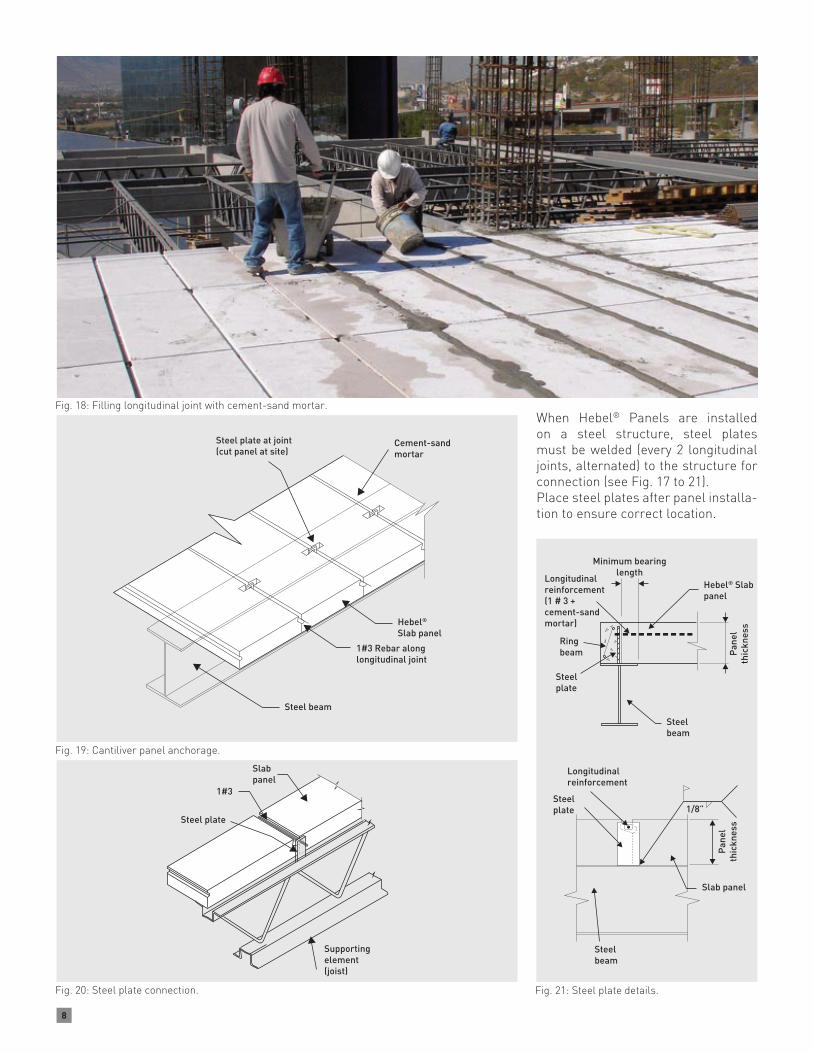
When Hebel® Panels are installed on a steel structure, steel plates must be welded (every 2 longitudinal joints, alternated) to the structure for connection (see Fig. 17 to 21).Place steel plates after panel installa-tion to ensure correct location.
Fig. 18: Filling longitudinal joint with cement-sand mortar.
Fig. 19: Cantiliver panel anchorage.
Fig. 20: Steel plate connection.
Slabpanel
1#3
Steel plate
Supportingelement(joist)
Fig. 21: Steel plate details.
Minimum bearinglength
Ringbeam
Steelplate
Steelbeam
Hebel® Slabpanel
Pan
elth
ickn
ess
Longitudinalreinforcement(1 # 3 + cement-sandmortar)
Steelplate
Steelbeam
Slab panel
1/8”
Pan
elth
ickn
ess
Longitudinalreinforcement
Cement-sandmortar
Steel plate at joint(cut panel at site)
Hebel® Slab panel
1#3 Rebar along longitudinal joint
Steel beam

9
3.5 Utilities Installation
Openings
Openings in floor and roofs for A/C ducts, staircases, roof windows, air exhausters, etc. are built using steel support. For more information, please call Xella Technical Department.
Electrical Conduits
Electrical conduits with a diameter ≤1” can be lodged through longitudinal joints on top or bottom of the panels. For electrical conduits >1” or several electrical conduits, longitudinal joints can be widened to lodge them. It is notrecommended to chase on top and across the panel width -transversal chase- (see Fig. 16).
It is possible to define cut surfaces in Panels regarding installations. For more information, please call Xella Technical Department.
Piping Lines
When required, PVC and other piping lines can pass through holes in the panels. The maximum hole diameter permitted in one panel is 6” or 12” in a joint between panels (6” each panel). If more than one hole is required, they must be aligned along the length of the panel. Only two longitudinal rebar in the bottom reinforcement of the panel can be cut (see Fig. 22 and 24) casting.
3.6 Panels Cutting
According to shop drawings, identify Hebel® Slab Panels to be cut. Per-missible cutting length is indicated on shop drawings, otherwise contact Xella Technical Department. Along its length, Hebel® Slab Panel can be cut 1/3” the width.
Cutting Equipment Options
Electric Circular Saw (8¼” blade diameter).Power Cutter (gasolinepowered) 12” blade or greater (see Fig. 23).
Cutting Procedures
a. Prepare a flat surface for cutting site.
b. Check dimensions of cuts to be made.
Fig. 22: Sanitary utilities. Fig. 24: Maximum dimensions of holes through slab panel.
Fig. 23: Power cutter.
Caution: Wear protective hel-met & visor, goggles, hear-ing and respiratory protection. Read equipment instruction manual. Inhalation of concrete dust above recommended expo-sure levels may be harmful. Wet sawing is recommended. Please consult the Xella Material Safety Data Sheet for further details.
c. For transversal cuts, wood pieces must be placed along the sides of the cut and at the edges of the panel.
d. For longitudinal cuts, wood pieces must be placed at every 6 ft. (max) for 6 to 12 in thick panels and every 4 ft for panels 4 to 5 in thick.
e. Check for full contact between wood pieces and panel. Wedge if necessary.
f. Place a ruler as a guide and trace the cut dimensions.
g. Proceed with panel cutting, veri-fying that cutting dimensions com-ply with specifications. Transver-sal and longitudinal cuts must be made with panel in horizontal po-sition; if full thickness is to be cut, perform cut from both sides.
h. Apply anticorrosive paint at rein-forced bar tips.
Incorrect
Correct
Hebel® Slabpanel
Aligned
6”
6”
6”
6”6”
6”6”

10
4 Renders and Finishes4.1 Products
Surface Patching
Use Hebel® Repair Mortar to patch chips, breaks and other imperfections on surfaces of Hebel® Slab Panels.
Hebel® Repair Mortar is prepared in a plastic bucket, adding water and mortar from the bag (see instructions on the bag) and mixed with a stirrer using a power drill or by manual means (depending on quantity to be used). It is applied using a spatula.
Fig. 25: Industrial and commercial projects.
Fig. 26: Housing projects.
11
Fig. 28: Multi-story building.
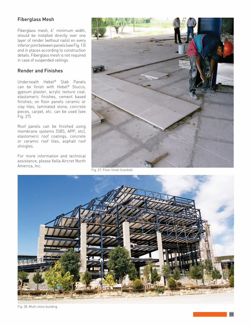
Fig. 27: Floor finish (marble).
Fiberglass Mesh
Fiberglass mesh, 6” minimum width, should be installed directly over one layer of render (without nails) en every inferior joint between panels (see Fig. 13) and in places according to construction details. Fiberglass mesh is not required in case of suspended ceilings.
Render and Finishes
Underneath Hebel® Slab Panels can be finish with Hebel® Stucco, gypsum plaster, acrylic texture coat, elastomeric finishes, cement based finishes; on floor panels ceramic or clay tiles, laminated stone, concrete pieces, carpet, etc. can be used (see Fig. 27).
Roof panels can be finished using membrane systems (SBS, APP, etc), elastomeric roof coatings, concrete or ceramic roof tiles, asphalt roof shingles.
For more information and technical assistance, please Xella Aircret North America, Inc.

12
5. FastnersFastenersAnchors used with AAC shall be made of plastic or nylon. Wood, fiber, lead, metal or expansión anchors are not recommended.Use power drills to make holes for fasteners and masonry drill-bits recommended (diameter) on table 9 ( drill-bit diameter may differ from recommended by fastener manufacturer; specifications have been adapted for AAC). Percusion drilling or inverting the rotation direction when drilling shall be avoided.The anchor shall penetrate tightly in the hole to avoid rotation when placing the screw. When using Fischer anchors, the external finish layer surrounding the hole should be removed to allow the anchor to fully penetrate into the AAC element.
Hebel® AAC Nail:Hebel® galvanized AAC nails are designed specifically to provide a definitive anchorage in the AAC. Hebel® AAC nails are directly hammered-into the AAC element – no drilling is required.
ScrewsAlways use screws of the diameter recommended on table 9. Minimum length of screw is defined by the anchor length plus the thickness of the finish layer and the thickness of the element to be fixed.
Precautions Load values (pull-out strength) shown in chart shall be used only as a reference guide; field testing is suggested according to project requirements.The load values (lb) shown in chart are for direct pull-out and a safety factor of 5 is included in them. Full penetration of screws into the anchor is assumed to obtain such load values.
Fig. 31: Minimum screw length. Fig. 30: Recommended nails & anchors.
Allowable Pull-Out LoadsAnchoring to Autoclaved Aerated Concrete
AAC Fasteners& Hebel® Nails
Anchor / NailDrill Bit Screw
Load Value* (pull-out strenght)
AAC-4 AAC-6
Length ØDiam Block & Panel
in in Ø in # or Ø in lb lb
Hebel® AAC Nail 4’’(1)
(min penetration: 3”)4 ¼ Fixed directly
with hammerNot
Required 51 88
Hebel® AAC Nail 4’’(1)(min penetration: 3”)
6 ¼ Fixed directlywith hammer
NotRequired 88 137
Universal Plastic Anchor(2) (For use in all solid walls)
11/8
11/2
2
¼5/163/8
¼5/165/16
#10#12¼
222644
263162
Thorsman(2)
Anchor Red TP 2X (4)
Anchor Brown TP 2BAnchor Blue TP 3
13/8
15/8
13/4
¼
5/163/8
3/16¼¼
5/16
#8#10#10#12
37---4973
---426284
TOX VLF(3) Anchor 6/70Anchor 8/80 - 8/135Anchor 10/100 - 10/160
23/4
31/8+
4+
¼5/163/8
¼5/163/8
Anchor with screws
included(pre-
assembled)
66102120
---------
HILTI(2)
Anchor HUD-1 (10x50)Anchor HUD-1 (12x60)
223/8
3/81/2
3/87/16
5/16 3/8
71128
90185
Fisher(1) Anchor GB10 (5)
Anchor GB14Anchor S10H80R
2
331/8
3/8
5/83/8
3/81/25/83/8
¼ ¼
3/85/16
126---165123
---104225150
Notes: (1)Available at Xella Aircrete North America, Inc. (2)Available at Hilti Shops, Home Depot, Lowe’s, etc. (3)Available at www.demandproducts.com (4)For AAC-6 (Block & Panel) use 1/4” drill bit. (5)ForAAC-6 (Block & Panel) use 1/2” drill bit. *Safety Factor [SF]=5. Use masonry drill bits. Anchorsdo not include screws (except TOX anchors).
Table 9: Anchoring into Hebel® AAC Masonry components.

13

14

15
Heb
el®
is a
reg
iste
red
trad
emar
k of
the
Xella
Gro
up.
July
201
3. P
rint
ed a
nd M
ade
in M
exic
o
Xella Aircrete North America, Inc900 Schneider Dr.Cibolo, Texas 78108
Phone (210) 402-3223 Fax (210) 402-6390
www.hebel-usa.com
Authorized Distributor