heavy haul infrastructure guidelines - artc haul guidelines signals... · heavy haul infrastructure...
TRANSCRIPT
This document is uncontrolled when printed
HEAVY HAULINFRASTRUCTURE
GUIDELINES
SIGNALS, COMMUNICATIONS ANDELECTRICAL
20 June 2013
Version 4.0
HEAVY HAULINFRASTRUCTURE GUIDELINES
SIGNALS, COMMUNICATIONS & ELECTRICAL
REV 4.0Page 2 of 44
Document OverviewClient: Australian Rail Track Corporation – Hunter Valley
Project: HEAVY HAUL
Document Title: HEAVY HAUL INFRASTRUCTURE GUIDELINES SIGNALS, COMMUNICATIONS ANDELECTRICAL
Date Issued: 20 June 2013
Revision: 4.0
Prepared By: J Gifford / M Blaik / A Malaviya / J Budden / C Crump
Document Owner: Heavy Haul Development Manager
Applicability Hunter Valley Heavy Haul Network
Purpose: These guidelines are not intended to replace any ARTC standards, but are to be usedas a supplement to deliver consistency in: design, systems provided, componentsinstalled, installation arrangements and deliverables applicable to the Heavy Haulrequirements of the Hunter Valley.
RelatedDocuments Heavy Haul Infrastructure Guidelines Track, Civil and Structures
Endorsed by: EGM Hunter Valley
Revision History
Revision Date Issued To Description
1.6 20 Mar 2008 ARTC version original release
1.7 9 Mar 2009 Supersedes version 1.6
1.8 31 Jul 2010 IM HV Align with 200+, reformatting, config mgt moved toH200+ Infrastructure Plan, reference made to OSC
1.9 13 Aug 2010 BIC Review, discussion
2.0 30 Nov 2010 HV users OSC clause added.
2.1 14 April 2011
HV Users, OSC,Standards,maintenance,performance
Formatting, minor updates, underbores, AppendicesC ,F and G added.
2.2 14 Feb 2013 HV200+ workinggroup Draft update not released
3.0 19 April 2013 Peer Review Group Major rewrite
4.0 20 June 2013 HV Users Final Draft after Peer Review
HEAVY HAULINFRASTRUCTURE GUIDELINES
SIGNALS, COMMUNICATIONS & ELECTRICAL
REV 4.0Page 3 of 44
CONTENTS
1 GENERAL ............................................................................................................................................52 SIGNALS .............................................................................................................................................7
2.1 General ....................................................................................................................................73 INTERLOCKING, CBI FIELD EQUIPMENT ................................................................................................8
3.1 General ....................................................................................................................................83.2 Computer Based Interlocking (CBI) .............................................................................................8
4 FIELD EQUIPMENT: TRACK CIRCUITS, TRACKSIDE EQUIPMENT ..............................................................94.1 Glued Insulated Joints (GIJs).......................................................................................................94.2 Axle Counters ...........................................................................................................................94.3 Audio Frequency (AF/Jointless) Track Circuits ............................................................................104.4 Coded Track Circuits ................................................................................................................104.5 Track Circuit Cabling and Bonding.............................................................................................10
5 POWER SUPPLY ................................................................................................................................115.1 Mains Power Supplies..............................................................................................................115.2 Standby Power Plants ..............................................................................................................115.3 Solar Power Systems ...............................................................................................................115.4 No-Break Power Supply for 120/240 Volt Mains Supply..............................................................115.5 Bypass Arrangements for No-Break Supplies .............................................................................125.6 Minimum Run Time for No-Break Supplies ................................................................................125.7 Earth Leakage Detection ..........................................................................................................125.8 Surge Protection .....................................................................................................................125.9 Power System Compliance and Certification..............................................................................13
6 POWER SYSTEM MONITORING AND ALARMS.....................................................................................146.1 General ..................................................................................................................................146.2 Standby Power Plants ..............................................................................................................146.3 Solar Systems..........................................................................................................................146.4 UPS Systems ...........................................................................................................................146.5 Earth Leakage Detectors ..........................................................................................................146.6 Level Crossing Equipment ........................................................................................................14
7 ENCLOSURES ....................................................................................................................................157.1 General ..................................................................................................................................15
8 CABLE PITS, CABLE ROUTES AND CONDUITS .......................................................................................168.1 General ..................................................................................................................................168.2 Trenching ...............................................................................................................................168.3 Underbores ............................................................................................................................16
9 TURNOUT DRIVE SYSTEMS ................................................................................................................179.1 General ..................................................................................................................................179.2 Preferred Systems and Suppliers ..............................................................................................179.3 New Functionality Points and Crossovers ..................................................................................179.4 EOL / ESML Cabinets and Manual/Emergency Operation (refer also to Appendix D). ....................18
10 TELEMETRY AND CONTROL SYSTEMS .................................................................................................1910.1 General ..................................................................................................................................19
11 LEVEL CROSSINGS .............................................................................................................................1911.1 Lamps ....................................................................................................................................1911.2 Wiring ....................................................................................................................................19
12 NEW CONNECTIONS, PRIVATE LOOPS AND SIDINGS ...........................................................................1912.1 General ..................................................................................................................................19
HEAVY HAULINFRASTRUCTURE GUIDELINES
SIGNALS, COMMUNICATIONS & ELECTRICAL
REV 4.0Page 4 of 44
13 APPENDICIES ....................................................................................................................................20Appendix A Hunter Valley Authorised Infrastructure Representatives .............................................20Appendix B UPS Termination Diagram ..........................................................................................21Appendix C Surge Protection and Earthing Arrangements ..............................................................22Appendix D Switch Identification and ESML/EOL Signage ...............................................................39

HEAVY HAULINFRASTRUCTURE GUIDELINES
SIGNALS, COMMUNICATIONS & ELECTRICAL
REV 4.0Page 5 of 44
1 GENERALThe objective of this document is to provide clear insight into the considerations required in designs,equipment types and configurations of infrastructure installed in the Hunter Valley Heavy Haul Network.These considerations are the core of the Hunter Valley Business Units’ key performance criteria with theplanned expansion of the coal throughput to the port of Newcastle, namely:
Improvement of operational reliability (reduction of asset failures), Improvement of asset availability (reduction of maintenance possession time) and The need to achieve prudent capital expenditure taking into account maintainability and asset
life cycle maintenance costs
1.1 Application to Works in the Corridor1.1.1 These guidelines are applicable only to the Hunter Valley Heavy Haul network as defined by
Figure 1 and/or Pricing Zones 1, 2, 3 and 4 of the Hunter Valley Coal Network Access Undertakingas amended from time to time.
Figure 1.1 – Hunter Valley Heavy Haul Network
1.1.2 Projects with a budget less than $100,000 will not be required to comply with this guideline asthese projects are typically small repairs to existing infrastructure. In these circumstances thefurther scope required to comply with these guidelines may generate an unnecessary costburden upon the project.Therefore the applicability of this guideline to most RCRM, MPM works will be determined by theManager Infrastructure and Planning (MIP) on a case-by-case basis during project scopedevelopment. The MIP will consider the scope of the project in context with the business unitobjectives of the Hunter Valley.
HEAVY HAULINFRASTRUCTURE GUIDELINES
SIGNALS, COMMUNICATIONS & ELECTRICAL
REV 4.0Page 6 of 44
1.1.3 Minor Capital, Major Capital and other projects with a budget of $100,000 or greater willgenerally be expected to adhere to these guidelines as published
1.1.4 Any departures in the application of these guidelines must be declared and presented forendorsement by the Operational Steering Committee (OSC), prior to implementation.Endorsement of these departures should be obtained from the Authorised InfrastructureRepresentative (AIR) - refer to Appendix A - prior to presentation at the OSC, however if this isnot possible due to an impasse then a joint presentation to the OSC is required by the projectowner and the AIR.
1.2 Interpretation of Guideline Clauses1.2.1 Where clarification is required to these guidelines – including conflict with current ARTC
standards (perceived or otherwise) – a technical query is to be forwarded to the AuthorisedInfrastructure Representative, or their nominated representative.
1.3 Innovative Solutions1.3.1 To meet the business objectives of the Hunter Valley Business Unit, the investigation and use of
new technological solutions in the field is encouraged. This document does not intend to restrictinnovation in design or the introduction of new technology.With respect to innovation, some sections of this document refer the reader to a preferredproprietary product or design solution – this is made in an attempt to avoid a situation where avariety of different spares, training requirement and equipment performance is experiencedthroughout the Heavy Haul.However, the mention of a preferred proprietary product or design solution shall not precludeother equipment or solutions to be considered, investigated and recommended by the projectteam.The recommendation of non-preferred products and solutions shall be considered a departurefrom the guidelines and are to be considered as per clause 1.1.4 above.
1.4 Design Concept, Review and Presentation1.4.1 Final designs for recently commissioned Hunter Valley projects are to be used as a baseline
model for projects with similar infrastructure configurations – this is to prevent starting fromscratch and also capturing lessons learnt during design phases of previous projects.
1.4.2 Hunter Valley main line signalling headways are to be designed to meet forecast capacityrequirements. For guidance on headways and other capacity requirements please refer to thecurrent version of the Hunter Valley Corridor Capacity Strategy which is publically available onARTC’s website <www.artc.com.au>
1.4.3 All concept plans, proposal specifications, designs, installation and commissioningdocumentation are to be reviewed and accepted by the Authorised Infrastructure Representative(see Appendix A) before any work is progressed.
1.4.4 Signalling Infrastructure to be shown on any related Track and Civil IFC drawings including GPScoordinates.
HEAVY HAULINFRASTRUCTURE GUIDELINES
SIGNALS, COMMUNICATIONS & ELECTRICAL
REV 4.0Page 7 of 44
2 SIGNALS2.1 General
2.1.1 Fixed signals and other track side signalling equipment shall not be located or installed in cessdrains and must comply with the detailed site survey plan, as agreed by the AuthorisedInfrastructure Representative (AIR)
2.1.2 Home, Starting and Shunt signals must not be placed on grades where there is a risk of wheel slipand resulting wheel burns.
2.1.3 Signals should be placed on straight sections to avoid the need of installing GIJs on curves. GIJs oncurves represent a reliability risk and incur increased maintenance, refer to Section 4.
2.1.4 As a safety consideration, fixed ladders are to be fitted to all new fixed signals. This will have anadditional benefit of more efficient maintenance with crews not required to carry portable laddersto access the signal head.
2.1.5 All weather access shall be provided to all track side signalling equipment. This may include stairs,access roads, ladders or walkways.Such access will be developed in liaison with the Local Team Manager and is subject to theapproval of the Operations Steering Committee. Refer also to the Heavy Haul InfrastructureGuidelines Track, Civil and Structures.
HEAVY HAULINFRASTRUCTURE GUIDELINES
SIGNALS, COMMUNICATIONS & ELECTRICAL
REV 4.0Page 8 of 44
3 INTERLOCKING, CBI FIELD EQUIPMENT3.1 General
3.1.1 Computer Based Interlocking (CBI) solutions are to be provided for all green-field sites.MicroLok II is the current preferred CBI solution, however the introduction of other CBI systemswill be considered as per clause 1.3.1.
3.1.2 Expansion of existing relay based interlocking for brown-field sites will not normally be considereddue to:
High lifecycle costs Industry phase out of this old technology (life time support is questionable) Introducing complex and high risk interfaces Reduced opportunity for extensive off site pre-commissioning testing
3.2 Computer Based Interlocking (CBI)3.2.1 All auto signal indications are to be logged but not displayed on the Train Control System (currently
Phoenix)3.2.2 All CBI’s are to be fitted with backup batteries for both signal lamp retaining and CBI backup.
The designer needs to consider the load and duration, including maintenance response time, whencalculating the number and size of the batteries. The nominal capacity shall be at least 4 hours.
3.2.3 All signal lamps supplied via a CBI lamp driver card shall be supplied from a type approved 12 voltpower supply via a type approved 12 to 16 volt DC to DC converter.The power supply arrangement shall be duplicated (i.e. maximum two power supplies per busbar)as to provide redundancy. The maximum load should not be greater than the 75% of the maximumrated load of any single component in the supply arrangement.
3.2.4 All CBI communication designs shall be subject to the acceptance of the Senior Control SystemsEngineer Hunter Valley or the nominated representative.
3.2.5 All CBI network switches / modems shall be installed in close proximity to the CBI within thesignalling equipment room or enclosure.
3.2.6 Each CBI network switch / modem shall be fitted with a fault alarm facility which shall provide anapproved indication of a fault condition. This shall comply with Hunter Valley alarm strategy andbe submitted for the acceptance of the Senior Signals and Control Systems Engineer the nominatedrepresentative Hunter Valley
3.2.7 All CBI network switches / modems shall be configured to provide a remote interface for bothdiagnostics and log retrieval.
3.2.8 Currently the RuggedCom RS400 modem is provided throughout the Hunter Valley for vital CBIcommunications. This device also provides a remote interface to CBIs for both diagnostics and logretrieval.Alternatives may be considered subject to clause 1.3.1 so long as the alternative provides the samefunctionality as a minimum.
3.2.9 The main interlocking site shall be provided with a complete version of the master circuit bookincluding; cover sheets and indexes for all locations controlled by the main interlocking, controlsheets, control table, track plan and track insulation plan.
3.2.10 Each CBI interlocking site shall be provided with an extract version of the master circuit bookapplicable to the CBI interlocking, signals, track circuits, power supplies etc at that site.The extract circuit books shall include all circuit diagrams, applicable to the area covered by thelocation.
HEAVY HAULINFRASTRUCTURE GUIDELINES
SIGNALS, COMMUNICATIONS & ELECTRICAL
REV 4.0Page 9 of 44
4 FIELD EQUIPMENT: TRACK CIRCUITS, TRACKSIDE EQUIPMENT4.1 Glued Insulated Joints (GIJs)
Glue Insulated Joints are a high maintenance asset and an inherent weak spot in the track infrastructure. Itis the strategic objective of the Hunter Valley to reduce/remove as many GIJs as possible due to theirreliability issues generated with the failure of the joint or the thermic welds associated with theirinstallation.However, traditional track circuit designs utilising GIJs also provide an important benefit namely; the abilityto identify potential broken rails (via a track circuit failure). Broken rail detection is something that theHunter Valley wishes to maintain; therefore the installation of other track circuit technologies mustconsider how the risk of broken rail detection will be covered by the new technology.The installation of GIJs is not a preferred option, however on a case-by-case basis, to retain broken raildetection and to easily integrate the scope into the existing interlocking GIJs may still be installed subject tothe below clauses.4.1.1 GIJs should not to be installed on curves due to:
Short life and poor reliability due to excessive curve rail wear Rail head flow on gauge face Higher risk of derailment if GIJ breaks in a curve situation.
4.1.2 Wherever possible, GIJs shall not be located on grades due to the potential for wheel burns causedby trains lifting heavy load on a grade (worst case scenario of wet conditions needs to beconsidered in any site assessment).
4.1.3 Placement of GIJs in turnouts to be determined on a ‘site by site’ basis to minimise GIJ wear andconsequential failure (direction of most traffic and dynamic lateral forces need to be considered inany site assessment).
4.2 Axle Counters4.2.1 Axle counters are a proven solution that may be used to support the strategy of minimising the
number of GIJ’s and the associated thermic welds.Installation of axle counter operated trackcircuits are the preferred at the following locations: Turnouts
Plain track sections on non-passenger lines (within crossing loop boundaries only) Within the Kooragang and Port Waratah Bulk Terminals
4.2.2 For standardisation Frausher axle counters are preferred, however variation may be permittedsubject to clause 1.3.1.
4.2.3 Axle counter reset must comply with ARTC’s cooperative sweep release and reset procedure issuedas engineering waiver HV-SG-0010 and standard design requirements as directed by the SignalsStandards Engineer.
4.2.4 Frausher ACS 2000 Axle counters shall be configured in “isolation mode” only. As we migrate toFrausher’s FADC digital axle counters they will be inherently “transmission mode”.
4.2.5 All Frausher axle counters evaluator boards installed in the Hunter Valley Corridor must be modelIMC006. This is to avoid miscounts previously experienced due to the smaller wheel on hi-railbased track machines.Project managers should note due to changes in technology or manufactures specifications thismay change without notice. Confirmation should be sought from the Signal Maintenance Engineeras to preferred evaluator board for the applicable application.
4.2.6 In areas where impulse track or other circuits are currently installed over points, Project Managersmust seek advice from the Authorised Infrastructure Representative as to the train detectionarrangements to be provided.
4.2.7 Consideration should be given to additional battery backup for axle counters installed at levelcrossings
HEAVY HAULINFRASTRUCTURE GUIDELINES
SIGNALS, COMMUNICATIONS & ELECTRICAL
REV 4.0Page 10 of 44
4.3 Audio Frequency (AF/Jointless) Track Circuits4.3.1 To be used at all locations where it is not proposed to utilise coded track circuits or axle counters.4.3.2 UM71 or TI21 Digital type is preferred.4.3.3 Capacitor compensated audio track circuits will only be considered for installation in exceptional
circumstances.
4.4 Coded Track Circuits4.4.1 Coded track circuits are preferred for medium to low density long block sections (typically beyond
Muswellbrook) where it is cost prohibitive to install audio frequency track circuits and where axlecounter technology is not acceptable.
4.4.2 Microtrax coded track circuits are preferred, although alternative coded track circuit products maybe considered subject too clause 1.3.1
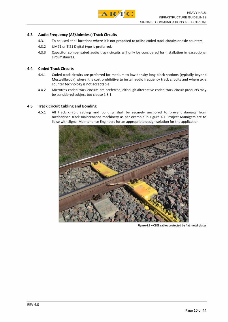
4.5 Track Circuit Cabling and Bonding4.5.1 All track circuit cabling and bonding shall be securely anchored to prevent damage from
mechanised track maintenance machinery as per example in Figure 4.1. Project Managers are toliaise with Signal Maintenance Engineers for an appropriate design solution for the application.
Figure 4.1 – CSEE cables protected by flat metal plates
HEAVY HAULINFRASTRUCTURE GUIDELINES
SIGNALS, COMMUNICATIONS & ELECTRICAL
REV 4.0Page 11 of 44
5 POWER SUPPLY5.1 Mains Power Supplies
5.1.1 Local energy provider to provide primary supply.5.1.2 Redundancy is to be provided by a no-break supply backup to the signalling supply busbar, it will
not be necessary to backup the points supply busbar.5.1.3 Where power supplies are reticulated at 120 V or 415 V from a main power room for both local
and external supplies (i.e. North and South or East and West) then the external and local suppliesmust be backed up by separate no-break supply units. The failure of a single no-break supply mustnot fail the whole station or interlocking.
5.1.4 At interlockings with power operated point motors, a motor generator (MG) plus a no-breaksupply for changeover is required. Consideration will be given to a no-break supply onlyarrangement in low train density situations.
5.2 Standby Power Plants5.2.1 A suitable shelter or enclosure is to be provided for outdoor motor generators to prevent
corrosion of the housing and water ingress into the control equipment.
5.3 Solar Power Systems5.3.1 Solar Power systems may only be utilised where mains power is unavailable and as accepted by the
Senior Signal and Control Systems Engineer or Signal Manager (Hunter Valley). Typically they maybe used for distant, outer home, or in-section signal location in medium and low density trafficareas subject to ARTC’s approval. It should not be assumed that solar systems will be approvedeven where solar power systems currently exist in the area.
5.3.2 Solar power installations must be designed by a power engineer experienced in solar power supplysystems.
5.3.3 Solar battery systems must provide a minimum of 7 days capacity without charging based on acontinuous maximum load.
5.3.4 Solar panels and batteries must be chemically etched “STOLEN FROM ARTC” and the manufacturerand serial number/s, where available, must be recorded on the history card.
5.4 No-Break Power Supply for 120/240 Volt Mains Supply5.4.1 The preferred No-Break supply units for installation in the Hunter Valley are Eaton Powerware
9130 series and 9155 series.5.4.2 No-break supplies shall be split to best service the load and power distribution.5.4.3 Parallel no-break supply arrangements will not be approved by ARTC.5.4.4 The maximum capacity of any single no-break supply which can be installed at a field location is
6KVA.Subject to the approval of the Senior Signal and Control Systems Engineer Hunter Valley, largercapacity no-break power units may be considered at major interlockings provided:(i) permanently connected reverse cycle air conditioning is installed or other effective passive
cooling mechanism5.4.5 Other equivalent No-Break Supplies may be considered as per clause 1.3.1, provided they are
equivalent or better in performance and meet the following requirements;
Changeover between supplies to be less than 20ms. The No-Break supply must have ethernet based monitoring capability. All components of the No-Break supply must be 19 inch rack mountable. Comply with sections 5.4.2 and 5.4.3
HEAVY HAULINFRASTRUCTURE GUIDELINES
SIGNALS, COMMUNICATIONS & ELECTRICAL
REV 4.0Page 12 of 44
5.5 Bypass Arrangements for No-Break Supplies5.5.1 A manual bypass switch shall be fitted to all no-break supply units installed.5.5.2 The installed no-break supply shall be provided with a manufacturer’s internal auto-bypass
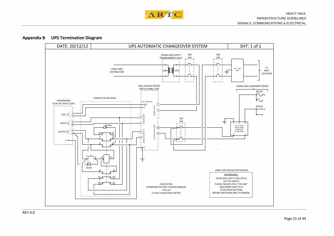
arrangement which is activated when a no-break supply internal fault is detected.5.5.3 An additional external automatic bypass arrangement is to be installed to provide for failure of the
no-break supply unit failing to go into the internal automatic bypass mode (see Appendix B for acontemporary wiring arrangement).
5.6 Minimum Run Time for No-Break Supplies5.6.1 10 hours at full load capacity for auto/block sections where no standby power plant is provided.5.6.2 15 minutes at full load or standard manufacturer’s run time at full load, whichever is the greater,
where a standby power plant is provided.
5.7 Earth Leakage Detection5.7.1 Earth Leakage Detectors (ELDs – MRD AC/DC type) are to be fitted to all mains external and
internal busbars including 12 V, 15 V, 24 V, 50 V, 120 V, and 415 V.5.7.2 Preferred product is MRD AC/DC digital display model.
Other equivalent or compatible products may be considered as per 1.3.1, provided they areequivalent or better in performance and as a minimum offer: no alarm raised on power interruption alarm status retained following power interruption
minimum 3 days retention of time activation of alarm display of earth leak value
5.8 Surge Protection5.8.1 Surge protection systems must meet ARTC standards. Primary Rail Filter technology is to be used
on all IVAP panels, alternative equivalent technologies will be considered for inclusion in thestandard on a case by case basis.
5.8.2 Upgrading of earthing specifications are to meet current recommendations from ERICO.5.8.3 Surge protection devices shall be installed in the Main Distribution board for protection of the
“Consumers Mains”.5.8.4 The signalling location earth grid earth stakes shall be connected together by flat copper earth
strap (not stainless steel wire) in accordance with current recommendations from ERICO.5.8.5 Consumers, mains supplied equipment, mains supply and building earths shall be connected to a
separate earth busbar to that of the Signalling Equipment earths and location earth grid. Bothearth busbars shall be connected by a transient earth clamp.
5.8.6 Communications aerials, towers, etc, shall be connected to the signalling earth grid via a transientearth clamp.
HEAVY HAULINFRASTRUCTURE GUIDELINES
SIGNALS, COMMUNICATIONS & ELECTRICAL
REV 4.0Page 13 of 44
5.9 Power System Compliance and Certification5.9.1 Signalling power systems shall be designed to comply with the Australian Standard AS 3000 and
ARTC Electrical Standards and Procedures. However, the current signalling specifications may notallow full compliance with Section 7.4 of AS3000 on “Separated Supplies”. Until the signallingspecifications are revised, the following principles shall be adopted in the designs of signallingpower systems:• The signalling locations with 240V MEN supply from the local energy provider shall be provided
with two independent earths – an MEN Earth and a Signalling Earth (Lightning ProtectionEarth);
• All exposed conducting surfaces associated with MEN and back up supplies shall be connectedto the MEN Earth;
• All exposed conducting surfaces associated with the ‘separated supplies’ shall be connected tothe Signalling Earth;
• Earth terminals of Surge Protection Devices shall be installed inside non-conducting enclosures;• Protection against electric shock hazard (due to touch voltages) shall be achieved by placing the
MEN supply equipment ‘out of reach’ of the systems and equipment associated with theseparated supplies. Further protection can be achieved by using equipment enclosures made ofnon-conducting materials for the separated supply equipment.However, in order to remove the shock hazard completely from the metal relay room buildings,the relay and power rooms must be physically separated and each building must be connectedto the earths as follows – power room to the MEN Earth and relay room to the Signalling Earth;
• The signalling locations without a direct 240V MEN supply shall be provided with just one earthto avoid touch voltage problems; and
• Signalling locations shall be located in such a way that they are well clear of high voltage (11kV)earth rods.
5.9.2 Installation of signalling power systems must be undertaken in accordance with AS 3000 and theNSW “The Electrical (Consumer Safety) Act 2004 and Electrical (Consumer Safety) Regulation2006”. All work must be performed by installers holding a current NSW Electrical Supervisor’sLicence and ARTC Statement of Competency. This applies to all electrical equipment installation,repair, testing and certification activities on voltages equal and above 50V AC and 100V DC.
5.9.3 The installing contractor or contractors shall submit a Certificate of Compliance to the local supplyauthority in accordance with the NSW “The Electrical (Consumer Safety) Act 2004 and Electrical(Consumer Safety) Regulation 2006. Two copies of the Certificate of Compliance shall be providedto ARTC. One copy shall be included in the signalling commissioning work package (CWP) for theproject and the other copy shall be forwarded to the Senior Signals and Control Systems EngineerHunter Valley or the Hunter Valley electrical representative. This applies to all electrical equipmentinstallation and modification activities on voltages equal and above of 50V AC and 100V DC.
HEAVY HAULINFRASTRUCTURE GUIDELINES
SIGNALS, COMMUNICATIONS & ELECTRICAL
REV 4.0Page 14 of 44
6 POWER SYSTEM MONITORING AND ALARMS6.1 General
6.1.1 The Hunter Valley power systems are remotely condition monitored and logged. Alarm anddiagnostic events are captured and managed through ARTC’s Hunter Valley Alarm ManagementSystem.
6.1.2 All equipment alarm and warning indications shall be available both locally and remotely,interfacing with remote diagnostic systems such as MOXA I/O logic Module (E2210) which providesan Ethernet with a TCP/IP interface to facilitate remote capture and logging of events and faults.
6.1.3 Power supply alarm (critical) status to be provided to the remote control centre for operatormonitoring via the Phoenix train control system or other nominated monitoring system.
6.1.4 Power supply warning and alarm indications shall be captured by a MOXA I/O Logic Module(E2210) to facilitate remote capture and logging of events and faults.
6.1.5 All Power System monitoring and alarm devices must be capable of interfacing with ARTC’s HunterValley and Corporate Alarm Management diagnostic and alarm management system.
6.2 Standby Power Plants6.2.1 The standby power plant controller shall be able to log system events and faults for recall and
diagnostics.6.2.2 Standby power plant alarm and warning indications must include availability of mains supply, low
fuel, low battery and plant failure.
6.3 Solar Systems6.3.1 In addition to the standard alarms the system must provide logging and remote alarm indication
capability when the solar panel is disconnected or removed (stolen).6.3.2 Additional alarm indications shall be provided for battery condition when an excessive load is
detected or the battery reaches a level of <50% the total battery capacity.
6.4 UPS Systems6.4.1 The no-break supply alarms shall be captured by the manufacturers approved interface card which
provides an Ethernet port with a TCP/IP interface to facilitate remote capture and logging of eventsand faults.
6.5 Earth Leakage Detectors6.5.1 Alarms shall also be captured by a MOXA I/O Logic Module (E2210) which provides an Ethernet
with a TCP/IP interface to facilitate remote capture and logging of events and faults.
6.6 Level Crossing Equipment6.6.1 Level crossing “Alarm” and “Warning” condition indications shall be provided to the network
controller NCCN Broadmeadow. The alarm and warning indications shall be provided for all levelcrossings in the Hunter Valley corridor. The indications shall be provided on the networkcontrollers Phoenix screen adjacent to the position of the level crossing and on the alarm summarypage.
6.6.2 Communications of these “Alarm” and “Warning” conditions to the Phoenix control system shallbe direct via the field interlocking equipment or continuously on line telemetry system.
6.6.3 Where a telemetry system is utilised the state of the telemetry link shall be monitored for“Health”. A failure of the telemetry link will raise the level crossing “Alarm” condition on thenetwork controllers Phoenix screen for the affected level crossing.
HEAVY HAULINFRASTRUCTURE GUIDELINES
SIGNALS, COMMUNICATIONS & ELECTRICAL
REV 4.0Page 15 of 44
7 ENCLOSURES7.1 General
7.1.1 Walk-in locations shall be provided for housing axle counter and no-break supply equipment.7.1.2 All signal enclosures and locations must be fully sealed as to prevent entry of moisture and
rodents. This is to include sealing of cable ways, conduits including spares, fitting of PVC barrier inbase of location cases, cable entry points, fitting of vermin proofing to air vents, and sealing ofspace between concrete slab and floor of free standing buildings.
7.1.3 All equipment enclosures should also be provided with an ‘A3’ size vermin and weather proofresealable enclosure for housing circuit books and maintenance history cards.
7.1.4 CBI interlocking locations cases shall also be provided with suitable vermin and weather proofresealable enclosure suitable for the housing of signalling and track insulation plans.
7.1.5 All non-air conditioned signalling equipment and power locations are to be fitted with ventilationincluding:
Low easy maintenance filters and vermin proofing must be fitted to all vents. The filteringshall be such to prevent the ingress of dust but allow the free flow of air.
All location doors fitted with long life, low maintenance seals as to prevent the ingress of dustand vermin.
Removable dust filters must be fitted to all signal location vents. These filters must bemanufactured for easy removal, cleaning and replacement of filter material
7.1.6 A laminated Terminal and Fuse analysis sheet shall be affixed to the inside of location case doors.In relay rooms and walk-in equipment housings this sheet shall be affixed adjacent to theTermination and Fuse racks.
7.1.7 Signalling equipment locations which house Electronic equipment such as no-break supplies, CBI,Axle Counter, Solar charging, switch mode power supplies, etc shall be temperature stabilised(preferably by passive means) to ensure the equipment operates within the manufacturesrecommended ambient specification. .
7.1.8 Bollards shall be installed adjacent to all signal locations and track side equipment to protect thelocation and equipment from being damaged by passing or reversing vehicles.
7.1.9 All signalling enclosures fitted with in a 19 inch rack shall be fitted with a slide out shelf and surfacemount 120 V plug socket (within the 19 inch rack) to allow placement and connection of a laptopcomputer or other test equipment. This socket is to be protected with a 4A fuse.
7.1.10 The Contractor together with the Signals Maintenance Engineer shall determine the most suitablesite for the positioning of each signalling equipment location case and building. This will beundertaken in conjunction with the Detailed Site Survey (DSS) and Site Interface Agreement (SIA)project walk through.
7.1.11 Due to increasing vandalism some signalling equipment locations may require additional securitymeasures to be installed. This may include security fencing and security cameras.This requirement is to be determined during the Site Integrity Agreement Inspection andassociated documentation.
HEAVY HAULINFRASTRUCTURE GUIDELINES
SIGNALS, COMMUNICATIONS & ELECTRICAL
REV 4.0Page 16 of 44
8 CABLE PITS, CABLE ROUTES AND CONDUITS8.1 General
8.1.1 This section is to compliment ARTC Standard ESC-11-01 “Construction of Cable Route andassociated civil works”. NOTE: all cable routes are to be re-enterable.
8.1.2 Cable runs where no metallic cables are installed shall have a continuous long-life conductorinstalled in the conduit which must pass through all cable pits in the route. Braided metallic tapesare not acceptable.
8.1.3 Flexible conduits shall be used for mechanical protection of electrical cables.8.1.4 “Flexicon” brand flexible conduits and fittings is the only brand currently type approved for this
application. Alternative brand components maybe considered subject to ARTC type approval,application suitability and durability. Project Managers shall seek advice from the SignalMaintenance Engineer Hunter Valley regarding alternative approved flexible conduits and fittings.
8.1.5 All conduits shall be sealed, but re-enterable, to prevent the entry of moisture and rodents. Sealingshall be performed where conduits enter cable pits, location cases, equipment rooms, powerrooms, communication rooms, track side equipment, signal bases and where flexible conduitsmeet rigid conduits.
Expanding foam filler is not to be used. Weak sand and cement mix is to be used to seal the cable entry/conduit end/s with suitable
wading to support the concrete mix and a wire piece to be imbedded to facilitate easyremoval.
8.2 Trenching8.2.1 All trenching must be compacted adequately to prevent water ingress and bearing failure of the
trench.Trenching in areas such as top drains, at the base of embankments and along/through access roadshave in the past been left uncompacted leading to top drain failures, embankment slips andmaintenance vehicles becoming bogged.
8.2.2 Refer to Section 10.3 of Heavy Haul Infrastructure Guidelines: Track, Civil and Structures.
8.3 Underbores8.3.1 Utility Services and Pipeline Underbores under are to comply with ETG 17-01 which in turn
references AS 4799.The exception being that the minimum depth to the underbore obverts (highest point of theinternal pipe surface) is to be 2 m below rail level.
HEAVY HAULINFRASTRUCTURE GUIDELINES
SIGNALS, COMMUNICATIONS & ELECTRICAL
REV 4.0Page 17 of 44
9 TURNOUT DRIVE SYSTEMS9.1 General
When designing points drive systems consideration to the harsh operating environment (including debrisand water ingress) and the need for low maintenance equipment must be factored into the selection ofdrive solutions.9.1.1 In-bearer point drive systems are required for most applications in the Hunter Valley. The
Authorised Infrastructure Representative (Appendix A) is to be consulted in determining the needfor in-bearer point drive systems. Reference should also be made to section 4 of the InfrastructureGuidelines Track, Civil and Structures.
9.1.2 The design of the in-bearer configuration should aim to maximise ease of maintenance.9.1.3 All in-bearer point rodding arrangements shall be fitted with covers to prevent the entry of split
coal or ballast.9.1.4 All point bearers that house signalling equipment shall be securely anchored to the stock rails to
prevent their movement during tamping operations.9.1.5 Each point end and detector shall have a discrete detection input.9.1.6 Back drive rodding should be installed on the straight leg of turnouts if possible.9.1.7 It is preferred that point machines and separate detectors should be fitted with internal wiring
terminated on a high impact non corrosive weatherproof (minimum IP56) electrical plug couplersto allow quick removal of cabling to components.
9.1.8 Utilisation of IP67 rated point drive motor machine housing in locations where high risk of waterinundation or coal dust ingress is encountered, especially dump station departure is encouraged.
9.1.9 All termination boxes shall not impede the safe manual operation of or access by maintainers topoint mechanisms. The termination box shall be placed no closer than 3 m from the nearest rail.Preference should be given to the installation of point machines in the “cess” rather than the “6foot”.Project managers shall liaise with Signal Maintenance Engineer Hunter Valley, to ensureappropriate installation arrangements are incorporated into their project scope.
9.2 Preferred Systems and Suppliers9.2.1 Unless otherwise approved all new points and SNX drives installed shall be fitted with Spherolocks,
applicable rodding and back drive system.9.2.2 The preferred ‘In Bearer” point mechanism for the operation of the Spherolock point locking
system is the D84M ‘in-bearer’.9.2.3 Cogifer MCEM91 integrated point machine and back drive system may also be acceptable subject
the agreement of Signal Maintenance Engineer.9.2.4 Alternative point machines may be considered subject to the approval of Signal Maintenance
Engineer Hunter Valley. These may include Westinghouse D84M, Westinghouse M23A andSiemens S700K.
9.3 New Functionality Points and Crossovers9.3.1 ARTC is currently developing new facilities to improve maintainability and availability for points
and crossovers installed in multiple line areas.(i) Facilities shall be provided to enable maintenance of individual point ends and SNX on
each line without impacting other lines – the facility will be known as “Split PointDetection” (SPD).
(ii) Facilities shall be provided to operate the points and crossovers under power when theinterlocking, remote control or dead locking track circuit fails. It will also be available tofacilitate local control and power operation of the points during track possessions – thisfacility will be known as “Emergency Power Operation of Points” (EPOP)
HEAVY HAULINFRASTRUCTURE GUIDELINES
SIGNALS, COMMUNICATIONS & ELECTRICAL
REV 4.0Page 18 of 44
9.3.2 Project Managers shall liaise with Signal Maintenance Engineer Hunter Valley as to the status ofthis new initiatives and functionality to ensure current strategies are incorporated into theirproject scope.
9.4 EOL / ESML Cabinets and Manual/Emergency Operation (refer also to Appendix D).9.4.1 Manual operating mechanism is to comply with WH&S manual handling standards, especially in
the area of loading when operating from a compromised ergonomic position.9.4.2 The EOL box design must safely secure all the point clips, point handles and SL locks. The design
must comply with the Hunter Valley design template and be approved by the Signal MaintenanceEngineer Hunter Valley.
9.4.3 Point numbers, switch identification and EOL signage must be attached to points and SNXs inaccordance with these guidelines. A plate shall also be fitted to all point and SNX stock railsindicating the correct positioning of emergency point clips – refer to Appendix D for furtherinformation and examples.
HEAVY HAULINFRASTRUCTURE GUIDELINES
SIGNALS, COMMUNICATIONS & ELECTRICAL
REV 4.0Page 19 of 44
10 TELEMETRY AND CONTROL SYSTEMS10.1 General
10.1.1 Control Systems and Telemetry system software (data) together with their communicationsdesigns shall be subject to the review and acceptance of the Senior Control Systems EngineerHunter Valley
10.1.2 For standardisation purposes Kingfisher is the only acceptable product at this time. This is due toits proven performance, proven support, generic ARTC data design templates available, excellentlogging and diagnostics capability together with ARTC’s need to rationalise spares and minimisestaff training. Alternative comparable and compatible products may be considered provided thesystem has the appropriate OEM or nominated Australian representative long term support.Consideration is subject to the acceptance of the Senior Control Systems Engineer Hunter Valley.
10.1.3 Phoenix is the standard control system adopted throughout the ARTC network including theHunter Valley. All proposed modifications to the Phoenix systems including modifications theNetwork Controller’s display shall be reviewed and approved by the Operations Manager HunterValley and subject to the acceptance of the Senior Control Systems Engineer Hunter Valley.
11 LEVEL CROSSINGS11.1 Lamps
11.1.1 All Level Crossings shall be fitted with Alstom FLO3 type F highway lamps. Alternative comparableproducts be may considered provided they prove compatible with Cerberus level crossingmonitoring system and are approved the Senior Signal and Control Systems Engineer HunterValley.
11.2 Wiring11.2.1 All wiring to F type Highway Lamps from location building terminations shall have a minimum size
of 16 mm2.11.2.2 Where Level crossing controls interface with CBI equipment provision shall be made to ensure
that any failure of the CBI or CBI communications links does not affect the normal operation ofthe level crossing equipment (i.e. the crossing equipment shall detect all approaching rail trafficoperating normally and correctly for the passage of all rail traffic).
12 NEW CONNECTIONS, PRIVATE LOOPS AND SIDINGS12.1 General
12.1.1 All new sidings are to provide for turnout and siding capacity to facilitate the whole of trainexiting the main line at 80 kph or otherwise agreed by the Hunter Valley Operations Manager orOperational Steering Committee via approval of the functional requirements.
12.1.2 Maintenance Isolating Switches are required to facilitate safe access for maintenance within theloop or siding.Project Managers shall liaise with Signal Maintenance Engineer Hunter Valley as to the locationand arrangement of these isolation switches for incorporation into their project scope.
12.1.3 Where the signalling in the private facility interfaces or is controlled or released by ARTCsignalling control systems then the signalling in the private facility shall be designed, installed andmaintained in accordance with ARTC Signalling Standards and Procedures and these guidelines.
HEAVY HAULINFRASTRUCTURE GUIDELINES
SIGNALS, COMMUNICATIONS & ELECTRICAL
REV 4.0Page 20 of 44
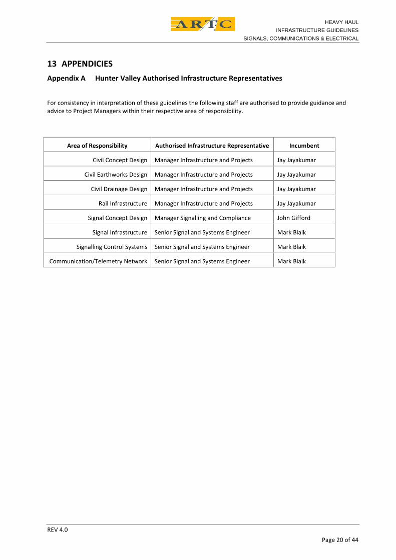
13 APPENDICIESAppendix A Hunter Valley Authorised Infrastructure Representatives
For consistency in interpretation of these guidelines the following staff are authorised to provide guidance andadvice to Project Managers within their respective area of responsibility.
Area of Responsibility Authorised Infrastructure Representative Incumbent
Civil Concept Design Manager Infrastructure and Projects Jay Jayakumar
Civil Earthworks Design Manager Infrastructure and Projects Jay Jayakumar
Civil Drainage Design Manager Infrastructure and Projects Jay Jayakumar
Rail Infrastructure Manager Infrastructure and Projects Jay Jayakumar
Signal Concept Design Manager Signalling and Compliance John Gifford
Signal Infrastructure Senior Signal and Systems Engineer Mark Blaik
Signalling Control Systems Senior Signal and Systems Engineer Mark Blaik
Communication/Telemetry Network Senior Signal and Systems Engineer Mark Blaik
HEAVY HAULINFRASTRUCTURE GUIDELINES
SIGNALS, COMMUNICATIONS & ELECTRICAL
REV 4.0Page 21 of 44
Appendix B UPS Termination Diagram
2
4
9
11
10
12
1
3
POWERWARE9130 UPS 3KVA (120V)
12
AN
AN
EPO
INPUT
OUTPUT
3 4
22 21
2
4
1
3
A1A2
13 14
R1
R3 R4
R2
E
E
FROM 240VDISTRIBUTION
N/CC
240V 120V
TCA TC-20A/LSINGLE PHASE
TRANSIENTFILTER CLAMP
E A N
A N
(FRO
MU
PSO
UTP
UT)
(TO
PRO
TECT
EDLO
AD)(T
OU
PSIN
PUT) (F
ROM
UTI
LITY
)
AUX. CONTACTS
WALL MOUNT BYPASSSWITCH (MBS) 120V
SIGNALLING SUPPLYTRANSFORMER 2.5KVA
CB316A
CB410A
PRF – 50A120V
DATE: 20/12/12 UPS AUTOMATIC CHANGEOVER SYSTEM SHT: 1 of 1
BX120
NX120
SIGNALLING EQUIPMENT ROOM
TONEXT
LOCATION
CB216A
CONTACTOR HOUSING
CONTACTOR:SCHNEIDER ELECTRIC (TELEMECANIQUE)
110v coilContact rating 25Amp @230v
f1
t1
WARNING;WHEN RED LIGHT IS ON, UPS IS
OUT OF CIRCUITPLEASE ENSURE UPS IS “ON LINE”
AND GREEN LIGHT IS LIT(PUSH RESET BUTTON)
BEFORE SWITCHING MBS TO NORMAL
LABEL FOR CONTACTOR HOUSINGGreen
Red
HEAVY HAULINFRASTRUCTURE GUIDELINES
SIGNALS, COMMUNICATIONS & ELECTRICAL
REV 4.0Page 22 of 44
Appendix C Surge Protection and Earthing ArrangementsC.1 GeneralThe ARTC Signalling Construction Specifications, “Lightning and Surge Protection Requirements” ESC-09-02 and SCP-04 details ARTC performance specification for Lightning and Surge Protection requirements.This document details installation practices to achieve the requirements.Reference documents
(i) Signalling Surge protection – Installation Guidelines, 20 November 2002, RAILINFRASTRUCTURE CORPORATION
(ii) Grounding Design Evolution Report, 12 March 2008, ARTC (prepared by Erico, Iac)
C.2 Separation From or Bonding to Other Earths
C2.1 Communications earths
Communications earths must be direct bonded to the power earth as per ACA rules thereforethe installation of signalling earths only needs to consider the low voltage and high voltagepower earths.
C2.2 High voltage earths
ARTC Electrical Systems Requirements document “Co-ordination of Signalling and powerSystems – Earth Potential Rise” EP 90 10 00 04 SP details the requirements for themanagement of the High Voltage and Signalling earths.
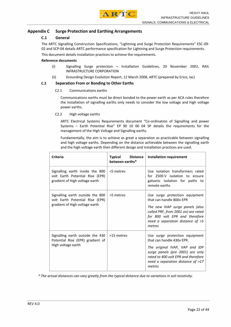
Fundamentally, the aim is to achieve as great a separation as practicable between signallingand high voltage earths. Depending on the distance achievable between the signalling earthand the high voltage earth then different design and installation practices are used.
Criteria Typical Distancebetween earths*
Installation requirement
Signalling earth inside the 800volt Earth Potential Rise (EPR)gradient of High voltage earth
<5 metres Use isolation transformers ratedfor 2500 V isolation to ensuregalvanic isolation for paths toremote earths
Signalling earth outside the 800volt Earth Potential Rise (EPR)gradient of High voltage earth
>5 metres Use surge protection equipmentthat can handle 800v EPR
The new IVAP surge panels (alsocalled PRF, from 2001 on) are ratedfor 800 volt EPR and thereforeneed a separation distance of >5metres
Signalling earth outside the 430Potential Rise (EPR) gradient ofHigh voltage earth
>15 metres Use surge protection equipmentthat can handle 430v EPR.
The original IVAP, VAP and IDPsurge panels (pre 2001) are onlyrated to 400 volt EPR and thereforeneed a separation distance of >17metres
* The actual distances can vary greatly from the typical distance due to variations in soil resistivity.
HEAVY HAULINFRASTRUCTURE GUIDELINES
SIGNALS, COMMUNICATIONS & ELECTRICAL
REV 4.0Page 23 of 44
C.3 Earth Wiring Guidelines
Single 4mm2 earth wires for surge protection must not be more than 0.5m long.
Single 16mm2 earth wires for surge protection must not be more than 0.5m long.
Paired 16mm2 earth wires for surge protection within equipment locations must be separated by15mm,and must not be more than 1m long when used in equipment locations.
Earth bars should be extended if earth wires will otherwise exceed the limits or braid wiring of equivalentsize used.
Connections between the subsidiary earth bars and the main earth bar can exceed the distance limits.
C.4 Wiring Separation Guidelines
C4.1 General
Surge protected wiring must be physically separated from non-surge protected wiring.
The separation criteria are given in sections 8.2 and 8.3. If the separation cannot be achievedthen a barrier consisting of an earthed piece of metal work is an acceptable solution to providethe separation.
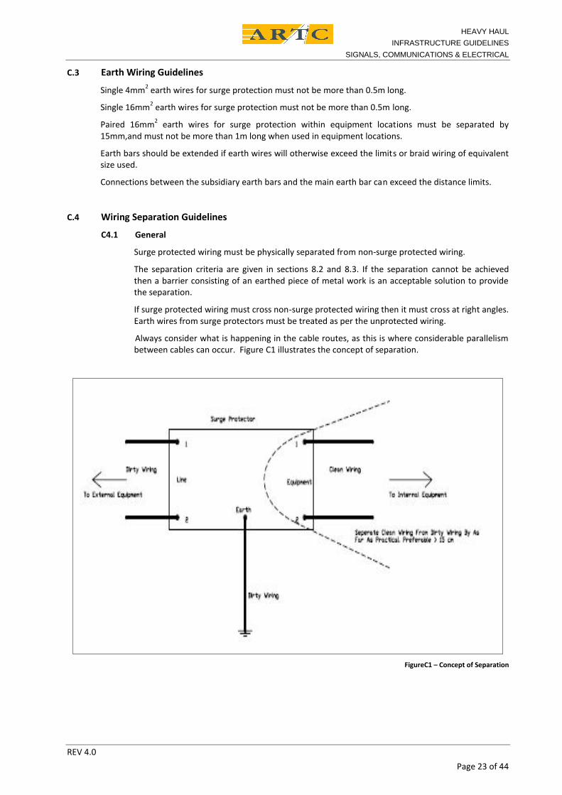
If surge protected wiring must cross non-surge protected wiring then it must cross at right angles.Earth wires from surge protectors must be treated as per the unprotected wiring.
Always consider what is happening in the cable routes, as this is where considerable parallelismbetween cables can occur. Figure C1 illustrates the concept of separation.
FigureC1 – Concept of Separation
HEAVY HAULINFRASTRUCTURE GUIDELINES
SIGNALS, COMMUNICATIONS & ELECTRICAL
REV 4.0Page 24 of 44
C4.2 Absolute separation (includes wiring crossing at right angles)
SeparationDistance
InternalWiring
Zone A wiring Zone B wiring Zone C wiring
Internal wiring 0mm 5mm 15mm 30mm
Zone A wiring 5mm 0mm 5mm 15mm
Zone B wiring 15mm 5mm 0mm 15mm
Zone C wiring 30mm 15mm 15mm 0mm
C4.3 Separation for more than 1 metre of parallelism
SeparationDistance
InternalWiring
Zone A wiring Zone B wiring Zone C wiring
Internal wiring 0mm 50mm 150mm 300mm
Zone A wiring 50mm 0mm 50mm 150mm
Zone B wiring 150mm 50mm 0mm 150mm
Zone C wiring 300mm 150mm 150mm 0mm
Zone A - Circuits from other equipment rooms.
Zone B - Circuits from external cables
Zone C - Circuits from overhead power lines or pole route.
C.5 Examples of Good and Bad Wiring Practice
C5.1 Surge Protection
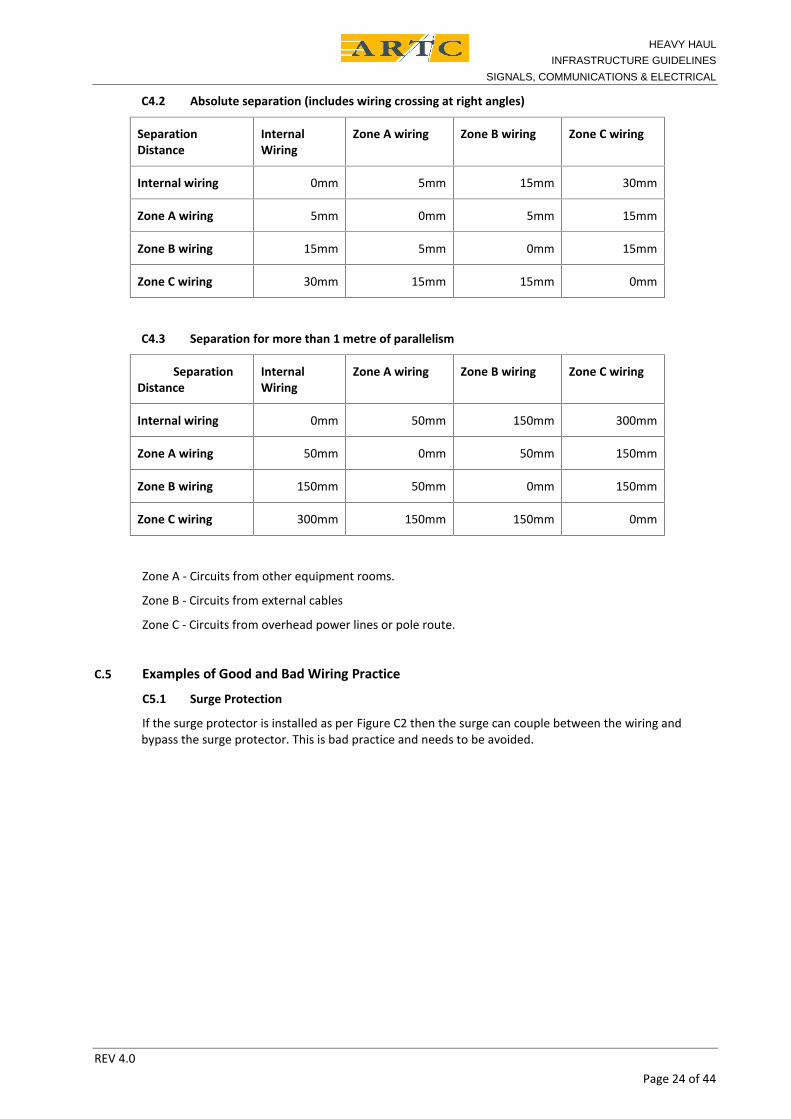
If the surge protector is installed as per Figure C2 then the surge can couple between the wiring andbypass the surge protector. This is bad practice and needs to be avoided.
HEAVY HAULINFRASTRUCTURE GUIDELINES
SIGNALS, COMMUNICATIONS & ELECTRICAL
REV 4.0Page 25 of 44
FigureC2 – Bad Wiring Practice for Surge Protection
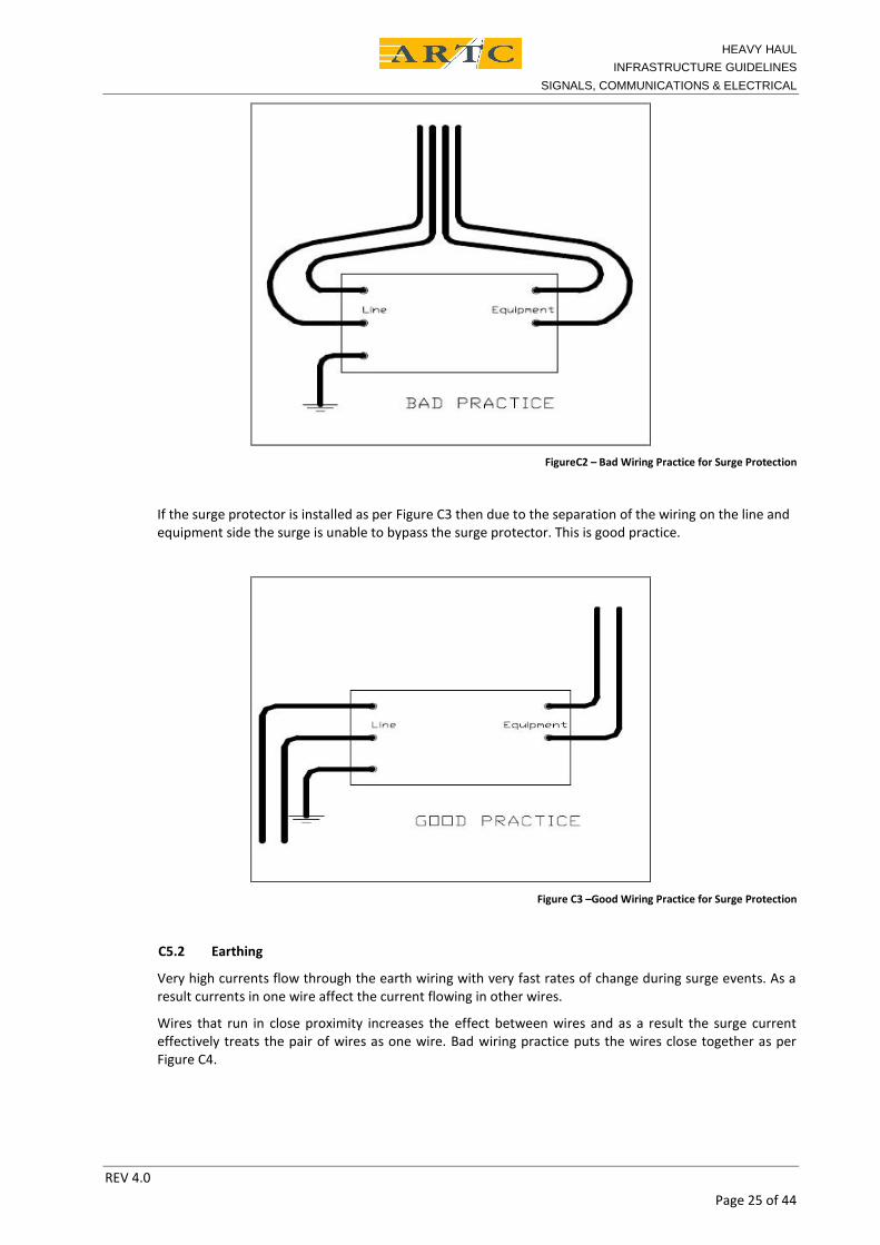
If the surge protector is installed as per Figure C3 then due to the separation of the wiring on the line andequipment side the surge is unable to bypass the surge protector. This is good practice.
Figure C3 –Good Wiring Practice for Surge Protection
C5.2 Earthing
Very high currents flow through the earth wiring with very fast rates of change during surge events. As aresult currents in one wire affect the current flowing in other wires.
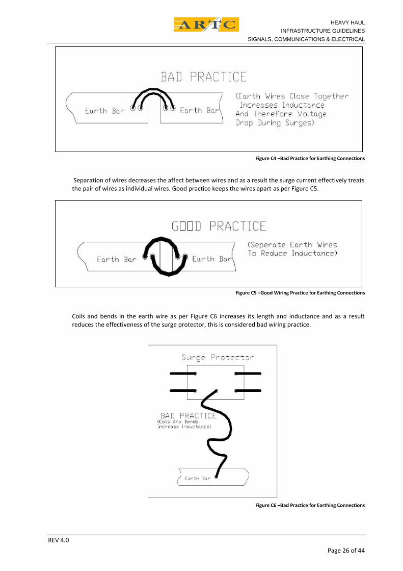
Wires that run in close proximity increases the effect between wires and as a result the surge currenteffectively treats the pair of wires as one wire. Bad wiring practice puts the wires close together as perFigure C4.
HEAVY HAULINFRASTRUCTURE GUIDELINES
SIGNALS, COMMUNICATIONS & ELECTRICAL
REV 4.0Page 26 of 44
Figure C4 –Bad Practice for Earthing Connections
Separation of wires decreases the affect between wires and as a result the surge current effectively treatsthe pair of wires as individual wires. Good practice keeps the wires apart as per Figure C5.
Figure C5 –Good Wiring Practice for Earthing Connections
Coils and bends in the earth wire as per Figure C6 increases its length and inductance and as a resultreduces the effectiveness of the surge protector, this is considered bad wiring practice.
Figure C6 –Bad Practice for Earthing Connections
HEAVY HAULINFRASTRUCTURE GUIDELINES
SIGNALS, COMMUNICATIONS & ELECTRICAL
REV 4.0Page 27 of 44
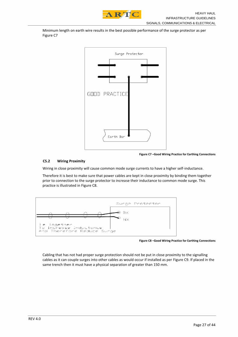
Minimum length on earth wire results in the best possible performance of the surge protector as perFigure C7
Figure C7 –Good Wiring Practice for Earthing Connections
C5.2 Wiring Proximity
Wiring in close proximity will cause common mode surge currents to have a higher self-inductance.
Therefore it is best to make sure that power cables are kept in close proximity by binding them togetherprior to connection to the surge protector to increase their inductance to common mode surge. Thispractice is illustrated in Figure C8.
Figure C8 –Good Wiring Practice for Earthing Connections
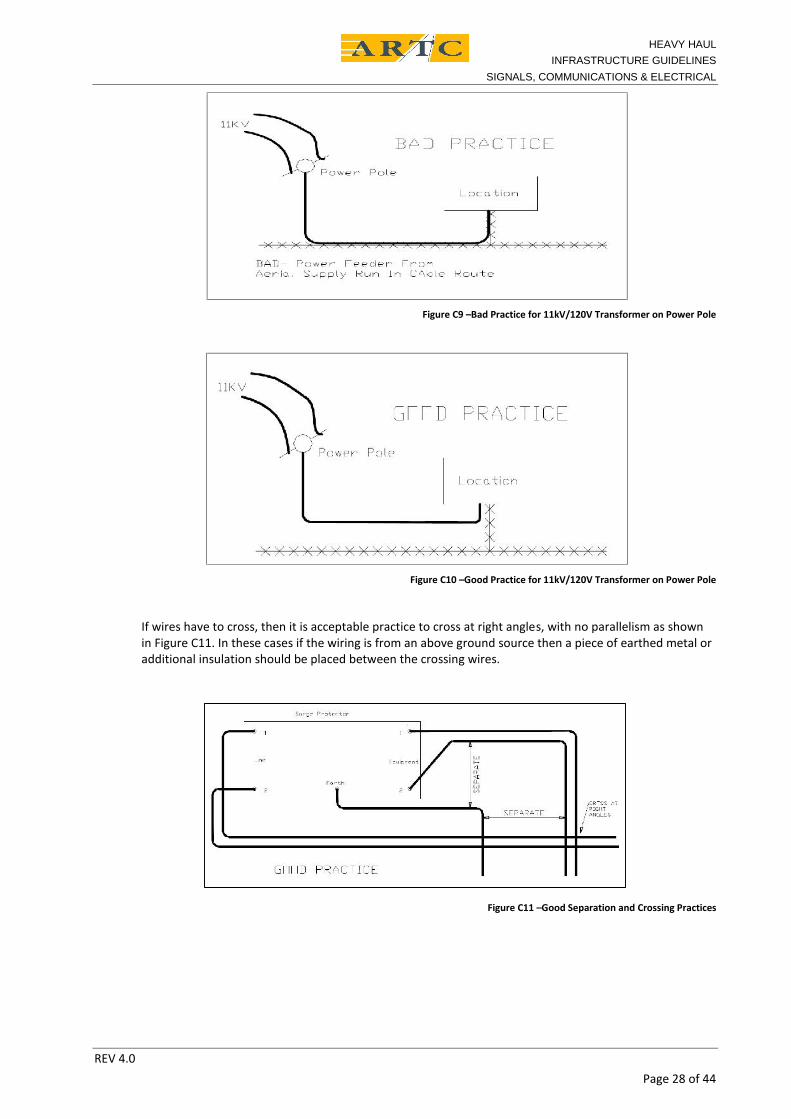
Cabling that has not had proper surge protection should not be put in close proximity to the signallingcables as it can couple surges into other cables as would occur if installed as per Figure C9. If placed in thesame trench then it must have a physical separation of greater than 150 mm.
HEAVY HAULINFRASTRUCTURE GUIDELINES
SIGNALS, COMMUNICATIONS & ELECTRICAL
REV 4.0Page 28 of 44
Figure C9 –Bad Practice for 11kV/120V Transformer on Power Pole
Figure C10 –Good Practice for 11kV/120V Transformer on Power Pole
If wires have to cross, then it is acceptable practice to cross at right angles, with no parallelism as shownin Figure C11. In these cases if the wiring is from an above ground source then a piece of earthed metal oradditional insulation should be placed between the crossing wires.
Figure C11 –Good Separation and Crossing Practices
HEAVY HAULINFRASTRUCTURE GUIDELINES
SIGNALS, COMMUNICATIONS & ELECTRICAL
REV 4.0Page 29 of 44
C.6 Preferred Practice for Wiring
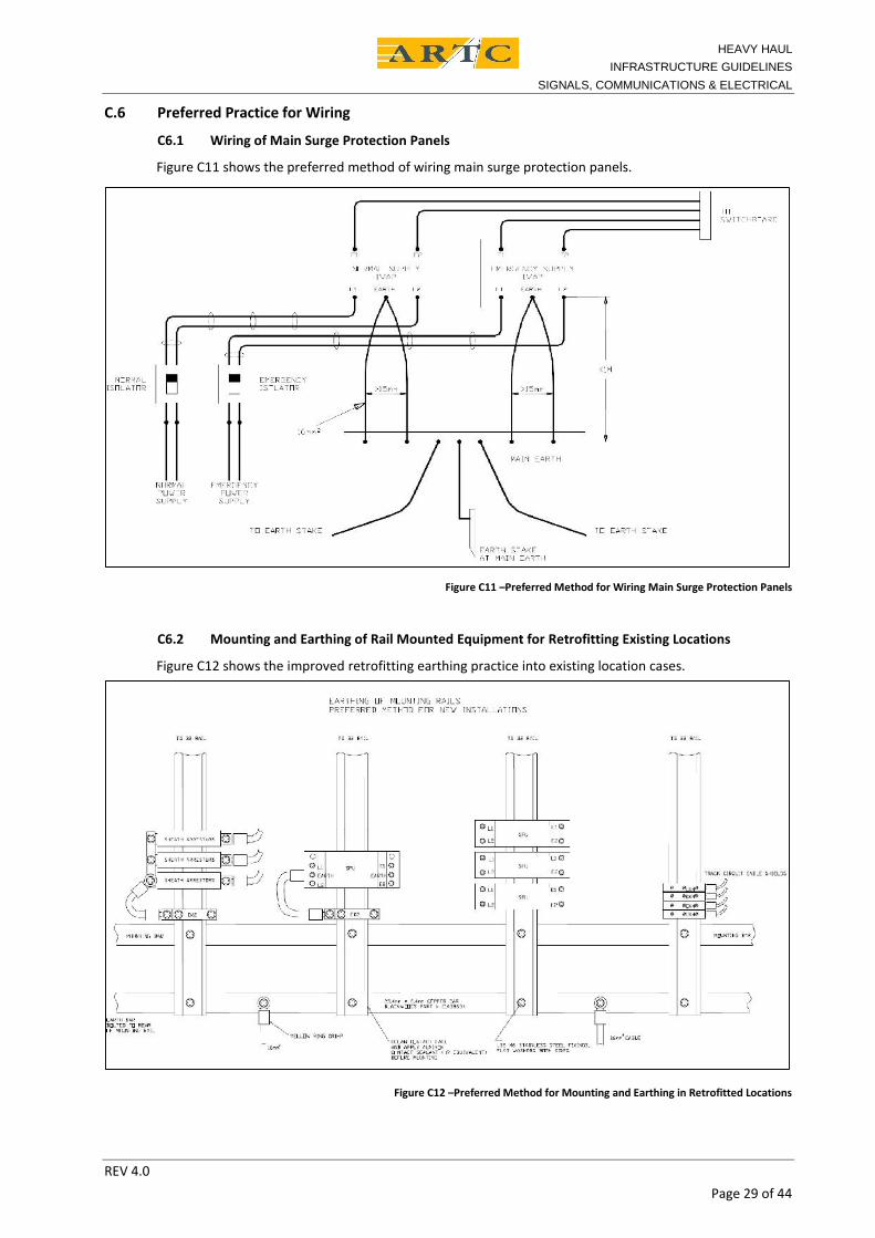
C6.1 Wiring of Main Surge Protection Panels
Figure C11 shows the preferred method of wiring main surge protection panels.
Figure C11 –Preferred Method for Wiring Main Surge Protection Panels
C6.2 Mounting and Earthing of Rail Mounted Equipment for Retrofitting Existing Locations
Figure C12 shows the improved retrofitting earthing practice into existing location cases.
Figure C12 –Preferred Method for Mounting and Earthing in Retrofitted Locations
HEAVY HAULINFRASTRUCTURE GUIDELINES
SIGNALS, COMMUNICATIONS & ELECTRICAL
REV 4.0Page 30 of 44
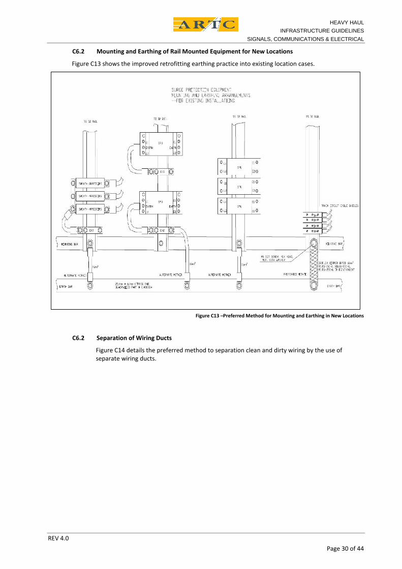
C6.2 Mounting and Earthing of Rail Mounted Equipment for New Locations
Figure C13 shows the improved retrofitting earthing practice into existing location cases.
Figure C13 –Preferred Method for Mounting and Earthing in New Locations
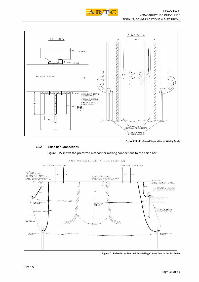
C6.2 Separation of Wiring Ducts
Figure C14 details the preferred method to separation clean and dirty wiring by the use ofseparate wiring ducts.
HEAVY HAULINFRASTRUCTURE GUIDELINES
SIGNALS, COMMUNICATIONS & ELECTRICAL
REV 4.0Page 31 of 44
Figure C14 –Preferred Separation of Wiring Ducts
C6.2 Earth Bar Connections
Figure C15 shows the preferred method for making connections to the earth bar
Figure C15 –Preferred Method for Making Connection to the Earth Bar

HEAVY HAULINFRASTRUCTURE GUIDELINES
SIGNALS, COMMUNICATIONS & ELECTRICAL
REV 4.0Page 32 of 44
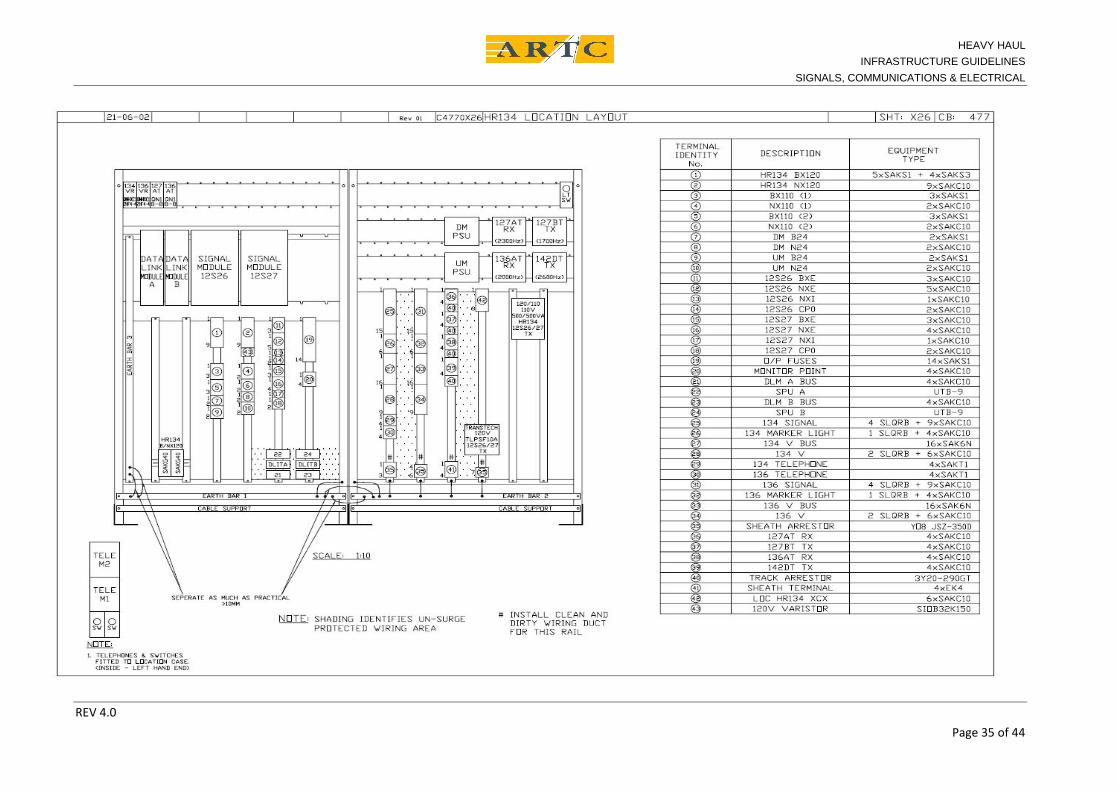
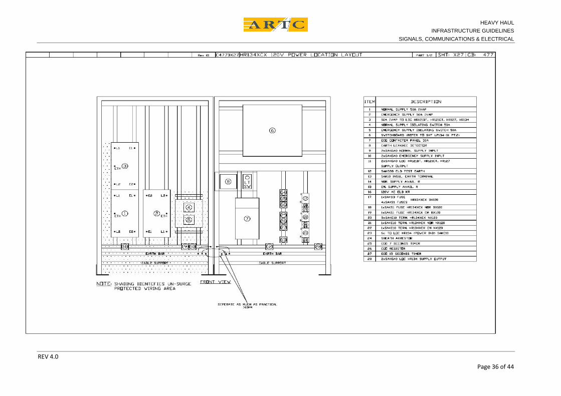
C.7 Location Layout Example
Attached drawing CB:477 Sheet X27 Part 1 of 2 shows a Power Supply location layout. Cableentry is from the bottom of the location.This drawing shows:
The earth bars being bonded in series because the length of the bond is short. The earth bars being bonded to the location metalwork. The dotted shading area around the IVAP surge panels indicates the area where the non-
surge protected wiring is to be run and surge protected wiring must not be run.
The IVAP surge panels have been mounted low in the location to reduce the length earthwires to the earth bar.
The IVAP surge panel 2 has been turned around to allow separation of the protected and un-protected wiring.
The IVAP surge panel 3 is mounted higher in the location because of physical constraints andpanels 1, and 2 are the primary power supply surge protection.
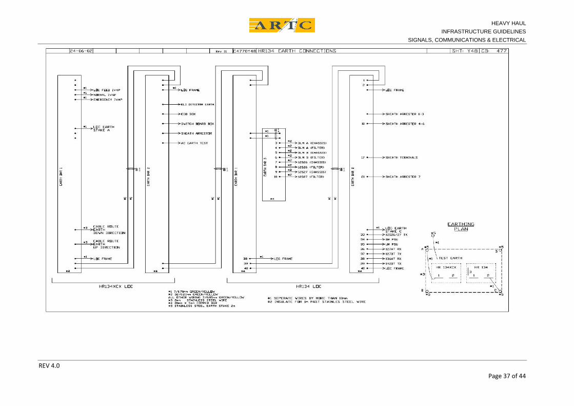
C.8 Earthing Plan Example
Attached drawing CB:477 sheet Y48 HR134 Earth Connections shows the earth connections for aPower supply location with SSI type CBI equipment.A High voltage earth exists near the location but is separated from the signalling earth by morethan 17 metres.A Council MEN earth exists near the location but is separated from the signalling earth by morethan 2 m.These earths are not shown on the drawing because they meet the separation requirements. Ifthey did not meet the separation requirements then they would be shown on the plan.The drawing shows:
The earth bars installed How the earth bars are interconnected. Where the equipment earths are connected. The earth stakes installed, where they are located, and how they are connected.
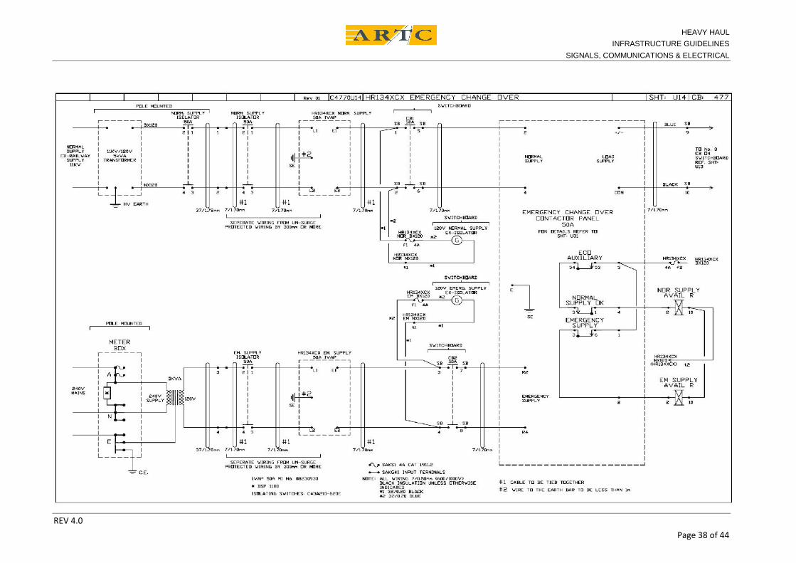
C.9 AC Power Supply Circuit ExampleAttached drawing CB:477 sheet U14 shows the circuit for wiring to the emergency Change-overcontactor.The drawing shows: Notes indicating the unprotected wiring that must be separated from surge protected wiring.
Notes indicating the wiring the must be cable tied together to improve surge protectionperformance. The cable ties are not necessary if a twin or twisted pair cable is used.
Notes detailing the limits for the length of the IVAP earth connections.
A surge protector at Council supply metre box to limit surges in cabling to location.
C.10 Examples of Good and Poor Installation Practice
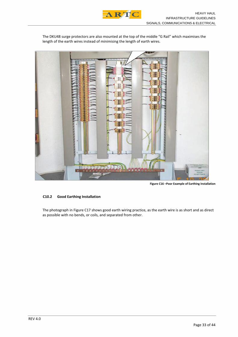
C10.1 Poor Earthing Installation
The photograph in Figure C16 shows poor earth wiring practice because the wiring:
Is not as short as practical, Has bends which are un-necessary, Is mixed with surge protected wiring.
HEAVY HAULINFRASTRUCTURE GUIDELINES
SIGNALS, COMMUNICATIONS & ELECTRICAL
REV 4.0Page 33 of 44
The DKU48 surge protectors are also mounted at the top of the middle “G Rail” which maximises thelength of the earth wires instead of minimising the length of earth wires.
Figure C16 –Poor Example of Earthing Installation
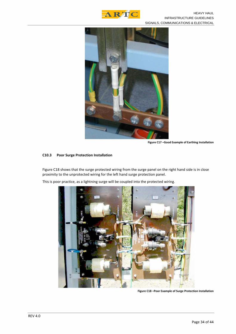
C10.2 Good Earthing Installation
The photograph in Figure C17 shows good earth wiring practice, as the earth wire is as short and as directas possible with no bends, or coils, and separated from other.
HEAVY HAULINFRASTRUCTURE GUIDELINES
SIGNALS, COMMUNICATIONS & ELECTRICAL
REV 4.0Page 34 of 44
Figure C17 –Good Example of Earthing Installation
C10.3 Poor Surge Protection Installation
Figure C18 shows that the surge protected wiring from the surge panel on the right hand side is in closeproximity to the unprotected wiring for the left hand surge protection panel.
This is poor practice, as a lightning surge will be coupled into the protected wiring.
Figure C18 –Poor Example of Surge Protection Installation
HEAVY HAULINFRASTRUCTURE GUIDELINES
SIGNALS, COMMUNICATIONS & ELECTRICAL
REV 4.0Page 35 of 44
HEAVY HAULINFRASTRUCTURE GUIDELINES
SIGNALS, COMMUNICATIONS & ELECTRICAL
REV 4.0Page 36 of 44
HEAVY HAULINFRASTRUCTURE GUIDELINES
SIGNALS, COMMUNICATIONS & ELECTRICAL
REV 4.0Page 37 of 44
HEAVY HAULINFRASTRUCTURE GUIDELINES
SIGNALS, COMMUNICATIONS & ELECTRICAL
REV 4.0Page 38 of 44
HEAVY HAULINFRASTRUCTURE GUIDELINES
SIGNALS, COMMUNICATIONS & ELECTRICAL
REV 4.0Page 39 of 44
Appendix D Switch Identification and ESML/EOL Signage
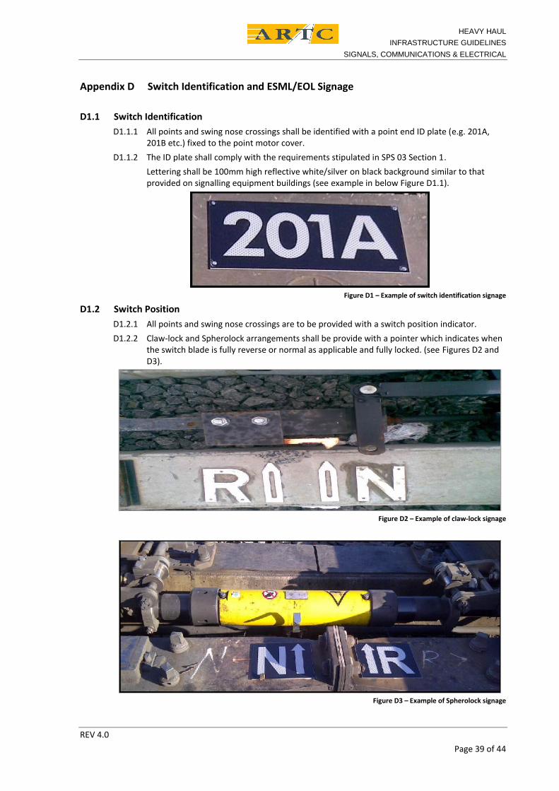
D1.1 Switch IdentificationD1.1.1 All points and swing nose crossings shall be identified with a point end ID plate (e.g. 201A,
201B etc.) fixed to the point motor cover.D1.1.2 The ID plate shall comply with the requirements stipulated in SPS 03 Section 1.
Lettering shall be 100mm high reflective white/silver on black background similar to thatprovided on signalling equipment buildings (see example in below Figure D1.1).
Figure D1 – Example of switch identification signage
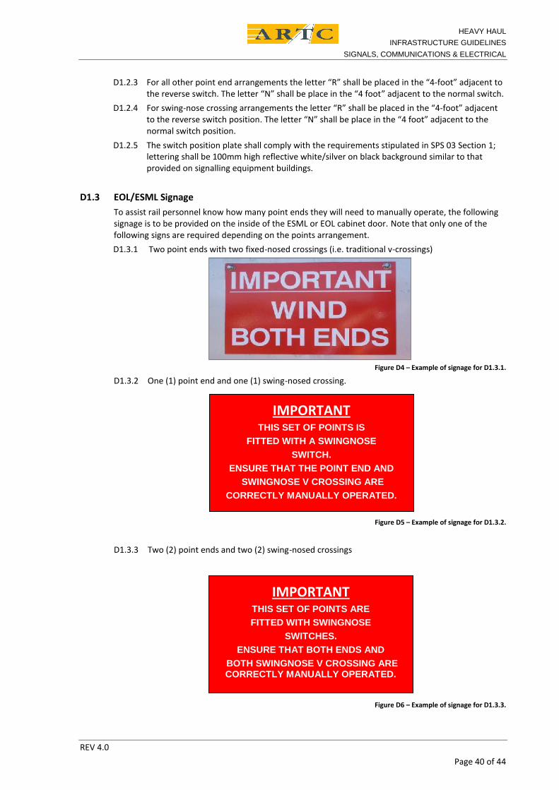
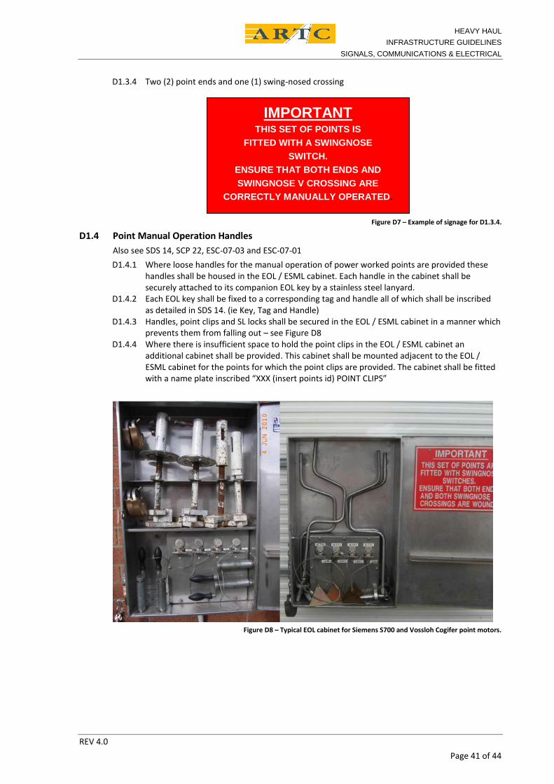
D1.2 Switch PositionD1.2.1 All points and swing nose crossings are to be provided with a switch position indicator.D1.2.2 Claw-lock and Spherolock arrangements shall be provide with a pointer which indicates when
the switch blade is fully reverse or normal as applicable and fully locked. (see Figures D2 andD3).
Figure D2 – Example of claw-lock signage
Figure D3 – Example of Spherolock signage
HEAVY HAULINFRASTRUCTURE GUIDELINES
SIGNALS, COMMUNICATIONS & ELECTRICAL
REV 4.0Page 40 of 44
D1.2.3 For all other point end arrangements the letter “R” shall be placed in the “4-foot” adjacent tothe reverse switch. The letter “N” shall be place in the “4 foot” adjacent to the normal switch.
D1.2.4 For swing-nose crossing arrangements the letter “R” shall be placed in the “4-foot” adjacentto the reverse switch position. The letter “N” shall be place in the “4 foot” adjacent to thenormal switch position.
D1.2.5 The switch position plate shall comply with the requirements stipulated in SPS 03 Section 1;lettering shall be 100mm high reflective white/silver on black background similar to thatprovided on signalling equipment buildings.
D1.3 EOL/ESML SignageTo assist rail personnel know how many point ends they will need to manually operate, the followingsignage is to be provided on the inside of the ESML or EOL cabinet door. Note that only one of thefollowing signs are required depending on the points arrangement.D1.3.1 Two point ends with two fixed-nosed crossings (i.e. traditional v-crossings)
Figure D4 – Example of signage for D1.3.1.
D1.3.2 One (1) point end and one (1) swing-nosed crossing.
Figure D5 – Example of signage for D1.3.2.
D1.3.3 Two (2) point ends and two (2) swing-nosed crossings
THIS SET OF POINTS IS
Figure D6 – Example of signage for D1.3.3.
IMPORTANTTHIS SET OF POINTS AREFITTED WITH SWINGNOSE
SWITCHES.ENSURE THAT BOTH ENDS AND
BOTH SWINGNOSE V CROSSING ARECORRECTLY MANUALLY OPERATED.
IMPORTANTTHIS SET OF POINTS IS
FITTED WITH A SWINGNOSESWITCH.
ENSURE THAT THE POINT END ANDSWINGNOSE V CROSSING ARE
CORRECTLY MANUALLY OPERATED.
HEAVY HAULINFRASTRUCTURE GUIDELINES
SIGNALS, COMMUNICATIONS & ELECTRICAL
REV 4.0Page 41 of 44
D1.3.4 Two (2) point ends and one (1) swing-nosed crossing
crossing
Figure D7 – Example of signage for D1.3.4.
D1.4 Point Manual Operation HandlesAlso see SDS 14, SCP 22, ESC-07-03 and ESC-07-01D1.4.1 Where loose handles for the manual operation of power worked points are provided these
handles shall be housed in the EOL / ESML cabinet. Each handle in the cabinet shall besecurely attached to its companion EOL key by a stainless steel lanyard.
D1.4.2 Each EOL key shall be fixed to a corresponding tag and handle all of which shall be inscribedas detailed in SDS 14. (ie Key, Tag and Handle)
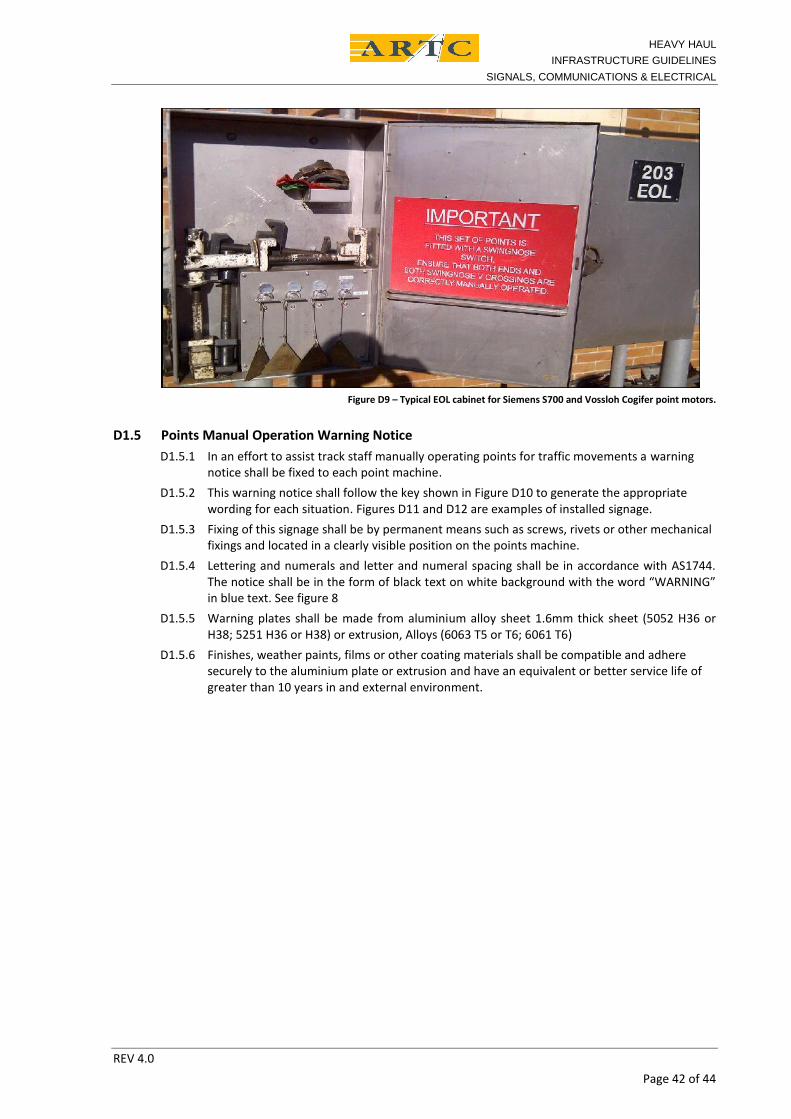
D1.4.3 Handles, point clips and SL locks shall be secured in the EOL / ESML cabinet in a manner whichprevents them from falling out – see Figure D8
D1.4.4 Where there is insufficient space to hold the point clips in the EOL / ESML cabinet anadditional cabinet shall be provided. This cabinet shall be mounted adjacent to the EOL /ESML cabinet for the points for which the point clips are provided. The cabinet shall be fittedwith a name plate inscribed “XXX (insert points id) POINT CLIPS”
Figure D8 – Typical EOL cabinet for Siemens S700 and Vossloh Cogifer point motors.
IMPORTANTTHIS SET OF POINTS IS
FITTED WITH A SWINGNOSESWITCH.
ENSURE THAT BOTH ENDS ANDSWINGNOSE V CROSSING ARE
CORRECTLY MANUALLY OPERATED.
HEAVY HAULINFRASTRUCTURE GUIDELINES
SIGNALS, COMMUNICATIONS & ELECTRICAL
REV 4.0Page 42 of 44
Figure D9 – Typical EOL cabinet for Siemens S700 and Vossloh Cogifer point motors.
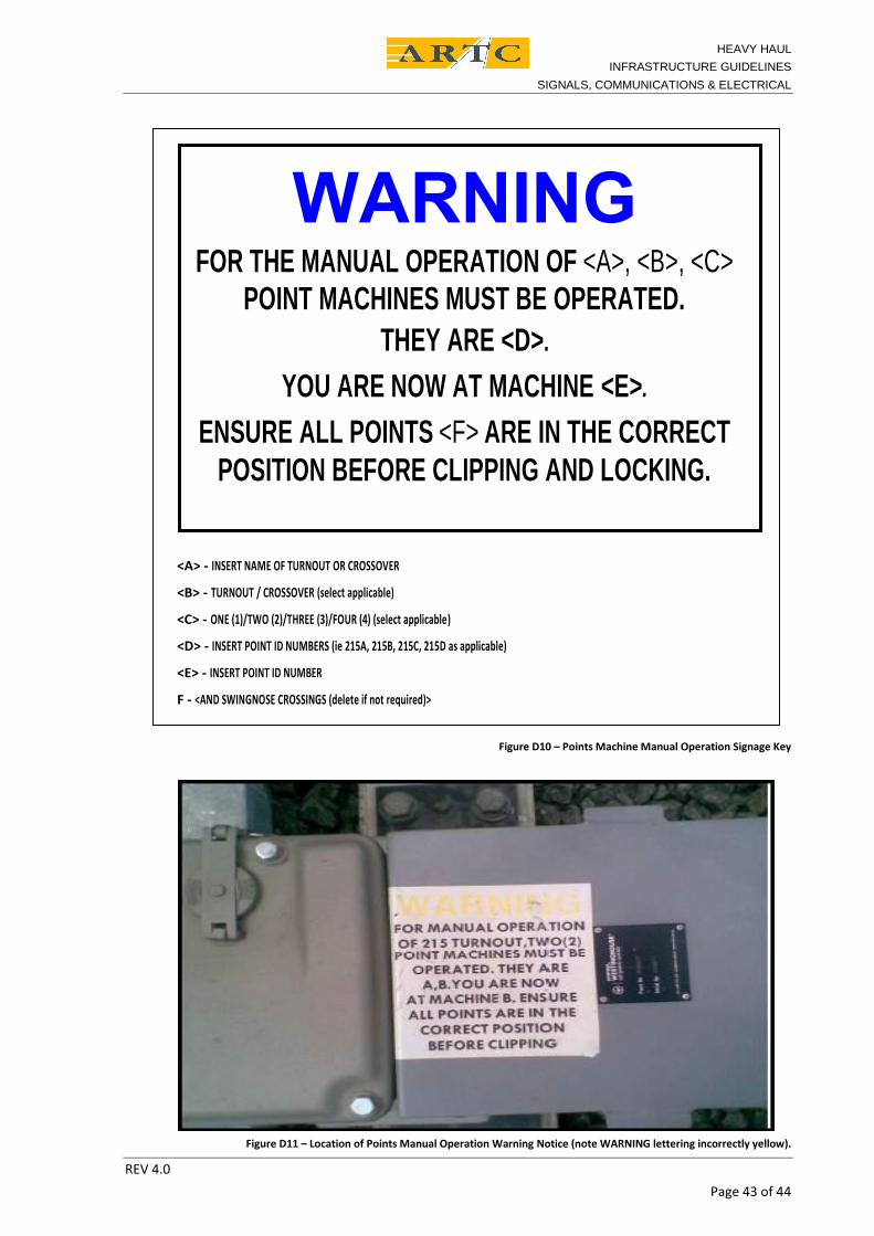
D1.5 Points Manual Operation Warning NoticeD1.5.1 In an effort to assist track staff manually operating points for traffic movements a warning
notice shall be fixed to each point machine.D1.5.2 This warning notice shall follow the key shown in Figure D10 to generate the appropriate
wording for each situation. Figures D11 and D12 are examples of installed signage.D1.5.3 Fixing of this signage shall be by permanent means such as screws, rivets or other mechanical
fixings and located in a clearly visible position on the points machine.D1.5.4 Lettering and numerals and letter and numeral spacing shall be in accordance with AS1744.
The notice shall be in the form of black text on white background with the word “WARNING”in blue text. See figure 8
D1.5.5 Warning plates shall be made from aluminium alloy sheet 1.6mm thick sheet (5052 H36 orH38; 5251 H36 or H38) or extrusion, Alloys (6063 T5 or T6; 6061 T6)
D1.5.6 Finishes, weather paints, films or other coating materials shall be compatible and adheresecurely to the aluminium plate or extrusion and have an equivalent or better service life ofgreater than 10 years in and external environment.
HEAVY HAULINFRASTRUCTURE GUIDELINES
SIGNALS, COMMUNICATIONS & ELECTRICAL
REV 4.0Page 43 of 44
WARNINGFOR THE MANUAL OPERATION OF <A>, <B>, <C>
POINT MACHINES MUST BE OPERATED.THEY ARE <D>.
YOU ARE NOW AT MACHINE <E>.ENSURE ALL POINTS <F> ARE IN THE CORRECT
POSITION BEFORE CLIPPING AND LOCKING.
<A> - INSERT NAME OF TURNOUT OR CROSSOVER
<B> - TURNOUT / CROSSOVER (select applicable)
<C> - ONE (1)/TWO (2)/THREE (3)/FOUR (4) (select applicable)
<D> - INSERT POINT ID NUMBERS (ie 215A, 215B, 215C, 215D as applicable)
<E> - INSERT POINT ID NUMBER
F - <AND SWINGNOSE CROSSINGS (delete if not required)>
Figure D10 – Points Machine Manual Operation Signage Key
Figure D11 – Location of Points Manual Operation Warning Notice (note WARNING lettering incorrectly yellow).
HEAVY HAULINFRASTRUCTURE GUIDELINES
SIGNALS, COMMUNICATIONS & ELECTRICAL
REV 4.0Page 44 of 44
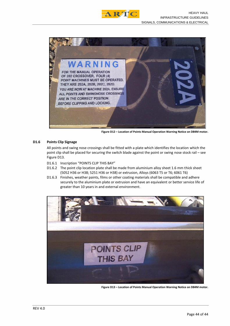
Figure D12 – Location of Points Manual Operation Warning Notice on D84M motor.
D1.6 Points Clip SignageAll points and swing nose crossings shall be fitted with a plate which identifies the location which thepoint clip shall be placed for securing the switch blade against the point or swing nose stock rail – seeFigure D13.D1.6.1 Inscription “POINTS CLIP THIS BAY”D1.6.2 The point clip location plate shall be made from aluminium alloy sheet 1.6 mm thick sheet
(5052 H36 or H38; 5251 H36 or H38) or extrusion, Alloys (6063 T5 or T6; 6061 T6)D1.6.3 Finishes, weather paints, films or other coating materials shall be compatible and adhere
securely to the aluminium plate or extrusion and have an equivalent or better service life ofgreater than 10 years in and external environment.
Figure D13 – Location of Points Manual Operation Warning Notice on D84M motor.