heavy duty grip strut grating load table of contents ... · heavy duty grip strut grating load...
TRANSCRIPT
Eaton’s B-Line series safety gratings www.eaton.com/b-lineseries 62
Heavy D
uty
Grip
Stru
t Gratin
g
Heavy Duty Grip Strut Grating Load Table of Contents - Advantages
AdvantagesGratings for greater loads, safer walking• High strength-to-weight ratio — efficient structural design
means large-load capacity with low deadweight
• Slip resisting surface — scores of tiny teeth grip shoes tightly (exceeds Federal Specification RR-G-1602D slip-resistance requirements)
• Open design — sheds slip-causing stones, dirt and debris
• Slip-resisting serrated or less harsh non-serrated wearing surfaces tailor long life to diverse service conditions — sheds slip-causing stones, dirt and debris
• Complete line of products, design data, support services
• Handrail brackets available for maximum safety and meeting OSHA requirements
• Splice plates speed assembly without welding
• Integral, OSHA compliant toeboards. Canadian compliant OH&S designs available in some sizes.
Heavy Duty Grip Strut walkwayHelps provide safer
walking surface
Heavy Duty Grip Strut pattern- No teeth -
Labor saving alternative to bar grating lowest installed solution
Heavy Duty Grip Strut pattern- Standard with teeth -
cleaning and self draining all-in-one
Heavy Duty Grip Strut Walkway-Reduced opening -
Limits items from falling through openings for safety below
Heavy Duty Grip Strut™ Design Load Tables
Steel
2-Diamond planks - 91/4" width . . . . . . . . . . . . . . . 68 - 69 3-Diamond planks - 133/4" width . . . . . . . . . . . . . . 70 - 71 5-Diamond planks - 231/4" width . . . . . . . . . . . . . . 72 - 73 6-Diamond planks - 273/4" width . . . . . . . . . . . . . . 74 - 75 8-Diamond planks - 36" width . . . . . . . . . . . . . . . 76 - 77
Eaton’s B-Line series safety gratings www.eaton.com/b-lineseries 63
Hea
vy D
uty
G
rip
Str
ut
Gra
tin
g
Heavy Duty Grip Strut Grating - Advantages
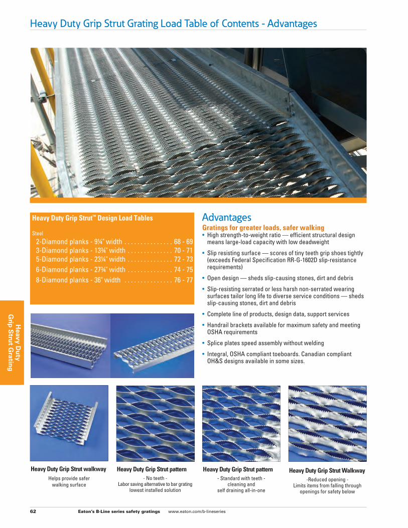
Heavy Duty Grip Strut overviewEvery year, falls cost industry millions of dollars in lost time and production. The safer walking-working surfaces of Heavy Duty Grip Strut™ safety grating products help reduce accidents, and in doing so, may help cut insurance costs.
The secret is in the serrated surface and open design. The open diamond pattern allows fluids, mud, chips, ice and snow to fall through. The serrated surface helps provide high friction for maximum slip protection in all directions, and under practically all conditions. The resilience of Grip Strut grating cushions the impact of walking, lessening worker fatigue and increasing efficiency.
Heavy Duty Grip Strut safety grating products offer the advantage of regular Grip Strut safety grating, but are designed for applications of greater load and/or longer span. Basic design is the same, but diamond openings are larger and metal is thicker. Heavy Duty grating products are available in many of the same configurations, materials and finishes as regular Grip Strut safety grating. Heavy Duty Grip Strut grating products include: planks, walkways and stair treads; for specification see pages 84 & 85. For specifications and information on regular Grip Strut safety gratings, see pages 28-29.
High load capacity, long life • High strength-to-weight performance is achieved through
section depth and integral side-channel design.
• Bridged struts form a rigid, strong plank surface that carries large loads with minimum deflection.
• No rivets, fabricated joints or pressure joints to loosen or break.
Safety at all levels • Serrated surfaces grip soles securely in all directions.
• Non-slip sheared edges are ideal for both indoor and outdoor locations — wherever mud, ice, snow, oil and detergents can create hazardous walking conditions.
Minimal maintenance • Openings allow fluids, chips, stones and mud to quickly
drop through. Ice easily shears off under normal foot pressure.
• Open design is easily cleaned with a brush, liquid or air spray.
Application versatility • Variety of standard plank widths and channel heights can
be combined with numerous special-order items to meet almost any application requirement.
• Special sizes and fabricating services are available for unusual requirements.
• May be painted, hot-dip galvanized after fabrication, anodized, plated, plastic-coated or specially finished in other ways to fit service requirements.
• Finish coatings are economically applied since all surfaces are accessible to brush or spray.
Compliance with regulatory codes / standards • Exceeds Federal Specification RR-G-1602D requirements.
• Meets OSHA toeboard requirements for elevated structures with standard upturned, 5 inch high integral side channels.
Low life-cycle cost • Lower upfront material costs and long-lasting, corrosion-
resisting finishes help provide long service life to all Grip Strut gratings: steel or aluminum.
• Brawny yet lightweight, these planks, walkways and stair treads permit substantial reduction in supporting structural materials.
• Self-cleaning open design is virtually maintenance-free.
Fast, simple Installation • Light and simply installed.
• Regular maintenance personnel can do the job.
• Sections are easily field-cut, at virtually any angle, and field-adapted; connections are rapidly made with bolts, clamps or welding.
• Disassembly, when needed, can be just as rapid.
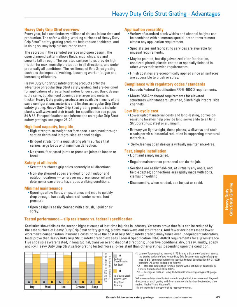
(1) Value of force required to move 1 175 lb. load a distance of one inch across the grating surface of two Heavy-Duty Grip Strut serrated style safety grat-ings (B & C) compared with the respective Federal Specification RR-G-1602D standard (A). Letter coding is as follows:
* A — standard established for steel grating with each type of condition, by Federal Specification RR-G-1602D.
* B — average of tests on Heavy Duty Grip Strut safety gratings of 10 gauge steel.
Values were determined by test made in longitudinal, transverse and diagonal directions on each grating with five sole materials: leather, boot rubber, shoe rubber, Neolite®† and Hypaton®†.† Mark shown is the property of its respective owner.
Tested performance – slip resistance vs. federal specification
Statistics show falls as the second highest cause of lost-time injuries in industry. Yet tests prove that falls can be reduced by the safe surface of Heavy Duty Grip Strut safety grating, planks, walkways and stair treads. And fewer accidents mean lower workmen’s compensation insurance costs, to save the cost of Grip Strut safety grating many times over. Independent laboratory tests prove that Heavy Duty Grip Strut safety grating exceeds Federal Specification RR-G-1602D requirements for slip resistance. Five shoe soles were tested, in longitudinal, transverse and diagonal directions; under five conditions: dry, greasy, muddy, soapy and icy. Heavy Duty Grip Strut safety grating tested more slip-resistant than other gratings (depending upon the condition).
AFederal Specification for Steel
B
10 Gauge Steel Heavy-Duty Grip Strut Grating
1501401301201101009080706050
Po
un
ds
of
Fo
rce
A B A B A B A B A B
Dry Mud Ice Grease Soap
Eaton’s B-Line series safety gratings www.eaton.com/b-lineseries 64
Heavy D
uty
Grip
Stru
t Gratin
g
Heavy Duty Grip Strut Grating - General Load InformationWalkways, Planks and Stair Treads
General load informationHeavy Duty Grip Strut™ safety grating walkways and planks are available in three thicknesses of steel and one of aluminum; walkways have one standard siderail height, planks have four. In each category, walkways come in three widths, planks in five. Begin sizing, for maximum economy, with widest practical grating for the job (shallowest siderails and thinnest gauge); if this does not meet required load capacity, first consider deeper siderails, then heavier gauge, and finally narrower grating width, if necessary.
Flexural load tables have been calculated according to design load limiting criteria, and if not illustrated in this catalog they can be obtained from our technical services.
“Strut Load Tables” show flexural strength and deflection of individual grating surface struts relative to siderails. Since these are maximum values in the elastic range, lesser loads and deflections can be proportioned from them.
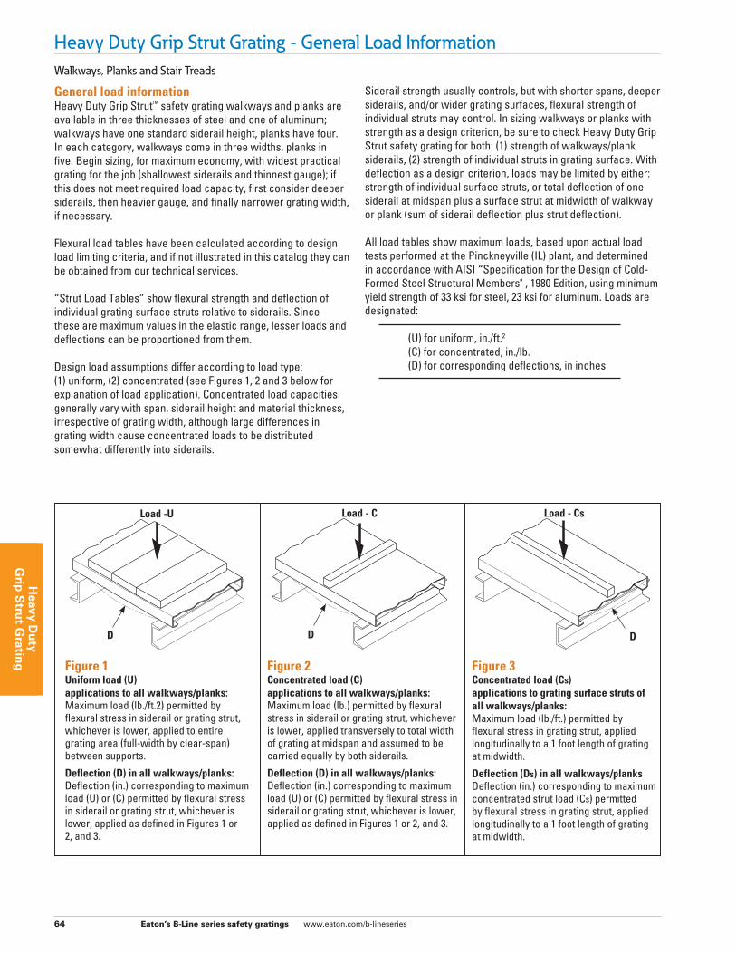
Design load assumptions differ according to load type: (1) uniform, (2) concentrated (see Figures 1, 2 and 3 below for explanation of load application). Concentrated load capacities generally vary with span, siderail height and material thickness, irrespective of grating width, although large differences in grating width cause concentrated loads to be distributed somewhat differently into siderails.
Siderail strength usually controls, but with shorter spans, deeper siderails, and/or wider grating surfaces, flexural strength of individual struts may control. In sizing walkways or planks with strength as a design criterion, be sure to check Heavy Duty Grip Strut safety grating for both: (1) strength of walkways/plank siderails, (2) strength of individual struts in grating surface. With deflection as a design criterion, loads may be limited by either: strength of individual surface struts, or total deflection of one siderail at midspan plus a surface strut at midwidth of walkway or plank (sum of siderail deflection plus strut deflection).
All load tables show maximum loads, based upon actual load tests performed at the Pinckneyville (IL) plant, and determined in accordance with AISI “Specification for the Design of Cold-Formed Steel Structural Members" , 1980 Edition, using minimum yield strength of 33 ksi for steel, 23 ksi for aluminum. Loads are designated: (U) for uniform, in./ft.2
(C) for concentrated, in./lb. (D) for corresponding deflections, in inches
Figure 1Uniform load (U) applications to all walkways/planks:Maximum load (lb./ft.2) permitted by flexural stress in siderail or grating strut, whichever is lower, applied to entire grating area (full-width by clear-span) between supports.
Deflection (D) in all walkways/planks:Deflection (in.) corresponding to maximum load (U) or (C) permitted by flexural stress in siderail or grating strut, whichever is lower, applied as defined in Figures 1 or 2, and 3.
Figure 2Concentrated load (C) applications to all walkways/planks:Maximum load (lb.) permitted by flexural stress in siderail or grating strut, whichever is lower, applied transversely to total width of grating at midspan and assumed to be carried equally by both siderails.
Deflection (D) in all walkways/planks:Deflection (in.) corresponding to maximum load (U) or (C) permitted by flexural stress in siderail or grating strut, whichever is lower, applied as defined in Figures 1 or 2, and 3.
Figure 3Concentrated load (Cs) applications to grating surface struts of all walkways/planks:Maximum load (lb./ft.) permitted by flexural stress in grating strut, applied longitudinally to a 1 foot length of grating at midwidth.
Deflection (Ds) in all walkways/planksDeflection (in.) corresponding to maximum concentrated strut load (Cs) permitted by flexural stress in grating strut, applied longitudinally to a 1 foot length of grating at midwidth.
D
Load -U
D D
Load - C Load - Cs
Eaton’s B-Line series safety gratings www.eaton.com/b-lineseries 65
Hea
vy D
uty
G
rip
Str
ut
Gra
tin
g
Heavy Duty Grip Strut Grating - General Load InformationWalkways with Integrated Toeboards, Meeting OSHA Requirements
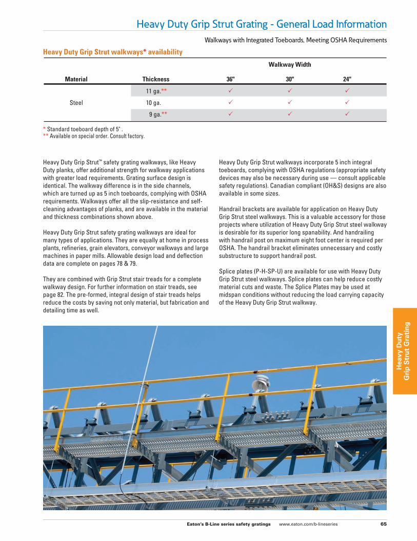
Heavy Duty Grip Strut™ safety grating walkways, like Heavy Duty planks, offer additional strength for walkway applications with greater load requirements. Grating surface design is identical. The walkway difference is in the side channels, which are turned up as 5 inch toeboards, complying with OSHA requirements. Walkways offer all the slip-resistance and self-cleaning advantages of planks, and are available in the material and thickness combinations shown above.
Heavy Duty Grip Strut safety grating walkways are ideal for many types of applications. They are equally at home in process plants, refineries, grain elevators, conveyor walkways and large machines in paper mills. Allowable design load and deflection data are complete on pages 78 & 79.
They are combined with Grip Strut stair treads for a complete walkway design. For further information on stair treads, see page 82. The pre-formed, integral design of stair treads helps reduce the costs by saving not only material, but fabrication and detailing time as well.
Heavy Duty Grip Strut walkways incorporate 5 inch integral toeboards, complying with OSHA regulations (appropriate safety devices may also be necessary during use — consult applicable safety regulations). Canadian compliant (OH&S) designs are also available in some sizes.
Handrail brackets are available for application on Heavy Duty Grip Strut steel walkways. This is a valuable accessory for those projects where utilization of Heavy Duty Grip Strut steel walkway is desirable for its superior long spanability. And handrailing with handrail post on maximum eight foot center is required per OSHA. The handrail bracket eliminates unnecessary and costly substructure to support handrail post.
Splice plates (P-H-SP-U) are available for use with Heavy Duty Grip Strut steel walkways. Splice plates can help reduce costly material cuts and waste. The Splice Plates may be used at midspan conditions without reducing the load carrying capacity of the Heavy Duty Grip Strut walkway.
Heavy Duty Grip Strut walkways* availability
Walkway Width
Material Thickness 36" 30" 24"
11 ga.** P P P
Steel 10 ga. P P P
9 ga.** P P P
* Standard toeboard depth of 5" .** Available on special order. Consult factory.
Eaton’s B-Line series safety gratings www.eaton.com/b-lineseries 66
Heavy D
uty
Grip
Stru
t Gratin
g
Heavy Duty Grip Strut Grating - Safe Loading Tables
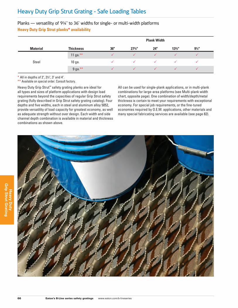
Planks — versatility of 91/4" to 36" widths for single- or multi-width platformsHeavy Duty Grip Strut planks* availability
Plank Width
Material Thickness 36" 273/4" 24" 133/4" 91/4"
11 ga.** P P P P P
Steel 10 ga. P P P P P
9 ga.** P P P P P
* All in depths of 2", 21/2", 3" and 4".** Available on special order. Consult factory.
Heavy Duty Grip Strut™ safety grating planks are ideal for all types and sizes of platform applications with design load requirements beyond the capacities of regular Grip Strut safety grating (fully described in Grip Strut safety grating catalog). Four depths and five widths, each in steel and aluminum alloy 5052, provide versatility of load capacity for greatest economy, as well as adequate strength without over design. Each width and side channel depth combination is available in material and thickness combinations as shown above.
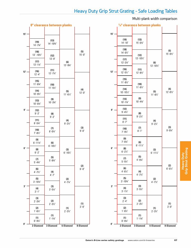
All can be used for single-plank applications, or in multi-plank combinations for large-area platforms (see Multi-plank width chart, opposite page). One combination of width/depth/metal thickness is certain to meet your requirements with exceptional economy. For special job requirements, or the fine-tuned economies required by O.E.M. applications, other materials and many special fabricating services are available (see page 82).
Eaton’s B-Line series safety gratings www.eaton.com/b-lineseries 67
Hea
vy D
uty
G
rip
Str
ut
Gra
tin
g
Heavy Duty Grip Strut Grating - Safe Loading TablesMulti-plank width comparison
2-Diamond 3-Diamond 6-Diamond 8-Diamond 2-Diamond 3-Diamond 6-Diamond 8-Diamond
0" clearance between planks 1⁄8" clearance between planks
6'
3'
12'
15'
9'
0'
6'
3'
12'
15'
9'
0'
(1)3'-0"
(2)6'-0"
(3)9'-0"
(4)12'-0"
(5)15'-0"
(5)11'-61⁄8"
(6)13'-93/4"
(4)9'-21/2"
(3)6'-107⁄8"
(2)4'-71/4"
(1)2'-35⁄8"
(1)1'-13/4"
(1)1'-13/4"
(2)2'-35⁄8"
(3)3'-51/2"
(4)4'-73⁄8"
(5)4'-91/4"
(6)6'-111⁄8"
(7)8'-1"
(8)9'-27⁄8"
(9)10'-43/4"
(10)11'-65⁄8"
(11)12'-81/2"
(12)13'-103⁄8"
(13)15'-01/4"
(19)14'-10"
(18)14'-05⁄8"
(17)13'-31/4"
(16)12'-57⁄8 "
(15)11'-81/2"
(14)10'-101⁄8"
(13)10'-13/4"
(12)9'-43⁄8"
(11)8'-7"
(10)7'-95⁄8"
(9)7'-01/4"
(8)6'-27⁄8"
(7)5'-51/2"
(6)4'-81⁄8"
(5)3'-103/4"
(4)3'-13⁄8"
(3)2'-4"
(2)1'-65⁄8"
(1)0'-91/4"
(1)0'-91/4"
(2)1'-61/2"
(3)2'-33/4"
(4)3'-1"
(5)3'-101/4"
(6)4'-71/2"
(7)5'-43/4"
(8)6'-2"
(9)6'-111/4"
(10)7'-81/2"
(11)8'-53/4"
(12)9'-3"
(13)10'-01/4"
(14)10'-91/2"
(15)11'-63/4"
(16)12'-4"
(17)13'-11/4"
(18)13' -101/2"
(19)14'-73/4"
(2)2'-31/2"
(3)3'-51/4"
(4)4'-7"
(5)5'-83/4"
(6)6'-101/2"
(7)8'-01/4"
(8)9'-2"
(9)10'-33/4"
(10)11'-51/2"
(11)12'-71/4"
(12)13'-9"
(13)14'-103/4"
(1)2'-35⁄8"
(2)4'-73⁄8"
(3)6'-111⁄8"
(4)9'-27⁄8"
(5)11'-65⁄8"
(6)13'-103⁄8"
(1)3'-0"
(2)6'-01⁄8"
(3)9'-01/4"
(4)12'-03⁄8"
(5)15'-01/2"
Eaton’s B-Line series safety gratings www.eaton.com/b-lineseries 68
Heavy D
uty
Grip
Stru
t Gratin
g
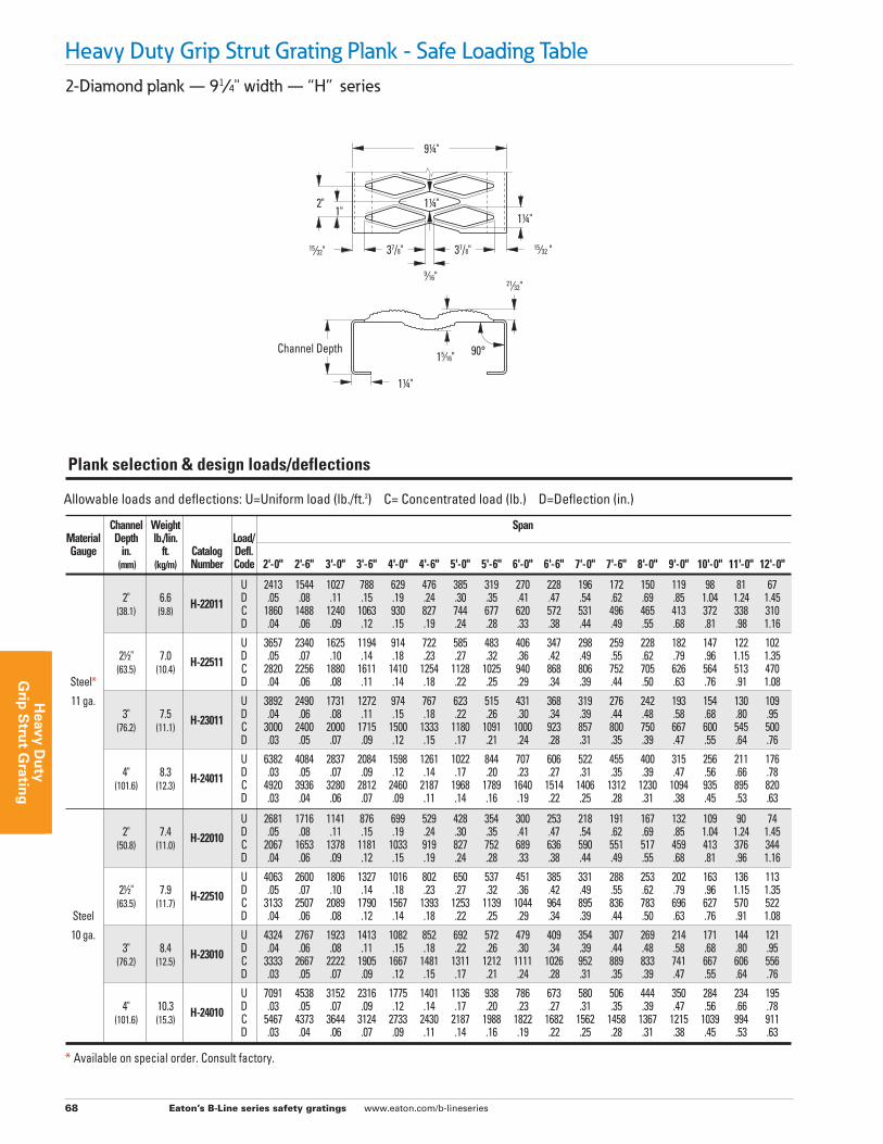
Heavy Duty Grip Strut Grating Plank - Safe Loading Table2-Diamond plank — 91⁄4" width — “H” series
Allowable loads and deflections: U=Uniform load (lb./ft.2) C= Concentrated load (lb.) D=Deflection (in.)
Channel Weight Span Material Depth lb./lin. Load/ Gauge in. ft. Catalog Defl. (mm) (kg/m) Number Code 2'-0" 2'-6" 3'-0" 3'-6" 4'-0" 4'-6" 5'-0" 5'-6" 6'-0" 6'-6" 7'-0" 7'-6" 8'-0" 9'-0" 10'-0" 11'-0" 12'-0"
U 2413 1544 1027 788 629 476 385 319 270 228 196 172 150 119 98 81 67 2" 6.6 H-22011 D .05 .08 .11 .15 .19 .24 .30 .35 .41 .47 .54 .62 .69 .85 1.04 1.24 1.45 (38.1) (9.8) C 1860 1488 1240 1063 930 827 744 677 620 572 531 496 465 413 372 338 310 D .04 .06 .09 .12 .15 .19 .24 .28 .33 .38 .44 .49 .55 .68 .81 .98 1.16
U 3657 2340 1625 1194 914 722 585 483 406 347 298 259 228 182 147 122 102 21/2" 7.0 H-22511 D .05 .07 .10 .14 .18 .23 .27 .32 .36 .42 .49 .55 .62 .79 .96 1.15 1.35 (63.5) (10.4) C 2820 2256 1880 1611 1410 1254 1128 1025 940 868 806 752 705 626 564 513 470 Steel* D .04 .06 .08 .11 .14 .18 .22 .25 .29 .34 .39 .44 .50 .63 .76 .91 1.08
11 ga. U 3892 2490 1731 1272 974 767 623 515 431 368 319 276 242 193 154 130 109 3" 7.5 H-23011 D .04 .06 .08 .11 .15 .18 .22 .26 .30 .34 .39 .44 .48 .58 .68 .80 .95 (76.2) (11.1) C 3000 2400 2000 1715 1500 1333 1180 1091 1000 923 857 800 750 667 600 545 500 D .03 .05 .07 .09 .12 .15 .17 .21 .24 .28 .31 .35 .39 .47 .55 .64 .76
U 6382 4084 2837 2084 1598 1261 1022 844 707 606 522 455 400 315 256 211 176 4" 8.3 H-24011 D .03 .05 .07 .09 .12 .14 .17 .20 .23 .27 .31 .35 .39 .47 .56 .66 .78 (101.6) (12.3) C 4920 3936 3280 2812 2460 2187 1968 1789 1640 1514 1406 1312 1230 1094 935 895 820 D .03 .04 .06 .07 .09 .11 .14 .16 .19 .22 .25 .28 .31 .38 .45 .53 .63
U 2681 1716 1141 876 699 529 428 354 300 253 218 191 167 132 109 90 74 2" 7.4 H-22010 D .05 .08 .11 .15 .19 .24 .30 .35 .41 .47 .54 .62 .69 .85 1.04 1.24 1.45 (50.8) (11.0) C 2067 1653 1378 1181 1033 919 827 752 689 636 590 551 517 459 413 376 344 D .04 .06 .09 .12 .15 .19 .24 .28 .33 .38 .44 .49 .55 .68 .81 .96 1.16
U 4063 2600 1806 1327 1016 802 650 537 451 385 331 288 253 202 163 136 113 21/2" 7.9 H-22510 D .05 .07 .10 .14 .18 .23 .27 .32 .36 .42 .49 .55 .62 .79 .96 1.15 1.35 (63.5) (11.7) C 3133 2507 2089 1790 1567 1393 1253 1139 1044 964 895 836 783 696 627 570 522 Steel D .04 .06 .08 .12 .14 .18 .22 .25 .29 .34 .39 .44 .50 .63 .76 .91 1.08
10 ga. U 4324 2767 1923 1413 1082 852 692 572 479 409 354 307 269 214 171 144 121 3" 8.4 H-23010 D .04 .06 .08 .11 .15 .18 .22 .26 .30 .34 .39 .44 .48 .58 .68 .80 .95 (76.2) (12.5) C 3333 2667 2222 1905 1667 1481 1311 1212 1111 1026 952 889 833 741 667 606 556 D .03 .05 .07 .09 .12 .15 .17 .21 .24 .28 .31 .35 .39 .47 .55 .64 .76
U 7091 4538 3152 2316 1775 1401 1136 938 786 673 580 506 444 350 284 234 195 4" 10.3 H-24010 D .03 .05 .07 .09 .12 .14 .17 .20 .23 .27 .31 .35 .39 .47 .56 .66 .78 (101.6) (15.3) C 5467 4373 3644 3124 2733 2430 2187 1988 1822 1682 1562 1458 1367 1215 1039 994 911 D .03 .04 .06 .07 .09 .11 .14 .16 .19 .22 .25 .28 .31 .38 .45 .53 .63
Plank selection & design loads/deflections
9⁄16"
1" 2"
15⁄32 " 15⁄32"
21⁄32"
11/4"
11/4"
15⁄16"
11/4"
91/4"
37/8" 37/8"
90°Channel Depth
* Available on special order. Consult factory.
Eaton’s B-Line series safety gratings www.eaton.com/b-lineseries 69
Hea
vy D
uty
G
rip
Str
ut
Gra
tin
g
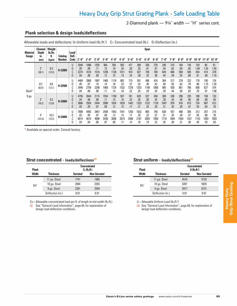
2-Diamond plank — 91/4" width — “H" series cont.
Heavy Duty Grip Strut Grating Plank - Safe Loading Table
Strut concentrated - loads/deflections(2)
Concentrated Plank Cs (lb./ft.) Width Thickness Serrated Non-Serrated
11 ga. Steel 1741 1985 91/4" 10 ga. Steel 2004 2283 9 ga. Steel 2281 2594 Deflection (in.) 0.01 0.01
Cs = Allowable concentrated load per ft. of length at mid-width (lb./ft.) (2) See “General Load information”, page 64, for explanation of design load deflection conditions.
Strut uniform - loads/deflections(2)
Concentrated Plank U (lb./ft.2) Width Thickness Serrated Non-Serrated
11 ga. Steel 4516 5153 91/4" 10 ga. Steel 5201 5925 9 ga. Steel 5917 6731 Deflection (in.) 0.01 0.01
U = Allowable Uniform Load (lb./ft.2) (2) See “General Load information”, page 64, for explanation of design load deflection conditions.
Allowable loads and deflections: U=Uniform load (lb./ft.2) C= Concentrated load (lb.) D=Deflection (in.)
Channel Weight Span Material Depth lb./lin. Load/ Gauge in. ft. Catalog Defl. (mm) (kg/m) Number Code 2'-0" 2'-6" 3'-0" 3'-6" 4'-0" 4'-6" 5'-0" 5'-6" 6'-0" 6'-6" 7'-0" 7'-6" 8'-0" 9'-0" 10'-0" 11'-0" 12'-0"
U 2949 1888 1255 964 769 582 471 389 330 278 240 210 184 145 120 96 81 2" 8.3 H-22009 D .05 .08 .11 .15 .19 .24 .30 .35 .41 .47 .54 .62 .69 .85 1.04 1.24 1.45 (38.1) (12.3) C 2274 1618 1516 1299 1136 1011 910 827 758 700 649 606 569 505 454 414 378 D .04 .06 .09 .12 .15 .19 .24 .28 .33 .38 .44 .49 .55 .68 .81 .98 1.16
U 4469 2860 1987 1460 1118 882 715 591 496 424 364 317 278 222 179 150 124 21/2" 8.8 H-22509 D .05 .07 .10 .14 .18 .23 .27 .32 .36 .42 .49 .55 .62 .79 .96 1.15 1.35 (63.5) (13.1) C 3446 2758 2298 1969 1724 1532 1378 1253 1148 1060 985 920 861 766 690 627 574 Steel* D .04 .06 .08 .11 .14 .18 .22 .25 .29 .34 .39 .44 .50 .63 .76 .91 1.08
9 ga. U 4756 3044 2115 1554 1190 937 761 629 527 450 389 338 296 235 188 158 133 3" 9.3 H-23009 D .04 .06 .08 .11 .15 .18 .22 .26 .30 .34 .39 .44 .48 .58 .68 .80 .95 (76.2) (13.8) C 3666 2934 2444 2096 1834 1629 1442 1333 1222 1129 1047 978 916 815 734 667 612 D .03 .05 .07 .09 .12 .15 .17 .21 .24 .28 .31 .35 .39 .47 .55 .64 .76
U 7800 4992 3467 2548 1953 1541 1250 1032 865 740 638 557 488 385 312 257 215 4" 10.3 H-24009 D .03 .05 .07 .09 .12 .14 .17 .20 .23 .27 .31 .35 .39 .47 .56 .66 .78 (101.6) (15.3) C 6014 4810 4008 3436 3006 2673 2406 2187 2004 1850 1718 1604 1504 1337 1143 1093 1002 D .03 .04 .06 .07 .09 .11 .14 .16 .19 .22 .25 .28 .31 .38 .45 .53 .63
Plank selection & design loads/deflections
* Available on special order. Consult factory.
Eaton’s B-Line series safety gratings www.eaton.com/b-lineseries 70
Heavy D
uty
Grip
Stru
t Gratin
g
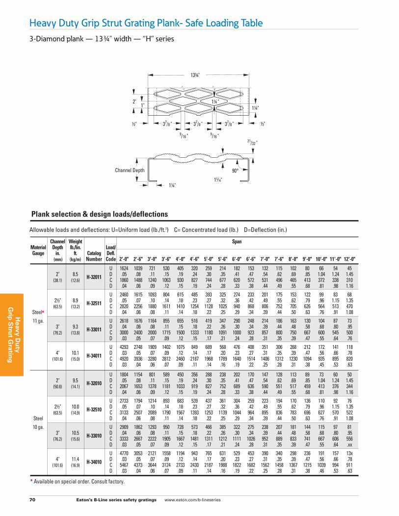
3-Diamond plank — 133/4" width — “H” series
Heavy Duty Grip Strut Grating Plank- Safe Loading Table
Allowable loads and deflections: U=Uniform load (lb./ft.2) C= Concentrated load (lb.) D=Deflection (in.)
Channel Weight Span Material Depth lb./lin. Load/ Gauge in. ft. Catalog Defl. (mm) (kg/m) Number Code 2'-0" 2'-6" 3'-0" 3'-6" 4'-0" 4'-6" 5'-0" 5'-6" 6'-0" 6'-6" 7'-0" 7'-6" 8'-0" 9'-0" 10'-0" 11'-0" 12'-0"
U 1624 1039 721 530 405 320 259 214 182 153 132 115 102 80 66 54 45 2" 8.5 H-32011 D .05 .08 .11 .15 .19 .24 .30 .35 .41 .47 .54 .62 .69 .85 1.04 1.24 1.45 (38.1) (12.6) C 1860 1488 1240 1063 930 827 744 677 620 572 531 496 465 413 372 338 310 D .04 .06 .09 .12 .15 .19 .24 .28 .33 .38 .44 .49 .55 .68 .81 .98 1.16
U 2460 1615 1093 804 615 485 393 325 274 233 201 175 153 122 99 83 68 21/2" 8.9 H-32511 D .05 .07 .10 .14 .18 .23 .27 .32 .36 .42 .49 .55 .62 .79 .96 1.15 1.35 (63.5) (13.2) C 2820 2256 1880 1611 1410 1254 1128 1025 940 868 806 752 705 626 564 513 470 Steel* D .04 .06 .08 .11 .14 .18 .22 .25 .29 .34 .39 .44 .50 .63 .76 .91 1.08
11 ga. U 2618 1676 1164 855 655 516 419 347 290 248 214 186 163 130 104 87 73 3" 9.3 H-33011 D .04 .06 .08 .11 .15 .18 .22 .26 .30 .34 .39 .44 .48 .58 .68 .80 .95 (76.2) (13.8) C 3000 2400 2000 1715 1500 1333 1180 1091 1000 923 857 800 750 667 600 545 500 D .03 .05 .07 .09 .12 .15 .17 .21 .24 .28 .31 .35 .39 .47 .55 .64 .76
U 4293 2748 1909 1402 1075 849 689 568 476 408 351 306 268 212 172 141 118 4" 10.1 H-34011 D .03 .05 .07 .09 .12 .14 .17 .20 .23 .27 .31 .35 .39 .47 .56 .66 .78 (101.6) (15.0) C 4920 3936 3280 2812 2460 2187 1968 1789 1640 1514 1406 1312 1230 1094 935 895 820 D .03 .04 .06 .07 .09 .11 .14 .16 .19 .22 .25 .28 .31 .38 .45 .53 .63
U 1804 1154 801 589 450 356 288 238 202 170 147 128 113 89 73 60 50 2" 9.5 H-32010 D .05 .08 .11 .15 .19 .24 .30 .35 .41 .47 .54 .62 .69 .85 1.04 1.24 1.45 (50.8) (14.1) C 2067 1653 1378 1181 1033 919 827 752 689 636 590 551 517 459 413 376 344 D .04 .06 .09 .12 .15 .19 .24 .28 .33 .38 .44 .49 .55 .68 .81 .98 1.16
U 2733 1794 1214 893 683 539 437 361 304 259 223 194 170 136 110 92 76 21/2" 10.0 H-32510 D .05 .07 .10 .14 .18 .23 .27 .32 .36 .42 .49 .55 .62 .79 .96 1.15 1.35 (63.5) (14.9) C 3133 2507 2089 1790 1567 1393 1253 1139 1044 964 895 836 783 696 627 570 522 Steel D .04 .06 .08 .11 .14 .18 .22 .25 .29 .34 .39 .44 .50 .63 .76 .91 1.08
10 ga. U 2909 1862 1293 950 728 573 466 385 322 275 238 207 181 144 115 97 81 3" 10.5 H-33010 D .04 .06 .08 .11 .15 .18 .22 .26 .30 .34 .39 .44 .48 .58 .68 .80 .95 (76.2) (15.6) C 3333 2667 2222 1905 1667 1481 1311 1212 1111 1026 952 889 833 741 667 606 556 D .03 .05 .07 .09 .12 .15 .17 .21 .24 .28 .31 .35 .39 .47 .55 .64 .xx
U 4770 3053 2121 1558 1194 943 765 631 529 453 390 340 298 236 191 157 13x 4" 11.4 H-34010 D .03 .05 .07 .09 .12 .14 .17 .20 .23 .27 .31 .35 .39 .47 .56 .66 .78 (101.6) (16.9) C 5467 4373 3644 3124 2733 2430 2187 1988 1822 1682 1562 1458 1367 1215 1039 994 911 D .03 .04 .06 .07 .09 .11 .14 .16 .19 .22 .25 .28 .31 .38 .46 .53 .63
Plank selection & design loads/deflections
Channel Depth
9/16 " 9/16 "
1" 2"
1/2" 1/2"
21/32 "
11/4" 15⁄16"
11/4 " 11/4"
133/4"
37/8 " 37/8 " 37/8 "
90°
* Available on special order. Consult factory.
Eaton’s B-Line series safety gratings www.eaton.com/b-lineseries 71
Hea
vy D
uty
G
rip
Str
ut
Gra
tin
g
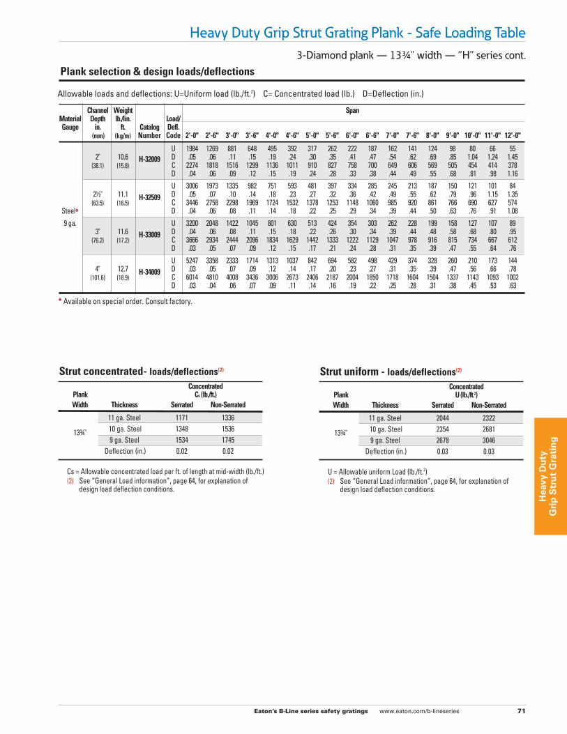
3-Diamond plank — 133/4" width — “H” series cont.
Heavy Duty Grip Strut Grating Plank - Safe Loading Table
Strut concentrated- loads/deflections(2)
Concentrated Plank Cs (lb./ft.) Width Thickness Serrated Non-Serrated
11 ga. Steel 1171 1336 133/4" 10 ga. Steel 1348 1536 9 ga. Steel 1534 1745 Deflection (in.) 0.02 0.02
Cs = Allowable concentrated load per ft. of length at mid-width (lb./ft.) (2) See “General Load information”, page 64, for explanation of design load deflection conditions.
Strut uniform - loads/deflections(2)
Concentrated Plank U (lb./ft.2) Width Thickness Serrated Non-Serrated
11 ga. Steel 2044 2322 133/4" 10 ga. Steel 2354 2681 9 ga. Steel 2678 3046 Deflection (in.) 0.03 0.03
U = Allowable uniform Load (lb./ft.2) (2) See “General Load information”, page 64, for explanation of design load deflection conditions.
Allowable loads and deflections: U=Uniform load (lb./ft.2) C= Concentrated load (lb.) D=Deflection (in.)
Channel Weight Span Material Depth lb./lin. Load/ Gauge in. ft. Catalog Defl. (mm) (kg/m) Number Code 2'-0" 2'-6" 3'-0" 3'-6" 4'-0" 4'-6" 5'-0" 5'-6" 6'-0" 6'-6" 7'-0" 7'-6" 8'-0" 9'-0" 10'-0" 11'-0" 12'-0"
U 1984 1269 881 648 495 392 317 262 222 187 162 141 124 98 80 66 55 2" 10.6 H-32009 D .05 .06 .11 .15 .19 .24 .30 .35 .41 .47 .54 .62 .69 .85 1.04 1.24 1.45 (38.1) (15.8) C 2274 1818 1516 1299 1136 1011 910 827 758 700 649 606 569 505 454 414 378 D .04 .06 .09 .12 .15 .19 .24 .28 .33 .38 .44 .49 .55 .68 .81 .98 1.16
U 3006 1973 1335 982 751 593 481 397 334 285 245 213 187 150 121 101 84 21/2" 11.1 H-32509 D .05 .07 .10 .14 .18 .23 .27 .32 .36 .42 .49 .55 .62 .79 .96 1.15 1.35 (63.5) (16.5) C 3446 2758 2298 1969 1724 1532 1378 1253 1148 1060 985 920 861 766 690 627 574 Steel* D .04 .06 .08 .11 .14 .18 .22 .25 .29 .34 .39 .44 .50 .63 .76 .91 1.08
9 ga. U 3200 2048 1422 1045 801 630 513 424 354 303 262 228 199 158 127 107 89 3" 11.6 H-33009 D .04 .06 .08 .11 .15 .18 .22 .26 .30 .34 .39 .44 .48 .58 .68 .80 .95 (76.2) (17.2) C 3666 2934 2444 2096 1834 1629 1442 1333 1222 1129 1047 978 916 815 734 667 612 D .03 .05 .07 .09 .12 .15 .17 .21 .24 .28 .31 .35 .39 .47 .55 .64 .76
U 5247 3358 2333 1714 1313 1037 842 694 582 498 429 374 328 260 210 173 144 4" 12.7 H-34009 D .03 .05 .07 .09 .12 .14 .17 .20 .23 .27 .31 .35 .39 .47 .56 .66 .78 (101.6) (18.9) C 6014 4810 4008 3436 3006 2673 2406 2187 2004 1850 1718 1604 1504 1337 1143 1093 1002 D .03 .04 .06 .07 .09 .11 .14 .16 .19 .22 .25 .28 .31 .38 .45 .53 .63
Plank selection & design loads/deflections
* Available on special order. Consult factory.
Eaton’s B-Line series safety gratings www.eaton.com/b-lineseries 72
Heavy D
uty
Grip
Stru
t Gratin
g
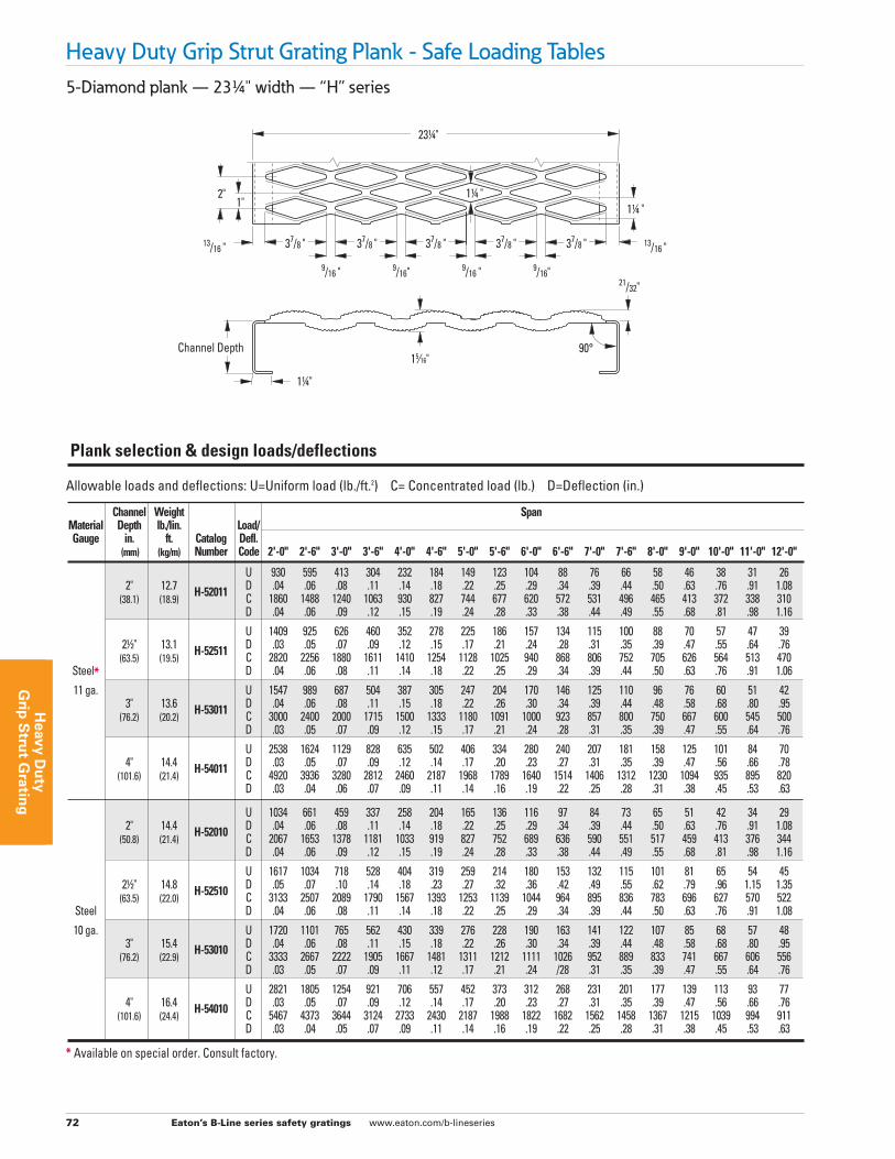
Heavy Duty Grip Strut Grating Plank - Safe Loading Tables5-Diamond plank — 231/4" width — “H” series
Allowable loads and deflections: U=Uniform load (lb./ft.2) C= Concentrated load (lb.) D=Deflection (in.)
Channel Weight Span Material Depth lb./lin. Load/ Gauge in. ft. Catalog Defl. (mm) (kg/m) Number Code 2'-0" 2'-6" 3'-0" 3'-6" 4'-0" 4'-6" 5'-0" 5'-6" 6'-0" 6'-6" 7'-0" 7'-6" 8'-0" 9'-0" 10'-0" 11'-0" 12'-0"
U 930 595 413 304 232 184 149 123 104 88 76 66 58 46 38 31 26 2" 12.7 H-52011 D .04 .06 .08 .11 .14 .18 .22 .25 .29 .34 .39 .44 .50 .63 .76 .91 1.08 (38.1) (18.9) C 1860 1488 1240 1063 930 827 744 677 620 572 531 496 465 413 372 338 310 D .04 .06 .09 .12 .15 .19 .24 .28 .33 .38 .44 .49 .55 .68 .81 .98 1.16
U 1409 925 626 460 352 278 225 186 157 134 115 100 88 70 57 47 39 21/2" 13.1 H-52511 D .03 .05 .07 .09 .12 .15 .17 .21 .24 .28 .31 .35 .39 .47 .55 .64 .76 (63.5) (19.5) C 2820 2256 1880 1611 1410 1254 1128 1025 940 868 806 752 705 626 564 513 470 Steel* D .04 .06 .08 .11 .14 .18 .22 .25 .29 .34 .39 .44 .50 .63 .76 .91 1.06
11 ga. U 1547 989 687 504 387 305 247 204 170 146 125 110 96 76 60 51 42 3" 13.6 H-53011 D .04 .06 .08 .11 .15 .18 .22 .26 .30 .34 .39 .44 .48 .58 .68 .80 .95 (76.2) (20.2) C 3000 2400 2000 1715 1500 1333 1180 1091 1000 923 857 800 750 667 600 545 500 D .03 .05 .07 .09 .12 .15 .17 .21 .24 .28 .31 .35 .39 .47 .55 .64 .76
U 2538 1624 1129 828 635 502 406 334 280 240 207 181 158 125 101 84 70 4" 14.4 H-54011 D .03 .05 .07 .09 .12 .14 .17 .20 .23 .27 .31 .35 .39 .47 .56 .66 .78 (101.6) (21.4) C 4920 3936 3280 2812 2460 2187 1968 1789 1640 1514 1406 1312 1230 1094 935 895 820 D .03 .04 .06 .07 .09 .11 .14 .16 .19 .22 .25 .28 .31 .38 .45 .53 .63
U 1034 661 459 337 258 204 165 136 116 97 84 73 65 51 42 34 29 2" 14.4 H-52010 D .04 .06 .08 .11 .14 .18 .22 .25 .29 .34 .39 .44 .50 .63 .76 .91 1.08 (50.8) (21.4) C 2067 1653 1378 1181 1033 919 827 752 689 636 590 551 517 459 413 376 344 D .04 .06 .09 .12 .15 .19 .24 .28 .33 .38 .44 .49 .55 .68 .81 .98 1.16
U 1617 1034 718 528 404 319 259 214 180 153 132 115 101 81 65 54 45 21/2" 14.8 H-52510 D .05 .07 .10 .14 .18 .23 .27 .32 .36 .42 .49 .55 .62 .79 .96 1.15 1.35 (63.5) (22.0) C 3133 2507 2089 1790 1567 1393 1253 1139 1044 964 895 836 783 696 627 570 522 Steel D .04 .06 .08 .11 .14 .18 .22 .25 .29 .34 .39 .44 .50 .63 .76 .91 1.08
10 ga. U 1720 1101 765 562 430 339 276 228 190 163 141 122 107 85 68 57 48 3" 15.4 H-53010 D .04 .06 .08 .11 .15 .18 .22 .26 .30 .34 .39 .44 .48 .58 .68 .80 .95 (76.2) (22.9) C 3333 2667 2222 1905 1667 1481 1311 1212 1111 1026 952 889 833 741 667 606 556 D .03 .05 .07 .09 .11 .12 .17 .21 .24 /28 .31 .35 .39 .47 .55 .64 .76
U 2821 1805 1254 921 706 557 452 373 312 268 231 201 177 139 113 93 77 4" 16.4 H-54010 D .03 .05 .07 .09 .12 .14 .17 .20 .23 .27 .31 .35 .39 .47 .56 .66 .76 (101.6) (24.4) C 5467 4373 3644 3124 2733 2430 2187 1988 1822 1682 1562 1458 1367 1215 1039 994 911 D .03 .04 .05 .07 .09 .11 .14 .16 .19 .22 .25 .28 .31 .38 .45 .53 .63
Plank selection & design loads/deflections
9/16 " 9/16" 9/16 " 9/16"
1" 2"
13/16 " 13/16 "
21/32"
11/4"
15⁄16"
11/4 " 11/4 "
37/8 " 37/8 " 37/8 " 37/8 " 37/8 "
231/4"
90°Channel Depth
* Available on special order. Consult factory.
Eaton’s B-Line series safety gratings www.eaton.com/b-lineseries 73
Hea
vy D
uty
G
rip
Str
ut
Gra
tin
g
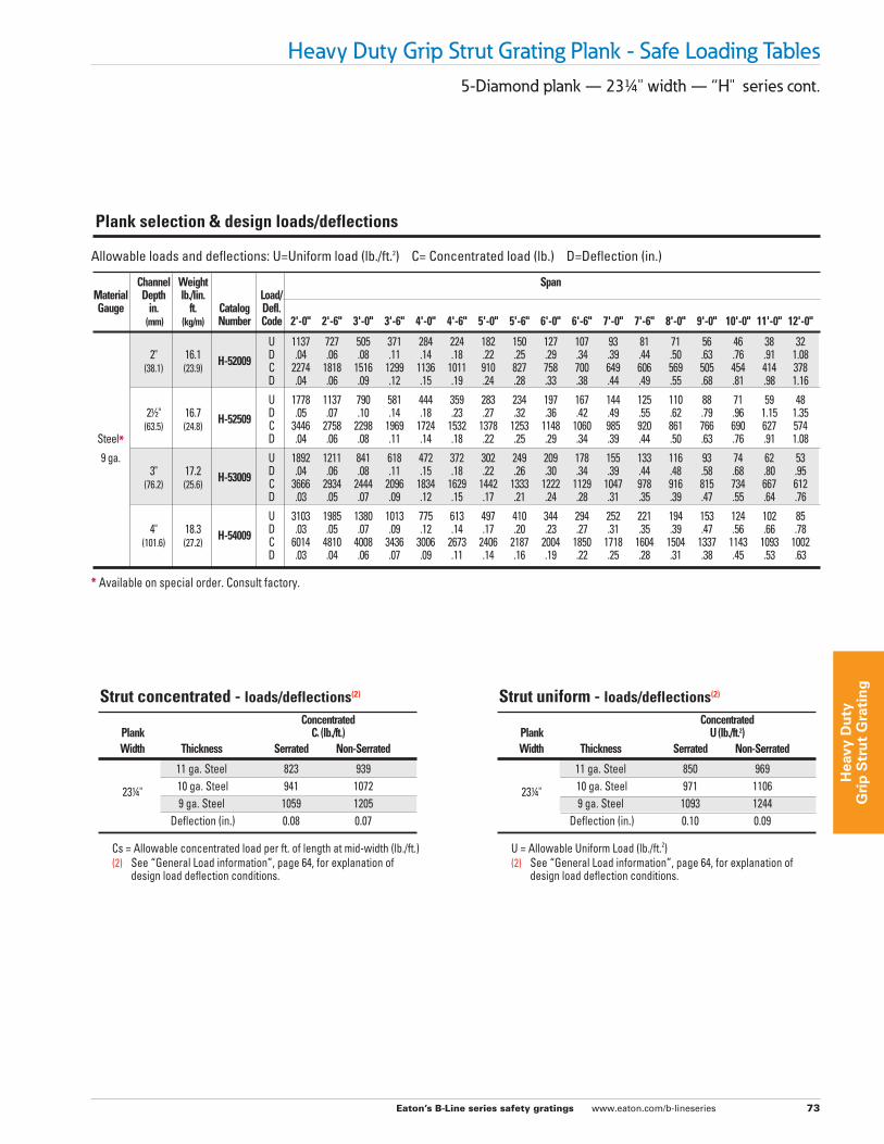
Heavy Duty Grip Strut Grating Plank - Safe Loading Tables5-Diamond plank — 231/4" width — “H" series cont.
Strut concentrated - loads/deflections(2)
Concentrated Plank Cs (lb./ft.) Width Thickness Serrated Non-Serrated
11 ga. Steel 823 939 231/4" 10 ga. Steel 941 1072 9 ga. Steel 1059 1205 Deflection (in.) 0.08 0.07
Cs = Allowable concentrated load per ft. of length at mid-width (lb./ft.) (2) See “General Load information”, page 64, for explanation of design load deflection conditions.
Strut uniform - loads/deflections(2)
Concentrated Plank U (lb./ft.2) Width Thickness Serrated Non-Serrated
11 ga. Steel 850 969 231/4" 10 ga. Steel 971 1106 9 ga. Steel 1093 1244 Deflection (in.) 0.10 0.09
U = Allowable Uniform Load (lb./ft.2) (2) See “General Load information”, page 64, for explanation of design load deflection conditions.
Allowable loads and deflections: U=Uniform load (lb./ft.2) C= Concentrated load (lb.) D=Deflection (in.)
Channel Weight Span Material Depth lb./lin. Load/ Gauge in. ft. Catalog Defl. (mm) (kg/m) Number Code 2'-0" 2'-6" 3'-0" 3'-6" 4'-0" 4'-6" 5'-0" 5'-6" 6'-0" 6'-6" 7'-0" 7'-6" 8'-0" 9'-0" 10'-0" 11'-0" 12'-0"
U 1137 727 505 371 284 224 182 150 127 107 93 81 71 56 46 38 32 2" 16.1 H-52009 D .04 .06 .08 .11 .14 .18 .22 .25 .29 .34 .39 .44 .50 .63 .76 .91 1.08 (38.1) (23.9) C 2274 1818 1516 1299 1136 1011 910 827 758 700 649 606 569 505 454 414 378 D .04 .06 .09 .12 .15 .19 .24 .28 .33 .38 .44 .49 .55 .68 .81 .98 1.16
U 1778 1137 790 581 444 359 283 234 197 167 144 125 110 88 71 59 48 21/2" 16.7 H-52509 D .05 .07 .10 .14 .18 .23 .27 .32 .36 .42 .49 .55 .62 .79 .96 1.15 1.35 (63.5) (24.8) C 3446 2758 2298 1969 1724 1532 1378 1253 1148 1060 985 920 861 766 690 627 574 Steel* D .04 .06 .08 .11 .14 .18 .22 .25 .29 .34 .39 .44 .50 .63 .76 .91 1.08
9 ga. U 1892 1211 841 618 472 372 302 249 209 178 155 133 116 93 74 62 53 3" 17.2 H-53009 D .04 .06 .08 .11 .15 .18 .22 .26 .30 .34 .39 .44 .48 .58 .68 .80 .95 (76.2) (25.6) C 3666 2934 2444 2096 1834 1629 1442 1333 1222 1129 1047 978 916 815 734 667 612 D .03 .05 .07 .09 .12 .15 .17 .21 .24 .28 .31 .35 .39 .47 .55 .64 .76
U 3103 1985 1380 1013 775 613 497 410 344 294 252 221 194 153 124 102 85 4" 18.3 H-54009 D .03 .05 .07 .09 .12 .14 .17 .20 .23 .27 .31 .35 .39 .47 .56 .66 .78 (101.6) (27.2) C 6014 4810 4008 3436 3006 2673 2406 2187 2004 1850 1718 1604 1504 1337 1143 1093 1002 D .03 .04 .06 .07 .09 .11 .14 .16 .19 .22 .25 .28 .31 .38 .45 .53 .63
Plank selection & design loads/deflections
* Available on special order. Consult factory.
Eaton’s B-Line series safety gratings www.eaton.com/b-lineseries 74
Heavy D
uty
Grip
Stru
t Gratin
g
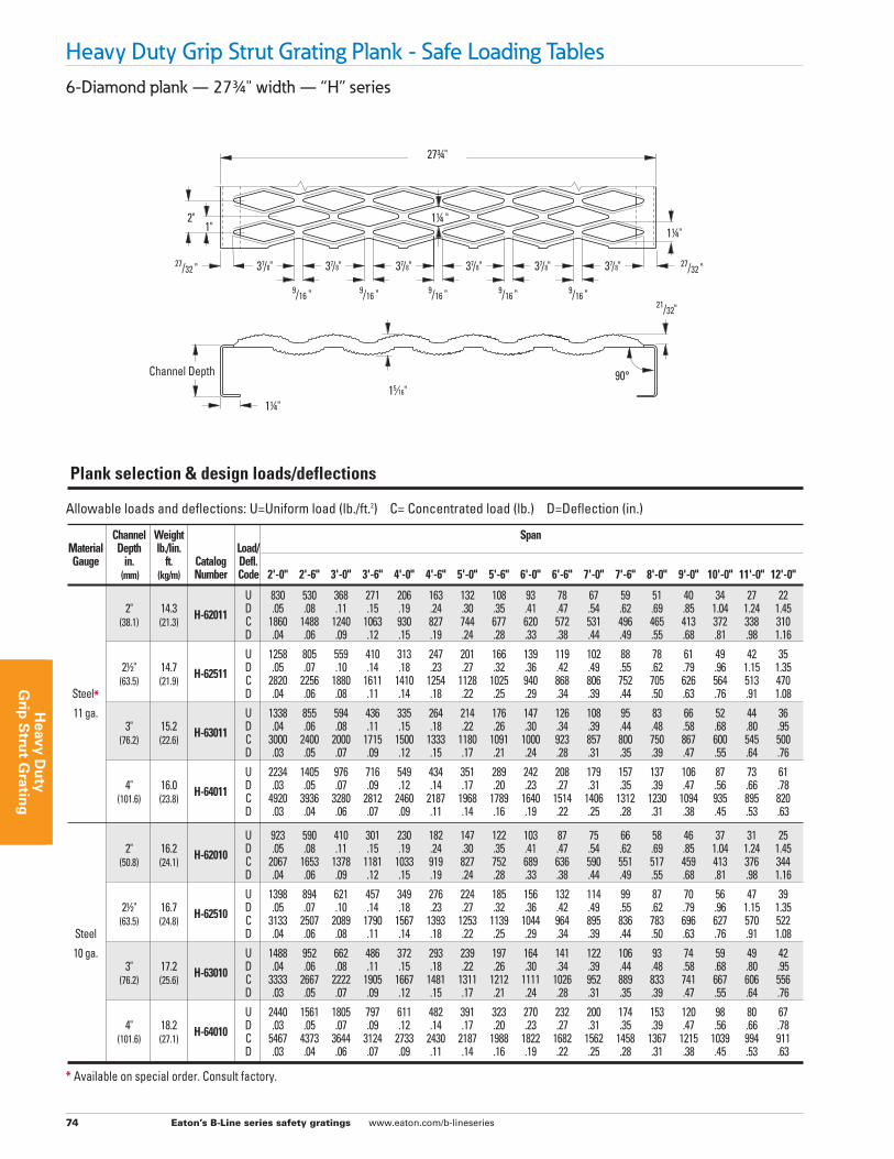
6-Diamond plank — 273/4" width — “H” series
Heavy Duty Grip Strut Grating Plank - Safe Loading Tables
Allowable loads and deflections: U=Uniform load (lb./ft.2) C= Concentrated load (lb.) D=Deflection (in.)
Channel Weight Span Material Depth lb./lin. Load/ Gauge in. ft. Catalog Defl. (mm) (kg/m) Number Code 2'-0" 2'-6" 3'-0" 3'-6" 4'-0" 4'-6" 5'-0" 5'-6" 6'-0" 6'-6" 7'-0" 7'-6" 8'-0" 9'-0" 10'-0" 11'-0" 12'-0"
U 830 530 368 271 206 163 132 108 93 78 67 59 51 40 34 27 22 2" 14.3 H-62011 D .05 .08 .11 .15 .19 .24 .30 .35 .41 .47 .54 .62 .69 .85 1.04 1.24 1.45 (38.1) (21.3) C 1860 1488 1240 1063 930 827 744 677 620 572 531 496 465 413 372 338 310 D .04 .06 .09 .12 .15 .19 .24 .28 .33 .38 .44 .49 .55 .68 .81 .98 1.16
U 1258 805 559 410 313 247 201 166 139 119 102 88 78 61 49 42 35 21/2" 14.7 H-62511 D .05 .07 .10 .14 .18 .23 .27 .32 .36 .42 .49 .55 .62 .79 .96 1.15 1.35 (63.5) (21.9) C 2820 2256 1880 1611 1410 1254 1128 1025 940 868 806 752 705 626 564 513 470 Steel* D .04 .06 .08 .11 .14 .18 .22 .25 .29 .34 .39 .44 .50 .63 .76 .91 1.08
11 ga. U 1338 855 594 436 335 264 214 176 147 126 108 95 83 66 52 44 36 3" 15.2 H-63011 D .04 .06 .08 .11 .15 .18 .22 .26 .30 .34 .39 .44 .48 .58 .68 .80 .95 (76.2) (22.6) C 3000 2400 2000 1715 1500 1333 1180 1091 1000 923 857 800 750 867 600 545 500 D .03 .05 .07 .09 .12 .15 .17 .21 .24 .28 .31 .35 .39 .47 .55 .64 .76
U 2234 1405 976 716 549 434 351 289 242 208 179 157 137 106 87 73 61 4" 16.0 H-64011 D .03 .05 .07 .09 .12 .14 .17 .20 .23 .27 .31 .35 .39 .47 .56 .66 .78 (101.6) (23.8) C 4920 3936 3280 2812 2460 2187 1968 1789 1640 1514 1406 1312 1230 1094 935 895 820 D .03 .04 .06 .07 .09 .11 .14 .16 .19 .22 .25 .28 .31 .38 .45 .53 .63
U 923 590 410 301 230 182 147 122 103 87 75 66 58 46 37 31 25 2" 16.2 H-62010 D .05 .08 .11 .15 .19 .24 .30 .35 .41 .47 .54 .62 .69 .85 1.04 1.24 1.45 (50.8) (24.1) C 2067 1653 1378 1181 1033 919 827 752 689 636 590 551 517 459 413 376 344 D .04 .06 .09 .12 .15 .19 .24 .28 .33 .38 .44 .49 .55 .68 .81 .98 1.16
U 1398 894 621 457 349 276 224 185 156 132 114 99 87 70 56 47 39 21/2" 16.7 H-62510 D .05 .07 .10 .14 .18 .23 .27 .32 .36 .42 .49 .55 .62 .79 .96 1.15 1.35 (63.5) (24.8) C 3133 2507 2089 1790 1567 1393 1253 1139 1044 964 895 836 783 696 627 570 522 Steel D .04 .06 .08 .11 .14 .18 .22 .25 .29 .34 .39 .44 .50 .63 .76 .91 1.08
10 ga. U 1488 952 662 486 372 293 239 197 164 141 122 106 93 74 59 49 42 3" 17.2 H-63010 D .04 .06 .08 .11 .15 .18 .22 .26 .30 .34 .39 .44 .48 .58 .68 .80 .95 (76.2) (25.6) C 3333 2667 2222 1905 1667 1481 1311 1212 1111 1026 952 889 833 741 667 606 556 D .03 .05 .07 .09 .12 .15 .17 .21 .24 .28 .31 .35 .39 .47 .55 .64 .76
U 2440 1561 1805 797 611 482 391 323 270 232 200 174 153 120 98 80 67 4" 18.2 H-64010 D .03 .05 .07 .09 .12 .14 .17 .20 .23 .27 .31 .35 .39 .47 .56 .66 .78 (101.6) (27.1) C 5467 4373 3644 3124 2733 2430 2187 1988 1822 1682 1562 1458 1367 1215 1039 994 911 D .03 .04 .06 .07 .09 .11 .14 .16 .19 .22 .25 .28 .31 .38 .45 .53 .63
Plank selection & design loads/deflections
Channel Depth
9/16 " 9/16 " 9/16 " 9/16 " 9/16 "
1" 2"
27/32 " 27/32 "
21/32"
11/4" 15⁄16"
11/4 " 11/4"
273/4"
37/8" 37/8" 37/8" 37/8" 37/8" 37/8"
90°
* Available on special order. Consult factory.

Eaton’s B-Line series safety gratings www.eaton.com/b-lineseries 75
Hea
vy D
uty
G
rip
Str
ut
Gra
tin
g
6-Diamond plank — 273/4" width — “H” series cont.
Heavy Duty Grip Strut Grating Plank - Safe Loading Tables
Strut concentrated - loads/deflections(2)
Concentrated Plank Cs (lb./ft.) Width Thickness Serrated Non-Serrated
11 ga. Steel 690 793 231/4" 10 ga. Steel 788 906 9 ga. Steel 887 1019 Deflection (in.) 0.11 0.10
Cs = Allowable concentrated load per ft. of length at mid-width (lb./ft.) (2) See “General Load information”, page 64, for explanation of design load deflection conditions.
Strut uniform - loads/deflections(2)
Concentrated Plank U (lb./ft.2) Width Thickness Serrated Non-Serrated
11 ga. Steel 597 686 231/4" 10 ga. Steel 682 784 9 ga. Steel 767 882 Deflection (in.) 0.14 0.13
U = Allowable Uniform Load (lb./ft.2) (2) See “General Load information”, page 64, for explanation of design load deflection conditions.
Allowable loads and deflections: U=Uniform load (lb./ft.2) C= Concentrated load (lb.) D=Deflection (in.)
Channel Weight Span Material Depth lb./lin. Load/ Gauge in. ft. Catalog Defl. (mm) (kg/m) Number Code 2'-0" 2'-6" 3'-0" 3'-6" 4'-0" 4'-6" 5'-0" 5'-6" 6'-0" 6'-6" 7'-0" 7'-6" 8'-0" 9'-0" 10'-0" 11'-0" 12'-0"
U 1013 650 450 330 253 200 162 134 112 95 81 71 63 49 40 34 27 2" 18.2 H-62009 D .05 .08 .11 .15 .19 .24 .30 .35 .41 .47 .54 .62 .69 .85 1.04 1.24 1.45 (38.1) (27.1) C 2274 1818 1516 1299 1136 1011 910 827 758 700 649 606 569 505 454 414 378 D .04 .06 .09 .12 .15 .19 .24 .28 .33 .38 .44 .49 .55 .68 .81 .98 1.16
U 1537 983 683 502 384 303 245 202 170 144 125 108 95 76 61 51 42 21/2" 18.7 H-62509 D .05 .07 .10 .14 .18 .23 .27 .32 .36 .42 .49 .55 .62 .79 .96 1.15 1.35 (63.5) (27.8) C 3446 2758 2298 1969 1724 1532 1378 1253 1148 1060 985 920 861 766 690 627 574 Steel* D .04 .06 .08 .11 .14 .18 .22 .25 .29 .34 .39 .44 .50 .63 .76 .91 1.08
9 ga. U 1636 1047 727 534 408 322 261 215 181 154 134 115 100 80 64 54 46 3" 19.3 H-63009 D .04 .06 .08 .11 .15 .18 .22 .26 .30 .34 .39 .44 .48 .58 .68 .80 .95 (76.2) (28.7) C 3666 2934 2444 2096 1834 1629 1442 1333 1222 1129 1047 978 916 815 734 667 612 D .03 .05 .07 .09 .12 .15 .17 .21 .24 .28 .31 .35 .39 .47 .55 .64 .76
U 2684 1717 1194 876 671 530 430 355 298 254 218 191 168 132 107 88 74 4" 19.8 H-64009 D .03 .05 .07 .09 .12 .14 .17 .20 .23 .27 .31 .35 .39 .47 .56 .66 .78 (101.6) (29.4) C 6014 4810 4008 3436 3006 2673 2406 2187 2004 1850 1718 1604 1505 1337 1143 1093 1002 D .03 .04 .06 .07 .09 .11 .14 .16 .19 .22 .25 .28 .31 .38 .45 .53 .63
Plank selection & design loads/deflections
* Available on special order. Consult factory.
Eaton’s B-Line series safety gratings www.eaton.com/b-lineseries 76
Heavy D
uty
Grip
Stru
t Gratin
g
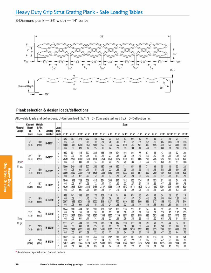
8-Diamond plank — 36" width — “H” series
Heavy Duty Grip Strut Grating Plank - Safe Loading Tables
Allowable loads and deflections: U=Uniform load (lb./ft.2) C= Concentrated load (lb.) D=Deflection (in.)
Channel Weight Span Material Depth lb./lin. Load/ Gauge in. ft. Catalog Defl. (mm) (kg/m) Number Code 2'-0" 2'-6" 3'-0" 3'-6" 4'-0" 4'-6" 5'-0" 5'-6" 6'-0" 6'-6" 7'-0" 7'-6" 8'-0" 9'-0" 10'-0" 11'-0" 12'-0"
U 620 397 275 203 155 122 99 82 69 59 50 44 39 31 25 21 17 2" 18.0 H-82011 D .05 .08 .11 .15 .19 .24 .30 .35 .41 .47 .54 .62 .69 .85 1.04 1.24 1.45 (38.1) (26.8) C 1860 1488 1240 1063 930 827 744 677 620 572 531 496 465 413 372 338 310 D .04 .06 .09 .12 .15 .19 .24 .28 .33 .38 .44 .49 .55 .68 .81 .98 1.16
U 950 601 418 307 235 185 150 124 104 89 77 67 59 47 38 32 26 21/2" 18.4 H-82511 D .05 .07 .10 .14 .18 .23 .27 .32 .36 .42 .49 .55 .62 .79 .96 1.15 1.35 (63.5) (27.4) C 2820 2256 1880 1611 1410 1254 1128 1025 940 868 806 752 705 626 564 513 470 Steel* D .04 .06 .08 .11 .14 .18 .22 .25 .29 .34 .39 .44 .50 .63 .76 .91 1.08
11 ga. U 1000 640 445 327 250 197 160 132 111 95 82 71 62 50 40 33 28 3" 18.9 H-83011 D .04 .06 .08 .11 .15 .18 .22 .26 .30 .34 .39 .44 .48 .58 .68 .80 .95 (76.2) (28.1) C 3000 2400 2000 1715 1500 1333 1180 1091 1000 923 857 800 750 667 600 545 500 D .03 .05 .07 .09 .12 .15 .17 .21 .24 .28 .31 .35 .39 .47 .55 .64 .76
U 1640 1049 729 536 410 324 263 217 182 156 134 117 103 81 66 54 45 4" 19.7 H-84011 D .03 .05 .07 .09 .12 .14 .17 .20 .23 .27 .31 .35 .39 .47 .56 .66 .78 (101.6) (29.3) C 4920 3936 3280 2812 2460 2187 1968 1789 1640 1514 1406 1312 1230 1094 935 895 820 D .03 .04 .06 .07 .09 .11 .14 .16 .19 .22 .25 .28 .31 .38 .45 .53 .63
U 689 441 306 225 172 136 110 91 77 65 56 49 43 34 28 23 19 2" 19.9 H-82010 D .05 .08 .11 .15 .19 .24 .30 .35 .41 .47 .54 .62 .69 .85 1.04 1.24 1.45 (50.8) (29.6) C 2067 1653 1378 1181 1033 919 827 752 689 636 590 551 517 459 413 376 344 D .04 .06 .09 .12 .15 .19 .24 .28 .33 .38 .44 .49 .55 .68 .81 .98 1.16
U 1044 668 464 341 261 206 167 138 116 99 85 74 65 52 42 35 29 21/2" 20.4 H-82510 D .05 .07 .10 .14 .18 .23 .27 .32 .36 .42 .49 .55 .62 .79 .96 1.15 1.35 (63.5) (30.3) C 3133 2507 2089 1790 1567 1393 1253 1139 1944 964 895 836 783 696 627 570 522 Steel D .04 .06 .08 .11 .14 .18 .22 .25 .29 .34 .39 .44 .50 .63 .76 .91 1.08
10 ga. U 1111 711 494 363 278 219 178 147 123 105 91 79 69 55 44 37 31 3" 20.9 H-83010 D .04 .06 .08 .11 .15 .18 .22 .26 .30 .34 .39 .44 .48 .58 .68 .80 .95 (76.2) (31.1) C 3333 2667 2222 1905 1667 1481 1311 1212 1111 1026 952 889 833 741 667 606 556 D .03 .05 .07 .09 .12 .15 .17 .21 .24 .28 .31 .35 .39 .47 .55 .64 .76
U 1822 1166 810 595 456 360 292 241 202 173 149 130 114 90 73 60 50 4" 21.8 H-84010 D .03 .05 .07 .09 .12 .14 .17 .20 .23 .27 .31 .35 .39 .47 .56 .66 .78 (101.6) (32.4) C 5467 4373 3644 3124 2733 2430 2187 1988 1822 1682 1562 1458 1367 1215 1039 994 911 D .03 .04 .06 .07 .09 .11 .14 .16 .19 .22 .25 .28 .31 .38 .45 .53 .63
Plank selection & design loads/deflections
36"
Channel Depth
9/16 " 9/16 " 9/16 " 9/16 " 9/16 "
1" 2"
17/32 " 17/32 "
21/32"
11/4 "
15⁄16"
11/4 "
37/8 " 37/8 " 37/8 " 37/8 " 37/8 " 37/8 "
9/16 " 9/16 "
37/8 " 37/8 "
90°
* Available on special order. Consult factory.

Eaton’s B-Line series safety gratings www.eaton.com/b-lineseries 77
Hea
vy D
uty
G
rip
Str
ut
Gra
tin
g
8-Diamond plank — 36" width — “H" series cont.
Heavy Duty Grip Strut Grating Plank - Safe Loading Tables
Strut concentrated - loads/deflections(2)
Concentrated Plank Cs (lb./ft.) Width Thickness Serrated Non-Serrated
11 ga. Steel 447 510 36" 10 ga. Steel 515 587 9 ga. Steel 586 667 Deflection (in.) 0.16 0.15
Cs = Allowable concentrated load per ft. of length at mid-width (lb./ft.) (2) See “General Load information”, page 64, for explanation of design load deflection conditions.
Strut uniform - loads/deflections(2)
Concentrated Plank U (lb./ft.2) Width Thickness Serrated Non-Serrated
11 ga. Steel 298 340 36" 10 ga. Steel 343 391 9 ga. Steel 391 444 Deflection (in.) 0.20 0.19
U = Allowable Uniform Load (lb./ft.2) (2) See “General Load information”, page 64, for explanation of design load deflection conditions.
Allowable loads and deflections: U=Uniform load (lb./ft.2) C= Concentrated load (lb.) D=Deflection (in.)
Channel Weight Span Material Depth lb./lin. Load/ Gauge in. ft. Catalog Defl. (mm) (kg/m) Number Code 2'-0" 2'-6" 3'-0" 3'-6" 4'-0" 4'-6" 5'-0" 5'-6" 6'-0" 6'-6" 7'-0" 7'-6" 8'-0" 9'-0" 10'-0" 11'-0" 12'-0"
U 758 485 337 248 189 150 121 100 85 72 62 54 47 37 31 25 21 2" 22.1 H-82009 D .05 .08 .11 .15 .19 .24 .30 .35 .41 .47 .54 .62 .69 .85 1.04 1.24 1.45 (38.1) (32.9) C 2274 1818 1516 1299 1136 1011 910 827 758 700 649 606 569 505 454 414 378 D .04 .06 .09 .12 .15 .19 .24 .28 .33 .38 .44 .49 .55 .68 .81 .98 1.16
U 1148 735 510 375 287 227 184 152 128 109 94 81 72 57 46 39 32 21/2" 22.7 H-82509 D .05 .07 .10 .14 .18 .23 .27 .32 .36 .42 .49 .55 .62 .79 .96 1.15 1.35 (63.5) (33.8) C 3446 2758 2298 1969 1724 1532 1378 1253 1148 1060 985 920 861 766 690 627 574 Steel* D .04 .06 .08 .11 .14 .18 .22 .25 .29 .34 .39 .44 .50 .63 .76 .91 1.08
9 ga. U 1222 782 543 399 306 241 196 162 135 116 100 87 76 61 48 41 34 3" 23.9 H-83009 D .04 .06 .08 .11 .15 .18 .22 .26 .30 .34 .39 .44 .48 .58 .68 .80 .95 (76.2) (35.5) C 3666 2934 2444 2096 1834 1629 1442 1333 1222 1129 1047 978 916 815 734 667 612 D .03 .05 .07 .09 .12 .15 .17 .21 .24 .28 .31 .35 .39 .47 .55 .64 .76
U 2004 1283 891 655 502 396 321 265 222 190 164 143 125 99 80 66 56 4" 24.2 H-84009 D .03 .05 .07 .09 .12 .14 .17 .20 .23 .27 .31 .35 .39 .47 .56 .66 .78 (101.6) (36.0) C 6014 4810 4008 3436 3006 2673 2406 2187 2004 1850 1718 1604 1504 1337 1143 1093 1002 D .03 .04 .06 .07 .09 .11 .14 .16 .19 .22 .25 .28 .31 .38 .45 .53 .63
Plank selection & design loads/deflections
* Available on special order. Consult factory.
Eaton’s B-Line series safety gratings www.eaton.com/b-lineseries 78
Heavy D
uty
Grip
Stru
t Gratin
g
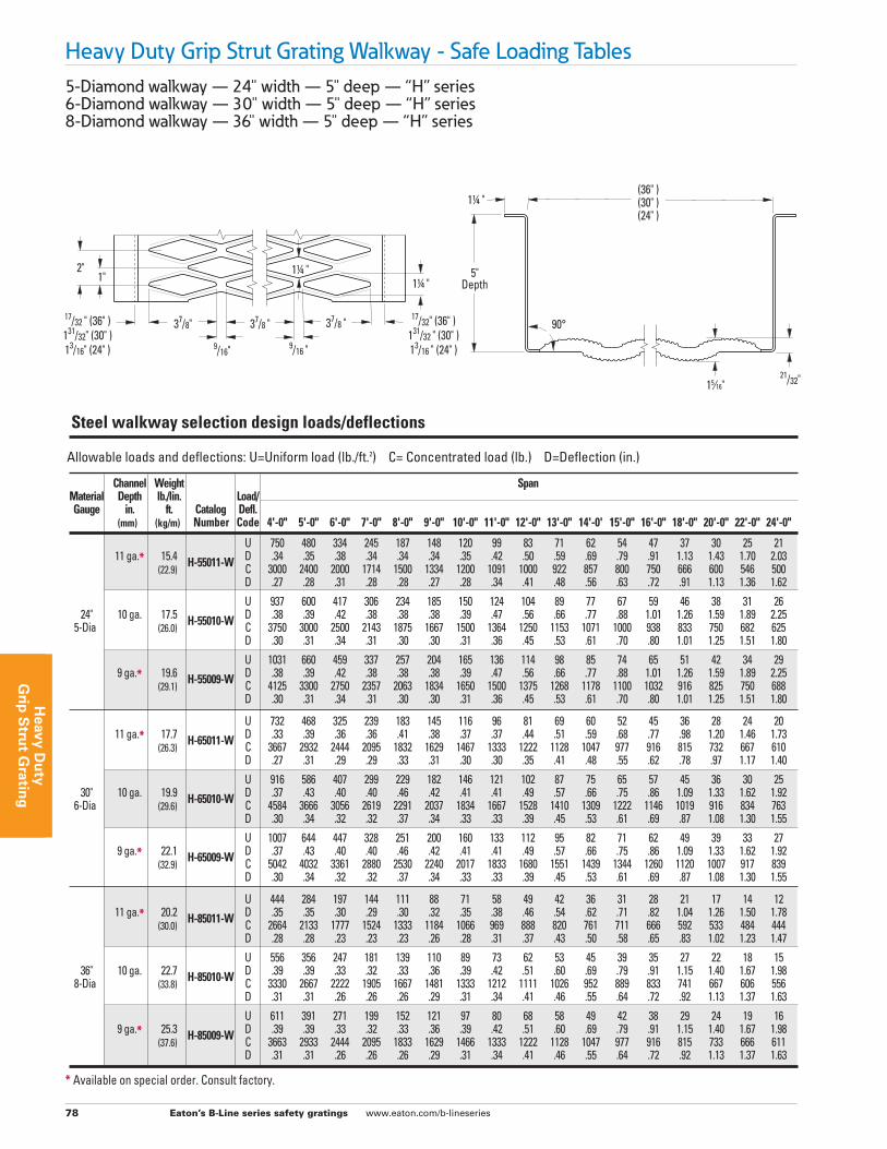
Heavy Duty Grip Strut Grating Walkway - Safe Loading Tables5-Diamond walkway — 24" width — 5" deep — “H” series 6-Diamond walkway — 30" width — 5" deep — “H” series 8-Diamond walkway — 36" width — 5" deep — “H” series
Allowable loads and deflections: U=Uniform load (lb./ft.2) C= Concentrated load (lb.) D=Deflection (in.)
Channel Weight Span Material Depth lb./lin. Load/ Gauge in. ft. Catalog Defl. (mm) (kg/m) Number Code 4'-0" 5'-0" 6'-0" 7'-0" 8'-0" 9'-0" 10'-0" 11'-0" 12'-0" 13'-0" 14'-0' 15'-0" 16'-0" 18'-0" 20'-0" 22'-0" 24'-0"
U 750 480 334 245 187 148 120 99 83 71 62 54 47 37 30 25 21 11 ga.* 15.4 H-55011-W D .34 .35 .38 .34 .34 .34 .35 .42 .50 .59 .69 .79 .91 1.13 1.43 1.70 2.03 (22.9) C 3000 2400 2000 1714 1500 1334 1200 1091 1000 922 857 800 750 666 600 546 500 D .27 .28 .31 .28 .28 .27 .28 .34 .41 .48 .56 .63 .72 .91 1.13 1.36 1.62
U 937 600 417 306 234 185 150 124 104 89 77 67 59 46 38 31 26 24" 10 ga. 17.5 H-55010-W D .38 .39 .42 .38 .38 .38 .39 .47 .56 .66 .77 .88 1.01 1.26 1.59 1.89 2.25 5-Dia (26.0) C 3750 3000 2500 2143 1875 1667 1500 1364 1250 1153 1071 1000 938 833 750 682 625 D .30 .31 .34 .31 .30 .30 .31 .36 .45 .53 .61 .70 .80 1.01 1.25 1.51 1.80
U 1031 660 459 337 257 204 165 136 114 98 85 74 65 51 42 34 29 9 ga.* 19.6 H-55009-W D .38 .39 .42 .38 .38 .38 .39 .47 .56 .66 .77 .88 1.01 1.26 1.59 1.89 2.25 (29.1) C 4125 3300 2750 2357 2063 1834 1650 1500 1375 1268 1178 1100 1032 916 825 750 688 D .30 .31 .34 .31 .30 .30 .31 .36 .45 .53 .61 .70 .80 1.01 1.25 1.51 1.80
U 732 468 325 239 183 145 116 96 81 69 60 52 45 36 28 24 20 11 ga.* 17.7 H-65011-W D .33 .39 .36 .36 .41 .38 .37 .37 .44 .51 .59 .68 .77 .98 1.20 1.46 1.73 (26.3) C 3667 2932 2444 2095 1832 1629 1467 1333 1222 1128 1047 977 916 815 732 667 610 D .27 .31 .29 .29 .33 .31 .30 .30 .35 .41 .48 .55 .62 .78 .97 1.17 1.40
U 916 586 407 299 229 182 146 121 102 87 75 65 57 45 36 30 25 30" 10 ga. 19.9 H-65010-W D .37 .43 .40 .40 .46 .42 .41 .41 .49 .57 .66 .75 .86 1.09 1.33 1.62 1.92 6-Dia (29.6) C 4584 3666 3056 2619 2291 2037 1834 1667 1528 1410 1309 1222 1146 1019 916 834 763 D .30 .34 .32 .32 .37 .34 .33 .33 .39 .45 .53 .61 .69 .87 1.08 1.30 1.55
U 1007 644 447 328 251 200 160 133 112 95 82 71 62 49 39 33 27 9 ga.* 22.1 H-65009-W D .37 .43 .40 .40 .46 .42 .41 .41 .49 .57 .66 .75 .86 1.09 1.33 1.62 1.92 (32.9) C 5042 4032 3361 2880 2530 2240 2017 1833 1680 1551 1439 1344 1260 1120 1007 917 839 D .30 .34 .32 .32 .37 .34 .33 .33 .39 .45 .53 .61 .69 .87 1.08 1.30 1.55
U 444 284 197 144 111 88 71 58 49 42 36 31 28 21 17 14 12 11 ga.* 20.2 H-85011-W D .35 .35 .30 .29 .30 .32 .35 .38 .46 .54 .62 .71 .82 1.04 1.26 1.50 1.78 (30.0) C 2664 2133 1777 1524 1333 1184 1066 969 888 820 761 711 666 592 533 484 444 D .28 .28 .23 .23 .23 .26 .28 .31 .37 .43 .50 .58 .65 .83 1.02 1.23 1.47
U 556 356 247 181 139 110 89 73 62 53 45 39 35 27 22 18 15 36" 10 ga. 22.7 H-85010-W D .39 .39 .33 .32 .33 .36 .39 .42 .51 .60 .69 .79 .91 1.15 1.40 1.67 1.98 8-Dia (33.8) C 3330 2667 2222 1905 1667 1481 1333 1212 1111 1026 952 889 833 741 667 606 556 D .31 .31 .26 .26 .26 .29 .31 .34 .41 .46 .55 .64 .72 .92 1.13 1.37 1.63
U 611 391 271 199 152 121 97 80 68 58 49 42 38 29 24 19 16 9 ga.* 25.3 H-85009-W D .39 .39 .33 .32 .33 .36 .39 .42 .51 .60 .69 .79 .91 1.15 1.40 1.67 1.98 (37.6) C 3663 2933 2444 2095 1833 1629 1466 1333 1222 1128 1047 977 916 815 733 666 611 D .31 .31 .26 .26 .26 .29 .31 .34 .41 .46 .55 .64 .72 .92 1.13 1.37 1.63
Steel walkway selection design loads/deflections
5" Depth
90°
9/16" 9/16 "
1" 2"
17/32 " (36" )131/32" (30" )13/16" (24" )
17/32" (36" )131/32 " (30" )13/16 " (24" )
(36" )(30" )(24" )
21/32"
11/4 "
15⁄16"
11/4 " 11/4 "
37/8 " 37/8" 37/8 "
* Available on special order. Consult factory.
Eaton’s B-Line series safety gratings www.eaton.com/b-lineseries 79
Hea
vy D
uty
G
rip
Str
ut
Gra
tin
g
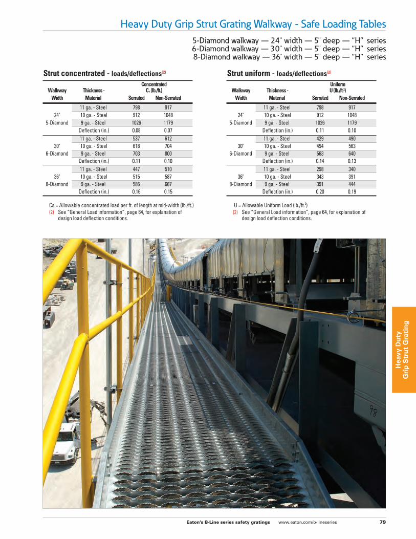
5-Diamond walkway — 24" width — 5" deep — “H” series 6-Diamond walkway — 30" width — 5" deep — “H” series 8-Diamond walkway — 36" width — 5" deep — “H” series
Heavy Duty Grip Strut Grating Walkway - Safe Loading Tables
Strut concentrated - loads/deflections(2)
Concentrated Walkway Thickness - Cs (lb./ft.) Width Material Serrated Non-Serrated
11 ga. - Steel 798 917 24" 10 ga. - Steel 912 1048 5-Diamond 9 ga. - Steel 1026 1179 Deflection (in.) 0.08 0.07 11 ga. - Steel 537 612 30" 10 ga. - Steel 618 704 6-Diamond 9 ga. - Steel 703 800 Deflection (in.) 0.11 0.10 11 ga. - Steel 447 510 36" 10 ga. - Steel 515 587 8-Diamond 9 ga. - Steel 586 667 Deflection (in.) 0.16 0.15
Cs = Allowable concentrated load per ft. of length at mid-width (lb./ft.) (2) See “General Load information”, page 64, for explanation of design load deflection conditions.
Strut uniform - loads/deflections(2)
Uniform Walkway Thickness - U (lb./ft.2) Width Material Serrated Non-Serrated
11 ga. - Steel 798 917 24" 10 ga. - Steel 912 1048 5-Diamond 9 ga. - Steel 1026 1179 Deflection (in.) 0.11 0.10 11 ga. - Steel 429 490 30" 10 ga. - Steel 494 563 6-Diamond 9 ga. - Steel 563 640 Deflection (in.) 0.14 0.13 11 ga. - Steel 298 340 36" 10 ga. - Steel 343 391 8-Diamond 9 ga. - Steel 391 444 Deflection (in.) 0.20 0.19
U = Allowable Uniform Load (lb./ft.2) (2) See “General Load information”, page 64, for explanation of design load deflection conditions.
Eaton’s B-Line series safety gratings www.eaton.com/b-lineseries 80
Heavy D
uty
Grip
Stru
t Gratin
g
Heavy Duty Grip Strut - Accessories
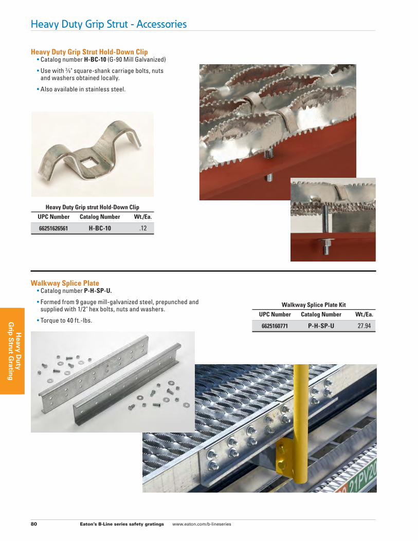
Heavy Duty Grip Strut Hold-Down Clip • Catalog number H-BC-10 (G-90 Mill Galvanized)
• Use with 3⁄8" square-shank carriage bolts, nuts and washers obtained locally.
• Also available in stainless steel.
Walkway Splice Plate • Catalog number P-H-SP-U.
• Formed from 9 gauge mill-galvanized steel, prepunched and supplied with 1/2" hex bolts, nuts and washers.
• Torque to 40 ft.-lbs.
Walkway Splice Plate Kit
UPC Number Catalog Number Wt./Ea.
6625160771 P-H-SP-U 27.94
Heavy Duty Grip strut Hold-Down Clip
UPC Number Catalog Number Wt./Ea.
66251626561 H-BC-10 .12
Eaton’s B-Line series safety gratings www.eaton.com/b-lineseries 81
Hea
vy D
uty
G
rip
Str
ut
Gra
tin
g
Heavy Duty Grip Strut - Accessories
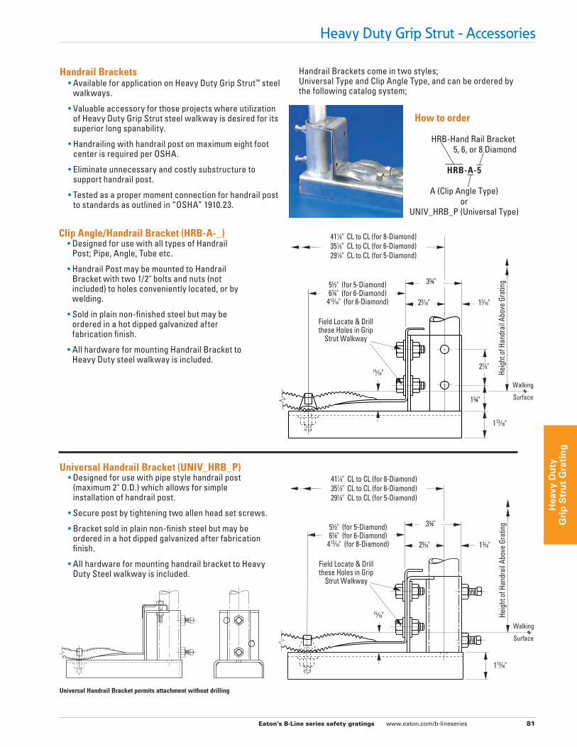
Universal Handrail Bracket (UNIV_HRB_P) • Designed for use with pipe style handrail post
(maximum 2" O.D.) which allows for simple installation of handrail post.
• Secure post by tightening two allen head set screws.
• Bracket sold in plain non-finish steel but may be ordered in a hot dipped galvanized after fabrication finish.
• All hardware for mounting handrail bracket to Heavy Duty Steel walkway is included.
Clip Angle/Handrail Bracket (HRB-A-_) • Designed for use with all types of Handrail
Post; Pipe, Angle, Tube etc.
• Handrail Post may be mounted to Handrail Bracket with two 1/2" bolts and nuts (not included) to holes conveniently located, or by welding.
• Sold in plain non-finished steel but may be ordered in a hot dipped galvanized after fabrication finish.
• All hardware for mounting Handrail Bracket to Heavy Duty steel walkway is included.
Handrail Brackets • Available for application on Heavy Duty Grip Strut™ steel
walkways.
• Valuable accessory for those projects where utilization of Heavy Duty Grip Strut steel walkway is desired for its superior long spanability.
• Handrailing with handrail post on maximum eight foot center is required per OSHA.
• Eliminate unnecessary and costly substructure to support handrail post.
• Tested as a proper moment connection for handrail post to standards as outlined in “OSHA” 1910.23.
Handrail Brackets come in two styles; Universal Type and Clip Angle Type, and can be ordered by the following catalog system;
How to order
HRB-Hand Rail Bracket 5, 6, or 8 Diamond
HRB-A-5
A (Clip Angle Type) or UNIV_HRB_P (Universal Type)
411⁄8" CL to CL (for 8-Diamond)351⁄8" CL to CL (for 6-Diamond)291⁄8" CL to CL (for 5-Diamond)
51/2" (for 5-Diamond)61/4" (for 6-Diamond)
413⁄16" (for 8-Diamond)
Field Locate & Drillthese Holes in Grip
Strut Walkway
Heig
ht o
f Han
drai
l Abo
ve G
ratin
g
Walking
Surface
33/4"
29⁄16" 13⁄16"
113⁄16"
15⁄16"
411⁄8" CL to CL (for 8-Diamond)351⁄8" CL to CL (for 6-Diamond)291⁄8" CL to CL (for 5-Diamond)
51/2" (for 5-Diamond)61/4" (for 6-Diamond)
413⁄16" (for 8-Diamond)
Field Locate & Drillthese Holes in Grip
Strut Walkway
Heig
ht o
f Han
drai
l Abo
ve G
ratin
g
Walking
Surface
33/4"
29⁄16" 13⁄16"
113⁄16"
13/4"
25⁄8" 15⁄16"
UNIV HRB P - Clamped UNIV HRB P - Bolted
HRB A
Universal Handrail Bracket permits attachment without drilling
Eaton’s B-Line series safety gratings www.eaton.com/b-lineseries 82
Heavy D
uty
Grip
Stru
t Gratin
g
Heavy Duty Grip Strut Grating - Stair Treads
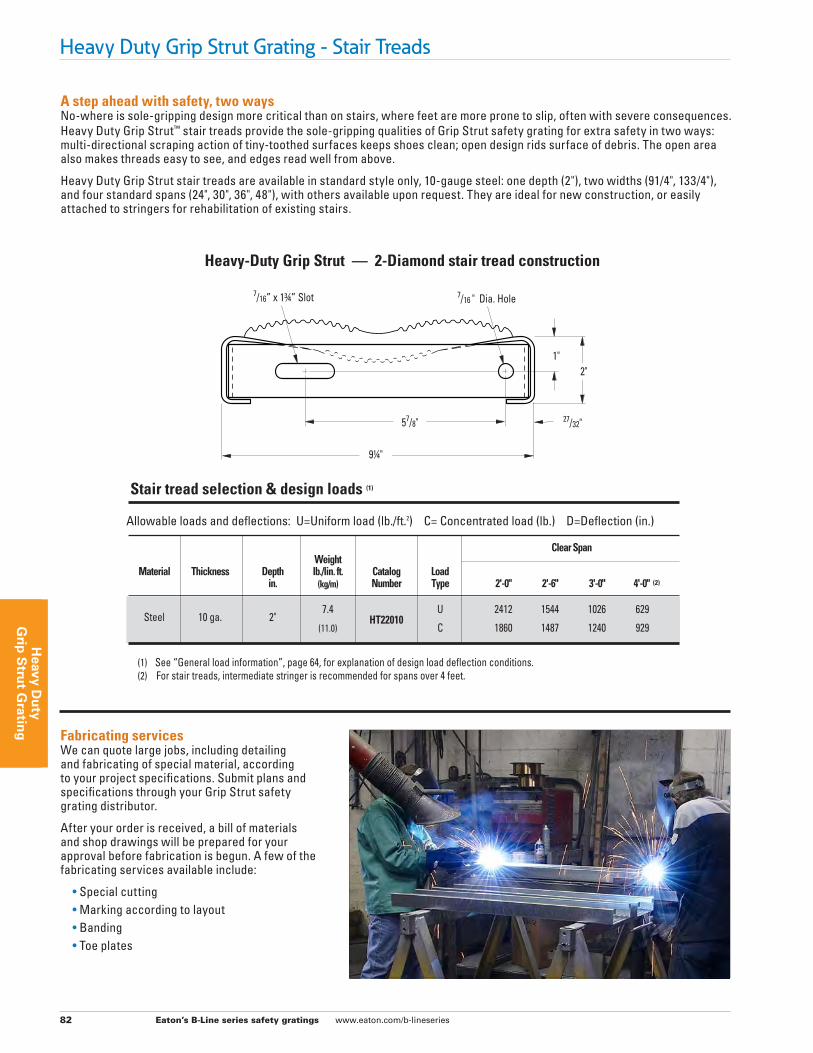
Heavy-Duty Grip Strut — 2-Diamond stair tread construction
A step ahead with safety, two waysNo-where is sole-gripping design more critical than on stairs, where feet are more prone to slip, often with severe consequences. Heavy Duty Grip Strut™ stair treads provide the sole-gripping qualities of Grip Strut safety grating for extra safety in two ways: multi-directional scraping action of tiny-toothed surfaces keeps shoes clean; open design rids surface of debris. The open area also makes threads easy to see, and edges read well from above.
Heavy Duty Grip Strut stair treads are available in standard style only, 10-gauge steel: one depth (2"), two widths (91/4", 133/4"), and four standard spans (24", 30", 36", 48"), with others available upon request. They are ideal for new construction, or easily attached to stringers for rehabilitation of existing stairs.
Allowable loads and deflections: U=Uniform load (lb./ft.2) C= Concentrated load (lb.) D=Deflection (in.) Clear Span Weight Material Thickness Depth lb./lin. ft. Catalog Load in. (kg/m) Number Type 2'-0" 2'-6" 3'-0" 4'-0" (2)
Steel 10 ga. 2"
7.4 U 2412 1544 1026 629
(11.0) HT22010
C 1860 1487 1240 929
(1) See “General load information”, page 64, for explanation of design load deflection conditions. (2) For stair treads, intermediate stringer is recommended for spans over 4 feet.
Stair tread selection & design loads (1)
1" 2"
7/16 " Dia. Hole7/16” x 13/4” Slot
27/32" 57/8"
91/4"
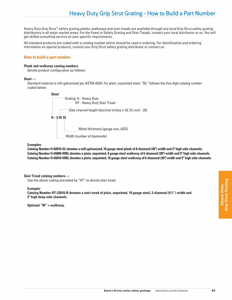
Fabricating servicesWe can quote large jobs, including detailing and fabricating of special material, according to your project specifications. Submit plans and specifications through your Grip Strut safety grating distributor.
After your order is received, a bill of materials and shop drawings will be prepared for your approval before fabrication is begun. A few of the fabricating services available include:
• Special cutting • Marking according to layout • Banding • Toe plates
Eaton’s B-Line series safety gratings www.eaton.com/b-lineseries 83
Hea
vy D
uty
G
rip
Str
ut
Gra
tin
g
Heavy Duty Grip Strut Grating - How to Build a Part Number
Heavy Duty Grip Strut™ safety grating planks, walkways and stair treads are available through any local Grip Strut safety grating distributors in all major market areas. For the finest in Safety Grating and Stair Treads, contact your local distributor or us. You will get skilled consulting service on your specific requirements.
All standard products are coded with a catalog number which should be used in ordering. For identification and ordering information on special products, consult your Grip Strut safety grating distributor or contact us.
How to build a part number:
Plank and walkway catalog numbers denote product configuration as follows:
Steel — Standard material is mill-galvanized per ASTM A525. For plain, unpainted steel, “BL” follows the five-digit catalog number coded below.
Steel Grating: H - Heavy Duty HT - Heavy Duty Stair Tread
Side channel height (decimal inches x 10; 21/2 inch - 25)
H - 3 25 10
Metal thickness (gauge size, ASG)
Width (number of diamonds)
Examples: Catalog Number H-82010-GL denotes a mill-galvanized, 10 gauge steel plank of 8-diamond (36") width and 2" high side channels; Catalog Number H-65009-WBL denotes a plain, unpainted, 9 gauge steel walkway of 6-diamond (30") width and 5" high side channels. Catalog Number H-65010-WBL denotes a plain, unpainted, 10 gauge steel walkway of 6-diamond (30") width and 5" high side channels.
Stair Tread catalog numbers — Use the above coding preceded by “HT” to denote stair tread.
Example: Catalog Number HT-22010-B denotes a stair tread of plain, unpainted, 10 gauge steel, 2-diamond (9 1/4" ) width and 2" high deep side channels.
Optional “W” = walkway.
Eaton’s B-Line series safety gratings www.eaton.com/b-lineseries 84
Heavy D
uty
Grip
Stru
t Gratin
g
Notes to architect
Heavy Duty Grip Strut Grating - Specifications
1. These specifications are presented as a general guide to the architect or structural engineer in preparing project specifications. Allowable loads, spans, and other limiting conditions presented in this catalog are product data for use in design and construction. These products must not be used without prior structural design by a qualified engineer or architect.
2. Grip Strut safety gratings are intended for general purpose use in plants and process facilities by industry, commerce, and public utilities.
Grip Strut safety grating stair treads are intended for utility stairs and fire escapes in commercial, industrial buildings where local code permits. They are not intended for staircases and other areas used regularly by the general public where flat closed surfaces are desired.
3. All supports should 11/2" minimum bearing surface free of burrs, bridging, welds and other irregularities. (Note: When using Butterfly Anchor Clips “H-BC-10” it is advisable to provide a minimum of 3" for bearing per support per grating).
4. Random-, diagonal- or circular-cut exposed edges should be reinforced with a bar of grating thickness (minimum 1⁄ 8") and width equal to overall grating depth, welded at contact points of the designer’s discretion.
5. Bolted connections, except stair or ladder tread attachment to stringers, may be replaced by welded connections of equal or greater strength.
Part 1: General
1.1 Scope The contractor shall furnish and install Grip Strut grating and
stair treads, as specified, in all areas where shown on the drawings.
1.2 Qualifications All Grip Strut grating, stair tread and accessories, unless
otherwise indicated, shall be manufactured by Eaton, and shall be installed in accordance with its current recommendations.
1.3 Submittals The contractor shall furnish shop drawings of grating layout,
framing and supports, unit dimensions and sections, fastener and weld types and locations.
1.4 Storage and Handling All materials shall be stored and handled to avoid damage.
Damaged or deteriorated materials shall be removed from the premises.
Part 2: Products
2.1 Gratings a. Type: Heavy Duty Grip Strut™ safety grating (plank)
(walkway). b. Metal: (carbon steel). c. Finish: mill-galvanized before fabrication, ASTM A653
G-90 plain, unpainted, and oiled (HRP&O). d. Metal gauge: 11-ga., 10-ga., 9-ga. (ASG steel). e. Section width: 91/4", 133/4", 231/4", 273/4", 36" (plank); 24", 30",
36" (walkway). f. Side channel height: 2" , 21/2", 3", 4" (plank); 5" (walkway),
also Canadian OH & S compliant. g. Standard lengths: 10'-0" , 12'-0" , 24'-0" (walkway); 10'-0",
12-0" , special order (plank). h. Opening diamond: “H” series, 37/8" x 11/4" wide (grating
surface-projected dimensions). i. Reticulated pattern: 15⁄16" high, minimum of 500 teeth per
square foot. j. Slip resistance: Complies with Federal Specification RR-
G-1602D standards. k. Surface texture: Standard serrated, non-serrated, and
reduced opening.
Eaton’s B-Line series safety gratings www.eaton.com/b-lineseries 85
Hea
vy D
uty
G
rip
Str
ut
Gra
tin
g
Heavy Duty Grip Strut Grating - Specifications
2.2 Stair Treads a. Type: Heavy Duty Grip Strut™ stair tread. b. Metal: carbon steel - ASTM A653 G-90. c. Finish: mill-galvanized before fabrication, ASTM A525
plain, unpainted, and oiled (HRP&O). d. Metal thickness: 10-ga. (ASG, steel). e. Section width: 91/2" . f. Side channel height: 2" . g. Standard lengths: (2", 21/2", 36", 4" (nominal and actual). h. Opening diamond: “H” Series, 37/8" x 11/4" wide (grating
surface-projected dimensions). i. Open area: 52%. j. Reticulated pattern: 15⁄16" high, minimum of 500 teeth per
square foot. k. Slip resistance: Complies with Federal Specification RR-
G-1602D standards.
2.3 Accessories Heavy Duty Grip Strut hold-down clip, G-90 mill galvanized,
Catalog number H-BC-10. (Use with 3/8" square-shank carriage bolts, nuts, and washers obtained locally). Also available in stainless steel.
Handrail bracket - hardware to attach bracket to walkway is supplied. Optional hot dipped galvanized after fabrication is available per request.
Heavy Duty Grip Strut splice plate (P-H-SP-U), 30" , 9 gauge mill-galvanized steel splice plate with bolts, hex nuts, and washers.
Part 3: Execution
3.1 Bearing surfaces Prior to grating installation, inspect supports for correct size,
layout and alignment, and verify that bearing surfaces are smooth and free of debris. Report in writing to the engineer or owner’s agent and defects so they can be corrected before grating is installed.
3.2 Grating installation Install grating in accordance with manufacturer's
recommendations and shop drawings. Position grating sections flat and square with ends bearing min. 11/2" on supporting structure; for sections over 12'-0" long, and when Heavy Duty Grip Strut hold-down clips are used, 3" minimum bearing surface is required. Bearing surface must be smooth, level, free of burrs, bridging, welds and other irregularities. Space grating sections a minimum 1/4" from vertical steel sections, and 1/2" from concrete walls. Allow maximum clearance between sections at joints of 1/4" at side channels, 3/8" at ends.
Band random-cut ends and diagonal or circular cut exposed edges with a bar of grating thickness (min. 1⁄8") and width equal to overall depth, welded at contact points of the designer's discretion.
3.3 Grating attachment Attach grating to supports without warp or deflection as
follows:
a. Single plank application: Secure plank ends to supporting members at every point of contact. At each end, use Heavy Duty Grip Strut hold-down clips with 3/8" square shank carriage bolts and nuts, or secure each side channel to support by 1⁄8" x 1" long fillet welds.
b. Multiple plank application: Secure perimeter plank to supporting members with 1⁄8" x 1" long fillet welds at every point of contact, intermediate grating sections with at least one attachment each end on alternate sides. When span exceeds 6'-0", attach side channels of adjacent planks together at mid-point of span for added rigidity. To joint adjacent planks together, weld them at 24" O.C. staggered top and bottom.
3.4 Stair Tread Installation Fasten Grip Strut stair treads shown on the drawings, or as
herein specified, to stair stringers with 3/8" x 1" machine bolts and nuts.
a. For stair treads, intermediate stringer is recommended for spans over 4 feet.