heating and air conditioning - york geothermal · heating and air conditioning affinity ... 104°f...
TRANSCRIPT
Heating and Air Conditioning
AFFINITYGEOTHERMAL HEAT PUMPSSINGLE SPEED HYDRONIC WITH VAPOR INJECTION
MODELS:YAWE040 - 066(3 THRU 5 NOMINAL TONS)
Due to continuous product improvement, specifications are subject to change without notice.
Visit us on the web at www.york-geothermal.com
Additional rating information can found atwww.ahridirectory.org
FOR DISTRIBUTION USE ONLY - NOT TO BE USED AT POINT OF RETAIL SALE
SPECIFICATION CATALOG


Table of Contents
AFFINITY SINGLE HYDRONIC WITH OPTIHEAT SPECIFICATION CATALOG
Model Nomenclature . . . . . . . . . . . . . . . . . . . . . . . . . . . . . . . . . . . . . . . . . . . . . . . . . . . . . . . . . . . . . . 5
AHRI/ISO 13256-2 Data. . . . . . . . . . . . . . . . . . . . . . . . . . . . . . . . . . . . . . . . . . . . . . . . . . . . . . . . . . . . 6
The York Affinity with OptiHeat . . . . . . . . . . . . . . . . . . . . . . . . . . . . . . . . . . . . . . . . . . . . . . . . . . . . . . . 8
Inside the York Affinity with OptiHeat . . . . . . . . . . . . . . . . . . . . . . . . . . . . . . . . . . . . . . . . . . . . . . . . . 10
Water Quality . . . . . . . . . . . . . . . . . . . . . . . . . . . . . . . . . . . . . . . . . . . . . . . . . . . . . . . . . . . . . . . . . . . .11
Aurora Control System . . . . . . . . . . . . . . . . . . . . . . . . . . . . . . . . . . . . . . . . . . . . . . . . . . . . . . . . . . . . 12
Application Notes . . . . . . . . . . . . . . . . . . . . . . . . . . . . . . . . . . . . . . . . . . . . . . . . . . . . . . . . . . . . . . . . 18
Dimensional Data . . . . . . . . . . . . . . . . . . . . . . . . . . . . . . . . . . . . . . . . . . . . . . . . . . . . . . . . . . . . . . . . 23
Physical Data . . . . . . . . . . . . . . . . . . . . . . . . . . . . . . . . . . . . . . . . . . . . . . . . . . . . . . . . . . . . . . . . . . . 24
Electrical Data . . . . . . . . . . . . . . . . . . . . . . . . . . . . . . . . . . . . . . . . . . . . . . . . . . . . . . . . . . . . . . . . . . 24
Antifreeze Correction . . . . . . . . . . . . . . . . . . . . . . . . . . . . . . . . . . . . . . . . . . . . . . . . . . . . . . . . . . . . . 25
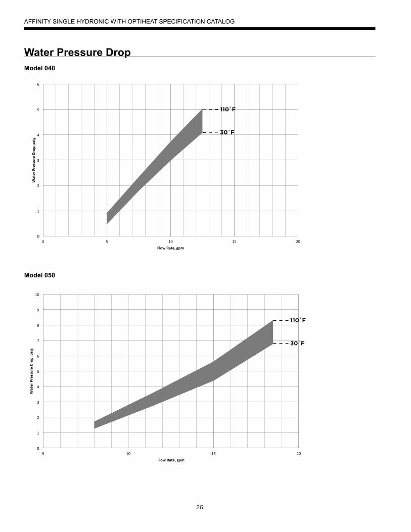
Water Pressure Drop . . . . . . . . . . . . . . . . . . . . . . . . . . . . . . . . . . . . . . . . . . . . . . . . . . . . . . . . . . . . . 26
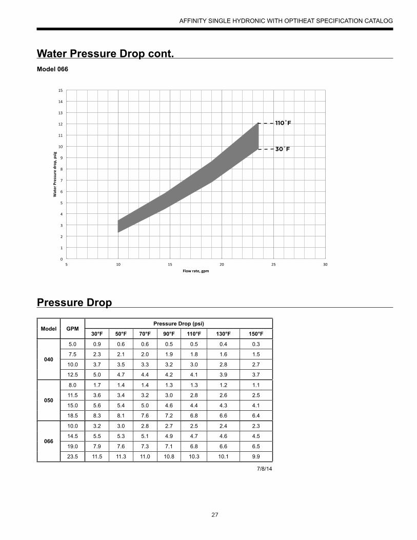
Pressure Drop . . . . . . . . . . . . . . . . . . . . . . . . . . . . . . . . . . . . . . . . . . . . . . . . . . . . . . . . . . . . . . . . . . 27
Heating Operating Envelope . . . . . . . . . . . . . . . . . . . . . . . . . . . . . . . . . . . . . . . . . . . . . . . . . . . . . . . 28
Reference Calculations . . . . . . . . . . . . . . . . . . . . . . . . . . . . . . . . . . . . . . . . . . . . . . . . . . . . . . . . . . . 29
Legend and Notes . . . . . . . . . . . . . . . . . . . . . . . . . . . . . . . . . . . . . . . . . . . . . . . . . . . . . . . . . . . . . . . 29
Performance Data . . . . . . . . . . . . . . . . . . . . . . . . . . . . . . . . . . . . . . . . . . . . . . . . . . . . . . . . . . . . . . . 30
Wiring Schematics . . . . . . . . . . . . . . . . . . . . . . . . . . . . . . . . . . . . . . . . . . . . . . . . . . . . . . . . . . . . . . . 36
Accessories and Options . . . . . . . . . . . . . . . . . . . . . . . . . . . . . . . . . . . . . . . . . . . . . . . . . . . . . . . . . . 38
Engineering Guide Specifications. . . . . . . . . . . . . . . . . . . . . . . . . . . . . . . . . . . . . . . . . . . . . . . . . . . . 40
Revision Guide . . . . . . . . . . . . . . . . . . . . . . . . . . . . . . . . . . . . . . . . . . . . . . . . . . . . . . . . . . . . . . . . . . 43

AFFINITY SINGLE HYDRONIC WITH OPTIHEAT SPECIFICATION CATALOG
4
York is proud to introduce the latest in geothermal heat pump technology by launching the Affinity with OptiHeat line of heat pumps which are the most efficient, Energy Star rated water to water heat pumps available on the market. OptiHeat utilizes Copeland vapor injection (VI) scroll compressor technology to provide optimal performance. Vapor injection theory uses an intermediate refrigerant heat exchanger to boost refrigeration capacity which increases overall heat pump efficiency. As the name OptiHeat implies, these units are optimized for heating performance. VI technology enables the heat pump an expanded operating range allowing leaving water temperatures of 150˚F. A 20˚F improvement over conventional systems while maintaining the same environmentally friendly R-410A refrigerant that is industry standard. Copeland VI compressors are specifically designed to operate under higher compression ratios which allows for higher temperature operation without sacrificing reliability. Affinity with OptiHeat units have been tested and approved for higher pressure operation per UL 1995 which is the standard for heating/cooling products in the United States.
OptiHeat units are equipped with electronic expansion valve controlled by the Aurora Base microprocessor to offer precise control of the vapor injection circuit. While the units are optimized for heating performance, cooling is still an option with reversible units. In the cooling mode, VI tech-nology is turned off to maintain simplicity and efficient performance.
1. Compressor: Vapor injected, single speed scroll, mounted on a double isolation system. Super Quiet Sound Package for improved noise reduction.
2. Water Lines: Flush mount connections allow one wrench leak-free connections without a back-up.3. Cabinet: Heavy gauge, environmentally responsible galvanized steel for maximum corrosion resistance. 4. Soft Start: IntelliStart™ reduces the amount of current needed to activate the unit by 60-70%. This helps alleviate light flicker, reduces start-
up noise and increases compressor life. Helpful in applications when units are to run off-the-grid. 5. ThermaShield™: Proprietary coating applied to water-to-refrigerant heat exchanger that protects against condensations in extended range
applications (below 50˚F).6. Discharge line mufflers to help quiet compressor discharge gas pulsations7. Electronic expansion valve for optimal superheat control of VI circuit8. Controls: Aurora Base Control with Aurora Expansion Board is standard.
Key Benefits: • 3 models sizes from 040-066 MBtu/hr. • Same cabinet footprint for easy retrofit of legacy product.• Field switchable control box
As a leader in the industry, York is dedicated to innovation, quality, and customer satisfaction. In fact, every unit built is exposed to a wide range of quality control procedures throughout the assembly process and is then subjected to a rigorous battery of computerized run tests to certify that it meets or exceeds performance standards for efficiency and safety, and will perform flawlessly at startup. As further affirmation of our quality stan-dards, each unit carries our exclusive Quality Assurance emblem, signed by the final test technician.
A f f i n i t y w i t h
Single Capacity Geothermal Heat Pump
Voltage Size040 050 066
208-230/60/1 ●● ● ● ● - Voltage available in this size ●● - Voltage and soft start available in this size
5
Model Nomenclature
5
AFFINITY SINGLE HYDRONIC WITH OPTIHEAT SPECIFICATION CATALOG
All Affinity with OptiHeat products are safety listed under UL1995 thru ETL and performance listed with AHRI in accordance with standard 13256-2. The Affinity with OptiHeat is also ENERGY STAR® rated.
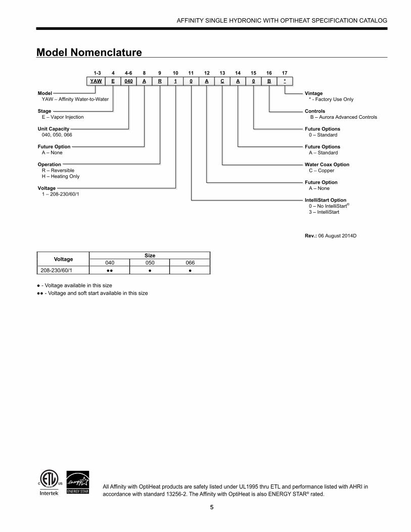
YAW E 040 A R 1 0 A C A 0 B *1-3 4 4-6 8 9 10 11 12 13 14 15 16 17
ModelYAW – Affinity Water-to-Water
StageE – Vapor Injection
Unit Capacity040, 050, 066
Future OptionA – None
OperationR – ReversibleH – Heating Only
Voltage1 – 208-230/60/1
Vintage* - Factory Use Only
ControlsB – Aurora Advanced Controls
Future Options0 – Standard
Future OptionsA – Standard
Water Coax OptionC – Copper
Future OptionA – None
IntelliStart Option0 – No IntelliStart®
3 – IntelliStart
Rev.: 06 August 2014D
AHRI/ISO 13256-2 Performance Ratings
6
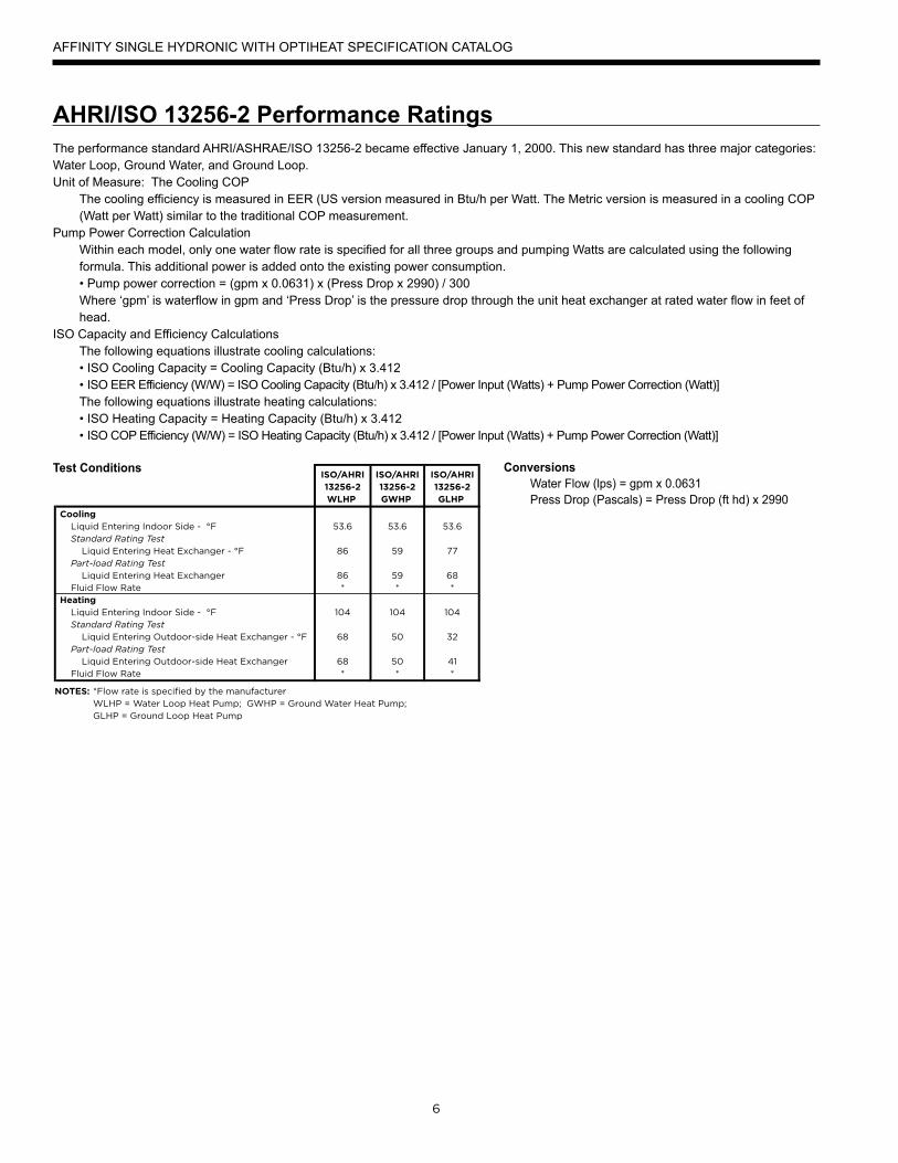
The performance standard AHRI/ASHRAE/ISO 13256-2 became effective January 1, 2000. This new standard has three major categories: Water Loop, Ground Water, and Ground Loop.Unit of Measure: The Cooling COP
The cooling efficiency is measured in EER (US version measured in Btu/h per Watt. The Metric version is measured in a cooling COP (Watt per Watt) similar to the traditional COP measurement.
Pump Power Correction CalculationWithin each model, only one water flow rate is specified for all three groups and pumping Watts are calculated using the following formula. This additional power is added onto the existing power consumption.• Pump power correction = (gpm x 0.0631) x (Press Drop x 2990) / 300Where ‘gpm’ is waterflow in gpm and ‘Press Drop’ is the pressure drop through the unit heat exchanger at rated water flow in feet of head.
ISO Capacity and Efficiency CalculationsThe following equations illustrate cooling calculations:• ISO Cooling Capacity = Cooling Capacity (Btu/h) x 3.412• ISO EER Efficiency (W/W) = ISO Cooling Capacity (Btu/h) x 3.412 / [Power Input (Watts) + Pump Power Correction (Watt)]The following equations illustrate heating calculations:• ISO Heating Capacity = Heating Capacity (Btu/h) x 3.412• ISO COP Efficiency (W/W) = ISO Heating Capacity (Btu/h) x 3.412 / [Power Input (Watts) + Pump Power Correction (Watt)]
Test Conditions Conversions Water Flow (lps) = gpm x 0.0631 Press Drop (Pascals) = Press Drop (ft hd) x 2990
AFFINITY SINGLE HYDRONIC WITH OPTIHEAT SPECIFICATION CATALOG
7
AHRI/ISO 13256-2 Performance Ratings
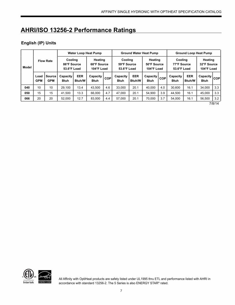
English (IP) Units
Model
Flow Rate
Water Loop Heat Pump Ground Water Heat Pump Ground Loop Heat Pump
Cooling 86°F Source 53.6°F Load
Heating 68°F Source 104°F Load
Cooling 59°F Source 53.6°F Load
Heating 50°F Source 104°F Load
Cooling 77°F Source 53.6°F Load
Heating 32°F Source 104°F Load
Load GPM
Source GPM
Capacity Btuh
EER Btuh/W
Capacity Btuh
COP Capacity
Btuh EER
Btuh/W Capacity
Btuh COP
Capacity Btuh
EER Btuh/W
Capacity Btuh
COP
040 10 10 29,100 13.4 43,500 4.6 33,000 20.1 40,000 4.0 30,600 16.1 34,000 3.3
050 15 15 41,500 13.3 66,000 4.7 47,000 20.1 54,900 3.9 44,500 16.1 45,000 3.3
066 20 20 52,000 12.7 83,000 4.4 57,000 20.1 70,000 3.7 54,000 16.1 56,500 3.27/8/14
AFFINITY SINGLE HYDRONIC WITH OPTIHEAT SPECIFICATION CATALOG
All Affinity with OptiHeat products are safety listed under UL1995 thru ETL and performance listed with AHRI in accordance with standard 13256-2. The 5 Series is also ENERGY STAR® rated.
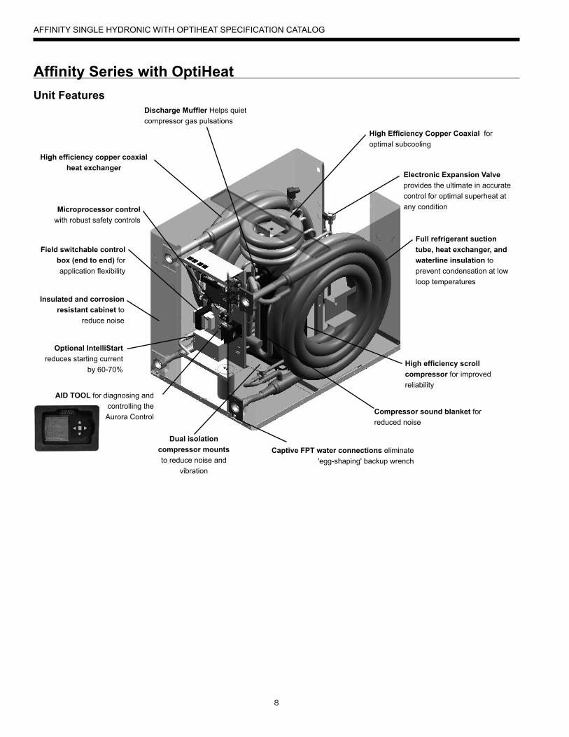
Optional IntelliStart reduces starting current
by 60-70%
AID TOOL for diagnosing and controlling the Aurora Control
Field switchable control box (end to end) for application flexibility
Insulated and corrosion resistant cabinet to
reduce noise
Microprocessor controlwith robust safety controls
Full refrigerant suction tube, heat exchanger, and waterline insulation to prevent condensation at low loop temperatures
Captive FPT water connections eliminate 'egg-shaping' backup wrench
High efficiency scroll compressor for improved reliability
Compressor sound blanket for reduced noise
Dual isolation compressor mounts to reduce noise and
vibration
Unit Features
High efficiency copper coaxial heat exchanger
Discharge Muffler Helps quiet compressor gas pulsations
Electronic Expansion Valve provides the ultimate in accurate control for optimal superheat at any condition
High Efficiency Copper Coaxial for optimal subcooling
8
AFFINITY SINGLE HYDRONIC WITH OPTIHEAT SPECIFICATION CATALOG
Affi nity Series with OptiHeat
9
Operating Efficiencies• Environmentally friendly R-410A refrigerant reduces ozone
depletion.• High-stability bidirectional expansion valve provides superior
performance.• Efficient scroll compressor operates quietly.• Oversized coaxial tube water-to-refrigerant heat
exchanger increases efficiency.• Electronic expansion valve for VI circuits
Standard Features• Heavy gauge cabinet• Quiet scroll compressors in all models • All interior cabinet surfaces are insulated with 1⁄2 in. [12.7 mm] thick 1 1⁄2 lb. [681 g] density, surface coated, acoustic type glass fiber insulation. • Optional IntelliStart® to reduce starting current (208-230/60/1)• Field switchable control box• Ultra-compact cabinet• Multi-density laminate lined compressor blanket designed to
suppress low frequency noise.• Discharge line mufflers to help quiet compressor discharge gas
pulsations. • Removable compressor access panels.• Quick attach wiring harnesses are used throughout for
fast servicing.• High and low pressure refrigerant service ports.
Product Quality• Heavy-gauge steel cabinets are finished with a durable polyester
powder coat paint for long lasting beautyand service.
• All refrigerant brazing is performed in a nitrogen atmosphere.• Coaxial heat exchangers, refrigerant suction lines and all water
pipes are fully insulated to reduce condensation problems in low temperature operation.
• Computer controlled deep vacuum and refrigerant charging system.
• All joints are leak detected for maximum leak rate of less than 1⁄4 oz. per year.
• Computer bar code equipped assembly line ensures all components are correct.
• All units are computer run-tested with water to verify both function and performance.
• Safety features include high- and low-pressure refrigerant controls to protect the compressor.
Options and Accessories• Closed loop, source side, circulating pump kit• Closed loop, load side, circulating pump kit• Water connection kits• Geo-Storage Tank (80-120 Gal.)• IntelliStart• HydroZone, tank control with outdoor reset
Application Flexibility• Designed to operate with entering source temperature of 30°F
and leaving load temperatures of up to 150°F. See the capacity tables to see allowable operating conditions per model.
• Source side flow rates as low as 1.5 GPM/ton for well water, 50°F [10°C] min. EWT.
• Dedicated heating and heat pump models available.• Dedicated non-reversible models are shipped as
heating only.• Compact size allows installation in confined spaces.• Front or rear plumbing connections.
AFFINITY SINGLE HYDRONIC WITH OPTIHEAT SPECIFICATION CATALOG
Affinity Series OptiHeat cont.
10
AFFINITY SINGLE HYDRONIC WITH OPTIHEAT SPECIFICATION CATALOG
Inside the Affi nity Series with OptiHeatRefrigerantAffinity Series with OptiHeat products all feature zero ozone depletion and low global warming potential R-410A refrigerant.
CabinetAll units are constructed of corrosion resistant galvanized sheet metal with powder coat paint rated for more than 1000 hours of salt spray. Lift-out access panels provide access to the compressor section from two sides.
CompressorsHigh efficiency R-410A vapor injected, scroll compressors for each model sizes provides efficient yet reliable operation at all operating conditions.
Electrical BoxThe control panel is "field" movable from front to back for ease of application. Separate knockouts for low voltage, and two for power on, front and back, allow easy access to the control box. Large 75VA transformer assures adequate controls power for accessories.
Water ConnectionsFlush mount FPT water connection fittings allow one wrench leak-free connections and do not require a backup wrench. Factory installed water line thermistors can be viewed through the microprocessor interface tool.
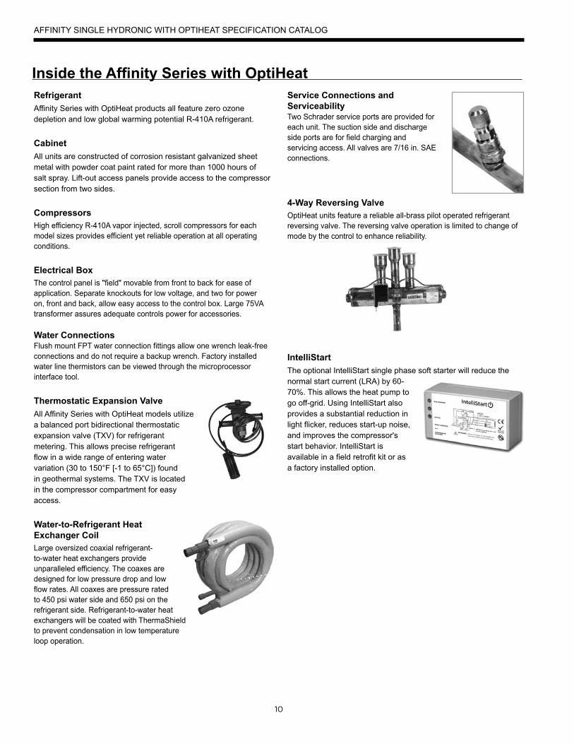
Thermostatic Expansion ValveAll Affinity Series with OptiHeat models utilize a balanced port bidirectional thermostatic expansion valve (TXV) for refrigerant metering. This allows precise refrigerant flow in a wide range of entering water variation (30 to 150°F [-1 to 65°C]) found in geothermal systems. The TXV is located in the compressor compartment for easy access.
Water-to-Refrigerant Heat Exchanger CoilLarge oversized coaxial refrigerant-to-water heat exchangers provide unparalleled efficiency. The coaxes are designed for low pressure drop and low flow rates. All coaxes are pressure rated to 450 psi water side and 650 psi on the refrigerant side. Refrigerant-to-water heat exchangers will be coated with ThermaShield to prevent condensation in low temperature loop operation.
Service Connections and ServiceabilityTwo Schrader service ports are provided for each unit. The suction side and discharge side ports are for field charging and servicing access. All valves are 7/16 in. SAE connections.
4-Way Reversing ValveOptiHeat units feature a reliable all-brass pilot operated refrigerant reversing valve. The reversing valve operation is limited to change of mode by the control to enhance reliability.
IntelliStartThe optional IntelliStart single phase soft starter will reduce the normal start current (LRA) by 60-70%. This allows the heat pump to go off-grid. Using IntelliStart also provides a substantial reduction in light flicker, reduces start-up noise, and improves the compressor's start behavior. IntelliStart is available in a field retrofit kit or as a factory installed option.
11
GeneralWater-to-water heat pumps may be successfully applied in a wide range of residential and light commercial applications. It is the responsibility of the system designer and installing contractor to ensure that acceptable water quality is present and that all applicable codes have been met in these installations. Failure to adhere to the guidelines in the water quality table could result in loss of warranty.
Water TreatmentThe use of improperly treated or untreated water in this equipment may result in scaling, erosion, corrosion, algae or slime. The services of a qualified water treatment specialist should be engaged to determine what treatment, if any, is required. The product warranty specifically excludes liability for corrosion, erosion or deterioration of equipment.
The heat exchangers and water lines in the units are copper tube. There may be other materials in the building’s piping system that the designer may need to take into consideration when deciding the parameters of the water quality.
If an antifreeze or water treatment solution is to be used, the designer should confirm it does not have a detrimental effect on the materials in the system.
Water QualityContaminated WaterIn applications where the water quality cannot be held to prescribed limits, the use of a secondary or intermediate heat exchanger is recommended to separate the unit from the contaminated water.
The following table outlines the water quality guidelines for unit heat exchangers. If these conditions are exceeded, a secondary heat exchanger is required. Failure to supply a secondary heat exchanger where needed will result in a warranty exclusion for primary heat exchanger corrosion or failure.
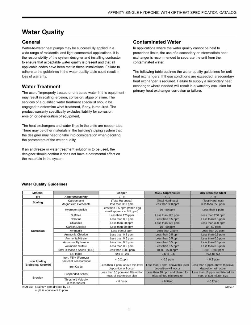
Water Quality Guidelines
Material Copper 90/10 Cupronickel 316 Stainless SteelpH Acidity/Alkalinity 7 - 9 7 - 9 7 - 9
Scaling Calcium andMagnesium Carbonate
(Total Hardness)less than 350 ppm
(Total Hardness)less than 350 ppm
(Total Hardness)less than 350 ppm
Corrosion
Hydrogen Sulfide Less than 0.5 ppm (rotten egg smell appears at 0.5 ppm) 10 - 50 ppm Less than 1 ppm
Sulfates Less than 125 ppm Less than 125 ppm Less than 200 ppmChlorine Less than 0.5 ppm Less than 0.5 ppm Less than 0.5 ppmChlorides Less than 20 ppm Less than 125 ppm Less than 300 ppm
Carbon Dioxide Less than 50 ppm 10 - 50 ppm 10 - 50 ppmAmmonia Less than 2 ppm Less than 2 ppm Less than 20 ppm
Ammonia Chloride Less than 0.5 ppm Less than 0.5 ppm Less than 0.5 ppmAmmonia Nitrate Less than 0.5 ppm Less than 0.5 ppm Less than 0.5 ppm
Ammonia Hydroxide Less than 0.5 ppm Less than 0.5 ppm Less than 0.5 ppmAmmonia Sulfate Less than 0.5 ppm Less than 0.5 ppm Less than 0.5 ppm
Total Dissolved Solids (TDS) Less than 1000 ppm 1000 - 1500 ppm 1000 - 1500 ppmLSI Index +0.5 to -0.5 +0.5 to -0.5 +0.5 to -0.5
Iron Fouling(Biological Growth)
Iron, FE2+ (Ferrous)Bacterial Iron Potential < 0.2 ppm < 0.2 ppm < 0.2 ppm
Iron Oxide Less than 1 ppm, above this level deposition will occur
Less than 1 ppm, above this level deposition will occur
Less than 1 ppm, above this level deposition will occur
ErosionSuspended Solids Less than 10 ppm and filtered for
max. of 600 micron sizeLess than 10 ppm and filtered for
max. of 600 micron sizeLess than 10 ppm and filtered for
max. of 600 micron sizeThreshold Velocity
(Fresh Water) < 6 ft/sec < 6 ft/sec < 6 ft/sec
NOTES: Grains = ppm divided by 17mg/L is equivalent to ppm
7/08/14
AFFINITY SINGLE HYDRONIC WITH OPTIHEAT SPECIFICATION CATALOG

12
The Aurora™ Control System
Aurora Control Features Description Aurora 'Advanced'
Microprocessor Compressor Control Microprocessor control of compressor for timings with FP1, HP, LP, Condensate, assignable Acc relay •
Advanced Microprocessor Features Smart Grid, Home Automation Alarm Inputs, and Accessory2 Relay (HRV/ERV) •
Advanced Speed Pump Control Microprocessor and separate power relay for loop pump and inline circuit breakers and loop pump slaving. •
Variable Speed Pump Capable of setup, monitoring and controlling a variable speed flow center. •
Smart Grid/Utility Input Allows simple input to externally enable of occupied/unoccupied mode for basic utility time of use programs. Dry Contact x1
Home Automation Alarm InputAllows simple input to signal sump, security, or smoke/CO sensor alarms from other home automation or security systems. The two inputs can be field configured to a number of options and logic.
Dry Contactx2
HAN/Smart Grid Com(AWL and Portal) Kit
Allows direct communication of the Aurora to Smart Meters, Home Automation Network and Internet. Optional AWL
Aurora ‘Base’ ControlThe Aurora ‘Base’ Control (ABC) System is a complete residential and commercial comfort system that brings all aspects of the HVAC system into one cohesive module network. The ABC features microprocessor control and HP, LP, freeze detection, over/under voltage faults.
Aurora uses the Modbus communication protocol to communicate between modules. Each module contains the logic to control all features that are connected to the module. The Aurora ‘Base’ Control (ABC) has two Modbus channels. The first channel is configured as a master for connecting to devices such as a expansion board, or other slave devices. The second channel is configured as a slave for connecting the Aurora Interface Diagnostics Tool (AID Tool).
Aurora ‘Advanced’ ControlThe Aurora ‘Advanced’ Control expands on the capability of the Aurora ‘Base’ Control (ABC) System by adding the Aurora Expansion Board (AXB). The additional features include loop pump slaving and variable speed pump capability. The AXB also features a second field configurable accessory relay, and two home automation inputs that are AID configurable for different types of alarms from sump pumps to home security. The Smart Grid input is AID configurable with many options to react to Utility controlled relay operation for ON Peak optimization.
Service Device Description Aurora ‘Base’ Aurora 'Advanced'
Aurora Interface and Diagnostics (AID) Tool
Allows setup, monitoring and troubleshooting of anyAurora Control.
NOTE: Although the ABC has basic compatibility with all Aurora, new product features may not be available on older AID Tools. To simplify the basic compatibility ensure the version of AID is at least the same or greater than the ABC software version.
For Service(Ver. 1.xx or greater)
For Service(Ver. 2.xx or greater)
AFFINITY SINGLE HYDRONIC WITH OPTIHEAT SPECIFICATION CATALOG
13
The Aurora™ Control System cont..
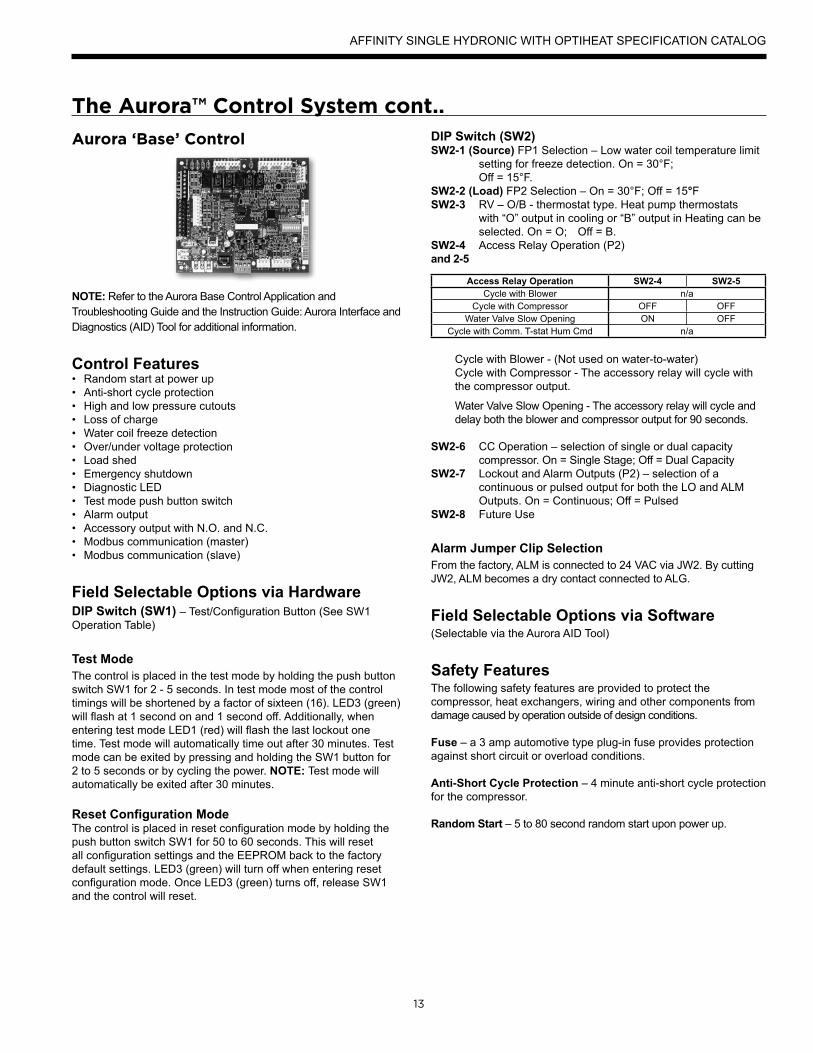
Aurora ‘Base’ Control
NOTE: Refer to the Aurora Base Control Application and Troubleshooting Guide and the Instruction Guide: Aurora Interface and Diagnostics (AID) Tool for additional information.
Control Features• Random start at power up• Anti-short cycle protection• High and low pressure cutouts• Loss of charge• Water coil freeze detection• Over/under voltage protection• Load shed• Emergency shutdown• Diagnostic LED• Test mode push button switch• Alarm output• Accessory output with N.O. and N.C.• Modbus communication (master)• Modbus communication (slave)
Field Selectable Options via HardwareDIP Switch (SW1) – Test/Configuration Button (See SW1 Operation Table)
Test ModeThe control is placed in the test mode by holding the push button switch SW1 for 2 - 5 seconds. In test mode most of the control timings will be shortened by a factor of sixteen (16). LED3 (green) will flash at 1 second on and 1 second off. Additionally, when entering test mode LED1 (red) will flash the last lockout one time. Test mode will automatically time out after 30 minutes. Test mode can be exited by pressing and holding the SW1 button for 2 to 5 seconds or by cycling the power. NOTE: Test mode will automatically be exited after 30 minutes.
Reset Configuration ModeThe control is placed in reset configuration mode by holding the push button switch SW1 for 50 to 60 seconds. This will reset all configuration settings and the EEPROM back to the factory default settings. LED3 (green) will turn off when entering reset configuration mode. Once LED3 (green) turns off, release SW1 and the control will reset.
DIP Switch (SW2) SW2-1 (Source) FP1 Selection – Low water coil temperature limit
setting for freeze detection. On = 30°F; Off = 15°F.SW2-2 (Load) FP2 Selection – On = 30°F; Off = 15°FSW2-3 RV – O/B - thermostat type. Heat pump thermostats
with “O” output in cooling or “B” output in Heating can be selected. On = O; Off = B.
SW2-4 Access Relay Operation (P2)and 2-5
Access Relay Operation SW2-4 SW2-5Cycle with Blower n/a
Cycle with Compressor OFF OFFWater Valve Slow Opening ON OFF
Cycle with Comm. T-stat Hum Cmd n/a
Cycle with Blower - (Not used on water-to-water)Cycle with Compressor - The accessory relay will cycle with the compressor output.
Water Valve Slow Opening - The accessory relay will cycle and delay both the blower and compressor output for 90 seconds.
SW2-6 CC Operation – selection of single or dual capacity compressor. On = Single Stage; Off = Dual Capacity
SW2-7 Lockout and Alarm Outputs (P2) – selection of a continuous or pulsed output for both the LO and ALM Outputs. On = Continuous; Off = Pulsed
SW2-8 Future Use
Alarm Jumper Clip SelectionFrom the factory, ALM is connected to 24 VAC via JW2. By cutting JW2, ALM becomes a dry contact connected to ALG.
Field Selectable Options via Software(Selectable via the Aurora AID Tool)
Safety FeaturesThe following safety features are provided to protect the compressor, heat exchangers, wiring and other components from damage caused by operation outside of design conditions.
Fuse – a 3 amp automotive type plug-in fuse provides protection against short circuit or overload conditions.
Anti-Short Cycle Protection – 4 minute anti-short cycle protection for the compressor.
Random Start – 5 to 80 second random start upon power up.
AFFINITY SINGLE HYDRONIC WITH OPTIHEAT SPECIFICATION CATALOG

14
The Aurora™ Control System cont..
Fault Retry – in the fault condition, the control will stage off the outputs and then “try again” to satisfy the thermostat Y input call. Once the thermostat input calls are satisfied, the control will continue on as if no fault occurred. If 3 consecutive faults occur without satisfying the thermostat Y input call, then the control will go to Lockout mode.
Lockout – The Alarm output (ALM) and Lockout output (L) will be turned on. The fault type identification display LED1 (Red) shall flash the fault code. To reset lockout conditions with SW2-8 On, thermostat inputs “Y1”, “Y2”, and “W” must be removed for at least 3 seconds. To reset lockout conditions with SW2-8 Off, thermostat inputs “Y1”, “Y2”, “W”, and “DH” must be removed for at least 3 seconds. Lockout may also be reset by turning power off for at least 30 seconds or by enabling the emergency shutdown input for at least 3 seconds.
High Pressure – fault is recognized when the Normally Closed High Pressure Switch, P4-9/10 opens, no matter how momentarily. The High Pressure Switch is electrically in series with the Compressor Contactor and serves as a hard-wired limit switch if an overpressure condition should occur.
Low Pressure - fault is recognized when the Normally Closed Low Pressure Switch, P4-7/8 is continuously open for 30 seconds. Closure of the LPS any time during the 30 second recognition time restarts the 30 second continuous open requirement. A continuously open LPS shall not be recognized during the 2 minute startup bypass time.
Loss of Charge – fault is recognized when the Normally Closed Low Pressure Switch, P4-7/8 is open prior to the compressor starting.
Freeze Detection (Source Coax) - set points shall be either 30°F or 15°F. When the thermistor temperature drops below the selected set point, the control shall begin counting down the 30 seconds delay. If the thermistor value rises above the selected set point, then the count should reset. The resistance value must remain below the selected set point for the entire length of the appropriate delay to be recognized as a fault. This fault will be ignored for the initial 2 minutes of the compressor run time.
Freeze Detection (Load Coax) - uses the FP2 input to protect against ice formation on the coax. The FP2 input will operate exactly like FP1 except that the set point is 30 degrees and is not field adjustable.
Over/Under Voltage Shutdown - An over/under voltage condition exists when the control voltage is outside the range of 18 VAC to 30 VAC. If the over/under voltage shutdown lasts for 15 minutes, the lockout and alarm relay will be energized. Over/under voltage shutdown is self-resetting in that if the voltage comes back within range of 18 VAC to 30 VAC for at least 0.5 seconds, then normal operation is restored.
Operation DescriptionPower Up - The unit will not operate until all the inputs and safety controls are checked for normal conditions. The unit has a 5 to 80 second random start delay at power up. Then the compressor has a 4 minute anti-short cycle delay after the random start delay.
Standby In standby mode, Y1, Y2, W, DH, and G are not active. Input O may be active. The blower and compressor will be off.
Heating OperationHeating, 1st Stage (Y1) - The compressor is energized 10 seconds after the Y1 input is received.
Cooling OperationIn all cooling operations, the reversing valve directly tracks the O input. Thus, anytime the O input is present, the reversing valve will be energized.
Cooling, 1st Stage (Y1, O) - The compressor is energized 10 seconds after the Y1 input is received.
Emergency Shutdown - Four (4) seconds after a valid ES input, P2-7 is present, all control outputs will be turned off and remain off until the emergency shutdown input is no longer present. The first time that the compressor is started after the control exits the emergency shutdown mode, there will be an anti-short cycle delay followed by a random start delay. Input must be tied to common to activate.
Load Shed - The LS input disables all outputs with the exception of the blower output. When the LS input has been cleared, the anti-short cycle timer and random start timer will be initiated. Input must be tied to common to activate.
AFFINITY SINGLE HYDRONIC WITH OPTIHEAT SPECIFICATION CATALOG

15
CC2
Fact
ory
Fault
ALG
ALM
LSES
ACC
c
Status
AuroraTM BaseControl
RV – K1
CC
2
CC – K2
CC Hi – K3
Fan – K4
Alarm – K5
Acc – K6
ACC
no
ACC
nc
O/BCRLO G Y1 Y2 W DH
3A-F
use
O/BCRLO G Y1 Y2 W DH
LOG
HICCGCCFGFR
HPHPLP
FP2FP2FP1
REVREV
CFM
PWM
ECM PWM
Fact
ory
Factory Fan Connection
R R
CC
C
C
R
(-)
(+)
RS
485
EH2C
EH1C
CO
(+)(-)RC
RS4
85Ex
pFa
ctor
y
Com1
Com2
Config
G
G
G
YR
SW1 Test
FP1 – 15oF/30oF
JW2 - Alarm
P11
P5
P2 P1
P8
P7
P9
P6
P3
SW2
P13P4 FP2 – 15oF/30oF
RV – B/O
ACC – Dip 1
ACC – Dip 2
CC – Dual/SingleL – Pulse/Continuous
Reheat/Normal
Fact
ory
Use
Field ConnectionsField Connections
C
LP
FP1
F
CC
G
Y1
1
2
3
4
5
6
7
8
Off On
N/A
RS4
85 N
ET
EH1LED 1
LED 3
LED 2
LED 5
LED 4
5.0 in.
6.25
in.
5.5 in.
5.75
in.
ABC Control Board LayoutAurora ‘Base’ Control LED DisplaysThese three LEDs display the status, configuration, and fault codes for the control. These can also be read in plain English via the Aurora AID Tool.
Status LED (LED3, Green)Description of Operation Fault LED, Green
Normal Mode ONControl is Non-functional OFFTest Mode Slow FlashLockout Active Fast FlashDehumidification Mode Flash Code 2(Future Use) Flash Code 3(Future Use) Flash Code 4Load Shed Flash Code 5ESD Flash Code 6(Future Use) Flash Code 7
Aurora Interface and Diagnostics (AID) ToolThe Aurora Interface and Diagnostics (AID) Tool is a device that is a member of the Aurora network. The AID Tool is used to troubleshoot equipment which uses the Aurora control via Modbus RTU communication. The AID Tool provides diagnostics, fault management, ECM setup, and system configuration capabilities to the Aurora family of controls. An AID Tool is recommended, although not required, for ECM airflow settings. The AID Tool simply plugs into the exterior of the cabinet in the AID Tool port.
The Aurora™ Control System cont..
AFFINITY SINGLE HYDRONIC WITH OPTIHEAT SPECIFICATION CATALOG

16
Aurora ‘Advanced’ Control FeaturesThe Aurora ‘Advanced’ Control system expands on the capability of the Aurora ‘Base’ Control (ABC) by adding the Aurora Expansion Board (AXB).All of the preceding features of the Aurora ‘Base’ Control are included. The following control description is of the additional features and capability of the Aurora advanced control.
It is highly recommended the installing/servicing contractor obtain an Aurora Interface and Diagnostic Tool (AID) and specialized training before attempting to install or service an Aurora ‘Advanced’ control system.
The additional AXB features include the following:
AXB DIP Switch DIP 1 - ID: This is the AXB ModBus ID and should always read On.DIP 2 & 3 - Future UseDIP 4 & 5 - Accessory Relay2: A second, DIP configurable,
accessory relay is provided that can be cycled with the compressor 1 or 2 , blower, or the Dehumidifier (DH) input. This is to complement the Accessory 1 Relay on the ABC board.
Position DIP 4 DIP 5 Description
1 ON ON Cycles with Fan or ECM (or G)
2 OFF ONCycles with CC1 first stage of compressor
or compressor spd 1-12
3 ON OFFCycles with CC2 second stage of
compressor or compressor spd 7-12
4 OFF OFF Cycles with DH input from ABC board
.
Variable Speed PumpThis input and output are provided to drive and monitor a variable speed pump. The VS pump output is a PWM signal to drive the variable speed pump. The minimum and maximum level are set using the AID Tool. 75% and 100% are the default settings respectively. The VS data input allows a separate PWM signal to return from the pump giving fault and performance information. Fault received from the variable speed pump will be displayed as E16.
Modulating Water ValveThis output is provided to drive a modulating water valve. Through advanced design the 0-10VDC valve can be driven directly from the VS pump output. The minimum and maximum level are set in the same way as the VS pump using the AID Tool. 75% and 100% are the default settings respectively.
Loop Pump SlavingThis input and output are provided so that two units can be slaved together with a common flow center. When either unit has a call for loop pump, both unit’s loop pump relays and variable speed pumps are energized. The flow center then can simply be wired to either unit. The output from one unit should be routed to the input of the other. If daisy chained up to 16 heat pumps can be wired and slaved together in this fashion.
Advanced Communication PortsCommunication ports P6 and P8 will provide future expansion via dedicated protocols. These are for future use.
Smart Grid-On Peak (SG) InputThe 'On Peak' input was designed to allow utilities to utilize simple radio controlled switches to control the On Electric Peak behavior of the 5 and 7 Series Geothermal Heat Pumps. With a closed contact signal, this input will limit the operation and thus the power consumption of the unit by one of the below selections. The AID Tool will allow configuration of this input for the action of:
• No Action• Disable compressor operation until removed• Go to On Peak thermostat settings until removed [Requires
Com T-Stat] (Future Release)• Compressor limited to 50% or low cap until removed [dual
capacity or variable speed only] (Future Release)• Disable compressor operation for 1/2 hr (can be removed
immediately) (Future Release)
Then Flash Code 7 on the Green LED for the 'On Peak' mode. And On Peak will display on communicating thermostats.
Home Automation 1 and 2 Inputs The Home automation inputs are simple closed contact inputs that will trigger an AID Tool and thermostat alert for the homeowner. These would require optional sensors and or equipment for connection to the AXB board. With two inputs two different sensors can be selected. The selected text will then be displayed on the AID Tool and communicating thermostats. These events will NOT alter functionality or operation of the heat pump/accessories and is for homeowner/service notification only.
The Aurora™ Control System cont..
AFFINITY SINGLE HYDRONIC WITH OPTIHEAT SPECIFICATION CATALOG

17
Home Automation 1 - E23 HA1With a closed dry contact signal, this input will cause an alarm and Alert Code 23 to indicate on the stat or flash on ABC. The AID Tool will allow configuration of this input between the following selections:
• No Action• Home Automation Fault [no lockout info only]
- Output from home automation system• Security Alarm [no lockout info only]
- Output from home security• Sump Alarm Fault [no lockout info only]
- Switch output from sump sensor• Smoke/CO Alarm Fault [no lockout info only]
- Switch output from Smoke/CO sensor• Dirty Filter Alarm [no lockout info only]
- Output from dirty filter sensor
Home Automation 2 – E24 HA2With a closed dry contact signal, this input will cause an alarm and Alert Code 24 to indicate on the stat or flash on ABC. The AID Tool will allow configuration of this input between the following selections:
• No Action• Home Automation Fault [no lockout info only]
- Output from home automation system• Security Alarm [no lockout info only]
- Output from home security• Sump Alarm Fault [no lockout info only]
- Switch output from sump sensor• Smoke/CO Alarm Fault [no lockout info only]
- Switch output from Smoke/CO sensor• Dirty Filter Alarm [no lockout info only]
- Output from dirty filter sensor
Aurora ‘Advanced’ Control LED DisplaysThese three LEDs display the status, configuration, and fault codes for the control. These can also be read in plain English via the Aurora AID Tool.
Status LED (LED3, Green)
Description of Operation Fault LED, GreenNormal Mode ONControl is Non-functional OFFTest Mode Slow FlashLockout Active Fast FlashDehumidification Mode Flash Code 2Load Shed Flash Code 5Emergency Shutdown Flash Code 6On Peak Mode Flash Code 7(Future Use) Flash Code 8(Future Use) Flach Code 9
Fault LED (LED1, Red)Red Fault LED LED Flash
Code * Lockout Reset/ Remove Fault Condition Summary
AB
C B
asic
Fau
lts
Normal - No Faults Off -Fault-Input 1 No Auto Tstat input error. Autoreset upon condition removal.Fault-High Pressure 2 Yes Hard or Soft HP switch has tripped (>600 psi)Fault-Low Pressure 3 Yes Hard or Soft Low Pressure Switch has tripped (<40 psi for 30 continuous sec.)Fault-Freeze Detection FP2 4 Yes Hard or Soft Freeze protection sensor has tripped (<15 or 30 degF for 30 continuous sec.)Fault-Freeze Detection FP1 5 Yes Hard or Soft Freeze protection sensor has tripped (<15 or 30 degF for 30 continuous sec.)Fault-Condensate Overflow 7 Yes Hard or Soft Condensate switch has shown continuity for 30 continuous sec.Fault-Over/Under Voltage 8 No Auto Instantaneous voltage is out of range. **Controls shut down until resolved.Fault-FP1 & 2 Snsr Error 11 Yes Hard or Soft If FP1 or 2 Sensor Error
AB
C &
AXB
Adv
ance
d Fa
ults
Fault-Compressor Monitor 10 Yes Hard or Soft Open Crkt, Run, Start or welded contNon-CriticAXBSnsrErr 13 No Auto Any Other Sensor ErrorCriticAXBSnsrErr 14 Yes Hard or Soft Sensor Error for EEV or HWAlert-HotWtr 15 No Auto HW over limit or logic lockout. HW pump deactivated.Fault-VarSpdPump 16 No Auto Alert is read from PWM feedback.Not Used 17 No Auto IZ2 Com Fault. Autoreset upon condition removal.Non-CritComErr 18 No Auto Any non-critical com errorFault-CritComErr 19 No Auto Any critical com error. Auto reset upon condition removalAlarm - Low Loop Pressure 21 No Auto Loop pressure is below 3 psi for more than 3 minutesAlarm - Home Automation 1 23 No Auto Closed contact input is present on Dig 2 input - Text is configurableAlarm - Home Automation 2 24 No Auto Closed contact input is present on Dig 3 input - Text is configurable
NOTES: *All codes >11 use long flash for tens digit and short flash for the ones digit. 20, 30, 40, 50 etc. are skipped!Alert’ is a noncritical sensor or function that has failed. Normal operation of the heat pump is maintained but service is desired at some point.
The Aurora™ Control System cont..
AFFINITY SINGLE HYDRONIC WITH OPTIHEAT SPECIFICATION CATALOG

18
Typical Application Piping
LOAD PUMP
HYDRONICLOAD
Source OUT
P/T PortsP/T Ports
Ball Valve
DielectricUnions
3/4” DielectricUnions
1” DielectricUnions
WaterFurnaceNEW Series
NOTES:* A 30 psi pressure relief valve (Part No: SRV30) should be used in hydronic applications.
1-1/2 in.FPT
ExpansionTank
AirVent
PressureGauge
30 psiRELIEF VALVE
AirSeparator
Back Flow Preventer /Pressure Relief Valve
Source IN
GEOSTORAGE
TANK
Dip Tube
Ball Valve
AFFINITY SINGLE HYDRONIC WITH OPTIHEAT SPECIFICATION CATALOG
19
Application NotesHeating with hot water is versatile because there are many ways of distributing the heat through the building. The options range from heavy cast iron radiators seen in older buildings to modern, baseboard-style convection radiation, and from invisible radiant floor heating to forced air systems using fan coil units.
The various distribution systems have all been used successfully with a geothermal heat pump system. When designing or retrofitting an existing hydronic heating system, however, the water temperature produced by the heat pump is a major consideration and should be compared to the system requirements.
The efficiency decreases as the temperature difference (ΔT) between the heat load (generally the earth loop) and the supply water (to the distribution system) increases. Figure 1 illustrates the effect of source and load temperatures on the system. The heating capacity of the heat pump also decreases as the temperature difference increases.
When using the various types of hydronic heat distribution systems, the temperature limits of the geothermal system must be considered. In new construction, the distribution system can easily be designed with the temperature limits in mind. In retrofits, care must be taken to address the operating temperature limits of the existing distribution system.
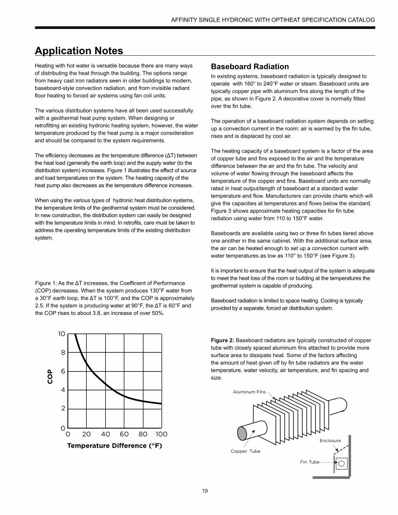
Figure 1: As the ΔT increases, the Coefficient of Performance (COP) decreases. When the system produces 130°F water from a 30°F earth loop, the ΔT is 100°F, and the COP is approximately 2.5. If the system is producing water at 90°F, the ΔT is 60°F and the COP rises to about 3.8, an increase of over 50%.
Figure 2: Baseboard radiators are typically constructed of copper tube with closely spaced aluminum fins attached to provide more surface area to dissipate heat. Some of the factors affecting the amount of heat given off by fin tube radiators are the water temperature, water velocity, air temperature, and fin spacing and size.
Baseboard RadiationIn existing systems, baseboard radiation is typically designed to operate with 160° to 240°F water or steam. Baseboard units are typically copper pipe with aluminum fins along the length of the pipe, as shown in Figure 2. A decorative cover is normally fitted over the fin tube.
The operation of a baseboard radiation system depends on setting up a convection current in the room: air is warmed by the fin tube, rises and is displaced by cool air.
The heating capacity of a baseboard system is a factor of the area of copper tube and fins exposed to the air and the temperature difference between the air and the fin tube. The velocity and volume of water flowing through the baseboard affects the temperature of the copper and fins. Baseboard units are normally rated in heat output/length of baseboard at a standard water temperature and flow. Manufacturers can provide charts which will give the capacities at temperatures and flows below the standard. Figure 3 shows approximate heating capacities for fin tube radiation using water from 110 to 150°F water.
Baseboards are available using two or three fin tubes tiered above one another in the same cabinet. With the additional surface area, the air can be heated enough to set up a convection current with water temperatures as low as 110° to 150°F (see Figure 3).
It is important to ensure that the heat output of the system is adequate to meet the heat loss of the room or building at the temperatures the geothermal system is capable of producing.
Baseboard radiation is limited to space heating. Cooling is typically provided by a separate, forced air distribution system.
Temperature Difference (°F)
0 20 40 60 80 100
CO
P
2
4
6
8
10
0
AFFINITY SINGLE HYDRONIC WITH OPTIHEAT SPECIFICATION CATALOG
20
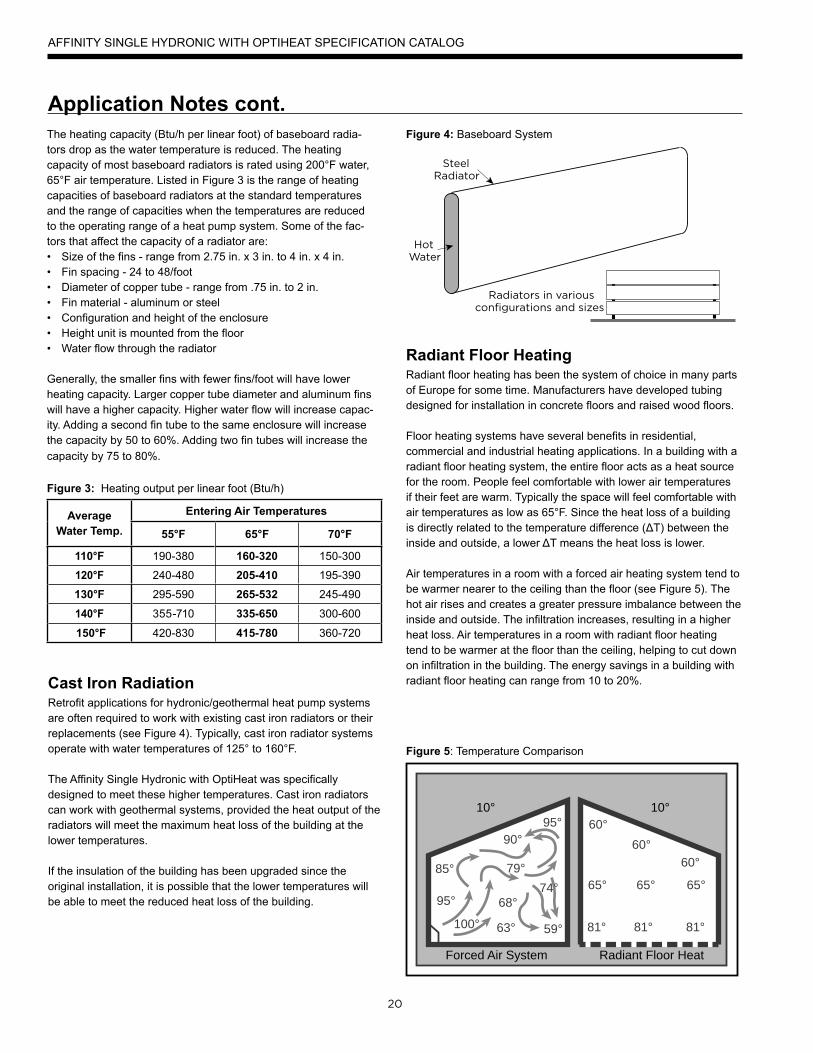
Application Notes cont.The heating capacity (Btu/h per linear foot) of baseboard radia-tors drop as the water temperature is reduced. The heating capacity of most baseboard radiators is rated using 200°F water, 65°F air temperature. Listed in Figure 3 is the range of heating capacities of baseboard radiators at the standard temperatures and the range of capacities when the temperatures are reduced to the operating range of a heat pump system. Some of the fac-tors that affect the capacity of a radiator are:• Size of the fins - range from 2.75 in. x 3 in. to 4 in. x 4 in.• Fin spacing - 24 to 48/foot• Diameter of copper tube - range from .75 in. to 2 in.• Fin material - aluminum or steel• Configuration and height of the enclosure• Height unit is mounted from the floor• Water flow through the radiator
Generally, the smaller fins with fewer fins/foot will have lower heating capacity. Larger copper tube diameter and aluminum fins will have a higher capacity. Higher water flow will increase capac-ity. Adding a second fin tube to the same enclosure will increase the capacity by 50 to 60%. Adding two fin tubes will increase the capacity by 75 to 80%.
Average Water Temp.
Entering Air Temperatures
55°F 65°F 70°F
110°F 190-380 160-320 150-300
120°F 240-480 205-410 195-390
130°F 295-590 265-532 245-490
140°F 355-710 335-650 300-600
150°F 420-830 415-780 360-720
Figure 3: Heating output per linear foot (Btu/h)
Radiant Floor HeatingRadiant floor heating has been the system of choice in many parts of Europe for some time. Manufacturers have developed tubing designed for installation in concrete floors and raised wood floors.
Floor heating systems have several benefits in residential, commercial and industrial heating applications. In a building with a radiant floor heating system, the entire floor acts as a heat source for the room. People feel comfortable with lower air temperatures if their feet are warm. Typically the space will feel comfortable with air temperatures as low as 65°F. Since the heat loss of a building is directly related to the temperature difference (ΔT) between the inside and outside, a lower ΔT means the heat loss is lower.
Air temperatures in a room with a forced air heating system tend to be warmer nearer to the ceiling than the floor (see Figure 5). The hot air rises and creates a greater pressure imbalance between the inside and outside. The infiltration increases, resulting in a higher heat loss. Air temperatures in a room with radiant floor heating tend to be warmer at the floor than the ceiling, helping to cut down on infiltration in the building. The energy savings in a building with radiant floor heating can range from 10 to 20%.
Figure 4: Baseboard System
Figure 5: Temperature Comparison
10° 10°
85°
95°
79°
68°
63° 81° 81° 81°
65° 65° 65°
60°60°
60°
Forced Air System Radiant Floor Heat
95°90°
74°
100° 59°
AFFINITY SINGLE HYDRONIC WITH OPTIHEAT SPECIFICATION CATALOG
Cast Iron Radiation Retrofit applications for hydronic/geothermal heat pump systems are often required to work with existing cast iron radiators or their replacements (see Figure 4). Typically, cast iron radiator systems operate with water temperatures of 125° to 160°F.
The Affinity Single Hydronic with OptiHeat was specifically designed to meet these higher temperatures. Cast iron radiators can work with geothermal systems, provided the heat output of the radiators will meet the maximum heat loss of the building at the lower temperatures.
If the insulation of the building has been upgraded since the original installation, it is possible that the lower temperatures will be able to meet the reduced heat loss of the building.
21
Application Notes cont.A floor heat system can be designed to heat a building with water temperatures as low as 90°F.
Figure 1 shows how a geothermal system operates more efficiently with a lower ΔT between the source and the load. With only a 60°F temperature difference, a hydronic geothermal heat pump will operate at COPs, about 20% higher than a forced air geothermal system in the same installation.
Some of the factors affecting the heating capacity of a floor heating system are as follows:• The type of finish flooring • The spacing of the pipe• The water flow through the pipe• The temperature of the supply water• The floor material (wood, concrete or poured Gypcrete™)• Insulation value under the floor• The piping layout
The spacing of the pipe in residential applications canvary from 4 in. to 12 in. If the spacing is too large, the temperature of the floor can vary noticeably. In industrial applications, variation in the floor temperature is not as important, and the spacing is related directly to the heat output required.
Radiant floor heating systems work well with geothermal heat pump systems. For efficient operation, the system must be designed with the lowest possible water temperatures.
There are some drawbacks with a radiant floor heating system. Air conditioning is only possible by adding a second system using forced air. This can add substantial cost to an installation where air conditioning is also needed. A separate air handling system is needed to clean the air or to introduce fresh air.
Industrial buildings, especially those with high ceilings and large overhead doors, have an advantage with a radiant floor heating system. Heat is stored in the concrete floor, and when a door is opened, the stored heat is immediately released to the space. The larger the ΔT between the air in the space and the floor, the quicker the floor releases its heat to the space.
Maintenance garages benefit from radiant floor heating systems. Cold vehicles brought into the garage are warmed from underneath. The snow melts off the vehicle and dries much more quickly than when heated from above.
Some pipe manufacturers include an oxygen diffusion barrier in the pipe to prevent oxygen diffusion through thepipe.
Good system design and careful installation, however, will eliminate virtually all of the problems encounteredwith air in the system. Like earth loop design, it is important to design the system to facilitate flushing the air initially and ensuring that the flows can be balanced properly.
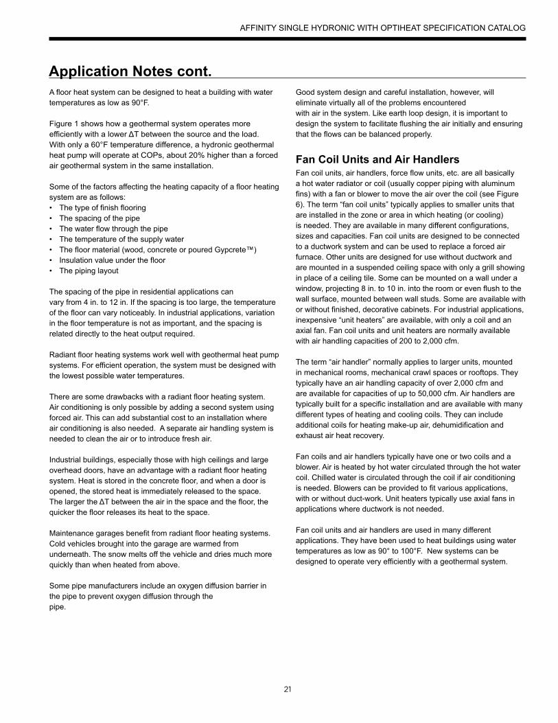
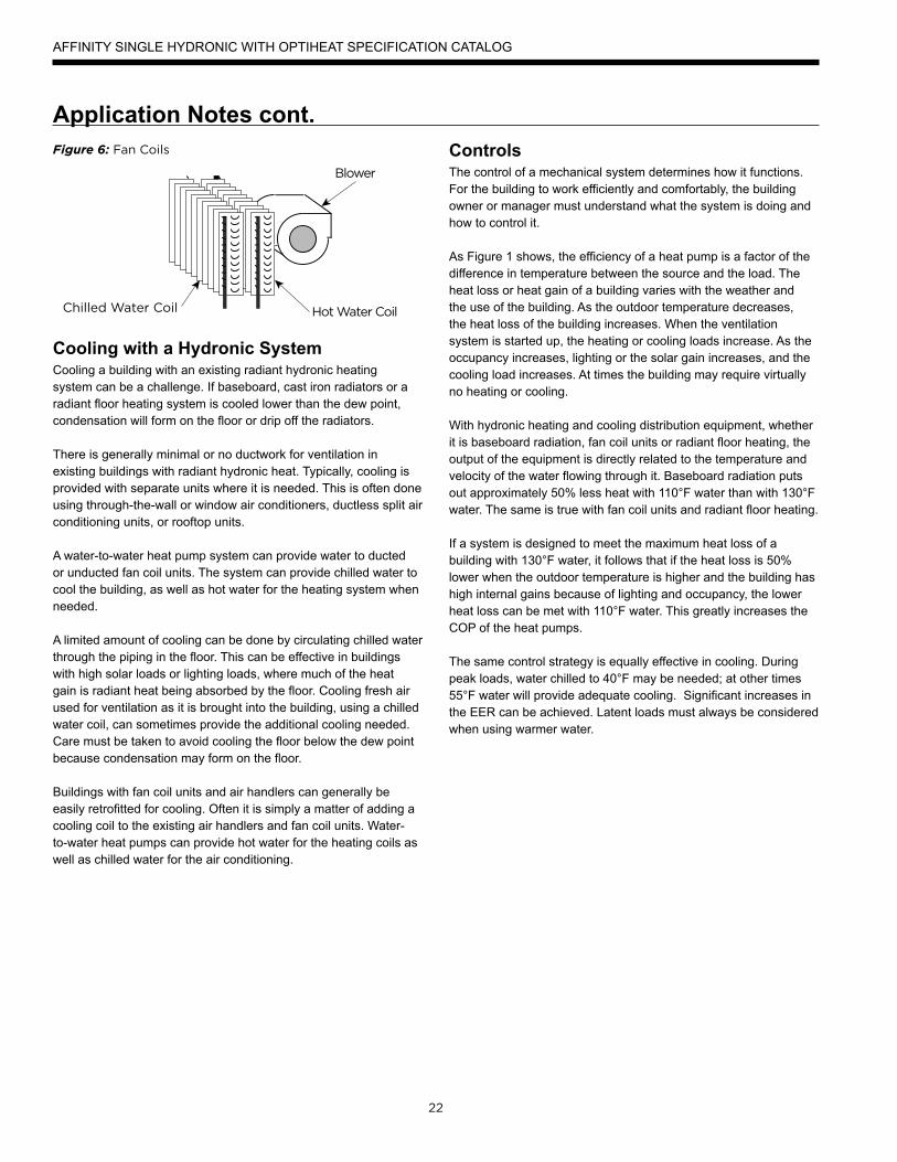
Fan Coil Units and Air HandlersFan coil units, air handlers, force flow units, etc. are all basically a hot water radiator or coil (usually copper piping with aluminum fins) with a fan or blower to move the air over the coil (see Figure 6). The term “fan coil units” typically applies to smaller units that are installed in the zone or area in which heating (or cooling) is needed. They are available in many different configurations, sizes and capacities. Fan coil units are designed to be connected to a ductwork system and can be used to replace a forced air furnace. Other units are designed for use without ductwork and are mounted in a suspended ceiling space with only a grill showing in place of a ceiling tile. Some can be mounted on a wall under a window, projecting 8 in. to 10 in. into the room or even flush to the wall surface, mounted between wall studs. Some are available with or without finished, decorative cabinets. For industrial applications, inexpensive “unit heaters” are available, with only a coil and an axial fan. Fan coil units and unit heaters are normally available with air handling capacities of 200 to 2,000 cfm.
The term “air handler” normally applies to larger units, mounted in mechanical rooms, mechanical crawl spaces or rooftops. They typically have an air handling capacity of over 2,000 cfm and are available for capacities of up to 50,000 cfm. Air handlers are typically built for a specific installation and are available with many different types of heating and cooling coils. They can include additional coils for heating make-up air, dehumidification and exhaust air heat recovery.
Fan coils and air handlers typically have one or two coils and a blower. Air is heated by hot water circulated through the hot water coil. Chilled water is circulated through the coil if air conditioning is needed. Blowers can be provided to fit various applications, with or without duct-work. Unit heaters typically use axial fans in applications where ductwork is not needed.
Fan coil units and air handlers are used in many different applications. They have been used to heat buildings using water temperatures as low as 90° to 100°F. New systems can be designed to operate very efficiently with a geothermal system.
AFFINITY SINGLE HYDRONIC WITH OPTIHEAT SPECIFICATION CATALOG
22
Application Notes cont.
Cooling with a Hydronic System Cooling a building with an existing radiant hydronic heating system can be a challenge. If baseboard, cast iron radiators or a radiant floor heating system is cooled lower than the dew point, condensation will form on the floor or drip off the radiators.
There is generally minimal or no ductwork for ventilation in existing buildings with radiant hydronic heat. Typically, cooling is provided with separate units where it is needed. This is often done using through-the-wall or window air conditioners, ductless split air conditioning units, or rooftop units.
A water-to-water heat pump system can provide water to ducted or unducted fan coil units. The system can provide chilled water to cool the building, as well as hot water for the heating system when needed.
A limited amount of cooling can be done by circulating chilled water through the piping in the floor. This can be effective in buildings with high solar loads or lighting loads, where much of the heat gain is radiant heat being absorbed by the floor. Cooling fresh air used for ventilation as it is brought into the building, using a chilled water coil, can sometimes provide the additional cooling needed. Care must be taken to avoid cooling the floor below the dew point because condensation may form on the floor.
Buildings with fan coil units and air handlers can generally be easily retrofitted for cooling. Often it is simply a matter of adding a cooling coil to the existing air handlers and fan coil units. Water-to-water heat pumps can provide hot water for the heating coils as well as chilled water for the air conditioning.
Figure 6: Fan Coils ControlsThe control of a mechanical system determines how it functions. For the building to work efficiently and comfortably, the building owner or manager must understand what the system is doing and how to control it.
As Figure 1 shows, the efficiency of a heat pump is a factor of the difference in temperature between the source and the load. The heat loss or heat gain of a building varies with the weather and the use of the building. As the outdoor temperature decreases, the heat loss of the building increases. When the ventilation system is started up, the heating or cooling loads increase. As the occupancy increases, lighting or the solar gain increases, and the cooling load increases. At times the building may require virtually no heating or cooling.
With hydronic heating and cooling distribution equipment, whether it is baseboard radiation, fan coil units or radiant floor heating, the output of the equipment is directly related to the temperature and velocity of the water flowing through it. Baseboard radiation puts out approximately 50% less heat with 110°F water than with 130°F water. The same is true with fan coil units and radiant floor heating.
If a system is designed to meet the maximum heat loss of a building with 130°F water, it follows that if the heat loss is 50% lower when the outdoor temperature is higher and the building has high internal gains because of lighting and occupancy, the lower heat loss can be met with 110°F water. This greatly increases the COP of the heat pumps.
The same control strategy is equally effective in cooling. During peak loads, water chilled to 40°F may be needed; at other times 55°F water will provide adequate cooling. Significant increases in the EER can be achieved. Latent loads must always be considered when using warmer water.
AFFINITY SINGLE HYDRONIC WITH OPTIHEAT SPECIFICATION CATALOG
23
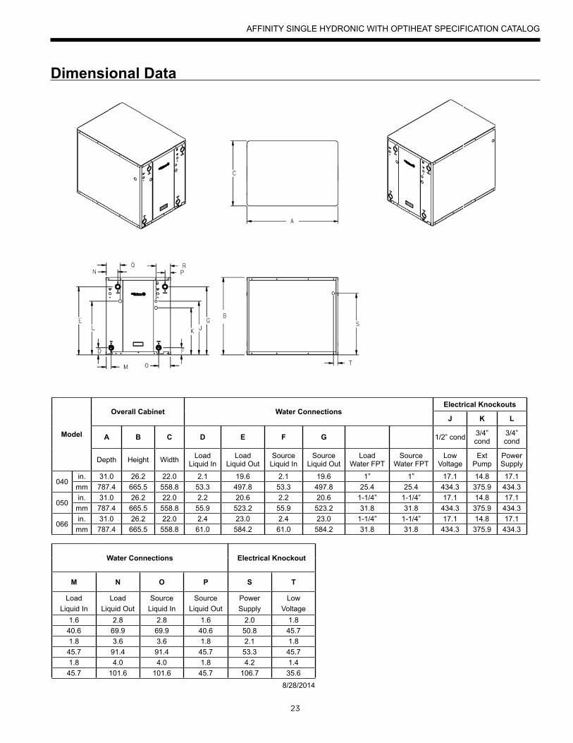
Dimensional Data
Model
Overall Cabinet Water ConnectionsElectrical Knockouts
J K L
A B C D E F G 1/2” cond 3/4” cond
3/4” cond
Depth Height Width Load Liquid In
Load Liquid Out
Source Liquid In
Source Liquid Out
Load Water FPT
Source Water FPT
Low Voltage
Ext Pump
Power Supply
040in. 31.0 26.2 22.0 2.1 19.6 2.1 19.6 1” 1” 17.1 14.8 17.1
mm 787.4 665.5 558.8 53.3 497.8 53.3 497.8 25.4 25.4 434.3 375.9 434.3
050in. 31.0 26.2 22.0 2.2 20.6 2.2 20.6 1-1/4” 1-1/4” 17.1 14.8 17.1
mm 787.4 665.5 558.8 55.9 523.2 55.9 523.2 31.8 31.8 434.3 375.9 434.3
066in. 31.0 26.2 22.0 2.4 23.0 2.4 23.0 1-1/4” 1-1/4” 17.1 14.8 17.1
mm 787.4 665.5 558.8 61.0 584.2 61.0 584.2 31.8 31.8 434.3 375.9 434.3
Water Connections Electrical Knockout
M N O P S T
Load Liquid In
Load Liquid Out
Source Liquid In
Source Liquid Out
Power Supply
Low Voltage
1.6 2.8 2.8 1.6 2.0 1.840.6 69.9 69.9 40.6 50.8 45.71.8 3.6 3.6 1.8 2.1 1.8
45.7 91.4 91.4 45.7 53.3 45.71.8 4.0 4.0 1.8 4.2 1.4
45.7 101.6 101.6 45.7 106.7 35.68/28/2014
AFFINITY SINGLE HYDRONIC WITH OPTIHEAT SPECIFICATION CATALOG
24
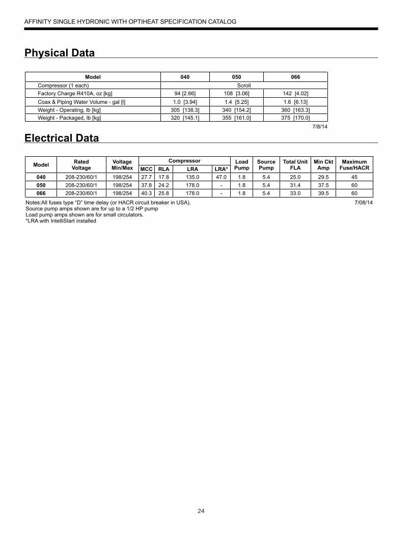
Electrical Data
Physical Data
Model RatedVoltage
VoltageMin/Max
Compressor LoadPump
SourcePump
Total UnitFLA
Min CktAmp
MaximumFuse/HACRMCC RLA LRA LRA*
040 208-230/60/1 198/254 27.7 17.8 135.0 47.0 1.8 5.4 25.0 29.5 45050 208-230/60/1 198/254 37.8 24.2 178.0 - 1.8 5.4 31.4 37.5 60066 208-230/60/1 198/254 40.3 25.8 178.0 - 1.8 5.4 33.0 39.5 60
Notes:All fuses type “D” time delay (or HACR circuit breaker in USA). 7/08/14Source pump amps shown are for up to a 1/2 HP pumpLoad pump amps shown are for small circulators.*LRA with IntelliStart installed
Model 040 050 066Compressor (1 each) ScrollFactory Charge R410A, oz [kg] 94 [2.66] 108 [3.06] 142 [4.02]Coax & Piping Water Volume - gal [l] 1.0 [3.94] 1.4 [5.25] 1.6 [6.13]Weight - Operating, lb [kg] 305 [138.3] 340 [154.2] 360 [163.3]Weight - Packaged, lb [kg] 320 [145.1] 355 [161.0] 375 [170.0]
7/8/14
AFFINITY SINGLE HYDRONIC WITH OPTIHEAT SPECIFICATION CATALOG
25
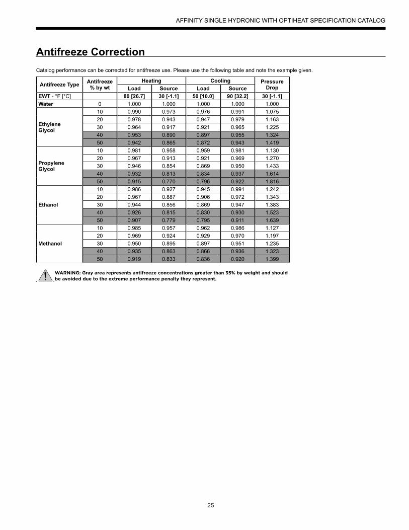
Catalog performance can be corrected for antifreeze use. Please use the following table and note the example given.
Antifreeze Type Antifreeze % by wt
Heating Cooling Pressure DropLoad Source Load Source
EWT - °F [°C] 80 [26.7] 30 [-1.1] 50 [10.0] 90 [32.2] 30 [-1.1]Water 0 1.000 1.000 1.000 1.000 1.000
Ethylene Glycol
10 0.990 0.973 0.976 0.991 1.07520 0.978 0.943 0.947 0.979 1.16330 0.964 0.917 0.921 0.965 1.22540 0.953 0.890 0.897 0.955 1.32450 0.942 0.865 0.872 0.943 1.419
Propylene Glycol
10 0.981 0.958 0.959 0.981 1.13020 0.967 0.913 0.921 0.969 1.27030 0.946 0.854 0.869 0.950 1.43340 0.932 0.813 0.834 0.937 1.61450 0.915 0.770 0.796 0.922 1.816
Ethanol
10 0.986 0.927 0.945 0.991 1.24220 0.967 0.887 0.906 0.972 1.34330 0.944 0.856 0.869 0.947 1.38340 0.926 0.815 0.830 0.930 1.52350 0.907 0.779 0.795 0.911 1.639
Methanol
10 0.985 0.957 0.962 0.986 1.12720 0.969 0.924 0.929 0.970 1.19730 0.950 0.895 0.897 0.951 1.23540 0.935 0.863 0.866 0.936 1.32350 0.919 0.833 0.836 0.920 1.399
WARNING: Gray area represents antifreeze concentrations greater than 35% by weight and should be avoided due to the extreme performance penalty they represent.
Antifreeze Correction
AFFINITY SINGLE HYDRONIC WITH OPTIHEAT SPECIFICATION CATALOG
26
Water Pressure Drop
110˚F
30˚F
110˚F
30˚F
Model 040
Model 050
AFFINITY SINGLE HYDRONIC WITH OPTIHEAT SPECIFICATION CATALOG
27
Water Pressure Drop cont.
Pressure Drop
110˚F
30˚F
Model 066
Model GPMPressure Drop (psi)
30°F 50°F 70°F 90°F 110°F 130°F 150°F
040
5.0 0.9 0.6 0.6 0.5 0.5 0.4 0.3
7.5 2.3 2.1 2.0 1.9 1.8 1.6 1.5
10.0 3.7 3.5 3.3 3.2 3.0 2.8 2.7
12.5 5.0 4.7 4.4 4.2 4.1 3.9 3.7
050
8.0 1.7 1.4 1.4 1.3 1.3 1.2 1.1
11.5 3.6 3.4 3.2 3.0 2.8 2.6 2.5
15.0 5.6 5.4 5.0 4.6 4.4 4.3 4.1
18.5 8.3 8.1 7.6 7.2 6.8 6.6 6.4
066
10.0 3.2 3.0 2.8 2.7 2.5 2.4 2.3
14.5 5.5 5.3 5.1 4.9 4.7 4.6 4.5
19.0 7.9 7.6 7.3 7.1 6.8 6.6 6.5
23.5 11.5 11.3 11.0 10.8 10.3 10.1 9.9
7/8/14
AFFINITY SINGLE HYDRONIC WITH OPTIHEAT SPECIFICATION CATALOG

28
Heating Operating Envelope
Cooling Operating Envelope
New
65
75
85
95
105
115
125
135
145
155
165
20 30 40 50 60 70 80 90 100
Load
Lea
ving
Tem
pera
ture
, o F
Source Entering Temperature, oF
Safe Operating Range
Caution: Sensitive Operating Range
Operation Not Allowed
AFFINITY SINGLE HYDRONIC WITH OPTIHEAT SPECIFICATION CATALOG

29
Reference Calculations
Legend and Notes
Heating Calculations: LWT = EWT - HE GPM x C*
Cooling Calculations: LWT = EWT + HR
GPM x C*
HE = C* x GPM x (EWT - LWT) HR = C* x GPM x (LWT - EWT)
NOTE: * C = 500 for pure water, 485 for brine.
Abbreviations and DefinitionsELT = entering load fluid temperature to heat pump kW = kilowatts
SWPD = source coax water pressure drop EST = entering source fluid temperature to heat pump
LLT = leaving load fluid temperature from heat pump HE = heat extracted in MBTUH
PSI = pressure drop in pounds per square inch LST = leaving source fluid temperature from heat pump
LGPM = load flow in gallons per minute HC = total heating capacity in MBTUH
FT HD = pressure drop in feet of head COP = coefficient of performance, heating [HC/kW x 3.413]
LWPD = load coax water pressure drop EER = energy efficiency ratio, cooling
LWT = leaving water temperature TC = total cooling capacity in MBTUH
EWT = entering water temperature HR = heat rejected in MBTUH
Brine = water with a freeze inhibiting solution
Notes to Performance Data TablesThe following notes apply to all performance data tables:• Three flow rates are shown for each unit. The lowest flow rate shown is used for geothermal open loop/well water systems with a minimum of 50°F EST. The middle flow rate shown is the minimum geothermal closed loop flow rate. The highest flow rate shown is optimum for geothermal closed loop systems and the suggested flow rate for boiler/ tower applications. • Entering water temperatures below 40°F assumes 15% antifreeze solution. • Interpolation between ELT, EST, and GPM data is permissible. • Operation in the gray areas is not recommended.
AFFINITY SINGLE HYDRONIC WITH OPTIHEAT SPECIFICATION CATALOG

30
Performance Data040-Heating
Source Load Flow - 5 GPM Load Flow - 8 GPM Load Flow - 10 GPMEST°F
FlowGPM
ELT°F
LLT°F
HCMBTUH
PowerkW
HEMBTUH
COPLST°F
LLT°F
HCMBTUH
PowerkW
HEMBTUH
COPLST°F
LLT°F
HCMBTUH
PowerkW
HEMBTUH
COPLST°F
30
5
60 72.7 31.7 1.8 25.4 5.0 19.5 68.0 32.0 1.8 25.8 5.2 19.3 66.4 32.2 1.8 26.2 5.4 19.280 93.0 32.5 2.3 24.6 4.1 19.9 88.2 32.8 2.3 25.1 4.2 19.7 86.6 33.0 2.2 25.4 4.3 19.5
100 113.3 33.4 3.0 23.3 3.3 20.4 108.4 33.7 2.9 23.9 3.4 20.2 106.8 33.9 2.8 24.3 3.5 20.0130 144.0 35.0 3.9 21.8 2.6 21.0 138.8 35.3 3.8 22.5 2.7 20.7 137.1 35.5 3.7 22.9 2.8 20.5140 Operation not recommended 148.9 35.5 4.2 21.2 2.5 21.3 147.1 35.7 4.1 21.7 2.5 21.1
8
60 73.0 32.4 1.9 26.1 5.1 23.3 68.2 32.7 1.8 26.5 5.3 23.2 66.6 32.9 1.8 26.9 5.4 23.180 93.3 33.2 2.5 24.7 3.9 23.6 88.4 33.5 2.4 25.3 4.1 23.5 86.7 33.7 2.4 25.6 4.2 23.4
100 113.6 33.9 3.1 23.4 3.2 24.0 108.6 34.3 3.0 24.0 3.3 23.8 106.9 34.5 3.0 24.4 3.4 23.7130 144.0 35.1 4.0 21.3 2.5 24.5 138.9 35.4 3.9 22.0 2.6 24.3 137.1 35.6 3.8 22.5 2.7 24.2140 Operation not recommended 149.0 35.8 4.2 21.4 2.5 24.5 147.2 36.0 4.1 21.9 2.6 24.4
10
60 73.2 32.9 1.9 26.5 5.2 24.5 68.3 33.2 1.8 27.0 5.4 24.4 66.7 33.4 1.8 27.3 5.5 24.480 93.5 33.8 2.4 25.7 4.2 24.7 88.5 34.1 2.3 26.3 4.4 24.6 86.9 34.3 2.3 26.6 4.5 24.5
100 113.8 34.5 3.0 24.3 3.4 25.0 108.7 34.8 2.9 24.9 3.5 24.9 107.0 35.0 2.8 25.3 3.6 24.8130 144.2 35.5 3.9 22.1 2.7 25.4 138.9 35.8 3.8 22.8 2.8 25.3 137.2 36.0 3.7 23.3 2.8 25.2140 Operation not recommended 149.0 36.0 4.2 21.5 2.5 25.6 147.2 36.2 4.2 22.0 2.6 25.5
50
5
60 74.8 37.0 1.8 30.9 6.1 37.3 69.3 37.3 1.7 31.4 6.3 37.1 67.5 37.5 1.7 31.7 6.5 36.980 95.2 38.1 2.3 30.4 4.9 37.5 89.6 38.4 2.2 30.9 5.1 37.2 87.7 38.7 2.2 31.3 5.3 37.1
100 115.6 39.0 3.0 29.0 3.9 38.1 109.8 39.4 2.9 29.6 4.0 37.8 107.9 39.6 2.8 30.0 4.1 37.6130 146.4 41.0 3.8 28.1 3.2 38.4 140.3 41.3 3.7 28.9 3.3 38.1 138.3 41.6 3.6 29.3 3.4 37.9140 Operation not recommended Operation not recommended 148.4 42.0 4.2 27.8 3.0 38.5
8
60 75.1 37.8 1.8 31.7 6.2 41.8 69.5 38.2 1.7 32.2 6.4 41.7 67.7 38.4 1.7 32.6 6.6 41.680 95.5 38.8 2.4 30.4 4.6 42.2 89.8 39.2 2.4 31.0 4.8 42.0 87.9 39.4 2.3 31.4 5.0 41.9
100 115.9 39.8 3.1 29.2 3.8 42.5 110.0 40.1 3.0 29.9 3.9 42.3 108.1 40.4 3.0 30.3 4.0 42.2130 146.5 41.2 4.1 27.3 3.0 43.0 140.4 41.6 4.0 28.1 3.1 42.8 138.4 41.9 3.9 28.6 3.2 42.6140 Operation not recommended Operation not recommended 148.5 42.4 4.2 28.1 3.0 42.8
10
60 75.4 38.4 1.8 32.2 6.2 43.4 69.7 38.7 1.8 32.8 6.5 43.2 67.8 39.0 1.7 33.1 6.6 43.280 95.8 39.5 2.3 31.7 5.1 43.5 90.0 39.9 2.2 32.3 5.3 43.3 88.0 40.1 2.2 32.7 5.4 43.3
100 116.1 40.3 3.0 30.2 4.0 43.8 110.2 40.7 2.9 30.9 4.1 43.6 108.2 40.9 2.8 31.3 4.2 43.5130 146.6 41.5 3.8 28.6 3.2 44.1 140.5 41.9 3.7 29.3 3.3 44.0 138.4 42.1 3.6 29.8 3.4 43.9140 Operation not recommended Operation not recommended 148.5 42.6 4.2 28.3 3.0 44.2
70
5
60 77.1 42.8 1.8 36.8 7.1 54.8 70.8 43.2 1.7 37.3 7.4 54.6 68.7 43.4 1.7 37.7 7.6 54.480 99.0 47.4 3.0 37.2 4.6 54.7 91.3 45.2 2.6 36.4 5.1 55.0 88.8 43.8 2.3 35.9 5.6 55.2
100 120.8 52.0 4.2 37.6 3.6 54.5 111.9 47.6 3.4 36.0 4.1 55.2 108.9 44.7 2.9 34.9 4.5 55.6130 153.5 58.9 6.1 38.2 2.8 54.3 142.8 51.0 4.8 34.8 3.1 55.7 139.2 45.8 3.9 32.5 3.4 56.6140 Operation not recommended Operation not recommended 149.2 45.9 4.2 31.6 3.2 57.0
8
60 78.0 44.9 1.8 38.9 7.5 60.0 71.2 44.6 1.7 38.8 7.6 60.0 68.9 44.4 1.7 38.7 7.8 60.080 99.9 49.7 3.0 39.5 4.9 59.8 91.7 46.8 2.6 38.0 5.3 60.2 89.0 44.9 2.3 37.0 5.7 60.5
100 121.8 54.6 4.2 40.1 3.8 59.7 112.3 49.0 3.5 37.2 4.1 60.4 109.1 45.4 3.0 35.3 4.5 60.9130 154.7 61.8 6.1 41.0 3.0 59.4 143.1 52.4 4.8 36.0 3.2 60.7 139.2 46.1 3.9 32.7 3.4 61.6140 Operation not recommended Operation not recommended 149.3 46.3 4.2 31.8 3.2 61.8
10
60 78.5 46.3 1.8 40.3 7.7 61.7 71.4 45.6 1.7 39.7 7.8 61.8 69.0 45.1 1.7 39.4 7.9 61.980 100.5 51.3 3.0 41.0 5.0 61.5 91.9 47.8 2.6 38.9 5.4 62.0 89.1 45.5 2.3 37.5 5.7 62.3
100 122.5 56.3 4.3 41.8 3.9 61.4 112.6 50.2 3.4 38.5 4.3 62.1 109.2 46.2 2.9 36.3 4.7 62.5130 155.5 63.8 6.1 42.9 3.0 61.2 143.3 53.3 4.8 36.9 3.3 62.4 139.3 46.3 3.9 33.0 3.5 63.2140 Operation not recommended Operation not recommended 149.3 46.5 4.2 32.0 3.2 63.4
90
5
60 81.1 52.7 1.7 47.0 9.1 70.6 73.3 53.2 1.7 47.6 9.4 70.4 70.7 53.5 1.6 48.0 9.6 70.280 101.3 53.3 2.3 45.5 6.8 71.2 93.4 53.8 2.2 46.2 7.0 71.0 90.8 54.1 2.2 46.6 7.2 70.8
100 121.7 54.3 2.9 44.6 5.6 71.6 113.7 54.8 2.8 45.3 5.7 71.3 111.0 55.2 2.8 45.7 5.8 71.1130 151.7 54.3 3.8 41.4 4.2 72.9 143.7 54.8 3.7 42.1 4.3 72.6 141.0 55.1 3.7 42.6 4.4 72.4140 Operation not recommended
z8
60 81.6 54.0 1.7 48.2 9.3 77.6 73.6 54.4 1.7 48.8 9.6 77.4 71.0 54.8 1.6 49.2 9.8 77.380 105.1 62.8 3.5 50.7 5.2 76.9 94.5 57.9 2.8 48.4 6.1 77.5 90.9 54.7 2.3 46.8 7.0 77.9
100 128.6 71.6 5.4 53.2 3.9 76.3 115.3 61.4 3.9 47.9 4.6 77.6 110.9 54.5 3.0 44.4 5.4 78.5130 163.9 84.8 8.2 57.0 3.0 75.3 146.6 66.6 5.6 47.3 3.5 77.8 140.9 54.4 4.0 40.9 4.0 79.5140 Operation not recommended
10
60 81.9 54.8 1.7 48.9 9.4 79.9 73.8 55.3 1.7 49.6 9.7 79.8 71.1 55.6 1.7 50.0 9.9 79.780 102.1 55.4 2.3 47.5 7.0 80.2 94.0 55.9 2.3 48.1 7.2 80.1 91.2 56.2 2.2 48.6 7.4 80.0
100 122.5 56.1 2.9 46.3 5.7 80.4 114.2 56.7 2.8 47.0 5.9 80.3 111.4 57.0 2.8 47.5 6.0 80.2130 152.0 55.0 3.8 42.0 4.2 81.3 143.9 55.5 3.7 42.7 4.4 81.2 141.2 55.8 3.7 43.2 4.4 81.1140 Operation not recommended
4/14/15
AFFINITY SINGLE HYDRONIC WITH OPTIHEAT SPECIFICATION CATALOG
31
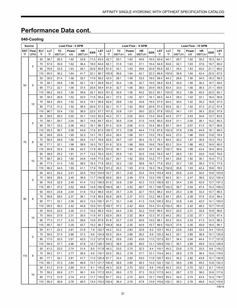
Performance Data cont.040-Cooling
Source Load Flow - 5 GPM Load Flow - 8 GPM Load Flow - 10 GPM
ESTºF
FlowGPM
ELTºF
LLTºF
TCMBTUH
PowerkW
HRMBTUH EER LST
ºFLLTºF
TCMBTUH
PowerkW
HRMBTUH EER LST
ºFLLTºF
TCMBTUH
PowerkW
HRMBTUH EER LST
ºF
50
5
50 38.7 28.3 1.62 33.8 17.5 63.5 42.7 29.1 1.62 34.6 18.0 63.9 44.1 29.7 1.62 35.2 18.3 64.1
70 57.6 30.9 1.62 36.4 19.0 64.6 62.1 31.6 1.63 37.1 19.4 64.9 63.6 32.1 1.63 37.6 19.7 65.0
90 76.6 33.5 1.63 39.1 20.6 65.6 81.5 34.1 1.63 39.6 20.9 65.9 83.1 34.4 1.63 40.0 21.1 66.0
110 95.5 36.2 1.64 41.7 22.1 66.7 100.9 36.6 1.64 42.1 22.3 66.9 102.6 36.8 1.64 42.4 22.5 67.0
8
50 39.0 27.4 1.56 32.7 17.6 58.2 43.0 28.1 1.56 33.5 18.0 58.4 44.3 28.6 1.56 34.0 18.3 58.5
70 58.1 29.8 1.56 35.1 19.1 58.8 62.4 30.4 1.56 35.7 19.5 58.9 63.8 30.8 1.56 36.2 19.7 59.0
90 77.2 32.1 1.56 37.4 20.6 59.4 81.8 32.7 1.56 38.0 20.9 59.5 83.4 33.0 1.56 38.3 21.1 59.6
110 96.2 34.5 1.56 39.8 22.1 60.0 101.3 34.9 1.56 40.2 22.3 60.1 103.0 35.2 1.56 40.5 22.5 60.1
10
50 39.3 26.8 1.52 32.0 17.6 56.4 43.1 27.5 1.52 32.7 18.1 56.5 44.4 28.0 1.52 33.1 18.4 56.6
70 58.4 29.0 1.52 34.2 19.1 56.8 62.6 29.6 1.52 34.8 19.5 57.0 64.0 30.0 1.52 35.2 19.8 57.0
90 77.5 31.2 1.52 36.4 20.6 57.3 82.1 31.7 1.52 36.9 20.9 57.4 83.6 32.1 1.52 37.2 21.2 57.4
110 96.7 33.4 1.52 38.5 22.0 57.7 101.5 33.8 1.51 39.0 22.3 57.8 103.2 34.1 1.51 39.3 22.6 57.9
70
5
50 39.5 26.3 2.02 33.1 13.0 83.3 43.2 27.1 2.02 34.0 13.4 83.6 44.5 27.7 2.03 34.6 13.7 83.9
70 58.1 29.7 2.04 36.7 14.6 84.7 62.4 30.5 2.04 37.5 14.9 85.0 63.8 31.1 2.05 38.1 15.2 85.2
90 76.7 33.2 2.06 40.2 16.1 86.1 81.5 33.9 2.06 41.0 16.4 86.4 83.1 34.4 2.07 41.5 16.7 86.6
110 95.3 36.7 2.08 43.8 17.6 87.5 100.7 37.3 2.08 44.4 17.9 87.8 102.4 37.8 2.09 44.9 18.1 88.0
8
50 39.8 25.6 1.95 32.3 13.1 78.1 43.4 26.4 1.96 33.1 13.5 78.3 44.6 27.0 1.96 33.6 13.8 78.4
70 58.5 28.9 1.96 35.6 14.7 78.9 62.6 29.7 1.97 36.4 15.1 79.1 64.0 30.2 1.97 36.9 15.3 79.2
90 77.1 32.1 1.98 38.9 16.3 79.7 81.8 32.9 1.98 39.6 16.6 79.9 83.3 33.4 1.98 40.2 16.9 80.0
110 95.8 35.4 1.99 42.2 17.8 80.5 101.0 36.1 1.99 42.9 18.1 80.7 102.7 36.6 1.99 43.4 18.4 80.9
10
50 39.9 25.2 1.91 31.7 13.2 76.3 43.5 25.9 1.91 32.5 13.6 76.5 44.7 26.5 1.91 33.0 13.8 76.6
70 58.7 28.3 1.92 34.8 14.8 77.0 62.7 29.1 1.92 35.6 15.2 77.1 64.1 29.6 1.92 36.1 15.4 77.2
90 77.4 31.4 1.92 38.0 16.3 77.6 82.0 32.2 1.92 38.8 16.7 77.8 83.5 32.7 1.92 39.3 17.0 77.9
110 96.2 34.5 1.93 41.1 17.9 78.2 101.2 35.3 1.93 41.9 18.3 78.4 102.8 35.8 1.93 42.4 18.6 78.5
90
5
50 40.3 24.2 2.41 32.5 10.0 103.0 43.7 25.1 2.42 33.4 10.4 103.4 44.8 25.8 2.43 34.0 10.6 103.6
70 58.6 28.6 2.45 36.9 11.7 104.8 62.6 29.5 2.46 37.9 12.0 105.1 64.0 30.1 2.47 38.5 12.2 105.4
90 76.9 32.9 2.49 41.4 13.2 106.5 81.6 33.8 2.50 42.3 13.5 106.9 83.1 34.4 2.50 42.9 13.7 107.2
110 95.1 37.2 2.52 45.8 14.8 108.3 100.5 38.1 2.53 46.7 15.1 108.7 102.3 38.7 2.54 47.4 15.3 109.0
8
50 40.5 23.8 2.34 31.8 10.2 98.0 43.8 24.7 2.35 32.7 10.5 98.2 44.9 25.3 2.36 33.3 10.7 98.3
70 58.8 28.0 2.37 36.1 11.8 99.0 62.8 28.9 2.37 37.0 12.2 99.3 64.1 29.5 2.38 37.6 12.4 99.4
90 77.1 32.1 2.39 40.3 13.4 100.1 81.7 33.1 2.40 41.3 13.8 100.3 83.2 33.8 2.40 42.0 14.1 100.5
110 95.5 36.3 2.42 44.6 15.0 101.1 100.7 37.3 2.42 45.6 15.4 101.4 102.4 38.0 2.42 46.3 15.7 101.6
10
50 40.6 23.5 2.30 31.3 10.2 96.3 43.9 24.4 2.30 32.2 10.6 96.4 45.0 25.0 2.31 32.8 10.8 96.6
70 59.0 27.6 2.31 35.5 11.9 97.1 62.9 28.5 2.32 36.4 12.3 97.3 64.2 29.2 2.32 37.1 12.6 97.4
90 77.3 31.7 2.33 39.6 13.6 97.9 81.8 32.7 2.33 40.6 14.0 98.1 83.3 33.4 2.33 41.3 14.3 98.3
110 95.7 35.7 2.35 43.7 15.2 98.7 100.8 36.8 2.35 44.8 15.7 99.0 102.5 37.6 2.35 45.6 16.0 99.1
110
5
50 41.1 22.2 2.81 31.8 7.9 122.7 44.2 23.2 2.83 32.8 8.2 123.1 45.2 23.8 2.83 33.5 8.4 123.4
70 59.0 27.4 2.86 37.2 9.6 124.9 62.9 28.4 2.88 38.2 9.9 125.3 64.2 29.1 2.89 38.9 10.1 125.6
90 77.0 32.5 2.91 42.5 11.2 127.0 81.6 33.6 2.93 43.6 11.5 127.5 83.1 34.4 2.94 44.4 11.7 127.8
110 94.9 37.7 2.96 47.8 12.7 129.1 100.3 38.9 2.98 49.0 13.1 129.6 102.1 39.7 2.99 49.9 13.3 129.9
8
50 41.2 22.0 2.74 31.4 8.0 117.8 44.3 23.0 2.75 32.3 8.4 118.1 45.3 23.6 2.75 33.0 8.6 118.2
70 59.2 27.1 2.77 36.5 9.8 119.1 63.0 28.2 2.78 37.7 10.1 119.4 64.2 28.9 2.79 38.4 10.4 119.6
90 77.1 32.1 2.81 41.7 11.5 120.4 81.7 33.4 2.82 43.0 11.9 120.7 83.2 34.2 2.82 43.8 12.1 120.9
110 95.1 37.2 2.84 46.9 13.1 121.7 100.4 38.6 2.85 48.3 13.5 122.1 102.1 39.5 2.85 49.2 13.8 122.3
10
50 41.3 21.9 2.69 31.0 8.1 116.2 44.3 22.8 2.70 32.0 8.5 116.4 45.3 23.5 2.70 32.7 8.7 116.5
70 59.2 26.9 2.71 36.1 9.9 117.2 63.0 28.0 2.72 37.3 10.3 117.5 64.3 28.7 2.72 38.0 10.6 117.6
90 77.2 31.9 2.74 41.2 11.7 118.2 81.7 33.2 2.74 42.5 12.1 118.5 83.2 34.0 2.74 43.4 12.4 118.7
110 95.2 36.9 2.76 46.3 13.4 119.3 100.4 38.4 2.76 47.8 13.9 119.6 102.1 39.3 2.76 48.8 14.2 119.8
7/8/14
AFFINITY SINGLE HYDRONIC WITH OPTIHEAT SPECIFICATION CATALOG
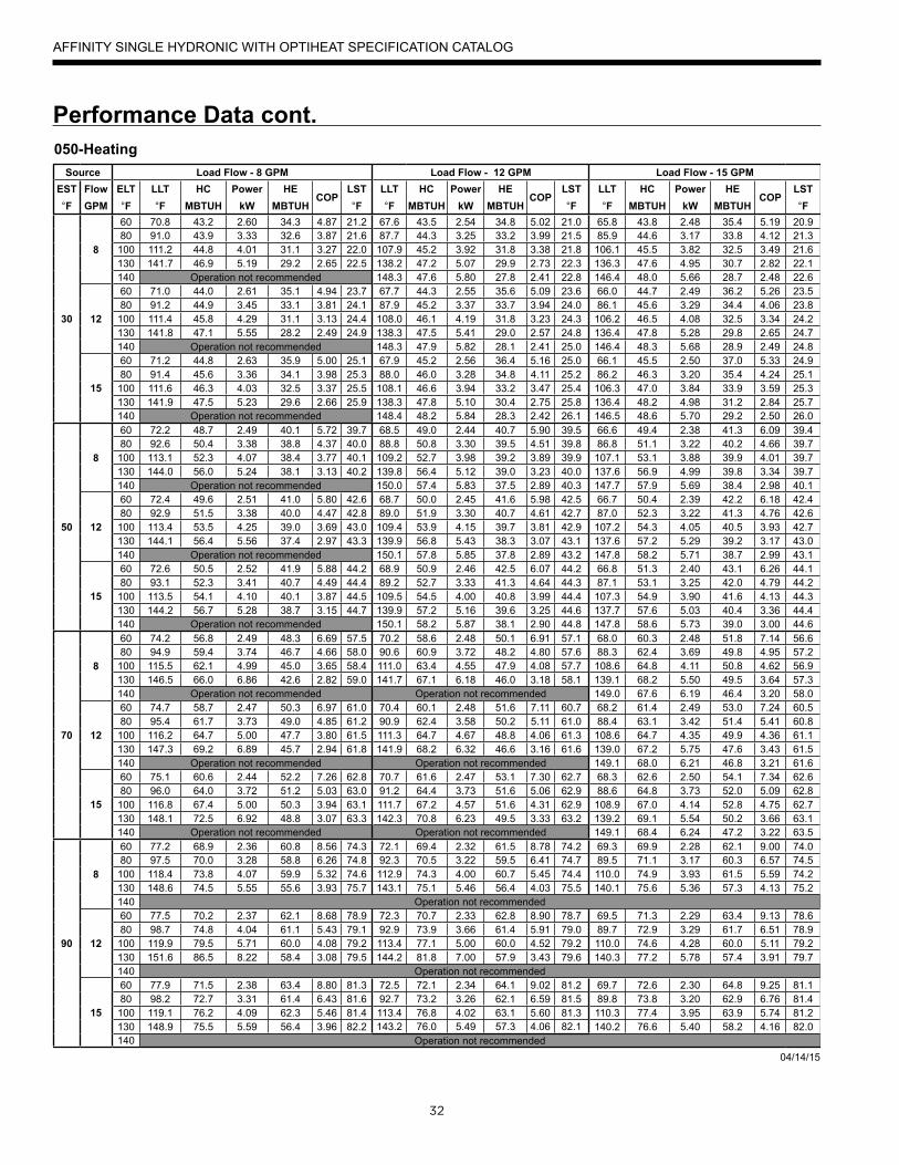
32
Performance Data cont.050-Heating
Source Load Flow - 8 GPM Load Flow - 12 GPM Load Flow - 15 GPMEST°F
FlowGPM
ELT°F
LLT°F
HCMBTUH
PowerkW
HEMBTUH
COPLST°F
LLT°F
HCMBTUH
PowerkW
HEMBTUH
COPLST°F
LLT°F
HCMBTUH
PowerkW
HEMBTUH
COPLST°F
30
8
60 70.8 43.2 2.60 34.3 4.87 21.2 67.6 43.5 2.54 34.8 5.02 21.0 65.8 43.8 2.48 35.4 5.19 20.980 91.0 43.9 3.33 32.6 3.87 21.6 87.7 44.3 3.25 33.2 3.99 21.5 85.9 44.6 3.17 33.8 4.12 21.3
100 111.2 44.8 4.01 31.1 3.27 22.0 107.9 45.2 3.92 31.8 3.38 21.8 106.1 45.5 3.82 32.5 3.49 21.6130 141.7 46.9 5.19 29.2 2.65 22.5 138.2 47.2 5.07 29.9 2.73 22.3 136.3 47.6 4.95 30.7 2.82 22.1140 Operation not recommended 148.3 47.6 5.80 27.8 2.41 22.8 146.4 48.0 5.66 28.7 2.48 22.6
12
60 71.0 44.0 2.61 35.1 4.94 23.7 67.7 44.3 2.55 35.6 5.09 23.6 66.0 44.7 2.49 36.2 5.26 23.580 91.2 44.9 3.45 33.1 3.81 24.1 87.9 45.2 3.37 33.7 3.94 24.0 86.1 45.6 3.29 34.4 4.06 23.8
100 111.4 45.8 4.29 31.1 3.13 24.4 108.0 46.1 4.19 31.8 3.23 24.3 106.2 46.5 4.08 32.5 3.34 24.2130 141.8 47.1 5.55 28.2 2.49 24.9 138.3 47.5 5.41 29.0 2.57 24.8 136.4 47.8 5.28 29.8 2.65 24.7140 Operation not recommended 148.3 47.9 5.82 28.1 2.41 25.0 146.4 48.3 5.68 28.9 2.49 24.8
15
60 71.2 44.8 2.63 35.9 5.00 25.1 67.9 45.2 2.56 36.4 5.16 25.0 66.1 45.5 2.50 37.0 5.33 24.980 91.4 45.6 3.36 34.1 3.98 25.3 88.0 46.0 3.28 34.8 4.11 25.2 86.2 46.3 3.20 35.4 4.24 25.1
100 111.6 46.3 4.03 32.5 3.37 25.5 108.1 46.6 3.94 33.2 3.47 25.4 106.3 47.0 3.84 33.9 3.59 25.3130 141.9 47.5 5.23 29.6 2.66 25.9 138.3 47.8 5.10 30.4 2.75 25.8 136.4 48.2 4.98 31.2 2.84 25.7140 Operation not recommended 148.4 48.2 5.84 28.3 2.42 26.1 146.5 48.6 5.70 29.2 2.50 26.0
50
8
60 72.2 48.7 2.49 40.1 5.72 39.7 68.5 49.0 2.44 40.7 5.90 39.5 66.6 49.4 2.38 41.3 6.09 39.480 92.6 50.4 3.38 38.8 4.37 40.0 88.8 50.8 3.30 39.5 4.51 39.8 86.8 51.1 3.22 40.2 4.66 39.7
100 113.1 52.3 4.07 38.4 3.77 40.1 109.2 52.7 3.98 39.2 3.89 39.9 107.1 53.1 3.88 39.9 4.01 39.7130 144.0 56.0 5.24 38.1 3.13 40.2 139.8 56.4 5.12 39.0 3.23 40.0 137.6 56.9 4.99 39.8 3.34 39.7140 Operation not recommended 150.0 57.4 5.83 37.5 2.89 40.3 147.7 57.9 5.69 38.4 2.98 40.1
12
60 72.4 49.6 2.51 41.0 5.80 42.6 68.7 50.0 2.45 41.6 5.98 42.5 66.7 50.4 2.39 42.2 6.18 42.480 92.9 51.5 3.38 40.0 4.47 42.8 89.0 51.9 3.30 40.7 4.61 42.7 87.0 52.3 3.22 41.3 4.76 42.6
100 113.4 53.5 4.25 39.0 3.69 43.0 109.4 53.9 4.15 39.7 3.81 42.9 107.2 54.3 4.05 40.5 3.93 42.7130 144.1 56.4 5.56 37.4 2.97 43.3 139.9 56.8 5.43 38.3 3.07 43.1 137.6 57.2 5.29 39.2 3.17 43.0140 Operation not recommended 150.1 57.8 5.85 37.8 2.89 43.2 147.8 58.2 5.71 38.7 2.99 43.1
15
60 72.6 50.5 2.52 41.9 5.88 44.2 68.9 50.9 2.46 42.5 6.07 44.2 66.8 51.3 2.40 43.1 6.26 44.180 93.1 52.3 3.41 40.7 4.49 44.4 89.2 52.7 3.33 41.3 4.64 44.3 87.1 53.1 3.25 42.0 4.79 44.2
100 113.5 54.1 4.10 40.1 3.87 44.5 109.5 54.5 4.00 40.8 3.99 44.4 107.3 54.9 3.90 41.6 4.13 44.3130 144.2 56.7 5.28 38.7 3.15 44.7 139.9 57.2 5.16 39.6 3.25 44.6 137.7 57.6 5.03 40.4 3.36 44.4140 Operation not recommended 150.1 58.2 5.87 38.1 2.90 44.8 147.8 58.6 5.73 39.0 3.00 44.6
70
8
60 74.2 56.8 2.49 48.3 6.69 57.5 70.2 58.6 2.48 50.1 6.91 57.1 68.0 60.3 2.48 51.8 7.14 56.680 94.9 59.4 3.74 46.7 4.66 58.0 90.6 60.9 3.72 48.2 4.80 57.6 88.3 62.4 3.69 49.8 4.95 57.2
100 115.5 62.1 4.99 45.0 3.65 58.4 111.0 63.4 4.55 47.9 4.08 57.7 108.6 64.8 4.11 50.8 4.62 56.9130 146.5 66.0 6.86 42.6 2.82 59.0 141.7 67.1 6.18 46.0 3.18 58.1 139.1 68.2 5.50 49.5 3.64 57.3140 Operation not recommended Operation not recommended 149.0 67.6 6.19 46.4 3.20 58.0
12
60 74.7 58.7 2.47 50.3 6.97 61.0 70.4 60.1 2.48 51.6 7.11 60.7 68.2 61.4 2.49 53.0 7.24 60.580 95.4 61.7 3.73 49.0 4.85 61.2 90.9 62.4 3.58 50.2 5.11 61.0 88.4 63.1 3.42 51.4 5.41 60.8
100 116.2 64.7 5.00 47.7 3.80 61.5 111.3 64.7 4.67 48.8 4.06 61.3 108.6 64.7 4.35 49.9 4.36 61.1130 147.3 69.2 6.89 45.7 2.94 61.8 141.9 68.2 6.32 46.6 3.16 61.6 139.0 67.2 5.75 47.6 3.43 61.5140 Operation not recommended Operation not recommended 149.1 68.0 6.21 46.8 3.21 61.6
15
60 75.1 60.6 2.44 52.2 7.26 62.8 70.7 61.6 2.47 53.1 7.30 62.7 68.3 62.6 2.50 54.1 7.34 62.680 96.0 64.0 3.72 51.2 5.03 63.0 91.2 64.4 3.73 51.6 5.06 62.9 88.6 64.8 3.73 52.0 5.09 62.8
100 116.8 67.4 5.00 50.3 3.94 63.1 111.7 67.2 4.57 51.6 4.31 62.9 108.9 67.0 4.14 52.8 4.75 62.7130 148.1 72.5 6.92 48.8 3.07 63.3 142.3 70.8 6.23 49.5 3.33 63.2 139.2 69.1 5.54 50.2 3.66 63.1140 Operation not recommended Operation not recommended 149.1 68.4 6.24 47.2 3.22 63.5
90
8
60 77.2 68.9 2.36 60.8 8.56 74.3 72.1 69.4 2.32 61.5 8.78 74.2 69.3 69.9 2.28 62.1 9.00 74.080 97.5 70.0 3.28 58.8 6.26 74.8 92.3 70.5 3.22 59.5 6.41 74.7 89.5 71.1 3.17 60.3 6.57 74.5
100 118.4 73.8 4.07 59.9 5.32 74.6 112.9 74.3 4.00 60.7 5.45 74.4 110.0 74.9 3.93 61.5 5.59 74.2130 148.6 74.5 5.55 55.6 3.93 75.7 143.1 75.1 5.46 56.4 4.03 75.5 140.1 75.6 5.36 57.3 4.13 75.2140 Operation not recommended
12
60 77.5 70.2 2.37 62.1 8.68 78.9 72.3 70.7 2.33 62.8 8.90 78.7 69.5 71.3 2.29 63.4 9.13 78.680 98.7 74.8 4.04 61.1 5.43 79.1 92.9 73.9 3.66 61.4 5.91 79.0 89.7 72.9 3.29 61.7 6.51 78.9
100 119.9 79.5 5.71 60.0 4.08 79.2 113.4 77.1 5.00 60.0 4.52 79.2 110.0 74.6 4.28 60.0 5.11 79.2130 151.6 86.5 8.22 58.4 3.08 79.5 144.2 81.8 7.00 57.9 3.43 79.6 140.3 77.2 5.78 57.4 3.91 79.7140 Operation not recommended
15
60 77.9 71.5 2.38 63.4 8.80 81.3 72.5 72.1 2.34 64.1 9.02 81.2 69.7 72.6 2.30 64.8 9.25 81.180 98.2 72.7 3.31 61.4 6.43 81.6 92.7 73.2 3.26 62.1 6.59 81.5 89.8 73.8 3.20 62.9 6.76 81.4
100 119.1 76.2 4.09 62.3 5.46 81.4 113.4 76.8 4.02 63.1 5.60 81.3 110.3 77.4 3.95 63.9 5.74 81.2130 148.9 75.5 5.59 56.4 3.96 82.2 143.2 76.0 5.49 57.3 4.06 82.1 140.2 76.6 5.40 58.2 4.16 82.0140 Operation not recommended
04/14/15
AFFINITY SINGLE HYDRONIC WITH OPTIHEAT SPECIFICATION CATALOG

33
Performance Data cont.050-Cooling
Source Load Flow - 8 GPM Load Flow - 12 GPM Load Flow - 15 GPM
ESTºF
FlowGPM
ELTºF
LLTºF
TCMBTUH
PowerkW
HRMBTUH EER LST
ºFLLTºF
TCMBTUH
PowerkW
HRMBTUH EER LST
ºFLLTºF
TCMBTUH
PowerkW
HRMBTUH EER LST
ºF
50
8
50 38.9 44.4 2.27 52.1 19.6 63.0 42.2 45.1 2.27 52.8 19.8 63.2 43.9 45.7 2.27 53.5 20.1 63.4
70 58.1 47.7 2.30 55.6 20.7 63.9 61.6 48.4 2.30 56.3 21.0 64.1 63.5 49.1 2.30 57.0 21.3 64.2
90 77.2 51.1 2.33 59.0 21.9 64.8 81.0 51.8 2.33 59.7 22.2 64.9 83.0 52.5 2.33 60.5 22.5 65.1
110 96.4 54.4 2.37 62.5 23.0 65.6 100.4 55.1 2.36 63.2 23.3 65.8 102.5 55.9 2.36 64.0 23.7 66.0
12
50 39.1 43.7 2.25 51.4 19.4 58.9 42.3 44.2 2.26 51.9 19.6 59.0 44.0 44.8 2.26 52.5 19.8 59.1
70 58.2 47.1 2.27 54.8 20.7 59.5 61.7 47.7 2.27 55.4 21.0 59.6 63.6 48.3 2.27 56.0 21.2 59.7
90 77.4 50.4 2.28 58.2 22.1 60.1 81.1 51.1 2.28 58.9 22.4 60.2 83.1 51.8 2.28 59.6 22.7 60.4
110 96.5 53.8 2.30 61.7 23.4 60.7 100.5 54.5 2.30 62.4 23.7 60.8 102.6 55.3 2.30 63.1 24.1 61.0
15
50 39.3 43.0 2.24 50.6 19.2 56.7 42.4 43.4 2.25 51.1 19.3 56.8 44.1 43.9 2.25 51.6 19.5 56.9
70 58.4 46.4 2.24 54.0 20.7 57.2 61.8 46.9 2.24 54.6 20.9 57.3 63.7 47.5 2.24 55.1 21.2 57.4
90 77.5 49.8 2.24 57.4 22.3 57.7 81.2 50.4 2.24 58.1 22.5 57.7 83.2 51.0 2.24 58.7 22.8 57.8
110 96.7 53.2 2.23 60.9 23.8 58.1 100.6 53.9 2.23 61.5 24.2 58.2 102.7 54.6 2.23 62.2 24.5 58.3
70
8
50 40.2 39.1 2.69 48.3 14.5 82.1 43.1 39.7 2.69 48.9 14.7 82.2 44.6 40.3 2.69 49.5 15.0 82.4
70 58.6 45.5 2.74 54.8 16.6 83.7 62.0 46.1 2.74 55.5 16.8 83.9 63.8 46.8 2.74 56.1 17.1 84.0
90 77.0 51.9 2.79 61.4 18.6 85.4 80.9 52.6 2.79 62.1 18.8 85.5 82.9 53.2 2.79 62.8 19.1 85.7
110 95.4 58.3 2.85 68.0 20.5 87.0 99.7 59.0 2.84 68.7 20.7 87.2 102.0 59.7 2.84 69.4 21.0 87.3
12
50 40.3 38.6 2.68 47.7 14.4 78.3 43.2 39.2 2.68 48.3 14.6 78.4 44.7 39.7 2.68 48.8 14.8 78.5
70 58.7 45.1 2.70 54.3 16.7 79.4 62.1 45.7 2.71 54.9 16.9 79.6 63.8 46.3 2.71 55.5 17.1 79.7
90 77.1 51.6 2.73 60.9 18.9 80.6 80.9 52.2 2.73 61.6 19.1 80.7 82.9 52.9 2.73 62.2 19.3 80.8
110 95.5 58.0 2.76 67.5 21.0 81.7 99.8 58.8 2.76 68.2 21.3 81.9 102.1 59.5 2.76 68.9 21.5 82.0
15
50 40.5 38.1 2.66 47.2 14.3 76.3 43.3 38.6 2.66 47.7 14.5 76.4 44.8 39.1 2.67 48.2 14.7 76.4
70 58.8 44.7 2.67 53.8 16.8 77.2 62.1 45.3 2.67 54.4 17.0 77.2 63.9 45.8 2.67 55.0 17.2 77.3
90 77.2 51.3 2.67 60.4 19.2 78.0 81.0 51.9 2.67 61.0 19.4 78.1 83.0 52.6 2.68 61.7 19.6 78.2
110 95.5 57.8 2.68 67.0 21.6 78.9 99.8 58.6 2.68 67.7 21.9 79.0 102.1 59.3 2.68 68.5 22.1 79.1
90
8
50 41.5 33.8 3.12 44.4 10.8 101.1 44.0 34.4 3.11 45.0 11.0 101.2 45.3 34.9 3.11 45.5 11.2 101.4
70 59.2 43.2 3.18 54.1 13.6 103.5 62.4 43.8 3.18 54.7 13.8 103.7 64.1 44.4 3.18 55.3 14.0 103.8
90 76.8 52.7 3.25 63.8 16.2 105.9 80.7 53.3 3.25 64.4 16.4 106.1 82.8 54.0 3.25 65.1 16.6 106.3
110 94.5 62.1 3.32 73.5 18.7 108.4 99.1 62.8 3.32 74.1 18.9 108.5 101.5 63.5 3.32 74.8 19.1 108.7
12
50 41.6 33.5 3.10 44.1 10.8 97.7 44.1 34.1 3.10 44.6 11.0 97.8 45.4 34.6 3.10 45.2 11.2 97.9
70 59.2 43.1 3.14 53.8 13.7 99.4 62.4 43.7 3.14 54.4 13.9 99.5 64.1 44.3 3.14 55.0 14.1 99.6
90 76.8 52.7 3.18 63.5 16.6 101.1 80.7 53.4 3.18 64.2 16.8 101.2 82.8 54.0 3.18 64.9 17.0 101.3
110 94.4 62.3 3.22 73.3 19.3 102.7 99.0 63.0 3.22 74.0 19.5 102.9 101.5 63.7 3.23 74.8 19.8 103.0
15
50 41.7 33.3 3.08 43.8 10.8 95.8 44.1 33.8 3.08 44.3 11.0 95.9 45.4 34.3 3.08 44.8 11.1 96.0
70 59.3 43.0 3.09 53.5 13.9 97.1 62.4 43.6 3.10 54.2 14.1 97.2 64.1 44.2 3.10 54.8 14.3 97.3
90 76.8 52.7 3.11 63.3 17.0 98.4 80.7 53.4 3.11 64.0 17.2 98.5 82.8 54.1 3.12 64.7 17.4 98.6
110 94.4 62.4 3.12 73.1 20.0 99.7 99.0 63.2 3.13 73.9 20.2 99.8 101.5 64.0 3.14 74.7 20.4 100.0
110
8
50 42.9 28.5 3.54 40.6 8.1 120.1 45.0 29.0 3.54 41.1 8.2 120.3 46.1 29.5 3.53 41.5 8.4 120.4
70 59.8 41.0 3.63 53.4 11.3 123.3 62.8 41.6 3.62 53.9 11.5 123.5 64.4 42.1 3.62 54.5 11.6 123.6
90 76.6 53.5 3.71 66.2 14.4 126.5 80.6 54.1 3.71 66.8 14.6 126.7 82.7 54.7 3.71 67.4 14.7 126.8
110 93.5 66.0 3.80 79.0 17.4 129.7 98.4 66.7 3.80 79.6 17.5 129.9 101.0 67.3 3.80 80.3 17.7 130.1
12
50 42.9 28.5 3.52 40.5 8.1 117.0 45.0 29.0 3.52 41.0 8.2 117.1 46.1 29.5 3.52 41.5 8.4 117.2
70 59.7 41.1 3.57 53.3 11.5 119.3 62.7 41.7 3.57 53.9 11.7 119.4 64.4 42.3 3.57 54.5 11.8 119.5
90 76.5 53.8 3.63 66.2 14.8 121.5 80.5 54.5 3.63 66.9 15.0 121.6 82.6 55.2 3.63 67.6 15.2 121.8
110 93.4 66.5 3.68 79.1 18.1 123.7 98.3 67.2 3.69 79.8 18.2 123.9 100.9 68.0 3.69 80.6 18.4 124.0
15
50 42.9 28.4 3.50 40.4 8.1 115.4 45.0 29.0 3.50 40.9 8.3 115.5 46.1 29.5 3.50 41.4 8.4 115.5
70 59.7 41.3 3.52 53.3 11.7 117.1 62.7 41.9 3.53 53.9 11.9 117.2 64.3 42.6 3.53 54.6 12.1 117.3
90 76.5 54.1 3.54 66.2 15.3 118.8 80.5 54.9 3.55 67.0 15.5 118.9 82.6 55.6 3.56 67.8 15.6 119.0
110 93.3 67.0 3.56 79.1 18.8 120.6 98.2 67.8 3.57 80.0 19.0 120.7 100.8 68.7 3.59 80.9 19.1 120.8
7/8/14
AFFINITY SINGLE HYDRONIC WITH OPTIHEAT SPECIFICATION CATALOG

34
Performance Data cont.066-Heating
Source Load Flow - 10 GPM Load Flow - 15 GPM Load Flow - 20 GPM
EST Flow ELT°F
LLT°F
HCMBTUH
PowerkW
HEMBTUH
COPLST°F
LLT°F
HCMBTUH
PowerkW
HEMBTUH
COPLST°F
LLT°F
HCMBTUH
PowerkW
HEMBTUH
COPLST°F°F GPM
30
10
60 70.6 53.2 3.05 42.8 5.12 21.2 67.1 53.6 2.98 43.5 5.28 21.0 65.4 54.0 2.90 44.1 5.45 20.980 90.8 54.1 3.96 40.6 4.00 21.6 87.3 54.5 3.87 41.3 4.13 21.5 85.5 54.9 3.77 42.0 4.27 21.3
100 111.0 55.2 5.14 37.7 3.15 22.2 107.4 55.6 5.02 38.5 3.25 22.1 105.6 56.0 4.90 39.3 3.36 21.9130 141.5 57.7 6.88 34.2 2.46 23.0 137.7 58.1 6.72 35.2 2.54 22.7 135.9 58.5 6.55 36.2 2.62 22.5140 Operation not recommended 147.8 58.5 7.51 32.9 2.28 23.2 145.9 58.9 7.33 33.9 2.36 23.0
15
60 70.8 54.2 3.06 43.8 5.19 24.0 67.3 54.6 2.99 44.4 5.36 23.9 65.5 55.1 2.92 45.1 5.53 23.880 91.1 55.3 4.23 40.9 3.83 24.4 87.4 55.7 4.13 41.6 3.96 24.3 85.6 56.1 4.03 42.4 4.09 24.2
100 111.3 56.3 5.39 37.9 3.06 24.8 107.6 56.8 5.26 38.8 3.16 24.7 105.7 57.2 5.14 39.7 3.26 24.5130 141.6 57.9 7.14 33.5 2.38 25.4 137.8 58.3 6.97 34.6 2.45 25.2 135.9 58.8 6.80 35.6 2.53 25.1140 Operation not recommended 147.9 58.9 7.54 33.2 2.29 25.4 145.9 59.3 7.35 34.2 2.36 25.3
20
60 71.1 55.3 3.08 44.8 5.26 25.4 67.4 55.7 3.01 45.4 5.43 25.3 65.6 56.1 2.93 46.1 5.61 25.280 91.2 56.1 4.00 42.5 4.11 25.6 87.5 56.6 3.91 43.2 4.25 25.5 85.7 57.0 3.81 44.0 4.38 25.5
100 111.4 57.0 5.17 39.4 3.24 25.9 107.7 57.5 5.04 40.3 3.34 25.8 105.8 57.9 4.92 41.1 3.45 25.8130 141.7 58.4 6.93 34.8 2.47 26.4 137.8 58.9 6.77 35.8 2.55 26.3 135.9 59.3 6.60 36.8 2.63 26.2140 Operation not recommended 147.9 59.3 7.56 33.4 2.30 26.6 146.0 59.7 7.38 34.5 2.37 26.4
50
10
60 72.8 64.2 3.10 53.6 6.08 38.9 68.6 64.7 3.02 54.4 6.27 38.8 66.5 65.2 2.95 55.1 6.48 38.680 93.3 66.4 4.11 52.4 4.74 39.2 88.9 66.9 4.01 53.2 4.89 39.0 86.7 67.4 3.91 54.1 5.05 38.9
100 113.6 67.9 5.38 49.5 3.70 39.8 109.1 68.4 5.25 50.5 3.82 39.6 106.9 68.9 5.12 51.4 3.94 39.4130 144.0 70.0 7.09 45.8 2.89 40.6 139.4 70.6 6.92 46.9 2.99 40.3 137.1 71.1 6.75 48.0 3.09 40.1140 Operation not recommended 149.5 71.3 7.73 45.0 2.71 40.7 147.2 71.9 7.54 46.2 2.79 40.5
15
60 73.1 65.5 3.11 54.8 6.16 42.5 68.8 65.9 3.04 55.6 6.36 42.4 66.6 66.4 2.97 56.3 6.57 42.380 93.4 66.9 4.32 52.2 4.54 42.8 89.0 67.4 4.22 53.0 4.68 42.7 86.8 67.9 4.11 53.9 4.84 42.6
100 113.7 68.4 5.53 49.5 3.62 43.2 109.2 68.9 5.40 50.5 3.74 43.1 106.9 69.4 5.26 51.4 3.86 42.9130 144.1 70.5 7.34 45.5 2.82 43.7 139.5 71.1 7.16 46.6 2.91 43.6 137.2 71.6 6.99 47.8 3.00 43.4140 Operation not recommended 149.6 71.8 7.75 45.3 2.71 43.8 147.2 72.3 7.56 46.5 2.80 43.6
20
60 73.3 66.7 3.13 56.0 6.25 44.2 69.0 67.2 3.05 56.8 6.45 44.1 66.8 67.7 2.98 57.5 6.66 44.180 93.8 69.0 4.15 54.8 4.87 44.4 89.3 69.5 4.05 55.7 5.03 44.3 87.0 70.0 3.95 56.5 5.19 44.2
100 114.0 70.1 5.41 51.7 3.80 44.7 109.4 70.7 5.28 52.7 3.92 44.6 107.1 71.2 5.15 53.6 4.05 44.5130 144.2 70.9 7.14 46.6 2.91 45.2 139.5 71.5 6.97 47.7 3.00 45.1 137.2 72.0 6.80 48.8 3.10 45.0140 Operation not recommended 149.6 72.3 7.78 45.7 2.72 45.3 147.3 72.8 7.59 46.9 2.81 45.2
70
10
60 74.2 70.8 3.11 60.2 6.67 57.6 69.9 74.1 3.05 63.7 7.12 56.9 67.7 77.3 2.99 67.1 7.59 56.280 94.3 71.3 4.43 56.2 4.72 58.4 90.0 75.0 4.30 60.3 5.12 57.6 87.9 78.7 4.17 64.5 5.54 56.7
100 114.4 71.8 5.74 52.2 3.66 59.2 110.2 76.2 5.56 57.2 4.02 58.2 108.1 80.5 5.37 62.2 4.39 57.2130 144.5 72.5 7.71 46.2 2.76 60.5 140.5 78.4 7.42 53.1 3.10 59.1 138.4 84.3 7.14 59.9 3.46 57.6140 Operation not recommended Operation not recommended 148.5 85.0 7.73 58.6 3.22 57.9
15
60 74.8 74.2 3.13 63.5 6.95 61.3 70.2 76.5 3.07 66.0 7.31 60.9 67.9 78.8 3.00 68.6 7.69 60.680 95.0 74.9 4.46 59.6 4.92 61.8 90.4 77.7 4.32 62.9 5.26 61.4 88.0 80.5 4.19 66.2 5.63 60.9
100 115.1 75.5 5.79 55.8 3.82 62.3 110.5 78.9 5.58 59.8 4.14 61.8 108.2 82.2 5.38 63.8 4.48 61.2130 145.3 76.6 7.79 50.0 2.88 63.1 140.8 80.6 7.47 55.1 3.16 62.4 138.5 84.7 7.16 60.3 3.47 61.7140 Operation not recommended Operation not recommended 148.6 85.6 7.75 59.1 3.23 61.9
20
60 75.5 77.5 3.14 66.8 7.23 63.1 70.5 78.9 3.08 68.4 7.51 62.9 68.0 80.3 3.02 70.0 7.80 62.880 95.7 78.4 4.49 63.1 5.12 63.5 90.7 80.1 4.35 65.2 5.40 63.3 88.2 81.8 4.21 67.4 5.69 63.1
100 115.9 79.3 5.84 59.4 3.98 63.9 110.8 81.3 5.62 62.1 4.24 63.6 108.3 83.2 5.40 64.8 4.52 63.3130 146.1 80.7 7.86 53.8 3.01 64.5 141.1 83.0 7.52 57.3 3.23 64.1 138.5 85.4 7.19 60.9 3.48 63.7140 Operation not recommended Operation not recommended 148.6 86.1 7.78 59.6 3.24 63.9
90
10
60 77.3 86.3 3.14 75.6 8.04 74.4 71.6 87.0 3.09 76.4 8.25 74.2 68.8 87.6 3.04 77.3 8.45 74.180 98.6 93.0 4.03 79.2 6.77 73.7 92.5 93.7 3.96 80.2 6.93 73.5 89.4 94.4 3.89 81.1 7.11 73.3
100 119.2 95.8 5.05 78.6 5.57 73.8 112.9 96.6 4.96 79.6 5.70 73.6 109.7 97.3 4.88 80.6 5.85 73.4130 149.5 97.7 7.14 73.4 4.01 74.9 143.1 98.5 7.02 74.5 4.11 74.6 139.9 99.2 6.90 75.7 4.21 74.4140 Operation not recommended
15
60 77.6 88.0 3.16 77.2 8.16 79.4 71.8 88.6 3.11 78.0 8.36 79.3 68.9 89.3 3.05 78.9 8.57 79.280 97.6 88.2 4.64 72.4 5.58 80.1 91.9 89.6 4.46 74.4 5.89 79.8 89.1 91.0 4.28 76.3 6.22 79.5
100 117.7 88.4 6.11 67.5 4.24 80.7 112.1 90.5 5.81 70.7 4.56 80.3 109.3 92.6 5.51 73.8 4.92 79.9130 147.7 88.7 8.32 60.3 3.12 81.7 142.3 91.9 7.84 65.1 3.44 81.0 139.5 95.1 7.36 70.0 3.79 80.4140 Operation not recommended
20
60 77.9 89.6 3.18 78.8 8.27 81.9 72.0 90.3 3.12 79.7 8.48 81.8 69.1 91.0 3.07 80.5 8.69 81.780 99.3 96.5 4.07 82.7 6.96 81.5 93.0 97.3 4.00 83.6 7.13 81.4 89.8 98.0 3.93 84.6 7.31 81.3
100 119.8 99.0 5.07 81.7 5.72 81.6 113.3 99.7 4.99 82.7 5.86 81.5 110.1 100.5 4.90 83.8 6.01 81.4130 149.8 99.0 7.19 74.4 4.03 82.3 143.3 99.7 7.07 75.6 4.13 82.2 140.1 100.5 6.95 76.8 4.24 82.1140 Operation not recommended
4/14/15
AFFINITY SINGLE HYDRONIC WITH OPTIHEAT SPECIFICATION CATALOG
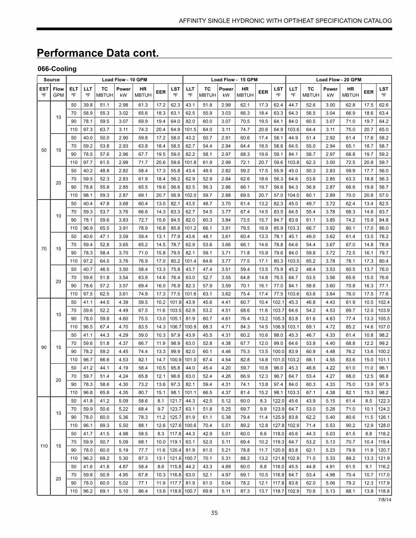
35
Performance Data cont.066-Cooling
Source Load Flow - 10 GPM Load Flow - 15 GPM Load Flow - 20 GPM
ESTºF
FlowGPM
ELTºF
LLTºF
TCMBTUH
PowerkW
HRMBTUH EER LST
ºFLLTºF
TCMBTUH
PowerkW
HRMBTUH EER LST
ºFLLTºF
TCMBTUH
PowerkW
HRMBTUH EER LST
ºF
50
10
50 39.8 51.1 2.98 61.3 17.2 62.3 43.1 51.8 2.99 62.1 17.3 62.4 44.7 52.6 3.00 62.8 17.5 62.6
70 58.9 55.3 3.02 65.6 18.3 63.1 62.5 55.9 3.03 66.3 18.4 63.3 64.3 56.5 3.04 66.9 18.6 63.4
90 78.1 59.5 3.07 69.9 19.4 64.0 82.0 60.0 3.07 70.5 19.5 64.1 84.0 60.5 3.07 71.0 19.7 64.2
110 97.3 63.7 3.11 74.3 20.4 64.9 101.5 64.0 3.11 74.7 20.6 64.9 103.6 64.4 3.11 75.0 20.7 65.0
15
50 40.0 50.0 2.90 59.8 17.2 58.0 43.2 50.7 2.91 60.6 17.4 58.1 44.9 51.4 2.92 61.4 17.6 58.2
70 59.2 53.8 2.93 63.8 18.4 58.5 62.7 54.4 2.94 64.4 18.5 58.6 64.5 55.0 2.94 65.1 18.7 58.7
90 78.5 57.6 2.96 67.7 19.5 59.0 82.2 58.1 2.97 68.3 19.6 59.1 84.1 58.7 2.97 68.8 19.7 59.2
110 97.7 61.5 2.99 71.7 20.6 59.6 101.8 61.9 2.99 72.1 20.7 59.6 103.8 62.3 3.00 72.5 20.8 59.7
20
50 40.2 48.8 2.82 58.4 17.3 55.8 43.4 49.5 2.82 59.2 17.5 55.9 45.0 50.3 2.83 59.9 17.7 56.0
70 59.5 52.3 2.83 61.9 18.4 56.2 62.9 52.9 2.84 62.6 18.6 56.3 64.6 53.6 2.85 63.3 18.8 56.3
90 78.8 55.8 2.85 65.5 19.6 56.6 82.5 56.3 2.86 66.1 19.7 56.6 84.3 56.8 2.87 66.6 19.8 56.7
110 98.1 59.3 2.87 69.1 20.7 56.9 102.0 59.7 2.88 69.5 20.7 57.0 104.0 60.1 2.89 70.0 20.8 57.0
70
10
50 40.4 47.8 3.68 60.4 13.0 82.1 43.5 48.7 3.70 61.4 13.2 82.3 45.0 49.7 3.72 62.4 13.4 82.5
70 59.3 53.7 3.76 66.6 14.3 83.3 62.7 54.5 3.77 67.4 14.5 83.5 64.5 55.4 3.78 68.3 14.6 83.7
90 78.1 59.6 3.83 72.7 15.6 84.5 82.0 60.3 3.84 73.5 15.7 84.7 83.9 61.1 3.85 74.2 15.9 84.8
110 96.9 65.5 3.91 78.9 16.8 85.8 101.2 66.1 3.91 79.5 16.9 85.9 103.3 66.7 3.92 80.1 17.0 86.0
15
50 40.6 47.1 3.59 59.4 13.1 77.9 43.6 48.1 3.61 60.4 13.3 78.1 45.1 49.0 3.62 61.4 13.5 78.2
70 59.4 52.8 3.65 65.2 14.5 78.7 62.9 53.6 3.66 66.1 14.6 78.8 64.6 54.4 3.67 67.0 14.8 78.9
90 78.3 58.4 3.70 71.0 15.8 79.5 82.1 59.1 3.71 71.8 15.9 79.6 84.0 59.8 3.72 72.5 16.1 79.7
110 97.2 64.0 3.76 76.9 17.0 80.2 101.4 64.6 3.77 77.5 17.1 80.3 103.5 65.2 3.78 78.1 17.3 80.4
20
50 40.7 46.5 3.50 58.4 13.3 75.8 43.7 47.4 3.51 59.4 13.5 75.9 45.2 48.4 3.53 60.5 13.7 76.0
70 59.6 51.8 3.54 63.9 14.6 76.4 63.0 52.7 3.55 64.8 14.8 76.5 64.7 53.5 3.56 65.6 15.0 76.6
90 78.6 57.2 3.57 69.4 16.0 76.9 82.3 57.9 3.59 70.1 16.1 77.0 84.1 58.6 3.60 70.8 16.3 77.1
110 97.5 62.5 3.61 74.9 17.3 77.5 101.6 63.1 3.62 75.4 17.4 77.5 103.6 63.6 3.64 76.0 17.5 77.6
90
10
50 41.1 44.5 4.39 59.5 10.2 101.9 43.9 45.6 4.41 60.7 10.4 102.1 45.3 46.8 4.43 61.9 10.5 102.4
70 59.6 52.2 4.49 67.5 11.6 103.5 62.9 53.2 4.51 68.6 11.8 103.7 64.6 54.2 4.53 69.7 12.0 103.9
90 78.0 59.8 4.60 75.5 13.0 105.1 81.9 60.7 4.61 76.4 13.2 105.3 83.8 61.6 4.63 77.4 13.3 105.5
110 96.5 67.4 4.70 83.5 14.3 106.7 100.9 68.3 4.71 84.3 14.5 106.9 103.1 69.1 4.72 85.2 14.6 107.0
15
50 41.1 44.3 4.29 59.0 10.3 97.9 43.9 45.5 4.31 60.2 10.6 98.0 45.3 46.7 4.33 61.4 10.8 98.2
70 59.6 51.8 4.37 66.7 11.9 98.9 63.0 52.8 4.38 67.7 12.0 99.0 64.6 53.8 4.40 68.8 12.2 99.2
90 78.2 59.2 4.45 74.4 13.3 99.9 82.0 60.1 4.46 75.3 13.5 100.0 83.9 60.9 4.48 76.2 13.6 100.2
110 96.7 66.6 4.53 82.1 14.7 100.9 101.0 67.4 4.54 82.8 14.8 101.0 103.2 68.1 4.55 83.6 15.0 101.1
20
50 41.2 44.1 4.19 58.4 10.5 95.8 44.0 45.4 4.20 59.7 10.8 96.0 45.3 46.6 4.22 61.0 11.0 96.1
70 59.7 51.4 4.24 65.8 12.1 96.6 63.0 52.4 4.26 66.9 12.3 96.7 64.7 53.4 4.27 68.0 12.5 96.8
90 78.3 58.6 4.30 73.2 13.6 97.3 82.1 59.4 4.31 74.1 13.8 97.4 84.0 60.3 4.33 75.0 13.9 97.5
110 96.8 65.8 4.35 80.7 15.1 98.1 101.1 66.5 4.37 81.4 15.2 98.1 103.3 67.1 4.38 82.1 15.3 98.2
110
10
50 41.8 41.2 5.09 58.6 8.1 121.7 44.3 42.5 5.12 60.0 8.3 122.0 45.6 43.9 5.15 61.4 8.5 122.3
70 59.9 50.6 5.22 68.4 9.7 123.7 63.1 51.8 5.25 69.7 9.9 123.9 64.7 53.0 5.28 71.0 10.1 124.2
90 78.0 60.0 5.36 78.3 11.2 125.7 81.9 61.1 5.38 79.4 11.4 125.9 83.8 62.2 5.40 80.6 11.5 126.1
110 96.1 69.3 5.50 88.1 12.6 127.6 100.6 70.4 5.51 89.2 12.8 127.8 102.9 71.4 5.53 90.2 12.9 128.0
15
50 41.7 41.5 4.98 58.5 8.3 117.8 44.3 42.9 5.01 60.0 8.6 118.0 45.6 44.3 5.03 61.5 8.8 118.2
70 59.9 50.7 5.09 68.1 10.0 119.1 63.1 52.0 5.11 69.4 10.2 119.3 64.7 53.2 5.13 70.7 10.4 119.4
90 78.0 60.0 5.19 77.7 11.6 120.4 81.9 61.0 5.21 78.8 11.7 120.5 83.8 62.1 5.23 79.9 11.9 120.7
110 96.2 69.2 5.30 87.3 13.1 121.6 100.7 70.1 5.31 88.2 13.2 121.8 102.9 71.0 5.33 89.2 13.3 121.9
20
50 41.6 41.8 4.87 58.4 8.6 115.8 44.2 43.3 4.89 60.0 8.8 116.0 45.5 44.8 4.91 61.5 9.1 116.2
70 59.8 50.9 4.95 67.8 10.3 116.8 63.0 52.1 4.97 69.1 10.5 116.9 64.7 53.4 4.98 70.4 10.7 117.0
90 78.0 60.0 5.02 77.1 11.9 117.7 81.9 61.0 5.04 78.2 12.1 117.8 83.8 62.0 5.06 79.2 12.3 117.9
110 96.2 69.1 5.10 86.4 13.6 118.6 100.7 69.8 5.11 87.3 13.7 118.7 102.9 70.6 5.13 88.1 13.8 118.8
7/8/14
AFFINITY SINGLE HYDRONIC WITH OPTIHEAT SPECIFICATION CATALOG

36
Wiring Schematics
Blue240V
CCT2 T1
Compressor
C
R
SBlue
L1L2
Tan(10)
Capacitor
HW
HW
Black
Black
Orange
Orange
SCT
P8
MO
TOR P6
RS4
85 P7
ZON
E P9
ABC
STEP
PER
ANA
ACC
2D
HD
IV
NO
CO
M
K6
NO
CO
M
K5
C L1 L1 L2 L2P1
2P1
0P5
P11
CR(-)(+) CR(-)(+) CR(-)(+)
P4P2
K1K2
K3
HA2
HA1
SGI
LOO
PVS
DAT
AVS
PU
MP
PUM
PSL
AVE
P3
R
V+CRTXRX +5
P14
LLT
P1LA
TFL
OW
LWT
EWT
CT2
43
CT2
43
CT1
21
CT1
21
Status
G
DIS
CH
P16
P17
P18
P15
(Aurora Expansion Board)
AXB™
SW1
Modbus Add. ID
Future Use
1
23
4
5
ONOFF
Future Use
Acc 2 – Dip 4
Acc 2 – Dip 5
CS
+5C
S+5
21
CC
INO
UT
T
VIV Line Tem
p
1
2
3
4
+
X1
X2
Y1
5 Y2
VIV Stepper Motor
5A Circuit Breaker
5A Circuit Breaker
1
2
PB2
2
1
208-230/60/1
Pump
G
PumpExt Pump
1/2 hp Total
Variable Speed Pump
208-230/60/1
VSPump G
NOTE 2
Black
Orange
RedYellow
Gray
Blue
Blue
GNDOUT5DC
123SU
C P White
Red
Black VIV Pressure Transducer
Pump Slave Input/Output
Smart Grid
Home Automation
NOTE: 3
Blue321
4
10DCGNDPWM
123
NA 4
VARIABLE SPEED PUMP
LOW VOLTAGEBrown
Black
Future Use
Accessory 2 Output
1
2
PB1
2
1
208-230/60/1 GPumpLoad Pump
5A Circuit Breaker
5A Circuit Breaker
OAT
Sen
sor
Geo
Tank
Sen
sor
OAT
OAT
Tank
Tank
Red
(GN
D)
Red
(TS)
Brow
n (O
AT)
Brow
n (G
ND
)
HydroZone Controller
GNDTS
OATGNDB+A+
HZ
RC
O/BPV
C1C2C3C4
L
NOTE 4
Notes1 - Switch blue and red wires for 208V operation.
2 – Variable speed pump power wires to connect the pump to L1 and L2 on the AXB board are provided with variable speed flow center.
3 – Variable speed pump low voltage wire harness provided with variable speed flow center.
4 – HydroZone controller is optional field installed accessory.
Black
Red
White
WhiteNot Used
Violet/White (8)
Violet/White (9) Black/White (2)
Black/White (1)
Violet (7)
Violet (6)
Black (4)
Black (5)
Orange (11)
Brown (12)
5 – Reversing Valve wires not installed on heating only option
LPR
LPR
NO
NC
COM
Black/White (3)
24 VDC
6 – FP2 is replaced with a resistor on heating only option
LPR
NO
NC
COM
Black/White (3)
CC-T1
NOTE 7
7 – Move black/white(3) wire when HydroZone is not used for pump control
Geothermal Tank Thermostat
Y1
NOTE 8
RAurora Board
8 – When Geothermal Storage Tank directly with Aurora Board
Aurora Advanced EVI Water-Water 208-230/60/1
AFFINITY SINGLE HYDRONIC WITH OPTIHEAT SPECIFICATION CATALOG
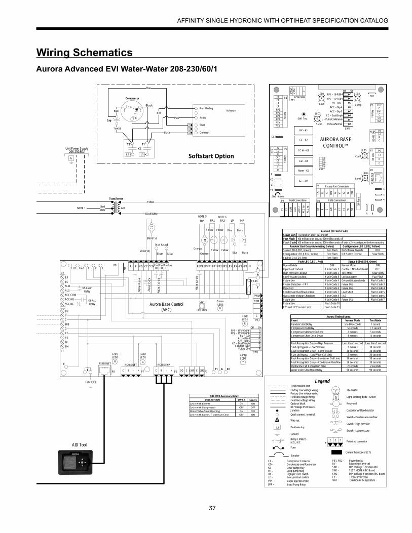
37
Wiring Schematics
Transformer
24V
CC
HP
Black
Black
Blue
Blue
LP
T
Yellow
Yellow
FP1
Black(15)
Violet(14)
Green(13)
Black/White
Yellow
Red208V
G
208-230/60/1Unit Power Supply
AID Tool
DESCRIPTION SW2-4 SW2-5Cycle with Blower ON ONCycle with Compressor OFF OFFWater Valve Slow Opening ON OFFCycle with Comm. T-stat Hum Cmd OFF ON
ABC SW2 Accessory Relay
Aurora LED Flash Codes
Status LED (LED3, Green)
Status LED (LED1, Green)Configuration LED (LED2, Yellow)Fault LED (LED3, Red)
Random Start Delay (Alternating Colors)Fast FlashFast FlashFast Flash
1 second on and 1 second off100 milliseconds on and 100 milliseconds off100 milliseconds on and 400 milliseconds off with a 2 second pause before repeating
Slow FlashFast FlashFlash Code
Normal ModeControl is Non-FunctionalTest ModeLockout ActiveDehumidification ModeFuture UseFuture UseLoad ShedESD
OFFON
Slow FlashFast Flash
Flash Code 2Flash Code 3
Flash Code 6
Flash Code 4Flash Code 5
Future Use Flash Code 7
Configuration LED (LED2, Yellow)No Software Overide OFFDIP Switch Overide Slow Flash
Fault LED (LED1, Red)Normal ModeInput Fault LockoutHigh Pressure LockoutLow Pressure LockoutFuture UseFreeze Detection – FP1ReservedCondensate Overflow LockoutOver/Under Voltage ShutdownFuture UseFuture UseFP1 and FP2 Sensor Error
Flash Code 1OFF
Flash Code 2Flash Code 3Flash Code 4Flash Code 5
Flash Code 8
Flash Code 6Flash Code 7
Flash Code 9Flash Code 10Flash Code 11
CFM
P13
P4
SW1
P5JW2
P9
LO
O/B
Y2
W
DH
P8 P7
RS485 NET RS485 NET
P6
RS485 EXP
P3
SW2
On
Future Use L Output Type
CC – Dual/SingleAcc – Dip 5Acc – Dip 4
RV – B/OFP2 – 15°F/30°FFP1 – 15°F/30°F
Com1LED5
Com2LED5
Test Mode
F1-3A
P1
C
PWM
12345678
ALM
ALG
ACC COM
ACC NO
ACC NC
R
C
G
Y1
EH2CEH1CCOC R - +C R - +
Off
FaultLED1
R
StatusLED3
ConfigLED2
CC2 CC F CR F FG CC CCG
CC2HI
CC2LO
CC2G
REV REV FP1 FP1 FP2 FP2 LPS LPS HPS HPS
Aurora Base Control(ABC)
K1-RV R
elay
K2-CC
Relay
K3-CC
2 Relay
K4-Fan Relay
K5-Alarm Relay
K6-Acc Relay
F
R
C
CCGY1C
R
ES
LS
P2
EH1
YG G
G
CC2
Fact
ory
Fault
ALG
ALM
LSES
ACC
c
Status
AURORA BASE CONTROL™
RV – K1
CC
2
CC – K2
CC Hi – K3
Fan – K4
Alarm – K5
Acc – K6
ACC
no
ACC
nc
O/BCRLO G Y1 Y2 W DH
3A-F
use
O/BCRLO G Y1 Y2 W DH
LOG
HICCGCCFGFR
HPHPLP
FP2FP2FP1
REVREV
CFM
PWM
ECM PWM
Fact
ory
Factory Fan Connection
R R
CC
C
C
R
(-)
(+)
RS
485
EH2C
EH1C
CO
(+)(-)RCR
S485
Exp
Fact
ory
Com1
Com2
Config
G
G
G
YR
SW1 Test
FP1 – 15oF/30oF
JW2 - Alarm
P11
P5
P2 P1
P8
P7
P9
P6
P3
SW2
P13P4 FP2 – 15oF/30oF
RV – B/O
ACC – Dip 4
ACC – Dip 5
CC – Dual/Single L – Pulse/Continuous
Reheat/Normal
Fact
ory
Use
Field ConnectionsField Connections
C
LP
FP1
F
CC
G
Y1
1
2
3
4
5
6
7
8
Off On
N/A
RS4
85 N
ET
EH1LED1 LED2
LED3
LED4
LED5
T2 T1
Compressor
C
R
SBlue
Tan(6)
Cap
Run Winding
Active
Start
Common
SoftstartRed
Pink
Black
Blue
CCT2 T1
L1L2 Softstart Option
NOTE 1
Black
BlueBlue
Not Used
Orange
Orange
T
Yellow
Yellow
FP2
RV
RVNOTE 5
Current Transducer (CT)
Thermistor
Light emitting diode - Green
Relay coil
Capacitor w/ bleed resistor
Switch - Condensate overflow
Switch - High pressure
Switch - Low pressure
Polarized connector
Factory Low voltage wiringFactory Line voltage wiringField low voltage wiringField line voltage wiringOptional blockDC Voltage PCB tracesJunction
Quick connect terminal
Wire nut
Field wire lug
Ground
Fuse
CC -CO -K6 -K5 -
FP -HP - LP -
PB1, PB2 - RV -SW1 -SW1 -SW2 -
Compressor ContactorCondensate overflow sensorDHW pump relayLoop pump relay
Freeze ProtectionHigh pressure switchLow pressure switch
Power blocksReversing Valve coilDIP package 5 position AXBTEST MODE ABC BoardDIP package 8 position ABC Board
Legend
Relay Contacts-N.O., N.C.
G
T
132P
L1
Breaker
Vapor Injection Valve VIV - LPR - Load Pump Relay
OAT - Outdoor Air Temperature
Field Installed Item
Event Normal Mode Test ModeRandom Start DelayCompressor On DelayCompressor Minimum On TimeCompressor Short Cycle Delay
Fault Recognition Delay – High PressureStart-Up Bypass – Low PressureFault Recognition Delay – Low PressureStart-Up Bypass – Low Water Coil LimitFault Recognition Delay – Low Water Coil LimitFault Recognition Delay – Condensate OverflowHydroZone Call Recognition Time
Less than 1 second
5 to 80 seconds 1 second5 seconds < 1 second
Less than 1 second
2 minutes 5 seconds4 minutes 15 seconds
2 minutes
2 minutes
30 seconds30 seconds 30 seconds
30 seconds30 seconds
30 seconds30 seconds30 seconds
2 seconds 2 seconds
Aurora Timing Events
Water Valve Slow Open Delay 90 seconds 90 seconds
NOTE 6
Aurora Advanced EVI Water-Water 208-230/60/1
AFFINITY SINGLE HYDRONIC WITH OPTIHEAT SPECIFICATION CATALOG
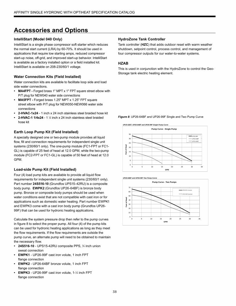
38
IntelliStart (Model 040 Only)IntelliStart is a single phase compressor soft starter which reduces the normal start current (LRA) by 60-70%. It should be used in applications that require low starting amps, reduced compressor start-up noise, off-grid, and improved start-up behavior. IntelliStart is available as a factory installed option or a field installed kit. IntelliStart is available on 208-230/60/1 voltage.
Water Connection Kits (Field Installed)Water connection kits are available to facilitate loop side and load side water connections.• MA4FPT - Forged brass 1" MPT x 1" FPT square street elbow with
P/T plug for NEW040 water side connections• MA5FPT - Forged brass 1.25" MPT x 1.25" FPT square
street elbow with P/T plug for NEW050-NEW066 water side connections
• 2-HVAC-1x24 - 1 inch x 24 inch stainless steel braided hose kit• 2-HVAC-1 1/4x24 - 1 1⁄4 inch x 24 inch stainless steel braided
hose kit
Earth Loop Pump Kit (Field Installed)A specially designed one or two-pump module provides all liquid flow, fill and connection requirements for independent single unit systems (230/60/1 only). The one-pump module (FC1-FPT or FC1-GL) is capable of 25 feet of head at 12.0 GPM, while the two-pump module (FC2-FPT or FC1-GL) is capable of 50 feet of head at 12.0 GPM.
Load-side Pump Kit (Field Installed)Four (4) load pump kits are available to provide all liquid flow requirements for independent single unit systems (230/60/1 only). Part number 24S516-10 (Grundfos UPS15-42RU) is a composite body pump. EWPK2 (Grundfos UP26-64BF) is bronze body pump. Bronze or composite body pumps should be used when water conditions exist that are not compatible with cast iron or for applications such as domestic water heating. Part number EWPK1 and EWPK3 come with a cast iron body pump (Grundfos UP26-99F) that can be used for hydronic heating applications.
Calculate the system pressure drop then refer to the pump curves in figure 8 to select the proper pump. All four (4) of the pump kits can be used for hydronic heating applications as long as they meet the flow requirements. If the flow requirements are outside the pump curve, an alternate pump will need to be obtained to maintain the necessary flow.• 24S516-10 - UPS15-42RU composite PPS, 3⁄4 inch union
sweat connection• EWPK1 - UP26-99F cast iron volute, 1 inch FPT
flange connection• EWPK2 - UP26-64BF bronze volute, 1 inch FPT
flange connection• EWPK3 - UP26-99F cast iron volute, 1-1⁄4 inch FPT
flange connection
Figure 8: UP26-64BF and UP26-99F Single and Two Pump Curve
Accessories and OptionsHydroZone Tank ControllerTank controller (HZC) that adds outdoor reset with warm weather shutdown, setpoint control, process control, and management of four compressor outputs for our water-to-water systems.
HZABThis is used in conjunction with the HydroZone to control the Geo-Storage tank electric heating element.
UP15-42B7, UP26-64BF and UP26-99F Single Pump Curve
UP26-64BF and UP26-99F Two Pump Curve
0
5
10
15
20
25
30
35
0 5 10 15 20 25 30 35
Feet
of H
ead
GPM
Pump Curve - Single Pump
UP26-99F
UP26-64BF
UP15-42B7
0
10
20
30
40
50
60
70
0 5 10 15 20 25 30 35
Feet
of H
ead
GPM
Pump Curve - Two Pumps
UP26-99F (2 pumps)
UP26-64BF (2pumps)
AFFINITY SINGLE HYDRONIC WITH OPTIHEAT SPECIFICATION CATALOG
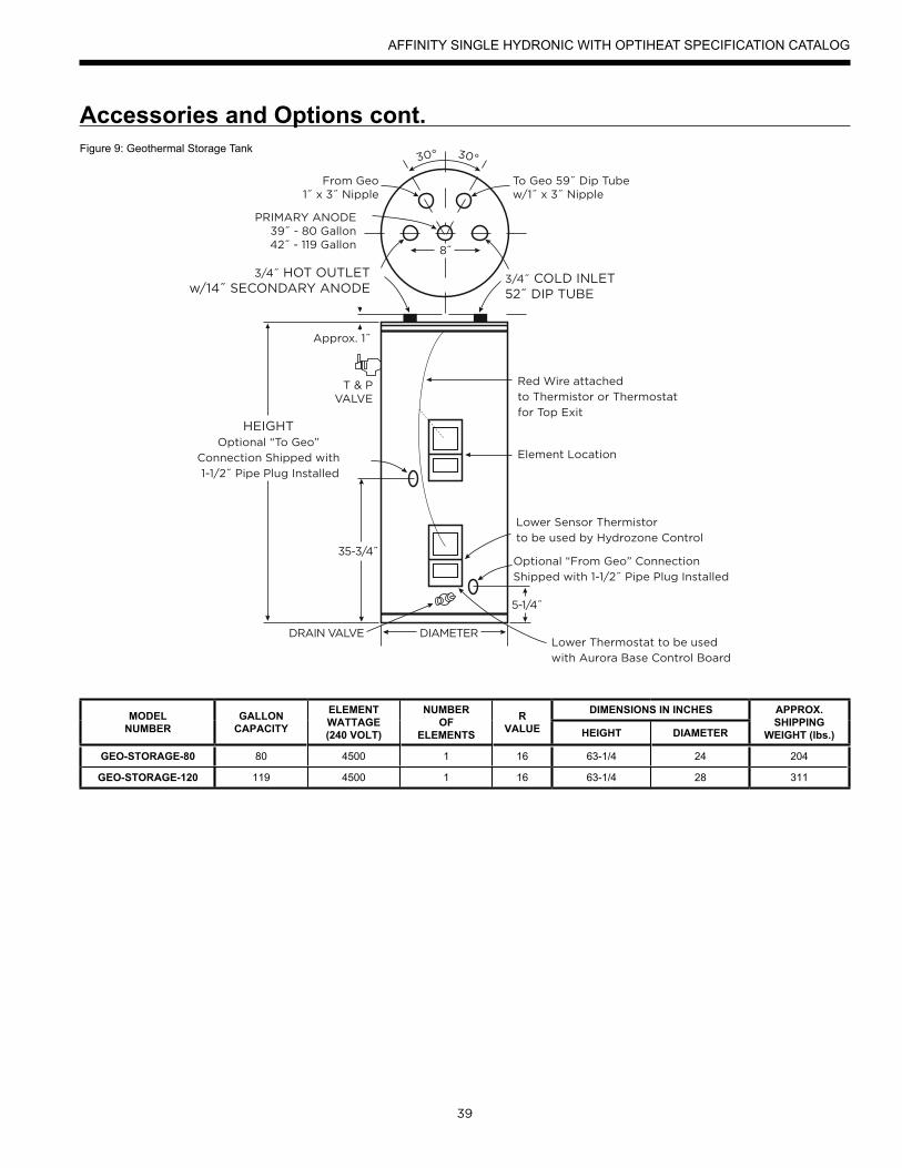
39
Accessories and Options cont.Figure 9: Geothermal Storage Tank
30° 30°
To Geo 59˝ Dip Tubew/1˝ x 3˝ Nipple
Approx. 1˝
T & PVALVE
From Geo1˝ x 3˝ Nipple
PRIMARY ANODE39˝ - 80 Gallon42˝ - 119 Gallon
3/4˝ COLD INLET52˝ DIP TUBE
3/4˝ HOT OUTLETw/14˝ SECONDARY ANODE
HEIGHTOptional “To Geo”
Connection Shipped with
1-1/2˝ Pipe Plug Installed
Element Location
Red Wire attached
to Thermistor or Thermostat
for Top Exit
Lower Sensor Thermistor
to be used by Hydrozone Control
Optional “From Geo” Connection
Shipped with 1-1/2˝ Pipe Plug Installed
DIAMETER
8˝
5-1/4˝
35-3/4˝
Lower Thermostat to be used
with Aurora Base Control Board
DRAIN VALVE
MODELNUMBER
GALLONCAPACITY
ELEMENTWATTAGE(240 VOLT)
NUMBEROF
ELEMENTS
RVALUE
DIMENSIONS IN INCHES APPROX.SHIPPING
WEIGHT (lbs.)HEIGHT DIAMETER
GEO-STORAGE-80 80 4500 1 16 63-1/4 24 204
GEO-STORAGE-120 119 4500 1 16 63-1/4 28 311
AFFINITY SINGLE HYDRONIC WITH OPTIHEAT SPECIFICATION CATALOG
40
Engineering Guide Specifi cationsGeneralThe liquid source water-to-water heat pump shall be a single packaged heating only or reverse-cycle heating/cooling unit. The unit shall be listed by a nationally recognized safety-testing laboratory or agency, such as ETL Testing Laboratory, Underwriters Laboratory (UL), or Canadian Standards Association (CSA). The unit shall be rated in accordance with Air Conditioning, Heating, and Refrigeration Institute/International Standards Organization (AHRI/ISO) and Canadian Standards Association (CSA-US). The liquid source water-to-water heat pump unit, as manufactured by WaterFurnace International, Fort Wayne, Indiana, shall be designed to operate with source liquid temperatures between 50°F [10°C] and 110°F [43.3°C] in cooling, and between 30°F [-1°C] and 90°F [32.2°C] in heating.
Casing and CabinetThe cabinet shall be fabricated from heavy-gauge galvanized steel and finished with corrosion-resistant powder coating. This corrosion protection system shall meet the stringent 1,000 hour salt spray test per ASTM B117. The interior shall be insulated with 1⁄2 in. thick, multi-density, coated glass fiber for noise suppression.
All units shall have separate holes and knockouts for entrance of line voltage and low voltage control wiring. All factory-installed wiring passing through factory knockouts and openings shall be protected from sheet metal edges at openings by plastic ferrules. The control box shall be field switchable from front to back for improved application flexibility with quick attach low voltage harnesses. The control box is shipped standard on the opposite end of the water connections.
Refrigerant CircuitAll units shall utilize the non-ozone depleting and low global warming potential refrigerant R-410A. All units shall contain a sealed refrigerant circuit including a hermetic motor-compressor, bidirectional thermostatic expansion valve, reversing valve, coaxial tube water-to-refrigerant heat exchanger, electronic expansion valve (VI circuit), and service ports.
Compressors shall be high-efficiency scroll type designed for vapor injection, heat pump duty and mounted on vibration isolators. The compressor shall be double isolation mounted using selected durometer grommets to provide vibration free compressor mounting. All models will feature a compressor discharge muffler to help quiet compressor gas pulsations. A high density sound attenuating blanket shall be factory installed around the compressor to reduce sound. Compressor motors shall be single-phase PSC with overload protection.
The coaxial water-to-refrigerant heat exchanger shall be designed for low water pressure drop and constructed of a convoluted copper inner tube and a steel outer tube. Refrigerant-to-water heat exchangers shall be of copper inner water tube and steel refrigerant outer tube design, rated to withstand 650 PSIG (4481 kPa) working refrigerant pressure and 450 PSIG (3101 kPa) working water pressure. The thermostatic expansion valve shall provide proper superheat over the entire liquid temperature range with minimal “hunting.” The valve shall operate bidirectionally without the use of check valves.
Piping and ConnectionsSupply and return water connections shall be 1 in. [25.4 mm] for the 040, 1 1⁄4 in. [31.75 mm] for the 050-066. The FPT fittings shall be fixed to the cabinet by use of a captive fitting, which eliminates the need for backup pipe wrenches.
ElectricalA control box shall be located within the unit compressor compartment and shall contain a 75VA transformer with a built-in circuit breaker, 24 volt activated compressor contactor, terminal block for thermostat wiring and solid-state controller for complete unit operation. Electromechanical operation WILL NOT be accepted. Units shall be name-plated for use with time delay fuses or HACR circuit breakers. Unit controls shall be 24 volt and provide heating or cooling as required by the remote thermostat/sensor.
A standard microprocessor-based controller that interfaces with an electronic thermostat to monitor and control unit operation shall be provided. The control shall provide operational sequencing, high and low pressure switch monitoring, freeze detection, lockout mode control, loop pump control, LED status and fault indicators, fault memory, field selectable options and accessory output. The control shall provide fault retry three times before locking out to limit nuisance trips. Anti short-cycle protection shall be integral to the control.
A detachable terminal block with screw terminals will be provided for field control wiring. All units shall have knockouts for entrance of low and line voltage wiring.
Optional IntelliStart (compressor Soft Starter) shall be factory installed for use in applications that require low starting amps, reduced compressor start-up noise, off-grid, and improved start-up behavior. IntelliStart shall reduce normal starting current by 60% on 208-230/60/1 units.
AFFINITY SINGLE HYDRONIC WITH OPTIHEAT SPECIFICATION CATALOG

41
Engineering Guide Specifi cations cont.AccessoriesHose Kits – Automatic Balancing and Ball Valves with ‘Y’ strainer (field-installed)P/N - HHK81S (1 in. hose kit for 040) HHK100S (1 1⁄4 in. hose kit for 050-066)A flexible steel braid hose featuring Kevlar® reinforced EPDM core with ANSI 302/304 stainless steel outer braid and fire rated materials per ASTM E 84-00 (NFPA 255, ANSI/UL 723 & UBC 8-1). Ball valve at one end; swivel connector with adapter at the other end (swivel to adapter connection via fiber or EPDM gasket). Swivel connection provides union between heat pump and piping system. The hoses feature brass fittings, stainless steel ferrules. A “y” strainer is provided on one end for fluid straining and integral “blowdown” valve. A full port ball valve shall be provided with integral P/T (pressure/temperature) port on supply hose and automatic balancing valve with integral P/T ports and full port ball valve on return hose.
Specifications:• Temperature range of 35°F [2°C] to 180°F [82°C].• Max. working pressure of 400 psi [2756 kPa] for 1⁄2 in. and 3⁄4 in. hose kits; max. working pressure of 350 psi [2413 kPa] for 1 in. and 1 1⁄4 in. hose kits.• Minimum burst pressure of four times working pressure.
AFFINITY SINGLE HYDRONIC WITH OPTIHEAT SPECIFICATION CATALOG

42
Notes
AFFINITY SINGLE HYDRONIC WITH OPTIHEAT SPECIFICATION CATALOG

43
Revision GuidePages: Description: Date: By:30-35 Updated Heating Performance Data 01 May 2015 MA
All Literature Creation 05 Feb 2015 MA
AFFINITY SINGLE HYDRONIC WITH OPTIHEAT SPECIFICATION CATALOG


©2015 The manufacturer has a policy of continual product research and development and reserves the right to change design and specifi cations without notice.
Product: Affi nity Series with OptiHeatType: Water-to-Water Geothermal Heat PumpsSize: 3-6 Ton Single Speed
Document Type: Specifi cation CatalogPart Number: SC2508WK6Release Date: 05/15
York and Affi nity are registered trademarks of Johnson Controls, Inc., and are used with permission.