heating coilsarmstrongflow.com.au/.../04/section-11-heating-coils.pdf · 2017-11-17 · heating...
TRANSCRIPT
351ARMSTRONG PRODUCT CATALOGUE
Heating Coils
SECTION
11
352ARMSTRONG PRODUCT PAGES
http://armstrongflow.com.au/downloads/1082
Heating Coils SECTION
11H
eatin
g an
d Co
olin
g Co
ils
336North America • Latin America • India • Europe / Middle East / Africa • China • Pacifi c Rim
armstronginternational.com
Designs, materials, weights and performance ratings are approximate and subject to change without notice. Visit www.armstronginternational.com for up-to-date information.
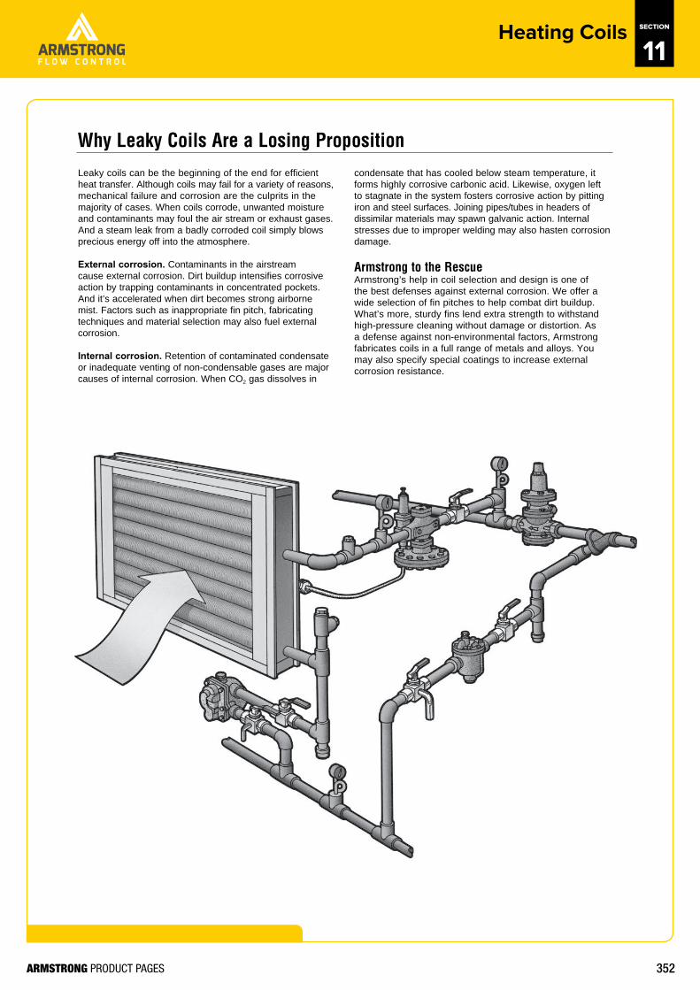
Leaky coils can be the beginning of the end for efficientheat transfer. Although coils may fail for a variety of reasons, mechanical failure and corrosion are the culprits in themajority of cases. When coils corrode, unwanted moisture and contaminants may foul the air stream or exhaust gases. And a steam leak from a badly corroded coil simply blows precious energy off into the atmosphere.
External corrosion. Contaminants in the airstream cause external corrosion. Dirt buildup intensifies corrosive action by trapping contaminants in concentrated pockets. And it’s accelerated when dirt becomes strong airborne mist. Factors such as inappropriate fin pitch, fabricating techniques and material selection may also fuel external corrosion.
Internal corrosion. Retention of contaminated condensate or inadequate venting of non-condensable gases are major causes of internal corrosion. When CO2 gas dissolves in
condensate that has cooled below steam temperature, it forms highly corrosive carbonic acid. Likewise, oxygen left to stagnate in the system fosters corrosive action by pitting iron and steel surfaces. Joining pipes/tubes in headers of dissimilar materials may spawn galvanic action. Internal stresses due to improper welding may also hasten corrosion damage.
Armstrong to the RescueArmstrong’s help in coil selection and design is one of the best defenses against external corrosion. We offer a wide selection of fin pitches to help combat dirt buildup. What’s more, sturdy fins lend extra strength to withstand high-pressure cleaning without damage or distortion. As a defense against non-environmental factors, Armstrong fabricates coils in a full range of metals and alloys. You may also specify special coatings to increase external corrosion resistance.
Why Leaky Coils Are a Losing Proposition
353ARMSTRONG PRODUCT PAGES
http://armstrongflow.com.au/downloads/1082
Heating Coils SECTION
11H
eating and Cooling Coils
337North America • Latin America • India • Europe / Middle East / Africa • China • Pacifi c Rim
armstronginternational.com
Designs, materials, weights and performance ratings are approximate and subject to change without notice. Visit www.armstronginternational.com for up-to-date information.
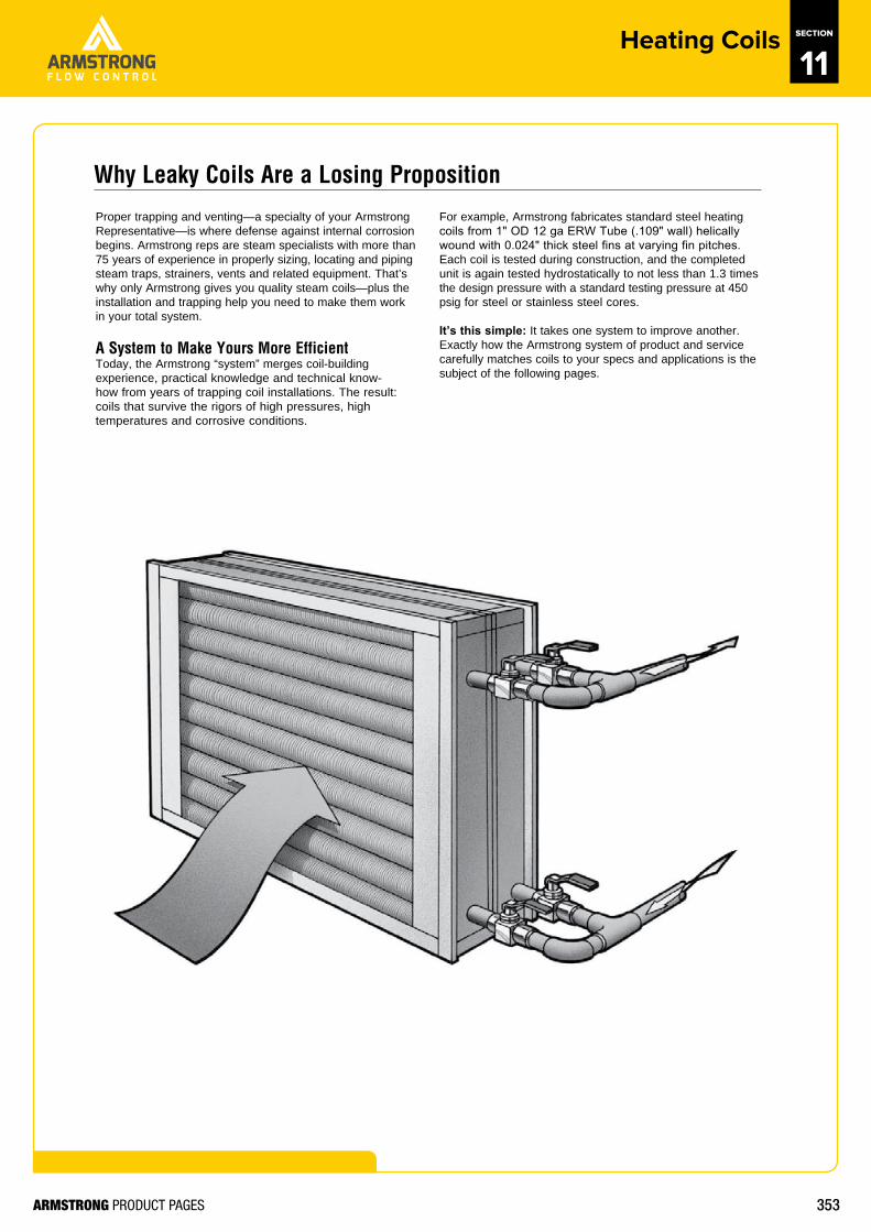
Proper trapping and venting—a specialty of your Armstrong Representative—is where defense against internal corrosion begins. Armstrong reps are steam specialists with more than 75 years of experience in properly sizing, locating and piping steam traps, strainers, vents and related equipment. That’s why only Armstrong gives you quality steam coils—plus the installation and trapping help you need to make them work in your total system.
A System to Make Yours More EfficientToday, the Armstrong “system” merges coil-building experience, practical knowledge and technical know-how from years of trapping coil installations. The result: coils that survive the rigors of high pressures, high temperatures and corrosive conditions.
For example, Armstrong fabricates standard steel heating coils from 1" OD 12 ga ERW Tube (.109" wall) helically wound with 0.024" thick steel fins at varying fin pitches. Each coil is tested during construction, and the completed unit is again tested hydrostatically to not less than 1.3 times the design pressure with a standard testing pressure at 450 psig for steel or stainless steel cores.
It’s this simple: It takes one system to improve another. Exactly how the Armstrong system of product and service carefully matches coils to your specs and applications is the subject of the following pages.
Why Leaky Coils Are a Losing Proposition
354ARMSTRONG PRODUCT PAGES
http://armstrongflow.com.au/downloads/1082
Heating Coils SECTION
11H
eatin
g an
d Co
olin
g Co
ils
338North America • Latin America • India • Europe / Middle East / Africa • China • Pacifi c Rim
armstronginternational.com
Designs, materials, weights and performance ratings are approximate and subject to change without notice. Visit www.armstronginternational.com for up-to-date information.
The choice of tube material depends upon severalimportant factors:• The corrosive quality of the steam or liquid medium• The ability to pipe, trap and vent steam coils effectively• The size and service requirements of the installation• The external corrosion to which the coils are likely to be
subjected
Generally speaking, the heat transfer characteristics of the tube material are of little consequence. The table on the next page illustrates the relative effect of tube materials on overall heat transfer. Because the fin area constitutes the vast majority of the heat transfer surface, it is the most important factor determining heat transfer effectiveness. Therefore, the choice of tube materials should be based on service requirements, not heat transfer efficiency.
Internal corrosion. The base material found in the 6000 Series coils is steel. The minimum wall thickness is .109" for steam coils and liquid coils, which affords both strength and corrosion resistance. All Armstrong coils are of monometallic design, which means that all wetted parts are made of the same materials. This precludes the likelihood of galvanic corrosion often experienced in coils made of dissimilar materials. For most applications, steel will provide very satisfactory service. In order to do this, however, steam coils must be carefully piped, trapped and vented to ensure good condensate and non-condensable gas evacuation.
There are many cases where the steam cannot be conditioned enough to be non-corrosive or it is not possible to pipe, trap and vent the coils properly. For those areas, Armstrong recommends stainless steel wetted parts. Choosing which of these is most appropriate depends on the degree and type of problem as well as the steam pressure involved.
External corrosion. In the case of external corrosion, factors concerning the corrosiveness of the airstream enter into the decision. The choice of steel or stainless steel for the wetted parts depends on the compatibility of those materials with the contaminants in the airstream. In addition to the base materials available, Armstrong also offers hot dipped galvanizing, epoxy dip or baked phenolic coatings. These are frequently used when only external corrosion is a consideration.
Service requirements. These may be as important as the above considerations. Coil failures manifest themselves in many forms, but the most prevalent is failure of the tube-to-header joints. This failure occurs as a result of coil design defects, insufficient material at the tube-to-header joints or because of the method of connecting the tubes to the headers.
Armstrong 6000 Series coils are designed to accommodate the service requirements of the particular installation. They are built with enough material at the tube-to-header joints to make them strong. When differential expansion between tubes in steam coils is likely to over-stress the joints, centifeed type coils are recommended. Finally, Armstrong coils are always of welded construction, providing the best method of connecting the two parts together.
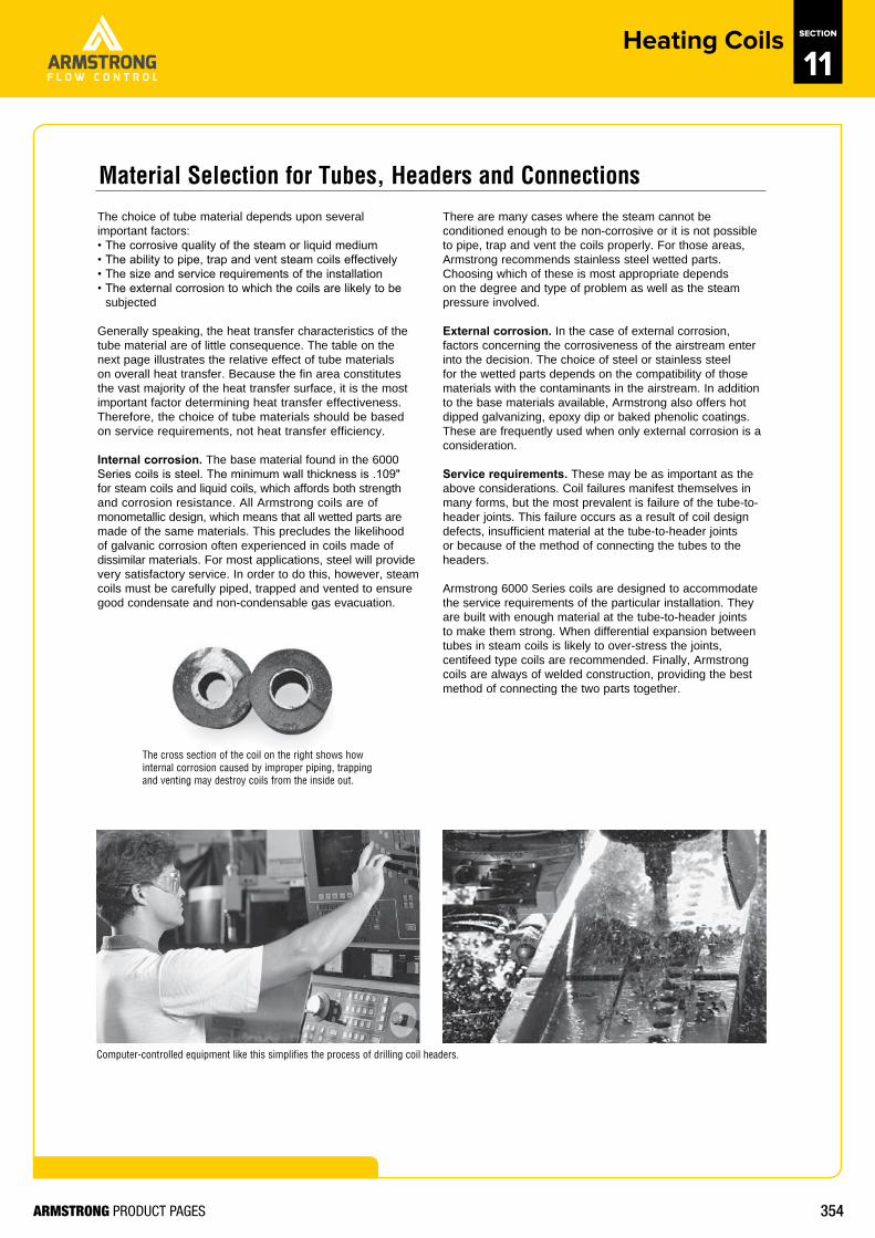
Computer-controlled equipment like this simplifies the process of drilling coil headers.
The cross section of the coil on the right shows how internal corrosion caused by improper piping, trapping and venting may destroy coils from the inside out.
Material Selection for Tubes, Headers and Connections
355ARMSTRONG PRODUCT PAGES
http://armstrongflow.com.au/downloads/1082
Heating Coils SECTION
11H
eating and Cooling Coils
339North America • Latin America • India • Europe / Middle East / Africa • China • Pacifi c Rim
armstronginternational.com
Designs, materials, weights and performance ratings are approximate and subject to change without notice. Visit www.armstronginternational.com for up-to-date information.
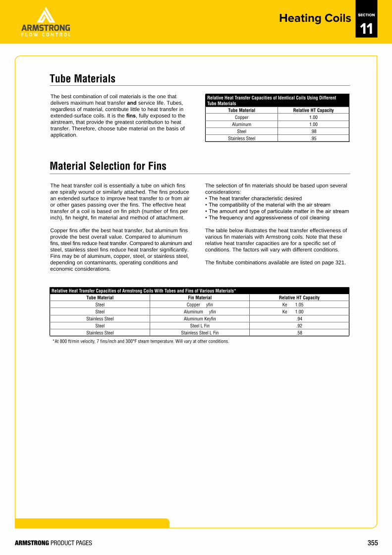
The best combination of coil materials is the one that delivers maximum heat transfer and service life. Tubes, regardless of material, contribute little to heat transfer in extended-surface coils. It is the fins, fully exposed to the airstream, that provide the greatest contribution to heat transfer. Therefore, choose tube material on the basis of application.
Material Selection for Fins
The heat transfer coil is essentially a tube on which fins are spirally wound or similarly attached. The fins produce an extended surface to improve heat transfer to or from air or other gases passing over the fins. The effective heat transfer of a coil is based on fin pitch (number of fins per inch), fin height, fin material and method of attachment.
Copper fins offer the best heat transfer, but aluminum fins provide the best overall value. Compared to aluminum fins, steel fins reduce heat transfer. Compared to aluminum and steel, stainless steel fins reduce heat transfer significantly. Fins may be of aluminum, copper, steel, or stainless steel, depending on contaminants, operating conditions and economic considerations.
The selection of fin materials should be based upon several considerations:• The heat transfer characteristic desired• The compatibility of the material with the air stream• The amount and type of particulate matter in the air stream• The frequency and aggressiveness of coil cleaning
The table below illustrates the heat transfer effectiveness of various fin materials with Armstrong coils. Note that these relative heat transfer capacities are for a specific set of conditions. The factors will vary with different conditions.
The fin/tube combinations available are listed on page 321.
Tube Materials
Relative Heat Transfer Capacities of Identical Coils Using Different Tube Materials
Tube Material Relative HT CapacityCopper 1.00
Aluminum 1.00Steel .98
Stainless Steel .95
Relative Heat Transfer Capacities of Armstrong Coils With Tubes and Fins of Various Materials*Tube Material Fin Material Relative HT Capacity
Steel Copper Keyfin 1.05Steel Aluminum Keyfin 1.00
Stainless Steel Aluminum Keyfin .94Steel Steel L Fin .92
Stainless Steel Stainless Steel L Fin .58
*At 800 ft/min velocity, 7 fins/inch and 300°F steam temperature. Will vary at other conditions.

356ARMSTRONG PRODUCT PAGES
http://armstrongflow.com.au/downloads/1082
Heating Coils SECTION
11H
eatin
g an
d Co
olin
g Co
ils
340North America • Latin America • India • Europe / Middle East / Africa • China • Pacifi c Rim
armstronginternational.com
Designs, materials, weights and performance ratings are approximate and subject to change without notice. Visit www.armstronginternational.com for up-to-date information.
KeyfinThe keyfin is the standard design for Armstrong’s most popular coils. Keyfin coils are manufactured by forming a helical groove in the tube surface, winding the fin into the groove and peening the displaced metal from the groove against the fin. This means a tight fit between the fin and the tube, providing for efficient operation over wide temperature ranges. Keyfin is the superior design for dissimilar fin and tube materials.
L FinThe L fin has a “foot” at its base and is tension wound on knurled tube material. The L-shaped base provides a large contact area between the tube and the fin, ensuring effective, long-lasting heat transfer. The L fin is recommended when tubes and fins are of the same material.
Overlap L FinThe overlap L fin is simply an L fin with an extended base. Each fin overlaps the foot of the previous fin, completely covering the tube surface. The overlap technique makes it possible to create a completely aluminumized coil for applications where exposed steel would be vulnerable to corrosion.
Tube Wall
Fin Compression:AI (CTE) > ST. CTEFin compression is proportional to the temperature.
Fin
Fin Types
357ARMSTRONG PRODUCT PAGES
http://armstrongflow.com.au/downloads/1082
Heating Coils SECTION
11H
eating and Cooling Coils
341North America • Latin America • India • Europe / Middle East / Africa • China • Pacifi c Rim
armstronginternational.com
Designs, materials, weights and performance ratings are approximate and subject to change without notice. Visit www.armstronginternational.com for up-to-date information.
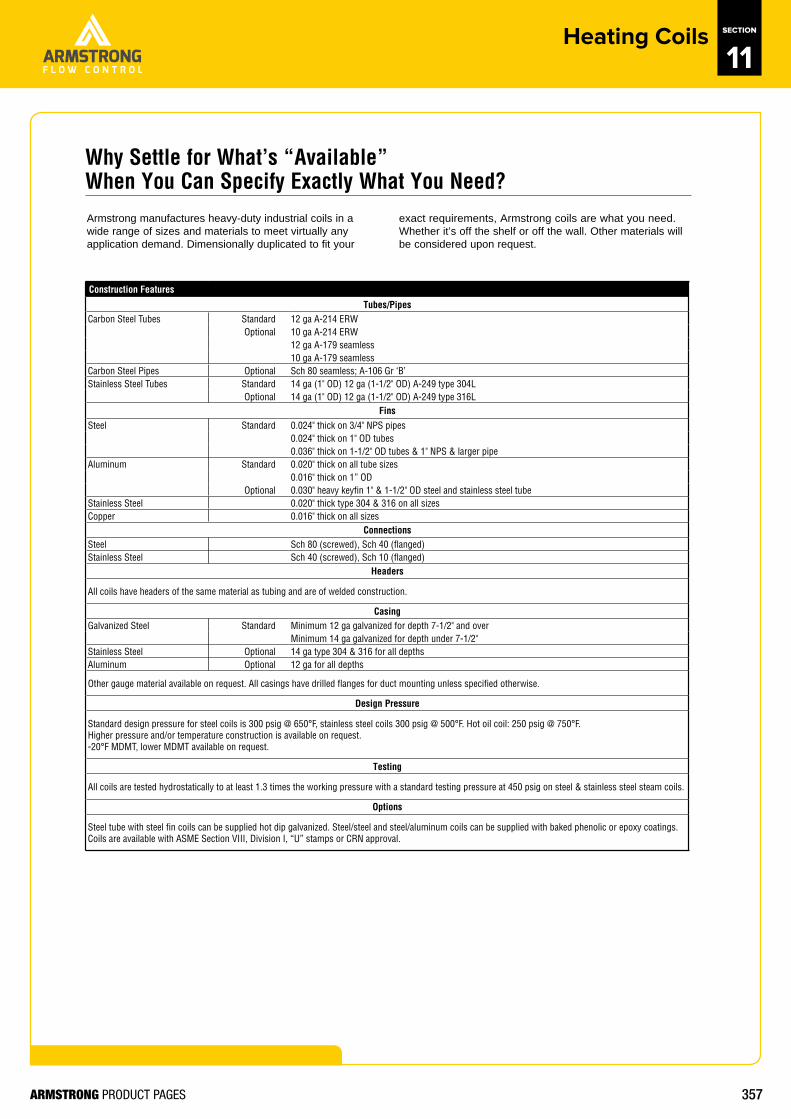
Armstrong manufactures heavy-duty industrial coils in a wide range of sizes and materials to meet virtually any application demand. Dimensionally duplicated to fit your
exact requirements, Armstrong coils are what you need. Whether it’s off the shelf or off the wall. Other materials will be considered upon request.
Why Settle for What’s “Available” When You Can Specify Exactly What You Need?
Construction Features
Tubes/PipesCarbon Steel Tubes Standard 12 ga A-214 ERW
Optional 10 ga A-214 ERW12 ga A-179 seamless10 ga A-179 seamless
Carbon Steel Pipes Optional Sch 80 seamless; A-106 Gr ‘B’Stainless Steel Tubes Standard 14 ga (1" OD) 12 ga (1-1/2" OD) A-249 type 304L
Optional 14 ga (1" OD) 12 ga (1-1/2" OD) A-249 type 316LFins
Steel Standard 0.024" thick on 3/4" NPS pipes0.024" thick on 1" OD tubes0.036" thick on 1-1/2" OD tubes & 1" NPS & larger pipe
Aluminum Standard 0.020" thick on all tube sizes0.016" thick on 1” OD
Optional 0.030" heavy keyfin 1" & 1-1/2" OD steel and stainless steel tubeStainless Steel 0.020" thick type 304 & 316 on all sizesCopper 0.016" thick on all sizes
ConnectionsSteel Sch 80 (screwed), Sch 40 (flanged)Stainless Steel Sch 40 (screwed), Sch 10 (flanged)
Headers
All coils have headers of the same material as tubing and are of welded construction.
CasingGalvanized Steel Standard Minimum 12 ga galvanized for depth 7-1/2" and over
Minimum 14 ga galvanized for depth under 7-1/2"Stainless Steel Optional 14 ga type 304 & 316 for all depthsAluminum Optional 12 ga for all depths
Other gauge material available on request. All casings have drilled flanges for duct mounting unless specified otherwise.
Design Pressure
Standard design pressure for steel coils is 300 psig @ 650°F, stainless steel coils 300 psig @ 500°F. Hot oil coil: 250 psig @ 750°F. Higher pressure and/or temperature construction is available on request. -20°F MDMT, lower MDMT available on request.
Testing
All coils are tested hydrostatically to at least 1.3 times the working pressure with a standard testing pressure at 450 psig on steel & stainless steel steam coils.
Options
Steel tube with steel fin coils can be supplied hot dip galvanized. Steel/steel and steel/aluminum coils can be supplied with baked phenolic or epoxy coatings. Coils are available with ASME Section VIII, Division I, “U” stamps or CRN approval.
358ARMSTRONG PRODUCT PAGES
http://armstrongflow.com.au/downloads/1082
Heating Coils SECTION
11H
eatin
g an
d Co
olin
g Co
ils
342North America • Latin America • India • Europe / Middle East / Africa • China • Pacifi c Rim
armstronginternational.com
Designs, materials, weights and performance ratings are approximate and subject to change without notice. Visit www.armstronginternational.com for up-to-date information.
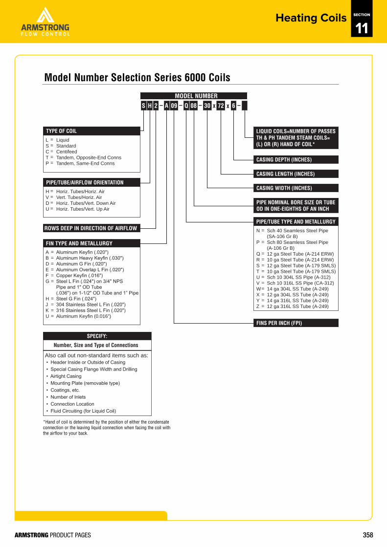
FIN TYPE AND METALLURGY
Aluminum Keyfin (.020")Aluminum Heavy Keyfin (.030")Aluminum G Fin (.020")Aluminum Overlap L Fin (.020")Copper Keyfin (.016")Steel L Fin (.024") on 3/4" NPSPipe and 1" OD Tube(.036") on 1-1/2" OD Tube and 1” PipeSteel G Fin (.024")304 Stainless Steel L Fin (.020")316 Stainless Steel L Fin (.020")Aluminum Keyfin (0.016”)
ABDEFG
HJKU
H
MODEL NUMBER––
LIQUID COILS=NUMBER OF PASSESTH & PH TANDEM STEAM COILS= (L) OR (R) HAND OF COIL*
S 2 30
Sch 40 Seamless Steel Pipe(SA-106 Gr B)Sch 80 Seamless Steel Pipe(A-106 Gr B)12 ga Steel Tube (A-214 ERW)10 ga Steel Tube (A-214 ERW)12 ga Steel Tube (A-179 SMLS)10 ga Steel Tube (A-179 SMLS)Sch 10 304L SS Pipe (A-312)Sch 10 316L SS Pipe (CA-312)14 ga 304L SS Tube (A-249)12 ga 304L SS Tube (A-249)14 ga 316L SS Tube (A-249)12 ga 316L SS Tube (A-249)
N
P
QRSTUVWXYZ
PIPE/TUBE TYPE AND METALLURGY
A 09 – Q 08 x 72 6x –
CASING DEPTH (INCHES)
CASING LENGTH (INCHES)
CASING WIDTH (INCHES)
PIPE NOMINAL BORE SIZE OR TUBE OD IN ONE-EIGHTHS OF AN INCH
FINS PER INCH (FPI)
LiquidStandardCentifeedTandem, Opposite-End ConnsTandem, Same-End Conns
LSCTP
TYPE OF COIL
Horiz. Tubes/Horiz. AirVert. Tubes/Horiz. AirHoriz. Tubes/Vert. Down AirHoriz. Tubes/Vert. Up Air
HVDU
PIPE/TUBE/AIRFLOW ORIENTATION
ROWS DEEP IN DIRECTION OF AIRFLOW
SPECIFY:
• Header Inside or Outside of Casing• Special Casing Flange Width and Drilling• Airtight Casing• Mounting Plate (removable type)• Coatings, etc.• Number of Inlets• Connection Location• Fluid Circuiting (for Liquid Coil)
Number, Size and Type of Connections
Also call out non-standard items such as:
= = = = =
= = = =
= = = = = =
= = = =
=
=
= = = = = = = = = =
*Hand of coil is determined by the position of either the condensateconnection or the leaving liquid connection when facing the coil with the airflow to your back.
Model Number Selection Series 6000 Coils
359ARMSTRONG PRODUCT PAGES
http://armstrongflow.com.au/downloads/1082
Heating Coils SECTION
11
370North America • Latin America • India • Europe / Middle East / Africa • China • Pacifi c Rim
armstronginternational.com
Hea
ting
and
Cool
ing
Coils
Designs, materials, weights and performance ratings are approximate and subject to change without notice. Visit www.armstronginternational.com for up-to-date information.
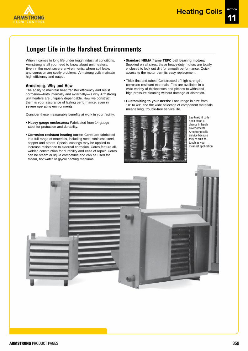
When it comes to long life under tough industrial conditions, Armstrong is all you need to know about unit heaters. Even in the most severe environments, where coil leaks and corrosion are costly problems, Armstrong coils maintain high efficiency and output.
Armstrong: Why and HowThe ability to maintain heat transfer efficiency and resist corrosion—both internally and externally—is why Armstrong unit heaters are uniquely dependable. How we construct them is your assurance of lasting performance, even in severe operating environments.
Consider these measurable benefits at work in your facility:
• Heavy gauge enclosures: Fabricated from 14-gaugesteel for protection and durability.
• Corrosion-resistant heating cores: Cores are fabricatedin a full range of materials, including steel, stainless steel,copper and others. Special coatings may be applied toincrease resistance to external corrosion. Cores feature all-welded construction for durability and ease of repair. Corescan be steam or liquid compatible and can be used forsteam, hot water or glycol heating mediums.
• Standard NEMA frame TEFC ball bearing motors:Supplied on all sizes, these heavy-duty motors are totallyenclosed to lock out dirt for smooth performance. Quickaccess to the motor permits easy replacement.
• Thick fins and tubes: Constructed of high-strength,corrosion-resistant materials. Fins are available in awide variety of thicknesses and pitches to withstandhigh pressure cleaning without damage or distortion.
• Customizing to your needs: Fans range in size from10" to 48", and the wide selection of component materialsmeans long, trouble-free service life.
Lightweight coils don’t stand a chance in harsh environments. Armstrong coils survive because they’re built as tough as your meanest application.
Longer Life in the Harshest Environments
360ARMSTRONG PRODUCT PAGES
http://armstrongflow.com.au/downloads/1082
Heating Coils SECTION
11
371North America • Latin America • India • Europe / Middle East / Africa • China • Pacifi c Rim
armstronginternational.com
Heating and Cooling Coils
Designs, materials, weights and performance ratings are approximate and subject to change without notice. Visit www.armstronginternational.com for up-to-date information.
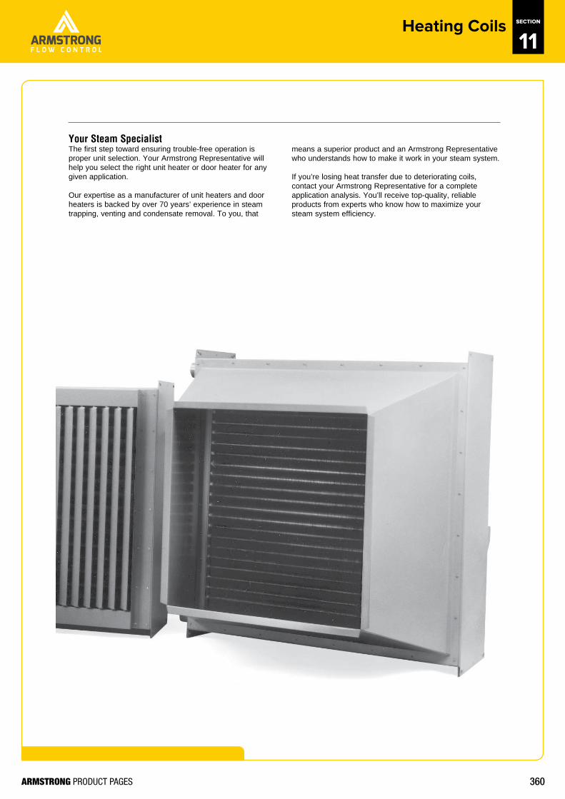
Your Steam Specialist The first step toward ensuring trouble-free operation is proper unit selection. Your Armstrong Representative will help you select the right unit heater or door heater for any given application.
Our expertise as a manufacturer of unit heaters and door heaters is backed by over 70 years’ experience in steam trapping, venting and condensate removal. To you, that
means a superior product and an Armstrong Representative who understands how to make it work in your steam system.
If you’re losing heat transfer due to deteriorating coils, contact your Armstrong Representative for a complete application analysis. You’ll receive top-quality, reliable products from experts who know how to maximize your steam system efficiency.
361ARMSTRONG PRODUCT PAGES
http://armstrongflow.com.au/downloads/1082
Heating Coils SECTION
11
372North America • Latin America • India • Europe / Middle East / Africa • China • Pacifi c Rim
armstronginternational.com
Hea
ting
and
Cool
ing
Coils
Designs, materials, weights and performance ratings are approximate and subject to change without notice. Visit www.armstronginternational.com for up-to-date information.
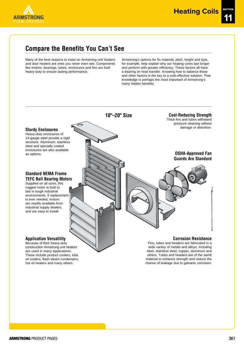
10"–20" Size
OSHA-Approved Fan Guards Are Standard
Many of the best reasons to insist on Armstrong unit heaters and door heaters are ones you never even see. Componentslike motors, bearings, tubes, enclosures and fins are built heavy-duty to ensure lasting performance.
Armstrong’s options for fin material, pitch, height and type, for example, help explain why our heating cores last longer and perform with greater efficiency. These factors all have a bearing on heat transfer. Knowing how to balance these and other factors is the key to a cost-effective solution. That knowledge is perhaps the most important of Armstrong’s many hidden benefits.
Sturdy EnclosuresHeavy-duty enclosures of 14-gauge steel provide a rigid structure. Aluminum, stainless steel and specially coated enclosures are also available as options.
Standard NEMA Frame TEFC Ball Bearing MotorsSupplied on all sizes, this rugged motor is built to last in tough industrial environments. If replacement is ever needed, motors are readily available from industrial supply dealers, and are easy to install.
Application VersatilityBecause of their heavy-duty construction Armstrong unit heaters are used in many applications. These include product coolers, lube oil coolers, flash steam condensers, hot oil heaters and many others.
Corrosion ResistanceFins, tubes and headers are fabricated in a wide variety of metals and alloys, including
steel, stainless steel, copper, aluminum and others. Tubes and headers are of the same
material to enhance strength and reduce the chance of leakage due to galvanic corrosion.
Cost-Reducing StrengthThick fins and tubes withstand
pressure cleaning without damage or distortion.
Compare the Benefits You Can’t See
362ARMSTRONG PRODUCT PAGES
http://armstrongflow.com.au/downloads/1082
Heating Coils SECTION
11
373North America • Latin America • India • Europe / Middle East / Africa • China • Pacifi c Rim
armstronginternational.com
Heating and Cooling Coils
Designs, materials, weights and performance ratings are approximate and subject to change without notice. Visit www.armstronginternational.com for up-to-date information.
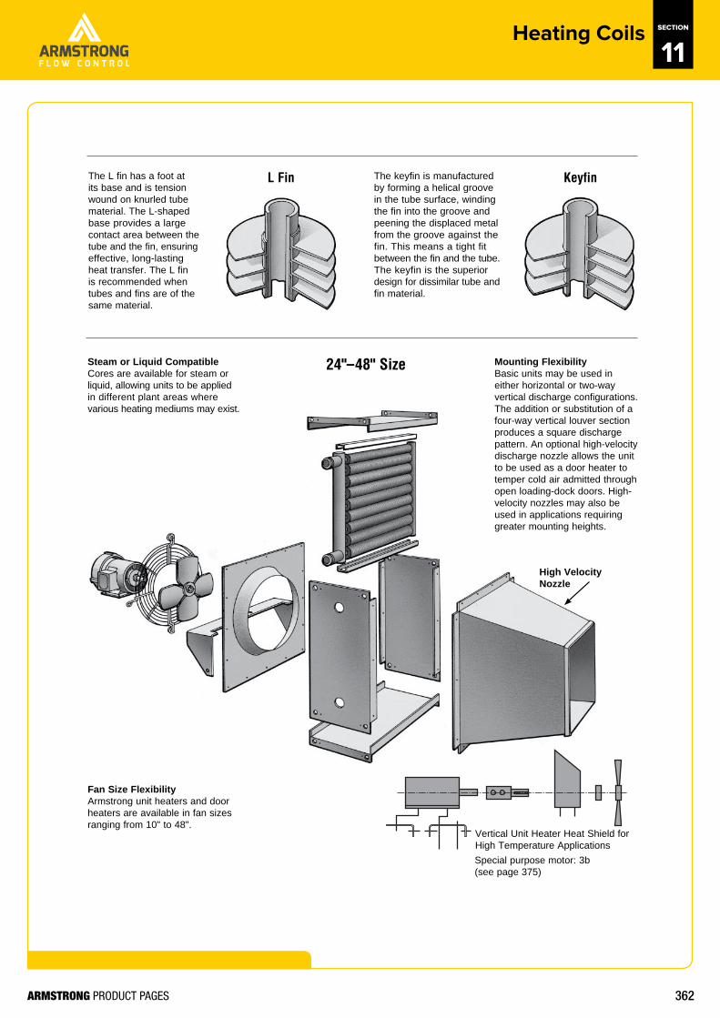
24"–48" Size
L Fin KeyfinThe L fin has a foot at its base and is tension wound on knurled tube material. The L-shaped base provides a largecontact area between the tube and the fin, ensuringeffective, long-lasting heat transfer. The L fin is recommended when tubes and fins are of the same material.
The keyfin is manufactured by forming a helical groove in the tube surface, winding the fin into the groove and peening the displaced metal from the groove against the fin. This means a tight fit between the fin and the tube. The keyfin is the superiordesign for dissimilar tube and fin material.
Steam or Liquid CompatibleCores are available for steam or liquid, allowing units to be applied in different plant areas where various heating mediums may exist.
Fan Size FlexibilityArmstrong unit heaters and door heaters are available in fan sizes ranging from 10" to 48".
Mounting Flexibility Basic units may be used in either horizontal or two-way vertical discharge configurations. The addition or substitution of a four-way vertical louver section produces a square discharge pattern. An optional high-velocity discharge nozzle allows the unit to be used as a door heater to temper cold air admitted through open loading-dock doors. High-velocity nozzles may also be used in applications requiring greater mounting heights.
Vertical Unit Heater Heat Shield for High Temperature Applications
High Velocity Nozzle
Special purpose motor: 3b (see page 375)
363ARMSTRONG PRODUCT PAGES
http://armstrongflow.com.au/downloads/1082
Heating Coils SECTION
11
374North America • Latin America • India • Europe / Middle East / Africa • China • Pacifi c Rim
armstronginternational.com
Hea
ting
and
Cool
ing
Coils
Designs, materials, weights and performance ratings are approximate and subject to change without notice. Visit www.armstronginternational.com for up-to-date information.
MODEL NUMBER
–––
DISCHARGE TYPE
FIN TYPE
NO. FINS/INCH (SEE NOTE 1)
TUBE MATERIAL
MOTOR ELECTRICALCHARACTERISTICS (SEE NOTE 2)
MOTOR TYPE
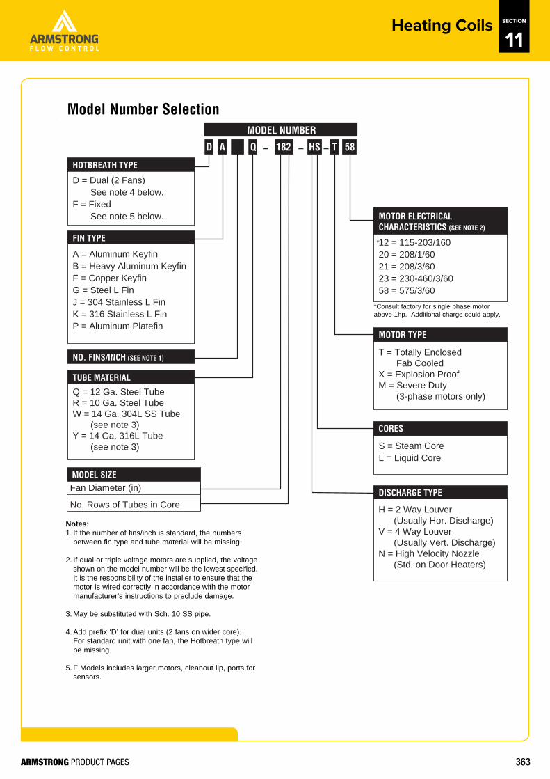
12 = 115-203/16020 = 208/1/6021 = 208/3/6023 = 230-460/3/6058 = 575/3/60
A = Aluminum KeyfinB = Heavy Aluminum KeyfinF = Copper KeyfinG = Steel L FinJ = 304 Stainless L FinK = 316 Stainless L FinP = Aluminum Platefin
T = Totally Enclosed Fab CooledX = Explosion ProofM = Severe Duty (3-phase motors only)Q = 12 Ga. Steel Tube
R = 10 Ga. Steel TubeW = 14 Ga. 304L SS Tube (see note 3)Y = 14 Ga. 316L Tube (see note 3)
H = 2 Way Louver (Usually Hor. Discharge)V = 4 Way Louver (Usually Vert. Discharge)N = High Velocity Nozzle (Std. on Door Heaters)
MODEL SIZE
AD Q 182 T 58HS
CORES
HOTBREATH TYPE
D = Dual (2 Fans) See note 4 below.F = Fixed See note 5 below.
S = Steam CoreL = Liquid Core
Fan Diameter (in)
No. Rows of Tubes in Core
*
Notes:1. If the number of fins/inch is standard, the numbers
between fin type and tube material will be missing.
2. If dual or triple voltage motors are supplied, the voltageshown on the model number will be the lowest specified.It is the responsibility of the installer to ensure that themotor is wired correctly in accordance with the motormanufacturer’s instructions to preclude damage.
3. May be substituted with Sch. 10 SS pipe.
4. Add prefix ‘D’ for dual units (2 fans on wider core).For standard unit with one fan, the Hotbreath type willbe missing.
5. F Models includes larger motors, cleanout lip, ports forsensors.
*Consult factory for single phase motorabove 1hp. Additional charge could apply.
Model Number Selection