hdsd 3112 icr
TRANSCRIPT
USER MANUAL
MODEL: BEN-3112ICR
PANEL FUNCTION
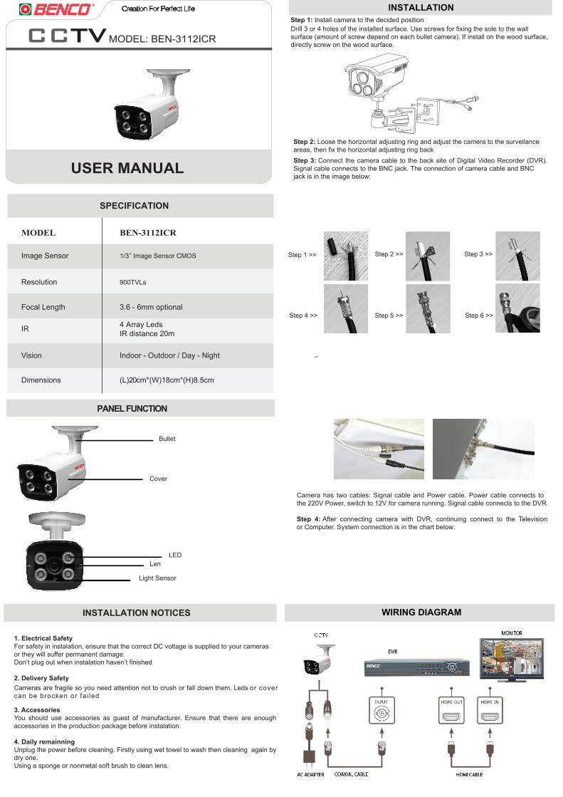
WIRING DIAGRAM
INSTALLATION
Step 1 >>
Step 4 >> Step 5 >> Step 6 >>
Step 2 >> Step 3 >>
3cm
1cm
Step 3: Connect the camera cable to the back site of Digital Video Recorder (DVR). Signal cable connects to the BNC jack. The connection of camera cable and BNC jack is in the image below:
MODEL BEN-3112ICR
SPECIFICATION
Resolution 900TVLs
Focal Length
IR
Vision
Dimensions
Indoor - Outdoor / Day - Night
4 Array LedsIR distance 20m
Image Sensor
3.6 - 6mm optional
1/3’’ Image Sensor CMOS
(L)20cm*(W)18cm*(H)8.5cm
INSTALLATION NOTICES
1. Electrical SafetyFor safety in instalation, ensure that the correct DC voltage is supplied to your camerasor they will suffer permanent damage.Don’t plug out when instalation haven’t finished
2. Delivery Safety
3. AccessoriesYou should use accessories as guest of manufacturer. Ensure that there are enough accessories in the production package before instalation.
4. Daily remainningUnplug the power before cleaning. Firstly using wet towel to wash then cleaning again by dry one.Using a sponge or nonmetal soft brush to clean lens.
Step 1: Install camera to the decided position Drill 3 or 4 holes of the installed surface. Use screws for fixing the sole to the wall surface (amount of screw depend on each bullet camera). If install on the wood surface, directly screw on the wood surface.
Step 2: Loose the horizontal adjusting ring and adjust the camera to the surveilance areas, then fix the horizontal adjusting ring back
Camera has two cables: Signal cable and Power cable. Power cable connects to the 220V Power, switch to 12V for camera running. Signal cable connects to the DVR.
Step 4: After connecting camera with DVR, continuing connect to the Television or Computer. System connection is in the chart below:
Cover
Bullet
LEDLen
Light Sensor
Cameras are fragile so you need attention not to crush or fall down them. Leds or cover can be brocken or fai led
HƯỚNG DẪN SỬ DỤNG
MODEL: BEN-3112ICR
MODEL BEN-3112ICR
THÔNG SỐ KỸ THUẬT
PHÂN TÍCH CẤU TẠO
Độ phân giải 900TVLs
Ống kính
Hồng ngoại
Quan sát
Kích thước
Trong nhà - Ngoài trời/ Ngày - Đêm
4 LED ArrayTầm quan sát ban đêm 20m
Cảm biến hình ảnh
3.6 - 6mm tùy chỉnh
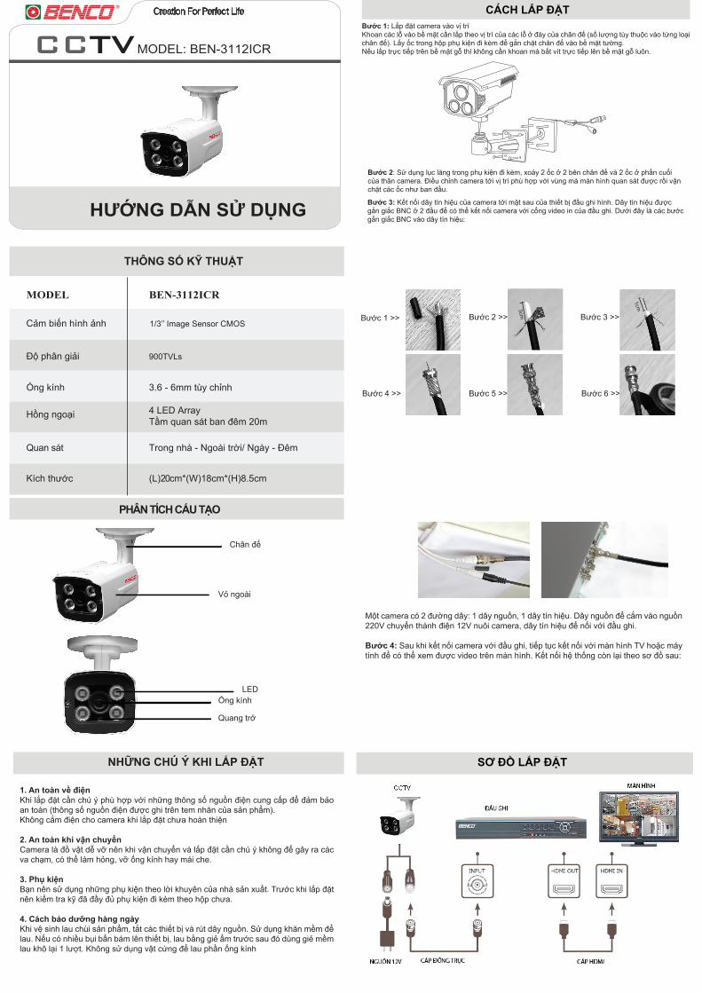
NHỮNG CHÚ Ý KHI LẮP ĐẶT SƠ ĐỒ LẮP ĐẶT
CÁCH LẮP ĐẶT
Bước 1 >>
Bước 4 >> Bước 5 >> Bước 6 >>
Bước 2 >> Bước 3 >>
1. An toàn về điệnKhi lắp đặt cần chú ý phù hợp với những thông số nguồn điện cung cấp để đảm bảo an toàn (thông số nguồn điện được ghi trên tem nhãn của sản phẩm). Không cắm điện cho camera khi lắp đặt chưa hoàn thiện
2. An toàn khi vận chuyểnCamera là đồ vật dễ vỡ nên khi vận chuyển và lắp đặt cần chú ý không để gây ra các va chạm, có thể làm hỏng, vỡ ống kính hay mái che.
3. Phụ kiệnBạn nên sử dụng những phụ kiện theo lời khuyên của nhà sản xuất. Trước khi lắp đặt nên kiểm tra kỹ đã đầy đủ phụ kiện đi kèm theo hộp chưa.
4. Cách bảo dưỡng hàng ngàyKhi vệ sinh lau chùi sản phẩm, tắt các thiết bị và rút dây nguồn. Sử dụng khăn mềm để lau. Nếu có nhiều bụi bẩn bám lên thiết bị, lau bằng giẻ ẩm trước sau đó dùng giẻ mềm lau khô lại 1 lượt. Không sử dụng vật cứng để lau phần ống kính
Bước 1: Lắp đặt camera vào vị trí Khoan các lỗ vào bề mặt cần lắp theo vị trí của các lỗ ở đáy của chân đế (số lượng tùy thuộc vào từng loại chân đế). Lấy ốc trong hộp phụ kiện đi kèm để gắn chặt chân đế vào bề mặt tường.Nếu lắp trực tiếp trên bề mặt gỗ thì không cần khoan mà bắt vít trực tiếp lên bề mặt gỗ luôn.
Bước 2: Sử dụng lục lăng trong phụ kiện đi kèm, xoáy 2 ốc ở 2 bên chân đế và 2 ốc ở phần cuối của thân camera. Điều chỉnh camera tới vị trí phù hợp với vùng mà màn hình quan sát được rồi vặn chặt các ốc như ban đầu.
Một camera có 2 đường dây: 1 dây nguồn, 1 dây tín hiệu. Dây nguồn để cắm vào nguồn 220V chuyển thành điện 12V nuôi camera, dây tín hiệu để nối với đầu ghi.
Bước 4: Sau khi kết nối camera với đầu ghi, tiếp tục kết nối với màn hình TV hoặc máy tính để có thể xem được video trên màn hình. Kết nối hệ thống còn lại theo sơ đồ sau:
3cm
1cm
Bước 3: Kết nối dây tín hiệu của camera tới mặt sau của thiết bị đầu ghi hình. Dây tín hiệu được gắn giắc BNC ở 2 đầu để có thể kết nối camera với cổng video in của đầu ghi. Dưới đây là các bước gắn giắc BNC vào dây tín hiệu:
(L)20cm*(W)18cm*(H)8.5cm
Vỏ ngoài
Chân đế
LEDỐng kính
Quang trở
1/3’’ Image Sensor CMOS