hds super m eco hds super mx eco hds 655 m eco hds … · hds super m eco hds super mx eco ... 22...
TRANSCRIPT

www.kaercher.com 5.961-306 A2008544 05/04
HDS Super M Eco HDS Super MX EcoHDS 655 M EcoHDS 695 M Eco HDS 695 MX EcoHDS 895 M Eco HDS 895 MX EcoHDS 1195 S Eco HDS 1195 SX Eco

2
Deutsch
English
Français
Italiano
Nederlands
Español
Português
ÅëëÞíéêÜÅëëÞíéêÜÅëëÞíéêÜÅëëÞíéêÜ
Dansk
Norsk
Svenska
Suomi
Magyar
Česky
Slovensko
Polska
Româneşte
Türkçe
Русский
Slovensky
Hrvatski
Srpski
Български
41
7
24
59
77
94
147
111
128
164
181
198
247
214
231
264
282
300
353
317
337
370
387

-
1
2
3
4
5
6a
6b
7
8
9
10
11a
11b
12
13
14
15
16
17
18
19
English Operating Instructions
24
Contents
Environmental protection 24
Unit illustration 25
Operating controls 25
Reference to operatinginstructions 26
Commissioning 26
Operation 28
After every operation 31
Decommissioning 32
Maintenance 32
Maintenance tasks 32
Faults 33
Warranty 35
General notes 36
EC conformity declaration 37
Technical data 38
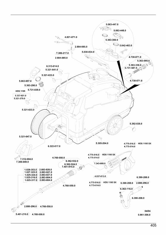
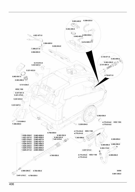
Parts list 405
Danger: Steam!Danger of scalding! Steam escapes here.
Warning!Prior to initial operation it is mandatory toread the operating instructions and thenotes on safety no. 5.951-949!
Inform retailer immediately of anytransportation damage.
Environmental protectionPlease dispose of packagingenvironmentally responsibly
The packaging materials are recyclable.Please do not throw the packaging in withhousehold rubbish but take it to a recyclingcentre.
Please dispose of scrapped unitsenvironmentally-responsibly
Scrapped units consist of valuablerecyclable materials that should be taken toa recycling centre. Batteries, oil and similarproducts must not be allowed tocontaminate the environment. Therefore,please dispose of scrapped units viaappropriate disposal systems.
Please ensure engine oil, fuel oil, dieseland petrolto contaminate the environment. Pleaseprotect the ground and dispose of used oilecologically.
Operating Instructions English
25
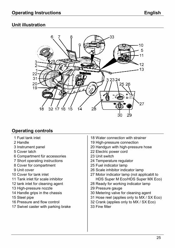
Unit illustration
Operating controls 1 Fuel tank inlet 2 Handle 3 Instrument panel 5 Cover latch 6 Compartment für accessories 7 Short operating instructions 8 Cover for compartment 9 Unit cover10 Cover for tank inlet11 Tank inlet für scale inhibitor12 tank inlet for cleaning agent13 High-pressure nozzle14 Handle grips in the chassis15 Steel pipe16 Pressure and flow control17 Swivel caster with parking brake
18 Water connection with strainer19 High-pressure connection20 Handgun with high-pressure hose22 Electric power cord23 Unit switch24 Temperature regulator25 Fuel indicator lamp26 Scale inhibitor indicator lamp27 Motor indicator lamp (not applicablt to HDS Super M Eco/HDS Super MX Eco)28 Ready for working indicator lamp29 Pressure gauge30 Metering valve for cleaning agent31 Hose reel (applies only to MX / SX Eco)32 Crank (applies only to MX / SX Eco)33 Fine filter
English Operating Instructions
26
Reference to operatinginstructions
All of the item numbers described below inthe operating instructions are referenced inthe illustration of the unit.
Commissioning
Warning!Unit, piping, high-pressure hose andconnections must be in perfect workingorder!! Lock the hand brake.
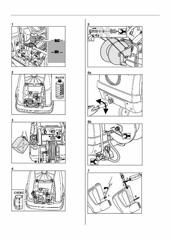
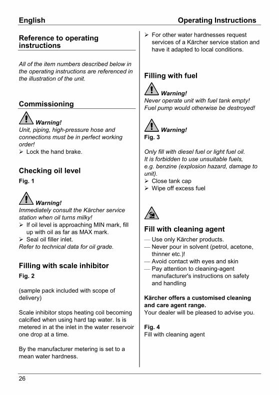
Checking oil levelFig. 1
Warning!Immediately consult the Kärcher servicestation when oil turns milky!! If oil level is approaching MIN mark, fill
up with oil as far as MAX mark.! Seal oil filler inlet.Refer to technical data for oil grade.
Filling with scale inhibitorFig. 2
(sample pack included with scope ofdelivery)
Scale inhibitor stops heating coil becomingcalcified when using hard tap water. Is ismetered in at the inlet in the water reservoirone drop at a time.
By the manufacturer metering is set to amean water hardness.
! For other water hardnesses requestservices of a Kärcher service station andhave it adapted to local conditions.
Filling with fuel
Warning!Never operate unit with fuel tank empty!Fuel pump would otherwise be destroyed!
Warning!Fig. 3
Only fill with diesel fuel or light fuel oil.It is forbidden to use unsuitable fuels,e.g. benzine (explosion hazard, damage tounit).! Close tank cap! Wipe off excess fuel
Fill with cleaning agent— Use only Kärcher products.— Never pour in solvent (petrol, acetone,
thinner etc.)!— Avoid contact with eyes and skin— Pay attention to cleaning-agent
manufacturer's instructions on safetyand handling
Kärcher offers a customised cleaningand care agent range.Your dealer will be pleased to advise you.
Fig. 4Fill with cleaning agent
Operating Instructions English
27
Installing the handgun (unitswithout hose reel)! Connect steel pipe (item 15) with
handgun (item 20)! Insert high-pressure nozzle in union nut! Mount and tighten unit nut! Install the high-pressure hose to high-
pressure connection of unit. (Figure 6a)
Installing the handgun and thehose reel (units with hose reel)! Connect steel pipe (item 15) with
handgun (item 20)! Insert high-pressure nozzle in union nut! Mount and tighten unit nut! Install the hose reel (item31) with the
provided Allen screws, washers andnuts (4 of each). (Figure 5)
! Install the high-pressure hose at thehigh-pressure connection of hose reeland unit. (Figure 6b)
! Connect high-pressure hose of handgunto hose reel
! Wind high-pressure hose onto hose reelwith the smallest possible bends(direction of turns – clockwise -)
Mounting of spare high-pressurehoseFig. 7
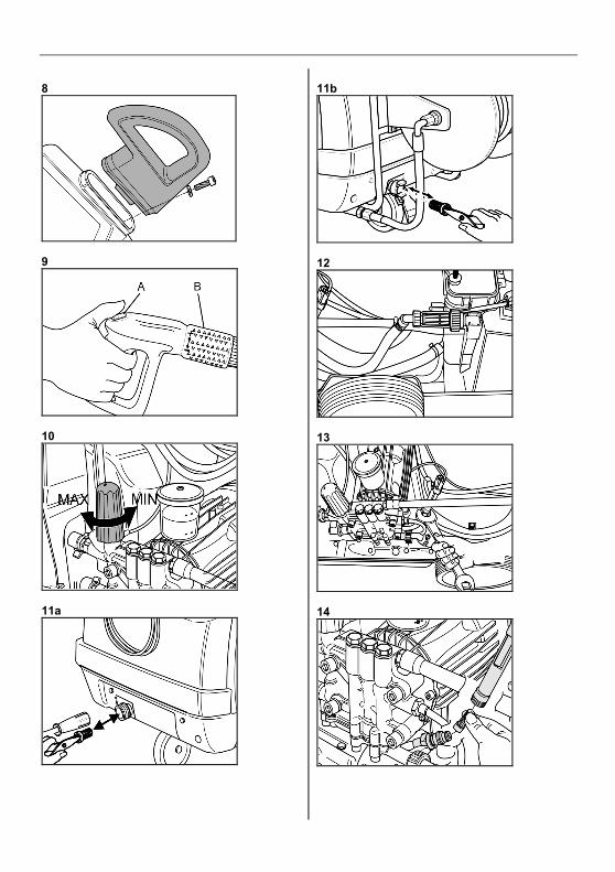
Mounting handleFig. 8
Water connection! See Technical Data for connected loads.! Install supply hose at water connection
(item18) of unit.(supply hose is not part of scope ofdelivery)
Drawing in water from tankWhen you suction water out of an opencontainer you should
! remove water connection at pump head.! screw off the top supply hose with the
fine filter to the water tank and connectto pump head.
! Use a water suction hose with a suctionfilter and a diameter of at least 3/4".
Until the pump sucks up water you should:! Turn the pressure and flow control to
"MAX".! close the metering valve for the cleaning
agent.
Warning!Never suction up water out of a potablewater tank.Never suction up solvent-bearing liquidssuch as paint thinner, benzine, oil orunfiltered water. The seals in the unit arenot resistant to solvents. The mist ofsolvents is highly inflammable, explosiveand poisonous!
English Operating Instructions
28
Mains connectionSee technical data and rating plate forconnected load.
Warning!It is not permissible to exceed themaximum permissible mains impedance atthe electrical terminal (see Technical Data).
Warning!Whenever socket is changed, checkdirection of rotation of motor— If direction of rotation is correct, powerful
jet of air will be felt at exhaust-gasopening of burner.
— If the direction of rotation iswrong: Change the poles at the unitplug. See Fig. 18.
! When an extension cable is used itshould always be complety unwoundand have an adequate cross-section.
Operation
Warning!(Applies only to HDS Super M / MX Eco)Lengthy operation of the unit can lead tovibration-related circulatory disturbances ofthe hands.
A generally valid use duration cannot bespecified, since this is dependent uponseveral influence factors:— Personal predisposition to bad
circulation(frequent suffering from coldfingers, pins and needles in fingers).
— In low ambient temperatures. Wearwarm gloves to keep hands warm.
— Gripping tightly impedes circulation.
— Continuous operation is moredetrimental than operation interrupted bybreaks.
We recommend a medical examination ifthe unit is regularly used for extensive,continuous operation and thecorresponding symptoms (such as, forexample, pins and needles in fingers orcold fingers) are recurrentp.
Switch on the machine! Set unit switch (item 23) to "I"Ready for working indicator lamp (item28)is lit
Warning!The temperature regulator (item 24) mustbe set to "0", since otherwise the burnerpossibly switches on
Unit starts up briefly and is switched off assoon as operating pressure is reached.
Stop the unit immediately when one of theindicator lamps (items 25-27) light upduring operation. Eliminate fault, refer toFaults.
Fig. 9! Release the safety of the handgun (A)Actuation of handgun switches unit back onagain.
Bleed pump if no water emerges from high-pressure nozzle. See problems, "Unit doesnot build up pressure"
Operating Instructions English
29
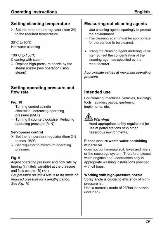
Setting cleaning temperature! Set the remperature regulator (item 24)
to the required temperature
30°C to 90°CHot water cleaning
100°C to 150°CCleaning with steam! Replace high-pressure nozzle by the
steam nozzle (see operation usingsteam)
Setting operating pressure andflow rate
Fig. 10— Turning control spindle
clockwise: Increasing operatingpressure (MAX)
— Turning it counterclockwise: Reducingoperating pressure (MIN)
Servopress control! Set the temperature regulator (item 24)
to max. 98°C.! Set regulator to maximum operating
pressure.
Fig. 9Adjust operating pressure and flow rate byturning (infinitely variable) at the pressureand flow control (B) (+/-)Set pressure on unit if use is to be made ofreduced pressure for a lengthy period.See Fig. 10
Measuring out cleaning agents— Use cleaning agents sparingly to protect
the environment— The cleaning agent must be appropriate
for the surface to be cleaned.
! Using the cleaning agent metering valve(item30) set the concentration of thecleaning agent as specified by themanufacturer
Approximate values at maximum operatingpressure
Intended useFor cleaning: machines, vehicles, buildings,tools, facades, patios, gardeningimplements, etc.
Warning!— Heed appropriate safety regulations for
use at petrol stations or in otherhazardous environments.
Please ensure waste water containingmineral oildoes not contaminate soil, lakes and riversor the sewerage system. Therefore, pleasewash engines and underbodies only inappropriate washing installations providedwith oil traps.
Working with high-pressure nozzleSpray angle is crucial to efficiency of high-pressure jet.Use is normally made of 25°fan jet nozzle(included).
English Operating Instructions
30
Recommended nozzles, available asaccessories— For stubborn dirt
0°full jet nozzle
— For sensitive surfaces and superficialdirt
40°-fan jet nozzle
— For thick-film, stubborn dirt Dirt blaster
— Nozzle with adjustable spray angle,adaptable to many cleaning tasks
Variable-angle nozzle
Cleaning! Set pressure/temperature and detergent
concentration appropriately to surface tobe cleaned
Always start by directing high-pressure jetfrom a good distance at object to becleaned to avoid damage caused byexcessive pressure.
Recommended cleaning methodLoosen up dirt:! Spray on cleaning agent sparingly and
allow to react for 1...5 min (do not allowto dry on).
Remove dirt:! Spray off loosened-up dirt with high-
pressure jet.
Operation with cold waterRemoval of slight contamination and rinsinge.g: gardening implements, patio, tools, etc.
! Set operating pressure as required! Set temperature control (item 24) to "0"
Operation with hot water
Warning!Danger of scalding
! Set the remperature regulator (item 24)to the required temperature
We recommend the following cleaningtemperatures— Slight contamination 30-50°C— Protein soiling, e.g. in foodstuffs industry
max. 60°C— Motor vehicle cleaning, machine
cleaning 60-90°C
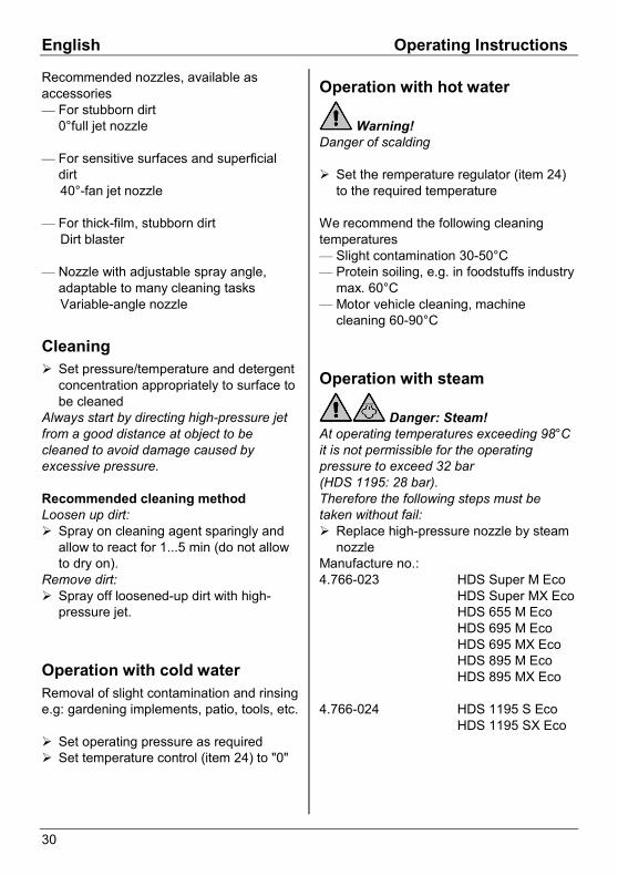
Operation with steam
Danger: Steam!At operating temperatures exceeding 98°Cit is not permissible for the operatingpressure to exceed 32 bar(HDS 1195: 28 bar).Therefore the following steps must betaken without fail:! Replace high-pressure nozzle by steam
nozzleManufacture no.:4.766-023 HDS Super M Eco
HDS Super MX EcoHDS 655 M EcoHDS 695 M EcoHDS 695 MX EcoHDS 895 M EcoHDS 895 MX Eco
4.766-024 HDS 1195 S EcoHDS 1195 SX Eco
Operating Instructions English
31
! Fully open water delivery control at thehandgun, in the + direction to the stop.See Figure 9 (B)
! Set operating pressure to minimumvalue. See Fig. 10
! Set the temperature regulator (item 24)to min. 100°C
Danger: Steam!Danger of scalding!
We recommend the following cleaningtemperatures— Preservative removal, extremely greasy
dirt 100-110°C— Thawing of aggregates, certain facade
cleaning operations up to 140°C
After every operation
Warning!Danger of scalding with hot water.After operating it with hot water or steamthe unit must be cooled for at least twominutes by operating it with cold water andits open handgun.
Following operation with cleaning agent! Set cleaning agent metering valve
(item 30) to "0"! Set unit switch (item 23) to "I"! Actuate handgun and flush unit for
approx. 1 min
Stopping machine! Set unit switch (item 23) to "0"! Shut off water supply! Switch the pump briefly on with the unit
switch (item 23) (approx. 5 sec.)! Remove mains plug from socket ONLY
with dry hands! Remove water connection! Actuate handgun to depressurise unit! Put on safety of handgun Figure 9 (A)! Engage spray lance in cover holder! Reel up the high-pressure hose and
electric cables and attach them tofastenings
Note!Take care not to kink high-pressure hoseand cable!
Note!Frost will destroy unit if water is not drainedoff completely!! Store unit in a frost-free location
Observe the following if the unit isconnected to a flue:Danger of damage caused by cold airentering through the flue. Disconnect unitfrom flue at outside temperatures below0°C.
Immobilise unit if frost-proof storage is notpossible.
English Operating Instructions
32
Decommissioning
In the event of lengthy periods of non-useor if frost-free storage is not possible:! Drain off water and flush out equipment
with antifreeze! Drain cleaning fluid tank
Drain off water! Unscrew water supply hose and high-
pressure hose! Screw off supply line at boiler base and
completely drain heating coil! Run unit for max. 1 min until pump and
lines are empty
Flushing unit with anti-freeze! Fill the float tank with a commercially
available antifreezing compound! Swith the unit on (without the burner)
until it is thoroughly purged! Observe handling instructions of
antifreeze manufacturerBy this means, a certain degree ofcorrosion protection is achieved
Maintenance
Warning!Disconnect unit from mains before carryingout any maintenance or repair work.Always use genuine spare parts
Turn off unit prior to all work, see "Afterevery operation".
! Set unit switch (item 23) to "0"! Pull power plug out of socket! Shut off water supply! Actuate handgun to depressurise unit.! Remove water connection! Allow unit to cool down
Your Kärcher dealer will be pleased toinform you on the performance ofregular safety inspectionsand conclusion of a maintenancecontract
Maintenance intervals
Once a week— Clean strainer in water connection— Clean the fine filter— Check oil levelImmediately consult the Kärcher servicestation when oil turns milky!
Once a month— Clean strainer in low water protection— Clean filter at cleaning-agent suction
hose
After 500 hours of operation, at leastonce a year— Change oil
Maintenance tasks
Clean strainer in waterconnectionFig. 11! Remove strainer! Clean in water and re-insert
Clean the fine filterFig. 12! Cut pressure to unit! Screw off cover with filter! Clean filter with clean water or with
compressed air! Assemble in the reverse order
Operating Instructions English
33
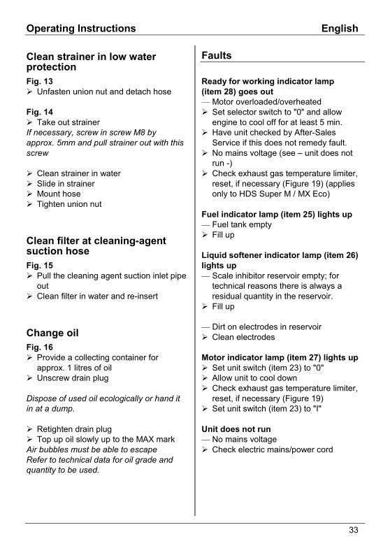
Clean strainer in low waterprotectionFig. 13! Unfasten union nut and detach hose
Fig. 14! Take out strainerIf necessary, screw in screw M8 byapprox. 5mm and pull strainer out with thisscrew
! Clean strainer in water! Slide in strainer! Mount hose! Tighten union nut
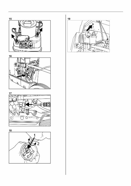
Clean filter at cleaning-agentsuction hoseFig. 15! Pull the cleaning agent suction inlet pipe
out! Clean filter in water and re-insert
Change oilFig. 16! Provide a collecting container for
approx. 1 litres of oil! Unscrew drain plug
Dispose of used oil ecologically or hand itin at a dump.
! Retighten drain plug! Top up oil slowly up to the MAX markAir bubbles must be able to escapeRefer to technical data for oil grade andquantity to be used.
Faults
Ready for working indicator lamp(item 28) goes out— Motor overloaded/overheated! Set selector switch to "0" and allow
engine to cool off for at least 5 min.! Have unit checked by After-Sales
Service if this does not remedy fault.! No mains voltage (see – unit does not
run -)! Check exhaust gas temperature limiter,
reset, if necessary (Figure 19) (appliesonly to HDS Super M / MX Eco)
Fuel indicator lamp (item 25) lights up— Fuel tank empty! Fill up
Liquid softener indicator lamp (item 26)lights up— Scale inhibitor reservoir empty; for
technical reasons there is always aresidual quantity in the reservoir.
! Fill up
— Dirt on electrodes in reservoir! Clean electrodes
Motor indicator lamp (item 27) lights up! Set unit switch (item 23) to "0"! Allow unit to cool down! Check exhaust gas temperature limiter,
reset, if necessary (Figure 19)! Set unit switch (item 23) to "I"
Unit does not run— No mains voltage! Check electric mains/power cord
English Operating Instructions
34
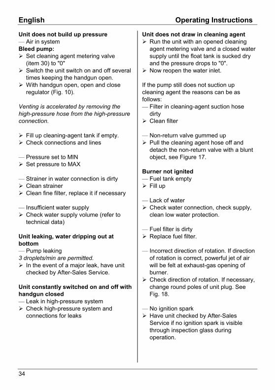
Unit does not build up pressure— Air in systemBleed pump:! Set cleaning agent metering valve
(item 30) to "0"! Switch the unit switch on and off several
times keeping the handgun open.! With handgun open, open and close
regulator (Fig. 10).
Venting is accelerated by removing thehigh-pressure hose from the high-pressureconnection.
! Fill up cleaning-agent tank if empty.! Check connections and lines
— Pressure set to MIN! Set pressure to MAX
— Strainer in water connection is dirty! Clean strainer! Clean fine filter, replace it if necessary
— Insufficient water supply! Check water supply volume (refer to
technical data)
Unit leaking, water dripping out atbottom— Pump leaking3 droplets/min are permitted.! In the event of a major leak, have unit
checked by After-Sales Service.
Unit constantly switched on and off withhandgun closed— Leak in high-pressure system! Check high-pressure system and
connections for leaks
Unit does not draw in cleaning agent! Run the unit with an opened cleaning
agent metering valve and a closed watersupply until the float tank is sucked dryand the pressure drops to "0".
! Now reopen the water inlet.
If the pump still does not suction upcleaning agent the reasons can be asfollows:— Filter in cleaning-agent suction hose
dirty! Clean filter
— Non-return valve gummed up! Pull the cleaning agent hose off and
detach the non-return valve with a bluntobject, see Figure 17.
Burner not ignited— Fuel tank empty! Fill up
— Lack of water! Check water connection, check supply,
clean low water protection.
— Fuel filter is dirty! Replace fuel filter.
— Incorrect direction of rotation. If directionof rotation is correct, powerful jet of airwill be felt at exhaust-gas opening ofburner.
! Check direction of rotation. If necessary,change round poles of unit plug. SeeFig. 18.
— No ignition spark! Have unit checked by After-Sales
Service if no ignition spark is visiblethrough inspection glass duringoperation.
Operating Instructions English
35
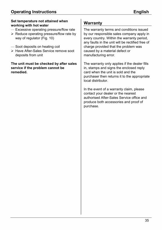
Set temperature not attained whenworking with hot water— Excessive operating pressure/flow rate! Reduce operating pressure/flow rate by
way of regulator (Fig. 10)
— Soot deposits on heating coil! Have After-Sales Service remove soot
deposits from unit
The unit must be checked by after salesservice if the problem cannot beremedied.
WarrantyThe warranty terms and conditions issuedby our responsible sales company apply inevery country. Within the warranty period,any faults in the unit will be rectified free ofcharge provided that the problem wascaused by a material defect ormanufacturing error.
The warranty only applies if the dealer fillsin, stamps and signs the enclosed replycard when the unit is sold and thepurchaser then returns it to the appropriatelocal distributor.
In the event of a warranty claim, pleasecontact your dealer or the nearestauthorised After-Sales Service office andproduce both accessories and proof ofpurchase.
English Operating Instructions
36
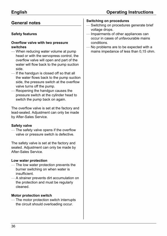
General notes
Safety features
Overflow valve with two pressureswitches— When reducing water volume at pump
head or with the servopress control, theoverflow valve will open and part of thewater will flow back to the pump suctionside.
— If the handgun is closed off so that allthe water flows back to the pump suctionside, the pressure switch at the overflowvalve turns off the pump.
— Reopening the handgun causes thepressure switch at the cylinder head toswitch the pump back on again.
The overflow valve is set at the factory andlead-sealed. Adjustment can only be madeby After-Sales Service.
Safety valve— The safety valve opens if the overflow
valve or pressure switch is defective.
The safety valve is set at the factory andsealed. Adjustment can only be made byAfter-Sales Service.
Low water protection— The low water protection prevents the
burner switching on when water isinsufficient.
— A strainer prevents dirt accumulation onthe protection and must be regularlycleaned.
Motor protection switch— The motor protection switch interrupts
the circuit should overloading occur.
Switching on procedures— Switching on procedures generate brief
voltage drops.— Impairments of other appliances can
occur in cases of unfavourable mainsconditions.
— No problems are to be expected with amains impedance of less than 0,15 ohm.
Operating Instructions English
37
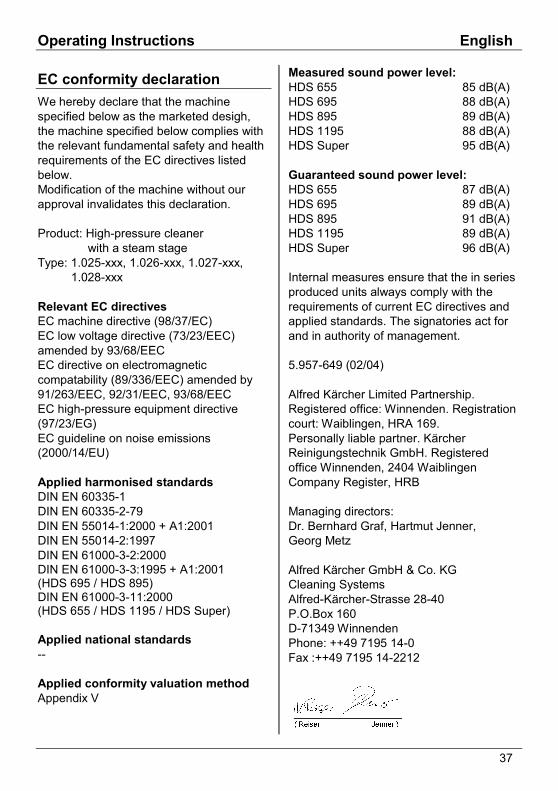
EC conformity declarationWe hereby declare that the machinespecified below as the marketed desigh,the machine specified below complies withthe relevant fundamental safety and healthrequirements of the EC directives listedbelow.Modification of the machine without ourapproval invalidates this declaration.
Product: High-pressure cleaner with a steam stageType: 1.025-xxx, 1.026-xxx, 1.027-xxx, 1.028-xxx
Relevant EC directivesEC machine directive (98/37/EC)EC low voltage directive (73/23/EEC)amended by 93/68/EECEC directive on electromagneticcompatability (89/336/EEC) amended by91/263/EEC, 92/31/EEC, 93/68/EECEC high-pressure equipment directive(97/23/EG)EC guideline on noise emissions(2000/14/EU)
Applied harmonised standardsDIN EN 60335-1DIN EN 60335-2-79DIN EN 55014-1:2000 + A1:2001DIN EN 55014-2:1997DIN EN 61000-3-2:2000DIN EN 61000-3-3:1995 + A1:2001(HDS 695 / HDS 895)DIN EN 61000-3-11:2000(HDS 655 / HDS 1195 / HDS Super)
Applied national standards--
Applied conformity valuation methodAppendix V
Measured sound power level:HDS 655 85 dB(A)HDS 695 88 dB(A)HDS 895 89 dB(A)HDS 1195 88 dB(A)HDS Super 95 dB(A)
Guaranteed sound power level:HDS 655 87 dB(A)HDS 695 89 dB(A)HDS 895 91 dB(A)HDS 1195 89 dB(A)HDS Super 96 dB(A)
Internal measures ensure that the in seriesproduced units always comply with therequirements of current EC directives andapplied standards. The signatories act forand in authority of management.
5.957-649 (02/04)
Alfred Kärcher Limited Partnership.Registered office: Winnenden. Registrationcourt: Waiblingen, HRA 169.Personally liable partner. KärcherReinigungstechnik GmbH. Registeredoffice Winnenden, 2404 WaiblingenCompany Register, HRB
Managing directors:Dr. Bernhard Graf, Hartmut Jenner,Georg Metz
Alfred Kärcher GmbH & Co. KGCleaning SystemsAlfred-Kärcher-Strasse 28-40P.O.Box 160D-71349 WinnendenPhone: ++49 7195 14-0Fax :++49 7195 14-2212
Tech
nica
l Dat
a E
nglis
h
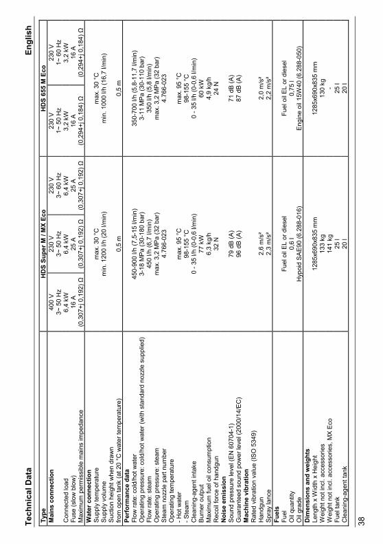
38Type
HD
S Su
per M
/ M
X Ec
oH
DS
655
M E
coM
ains
con
nect
ion
400
V3~
50
Hz
230
V3~
50
Hz
230
V3~
60
Hz
230
V1~
50
Hz
230
V1~
60
Hz
Con
nect
ed lo
ad6,
4 kW
6,4
kW6,
4 kW
3,2
kW3,
2 kW
Fuse
(slo
w b
low
)16
A25
A25
A16
A16
AM
axim
um p
erm
issi
ble
mai
ns im
peda
nce
(0,3
07+j
0,1
92) Ω
(0,3
07+j
0,1
92) Ω
(0,3
07+j
0,1
92) Ω
(0,2
94+j
0,1
84) Ω
(0,2
94+j
0,1
84) Ω
Wat
er c
onne
ctio
nS
uppl
y te
mpe
ratu
rem
ax. 3
0 °C
max
. 30
°CS
uppl
y vo
lum
em
in. 1
200
l/h (2
0 l/m
in)
min
. 100
0 l/h
(16,
7 l/m
in)
Suc
tion
heig
ht w
hen
draw
nfro
m o
pen
tank
(at 2
0 °C
wat
er te
mpe
ratu
re)
0,5
m0,
5 m
Perf
orm
ance
dat
aFl
ow ra
te: c
old/
hot w
ater
450-
900
l/h (7
,5-1
5 l/m
in)
350-
700
l/h (5
,8-1
1,7
l/min
)O
pera
ting
pres
sure
: col
d/ho
t wat
er (w
ith s
tand
ard
nozz
le s
uppl
ied)
3-18
MP
a (3
0-18
0 ba
r)3-
11 M
Pa
(30-
110
bar)
Flow
rate
: ste
am45
0 l/h
(6,7
l/m
in)
350
l/h (5
,8 l/
min
)O
pera
ting
pres
sure
: ste
amm
ax. 3
,2 M
Pa
(32
bar)
max
. 3,2
MP
a (3
2 ba
r)S
team
noz
zle
part
num
ber
4.76
6-02
34.
766-
023
Ope
ratin
g te
mpe
ratu
re- H
ot w
ater
max
. 95
°Cm
ax. 9
5 °C
- Ste
am98
-155
°C
98-1
55 °
CC
lean
ing-
agen
t int
ake
0 - 3
5 l/h
(0-0
,6 l/
min
)0
- 35
l/h (0
-0,6
l/m
in)
Bur
ner o
utpu
t77
kW
60 k
WM
axim
um fu
el o
il co
nsum
ptio
n6,
3 kg
/h4,
9 kg
/hR
ecoi
l for
ce o
f han
dgun
32 N
24 N
Noi
se e
mis
sion
Sou
nd p
ress
ure
leve
l (E
N 6
0704
-1)
79 d
B (A
)71
dB
(A)
Gua
rant
eed
soun
d po
wer
leve
l (20
00/1
4/E
C)
96 d
B (A
)87
dB
(A)
Mac
hine
vib
ratio
nR
ated
vib
ratio
n va
lue
(ISO
534
9)H
andg
un2,
6 m
/s²
2,0
m/s
²S
pray
lanc
e2,
3 m
/s²
2,2
m/s
²Fu
els
Fuel
Fuel
oil
EL
or d
iese
lFu
el o
il E
L or
die
sel
Oil
quan
tity
0,6
l0,
75 l
Oil
grad
eH
ypoi
d S
AE
90 (6
.288
-016
)E
ngin
e oi
l 15W
40 (6
.288
-050
)D
imen
sion
s an
d w
eigh
tsLe
ngth
x W
idth
x H
eigh
t12
85x6
90x8
35 m
m12
85x6
90x8
35 m
mW
eigh
t not
incl
. acc
esso
ries
133
kg13
0 kg
Wei
ght n
ot in
cl. a
cces
sorie
s, M
X E
co14
1 kg
-Fu
el ta
nk25
l25
lC
lean
ing-
agen
t tan
k20
l20
l
Tech
nica
l Dat
a E
nglis
h
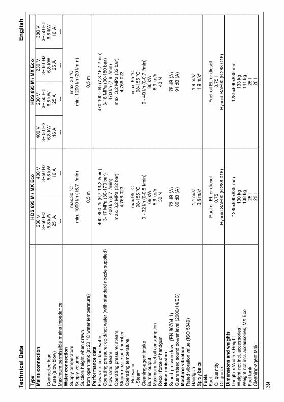
39Type
HD
S 69
5 M
/ M
X Ec
oH
DS
895
M /
MX
Eco
Mai
ns c
onne
ctio
n23
0 V
3~50
Hz
400
V3~
50 H
z40
0 V
3~ 5
0 H
z23
0 V
3~ 5
0 H
z23
0 V
3~ 6
0 H
z38
0 V
3~ 5
0 H
zC
onne
cted
load
5,8
kW5,
8 kW
6,8
kW6,
8 kW
6,8
kW6,
8 kW
Fuse
(slo
w b
low
)M
axim
um p
erm
issi
ble
mai
ns im
peda
nce
25 A ---
16 A ---
16 A ---
25 A ---
25 A ---
16 A ---
Wat
er c
onne
ctio
nS
uppl
y te
mpe
ratu
rem
ax.3
0 °C
max
. 30
°CS
uppl
y vo
lum
em
in. 1
000
l/h (1
6,7
l/min
)m
in. 1
200
l/h (2
0 l/m
in)
Suc
tion
heig
ht w
hen
draw
nfro
m o
pen
tank
(at 2
0 °C
wat
er te
mpe
ratu
re)
0,5
m0,
5 m
Perf
orm
ance
dat
aFl
ow ra
te: c
old/
hot w
ater
400-
800
l/h (6
,7-1
3,3
l/min
)47
0-10
00 l/
h (7
,8-1
6,7
l/min
)O
pera
ting
pres
sure
: col
d/ho
t wat
er (w
ith s
tand
ard
nozz
le s
uppl
ied)
3-17
MP
a (3
0-17
0 ba
r)3-
18 M
Pa
(30-
180
bar)
Flow
rate
: ste
am40
0 l/h
(6,7
l/m
in)
470
l/h (7
,8 l/
min
)O
pera
ting
pres
sure
: ste
amm
ax. 3
,2 M
Pa
(32
bar)
max
. 3,2
MP
a (3
2 ba
r)S
team
noz
zle
part
num
ber
4.76
6-02
34.
766-
023
Ope
ratin
g te
mpe
ratu
re- H
ot w
ater
max
.95
°Cm
ax. 9
5 °C
- Ste
am98
-155
°C
98-1
55 °
CC
lean
ing-
agen
t int
ake
0 - 3
2 l/h
(0-0
,5 l/
min
)0
- 40
l/h (0
-0,7
l/m
in)
Bur
ner o
utpu
t69
kW
86 k
WM
axim
um fu
el o
il co
nsum
ptio
n5,
6 kg
/h6,
9 kg
/hR
ecoi
l for
ce o
f han
dgun
32 N
43 N
Noi
se e
mis
sion
Sou
nd p
ress
ure
leve
l (E
N 6
0704
-1)
73 d
B (A
)75
dB
(A)
Gua
rant
eed
soun
d po
wer
leve
l (20
00/1
4/E
C)
89 d
B (A
)91
dB
(A)
Mac
hine
vib
ratio
nR
ated
vib
ratio
n va
lue
(ISO
534
9)H
andg
unS
pray
lanc
e1,
4 m
/s²
0,8
m/s
²1,
9 m
/s²
1,9
m/s
²Fu
els
Fuel
Fuel
oil
EL
or d
iese
lFu
el o
il E
L or
die
sel
Oil
quan
tity
0,75
l0,
75 l
Oil
grad
eH
ypoi
d SA
E90
(6.2
88-0
16)
Hyp
oid
SAE9
0 (6
.288
-016
)D
imen
sion
s an
d w
eigh
tsLe
ngth
x W
idth
x H
eigh
t12
85x6
90x8
35 m
m12
85x6
90x8
35 m
mW
eigh
t not
incl
. acc
esso
ries
130
kg13
3 kg
Wei
ght n
ot in
cl. a
cces
sorie
s, M
X E
co13
8 kg
141
kgFu
el ta
nk25
l25
lC
lean
ing-
agen
t tan
k20
l20
l
Tech
nica
l Dat
a E
nglis
h
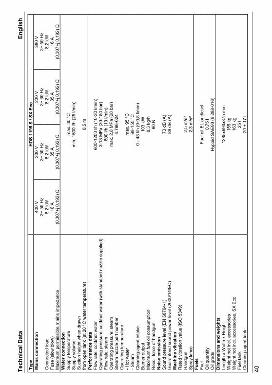
40Type
HD
S 11
95 S
/ SX
Eco
Mai
ns c
onne
ctio
n40
0 V
3~ 5
0 H
z23
0 V
3~ 5
0 H
z23
0 V
3~ 6
0 H
z38
0 V
3~ 5
0 H
zC
onne
cted
load
8,2
kW8,
2 kW
8,2
kW8,
2 kW
Fuse
(slo
w b
low
)M
axim
um p
erm
issi
ble
mai
ns im
peda
nce
16 A
(0,3
07+j
0,1
92) Ω
35 A
(0,3
07+j
0,1
92) Ω
35 A
(0,3
07+j
0,1
92) Ω
16 A
(0,3
07+j
0,1
92) Ω
Wat
er c
onne
ctio
nS
uppl
y te
mpe
ratu
rem
ax. 3
0 °C
Sup
ply
volu
me
min
. 150
0 l/h
(25
l/min
)S
uctio
n he
ight
whe
n dr
awn
from
ope
n ta
nk (a
t 20
°C w
ater
tem
pera
ture
)0,
5 m
Perf
orm
ance
dat
aFl
ow ra
te: c
old/
hot w
ater
600-
1200
l/h
(10-
20 l/
min
)O
pera
ting
pres
sure
: col
d/ho
t wat
er (w
ith s
tand
ard
nozz
le s
uppl
ied)
3-18
MP
a (3
0-18
0 ba
r)Fl
ow ra
te: s
team
600
l/h (1
0 l/m
in)
Ope
ratin
g pr
essu
re: s
team
max
. 2,8
MP
a (2
8 ba
r)S
team
noz
zle
part
num
ber
4.76
6-02
4O
pera
ting
tem
pera
ture
- Hot
wat
erm
ax. 9
5 °C
- Ste
am98
-155
°C
Cle
anin
g-ag
ent i
ntak
e0
- 48
l/h (0
-0,8
l/m
in)
Bur
ner o
utpu
t10
3 kW
Max
imum
fuel
oil
cons
umpt
ion
8,3
kg/h
Rec
oil f
orce
of h
andg
un60
NN
oise
em
issi
onS
ound
pre
ssur
e le
vel (
EN
607
04-1
)73
dB
(A)
Gua
rant
eed
soun
d po
wer
leve
l (20
00/1
4/E
C)
89 d
B (A
)M
achi
ne v
ibra
tion
Rat
ed v
ibra
tion
valu
e (IS
O 5
349)
Han
dgun
2,5
m/s
²S
pray
lanc
e2,
3 m
/s²
Fuel
sFu
elFu
el o
il E
L or
die
sel
Oil
quan
tity
0,75
lO
il gr
ade
Hyp
oid
SA
E90
(6.2
88-0
16)
Dim
ensi
ons
and
wei
ghts
Leng
th x
Wid
th x
Hei
ght
1285
x690
x875
mm
Wei
ght n
ot in
cl. a
cces
sorie
s15
5 kg
Wei
ght n
ot in
cl. a
cces
sorie
s, S
X E
co16
3 kg
Fuel
tank
25 l
Cle
anin
g-ag
ent t
ank
20 +
17
l
405
406