hds 7/12 m, hds 8/18 m, hds 9/18 m, hds 10/20 m, hds 12/18 ... · – hds 13/20-4 s/sx 1 appliance...
TRANSCRIPT
English 5.906-432.0 Rev. 00 (06/15) 1
HDS 7/12 M, HDS 8/18 M,HDS 9/18 M, HDS 10/20 M,HDS 12/18 S, HDS 13/20 SService Manual
2 English 5.906-432.0 Rev. 00 (06/15)
1 Contents
2 Preface 5
3 Safety instructions 5
3.1 Hazard levels 5
4 Technical Features 54.1 General 5
4.2 Connection performance of appliance 5
4.3 Pump 5
4.4 Electronics system 5
4.5 Detergent 5
4.6 Accessories 6
4.7 Field of application 6
4.8 Type plate 6
5 Parts of the system 75.1 Front view 7
5.2 View from the back, (device without hose reel) 8
5.3 View from the back, (device with hose reel) 9
5.4 Operator console 105.4.1 Control panel with LED indicator 105.4.2 Template numerical value display 135.4.3 Control panel, view from the inside 155.4.4 Printed circuit board, control panel 165.4.5 Control panel with display indication (HDS 13/20 only) 17
6 Function 18
6.1 Operating displays 18
6.2 Maintenance operating fluids 18
6.3 Setting liquid softener 19
6.4 SB mode 19
6.5 Storage compartments 20
6.6 Cover 21
6.7 View from the right, cover removed 226.7.1 Revised device design (with filter before the pump and electronic ignition transformer) 23
6.8 Service switch 24
6.9 Fuel tank 25
6.10 Liquid softener 266.10.1 Feed via tank (export variant) 266.10.2 Feed via RFID (Europe variant) 276.10.3 Functionality RFID 29
6.11 Swimmer tank 30
6.12 Detergent Tank 316.12.1 Detergent tank 1 316.12.2 Detergent tank 2 32
6.13 Detergent dosing valve 33
6.14 Motor (air-cooled) 346.14.1 Motor (air-cooled) 35
6.15 Electrical box, air-cooled motor 36
6.16 Engine (water-cooled) 376.16.1 Engine (water-cooled) 386.16.2 Electrical box, water-cooled engine 39
6.17 Pump 406.17.1 Revised version with filter before the pump 41
6.18 Safety block 42
6.19 Safety block (water shortage safeguard old) 436.19.1 Water shortage safeguard as cartridge 44
English 5.906-432.0 Rev. 00 (06/15) 3
6.19.2 Safety block (water shortage safeguard new) 446.19.3 Function water shortage safeguard and dry-run protection 456.19.4 Function of safety valve 45
6.20 Burner blower with fuel pump 46
6.21 Booster heater (with ignition transformer) 48
6.22 Booster heater (with ignition transformer new) 496.22.1 Type plate of heating coil 496.22.2 Ignition transformer 506.22.3 Flame sensor with holder on the burner 506.22.4 Sectional view booster heater 51
6.23 Burner 53
6.24 Burner 54
6.25 Output, booster heater 55
6.26 Hand spraygun 56
6.27 Pressure and volume regulation 57
6.28 Functional diagram of pressure water operation (water-cooled motor) 58
6.29 Functional diagram vacuuming operation 60
6.30 Vacuuming operations 62
6.31 Pressure and volume regulation 636.31.1 Function pressure and volume regulation 64
6.32 Functional description of pressure switch 656.32.1 Appliance is switched off 656.32.2 The appliance is switched on and the gun is open 666.32.3 Gun is closed 676.32.4 The gun is reopened when the appliance is switched on 68
7 Basic settings and service procedures 697.1 Remove the hose drum 69
7.1.1 Uninstall / install high-pressure hose 697.1.2 Renew O-rings axle, hose reel 707.1.3 Uninstall / install pipeline with axle 72
7.2 Uninstall / install pressure gauge 73
7.3 Adjust safety valve 74
7.4 Service functions with LED display 75
7.5 Set up the switching off process 76
7.6 Set up the leakage behaviour 76
7.7 Brightness value of the flame sensor 77
7.8 RFID query 78
7.9 Testing the temperature sensor 78
7.10 Testing the water temperature setting and the programme switch 79
7.11 Testing the service switch 82
7.12 Testing the sensor 83
7.13 Error memory 84
7.14 Operating hours 86
7.15 Gun switching operations since gun service 87
7.16 Gun services 88
7.17 Gun switches since initial startup 90
7.18 Operation duration of the burner since burner service 91
7.19 Burner service 92
7.20 Burner operation since initial startup 94
7.21 Operating hours of the pump since pump service 95
7.22 Pump service 96
7.23 Pump operation since initial startup 98
7.24 Servicefunktionen mit Displayanzeige 99
7.25 Set up the switching off process 100
7.26 Set up the leakage behaviour 100
7.27 RFID query 101
4 English 5.906-432.0 Rev. 00 (06/15)
7.28 Brightness value of the flame sensor 101
7.29 Testing the temperature sensor 101
7.30 Testing the water temperature setting and the programme switch 102
7.31 Test service switch 102
7.32 Testing the sensors 103
7.33 Error memory 104
7.34 Operating hours 106
7.35 Gun switching operations since gun service 106
7.36 Gun services 106
7.37 Gun services since initial startup 106
7.38 Operation duration of the burner since startup 107
7.39 Burner service 107
7.40 Burner operation since initial startup 107
7.41 Operating hours of the pump since pump service 107
7.42 Pump services 108
7.43 Pump operation since initial startup 108
7.44 Quick overview for reading the service functions 109
7.45 Reset of the maintenances 109
7.46 Overview of a quick check of the device status 110
7.47 Settings, burner 111
7.48 Installation air duct on the outer jacket 112
7.49 Adjusting the working pressure with the rotary regulator on the gun 1137.49.1 Setting the maximum working pressure 1137.49.2 Setting the minimum working pressure 114
7.50 Setting the working pressure with standard gun without rotary knob 1157.50.1 Setting the maximum working pressure 1157.50.2 Setting the minimum working pressure 116
8 Care and maintenance 116
9 Troubleshooting 117
9.1 Error messages 118
9.2 Error message with service demand 119
10 Technical specifications 12010.1 Tightening torques 120
11 Special tools 121
12 Circuit diagram 124
English 5.906-432.0 Rev. 00 (06/15) 5
Good service work requires extensive and practice-orient-ed training as well as well-structured training materials.Hence we offer regular basic and advanced training pro-grammes covering the entire product range for all service engineers.In addition to this, we also prepare service manuals for im-portant appliances - these can be initially used as instruc-tion guides and later on as reference guides.Apart from this, we also regular information about product enhancements and their servicing.
If you should require supplements, have corrections or questions regarding this document, please address these citing the following subject to:
The responsible product specialist will take care of your is-sue.
Copying and duplication of texts and diagrams as well as third-party access to this information is permitted only with the explicit permission of the company:
Alfred Kärcher GmbH & Co. KGPostfach 16071349 Winnenden (Germany)www.kaercher.com
� DANGERImmediate danger that can cause severe injury or even death.� WARNINGPossible hazardous situation that could lead to severe in-jury or even death.
� CAUTIONPossible hazardous situation that could lead to mild injury to persons or damage to property.
Mobile hot water high-pressure cleaners in various perfor-mance classes for commercial use.– High performance burner with upright heating coal and
continuous ignition– Built-in calcification protection
– Steam operation (water temperatures up to 155 °C) with separate steam nozzle
– Burner blower and fuel pump directly on the electric motor
– ECO - mode for 60°C (+/- 9 K)
– 3,4 kW (HDS 7/12-4 M/MX)– 5,5 kW (HDS 8/18-4 M/MX)– 6,4 kW (HDS 9/18-4 M/MX)
– 7,8 kW (HDS 10/20-4 M/MX)– 8,4 kW (HDS 12/18-4 S/SX)– 9,3 kW (HDS 13/20-4 S/SX)
– 3 piston axial pump with stainless steel piston; some models feature ceramic coating
– Cylinder head made of brass– High-pressure and suction valve faces made of stain-
less steel– Working pressure: 3-20 MPa (30-200 bar)
– Water quantity: 350-1,300 l/h– Manometer– Overflow valve with pressure and quantity regulation– Float tank– Safety valve– Water fine filter
– Program selection switch– Flame sensor (option)– Water temperature regulation with temperature sensor– Exhaust temperature monitor– Water shortage safeguard– Dry-run protection for the pump
– Level sensor for fuel, liquid softener and detergent tanks (optional in some cases)
– Operating hour counter– Error memory– Component tests– Fault monitoring– Monitoring of rotation direction
– 2 detergent tanks– Detergent inlet with fine filter
– Dosing valve on the device with automatic clear rinsing in zero position.
– Detergent with low pressure and high pressure
2 Preface
Subject: Fall 105756
3 Safety instructions
3.1 Hazard levels
4 Technical Features
4.1 General
4.2 Connection performance of appliance
4.3 Pump
4.4 Electronics system
4.5 Detergent
6 English 5.906-432.0 Rev. 00 (06/15)
– Rotary regulator for pressure and quantity regulation – Soft grip - easy press gun– Stainless steel spray lance, rotating
– Power nozzle (stainless steel)– Steam nozzle (brass)
– HDS 7/12-4 M/MX– HDS 8/18-4 M/MX– HDS 9/18-4 M/MX
– HDS 10/20-4 M/MX– HDS 12/18-4 S/SX– HDS 13/20-4 S/SX
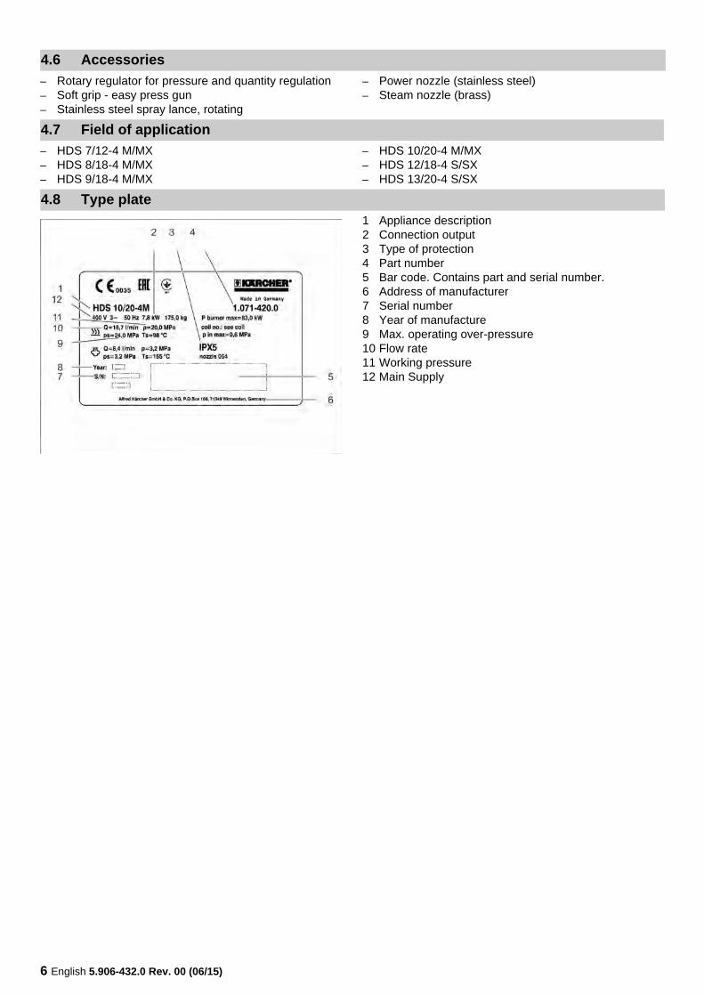
1 Appliance description2 Connection output3 Type of protection4 Part number5 Bar code. Contains part and serial number.6 Address of manufacturer7 Serial number8 Year of manufacture9 Max. operating over-pressure10 Flow rate11 Working pressure12 Main Supply
4.6 Accessories
4.7 Field of application
4.8 Type plate
English 5.906-432.0 Rev. 00 (06/15) 7
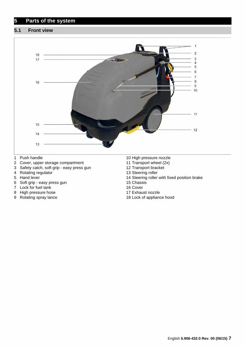
1 Push handle2 Cover, upper storage compartment3 Safety catch, soft grip - easy press gun4 Rotating regulator5 Hand lever6 Soft grip - easy press gun7 Lock for fuel tank8 High pressure hose9 Rotating spray lance
10 High pressure nozzle11 Transport wheel (2x)12 Transport bracket13 Steering roller14 Steering roller with fixed position brake15 Chassis16 Cover17 Exhaust nozzle18 Lock of appliance hood
5 Parts of the system
5.1 Front view
8 English 5.906-432.0 Rev. 00 (06/15)
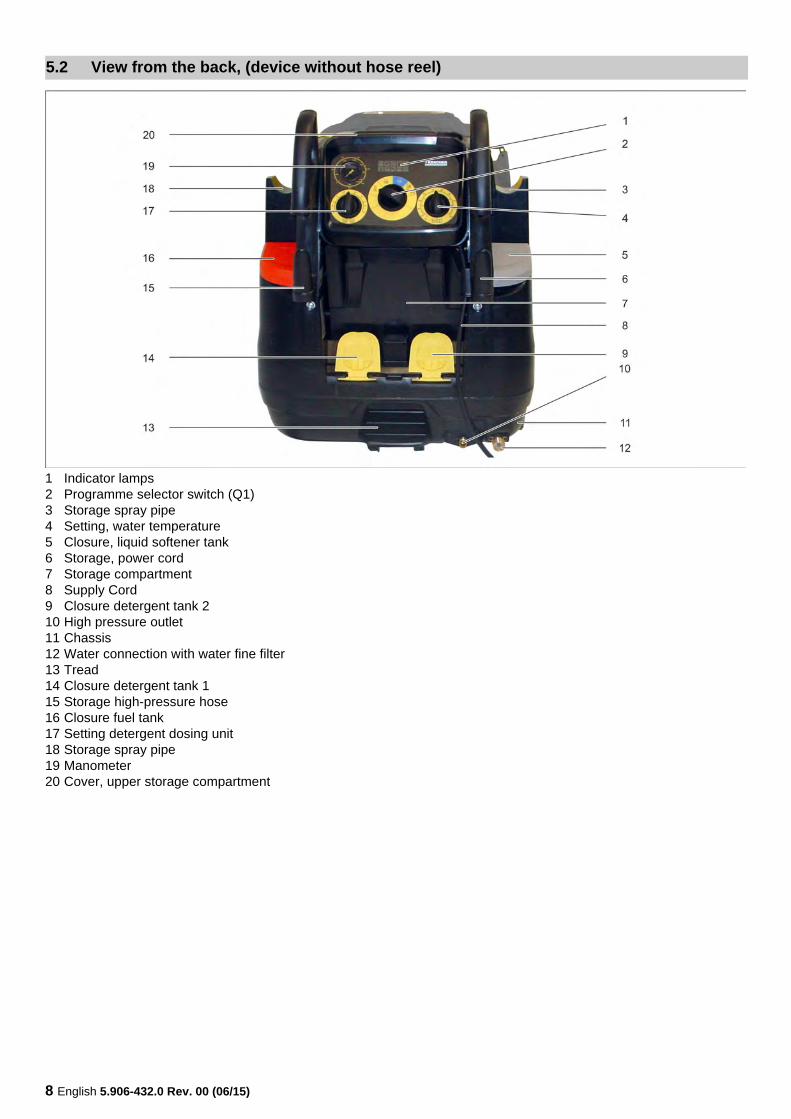
1 Indicator lamps2 Programme selector switch (Q1)3 Storage spray pipe 4 Setting, water temperature5 Closure, liquid softener tank6 Storage, power cord7 Storage compartment8 Supply Cord9 Closure detergent tank 210 High pressure outlet11 Chassis12 Water connection with water fine filter13 Tread14 Closure detergent tank 115 Storage high-pressure hose16 Closure fuel tank17 Setting detergent dosing unit18 Storage spray pipe 19 Manometer20 Cover, upper storage compartment
5.2 View from the back, (device without hose reel)
English 5.906-432.0 Rev. 00 (06/15) 9
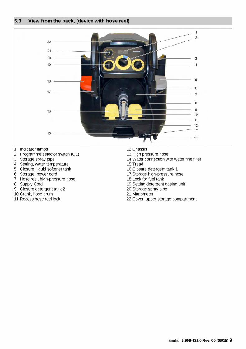
1 Indicator lamps2 Programme selector switch (Q1)3 Storage spray pipe 4 Setting, water temperature5 Closure, liquid softener tank6 Storage, power cord7 Hose reel, high-pressure hose8 Supply Cord9 Closure detergent tank 210 Crank, hose drum11 Recess hose reel lock
12 Chassis13 High pressure hose14 Water connection with water fine filter15 Tread16 Closure detergent tank 117 Storage high-pressure hose18 Lock for fuel tank19 Setting detergent dosing unit20 Storage spray pipe 21 Manometer22 Cover, upper storage compartment
5.3 View from the back, (device with hose reel)
10 English 5.906-432.0 Rev. 00 (06/15)
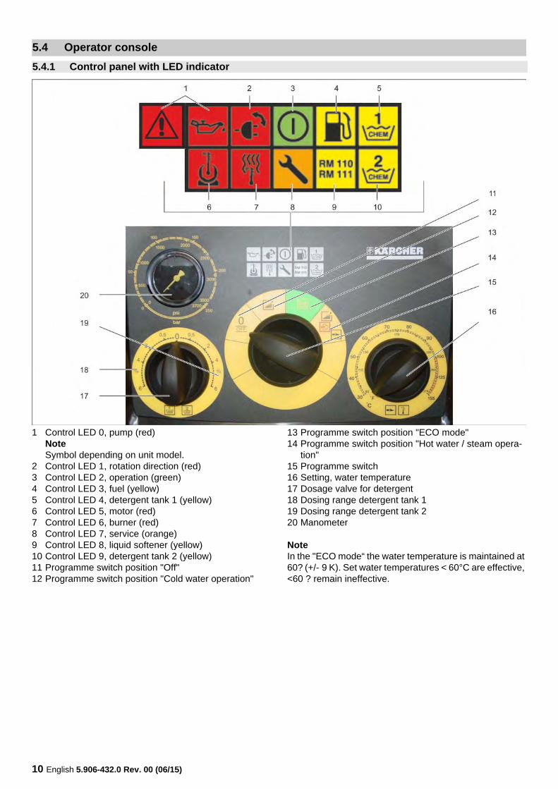
1 Control LED 0, pump (red)NoteSymbol depending on unit model.
2 Control LED 1, rotation direction (red)3 Control LED 2, operation (green)4 Control LED 3, fuel (yellow)5 Control LED 4, detergent tank 1 (yellow)6 Control LED 5, motor (red)7 Control LED 6, burner (red)8 Control LED 7, service (orange)9 Control LED 8, liquid softener (yellow)10 Control LED 9, detergent tank 2 (yellow)11 Programme switch position "Off"12 Programme switch position "Cold water operation"
13 Programme switch position "ECO mode"14 Programme switch position "Hot water / steam opera-
tion"15 Programme switch16 Setting, water temperature17 Dosage valve for detergent18 Dosing range detergent tank 119 Dosing range detergent tank 220 Manometer
NoteIn the "ECO mode“ the water temperature is maintained at 60? (+/- 9 K). Set water temperatures < 60°C are effective, <60 ? remain ineffective.
5.4 Operator console
5.4.1 Control panel with LED indicator
English 5.906-432.0 Rev. 00 (06/15) 11
LED no. Symbol Activity Meaning / measure
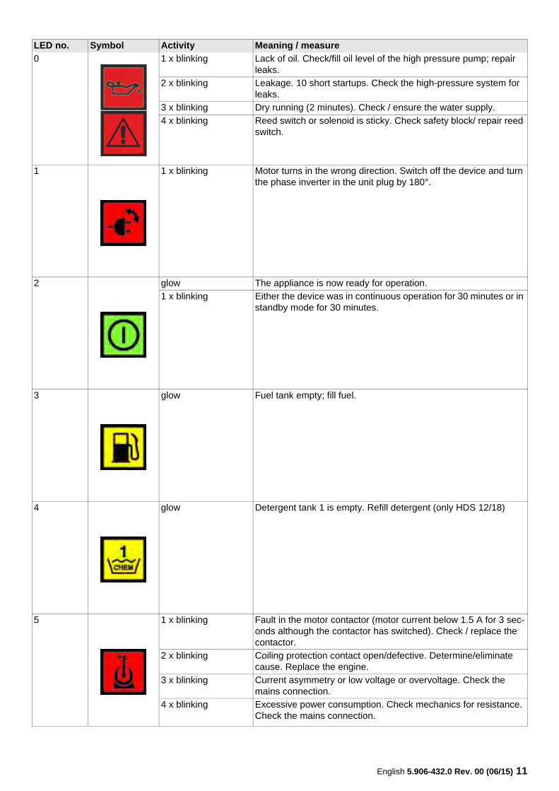
0 1 x blinking Lack of oil. Check/fill oil level of the high pressure pump; repair leaks.
2 x blinking Leakage. 10 short startups. Check the high-pressure system for leaks.
3 x blinking Dry running (2 minutes). Check / ensure the water supply.
4 x blinking Reed switch or solenoid is sticky. Check safety block/ repair reed switch.
1 1 x blinking Motor turns in the wrong direction. Switch off the device and turn the phase inverter in the unit plug by 180°.
2 glow The appliance is now ready for operation.
1 x blinking Either the device was in continuous operation for 30 minutes or in standby mode for 30 minutes.
3 glow Fuel tank empty; fill fuel.
4 glow Detergent tank 1 is empty. Refill detergent (only HDS 12/18)
5 1 x blinking Fault in the motor contactor (motor current below 1.5 A for 3 sec-onds although the contactor has switched). Check / replace the contactor.
2 x blinking Coiling protection contact open/defective. Determine/eliminate cause. Replace the engine.
3 x blinking Current asymmetry or low voltage or overvoltage. Check the mains connection.
4 x blinking Excessive power consumption. Check mechanics for resistance. Check the mains connection.
12 English 5.906-432.0 Rev. 00 (06/15)
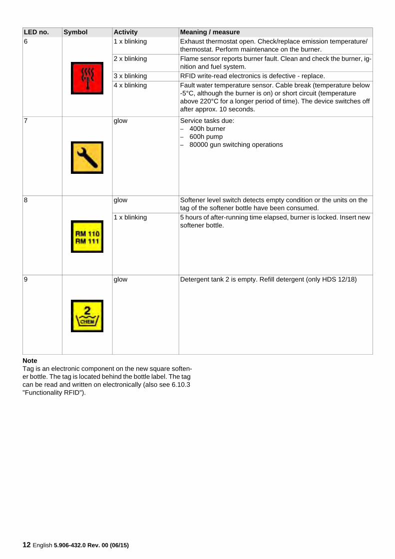
NoteTag is an electronic component on the new square soften-er bottle. The tag is located behind the bottle label. The tag can be read and written on electronically (also see 6.10.3 "Functionality RFID").
6 1 x blinking Exhaust thermostat open. Check/replace emission temperature/thermostat. Perform maintenance on the burner.
2 x blinking Flame sensor reports burner fault. Clean and check the burner, ig-nition and fuel system.
3 x blinking RFID write-read electronics is defective - replace.
4 x blinking Fault water temperature sensor. Cable break (temperature below -5°C, although the burner is on) or short circuit (temperature above 220°C for a longer period of time). The device switches off after approx. 10 seconds.
7 glow Service tasks due:– 400h burner– 600h pump– 80000 gun switching operations
8 glow Softener level switch detects empty condition or the units on the tag of the softener bottle have been consumed.
1 x blinking 5 hours of after-running time elapsed, burner is locked. Insert new softener bottle.
9 glow Detergent tank 2 is empty. Refill detergent (only HDS 12/18)
LED no. Symbol Activity Meaning / measure
English 5.906-432.0 Rev. 00 (06/15) 13
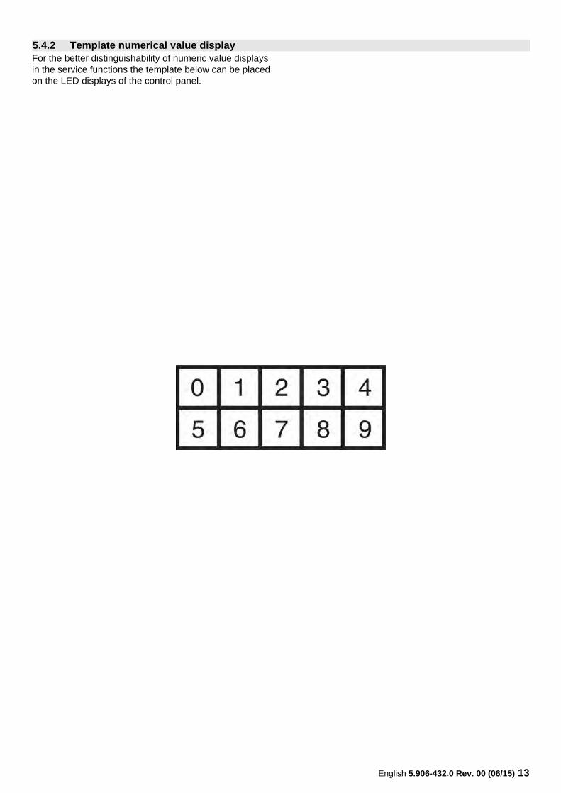
For the better distinguishability of numeric value displays in the service functions the template below can be placed on the LED displays of the control panel.
5.4.2 Template numerical value display

14 English 5.906-432.0 Rev. 00 (06/15)
English 5.906-432.0 Rev. 00 (06/15) 15
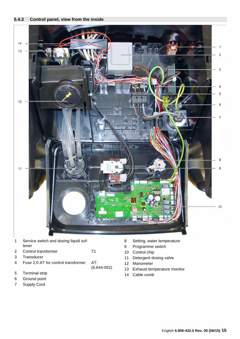
5.4.3 Control panel, view from the inside
1 Service switch and dosing liquid sof-tener
2 Control transformer T1
3 Transducer
4 Fuse 2.0 AT for control transformer AT:(6.644-052)
5 Terminal strip
6 Ground point
7 Supply Cord
8 Setting, water temperature
9 Programme switch
10 Control chip
11 Detergent dosing valve
12 Manometer
13 Exhaust temperature monitor
14 Cable comb
16 English 5.906-432.0 Rev. 00 (06/15)
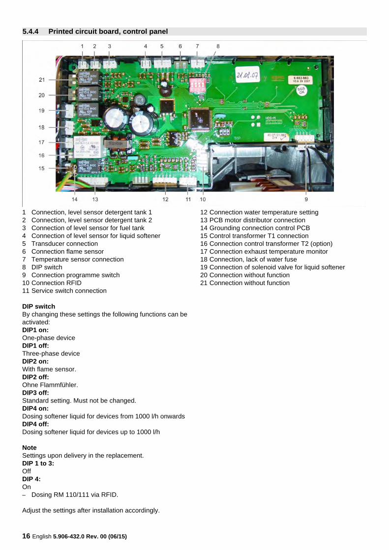
1 Connection, level sensor detergent tank 12 Connection, level sensor detergent tank 23 Connection of level sensor for fuel tank4 Connection of level sensor for liquid softener5 Transducer connection6 Connection flame sensor7 Temperature sensor connection8 DIP switch9 Connection programme switch10 Connection RFID11 Service switch connection
12 Connection water temperature setting13 PCB motor distributor connection14 Grounding connection control PCB15 Control transformer T1 connection16 Connection control transformer T2 (option)17 Connection exhaust temperature monitor18 Connection, lack of water fuse19 Connection of solenoid valve for liquid softener20 Connection without function21 Connection without function
DIP switchBy changing these settings the following functions can be activated:DIP1 on:One-phase deviceDIP1 off:Three-phase deviceDIP2 on:With flame sensor.DIP2 off:Ohne Flammfühler.DIP3 off:Standard setting. Must not be changed.DIP4 on:Dosing softener liquid for devices from 1000 l/h onwardsDIP4 off:Dosing softener liquid for devices up to 1000 l/h
NoteSettings upon delivery in the replacement.DIP 1 to 3:OffDIP 4:On– Dosing RM 110/111 via RFID.
Adjust the settings after installation accordingly.
5.4.4 Printed circuit board, control panel
English 5.906-432.0 Rev. 00 (06/15) 17
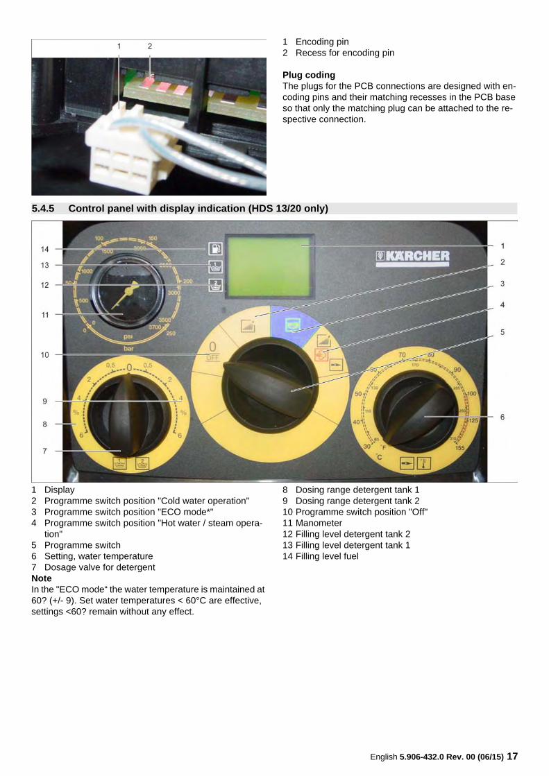
1 Encoding pin2 Recess for encoding pin
Plug codingThe plugs for the PCB connections are designed with en-coding pins and their matching recesses in the PCB base so that only the matching plug can be attached to the re-spective connection.
1 Display2 Programme switch position "Cold water operation"3 Programme switch position "ECO mode*"4 Programme switch position "Hot water / steam opera-
tion"5 Programme switch6 Setting, water temperature7 Dosage valve for detergent
8 Dosing range detergent tank 19 Dosing range detergent tank 210 Programme switch position "Off"11 Manometer12 Filling level detergent tank 213 Filling level detergent tank 114 Filling level fuel
NoteIn the "ECO mode“ the water temperature is maintained at 60? (+/- 9). Set water temperatures < 60°C are effective, settings <60? remain without any effect.
5.4.5 Control panel with display indication (HDS 13/20 only)
18 English 5.906-432.0 Rev. 00 (06/15)
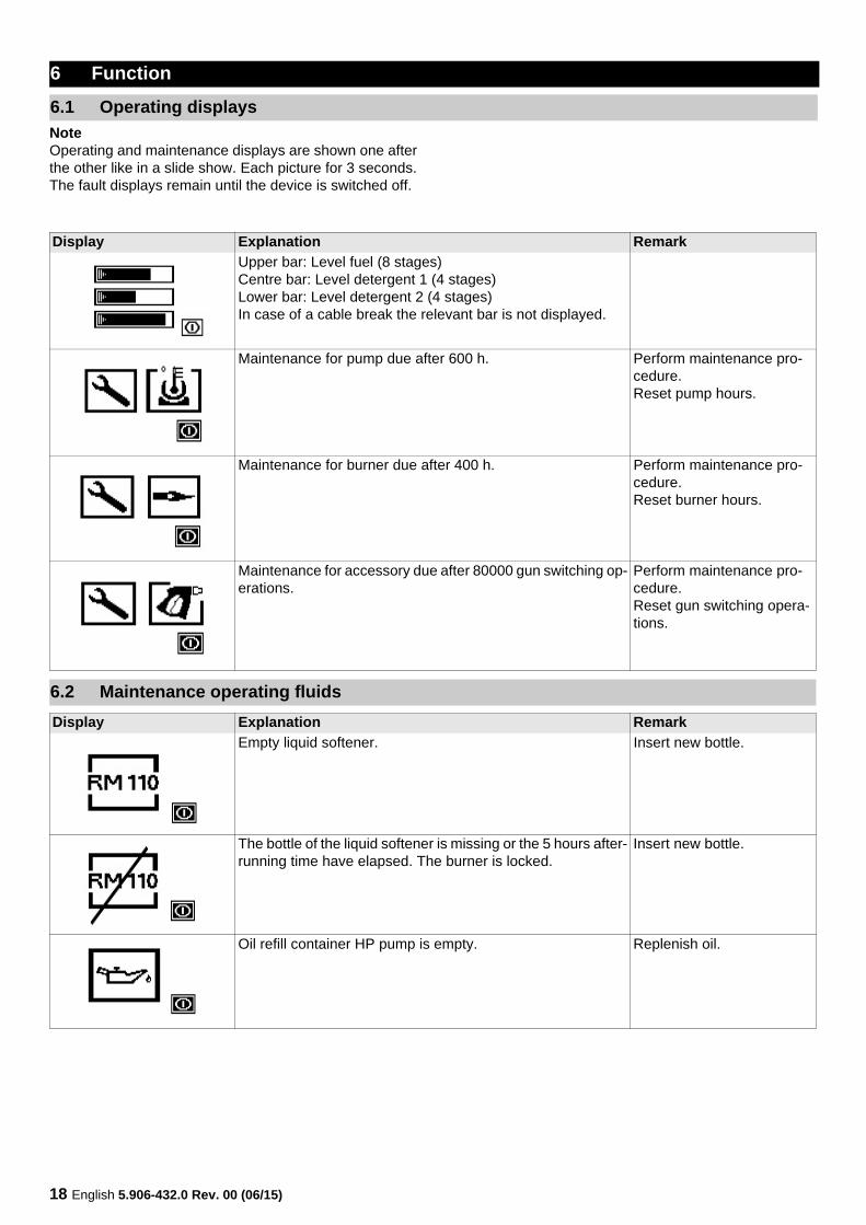
NoteOperating and maintenance displays are shown one after the other like in a slide show. Each picture for 3 seconds.The fault displays remain until the device is switched off.
6 Function
6.1 Operating displays
Display Explanation Remark
Upper bar: Level fuel (8 stages)Centre bar: Level detergent 1 (4 stages)Lower bar: Level detergent 2 (4 stages)In case of a cable break the relevant bar is not displayed.
Maintenance for pump due after 600 h. Perform maintenance pro-cedure.Reset pump hours.
Maintenance for burner due after 400 h. Perform maintenance pro-cedure.Reset burner hours.
Maintenance for accessory due after 80000 gun switching op-erations.
Perform maintenance pro-cedure.Reset gun switching opera-tions.
6.2 Maintenance operating fluids
Display Explanation Remark
Empty liquid softener. Insert new bottle.
The bottle of the liquid softener is missing or the 5 hours after-running time have elapsed. The burner is locked.
Insert new bottle.
Oil refill container HP pump is empty. Replenish oil.
English 5.906-432.0 Rev. 00 (06/15) 19
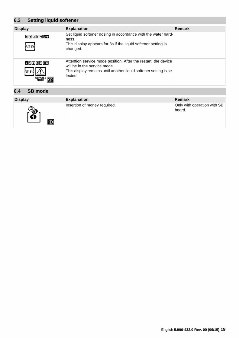
6.3 Setting liquid softener
Display Explanation Remark
Set liquid softener dosing in accordance with the water hard-ness.This display appears for 3s if the liquid softener setting is changed.
Attention service mode position. After the restart, the device will be in the service mode.This display remains until another liquid softener setting is se-lected.
6.4 SB mode
Display Explanation Remark
Insertion of money required. Only with operation with SB board.
20 English 5.906-432.0 Rev. 00 (06/15)
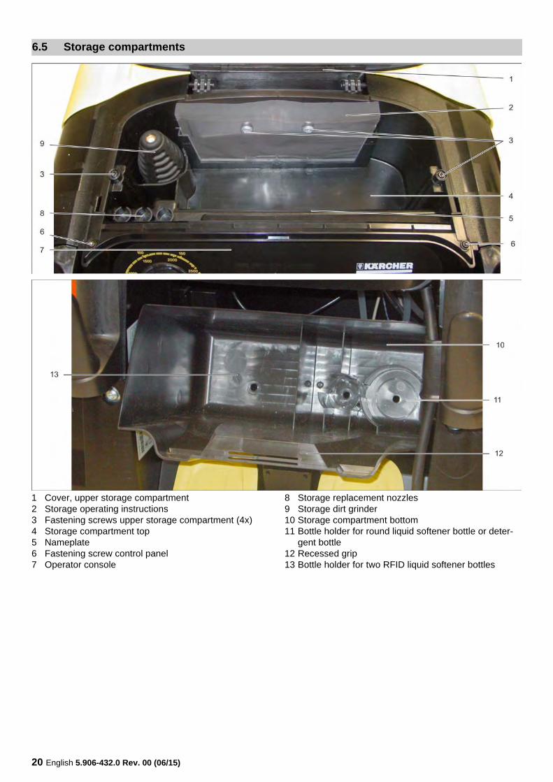
1 Cover, upper storage compartment2 Storage operating instructions3 Fastening screws upper storage compartment (4x)4 Storage compartment top5 Nameplate6 Fastening screw control panel7 Operator console
8 Storage replacement nozzles9 Storage dirt grinder10 Storage compartment bottom11 Bottle holder for round liquid softener bottle or deter-
gent bottle12 Recessed grip13 Bottle holder for two RFID liquid softener bottles
6.5 Storage compartments
English 5.906-432.0 Rev. 00 (06/15) 21
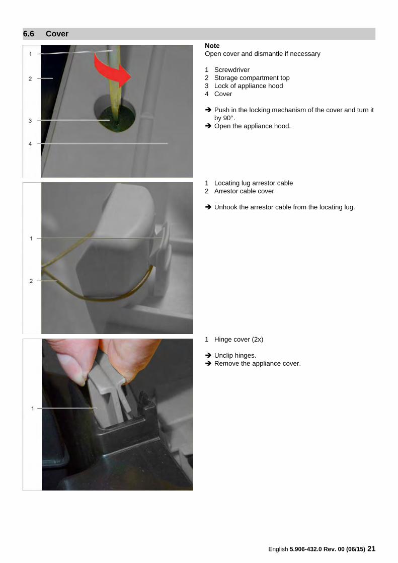
NoteOpen cover and dismantle if necessary
1 Screwdriver2 Storage compartment top3 Lock of appliance hood4 Cover
Push in the locking mechanism of the cover and turn it by 90°.
Open the appliance hood.
1 Locating lug arrestor cable2 Arrestor cable cover
Unhook the arrestor cable from the locating lug.
1 Hinge cover (2x)
Unclip hinges. Remove the appliance cover.
6.6 Cover
22 English 5.906-432.0 Rev. 00 (06/15)
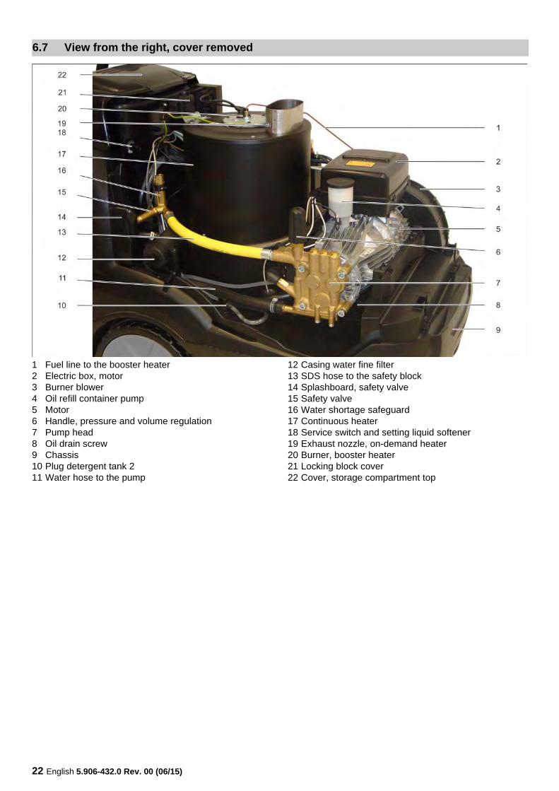
1 Fuel line to the booster heater2 Electric box, motor3 Burner blower4 Oil refill container pump5 Motor6 Handle, pressure and volume regulation7 Pump head8 Oil drain screw9 Chassis10 Plug detergent tank 211 Water hose to the pump
12 Casing water fine filter13 SDS hose to the safety block14 Splashboard, safety valve15 Safety valve16 Water shortage safeguard17 Continuous heater18 Service switch and setting liquid softener19 Exhaust nozzle, on-demand heater20 Burner, booster heater21 Locking block cover22 Cover, storage compartment top
6.7 View from the right, cover removed
English 5.906-432.0 Rev. 00 (06/15) 23
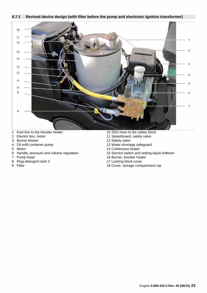
1 Fuel line to the booster heater2 Electric box, motor3 Burner blower4 Oil refill container pump5 Motor6 Handle, pressure and volume regulation7 Pump head8 Plug detergent tank 29 Filter
10 SDS hose to the safety block11 Splashboard, safety valve12 Safety valve13 Water shortage safeguard14 Continuous heater15 Service switch and setting liquid softener16 Burner, booster heater17 Locking block cover18 Cover, storage compartment top
6.7.1 Revised device design (with filter before the pump and electronic ignition transformer)
24 English 5.906-432.0 Rev. 00 (06/15)
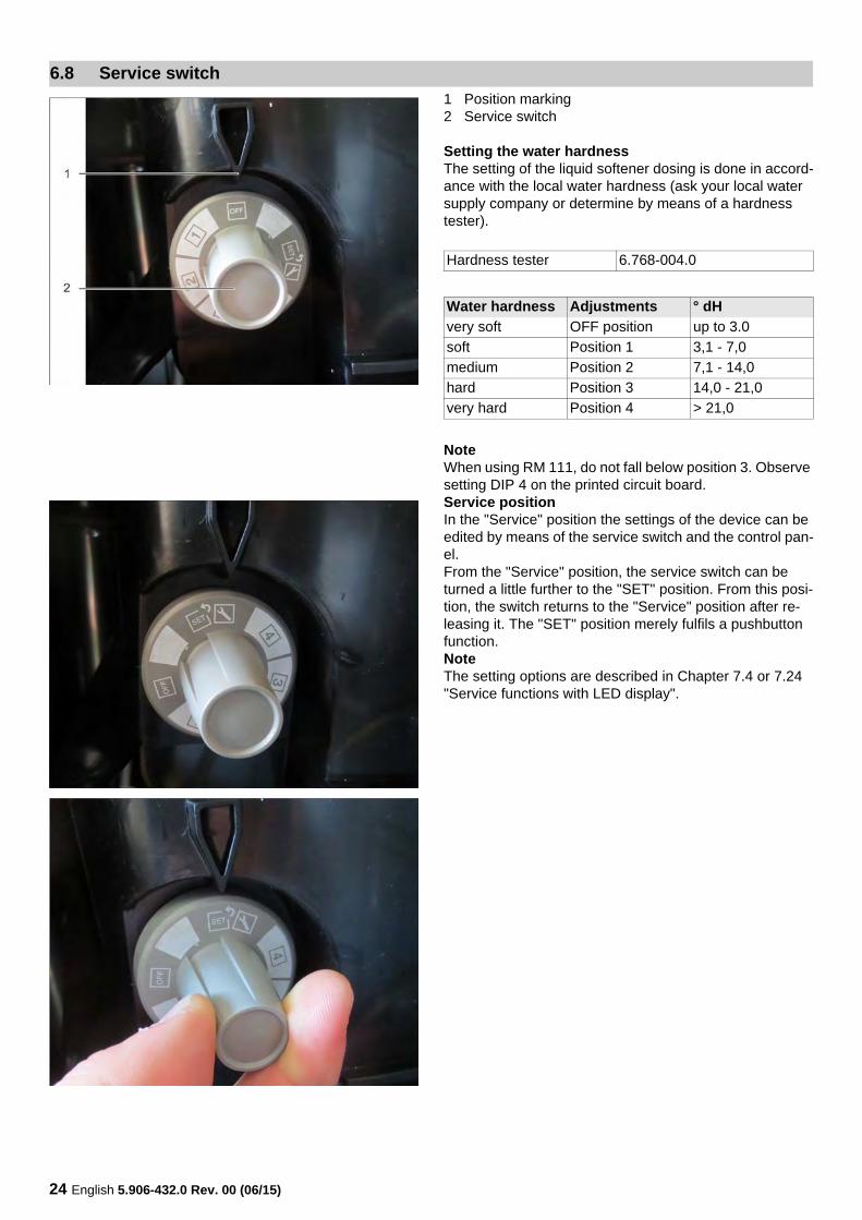
1 Position marking2 Service switch
Setting the water hardnessThe setting of the liquid softener dosing is done in accord-ance with the local water hardness (ask your local water supply company or determine by means of a hardness tester).
NoteWhen using RM 111, do not fall below position 3. Observe setting DIP 4 on the printed circuit board.Service positionIn the "Service" position the settings of the device can be edited by means of the service switch and the control pan-el.From the "Service" position, the service switch can be turned a little further to the "SET" position. From this posi-tion, the switch returns to the "Service" position after re-leasing it. The "SET" position merely fulfils a pushbutton function.NoteThe setting options are described in Chapter 7.4 or 7.24 "Service functions with LED display".
6.8 Service switch
Hardness tester 6.768-004.0
Water hardness Adjustments ° dH
very soft OFF position up to 3.0
soft Position 1 3,1 - 7,0
medium Position 2 7,1 - 14,0
hard Position 3 14,0 - 21,0
very hard Position 4 > 21,0
English 5.906-432.0 Rev. 00 (06/15) 25
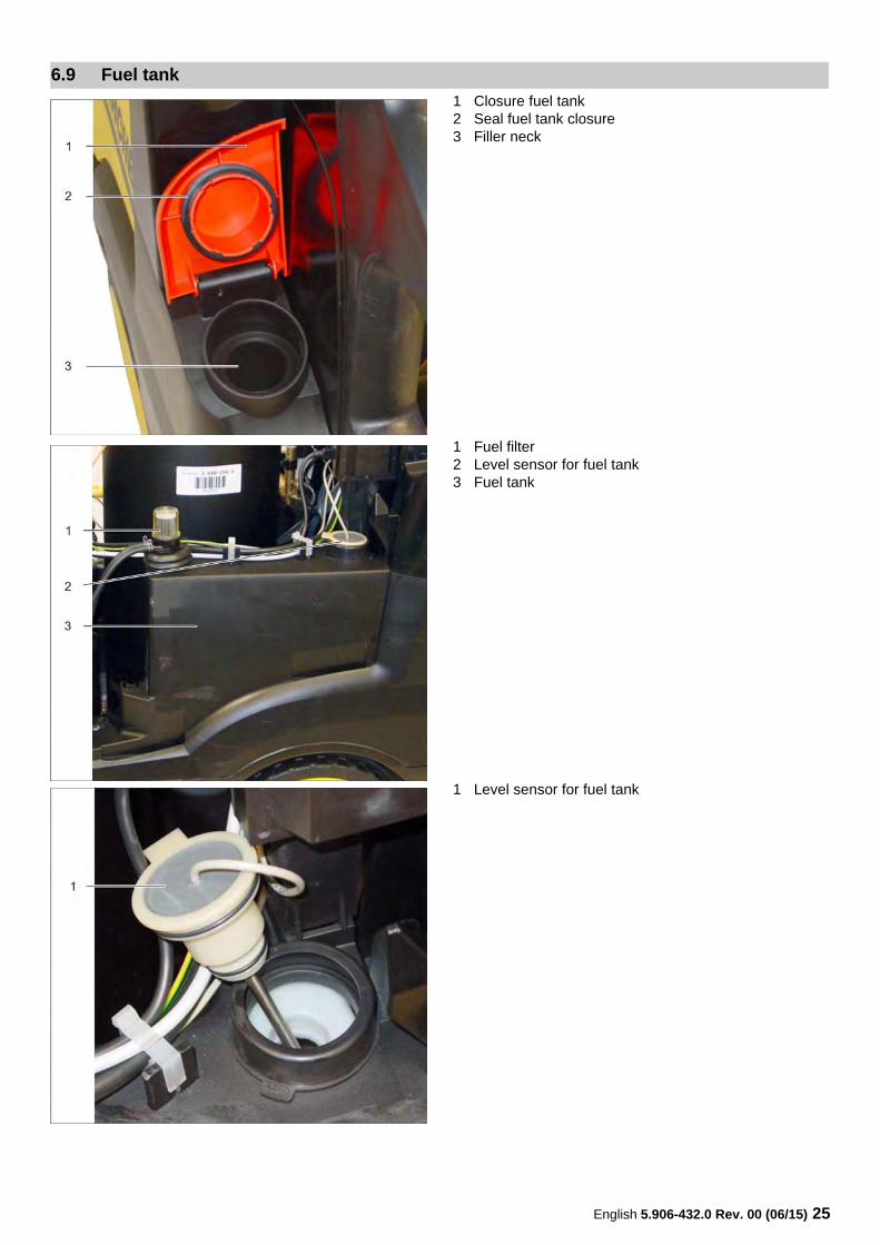
1 Closure fuel tank2 Seal fuel tank closure3 Filler neck
1 Fuel filter2 Level sensor for fuel tank3 Fuel tank
1 Level sensor for fuel tank
6.9 Fuel tank
26 English 5.906-432.0 Rev. 00 (06/15)
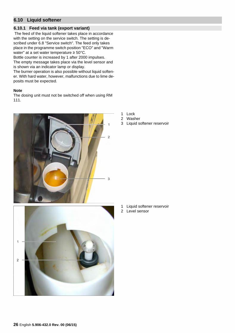
The feed of the liquid softener takes place in accordance with the setting on the service switch. The setting is de-scribed under 6.8 "Service switch". The feed only takes place in the programme switch position "ECO" and "Warm water" at a set water temperature ≥ 50°C.Bottle counter is increased by 1 after 2000 impulses.The empty message takes place via the level sensor and is shown via an indicator lamp or display.The burner operation is also possible without liquid soften-er. With hard water, however, malfunctions due to lime de-posits must be expected.
NoteThe dosing unit must not be switched off when using RM 111.
1 Lock2 Washer3 Liquid softener reservoir
1 Liquid softener reservoir2 Level sensor
6.10 Liquid softener
6.10.1 Feed via tank (export variant)
English 5.906-432.0 Rev. 00 (06/15) 27
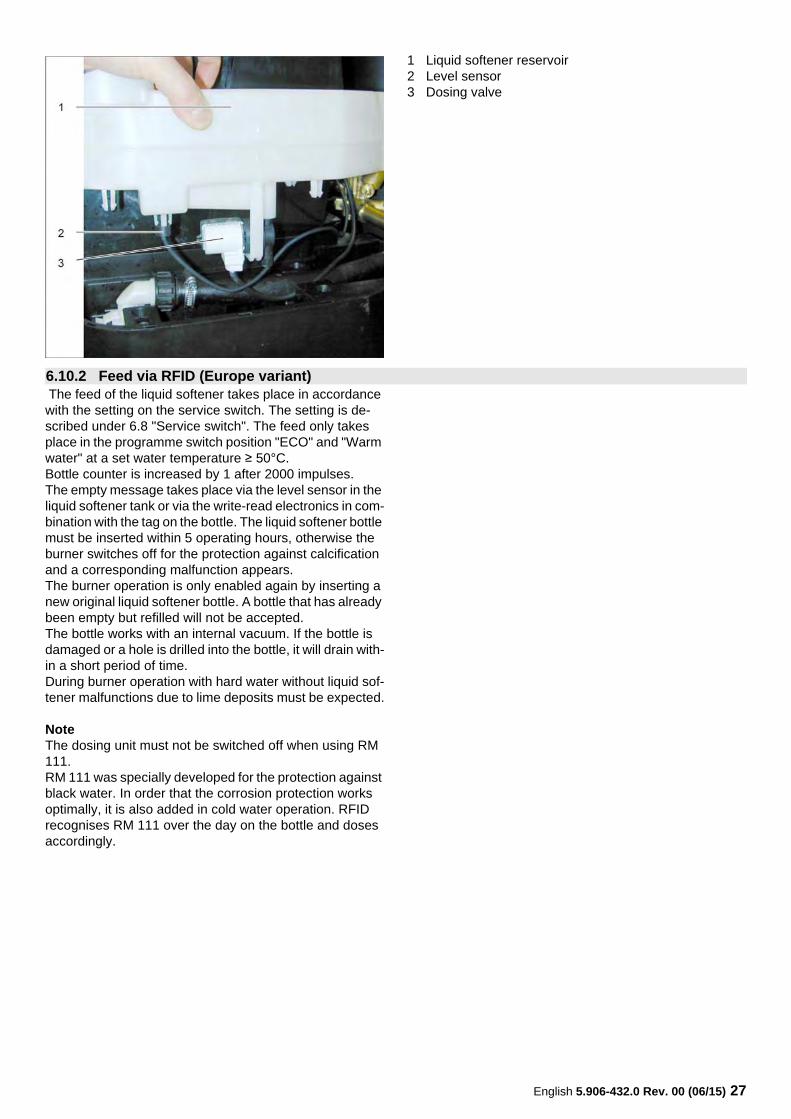
1 Liquid softener reservoir2 Level sensor3 Dosing valve
The feed of the liquid softener takes place in accordance with the setting on the service switch. The setting is de-scribed under 6.8 "Service switch". The feed only takes place in the programme switch position "ECO" and "Warm water" at a set water temperature ≥ 50°C.Bottle counter is increased by 1 after 2000 impulses.The empty message takes place via the level sensor in the liquid softener tank or via the write-read electronics in com-bination with the tag on the bottle. The liquid softener bottle must be inserted within 5 operating hours, otherwise the burner switches off for the protection against calcification and a corresponding malfunction appears.The burner operation is only enabled again by inserting a new original liquid softener bottle. A bottle that has already been empty but refilled will not be accepted.The bottle works with an internal vacuum. If the bottle is damaged or a hole is drilled into the bottle, it will drain with-in a short period of time.During burner operation with hard water without liquid sof-tener malfunctions due to lime deposits must be expected.
NoteThe dosing unit must not be switched off when using RM 111.RM 111 was specially developed for the protection against black water. In order that the corrosion protection works optimally, it is also added in cold water operation. RFID recognises RM 111 over the day on the bottle and doses accordingly.
6.10.2 Feed via RFID (Europe variant)

28 English 5.906-432.0 Rev. 00 (06/15)
1 Liquid softener bottle2 Screws3 RFID - attachment
1 RFID - attachment2 Bottle opener - insertion
1 Liquid softener bottle2 Sealing
NoteThe sealing is pierced upon inserting the bottle.
English 5.906-432.0 Rev. 00 (06/15) 29
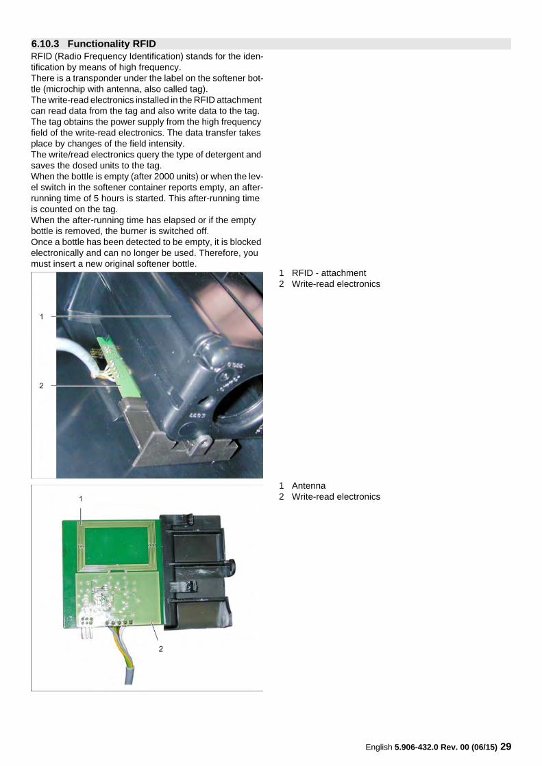
RFID (Radio Frequency Identification) stands for the iden-tification by means of high frequency.There is a transponder under the label on the softener bot-tle (microchip with antenna, also called tag).The write-read electronics installed in the RFID attachment can read data from the tag and also write data to the tag. The tag obtains the power supply from the high frequency field of the write-read electronics. The data transfer takes place by changes of the field intensity.The write/read electronics query the type of detergent and saves the dosed units to the tag.When the bottle is empty (after 2000 units) or when the lev-el switch in the softener container reports empty, an after-running time of 5 hours is started. This after-running time is counted on the tag.When the after-running time has elapsed or if the empty bottle is removed, the burner is switched off.Once a bottle has been detected to be empty, it is blocked electronically and can no longer be used. Therefore, you must insert a new original softener bottle.
1 RFID - attachment2 Write-read electronics
1 Antenna2 Write-read electronics
6.10.3 Functionality RFID
30 English 5.906-432.0 Rev. 00 (06/15)
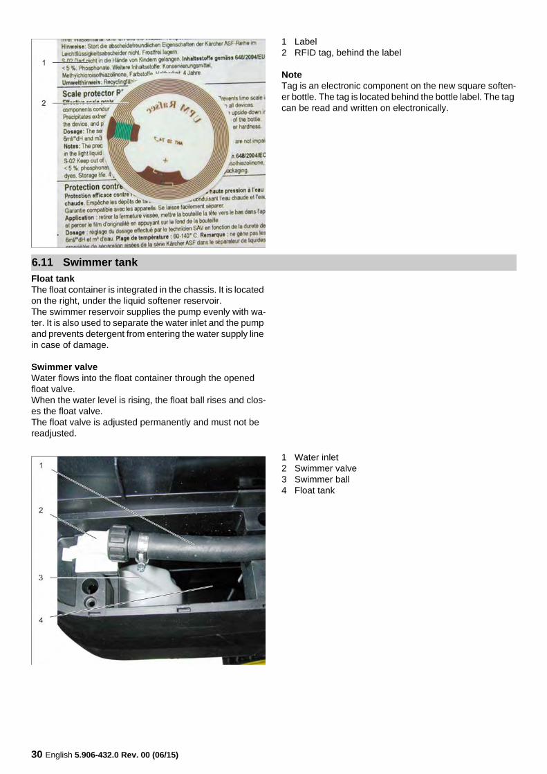
1 Label2 RFID tag, behind the label
NoteTag is an electronic component on the new square soften-er bottle. The tag is located behind the bottle label. The tag can be read and written on electronically.
Float tankThe float container is integrated in the chassis. It is located on the right, under the liquid softener reservoir.The swimmer reservoir supplies the pump evenly with wa-ter. It is also used to separate the water inlet and the pump and prevents detergent from entering the water supply line in case of damage.
Swimmer valveWater flows into the float container through the opened float valve.When the water level is rising, the float ball rises and clos-es the float valve.The float valve is adjusted permanently and must not be readjusted.
1 Water inlet2 Swimmer valve3 Swimmer ball4 Float tank
6.11 Swimmer tank
English 5.906-432.0 Rev. 00 (06/15) 31
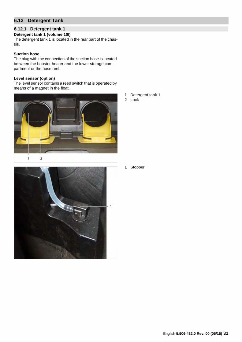
Detergent tank 1 (volume 10l)The detergent tank 1 is located in the rear part of the chas-sis.
Suction hoseThe plug with the connection of the suction hose is located between the booster heater and the lower storage com-partment or the hose reel.
Level sensor (option)The level sensor contains a reed switch that is operated by means of a magnet in the float.
1 Detergent tank 12 Lock
1 Stopper
6.12 Detergent Tank
6.12.1 Detergent tank 1
32 English 5.906-432.0 Rev. 00 (06/15)
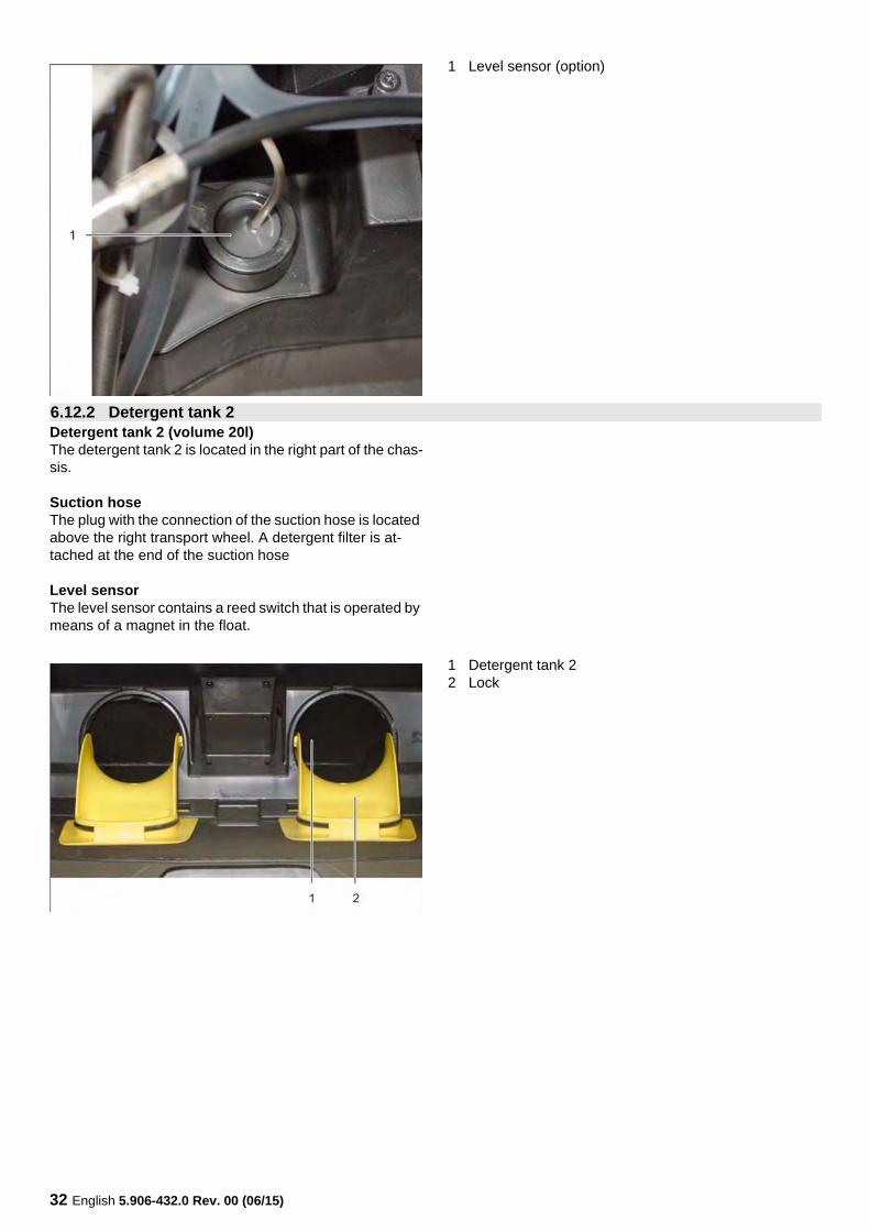
1 Level sensor (option)
Detergent tank 2 (volume 20l)The detergent tank 2 is located in the right part of the chas-sis.
Suction hoseThe plug with the connection of the suction hose is located above the right transport wheel. A detergent filter is at-tached at the end of the suction hose
Level sensorThe level sensor contains a reed switch that is operated by means of a magnet in the float.
1 Detergent tank 22 Lock
6.12.2 Detergent tank 2
English 5.906-432.0 Rev. 00 (06/15) 33
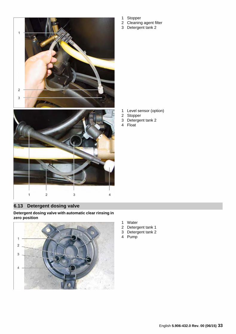
1 Stopper2 Cleaning agent filter3 Detergent tank 2
1 Level sensor (option)2 Stopper3 Detergent tank 24 Float
Detergent dosing valve with automatic clear rinsing in zero position
1 Water2 Detergent tank 13 Detergent tank 24 Pump
6.13 Detergent dosing valve
34 English 5.906-432.0 Rev. 00 (06/15)
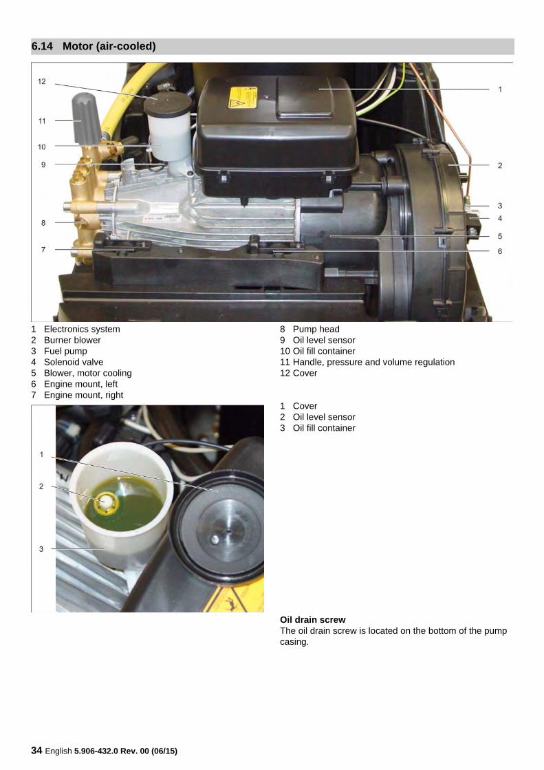
1 Electronics system2 Burner blower3 Fuel pump4 Solenoid valve5 Blower, motor cooling6 Engine mount, left7 Engine mount, right
8 Pump head9 Oil level sensor10 Oil fill container11 Handle, pressure and volume regulation12 Cover
1 Cover2 Oil level sensor3 Oil fill container
Oil drain screwThe oil drain screw is located on the bottom of the pump casing.
6.14 Motor (air-cooled)
English 5.906-432.0 Rev. 00 (06/15) 35
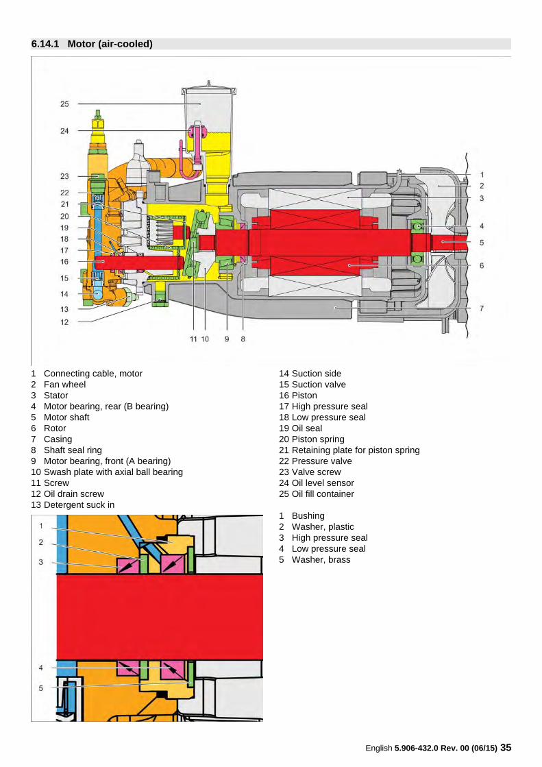
1 Connecting cable, motor2 Fan wheel3 Stator4 Motor bearing, rear (B bearing)5 Motor shaft6 Rotor7 Casing8 Shaft seal ring9 Motor bearing, front (A bearing)10 Swash plate with axial ball bearing11 Screw12 Oil drain screw13 Detergent suck in
14 Suction side15 Suction valve16 Piston17 High pressure seal18 Low pressure seal19 Oil seal20 Piston spring21 Retaining plate for piston spring22 Pressure valve23 Valve screw24 Oil level sensor25 Oil fill container
1 Bushing2 Washer, plastic3 High pressure seal4 Low pressure seal5 Washer, brass
6.14.1 Motor (air-cooled)
36 English 5.906-432.0 Rev. 00 (06/15)
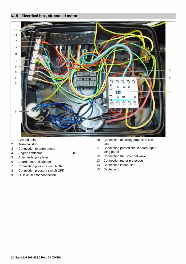
6.15 Electrical box, air-cooled motor
1 Ground point
2 Terminal strip
3 Connection to earth, motor
4 Engine contactor K1
5 Anti-interference filter
6 Board, motor distributor
7 Connection pressure switch ON
8 Connection pressure switch OFF
9 Oil level sensor connection
10 Connection of coiling protection con-tact
11 Connection printed circuit board, oper-ating panel
12 Connection fuel solenoid valve
13 Connection motor protection
14 Connection is not used
15 Cable comb
English 5.906-432.0 Rev. 00 (06/15) 37
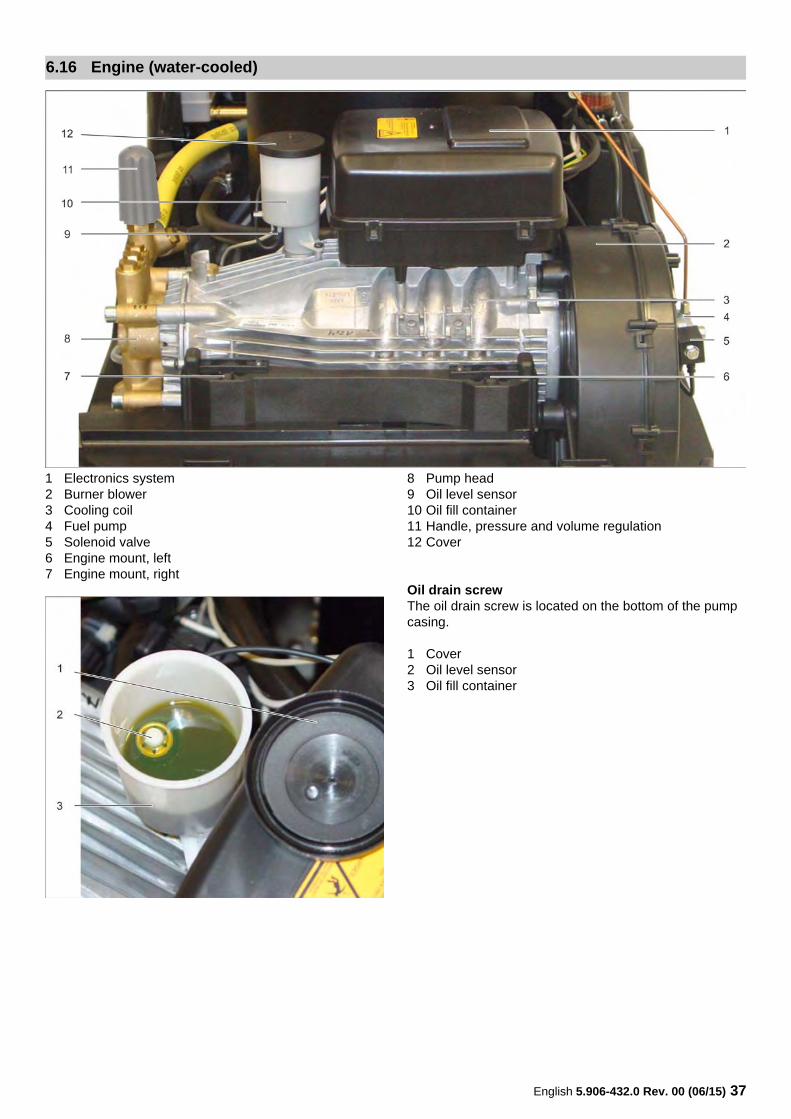
1 Electronics system2 Burner blower3 Cooling coil4 Fuel pump5 Solenoid valve6 Engine mount, left7 Engine mount, right
8 Pump head9 Oil level sensor10 Oil fill container11 Handle, pressure and volume regulation12 Cover
Oil drain screwThe oil drain screw is located on the bottom of the pump casing.
1 Cover2 Oil level sensor3 Oil fill container
6.16 Engine (water-cooled)
38 English 5.906-432.0 Rev. 00 (06/15)
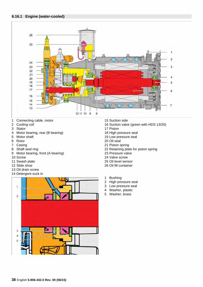
1 Connecting cable, motor2 Cooling coil3 Stator4 Motor bearing, rear (B bearing)5 Motor shaft6 Rotor7 Casing8 Shaft seal ring9 Motor bearing, front (A bearing)10 Screw11 Swash plate12 Slide shoe13 Oil drain screw14 Detergent suck in
15 Suction side16 Suction valve (green with HDS 13/20)17 Piston18 High pressure seal19 Low pressure seal20 Oil seal21 Piston spring22 Retaining plate for piston spring23 Pressure valve24 Valve screw25 Oil level sensor26 Oil fill container
1 Bushing2 High pressure seal3 Low pressure seal4 Washer, plastic5 Washer, brass
6.16.1 Engine (water-cooled)
English 5.906-432.0 Rev. 00 (06/15) 39
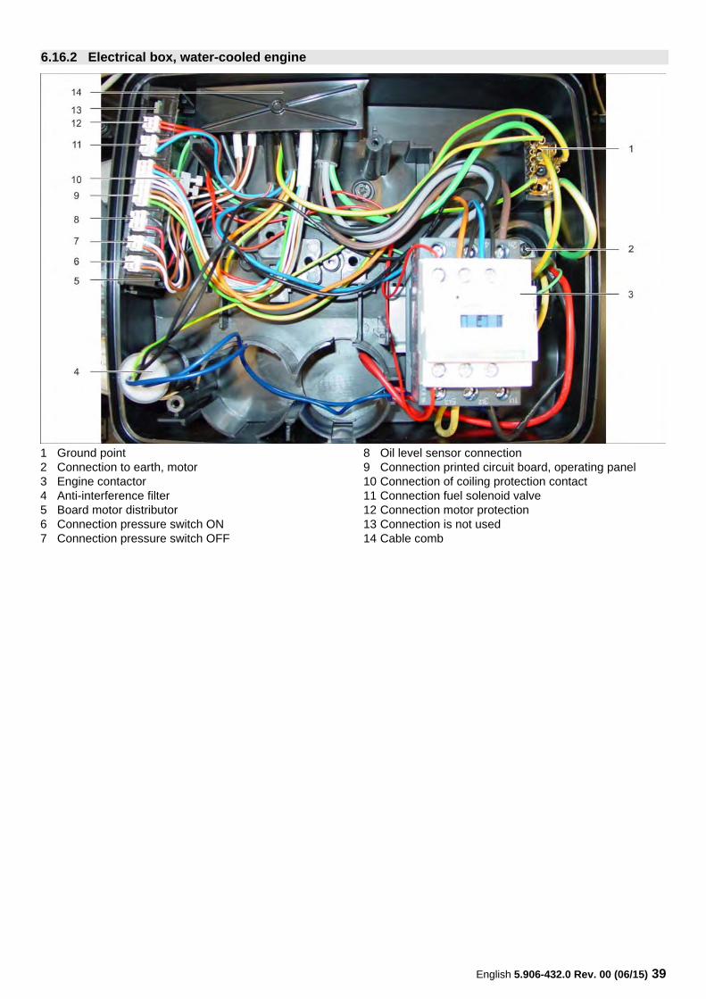
1 Ground point2 Connection to earth, motor3 Engine contactor4 Anti-interference filter5 Board motor distributor6 Connection pressure switch ON7 Connection pressure switch OFF
8 Oil level sensor connection9 Connection printed circuit board, operating panel10 Connection of coiling protection contact11 Connection fuel solenoid valve12 Connection motor protection13 Connection is not used14 Cable comb
6.16.2 Electrical box, water-cooled engine
40 English 5.906-432.0 Rev. 00 (06/15)
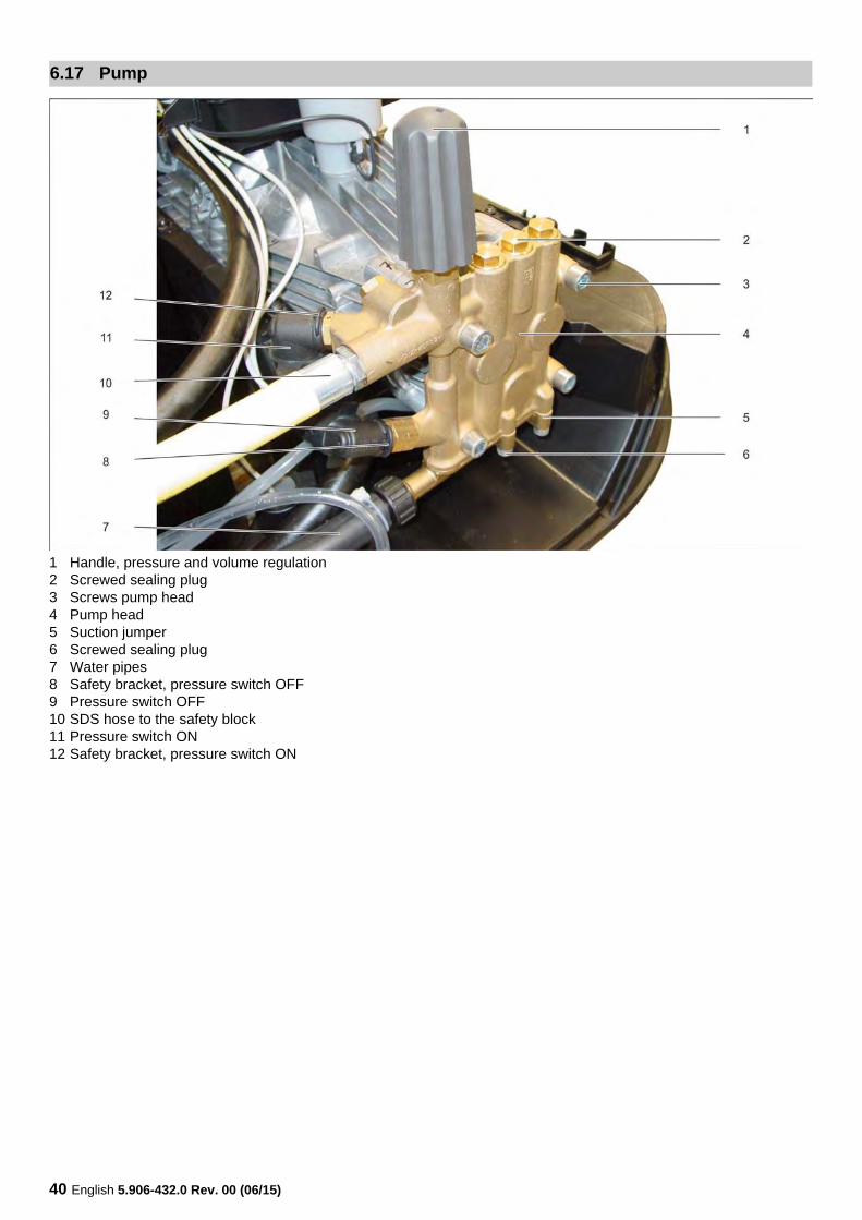
1 Handle, pressure and volume regulation2 Screwed sealing plug3 Screws pump head4 Pump head5 Suction jumper6 Screwed sealing plug7 Water pipes8 Safety bracket, pressure switch OFF9 Pressure switch OFF10 SDS hose to the safety block11 Pressure switch ON12 Safety bracket, pressure switch ON
6.17 Pump
English 5.906-432.0 Rev. 00 (06/15) 41
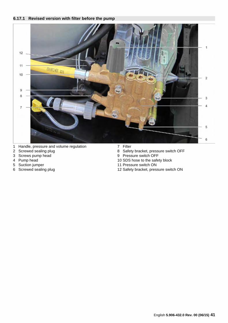
1 Handle, pressure and volume regulation2 Screwed sealing plug3 Screws pump head4 Pump head5 Suction jumper6 Screwed sealing plug
7 Filter8 Safety bracket, pressure switch OFF9 Pressure switch OFF10 SDS hose to the safety block11 Pressure switch ON12 Safety bracket, pressure switch ON
6.17.1 Revised version with filter before the pump
42 English 5.906-432.0 Rev. 00 (06/15)
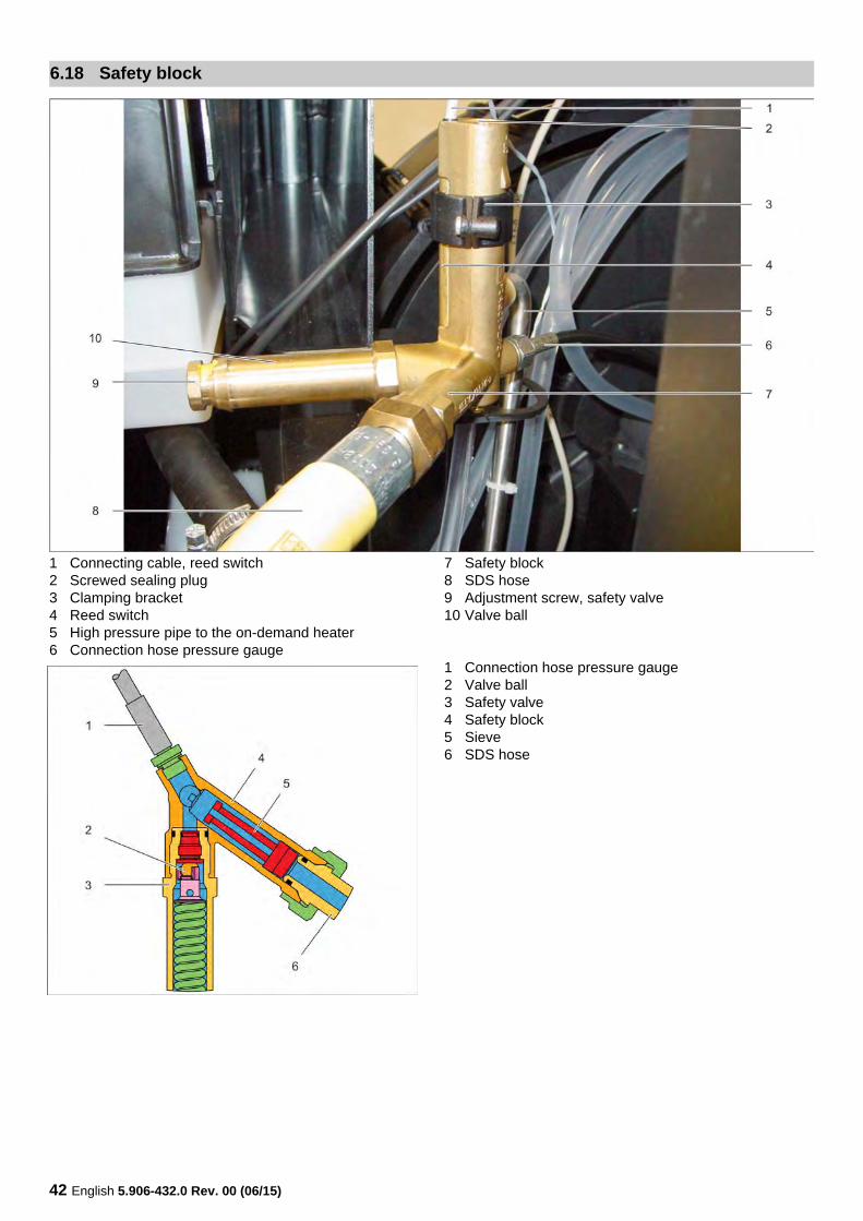
1 Connecting cable, reed switch2 Screwed sealing plug3 Clamping bracket4 Reed switch5 High pressure pipe to the on-demand heater6 Connection hose pressure gauge
7 Safety block8 SDS hose9 Adjustment screw, safety valve10 Valve ball
1 Connection hose pressure gauge2 Valve ball3 Safety valve4 Safety block5 Sieve6 SDS hose
6.18 Safety block
English 5.906-432.0 Rev. 00 (06/15) 43
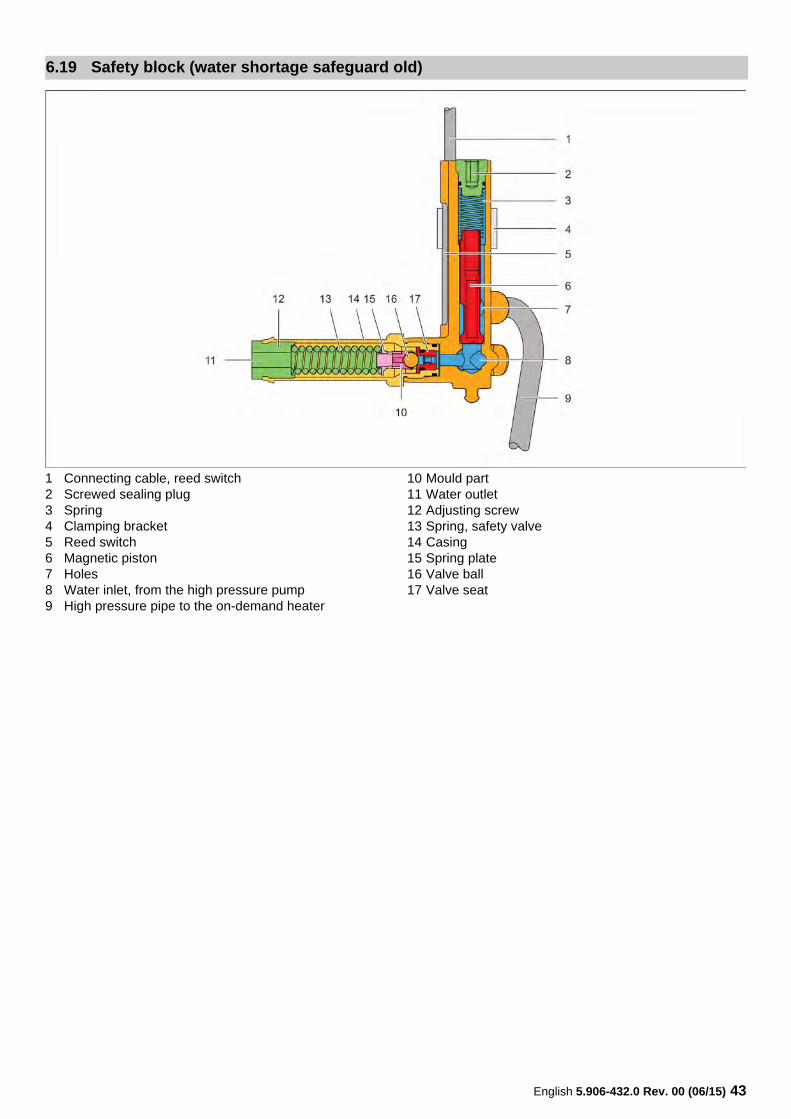
1 Connecting cable, reed switch2 Screwed sealing plug3 Spring4 Clamping bracket5 Reed switch6 Magnetic piston7 Holes8 Water inlet, from the high pressure pump9 High pressure pipe to the on-demand heater
10 Mould part11 Water outlet12 Adjusting screw13 Spring, safety valve14 Casing15 Spring plate16 Valve ball17 Valve seat
6.19 Safety block (water shortage safeguard old)
44 English 5.906-432.0 Rev. 00 (06/15)
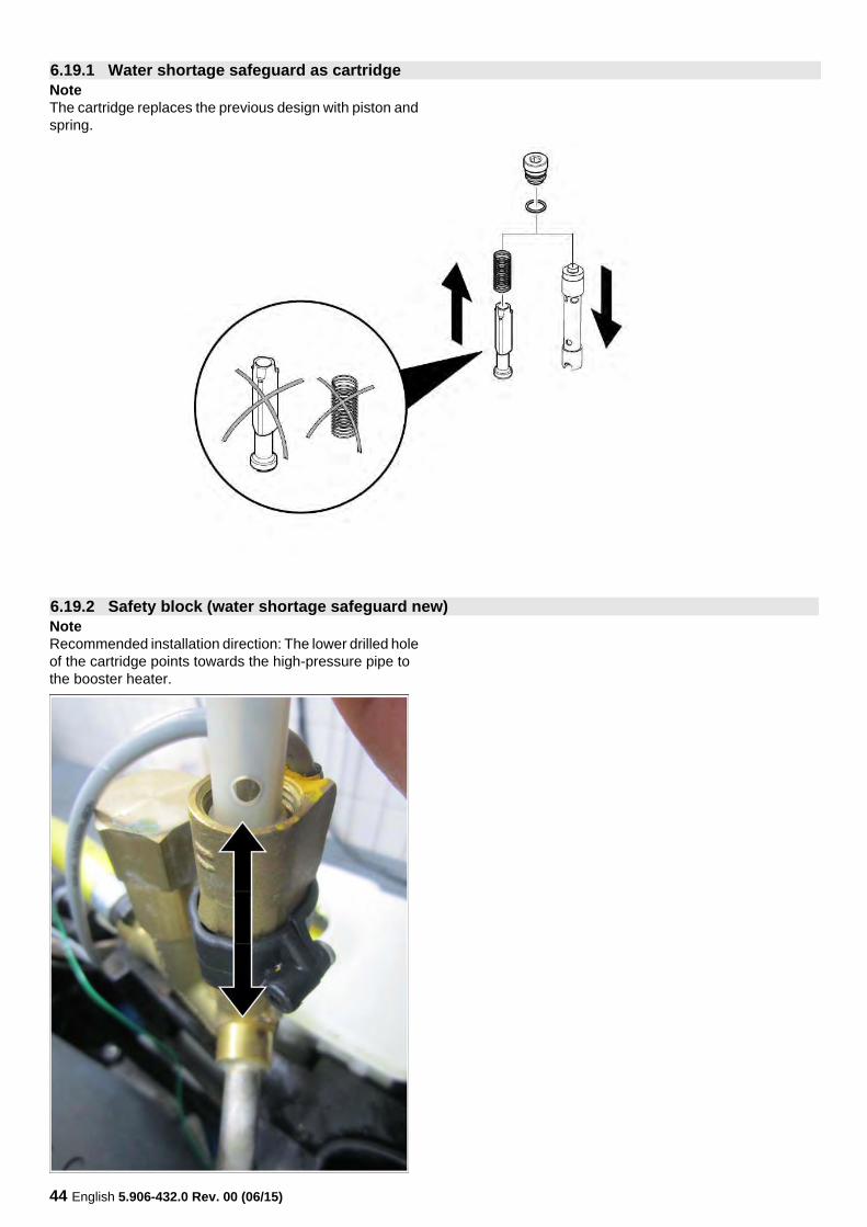
NoteThe cartridge replaces the previous design with piston and spring.
NoteRecommended installation direction: The lower drilled hole of the cartridge points towards the high-pressure pipe to the booster heater.
6.19.1 Water shortage safeguard as cartridge
6.19.2 Safety block (water shortage safeguard new)
English 5.906-432.0 Rev. 00 (06/15) 45
The lack of water fuse prevents the burner from switching on in case of missing or insufficient water volume and thus protects the on-demand heater from overheating.With an opened gun and a sufficient water flow the sole-noid is lifted against the force of gravity in the cartridge.The solenoid piston closes the contact of the reed switch.This opens the fuel solenoid valve and the burner ignites.The sieve in the water supply of the safety block prevents the contamination of the lack of water fuse.The lack of water fuse is a safety component and therefore its locking screw is sealed.The information regarding insufficient water volumes is sent directly to the control PCB.There, this message is evaluated as– lack of water fuse (shut-off of burner, see above) and as– Dry-run protection for the pump (switch-off device).
The lack of water fuse functions immediately.It switches the burner off immediately in case of insufficient water volume and back on after the water level has been replenished.The dry run protection is intitiated when the lack of water fuse signals insufficient water volume for 2 minutes.The appliance shuts off with a fault message and locks up.Only by switching the device off and back on via the main switch, it can be taken into operation again.As the dry-run protection damages the pump in the long run, there must always be a sufficient water supply.
The safety valve guides the entire flow rate of the pump to the float container if the pressure switch or the overflow valve is defective and thus protects the device and acces-sories from inadmissibly high overpressure.If the gun is open, the safety valve is closed and the entire flow volume of the pump is transferred to the gun at oper-ating pressure.If the pressure in the high pressure system rises by ap-prox. 20 bar above the permissible operating pressure, the valve ball is lifted off the valve seat and part of the flow vol-ume flows into the swimmer reservoir. The opening pressure of the safety valve is adjusted with the adjustment screw.Rotation to the right increases the opening pressure, rota-tion to the left decreases the opening pressure.The safety valve is a safety component and therefore its adjustment screw is sealed.
NoteThe safety valve is adjusted via the pressure increase in the system with the burner turned on, so that it limits the pressure increase to the max. permissible value (see Specifciations) with the gun closed.Then seal the settings.
6.19.3 Function water shortage safeguard and dry-run protection
6.19.4 Function of safety valve
46 English 5.906-432.0 Rev. 00 (06/15)
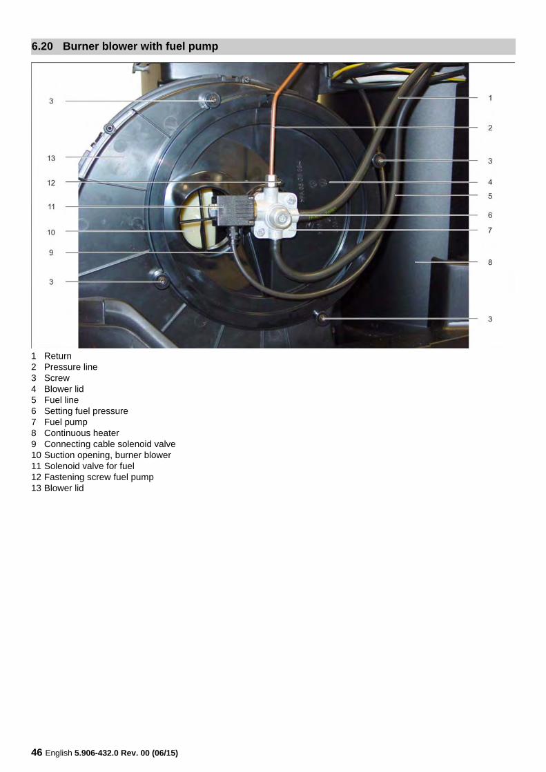
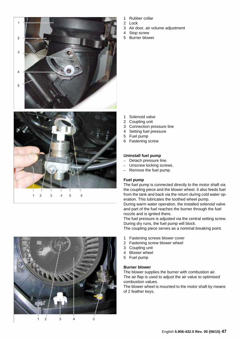
1 Return2 Pressure line3 Screw4 Blower lid5 Fuel line6 Setting fuel pressure7 Fuel pump8 Continuous heater9 Connecting cable solenoid valve10 Suction opening, burner blower11 Solenoid valve for fuel12 Fastening screw fuel pump13 Blower lid
6.20 Burner blower with fuel pump
English 5.906-432.0 Rev. 00 (06/15) 47
1 Rubber collar2 Lock3 Air door, air volume adjustment4 Stop screw5 Burner blower
1 Solenoid valve2 Coupling unit3 Connection pressure line4 Setting fuel pressure5 Fuel pump6 Fastening screw
Uninstall fuel pump– Detach pressure line.– Unscrew locking screws.– Remove the fuel pump.
Fuel pumpThe fuel pump is connected directly to the motor shaft via the coupling piece and the blower wheel. It also feeds fuel from the tank and back via the return during cold water op-eration. This lubricates the toothed wheel pump.During warm water operation, the installed solenoid valve and part of the fuel reaches the burner through the fuel nozzle and is ignited there.The fuel pressure is adjusted via the central setting screw.During dry runs, the fuel pump will block.The coupling piece serves as a nominal breaking point.
1 Fastening screws blower cover2 Fastening screw blower wheel3 Coupling unit4 Blower wheel5 Fuel pump
Burner blowerThe blower supplies the burner with combustion air.The air flap is used to adjust the air value to optimised combustion values.The blower wheel is mounted to the motor shaft by means of 2 feather keys.
48 English 5.906-432.0 Rev. 00 (06/15)
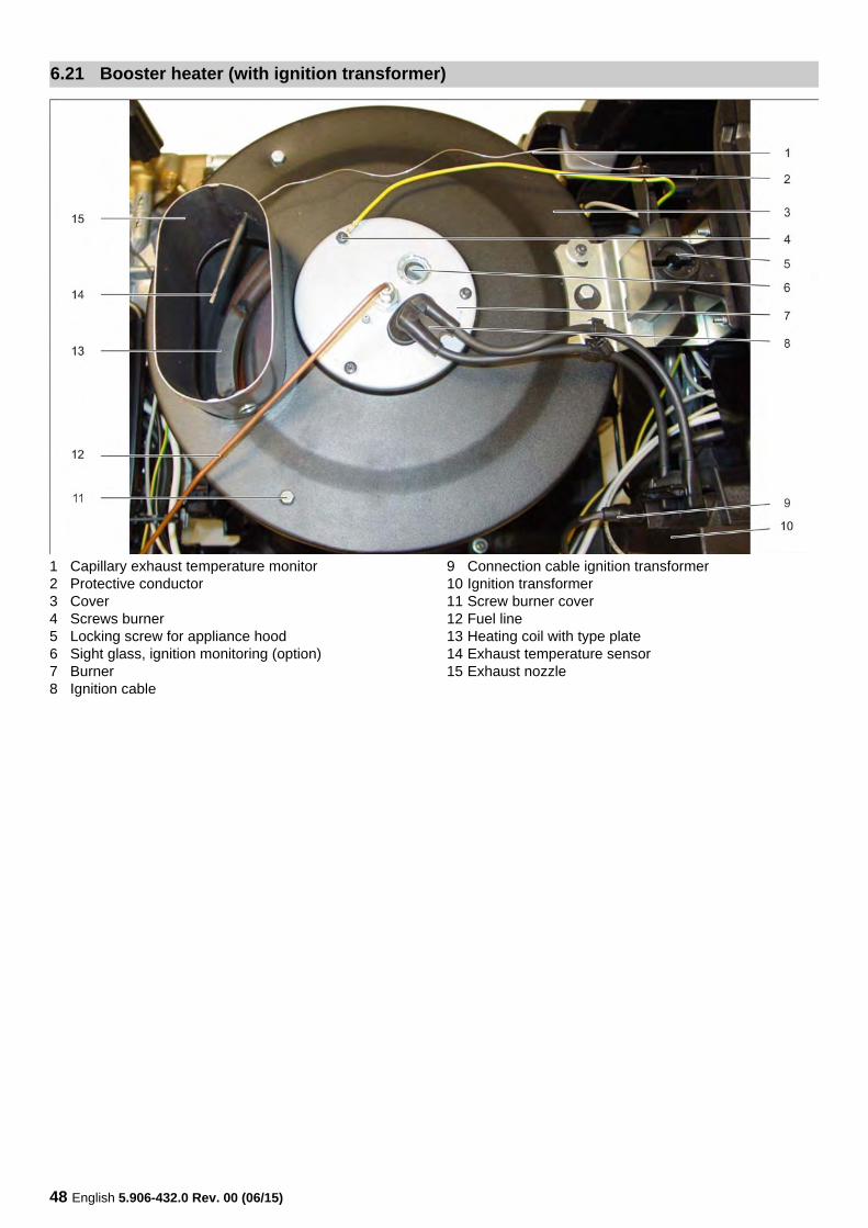
1 Capillary exhaust temperature monitor2 Protective conductor3 Cover4 Screws burner5 Locking screw for appliance hood6 Sight glass, ignition monitoring (option)7 Burner8 Ignition cable
9 Connection cable ignition transformer10 Ignition transformer11 Screw burner cover12 Fuel line13 Heating coil with type plate14 Exhaust temperature sensor15 Exhaust nozzle
6.21 Booster heater (with ignition transformer)
English 5.906-432.0 Rev. 00 (06/15) 49
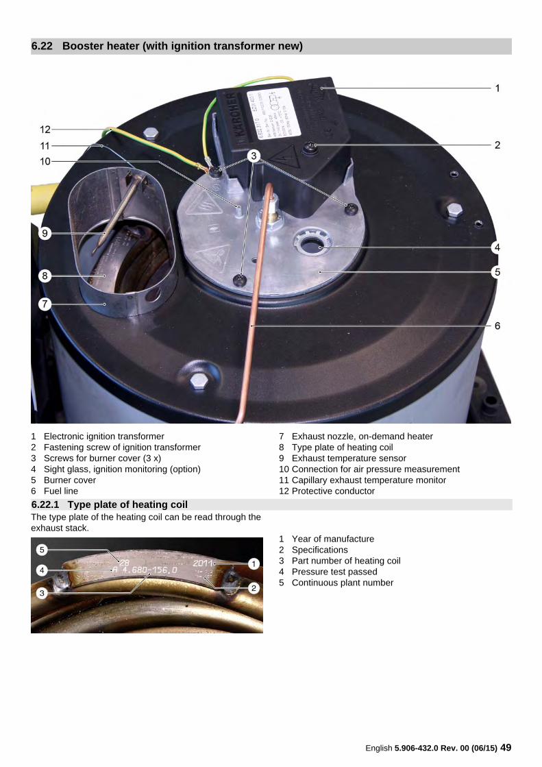
1 Electronic ignition transformer2 Fastening screw of ignition transformer3 Screws for burner cover (3 x)4 Sight glass, ignition monitoring (option)5 Burner cover6 Fuel line
7 Exhaust nozzle, on-demand heater8 Type plate of heating coil9 Exhaust temperature sensor10 Connection for air pressure measurement11 Capillary exhaust temperature monitor12 Protective conductor
The type plate of the heating coil can be read through the exhaust stack.
1 Year of manufacture2 Specifications3 Part number of heating coil4 Pressure test passed5 Continuous plant number
6.22 Booster heater (with ignition transformer new)
6.22.1 Type plate of heating coil
50 English 5.906-432.0 Rev. 00 (06/15)
Various ignition transformers are installed in the devices.
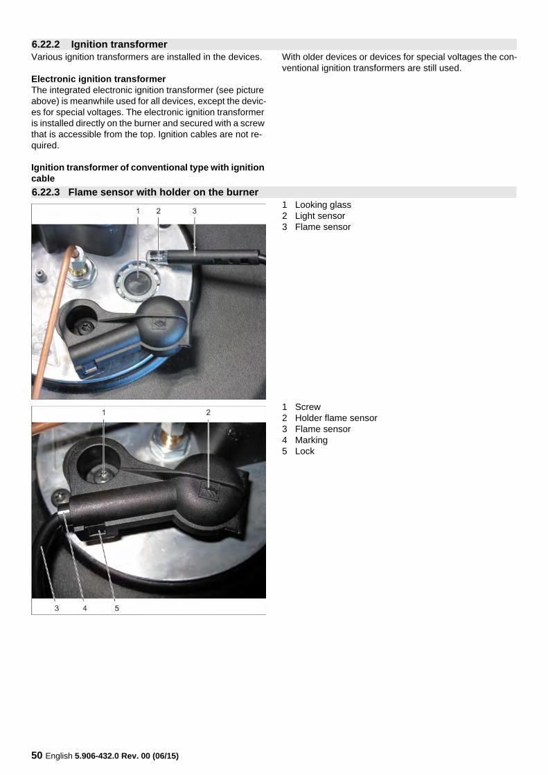
Electronic ignition transformerThe integrated electronic ignition transformer (see picture above) is meanwhile used for all devices, except the devic-es for special voltages. The electronic ignition transformer is installed directly on the burner and secured with a screw that is accessible from the top. Ignition cables are not re-quired.
Ignition transformer of conventional type with ignition cable
With older devices or devices for special voltages the con-ventional ignition transformers are still used.
1 Looking glass2 Light sensor3 Flame sensor
1 Screw2 Holder flame sensor3 Flame sensor4 Marking5 Lock
6.22.2 Ignition transformer
6.22.3 Flame sensor with holder on the burner
English 5.906-432.0 Rev. 00 (06/15) 51
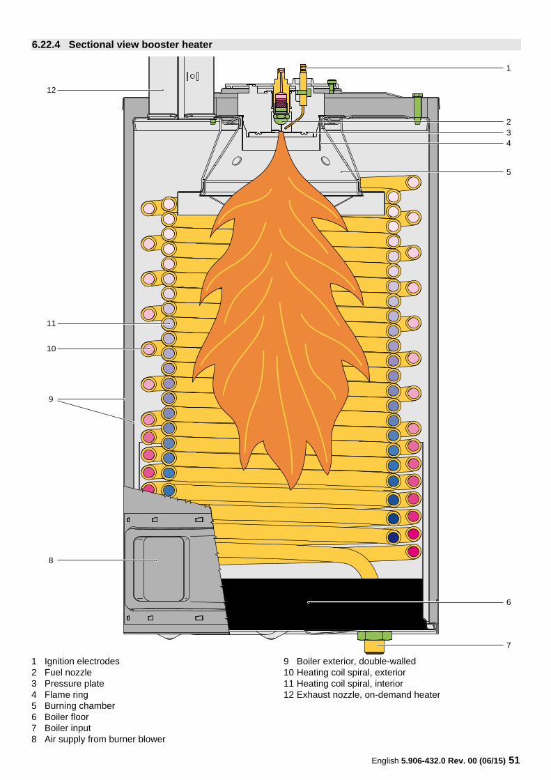
1 Ignition electrodes2 Fuel nozzle3 Pressure plate4 Flame ring5 Burning chamber6 Boiler floor7 Boiler input8 Air supply from burner blower
9 Boiler exterior, double-walled10 Heating coil spiral, exterior11 Heating coil spiral, interior12 Exhaust nozzle, on-demand heater
6.22.4 Sectional view booster heater
1
10
234
5
6
7
12
11
9
8
52 English 5.906-432.0 Rev. 00 (06/15)
Mode of operationThe water from the high pressure pump enters the interior heating coil spiral, is heated while flowing through and ex-its to the bottom from the heating coil spiral.The fuel is vaporised by the fuel nozzle and ignited by the spark of the ignition electrodes.The combustion air from the blower first flows through the double-walled boiler exterior toward the top, then it flows downward with the flame and is emitted as exhaust through the exhaust stack toward the top into the atmos-phere.The boiler floor is made of fire-resistant insulating con-crete. It prevents a radiation of the heat and is used to re-route the flames.The adjustment of the burner to good exhaust values is achieved via the air flap on the blower (air volume) and with the adjustment screw on the fuel pump (fuel pres-sure).The temperature increase with the full water volume is 60-65 K independent of the device.If the water volume is reduced via the pressure and volume control, the water can be heated to approx. 100 °C; if you use the steam nozzle, up to 155 °C.An optimal burner performance is only possible if the heat-ing coil is neither full of soot nor other deposits.Furthermore, the spark electrodes, the amount of fuel and the amount of air must be adjusted properly.Steam operationThe following preparations must be made for steam oper-ation:– Install steam nozzle– Set the operating pressure on the pressure and volume
control on the pump to the lowest value– Set the desired steam temperature at the operating
panel
NoteAs per pressure device guidelines, the operating pressure inside the appliance must be less than 32 bars for steam operation.This is ensured by reducing the operating pressure on the pressure and volume control and by using the supplied steam nozzle.
English 5.906-432.0 Rev. 00 (06/15) 53
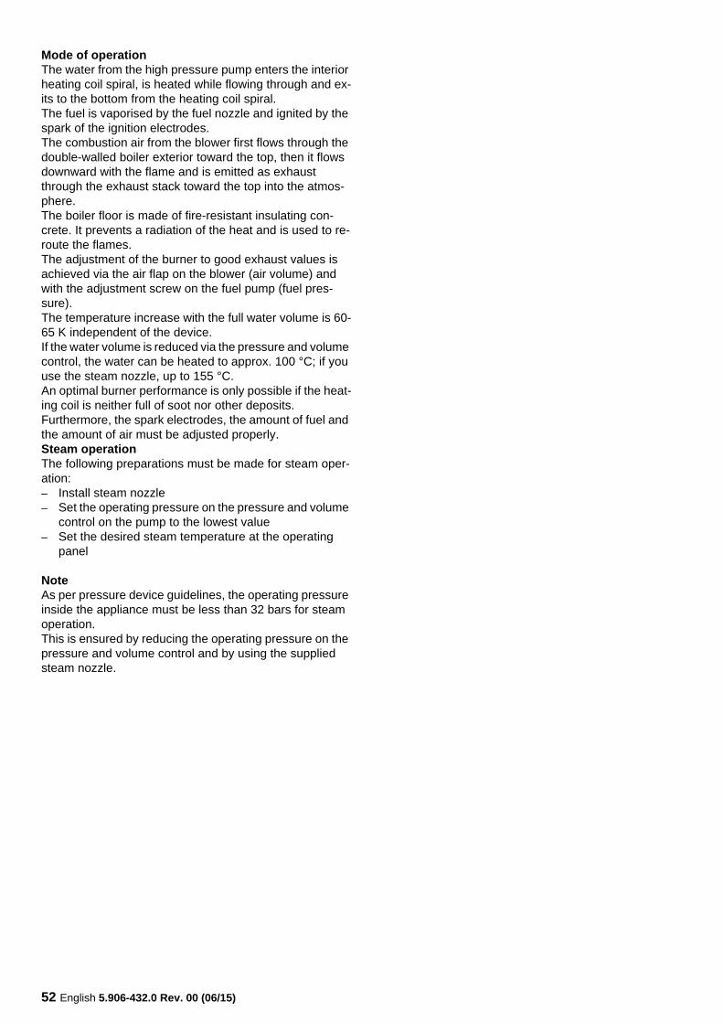
1 Looking glass2 Connection pressure line3 Connection ignition electrode4 Connection for air pressure measurement5 Burner cover
1 Ignition electrode2 Fuel nozzle3 Pressure plate
1 Ignition electrode2 Fuel nozzle
6.23 Burner
54 English 5.906-432.0 Rev. 00 (06/15)
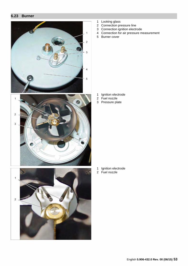
1 Ignition electrodes2 Fuel nozzle holder3 Fuel nozzle4 Spray angle 45° or 60°, depending on the type of appli-
ance5 Screw6 Burner coverBurnerThere is a strong spark created between the two ignition electrodes to ensure that the injected fuel will ignite.The necessary ignition voltage is generated by the ignition transformer.The exact adherence to the adjustment dimensions is a basic requirement for the proper function of the burner, for good exhaust values and the long idle time of the ignition electrodes.There is always a ignition spark between the two ignition electrodes, during cold and hot water operation (continu-ous ignition).This is a safety measure, so that injected fuel will be ignited in any case and cannot accumulate unburned in the on-de-mand heater (deflagration hazard).
6.24 Burner
English 5.906-432.0 Rev. 00 (06/15) 55
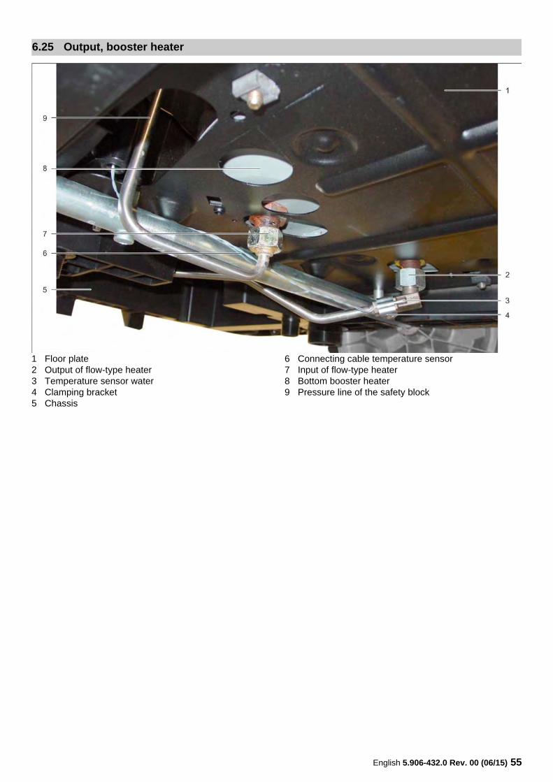
1 Floor plate2 Output of flow-type heater3 Temperature sensor water4 Clamping bracket5 Chassis
6 Connecting cable temperature sensor7 Input of flow-type heater8 Bottom booster heater9 Pressure line of the safety block
6.25 Output, booster heater
56 English 5.906-432.0 Rev. 00 (06/15)
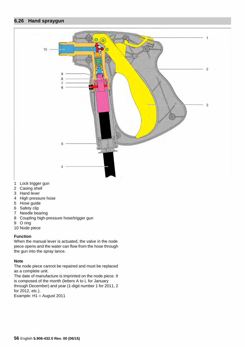
1 Lock trigger gun2 Casing shell3 Hand lever4 High pressure hose5 Hose guide6 Safety clip7 Needle bearing8 Coupling high-pressure hose/trigger gun9 O ring10 Node piece
FunctionWhen the manual lever is actuated, the valve in the node piece opens and the water can flow from the hose through the gun into the spray lance.
NoteThe node piece cannot be repaired and must be replaced as a complete unit.The date of manufacture is imprinted on the node piece. It is composed of the month (letters A to L for January through December) and year (1-digit number 1 for 2011, 2 for 2012, etc.).Example: H1 = August 2011
6.26 Hand spraygun
English 5.906-432.0 Rev. 00 (06/15) 57
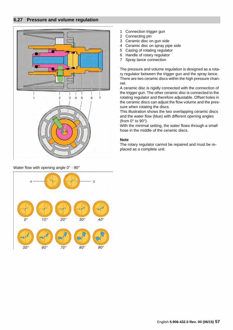
1 Connection trigger gun2 Connecting pin3 Ceramic disc on gun side4 Ceramic disc on spray pipe side5 Casing of rotating regulator6 Handle of rotary regulator7 Spray lance connection
The pressure and volume regulation is designed as a rota-ry regulator between the trigger gun and the spray lance.There are two ceramic discs within the high pressure chan-nel.A ceramic disc is rigidly connected with the connection of the trigger gun. The other ceramic disc is connected to the rotating regulator and therefore adjustable. Offset holes in the ceramic discs can adjust the flow volume and the pres-sure when rotating the discs.This illustration shows the two overlapping ceramic discs and the water flow (blue) with different opening angles (from 0° to 90°).With the minimal setting, the water flows through a small hose in the middle of the ceramic discs.
NoteThe rotary regulator cannot be repaired and must be re-placed as a complete unit.
Water flow with opening angle 0° - 90°
6.27 Pressure and volume regulation
58 English 5.906-432.0 Rev. 00 (06/15)
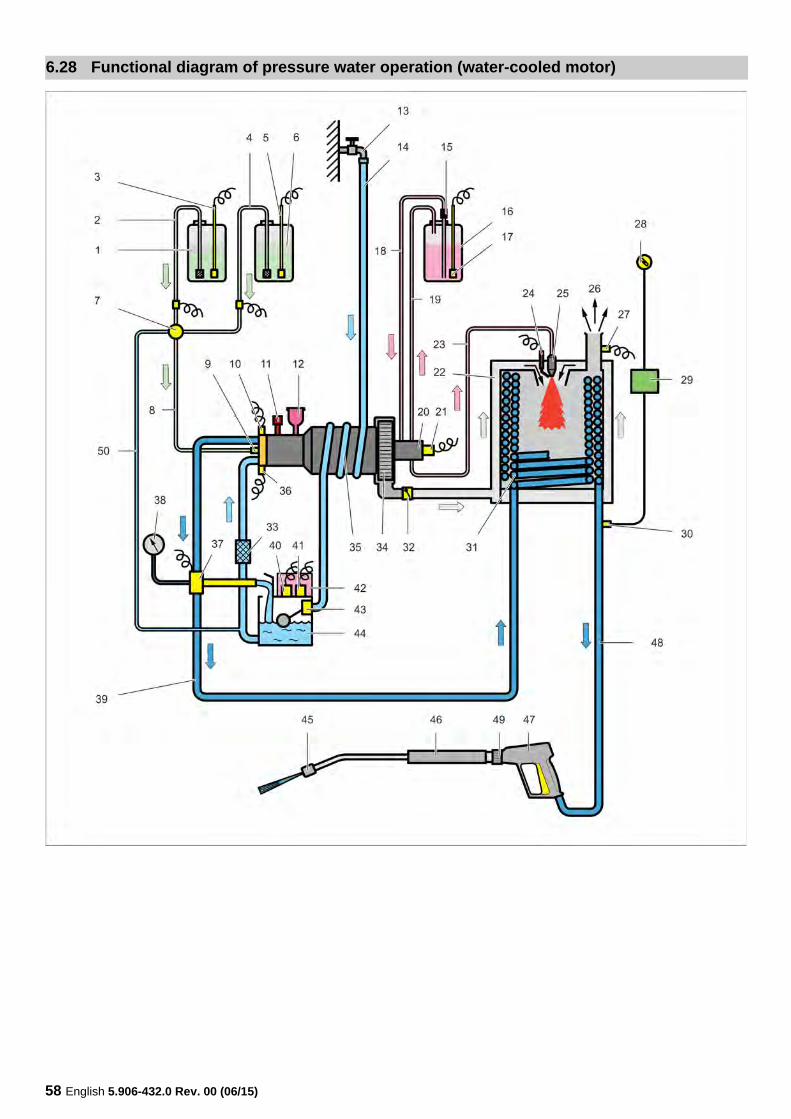
6.28 Functional diagram of pressure water operation (water-cooled motor)
English 5.906-432.0 Rev. 00 (06/15) 59
1 Detergent tank 1, volume 10 l2 Detergent suction hose with filter3 Level sensor, detergent tank 1 (option)4 Detergent suction hose with filter5 Level sensor, detergent tank 2 (option)6 Detergent tank 2, volume 20 l7 Dosage valve for detergent8 Suction hose for detergent9 Detergent check valve10 Pressure switch ON11 Pressure and volume regulation12 Oil tank13 Water connection14 Water supply hose15 Fuel filter16 Fuel tank17 Level sensor for fuel tank18 Fuel suction hose19 Fuel return line20 Fuel pump21 Solenoid valve, fuel pump22 Continuous heater23 Fuel pressure line24 Ignition electrodes25 Fuel nozzle26 Exhaust nozzle
27 Exhaust temperature sensor28 Setting, water temperature29 Printed circuit board (PCB)30 Temperature sensor31 Heating coil32 Air flap33 Water fine filter34 Burner blower35 Motor casing with cooling coil36 Pressure switch OFF37 Safety block with water shortage safeguard and safety
valve38 Manometer39 Pressure pipe40 Solenoid valve liquid softener41 Level sensor liquid softener42 Liquid softener reservoir43 Swimmer valve44 Float tank45 High pressure nozzle46 Spray lance47 Trigger gun48 High pressure hose49 Rotary regulator for pressure and quantity regulation 50 Rinse line
60 English 5.906-432.0 Rev. 00 (06/15)
6.29 Functional diagram vacuuming operation
English 5.906-432.0 Rev. 00 (06/15) 61
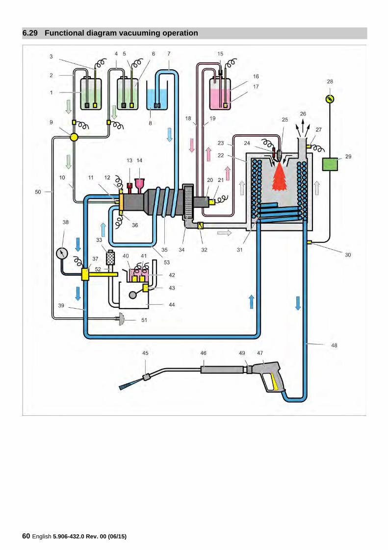
1 Detergent tank 12 Detergent suction hose with filter3 Level sensor, detergent tank 14 Detergent suction hose with filter5 Level sensor, detergent tank 26 Detergent tank 27 Suction hose with filter and check valve8 Open container9 Dosage valve for detergent10 Suction hose for detergent11 Detergent check valve12 Pressure switch ON13 Pressure and volume regulation14 Oil tank15 Fuel filter16 Fuel tank17 Level sensor for fuel tank18 Fuel suction hose19 Fuel return line20 Fuel pump21 Solenoid valve, fuel pump22 Continuous heater23 Fuel pressure line24 Ignition electrodes25 Fuel nozzle26 Exhaust nozzle27 Exhaust temperature sensor28 Setting, water temperature29 Printed circuit board (PCB)30 Temperature sensor31 Heating coil32 Air flap33 Water fine filter34 Burner blower35 Motor casing with cooling coil36 Pressure switch OFF37 Safety block with water shortage safeguard and safety
valve38 Manometer39 Pressure pipe40 Solenoid valve liquid softener41 Level sensor liquid softener42 Liquid softener reservoir43 Swimmer valve44 Float tank45 High pressure nozzle46 Spray lance47 Trigger gun48 High pressure hose49 Rotary regulator for pressure and quantity regulation 50 Rinse line51 Slot (plug) vacuuming operations52 Hose to the fine filter53 Hose from the motor cooling to the pump
NoteDuring vacuuming operations, the float container must be bypassed.
62 English 5.906-432.0 Rev. 00 (06/15)
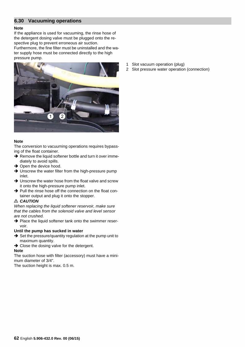
NoteIf the appliance is used for vacuuming, the rinse hose of the detergent dosing valve must be plugged onto the re-spective plug to prevent erroneous air suction.Furthermore, the fine filter must be uninstalled and the wa-ter supply hose must be connected directly to the high pressure pump.
1 Slot vacuum operation (plug)2 Slot pressure water operation (connection)
NoteThe conversion to vacuuming operations requires bypass-ing of the float container. Remove the liquid softener bottle and turn it over imme-
diately to avoid spills. Open the device hood. Unscrew the water filter from the high-pressure pump
inlet. Unscrew the water hose from the float valve and screw
it onto the high-pressure pump inlet. Pull the rinse hose off the connection on the float con-
tainer output and plug it onto the stopper.� CAUTIONWhen replacing the liquid softener reservoir, make sure that the cables from the solenoid valve and level sensor are not crushed. Place the liquid softener tank onto the swimmer reser-
voir.Until the pump has sucked in water Set the pressure/quantity regulation at the pump unit to
maximum quantity. Close the dosing valve for the detergent.NoteThe suction hose with filter (accessory) must have a mini-mum diameter of 3/4".The suction height is max. 0.5 m.
6.30 Vacuuming operations
English 5.906-432.0 Rev. 00 (06/15) 63
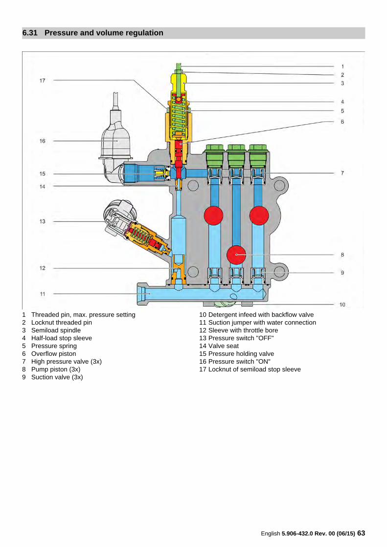
1 Threaded pin, max. pressure setting2 Locknut threaded pin3 Semiload spindle4 Half-load stop sleeve5 Pressure spring6 Overflow piston7 High pressure valve (3x)8 Pump piston (3x)9 Suction valve (3x)
10 Detergent infeed with backflow valve11 Suction jumper with water connection12 Sleeve with throttle bore13 Pressure switch "OFF"14 Valve seat15 Pressure holding valve16 Pressure switch "ON"17 Locknut of semiload stop sleeve
6.31 Pressure and volume regulation
64 English 5.906-432.0 Rev. 00 (06/15)
Manually with a pressure regulator on the high pres-sure pumpThe pressure and volume regulation via the handle on the high pressure pump is used to relieve the motor with most-ly partial load operation.Turning the spindle anticlockwise lowers the pretension of the pressure spring.This will lift the overflow piston with a lower pressure from the valve seat and part of the flowing volume runs to the suction chamber via the sleeve with the throttle bore.The pump runs at reduced pressure.Depending on the spindle setting, the pressure and the water volume change.
With the rotary regulator on the gunThe pressure and volume regulation via the rotary regula-tor on the gun should only be used during occasional par-tial load operation.When the pressure is reduced via the rotary regulator, the manual pressure and volume regulation on the pump must always be opened all the way (direction "+" on the handle); otherwise, the appliance will shut off prematurely.If the rotary regulator is partially closed, the pressure in the system will increase.This will lift the piston off the valve seat so that a part of the flowing volume flows back to the suction chamber via the return.The pump continues to run at high pressure.Depending on the setting of the rotary regulator on the gun, the pressure and the water volume change.Gun closedIf the gun is closed completely, the piston will open all the way and the entire flow volume of the pump flows to the suction chamber via the throttle bore.The dynamic pressure building up through the throttle bore of the sleeve in the return actuates the pressure switch which will in turn shut off the appliance.
6.31.1 Function pressure and volume regulation
English 5.906-432.0 Rev. 00 (06/15) 65
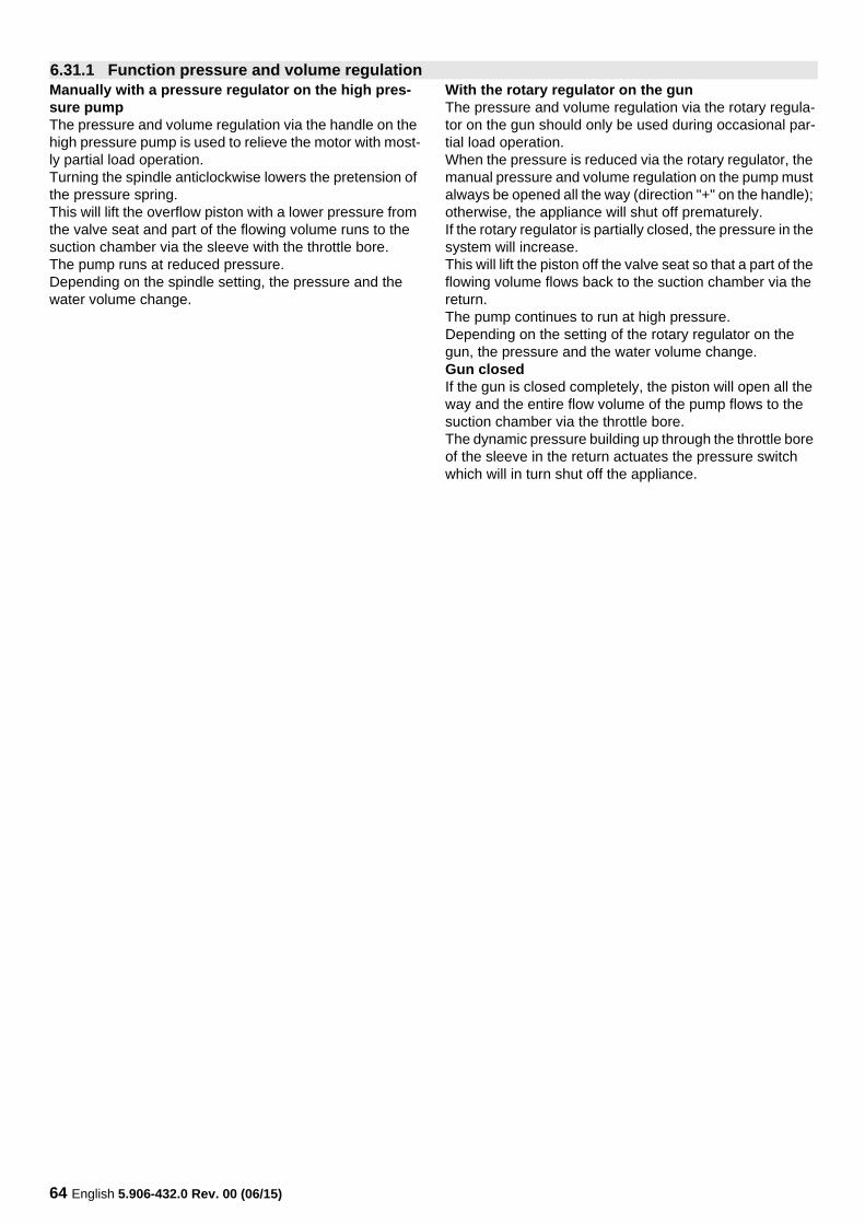
1 High pressure outlet (without pressure)2 Manometer (without pressure)3 Pressure retaining valve (closed)4 Pump stands still5 Rotary knob6 Overflow valve (closed)7 Reduction bore8 Pressure switch "OFF" (closed)9 Water inlet10 Motor contactors (K1) (open)11 Pressure switch "ON" (closed)
NoteThe shown functions of the preessure switches and motor contactor are for understanding purposes only.In reality, the information from the two pressure switches is transferred directly to the control electronics, which in turn controls the motor contactor.
When the appliance is switched off and the gun is open, the pressure is taken from the system and it is without volt-age.Both pressure switches as well as the overflow valve and the pressure retaining valve closed.The motor contactors are open.
6.32 Functional description of pressure switch
6.32.1 Appliance is switched off
0 Volt
6
1 3 4
7
8
9
11
5
10
2
66 English 5.906-432.0 Rev. 00 (06/15)
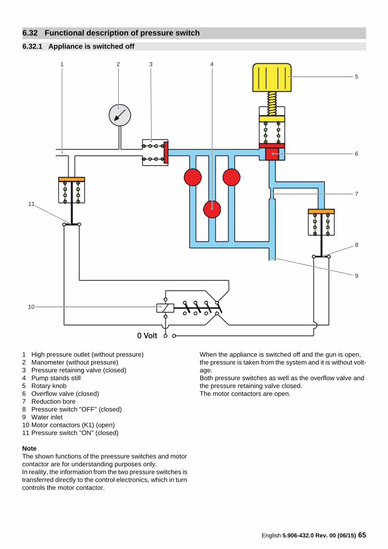
1 High pressure outlet, working pressure2 Manometer, working pressure3 Pressure retaining valve (open)4 Pump is running5 Rotary knob6 Overflow valve (closed)7 Reduction bore8 Pressure switch "OFF" (closed)9 Water inlet10 Motor contactors (K1) (closed)11 Pressure switch "ON" (open)
NoteThe shown functions of the preessure switches and motor contactor are for understanding purposes only.In reality, the information from the two pressure switches is transferred directly to the control electronics, which in turn controls the motor contactor.
After switching on the appliance and with the gun open, the contactor will be actuated and closes the contacts.This will start the motor and the pump will build up the working pressure.Open the pressure retaining valve and the pressure switch "ON", the overflow valve and the pressure switch "OFF" re-main closed.Due to the closed pressure swtich, the motor contactors also remain closed.
6.32.2 The appliance is switched on and the gun is open
24 Volt
6
1 3 4
7
8
9
11
5
10
2
English 5.906-432.0 Rev. 00 (06/15) 67
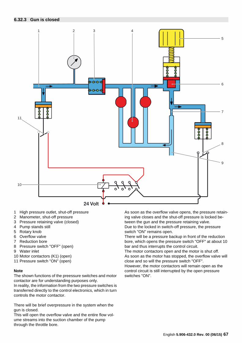
1 High pressure outlet, shut-off pressure2 Manometer, shut-off pressure3 Pressure retaining valve (closed)4 Pump stands still5 Rotary knob6 Overflow valve7 Reduction bore8 Pressure switch "OFF" (open)9 Water inlet10 Motor contactors (K1) (open)11 Pressure switch "ON" (open)
NoteThe shown functions of the preessure switches and motor contactor are for understanding purposes only.In reality, the information from the two pressure switches is transferred directly to the control electronics, which in turn controls the motor contactor.
There will be brief overpressure in the system when the gun is closed.This will open the overflow valve and the entire flow vol-ume streams into the suction chamber of the pump through the throttle bore.
As soon as the overflow valve opens, the pressure retain-ing valve closes and the shut-off pressure is locked be-tween the gun and the pressure retaining valve.Due to the locked in switch-off pressure, the pressure switch "ON" remains open.There will be a pressure backup in front of the reduction bore, which opens the pressure switch "OFF" at about 10 bar and thus interrupts the control circuit.The motor contactors open and the motor is shut off.As soon as the motor has stopped, the overflow valve will close and so will the pressure switch "OFF".However, the motor contactors will remain open as the control circuit is still interrupted by the open pressure switches "ON".
6.32.3 Gun is closed
24 Volt
6
1 3 4
7
8
9
11
5
10
2
68 English 5.906-432.0 Rev. 00 (06/15)
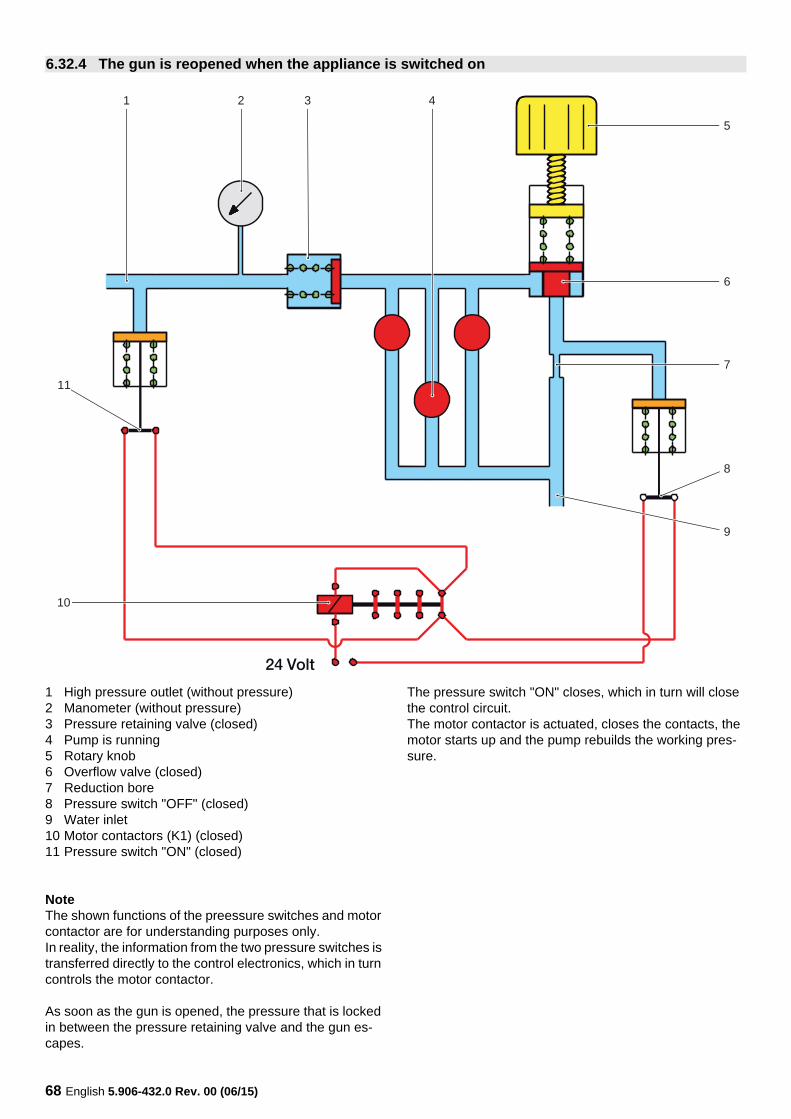
1 High pressure outlet (without pressure)2 Manometer (without pressure)3 Pressure retaining valve (closed)4 Pump is running5 Rotary knob6 Overflow valve (closed)7 Reduction bore8 Pressure switch "OFF" (closed)9 Water inlet10 Motor contactors (K1) (closed)11 Pressure switch "ON" (closed)
NoteThe shown functions of the preessure switches and motor contactor are for understanding purposes only.In reality, the information from the two pressure switches is transferred directly to the control electronics, which in turn controls the motor contactor.
As soon as the gun is opened, the pressure that is locked in between the pressure retaining valve and the gun es-capes.
The pressure switch "ON" closes, which in turn will close the control circuit.The motor contactor is actuated, closes the contacts, the motor starts up and the pump rebuilds the working pres-sure.
6.32.4 The gun is reopened when the appliance is switched on
24 Volt
6
1 3 4
7
8
9
11
5
10
2
English 5.906-432.0 Rev. 00 (06/15) 69
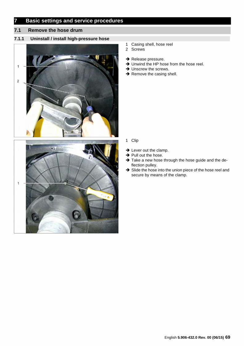
1 Casing shell, hose reel2 Screws
Release pressure. Unwind the HP hose from the hose reel. Unscrew the screws. Remove the casing shell.
1 Clip
Lever out the clamp. Pull out the hose. Take a new hose through the hose guide and the de-
flection pulley. Slide the hose into the union piece of the hose reel and
secure by means of the clamp.
7 Basic settings and service procedures
7.1 Remove the hose drum
7.1.1 Uninstall / install high-pressure hose
70 English 5.906-432.0 Rev. 00 (06/15)
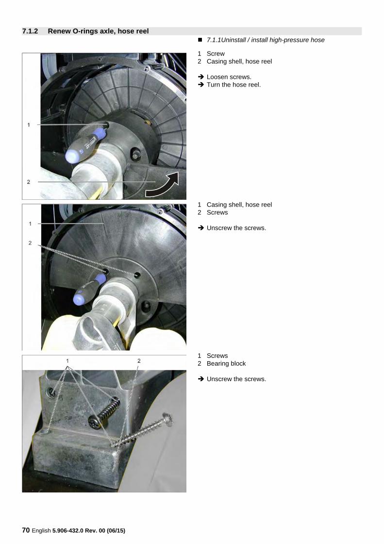
7.1.1Uninstall / install high-pressure hose
1 Screw2 Casing shell, hose reel
Loosen screws. Turn the hose reel.
1 Casing shell, hose reel2 Screws
Unscrew the screws.
1 Screws2 Bearing block
Unscrew the screws.
7.1.2 Renew O-rings axle, hose reel
English 5.906-432.0 Rev. 00 (06/15) 71
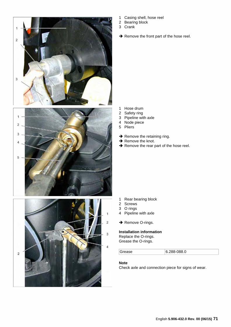
1 Casing shell, hose reel2 Bearing block3 Crank
Remove the front part of the hose reel.
1 Hose drum2 Safety ring3 Pipeline with axle4 Node piece5 Pliers
Remove the retaining ring. Remove the knot. Remove the rear part of the hose reel.
1 Rear bearing block2 Screws3 O rings4 Pipeline with axle
Remove O-rings.
Installation informationReplace the O-rings.Grease the O-rings.
NoteCheck axle and connection piece for signs of wear.
Grease 6.288-088.0
72 English 5.906-432.0 Rev. 00 (06/15)
7.1.2Renew O-rings axle, hose reel
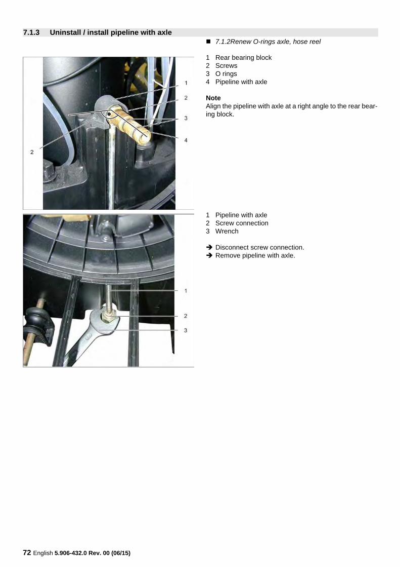
1 Rear bearing block2 Screws3 O rings4 Pipeline with axle
NoteAlign the pipeline with axle at a right angle to the rear bear-ing block.
1 Pipeline with axle2 Screw connection3 Wrench
Disconnect screw connection. Remove pipeline with axle.
7.1.3 Uninstall / install pipeline with axle
English 5.906-432.0 Rev. 00 (06/15) 73
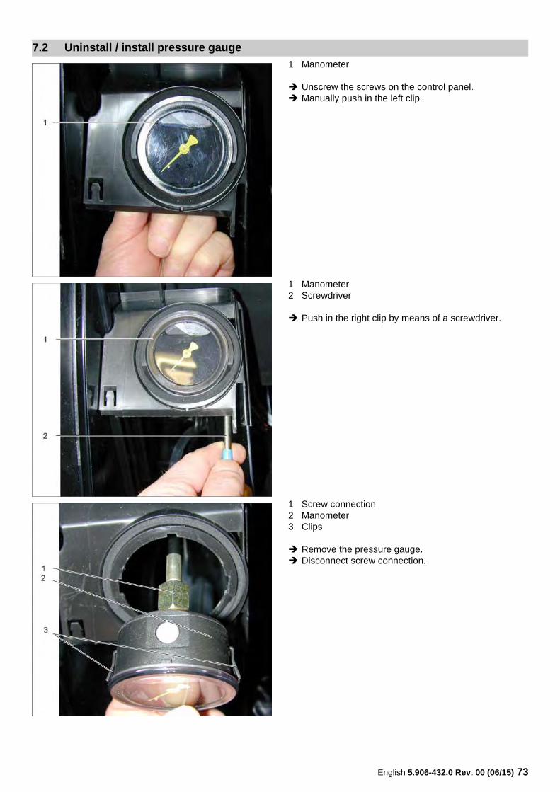
1 Manometer
Unscrew the screws on the control panel. Manually push in the left clip.
1 Manometer2 Screwdriver
Push in the right clip by means of a screwdriver.
1 Screw connection2 Manometer3 Clips
Remove the pressure gauge. Disconnect screw connection.
7.2 Uninstall / install pressure gauge
74 English 5.906-432.0 Rev. 00 (06/15)
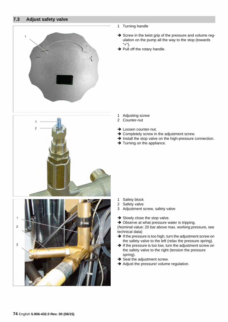
1 Turning handle
Screw in the twist grip of the pressure and volume reg-ulation on the pump all the way to the stop (towards "+").
Pull off the rotary handle.
1 Adjusting screw2 Counter-nut
Loosen counter-nut. Completely screw in the adjustment screw. Install the stop valve on the high-pressure connection. Turning on the appliance.
1 Safety block2 Safety valve3 Adjustment screw, safety valve
Slowly close the stop valve. Observe at what pressure water is tripping.(Nominal value: 20 bar above max. working pressure, see technical data) If the pressure is too high, turn the adjustment screw on
the safety valve to the left (relax the pressure spring). If the pressure is too low, turn the adjustment screw on
the safety valve to the right (tension the pressure spring).
Seal the adjustment screw. Adjust the pressure/ volume regulation.
7.3 Adjust safety valve
English 5.906-432.0 Rev. 00 (06/15) 75
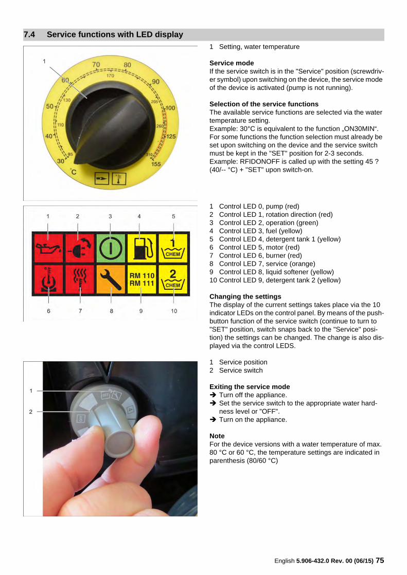
1 Setting, water temperature
Service modeIf the service switch is in the "Service" position (screwdriv-er symbol) upon switching on the device, the service mode of the device is activated (pump is not running).
Selection of the service functionsThe available service functions are selected via the water temperature setting.Example: 30°C is equivalent to the function „ON30MIN“.For some functions the function selection must already be set upon switching on the device and the service switch must be kept in the "SET" position for 2-3 seconds.Example: RFIDONOFF is called up with the setting 45 ? (40/-- °C) + "SET" upon switch-on.
1 Control LED 0, pump (red)2 Control LED 1, rotation direction (red)3 Control LED 2, operation (green)4 Control LED 3, fuel (yellow)5 Control LED 4, detergent tank 1 (yellow)6 Control LED 5, motor (red)7 Control LED 6, burner (red)8 Control LED 7, service (orange)9 Control LED 8, liquid softener (yellow)10 Control LED 9, detergent tank 2 (yellow)
Changing the settingsThe display of the current settings takes place via the 10 indicator LEDs on the control panel. By means of the push-button function of the service switch (continue to turn to "SET" position, switch snaps back to the "Service" posi-tion) the settings can be changed. The change is also dis-played via the control LEDS.
1 Service position2 Service switch
Exiting the service mode Turn off the appliance. Set the service switch to the appropriate water hard-
ness level or "OFF". Turn on the appliance.
NoteFor the device versions with a water temperature of max. 80 °C or 60 °C, the temperature settings are indicated in parenthesis (80/60 °C)
7.4 Service functions with LED display
76 English 5.906-432.0 Rev. 00 (06/15)
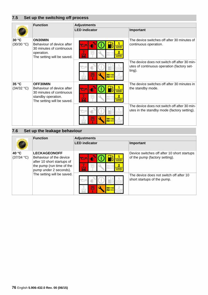
7.5 Set up the switching off process
Function Adjustments
LED indicator Important
30 °C(30/30 °C)
ON30MINBehaviour of device after 30 minutes of continuous operation.The setting will be saved.
The device switches off after 30 minutes of continuous operation.
The device does not switch off after 30 min-utes of continuous operation (factory set-ting).
35 °C(34/32 °C)
OFF30MINBehaviour of device after 30 minutes of continuous standby operation.The setting will be saved.
The device switches off after 30 minutes in the standby mode.
The device does not switch off after 30 min-utes in the standby mode (factory setting).
7.6 Set up the leakage behaviour
Function Adjustments
LED indicator Important
40 °C(37/34 °C)
LECKAGEONOFFBehaviour of the device after 10 short startups of the pump (run time of the pump under 2 seconds).The setting will be saved.
Device switches off after 10 short startups of the pump (factory setting).
The device does not switch off after 10 short startups of the pump.
English 5.906-432.0 Rev. 00 (06/15) 77
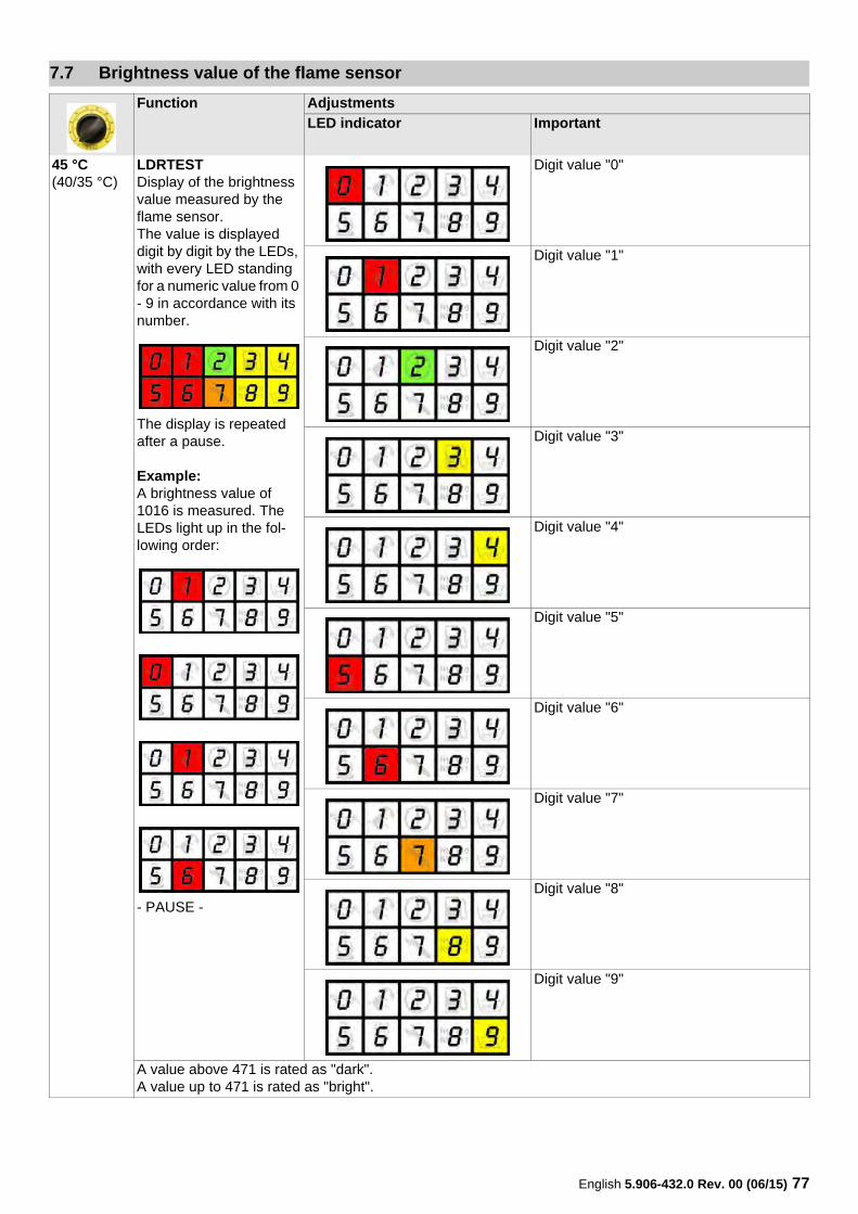
7.7 Brightness value of the flame sensor
Function Adjustments
LED indicator Important
45 °C(40/35 °C)
LDRTESTDisplay of the brightness value measured by the flame sensor.The value is displayed digit by digit by the LEDs, with every LED standing for a numeric value from 0 - 9 in accordance with its number.
The display is repeated after a pause.
Example:A brightness value of 1016 is measured. The LEDs light up in the fol-lowing order:
- PAUSE -
Digit value "0"
Digit value "1"
Digit value "2"
Digit value "3"
Digit value "4"
Digit value "5"
Digit value "6"
Digit value "7"
Digit value "8"
Digit value "9"
A value above 471 is rated as "dark".A value up to 471 is rated as "bright".
78 English 5.906-432.0 Rev. 00 (06/15)
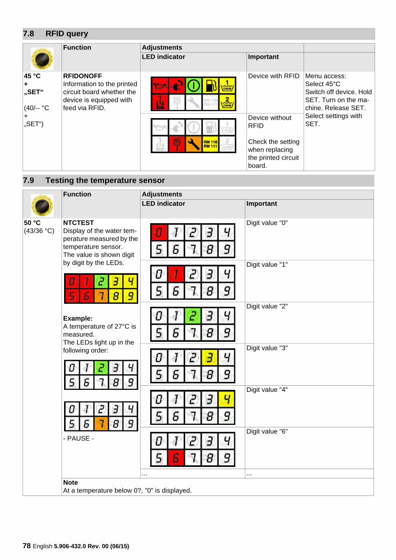
7.8 RFID query
Function Adjustments
LED indicator Important
45 °C+„SET“
(40/-- °C+„SET“)
RFIDONOFFInformation to the printed circuit board whether the device is equipped with feed via RFID.
Device with RFID Menu access:Select 45°CSwitch off device. Hold SET. Turn on the ma-chine. Release SET. Select settings with SET.
Device without RFID
Check the setting when replacing the printed circuit board.
7.9 Testing the temperature sensor
Function Adjustments
LED indicator Important
50 °C(43/36 °C)
NTCTESTDisplay of the water tem-perature measured by the temperature sensor.The value is shown digit by digit by the LEDs.
Example:A temperature of 27°C is measured.The LEDs light up in the following order:
- PAUSE -
Digit value "0"
Digit value "1"
Digit value "2"
Digit value "3"
Digit value "4"
Digit value "6"
... ...
NoteAt a temperature below 0?, "0" is displayed.
English 5.906-432.0 Rev. 00 (06/15) 79
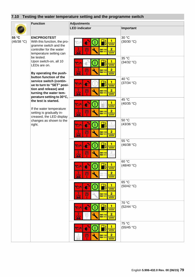
7.10 Testing the water temperature setting and the programme switch
Function Adjustments
LED indicator Important
55 °C(46/38 °C)
ENCPROGTESTWith this function, the pro-gramme switch and the controller for the water temperature setting can be tested.Upon switch-on, all 10 LEDs are on.
By operating the push-button function of the service switch (contin-ue to turn to "SET" posi-tion and release) and turning the water tem-perature setting to 30°C, the test is started.
If the water temperature setting is gradually in-creased, the LED display changes as shown to the right.
30 °C(30/30 °C)
35 °C(34/32 °C)
40 °C(37/34 °C)
45 °C(40/35 °C)
50 °C(43/36 °C)
55 °C(46/38 °C)
60 °C(48/40 °C)
65 °C(50/42 °C)
70 °C(52/44 °C)
75 °C(55/45 °C)
80 English 5.906-432.0 Rev. 00 (06/15)
Function Adjustments
LED indicator Important
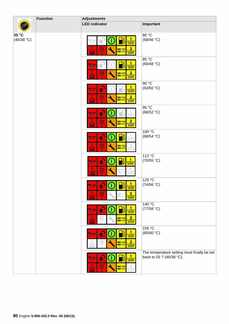
55 °C(46/38 °C)
80 °C(58/46 °C)
85 °C(60/48 °C)
90 °C(63/50 °C)
95 °C(66/52 °C)
100 °C(68/54 °C)
112 °C(70/55 °C)
125 °C(74/56 °C)
140 °C(77/58 °C)
155 °C(80/60 °C)
The temperature setting must finally be set back to 55 ? (46/38 °C).
English 5.906-432.0 Rev. 00 (06/15) 81
Function Adjustments
LED indicator Important
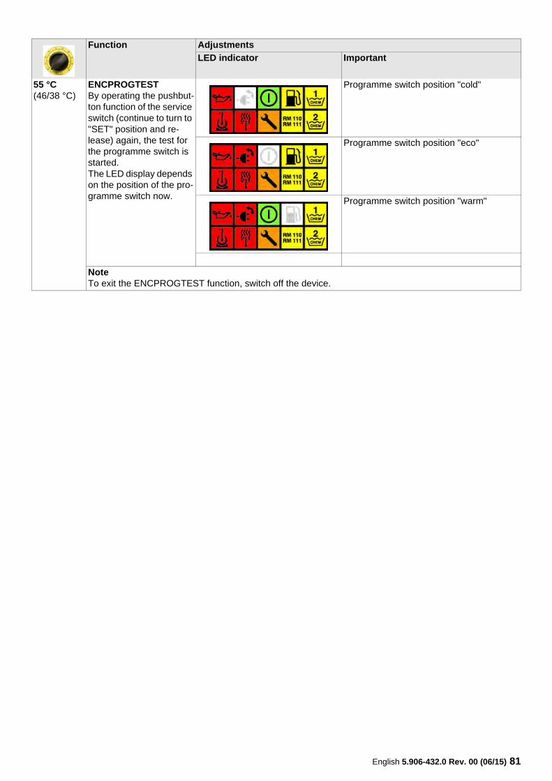
55 °C(46/38 °C)
ENCPROGTESTBy operating the pushbut-ton function of the service switch (continue to turn to "SET" position and re-lease) again, the test for the programme switch is started.The LED display depends on the position of the pro-gramme switch now.
Programme switch position "cold"
Programme switch position "eco"
Programme switch position "warm"
NoteTo exit the ENCPROGTEST function, switch off the device.
82 English 5.906-432.0 Rev. 00 (06/15)
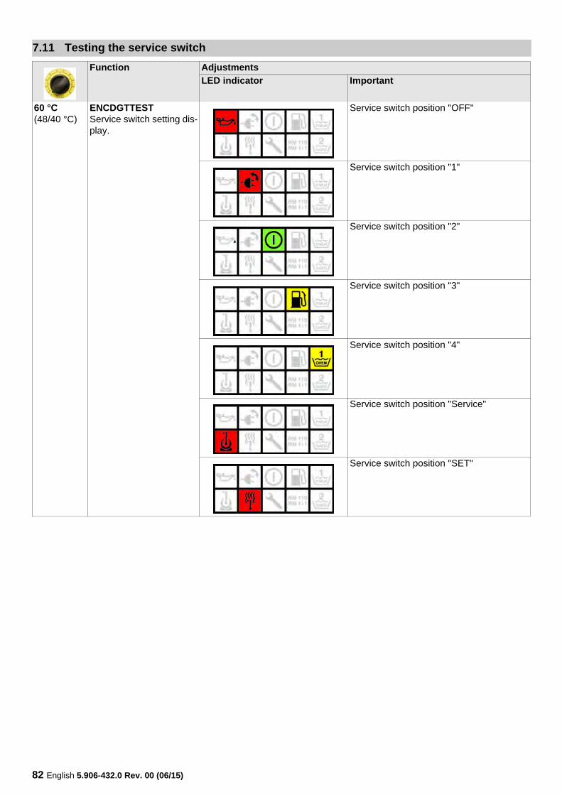
7.11 Testing the service switch
Function Adjustments
LED indicator Important
60 °C(48/40 °C)
ENCDGTTESTService switch setting dis-play.
Service switch position "OFF"
Service switch position "1"
Service switch position "2"
Service switch position "3"
Service switch position "4"
Service switch position "Service"
Service switch position "SET"
English 5.906-432.0 Rev. 00 (06/15) 83
7.12 Testing the sensor
Function Adjustments
LED indicator Important
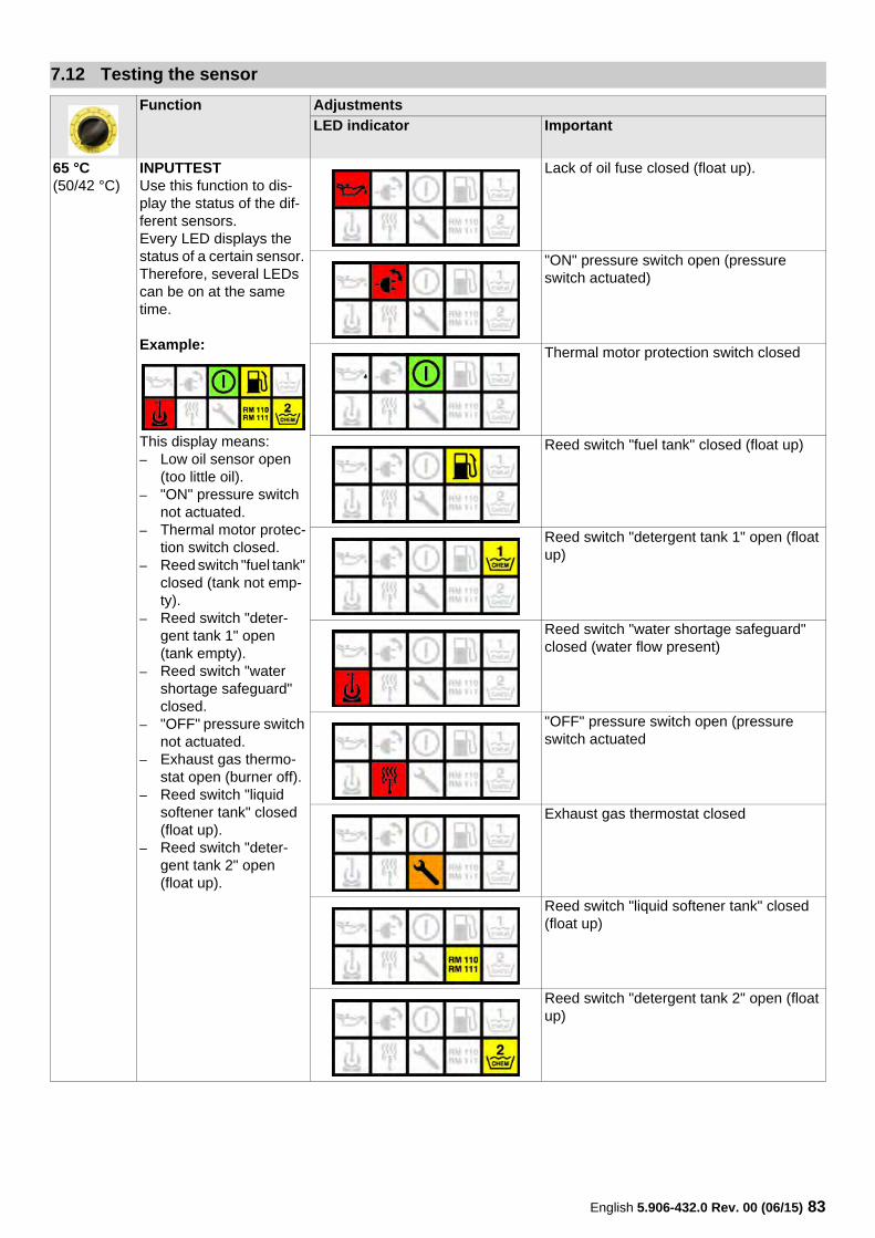
65 °C(50/42 °C)
INPUTTESTUse this function to dis-play the status of the dif-ferent sensors.Every LED displays the status of a certain sensor. Therefore, several LEDs can be on at the same time.
Example:
This display means:– Low oil sensor open
(too little oil).– "ON" pressure switch
not actuated. – Thermal motor protec-
tion switch closed.– Reed switch "fuel tank"
closed (tank not emp-ty).
– Reed switch "deter-gent tank 1" open (tank empty).
– Reed switch "water shortage safeguard" closed.
– "OFF" pressure switch not actuated.
– Exhaust gas thermo-stat open (burner off).
– Reed switch "liquid softener tank" closed (float up).
– Reed switch "deter-gent tank 2" open (float up).
Lack of oil fuse closed (float up).
"ON" pressure switch open (pressure switch actuated)
Thermal motor protection switch closed
Reed switch "fuel tank" closed (float up)
Reed switch "detergent tank 1" open (float up)
Reed switch "water shortage safeguard" closed (water flow present)
"OFF" pressure switch open (pressure switch actuated
Exhaust gas thermostat closed
Reed switch "liquid softener tank" closed (float up)
Reed switch "detergent tank 2" open (float up)
84 English 5.906-432.0 Rev. 00 (06/15)
7.13 Error memory
Function Adjustments
LED indicator Important
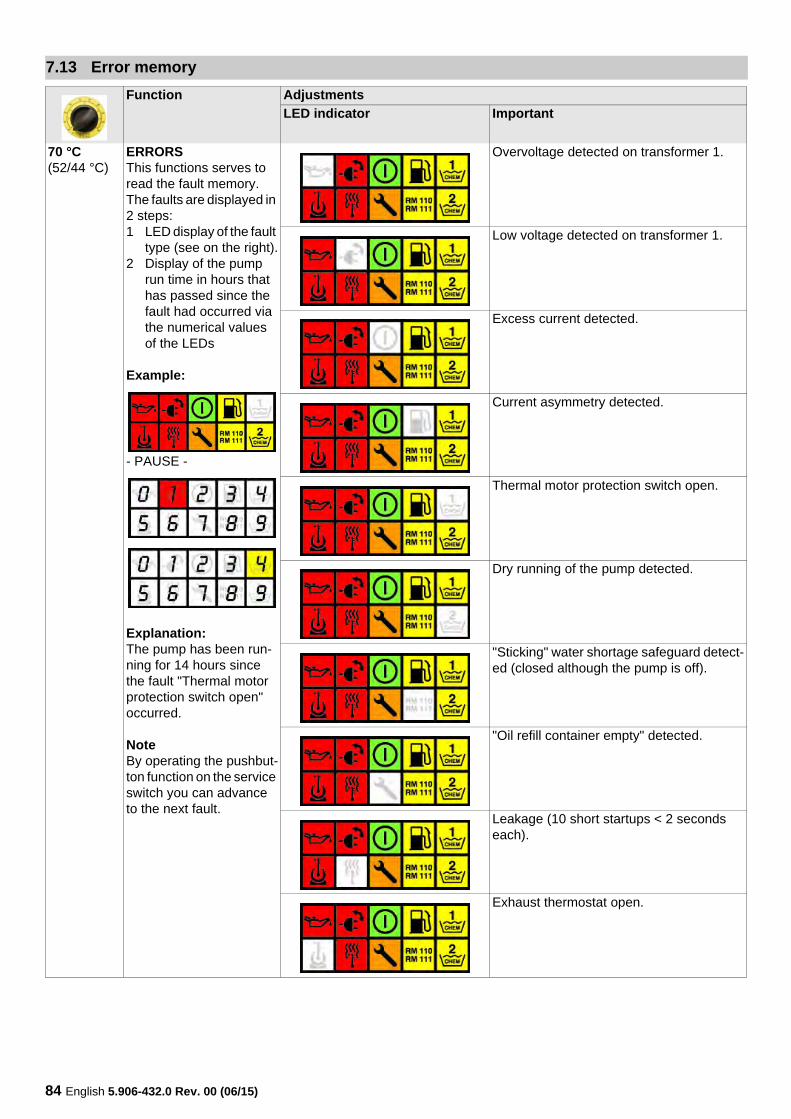
70 °C(52/44 °C)
ERRORSThis functions serves to read the fault memory.The faults are displayed in 2 steps:1 LED display of the fault
type (see on the right).2 Display of the pump
run time in hours that has passed since the fault had occurred via the numerical values of the LEDs
Example:
- PAUSE -
Explanation:The pump has been run-ning for 14 hours since the fault "Thermal motor protection switch open" occurred.
NoteBy operating the pushbut-ton function on the service switch you can advance to the next fault.
Overvoltage detected on transformer 1.
Low voltage detected on transformer 1.
Excess current detected.
Current asymmetry detected.
Thermal motor protection switch open.
Dry running of the pump detected.
"Sticking" water shortage safeguard detect-ed (closed although the pump is off).
"Oil refill container empty" detected.
Leakage (10 short startups < 2 seconds each).
Exhaust thermostat open.
English 5.906-432.0 Rev. 00 (06/15) 85
Function Adjustments
LED indicator Important
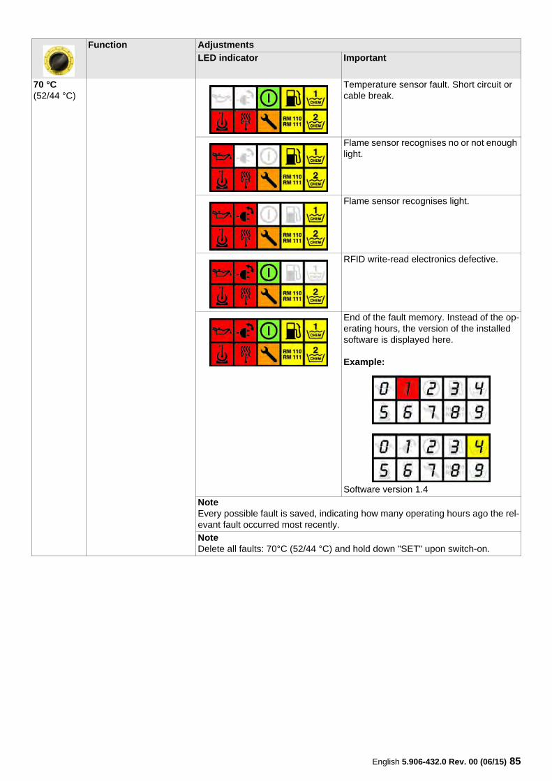
70 °C(52/44 °C)
Temperature sensor fault. Short circuit or cable break.
Flame sensor recognises no or not enough light.
Flame sensor recognises light.
RFID write-read electronics defective.
End of the fault memory. Instead of the op-erating hours, the version of the installed software is displayed here.
Example:
Software version 1.4
NoteEvery possible fault is saved, indicating how many operating hours ago the rel-evant fault occurred most recently.
NoteDelete all faults: 70°C (52/44 °C) and hold down "SET" upon switch-on.

86 English 5.906-432.0 Rev. 00 (06/15)
7.14 Operating hours
Function Adjustments
LED indicator Important
75 °C(55/45 °C)
STUNDENPWRIndication of the con-sumed RM 110/111 bot-tles.The value is displayed digit by digit by the LEDs, with every LED standing for a numeric value from 0 - 9 in accordance with its number.
The display is repeated after a pause.
Example:The device has con-sumed 42 bottles of RM 110/111.
- PAUSE -
Digit value "0"
Digit value "1"
Digit value "2"
Digit value "3"
Digit value "4"
Digit value "5"
Digit value "6"
Digit value "7"
Digit value "8"
Digit value "9"
English 5.906-432.0 Rev. 00 (06/15) 87
7.15 Gun switching operations since gun service
Function Adjustments
LED indicator Important
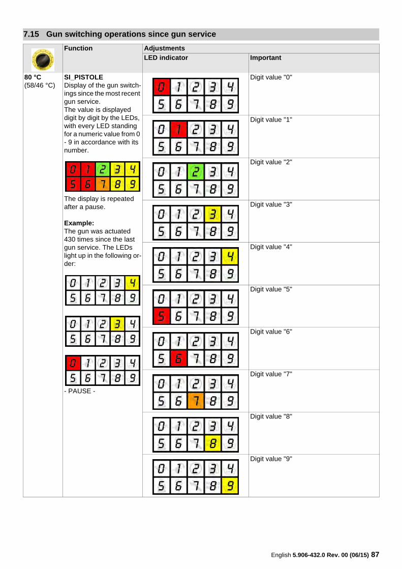
80 °C(58/46 °C)
SI_PISTOLEDisplay of the gun switch-ings since the most recent gun service.The value is displayed digit by digit by the LEDs, with every LED standing for a numeric value from 0 - 9 in accordance with its number.
The display is repeated after a pause.
Example:The gun was actuated 430 times since the last gun service. The LEDs light up in the following or-der:
- PAUSE -
Digit value "0"
Digit value "1"
Digit value "2"
Digit value "3"
Digit value "4"
Digit value "5"
Digit value "6"
Digit value "7"
Digit value "8"
Digit value "9"
88 English 5.906-432.0 Rev. 00 (06/15)
7.16 Gun services
Function Adjustments
LED indicator Important
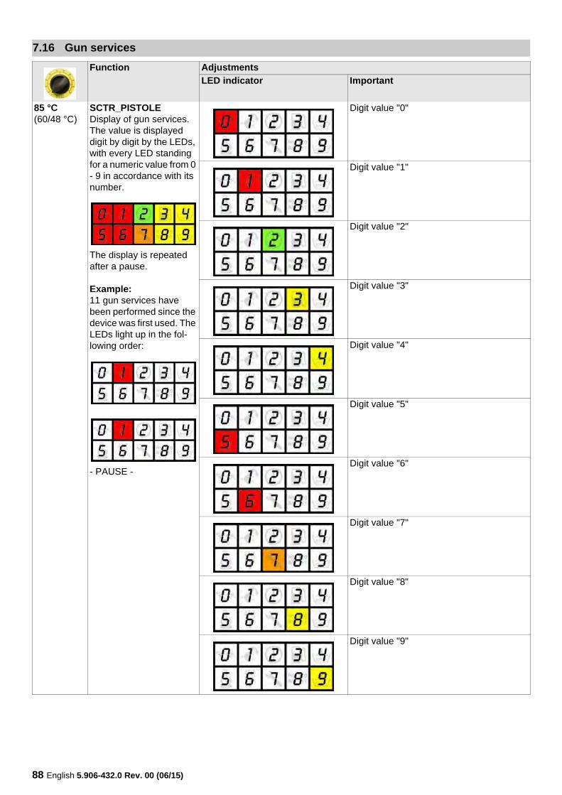
85 °C(60/48 °C)
SCTR_PISTOLEDisplay of gun services.The value is displayed digit by digit by the LEDs, with every LED standing for a numeric value from 0 - 9 in accordance with its number.
The display is repeated after a pause.
Example:11 gun services have been performed since the device was first used. The LEDs light up in the fol-lowing order:
- PAUSE -
Digit value "0"
Digit value "1"
Digit value "2"
Digit value "3"
Digit value "4"
Digit value "5"
Digit value "6"
Digit value "7"
Digit value "8"
Digit value "9"

English 5.906-432.0 Rev. 00 (06/15) 89
85 °C+„SET“(60/48 °C+„SET“)
When switching on the device, the gun switching operations since the gun service (SI_PISTOLE) are reset to "0", the service counter gun (SCTR_PISTOLE) is increased by 1 and the fault memory is deleted.
Function Adjustments
LED indicator Important
90 English 5.906-432.0 Rev. 00 (06/15)
7.17 Gun switches since initial startup
Function Adjustments
LED indicator Important
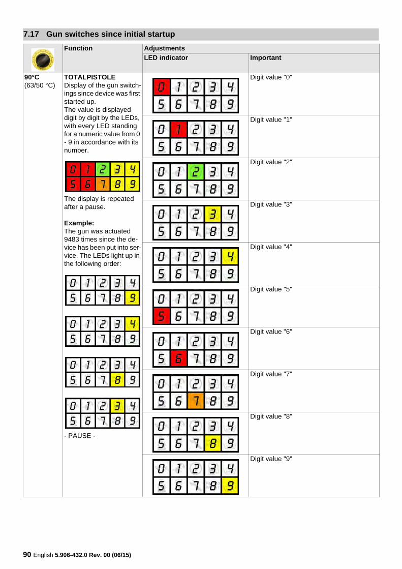
90°C(63/50 °C)
TOTALPISTOLEDisplay of the gun switch-ings since device was first started up.The value is displayed digit by digit by the LEDs, with every LED standing for a numeric value from 0 - 9 in accordance with its number.
The display is repeated after a pause.
Example:The gun was actuated 9483 times since the de-vice has been put into ser-vice. The LEDs light up in the following order:
- PAUSE -
Digit value "0"
Digit value "1"
Digit value "2"
Digit value "3"
Digit value "4"
Digit value "5"
Digit value "6"
Digit value "7"
Digit value "8"
Digit value "9"

English 5.906-432.0 Rev. 00 (06/15) 91
7.18 Operation duration of the burner since burner service
Function Adjustments
LED indicator Important
95°C(66/52 °C)
SI_BrennerDisplay of the operation duration of the burner in hours since the last burn-er service.The value is displayed digit by digit by the LEDs, with every LED standing for a numeric value from 0 - 9 in accordance with its number.
The display is repeated after a pause.
Example:The burner has been in operation for 47 hours since the last burner ser-vice. The LEDs light up in the following order:
- PAUSE -
Digit value "0"
Digit value "1"
Digit value "2"
Digit value "3"
Digit value "4"
Digit value "5"
Digit value "6"
Digit value "7"
Digit value "8"
Digit value "9"
92 English 5.906-432.0 Rev. 00 (06/15)
7.19 Burner service
Function Adjustments
LED indicator Important
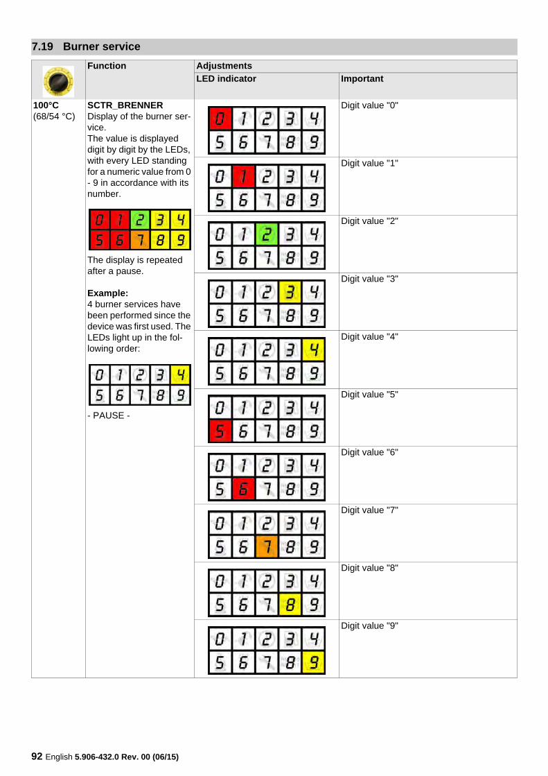
100°C(68/54 °C)
SCTR_BRENNERDisplay of the burner ser-vice.The value is displayed digit by digit by the LEDs, with every LED standing for a numeric value from 0 - 9 in accordance with its number.
The display is repeated after a pause.
Example:4 burner services have been performed since the device was first used. The LEDs light up in the fol-lowing order:
- PAUSE -
Digit value "0"
Digit value "1"
Digit value "2"
Digit value "3"
Digit value "4"
Digit value "5"
Digit value "6"
Digit value "7"
Digit value "8"
Digit value "9"

English 5.906-432.0 Rev. 00 (06/15) 93
100°C+„SET“(68/54 °C+„SET“)
When switching on the device, the burner operation duration since the burner service (SI_BRENNER) is reset to "0", the service counter burner (SCTR_BRENNER) is increased by 1 and the fault memory is de-leted.
Function Adjustments
LED indicator Important
94 English 5.906-432.0 Rev. 00 (06/15)
7.20 Burner operation since initial startup
Function Adjustments
LED indicator Important
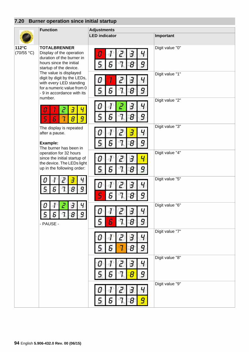
112°C(70/55 °C)
TOTALBRENNERDisplay of the operation duration of the burner in hours since the initial startup of the device.The value is displayed digit by digit by the LEDs, with every LED standing for a numeric value from 0 - 9 in accordance with its number.
The display is repeated after a pause.
Example:The burner has been in operation for 32 hours since the initial startup of the device. The LEDs light up in the following order:
- PAUSE -
Digit value "0"
Digit value "1"
Digit value "2"
Digit value "3"
Digit value "4"
Digit value "5"
Digit value "6"
Digit value "7"
Digit value "8"
Digit value "9"
English 5.906-432.0 Rev. 00 (06/15) 95
7.21 Operating hours of the pump since pump service
Function Adjustments
LED indicator Important
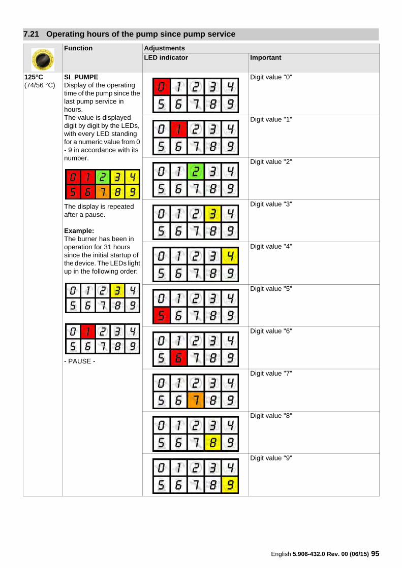
125°C(74/56 °C)
SI_PUMPEDisplay of the operating time of the pump since the last pump service in hours.The value is displayed digit by digit by the LEDs, with every LED standing for a numeric value from 0 - 9 in accordance with its number.
The display is repeated after a pause.
Example:The burner has been in operation for 31 hours since the initial startup of the device. The LEDs light up in the following order:
- PAUSE -
Digit value "0"
Digit value "1"
Digit value "2"
Digit value "3"
Digit value "4"
Digit value "5"
Digit value "6"
Digit value "7"
Digit value "8"
Digit value "9"
96 English 5.906-432.0 Rev. 00 (06/15)
7.22 Pump service
Function Adjustments
LED indicator Important
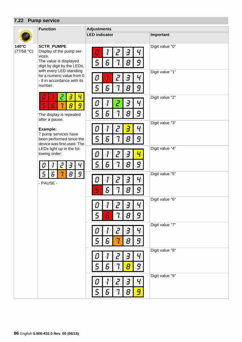
140°C(77/58 °C)
SCTR_PUMPEDisplay of the pump ser-vices.The value is displayed digit by digit by the LEDs, with every LED standing for a numeric value from 0 - 9 in accordance with its number.
The display is repeated after a pause.
Example:7 pump services have been performed since the device was first used. The LEDs light up in the fol-lowing order:
- PAUSE -
Digit value "0"
Digit value "1"
Digit value "2"
Digit value "3"
Digit value "4"
Digit value "5"
Digit value "6"
Digit value "7"
Digit value "8"
Digit value "9"
English 5.906-432.0 Rev. 00 (06/15) 97
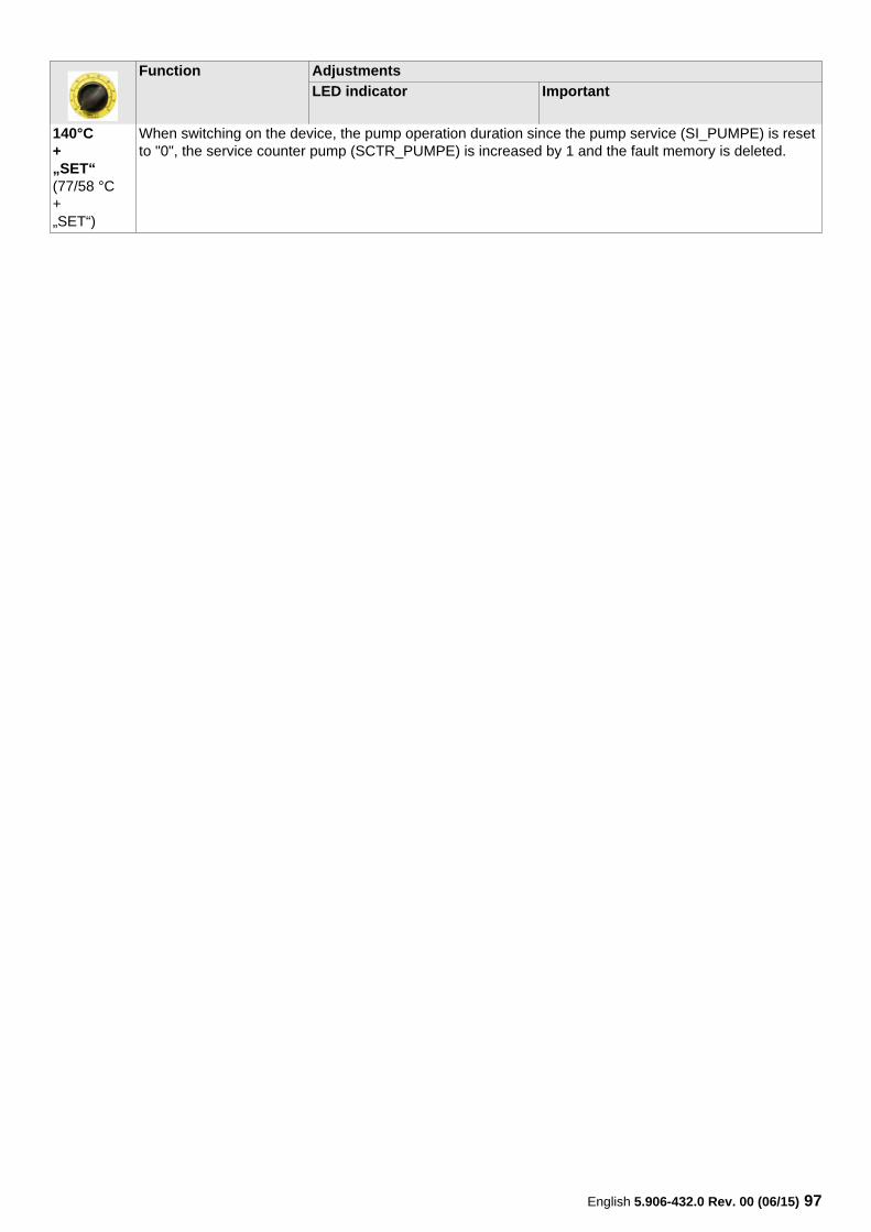
140°C+„SET“(77/58 °C+„SET“)
When switching on the device, the pump operation duration since the pump service (SI_PUMPE) is reset to "0", the service counter pump (SCTR_PUMPE) is increased by 1 and the fault memory is deleted.
Function Adjustments
LED indicator Important
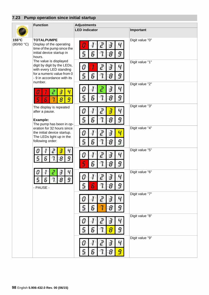
98 English 5.906-432.0 Rev. 00 (06/15)
7.23 Pump operation since initial startup
Function Adjustments
LED indicator Important
155°C(80/60 °C)
TOTALPUMPEDisplay of the operating time of the pump since the initial device startup in hours.The value is displayed digit by digit by the LEDs, with every LED standing for a numeric value from 0 - 9 in accordance with its number.
The display is repeated after a pause.
Example:The pump has been in op-eration for 32 hours since the initial device startup. The LEDs light up in the following order:
- PAUSE -
Digit value "0"
Digit value "1"
Digit value "2"
Digit value "3"
Digit value "4"
Digit value "5"
Digit value "6"
Digit value "7"
Digit value "8"
Digit value "9"
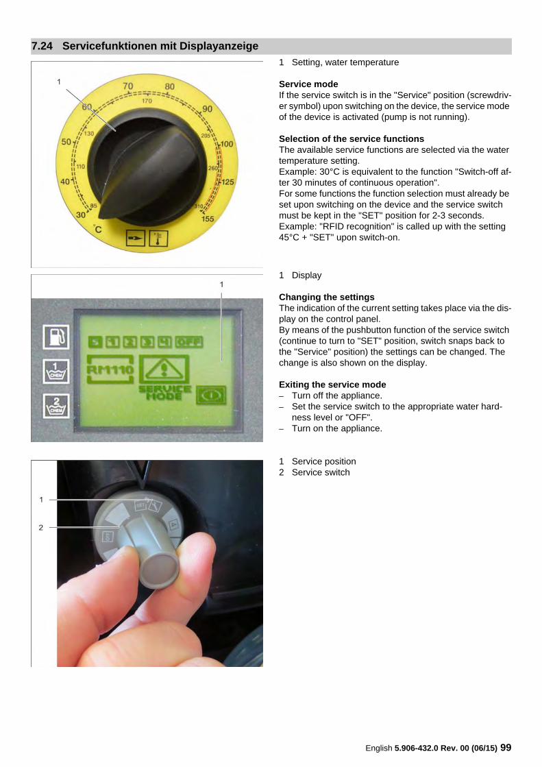
English 5.906-432.0 Rev. 00 (06/15) 99
1 Setting, water temperature
Service modeIf the service switch is in the "Service" position (screwdriv-er symbol) upon switching on the device, the service mode of the device is activated (pump is not running).
Selection of the service functionsThe available service functions are selected via the water temperature setting.Example: 30°C is equivalent to the function "Switch-off af-ter 30 minutes of continuous operation".For some functions the function selection must already be set upon switching on the device and the service switch must be kept in the "SET" position for 2-3 seconds.Example: "RFID recognition" is called up with the setting 45°C + "SET" upon switch-on.
1 Display
Changing the settingsThe indication of the current setting takes place via the dis-play on the control panel.By means of the pushbutton function of the service switch (continue to turn to "SET" position, switch snaps back to the "Service" position) the settings can be changed. The change is also shown on the display.
Exiting the service mode– Turn off the appliance. – Set the service switch to the appropriate water hard-
ness level or "OFF".– Turn on the appliance.
1 Service position2 Service switch
7.24 Servicefunktionen mit Displayanzeige
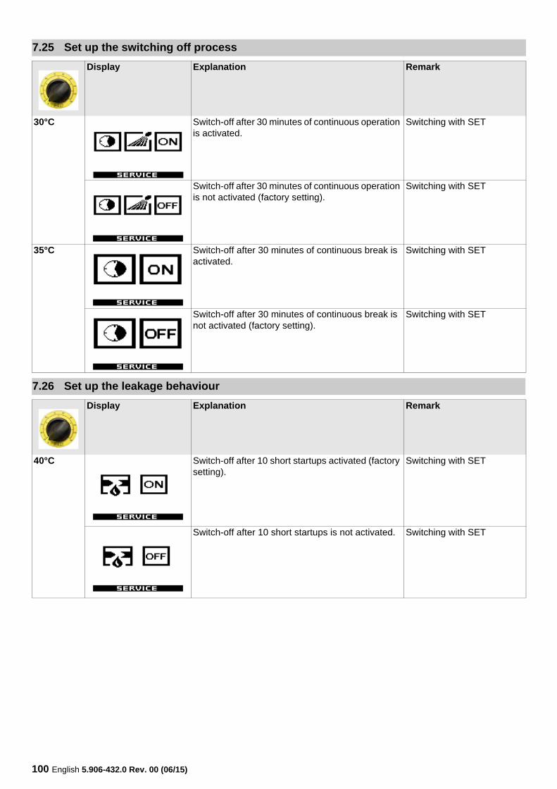
100 English 5.906-432.0 Rev. 00 (06/15)
7.25 Set up the switching off process
Display Explanation Remark
30°C Switch-off after 30 minutes of continuous operation is activated.
Switching with SET
Switch-off after 30 minutes of continuous operation is not activated (factory setting).
Switching with SET
35°C Switch-off after 30 minutes of continuous break is activated.
Switching with SET
Switch-off after 30 minutes of continuous break is not activated (factory setting).
Switching with SET
7.26 Set up the leakage behaviour
Display Explanation Remark
40°C Switch-off after 10 short startups activated (factory setting).
Switching with SET
Switch-off after 10 short startups is not activated. Switching with SET
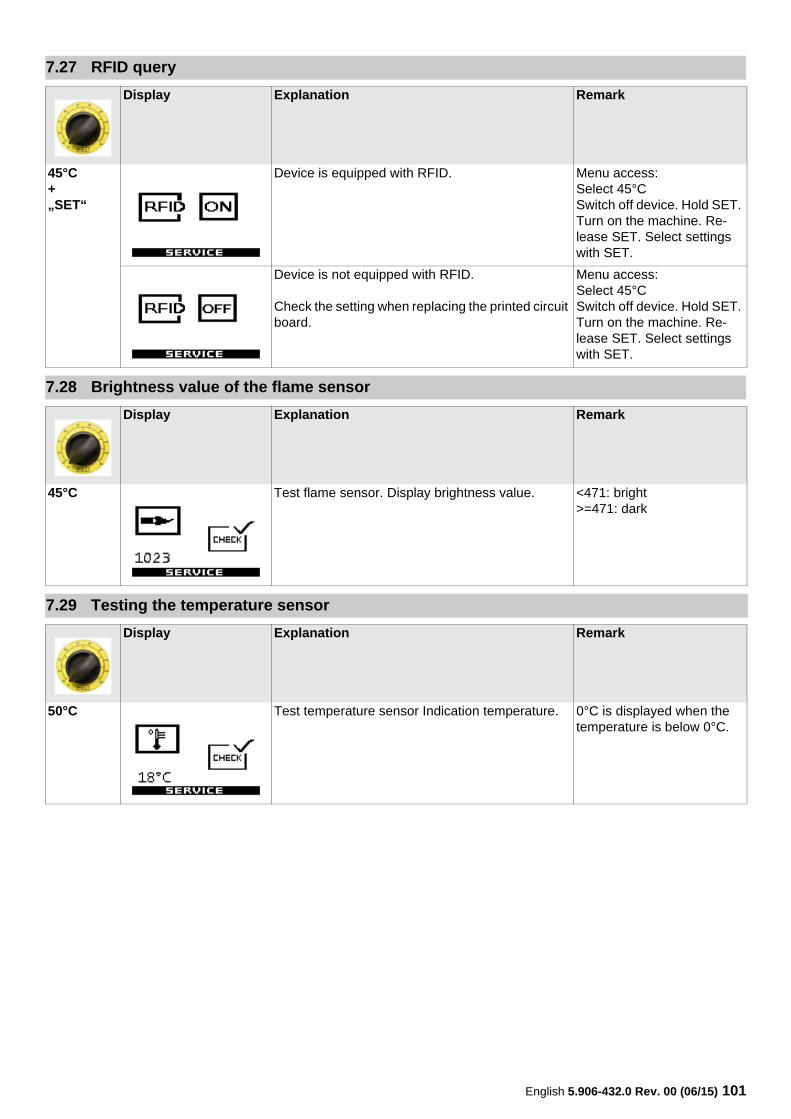
English 5.906-432.0 Rev. 00 (06/15) 101
7.27 RFID query
Display Explanation Remark
45°C+„SET“
Device is equipped with RFID. Menu access:Select 45°CSwitch off device. Hold SET. Turn on the machine. Re-lease SET. Select settings with SET.
Device is not equipped with RFID.
Check the setting when replacing the printed circuit board.
Menu access:Select 45°CSwitch off device. Hold SET. Turn on the machine. Re-lease SET. Select settings with SET.
7.28 Brightness value of the flame sensor
Display Explanation Remark
45°C Test flame sensor. Display brightness value. <471: bright>=471: dark
7.29 Testing the temperature sensor
Display Explanation Remark
50°C Test temperature sensor Indication temperature. 0°C is displayed when the temperature is below 0°C.
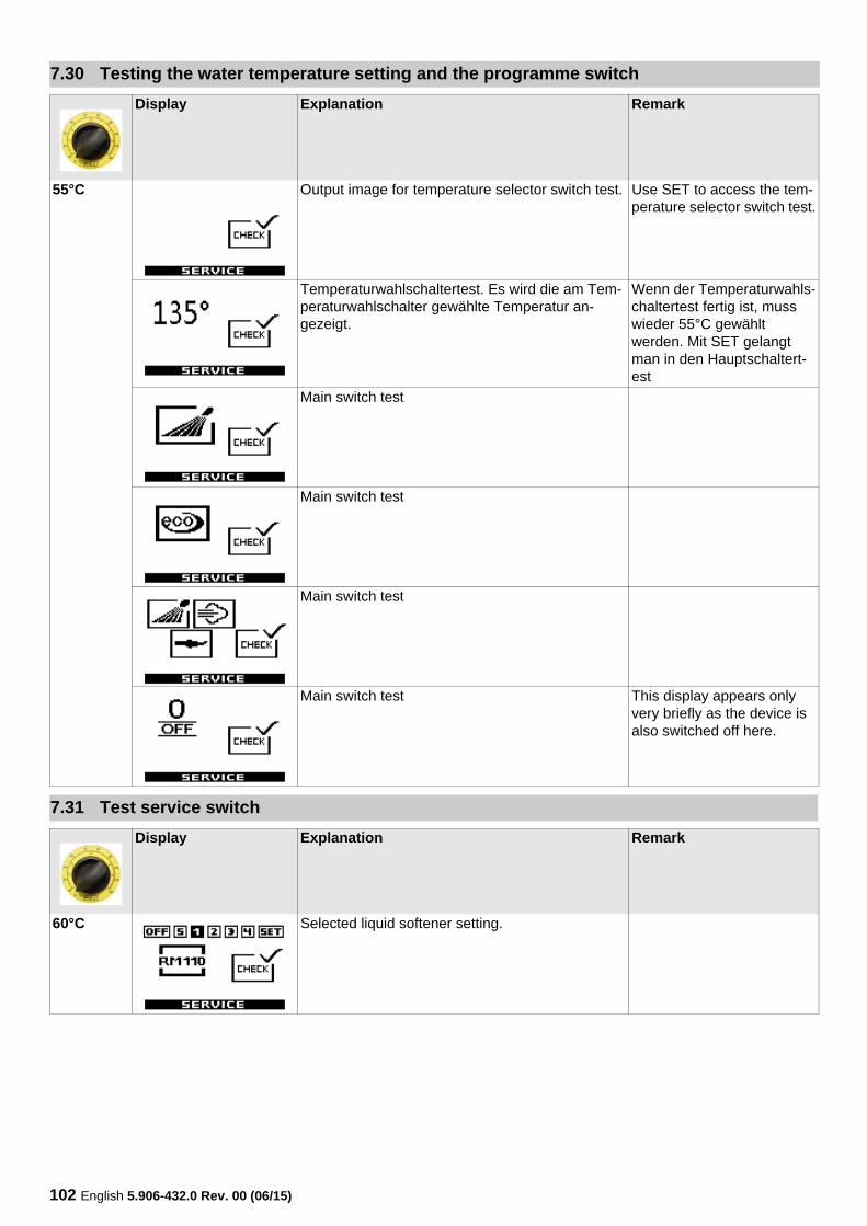
102 English 5.906-432.0 Rev. 00 (06/15)
7.30 Testing the water temperature setting and the programme switch
Display Explanation Remark
55°C Output image for temperature selector switch test. Use SET to access the tem-perature selector switch test.
Temperaturwahlschaltertest. Es wird die am Tem-peraturwahlschalter gewählte Temperatur an-gezeigt.
Wenn der Temperaturwahls-chaltertest fertig ist, muss wieder 55°C gewählt werden. Mit SET gelangt man in den Hauptschaltert-est
Main switch test
Main switch test
Main switch test
Main switch test This display appears only very briefly as the device is also switched off here.
7.31 Test service switch
Display Explanation Remark
60°C Selected liquid softener setting.
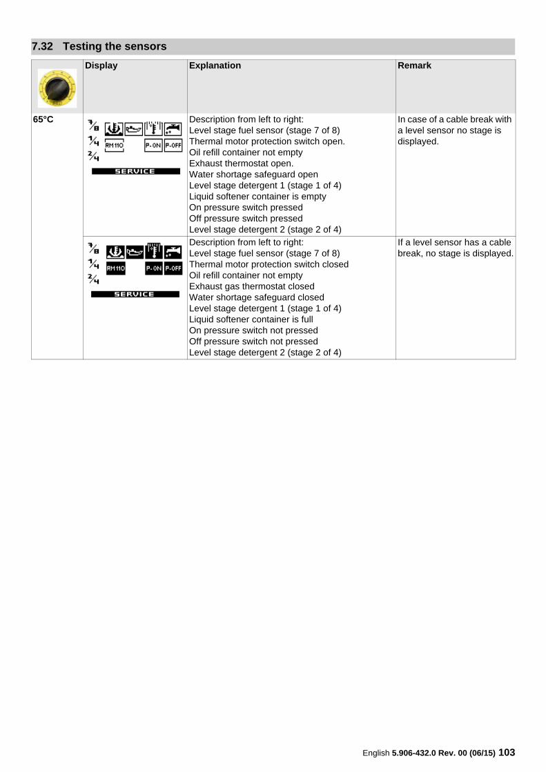
English 5.906-432.0 Rev. 00 (06/15) 103
7.32 Testing the sensors
Display Explanation Remark
65°C Description from left to right:Level stage fuel sensor (stage 7 of 8)Thermal motor protection switch open.Oil refill container not emptyExhaust thermostat open.Water shortage safeguard openLevel stage detergent 1 (stage 1 of 4)Liquid softener container is emptyOn pressure switch pressedOff pressure switch pressedLevel stage detergent 2 (stage 2 of 4)
In case of a cable break with a level sensor no stage is displayed.
Description from left to right:Level stage fuel sensor (stage 7 of 8)Thermal motor protection switch closedOil refill container not emptyExhaust gas thermostat closedWater shortage safeguard closed Level stage detergent 1 (stage 1 of 4)Liquid softener container is fullOn pressure switch not pressedOff pressure switch not pressedLevel stage detergent 2 (stage 2 of 4)
If a level sensor has a cable break, no stage is displayed.
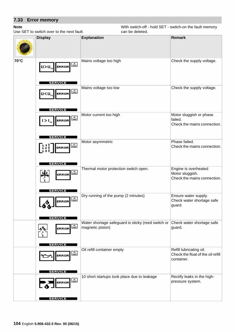
104 English 5.906-432.0 Rev. 00 (06/15)
NoteUse SET to switch over to the next fault.
With switch-off - hold SET - switch-on the fault memory can be deleted.
7.33 Error memory
Display Explanation Remark
70°C Mains voltage too high Check the supply voltage.
Mains voltage too low Check the supply voltage.
Motor current too high Motor sluggish or phase failed.Check the mains connection.
Motor asymmetric Phase failed.Check the mains connection.
Thermal motor protection switch open. Engine is overheatedMotor sluggish.Check the mains connection.
Dry running of the pump (2 minutes) Ensure water supply.Check water shortage safe guard.
Water shortage safeguard is sticky (reed switch or magnetic piston)
Check water shortage safe guard.
Oil refill container empty Refill lubricating oil.Check the float of the oil refill container.
10 short startups took place due to leakage Rectify leaks in the high-pressure system.
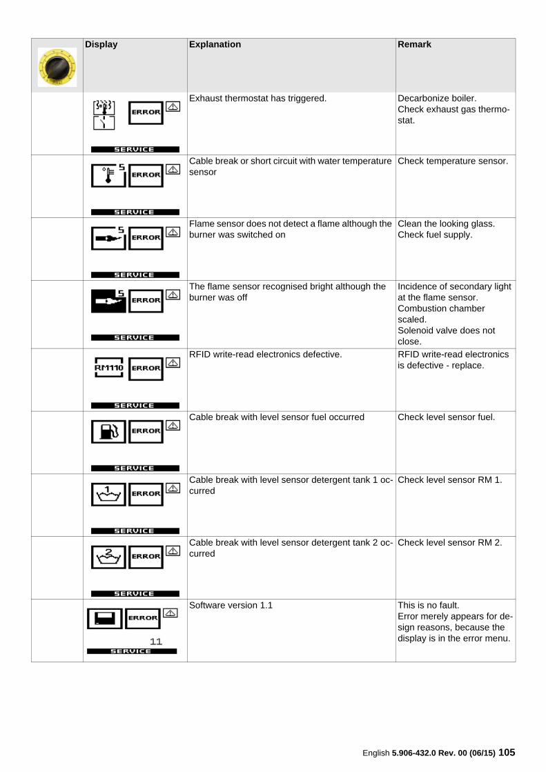
English 5.906-432.0 Rev. 00 (06/15) 105
Exhaust thermostat has triggered. Decarbonize boiler.Check exhaust gas thermo-stat.
Cable break or short circuit with water temperature sensor
Check temperature sensor.
Flame sensor does not detect a flame although the burner was switched on
Clean the looking glass.Check fuel supply.
The flame sensor recognised bright although the burner was off
Incidence of secondary light at the flame sensor.Combustion chamber scaled.Solenoid valve does not close.
RFID write-read electronics defective. RFID write-read electronics is defective - replace.
Cable break with level sensor fuel occurred Check level sensor fuel.
Cable break with level sensor detergent tank 1 oc-curred
Check level sensor RM 1.
Cable break with level sensor detergent tank 2 oc-curred
Check level sensor RM 2.
Software version 1.1 This is no fault.Error merely appears for de-sign reasons, because the display is in the error menu.
Display Explanation Remark
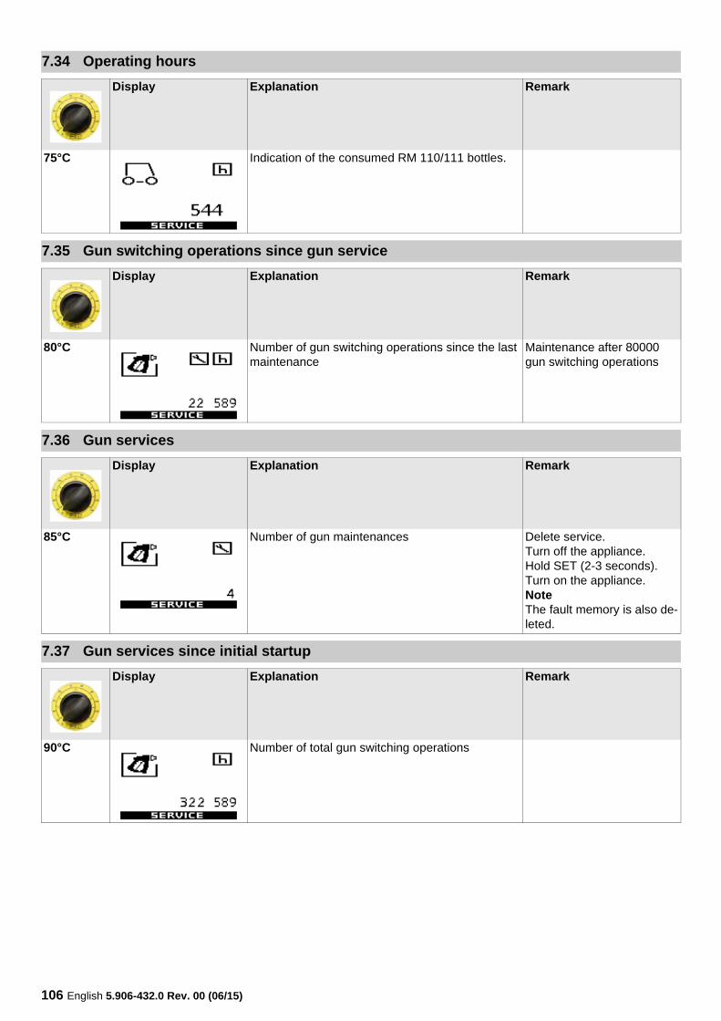
106 English 5.906-432.0 Rev. 00 (06/15)
7.34 Operating hours
Display Explanation Remark
75°C Indication of the consumed RM 110/111 bottles.
7.35 Gun switching operations since gun service
Display Explanation Remark
80°C Number of gun switching operations since the last maintenance
Maintenance after 80000 gun switching operations
7.36 Gun services
Display Explanation Remark
85°C Number of gun maintenances Delete service.Turn off the appliance. Hold SET (2-3 seconds).Turn on the appliance.NoteThe fault memory is also de-leted.
7.37 Gun services since initial startup
Display Explanation Remark
90°C Number of total gun switching operations
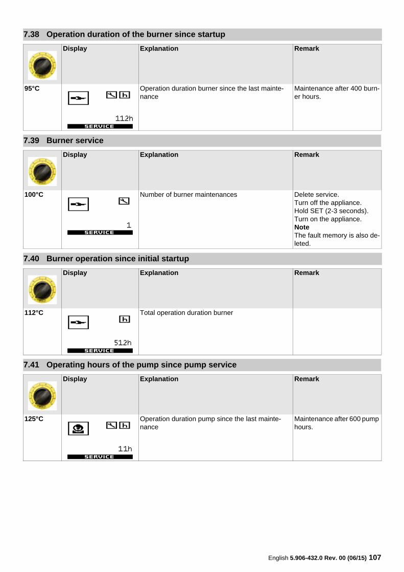
English 5.906-432.0 Rev. 00 (06/15) 107
7.38 Operation duration of the burner since startup
Display Explanation Remark
95°C Operation duration burner since the last mainte-nance
Maintenance after 400 burn-er hours.
7.39 Burner service
Display Explanation Remark
100°C Number of burner maintenances Delete service.Turn off the appliance. Hold SET (2-3 seconds).Turn on the appliance.NoteThe fault memory is also de-leted.
7.40 Burner operation since initial startup
Display Explanation Remark
112°C Total operation duration burner
7.41 Operating hours of the pump since pump service
Display Explanation Remark
125°C Operation duration pump since the last mainte-nance
Maintenance after 600 pump hours.
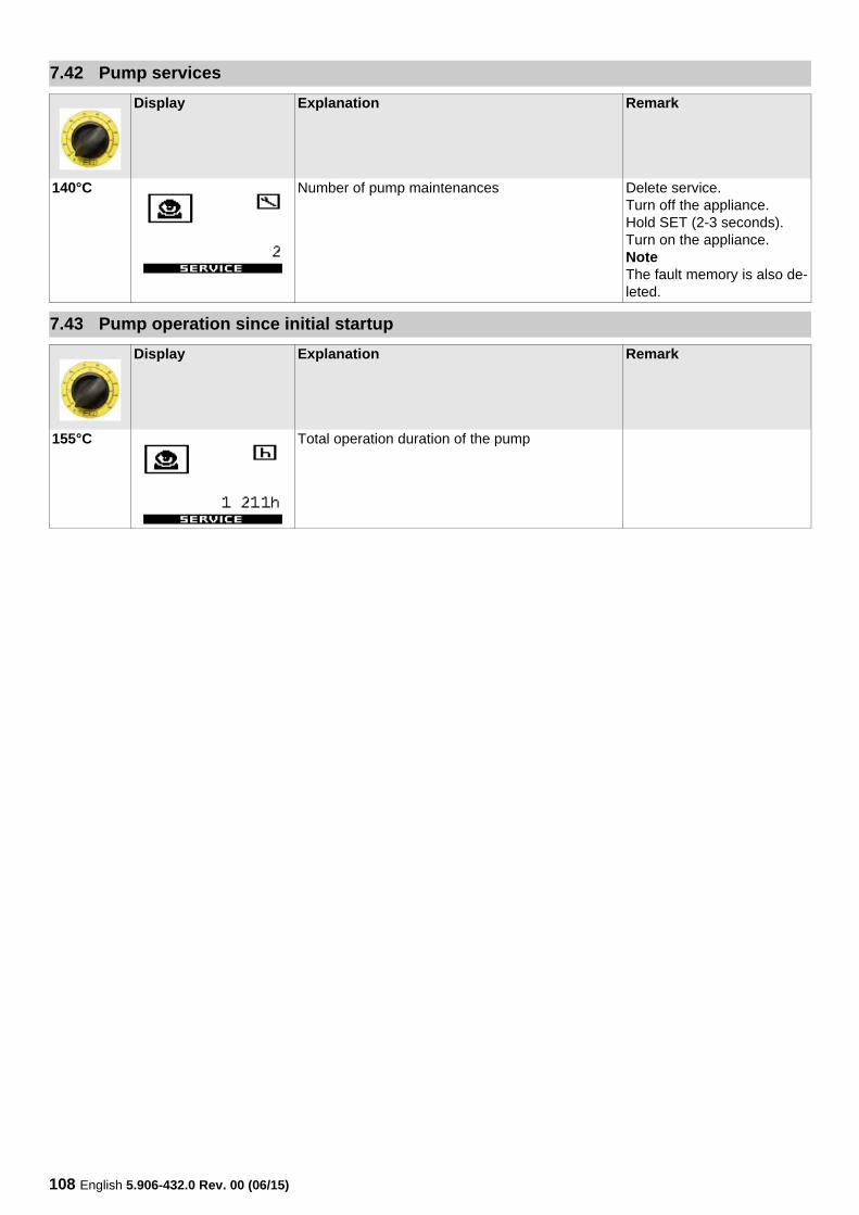
108 English 5.906-432.0 Rev. 00 (06/15)
7.42 Pump services
Display Explanation Remark
140°C Number of pump maintenances Delete service.Turn off the appliance. Hold SET (2-3 seconds).Turn on the appliance.NoteThe fault memory is also de-leted.
7.43 Pump operation since initial startup
Display Explanation Remark
155°C Total operation duration of the pump
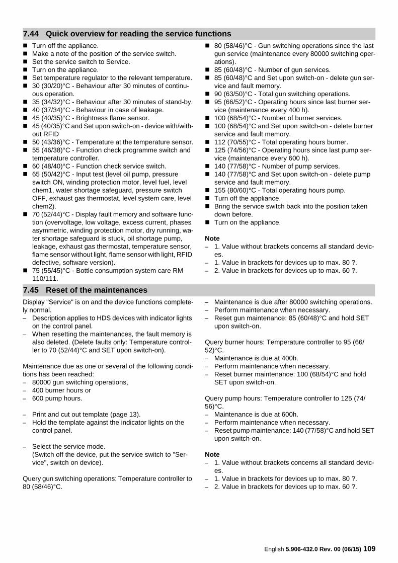
English 5.906-432.0 Rev. 00 (06/15) 109
Turn off the appliance. Make a note of the position of the service switch. Set the service switch to Service. Turn on the appliance. Set temperature regulator to the relevant temperature. 30 (30/20)°C - Behaviour after 30 minutes of continu-
ous operation. 35 (34/32)°C - Behaviour after 30 minutes of stand-by. 40 (37/34)°C - Behaviour in case of leakage. 45 (40/35)°C - Brightness flame sensor. 45 (40/35)°C and Set upon switch-on - device with/with-
out RFID 50 (43/36)°C - Temperature at the temperature sensor. 55 (46/38)°C - Function check programme switch and
temperature controller. 60 (48/40)°C - Function check service switch. 65 (50/42)°C - Input test (level oil pump, pressure
switch ON, winding protection motor, level fuel, level chem1, water shortage safeguard, pressure switch OFF, exhaust gas thermostat, level system care, level chem2).
70 (52/44)°C - Display fault memory and software func-tion (overvoltage, low voltage, excess current, phases asymmetric, winding protection motor, dry running, wa-ter shortage safeguard is stuck, oil shortage pump, leakage, exhaust gas thermostat, temperature sensor, flame sensor without light, flame sensor with light, RFID defective, software version).
75 (55/45)°C - Bottle consumption system care RM 110/111.
80 (58/46)°C - Gun switching operations since the last gun service (maintenance every 80000 switching oper-ations).
85 (60/48)°C - Number of gun services. 85 (60/48)°C and Set upon switch-on - delete gun ser-
vice and fault memory. 90 (63/50)°C - Total gun switching operations. 95 (66/52)°C - Operating hours since last burner ser-
vice (maintenance every 400 h). 100 (68/54)°C - Number of burner services. 100 (68/54)°C and Set upon switch-on - delete burner
service and fault memory. 112 (70/55)°C - Total operating hours burner. 125 (74/56)°C - Operating hours since last pump ser-
vice (maintenance every 600 h). 140 (77/58)°C - Number of pump services. 140 (77/58)°C and Set upon switch-on - delete pump
service and fault memory. 155 (80/60)°C - Total operating hours pump. Turn off the appliance. Bring the service switch back into the position taken
down before. Turn on the appliance.
Note– 1. Value without brackets concerns all standard devic-
es.– 1. Value in brackets for devices up to max. 80 ?.– 2. Value in brackets for devices up to max. 60 ?.
Display "Service" is on and the device functions complete-ly normal.– Description applies to HDS devices with indicator lights
on the control panel.– When resetting the maintenances, the fault memory is
also deleted. (Delete faults only: Temperature control-ler to 70 (52/44)°C and SET upon switch-on).
Maintenance due as one or several of the following condi-tions has been reached:– 80000 gun switching operations,– 400 burner hours or– 600 pump hours.
– Print and cut out template (page 13).– Hold the template against the indicator lights on the
control panel.
– Select the service mode.(Switch off the device, put the service switch to "Ser-vice", switch on device).
Query gun switching operations: Temperature controller to 80 (58/46)°C.
– Maintenance is due after 80000 switching operations.– Perform maintenance when necessary.– Reset gun maintenance: 85 (60/48)°C and hold SET
upon switch-on.
Query burner hours: Temperature controller to 95 (66/52)°C.– Maintenance is due at 400h.– Perform maintenance when necessary.– Reset burner maintenance: 100 (68/54)°C and hold
SET upon switch-on.
Query pump hours: Temperature controller to 125 (74/56)°C.– Maintenance is due at 600h.– Perform maintenance when necessary.– Reset pump maintenance: 140 (77/58)°C and hold SET
upon switch-on.
Note– 1. Value without brackets concerns all standard devic-
es.– 1. Value in brackets for devices up to max. 80 ?.– 2. Value in brackets for devices up to max. 60 ?.
7.44 Quick overview for reading the service functions
7.45 Reset of the maintenances
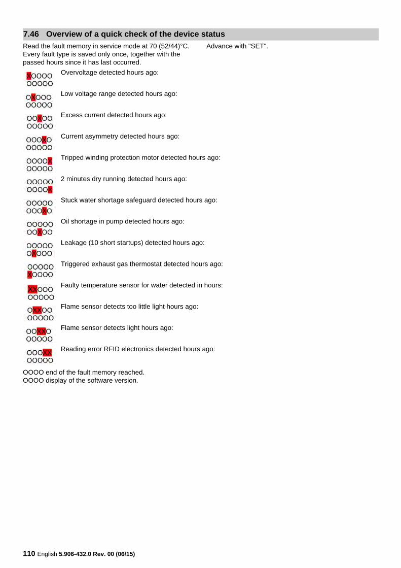
110 English 5.906-432.0 Rev. 00 (06/15)
Read the fault memory in service mode at 70 (52/44)°C. Every fault type is saved only once, together with the passed hours since it has last occurred.
Advance with "SET".
OOOO end of the fault memory reached.OOOO display of the software version.
7.46 Overview of a quick check of the device status
Overvoltage detected hours ago:
Low voltage range detected hours ago:
Excess current detected hours ago:
Current asymmetry detected hours ago:
Tripped winding protection motor detected hours ago:
2 minutes dry running detected hours ago:
Stuck water shortage safeguard detected hours ago:
Oil shortage in pump detected hours ago:
Leakage (10 short startups) detected hours ago:
Triggered exhaust gas thermostat detected hours ago:
Faulty temperature sensor for water detected in hours:
Flame sensor detects too little light hours ago:
Flame sensor detects light hours ago:
Reading error RFID electronics detected hours ago:
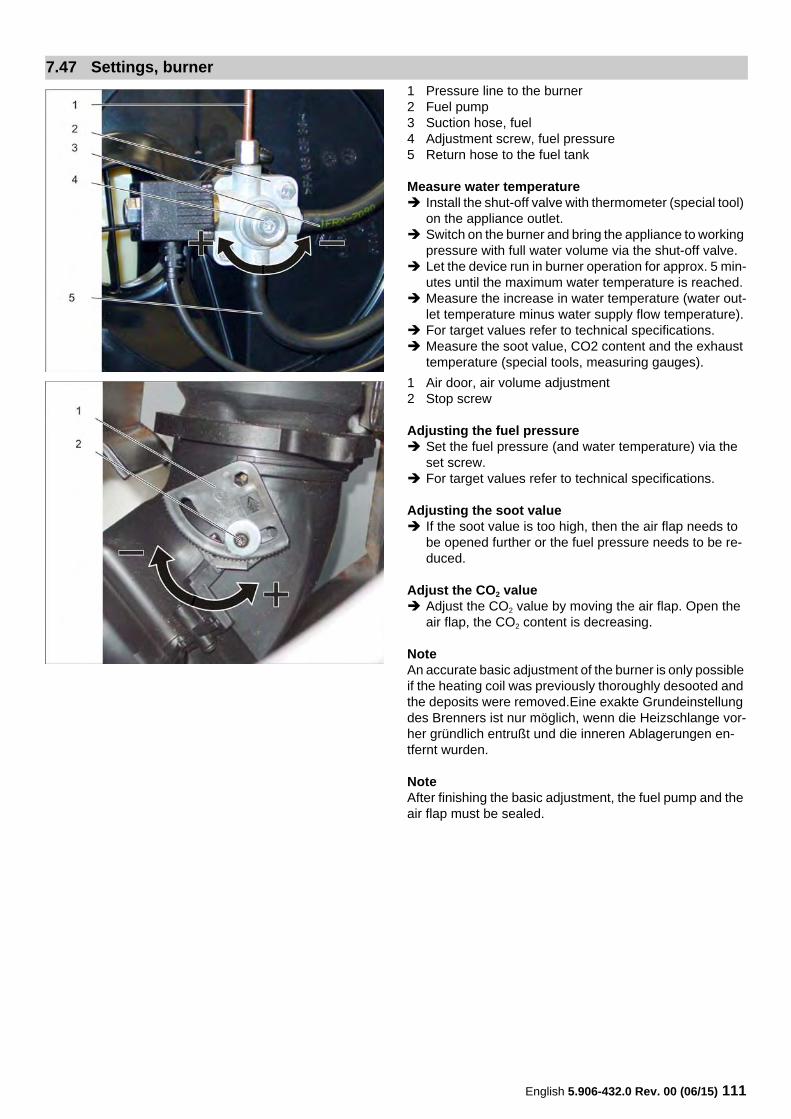
English 5.906-432.0 Rev. 00 (06/15) 111
1 Pressure line to the burner2 Fuel pump3 Suction hose, fuel4 Adjustment screw, fuel pressure5 Return hose to the fuel tank
Measure water temperature Install the shut-off valve with thermometer (special tool)
on the appliance outlet. Switch on the burner and bring the appliance to working
pressure with full water volume via the shut-off valve. Let the device run in burner operation for approx. 5 min-
utes until the maximum water temperature is reached. Measure the increase in water temperature (water out-
let temperature minus water supply flow temperature). For target values refer to technical specifications. Measure the soot value, CO2 content and the exhaust
temperature (special tools, measuring gauges).
1 Air door, air volume adjustment2 Stop screw
Adjusting the fuel pressure Set the fuel pressure (and water temperature) via the
set screw. For target values refer to technical specifications.
Adjusting the soot value If the soot value is too high, then the air flap needs to
be opened further or the fuel pressure needs to be re-duced.
Adjust the CO2 value Adjust the CO2 value by moving the air flap. Open the
air flap, the CO2 content is decreasing.
NoteAn accurate basic adjustment of the burner is only possible if the heating coil was previously thoroughly desooted and the deposits were removed.Eine exakte Grundeinstellung des Brenners ist nur möglich, wenn die Heizschlange vor-her gründlich entrußt und die inneren Ablagerungen en-tfernt wurden.
NoteAfter finishing the basic adjustment, the fuel pump and the air flap must be sealed.
7.47 Settings, burner
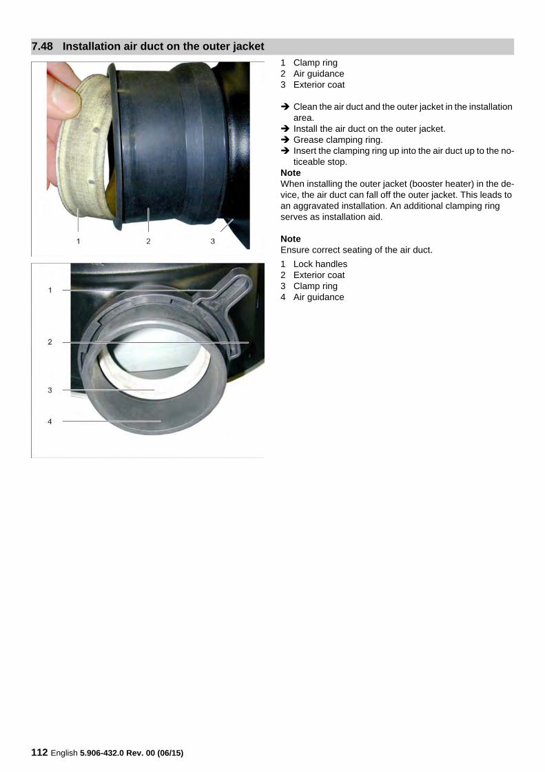
112 English 5.906-432.0 Rev. 00 (06/15)
1 Clamp ring2 Air guidance3 Exterior coat
Clean the air duct and the outer jacket in the installation area.
Install the air duct on the outer jacket. Grease clamping ring. Insert the clamping ring up into the air duct up to the no-
ticeable stop.NoteWhen installing the outer jacket (booster heater) in the de-vice, the air duct can fall off the outer jacket. This leads to an aggravated installation. An additional clamping ring serves as installation aid.
NoteEnsure correct seating of the air duct.
1 Lock handles2 Exterior coat3 Clamp ring4 Air guidance
7.48 Installation air duct on the outer jacket
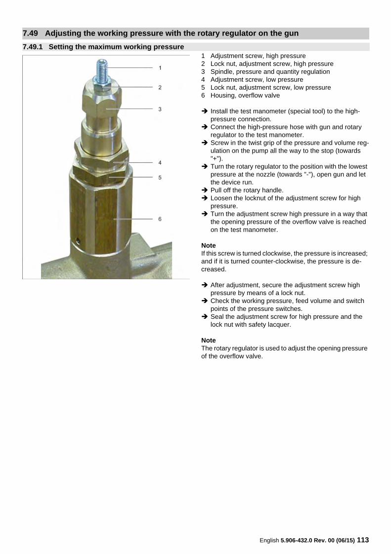
English 5.906-432.0 Rev. 00 (06/15) 113
1 Adjustment screw, high pressure2 Lock nut, adjustment screw, high pressure3 Spindle, pressure and quantity regulation4 Adjustment screw, low pressure5 Lock nut, adjustment screw, low pressure6 Housing, overflow valve
Install the test manometer (special tool) to the high-pressure connection.
Connect the high-pressure hose with gun and rotary regulator to the test manometer.
Screw in the twist grip of the pressure and volume reg-ulation on the pump all the way to the stop (towards "+").
Turn the rotary regulator to the position with the lowest pressure at the nozzle (towards "-"), open gun and let the device run.
Pull off the rotary handle. Loosen the locknut of the adjustment screw for high
pressure. Turn the adjustment screw high pressure in a way that
the opening pressure of the overflow valve is reached on the test manometer.
NoteIf this screw is turned clockwise, the pressure is increased; and if it is turned counter-clockwise, the pressure is de-creased.
After adjustment, secure the adjustment screw high pressure by means of a lock nut.
Check the working pressure, feed volume and switch points of the pressure switches.
Seal the adjustment screw for high pressure and the lock nut with safety lacquer.
NoteThe rotary regulator is used to adjust the opening pressure of the overflow valve.
7.49 Adjusting the working pressure with the rotary regulator on the gun
7.49.1 Setting the maximum working pressure
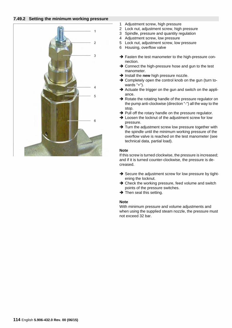
114 English 5.906-432.0 Rev. 00 (06/15)
1 Adjustment screw, high pressure2 Lock nut, adjustment screw, high pressure3 Spindle, pressure and quantity regulation4 Adjustment screw, low pressure5 Lock nut, adjustment screw, low pressure6 Housing, overflow valve
Fasten the test manometer to the high-pressure con-nection.
Connect the high-pressure hose and gun to the test manometer.
Install the new high pressure nozzle. Completely open the control knob on the gun (turn to-
wards "+"). Actuate the trigger on the gun and switch on the appli-
ance. Rotate the rotating handle of the pressure regulator on
the pump anti-clockwise (direction "-") all the way to the stop.
Pull off the rotary handle on the pressure regulator. Loosen the locknut of the adjustment screw for low
pressure. Turn the adjustment screw low pressure together with
the spindle until the minimum working pressure of the overflow valve is reached on the test manometer (see technical data, partial load).
NoteIf this screw is turned clockwise, the pressure is increased; and if it is turned counter-clockwise, the pressure is de-creased.
Secure the adjustment screw for low pressure by tight-ening the locknut.
Check the working pressure, feed volume and switch points of the pressure switches.
Then seal this setting.
NoteWith minimum pressure and volume adjustments and when using the supplied steam nozzle, the pressure must not exceed 32 bar.
7.49.2 Setting the minimum working pressure
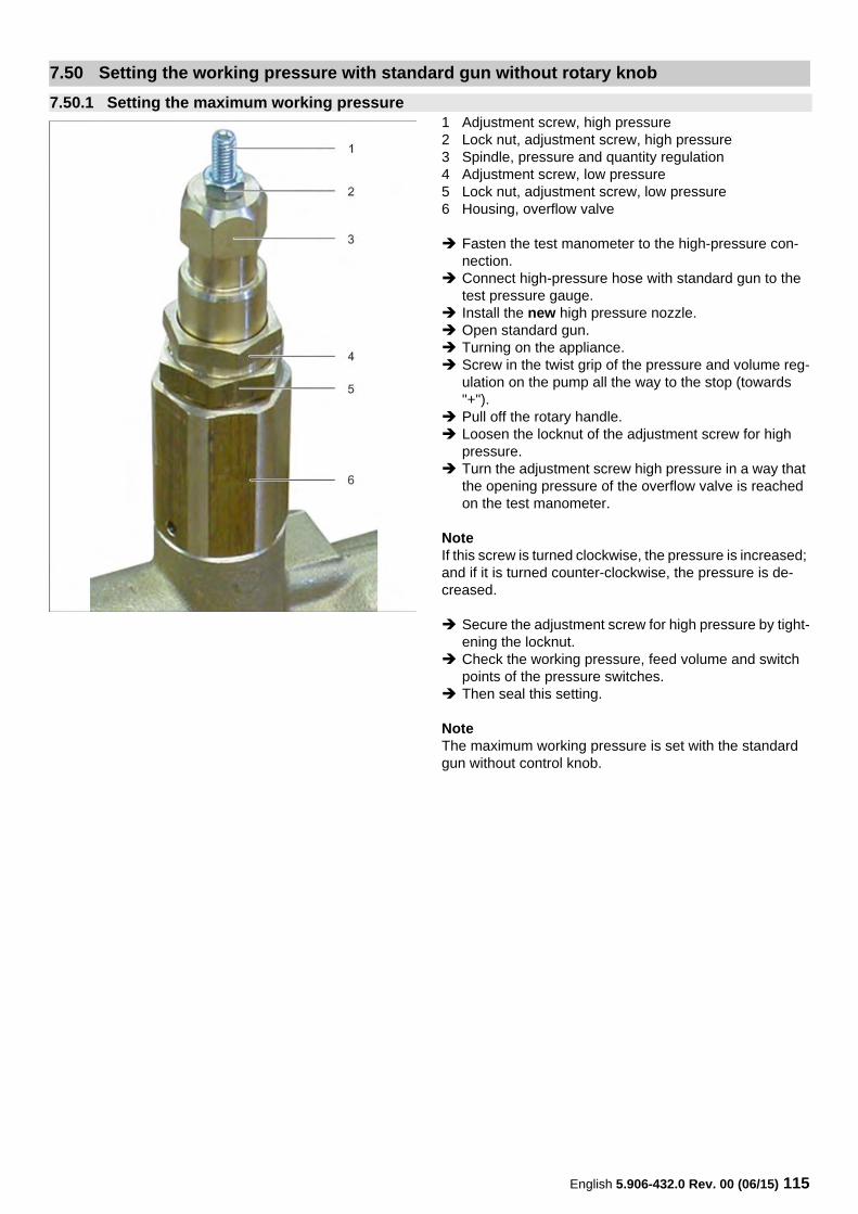
English 5.906-432.0 Rev. 00 (06/15) 115
1 Adjustment screw, high pressure2 Lock nut, adjustment screw, high pressure3 Spindle, pressure and quantity regulation4 Adjustment screw, low pressure5 Lock nut, adjustment screw, low pressure6 Housing, overflow valve
Fasten the test manometer to the high-pressure con-nection.
Connect high-pressure hose with standard gun to the test pressure gauge.
Install the new high pressure nozzle. Open standard gun. Turning on the appliance. Screw in the twist grip of the pressure and volume reg-
ulation on the pump all the way to the stop (towards "+").
Pull off the rotary handle. Loosen the locknut of the adjustment screw for high
pressure. Turn the adjustment screw high pressure in a way that
the opening pressure of the overflow valve is reached on the test manometer.
NoteIf this screw is turned clockwise, the pressure is increased; and if it is turned counter-clockwise, the pressure is de-creased.
Secure the adjustment screw for high pressure by tight-ening the locknut.
Check the working pressure, feed volume and switch points of the pressure switches.
Then seal this setting.
NoteThe maximum working pressure is set with the standard gun without control knob.
7.50 Setting the working pressure with standard gun without rotary knob
7.50.1 Setting the maximum working pressure
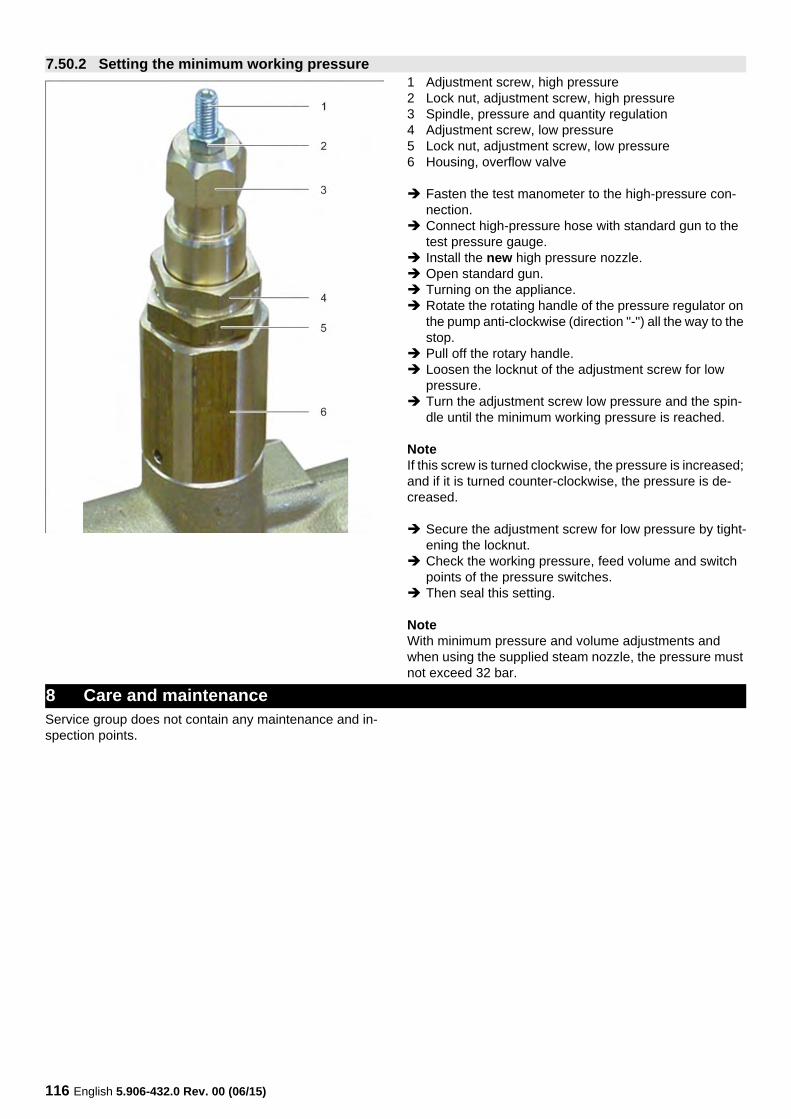
116 English 5.906-432.0 Rev. 00 (06/15)
1 Adjustment screw, high pressure2 Lock nut, adjustment screw, high pressure3 Spindle, pressure and quantity regulation4 Adjustment screw, low pressure5 Lock nut, adjustment screw, low pressure6 Housing, overflow valve
Fasten the test manometer to the high-pressure con-nection.
Connect high-pressure hose with standard gun to the test pressure gauge.
Install the new high pressure nozzle. Open standard gun. Turning on the appliance. Rotate the rotating handle of the pressure regulator on
the pump anti-clockwise (direction "-") all the way to the stop.
Pull off the rotary handle. Loosen the locknut of the adjustment screw for low
pressure. Turn the adjustment screw low pressure and the spin-
dle until the minimum working pressure is reached.
NoteIf this screw is turned clockwise, the pressure is increased; and if it is turned counter-clockwise, the pressure is de-creased.
Secure the adjustment screw for low pressure by tight-ening the locknut.
Check the working pressure, feed volume and switch points of the pressure switches.
Then seal this setting.
NoteWith minimum pressure and volume adjustments and when using the supplied steam nozzle, the pressure must not exceed 32 bar.
Service group does not contain any maintenance and in-spection points.
7.50.2 Setting the minimum working pressure
8 Care and maintenance
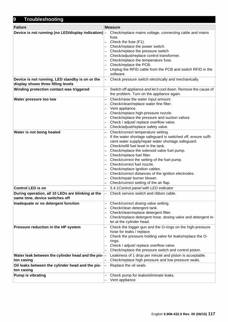
English 5.906-432.0 Rev. 00 (06/15) 117
9 Troubleshooting
Failure Measure
Device is not running (no LED/display indication) – Check/replace mains voltage, connecting cable and mains fuse.
– Check the fuse (F1).– Check/replace the power switch.– Check/replace the pressure switch– Check/adjust/replace control transformer.– Check/replace the temperature fuse.– Check/replace the PCB.– Unplug the RFID cable from the PCB and switch RFID in the
software.
Device is not running, LED standby is on or the display shows three filling levels
– Check pressure switch electrically and mechanically.
Winding protection contact was triggered – Switch off appliance and let it cool down. Remove the cause of the problem. Turn on the appliance again.
Water pressure too low – Check/raise the water input amount.– Check/clean/replace water fine filter.– Vent appliance.– Check/replace high-pressure nozzle.– Check/replace the pressure and suction valves– Check / adjust/ replace overflow valve.– Check/adjust/replace safety valve.
Water is not being heated – Check/correct temperature setting.– If the water shortage safeguard is switched off, ensure suffi-
cient water supply/repair water shortage safeguard.– Check/refill fuel level in the tank.– Check/replace the solenoid valve fuel pump.– Check/replace fuel filter.– Check/correct the setting of the fuel pump.– Check/correct fuel nozzle.– Check/replace ignition cables.– Check/correct distances of the ignition electrodes.– Check/repair burner blower.– Check/correct setting of the air flap.
Control LED is on – 5.4.1Control panel with LED indicator
During operation, all 10 LEDs are blinking at the same time, device switches off
– Check service switch and ribbon cable.
Inadequate or no detergent function – Check/correct dosing valve setting.– Check/clean detergent tank.– Check/clean/replace detergent filter.– Check/replace detergent hose, dosing valve and detergent in-
let at the cylinder head.
Pressure reduction in the HP system – Check the trigger gun and the O-rings on the high-pressure hose for leaks / replace.
– Check the pressure holding valve for leaks/replace the O-rings.
– Check / adjust/ replace overflow valve.– Check/replace the pressure switch and control piston.
Water leak between the cylinder head and the pis-ton casing
– Leakiness of 1 drop per minute and piston is acceptable.– Check/replace high pressure and low pressure seals.
Oil leaks between the cylinder head and the pis-ton casing
– Replace the oil seals.
Pump is vibrating – Check pump for leaks/eliminate leaks.– Vent appliance.
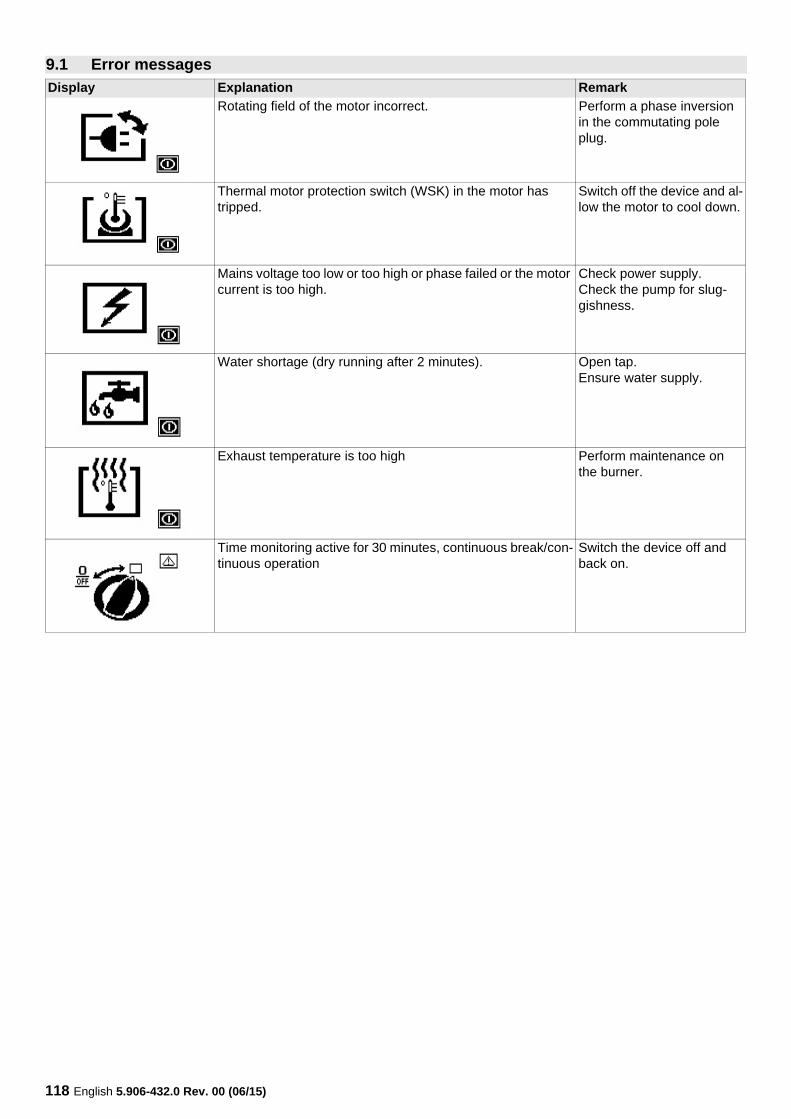
118 English 5.906-432.0 Rev. 00 (06/15)
9.1 Error messagesDisplay Explanation Remark
Rotating field of the motor incorrect. Perform a phase inversion in the commutating pole plug.
Thermal motor protection switch (WSK) in the motor has tripped.
Switch off the device and al-low the motor to cool down.
Mains voltage too low or too high or phase failed or the motor current is too high.
Check power supply.Check the pump for slug-gishness.
Water shortage (dry running after 2 minutes). Open tap.Ensure water supply.
Exhaust temperature is too high Perform maintenance on the burner.
Time monitoring active for 30 minutes, continuous break/con-tinuous operation
Switch the device off and back on.
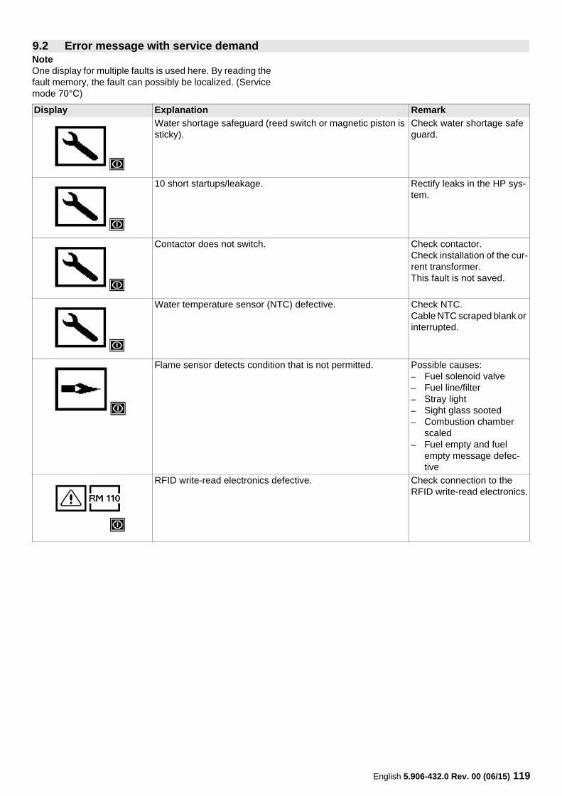
English 5.906-432.0 Rev. 00 (06/15) 119
NoteOne display for multiple faults is used here. By reading the fault memory, the fault can possibly be localized. (Service mode 70°C)
9.2 Error message with service demand
Display Explanation Remark
Water shortage safeguard (reed switch or magnetic piston is sticky).
Check water shortage safe guard.
10 short startups/leakage. Rectify leaks in the HP sys-tem.
Contactor does not switch. Check contactor.Check installation of the cur-rent transformer.This fault is not saved.
Water temperature sensor (NTC) defective. Check NTC.Cable NTC scraped blank or interrupted.
Flame sensor detects condition that is not permitted. Possible causes:– Fuel solenoid valve– Fuel line/filter– Stray light– Sight glass sooted– Combustion chamber
scaled– Fuel empty and fuel
empty message defec-tive
RFID write-read electronics defective. Check connection to the RFID write-read electronics.
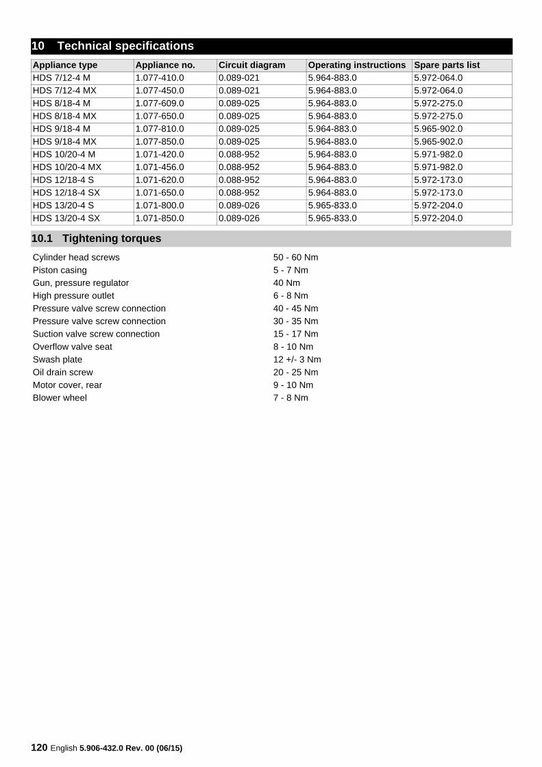
120 English 5.906-432.0 Rev. 00 (06/15)
10 Technical specifications
Appliance type Appliance no. Circuit diagram Operating instructions Spare parts list
HDS 7/12-4 M 1.077-410.0 0.089-021 5.964-883.0 5.972-064.0
HDS 7/12-4 MX 1.077-450.0 0.089-021 5.964-883.0 5.972-064.0
HDS 8/18-4 M 1.077-609.0 0.089-025 5.964-883.0 5.972-275.0
HDS 8/18-4 MX 1.077-650.0 0.089-025 5.964-883.0 5.972-275.0
HDS 9/18-4 M 1.077-810.0 0.089-025 5.964-883.0 5.965-902.0
HDS 9/18-4 MX 1.077-850.0 0.089-025 5.964-883.0 5.965-902.0
HDS 10/20-4 M 1.071-420.0 0.088-952 5.964-883.0 5.971-982.0
HDS 10/20-4 MX 1.071-456.0 0.088-952 5.964-883.0 5.971-982.0
HDS 12/18-4 S 1.071-620.0 0.088-952 5.964-883.0 5.972-173.0
HDS 12/18-4 SX 1.071-650.0 0.088-952 5.964-883.0 5.972-173.0
HDS 13/20-4 S 1.071-800.0 0.089-026 5.965-833.0 5.972-204.0
HDS 13/20-4 SX 1.071-850.0 0.089-026 5.965-833.0 5.972-204.0
10.1 Tightening torques
Cylinder head screws 50 - 60 Nm
Piston casing 5 - 7 Nm
Gun, pressure regulator 40 Nm
High pressure outlet 6 - 8 Nm
Pressure valve screw connection 40 - 45 Nm
Pressure valve screw connection 30 - 35 Nm
Suction valve screw connection 15 - 17 Nm
Overflow valve seat 8 - 10 Nm
Swash plate 12 +/- 3 Nm
Oil drain screw 20 - 25 Nm
Motor cover, rear 9 - 10 Nm
Blower wheel 7 - 8 Nm
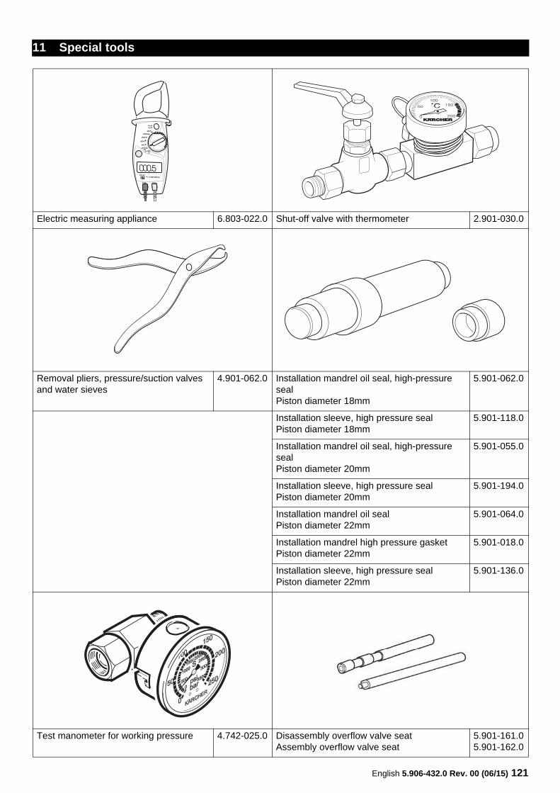
English 5.906-432.0 Rev. 00 (06/15) 121
11 Special tools
Electric measuring appliance 6.803-022.0 Shut-off valve with thermometer 2.901-030.0
Removal pliers, pressure/suction valves and water sieves
4.901-062.0 Installation mandrel oil seal, high-pressure sealPiston diameter 18mm
5.901-062.0
Installation sleeve, high pressure sealPiston diameter 18mm
5.901-118.0
Installation mandrel oil seal, high-pressure sealPiston diameter 20mm
5.901-055.0
Installation sleeve, high pressure sealPiston diameter 20mm
5.901-194.0
Installation mandrel oil sealPiston diameter 22mm
5.901-064.0
Installation mandrel high pressure gasketPiston diameter 22mm
5.901-018.0
Installation sleeve, high pressure sealPiston diameter 22mm
5.901-136.0
Test manometer for working pressure 4.742-025.0 Disassembly overflow valve seatAssembly overflow valve seat
5.901-161.05.901-162.0
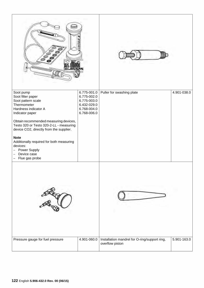
122 English 5.906-432.0 Rev. 00 (06/15)
Soot pumpSoot filter paperSoot pattern scaleThermometerHardness indicator AIndicator paper
Obtain recommended measuring devices, Testo 320 or Testo 320-2-LL - measuring device CO2, directly from the supplier.
NoteAdditionally required for both measuring devices:– Power Supply– Device case– Flue gas probe
6.775-001.06.775-002.06.775-003.06.432-029.06.768-004.06.768-006.0
Puller for swashing plate 4.901-038.0
Pressure gauge for fuel pressure 4.901-060.0 Installation mandrel for O-ring/support ring, overflow piston
5.901-163.0
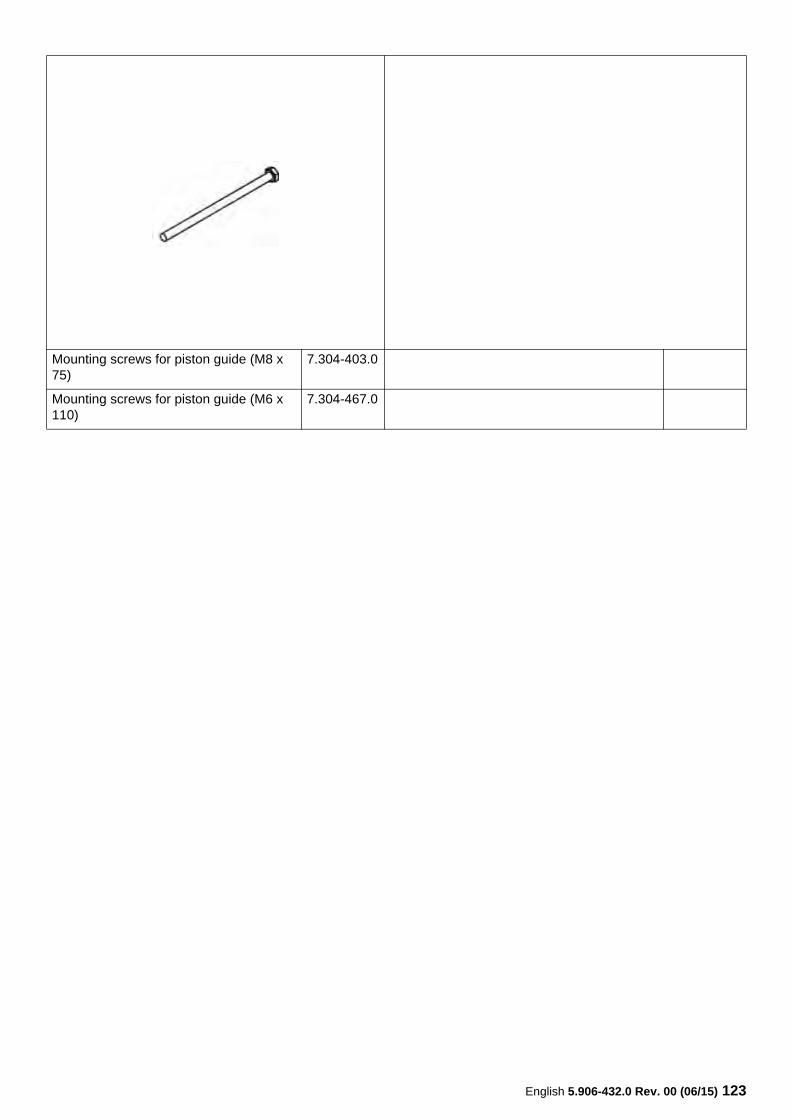
English 5.906-432.0 Rev. 00 (06/15) 123
Mounting screws for piston guide (M8 x 75)
7.304-403.0
Mounting screws for piston guide (M6 x 110)
7.304-467.0
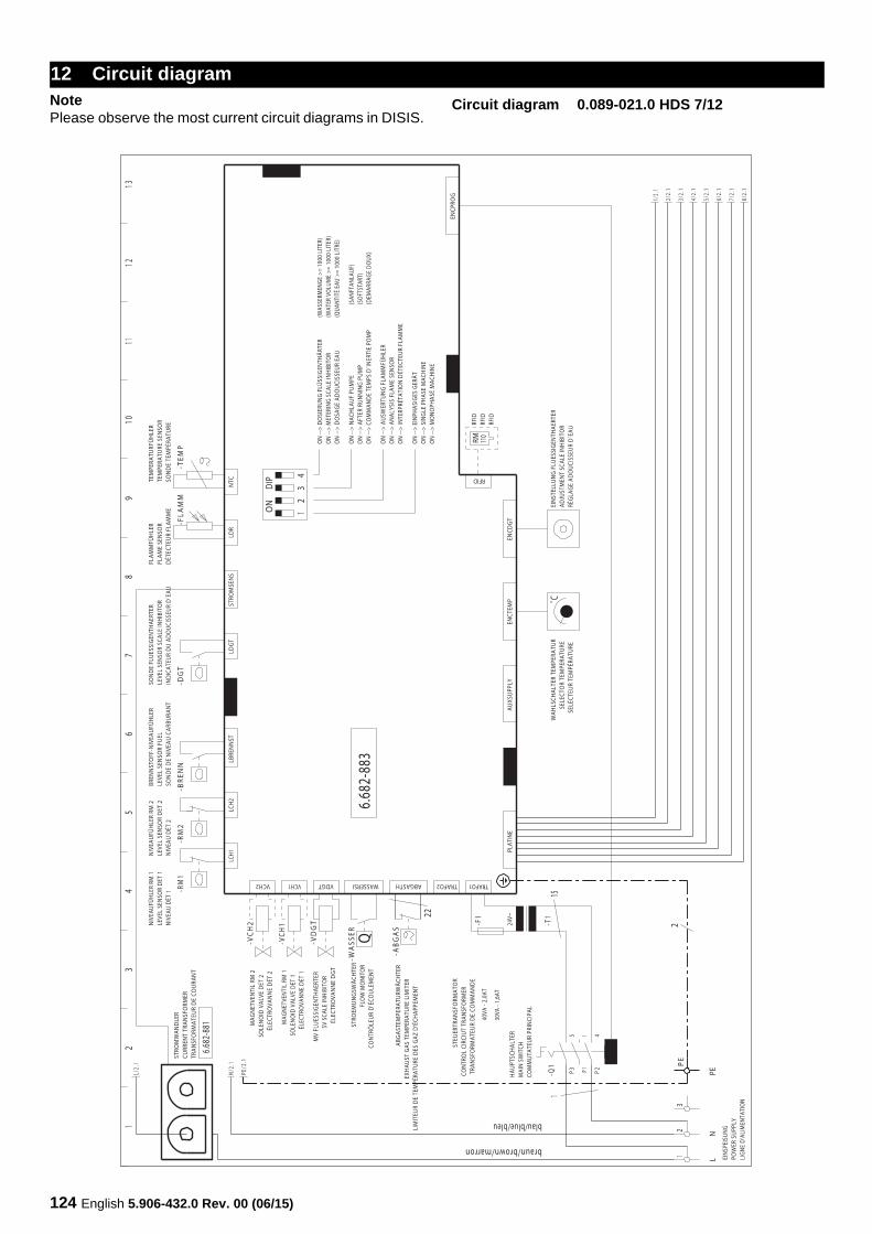
124 English 5.906-432.0 Rev. 00 (06/15)
NotePlease observe the most current circuit diagrams in DISIS.
12 Circuit diagram
Circuit diagram 0.089-021.0 HDS 7/12
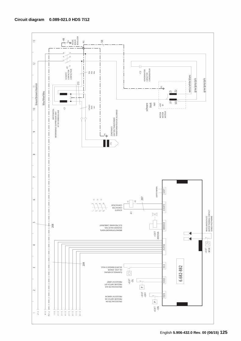
English 5.906-432.0 Rev. 00 (06/15) 125
Circuit diagram 0.089-021.0 HDS 7/12
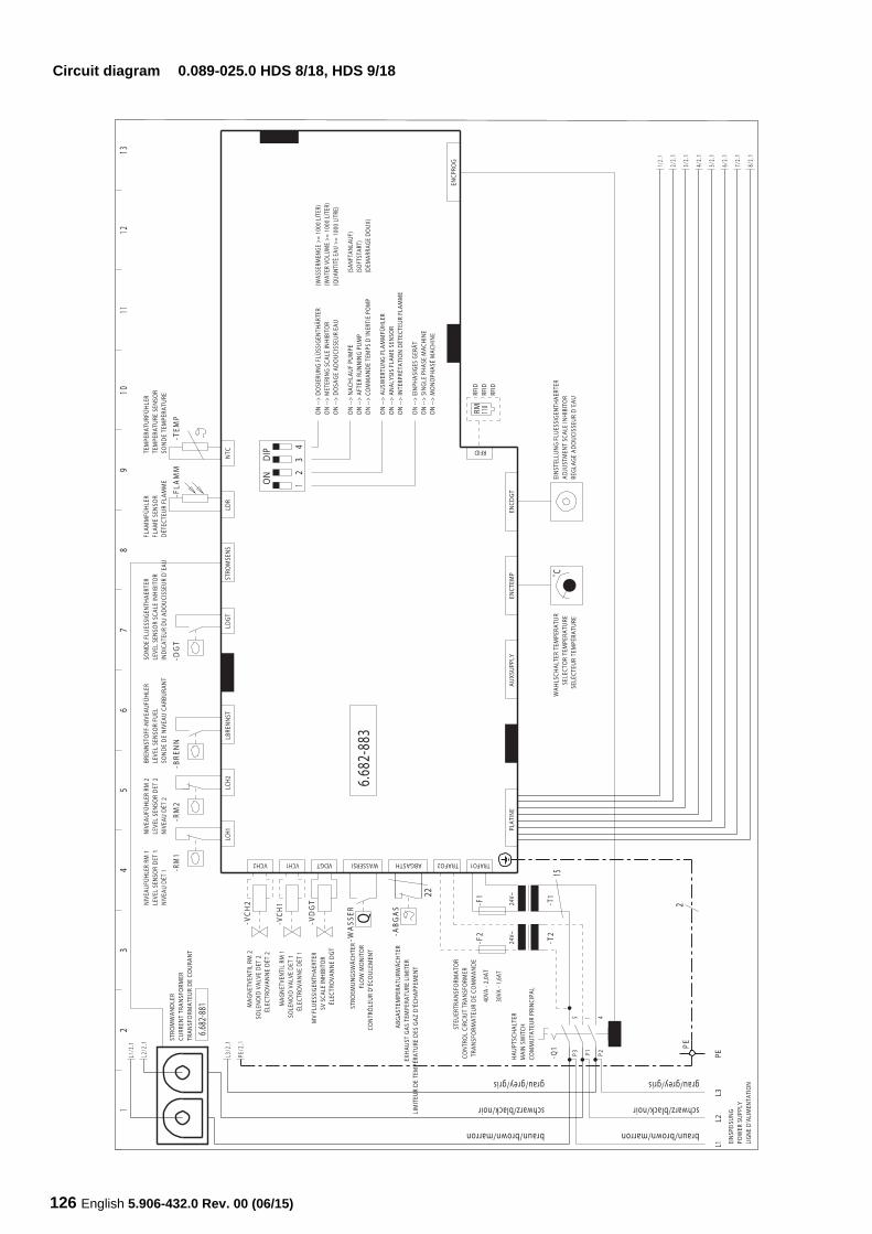
126 English 5.906-432.0 Rev. 00 (06/15)
Circuit diagram 0.089-025.0 HDS 8/18, HDS 9/18
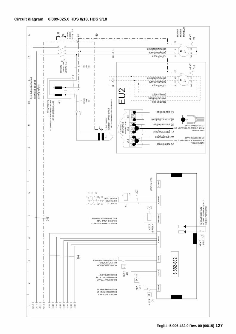
English 5.906-432.0 Rev. 00 (06/15) 127
Circuit diagram 0.089-025.0 HDS 8/18, HDS 9/18
12
34
56
78
910
1112
13L1
/1.2
L2/1
.2
L3/1
.2
PE/1
.2
1/1.
13
2/1.
13
4/1.
13
3/1.
13
5/1.
13
6/1.
13
7/1.
13
8/1.
13 +E
XT
-ON
DRUCKSCHALTER EINPRESSURE SWITCH ONPRESSOSTATMARCHE
P
+E
XT
-OF
F
DRUCKSCHALTERAUSPRESSURE SWITCH OFFPRESSOSTATARRET
P
+E
XT
-ÖL
ÖLMANGELSICHERUNGOILLEVELSENSORSÈCURITÉ MANQUE D´HUILE
+E
XT
-BR
EN
N
BRENNSTOFFMAGNETVENTILSOLENOID VALVE FUELÉLECTROVANNE CARBURANT
-K1
A1 A2
SCHUETZCONTACTORCONTACTEUR
+E
XT
-WS
KW
ICK
LUN
GS
SC
HU
TZ
MO
TO
RT
HE
RM
AL
CO
NTA
CT
SO
ND
E IP
SO
TH
ER
ME
-K1
6 5
4 3
2 1
-T1
PE
-C1
PEPE
+E
XT
-M1
U1
V1W
1P
E
W2
U2
V2
MO
TO
RM
OT
OR
MO
TE
UR
M 3~
+E
XT
-M1.
1
U1
V1W
1P
E
W2
U2
V2
M 3~
12
34
.12 .12 .125
6
1314
2122
6
DS
EIN
DS
AU
SO
ELS
IP
LAT
INE
VB
RE
NN
ST
SC
HU
ET
ZS
AN
FT
(SO
FTS
TAR
TER
)
208
209
6.68
2-88
2
SC
HU
ET
ZC
ON
TAC
TO
RC
ON
TAC
TE
UR
ZÜ
ND
TR
AF
OIG
NIT
ION
TR
AN
SF
OR
ME
RT
RA
NS
FO
RM
AT
EU
R D
EA
LLU
MA
GE
EN
TS
TOE
RT
EIL
INT
ER
FE
RE
NC
E S
UP
PR
ES
SIO
N U
NIT
KIT
DE
DE
BR
OU
ILLA
GE
213
schw
arz
blac
kno
ir
blau
blue
bleu
50
KE
SS
EL
BO
ILE
RB
OU
ILLE
UR
49
207
brau
n/br
own/
mar
ron
schw
arz/
blac
k/no
irgr
au/g
rey/
gris
gelb/yellow/jaune
weiss/white/blanc
gelb/yellow/jaune
L2L2
SC
HU
ET
ZC
ON
TAC
TO
RC
ON
TAC
TE
UR
V1: gelb/yellow/jaune
U2: weiss/white/blanc
ENTSTOERTEILINTERFERENCE SUPPRESSION UNITKITDE DEBROUILLAGE
ENTSTOERTEILINTERFERENCE SUPPRESSION UNITKITDE DEBROUILLAGE
3/L2
*)*)
*)
1/L1
5/L3
L1L3
L1L3
rot/red/rouge
schwarz/black/noir
rot/red/rouge
schwarz/black/noir
grau/grey/gris
blau/blue/bleu
U1: rot/red/rouge
W2: grau/grey/gris
V2: blau/blue/bleu
W1: schwarz/black/noir
EU
2
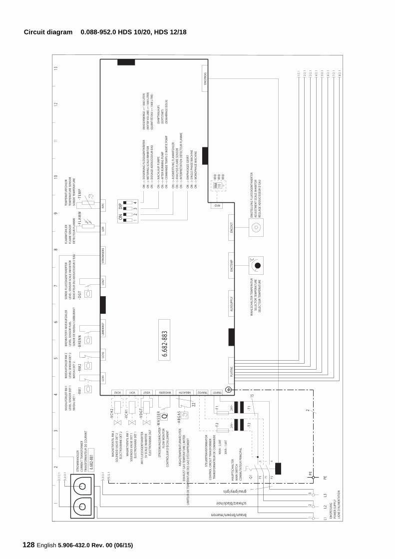
128 English 5.906-432.0 Rev. 00 (06/15)
Circuit diagram 0.088-952.0 HDS 10/20, HDS 12/18
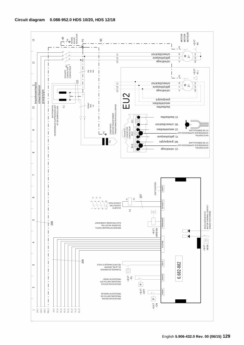
English 5.906-432.0 Rev. 00 (06/15) 129
Circuit diagram 0.088-952.0 HDS 10/20, HDS 12/18
12
34
56
78
910
1112
13L1
/1.2
L2/1
.2
L3/1
.2
PE/1
.2
1/1.
13
2/1.
13
4/1.
13
3/1.
13
5/1.
13
6/1.
13
7/1.
13
8/1.
13 +E
XT
-ON
DRUCKSCHALTER EINPRESSURE SWITCH ONPRESSOSTATMARCHE
P
+E
XT
-OF
F
DRUCKSCHALTERAUSPRESSURE SWITCH OFFPRESSOSTATARRET
P
+E
XT
-ÖL
ÖLMANGELSICHERUNGOILLEVELSENSORSÈCURITÉ MANQUE D´HUILE
+E
XT
-BR
EN
N
BRENNSTOFFMAGNETVENTILSOLENOID VALVE FUELÉLECTROVANNE CARBURANT
-K1
A1 A2
SCHUETZCONTACTORCONTACTEUR
+E
XT
-WS
KW
ICK
LUN
GS
SC
HU
TZ
MO
TO
RT
HE
RM
AL
CO
NTA
CT
SO
ND
E IP
SO
TH
ER
ME
-K1
6 5
4 3
2 1
-T1
PE
-C1
PEPE
+E
XT
-M1
U1
V1W
1P
E
W2
U2
V2
MO
TO
RM
OT
OR
MO
TE
UR
M 3~
+E
XT
-M1.
1
U1
V1W
1P
E
W2
U2
V2
M 3~
12
34
.12 .12 .125
6
1314
2122
6
DS
EIN
DS
AU
SO
ELS
IP
LAT
INE
VB
RE
NN
ST
SC
HU
ET
ZS
AN
FT
(SO
FTS
TAR
TER
)
208
209
6.68
2-88
2
SC
HU
ET
ZC
ON
TAC
TO
RC
ON
TAC
TE
UR
ZÜ
ND
TR
AF
OIG
NIT
ION
TR
AN
SF
OR
ME
RT
RA
NS
FO
RM
AT
EU
R D
EA
LLU
MA
GE
EN
TS
TOE
RT
EIL
INT
ER
FE
RE
NC
E S
UP
PR
ES
SIO
N U
NIT
KIT
DE
DE
BR
OU
ILLA
GE
213
schw
arz
blac
kno
ir
blau
blue
bleu
50
KE
SS
EL
BO
ILE
RB
OU
ILLE
UR
49
207
brau
n/br
own/
mar
ron
schw
arz/
blac
k/no
irgr
au/g
rey/
gris
gelb/yellow/jaune
weiss/white/blanc
gelb/yellow/jaune
L2L2
SC
HU
ET
ZC
ON
TAC
TO
RC
ON
TAC
TE
UR
V1: gelb/yellow/jaune
U2: weiss/white/blanc
ENTSTOERTEILINTERFERENCE SUPPRESSION UNITKITDE DEBROUILLAGE
ENTSTOERTEILINTERFERENCE SUPPRESSION UNITKITDE DEBROUILLAGE
3/L2
*)*)
*)
1/L1
5/L3
L1L3
L1L3
rot/red/rouge
schwarz/black/noir
rot/red/rouge
schwarz/black/noir
grau/grey/gris
blau/blue/bleu
U1: rot/red/rouge
W2: grau/grey/gris
V2: blau/blue/bleu
W1: schwarz/black/noir
EU
2
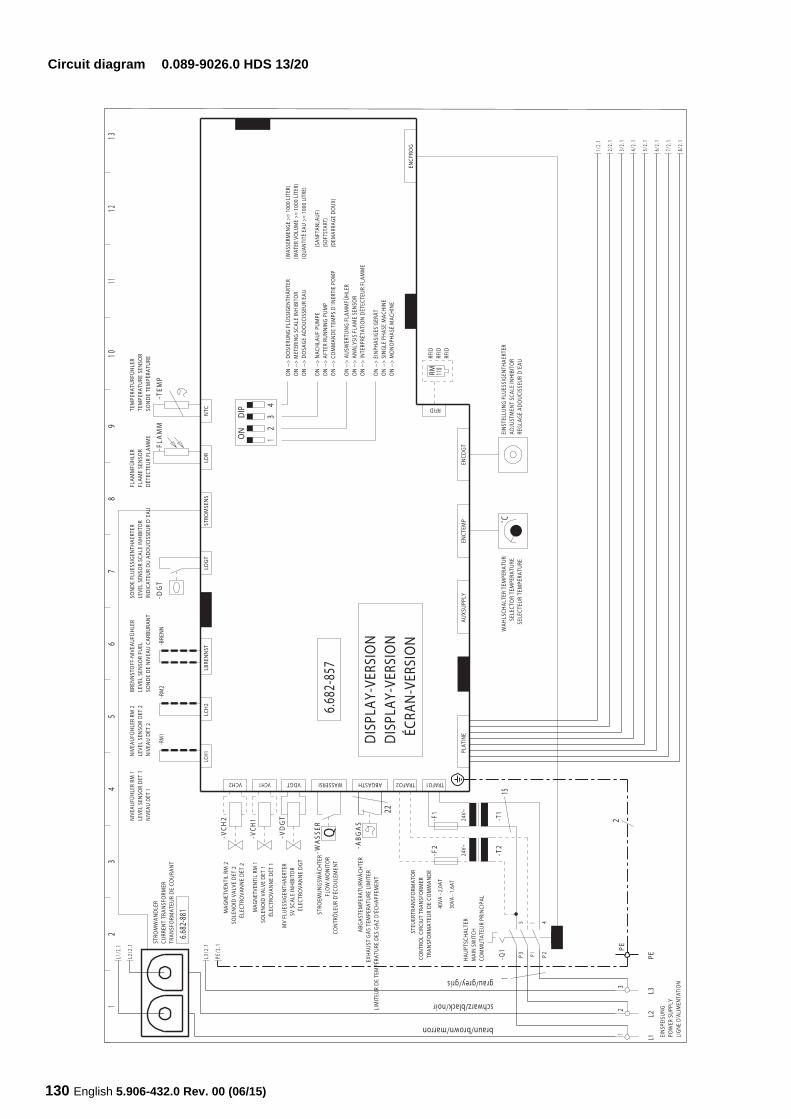
130 English 5.906-432.0 Rev. 00 (06/15)
Circuit diagram 0.089-9026.0 HDS 13/20
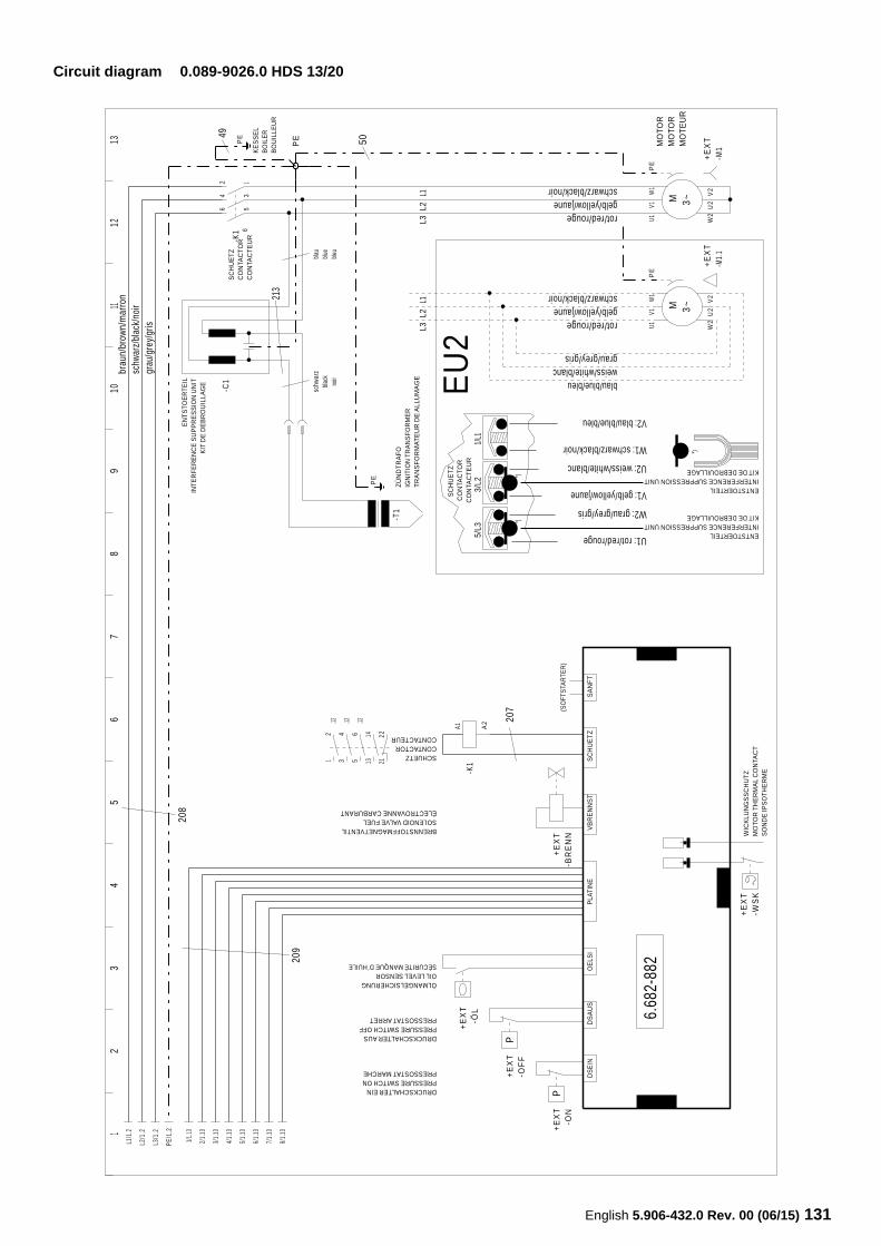
English 5.906-432.0 Rev. 00 (06/15) 131
Circuit diagram 0.089-9026.0 HDS 13/20
12
34
56
78
910
1112
13L1
/1.2
L2/1
.2
L3/1
.2
PE/1
.2
1/1.
13
2/1.
13
4/1.
13
3/1.
13
5/1.
13
6/1.
13
7/1.
13
8/1.
13 +E
XT
-ON
DRUCKSCHALTER EINPRESSURE SWITCH ONPRESSOSTATMARCHE
P
+E
XT
-OF
F
DRUCKSCHALTERAUSPRESSURE SWITCH OFFPRESSOSTATARRET
P
+E
XT
-ÖL
ÖLMANGELSICHERUNGOILLEVELSENSORSÈCURITÉ MANQUE D´HUILE
+E
XT
-BR
EN
N
BRENNSTOFFMAGNETVENTILSOLENOID VALVE FUELÉLECTROVANNE CARBURANT
-K1
A1 A2
SCHUETZCONTACTORCONTACTEUR
+E
XT
-WS
KW
ICK
LUN
GS
SC
HU
TZ
MO
TO
RT
HE
RM
AL
CO
NTA
CT
SO
ND
E IP
SO
TH
ER
ME
-K1
6 5
4 3
2 1
-T1
PE
-C1
PEPE
+E
XT
-M1
U1
V1W
1P
E
W2
U2
V2
MO
TO
RM
OT
OR
MO
TE
UR
M 3~
+E
XT
-M1.
1
U1
V1W
1P
E
W2
U2
V2
M 3~
12
34
.12 .12 .125
6
1314
2122
6
DS
EIN
DS
AU
SO
ELS
IP
LAT
INE
VB
RE
NN
ST
SC
HU
ET
ZS
AN
FT
(SO
FTS
TAR
TER
)
208
209
6.68
2-88
2
SC
HU
ET
ZC
ON
TAC
TO
RC
ON
TAC
TE
UR
ZÜ
ND
TR
AF
OIG
NIT
ION
TR
AN
SF
OR
ME
RT
RA
NS
FO
RM
AT
EU
R D
EA
LLU
MA
GE
EN
TS
TOE
RT
EIL
INT
ER
FE
RE
NC
E S
UP
PR
ES
SIO
N U
NIT
KIT
DE
DE
BR
OU
ILLA
GE
213
schw
arz
blac
kno
ir
blau
blue
bleu
50
KE
SS
EL
BO
ILE
RB
OU
ILLE
UR
49
207
brau
n/br
own/
mar
ron
schw
arz/
blac
k/no
irgr
au/g
rey/
gris
gelb/yellow/jaune
weiss/white/blanc
gelb/yellow/jaune
SC
HU
ET
ZC
ON
TAC
TO
RC
ON
TAC
TE
UR
V1: gelb/yellow/jaune
U2: weiss/white/blanc
ENTSTOERTEILINTERFERENCE SUPPRESSION UNITKITDE DEBROUILLAGE
ENTSTOERTEILINTERFERENCE SUPPRESSION UNITKITDE DEBROUILLAGE
3/L2
*)*)
*)
1/L1
5/L3
rot/red/rouge
schwarz/black/noir
rot/red/rouge
schwarz/black/noir
grau/grey/gris
blau/blue/bleu
U1: rot/red/rouge
W2: grau/grey/gris
V2: blau/blue/bleu
W1: schwarz/black/noir
L2L2
L1L3
L1L3
EU
2