hd 1080p ultra low-light poc camera - hikvision · this manual applies to hd 1080p ultra low-light...
TRANSCRIPT
0
HD 1080p Ultra Low-Light PoC Camera User Manual
UD02874B-A
1
User Manual
Thank you for purchasing our product. If there are any questions, or requests, do not hesitate to contact the dealer.
This manual applies to HD 1080p Ultra Low-Light PoC Camera.
This manual may contain several technically incorrect places or printing errors. The content is subject to change without notice, and the updates will be added to the new version of this manual. We will readily improve or update the products or procedures described in the manual.
Regulatory Information FCC Information
Please take attention that changes or modification not expressly approved by the party responsible for compliance could void the user’s authority to operate the equipment.
FCC compliance: This equipment has been tested and found to comply with the limits for a Class A digital device, pursuant to part 15 of the FCC Rules. These limits are designed to provide reasonable protection against harmful interference when the equipment is operated in a commercial environment. This equipment generates, uses, and can radiate radio frequency energy and, if not installed and used in accordance with the instruction manual, may cause harmful interference to radio communications. Operation of this equipment in a residential area is likely to cause harmful interference in which case the user will be required to correct the interference at his own expense.
FCC Conditions
This device complies with part 15 of the FCC Rules. Operation is subject to the following two conditions:
1. This device may not cause harmful interference.

2
2. This device must accept any interference received, including interference that may cause undesired operation.
EU Conformity Statement This product and - if applicable - the supplied accessories too are marked with "CE" and comply therefore with the applicable harmonized European standards listed under EMC Directive
2014/30/EU, the RoHS Directive 2011/65/EU. 2012/19/EU (WEEE directive): Products marked with this symbol cannot be disposed of as unsorted municipal waste in the European Union. For proper recycling, return this product to your local supplier upon the purchase of equivalent new equipment,
or dispose of it at designated collection points. For more information see: www.recyclethis.info. 2006/66/EC (battery directive): This product contains a battery
that cannot be disposed of as unsorted municipal waste in the European Union. See the product documentation for specific battery information. The battery is marked with this symbol, which may include lettering to indicate cadmium (Cd), lead
(Pb), or mercury (Hg). For proper recycling, return the battery to your supplier or to a designated collection point. For more information see: www.recyclethis.info. Industry Canada ICES-003 Compliance This device meets the CAN ICES-3 (A)/NMB-3(A) standards requirements.
3
Safety Instruction
These instructions are intended to ensure that user can use the product correctly to avoid danger or property loss.
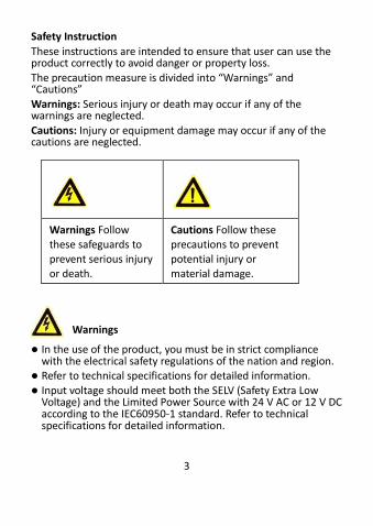
The precaution measure is divided into “Warnings” and “Cautions”
Warnings: Serious injury or death may occur if any of the warnings are neglected.
Cautions: Injury or equipment damage may occur if any of the cautions are neglected.
Warnings
In the use of the product, you must be in strict compliance with the electrical safety regulations of the nation and region.
Refer to technical specifications for detailed information.
Input voltage should meet both the SELV (Safety Extra Low Voltage) and the Limited Power Source with 24 V AC or 12 V DC according to the IEC60950-1 standard. Refer to technical specifications for detailed information.
Warnings Follow these safeguards to prevent serious injury or death.
Cautions Follow these precautions to prevent potential injury or material damage.
4
Do not connect several devices to one power adapter as adapter overload may cause over-heating or a fire hazard.
Make sure that the plug is firmly connected to the power socket.
When the product is mounted on wall or ceiling, the device shall be firmly fixed.
If smoke, odor or noise rise from the device, turn off the power at once and unplug the power cable, and then contact the service center.
If the product does not work properly, contact your dealer or the nearest service center. Never attempt to disassemble the camera yourself. (We shall not assume any responsibility for problems caused by unauthorized repair or maintenance.)
Cautions
Make sure the power supply voltage is correct before using the camera.
Do not drop the camera or subject it to physical shock. Do not touch senor modules with fingers. If cleaning is
necessary, use clean cloth with a bit of ethanol and wipe it gently. If the camera will not be used for an extended period, replace the lens cap to protect the sensor from dirt.
Do not aim the camera at the sun or extra bright places. Blooming or smearing may occur otherwise (which is not a malfunction), and affect the endurance of sensor at the same time.
The sensor may be burned out by a laser beam, so when any laser equipment is in using, make sure that the surface of sensor will not be exposed to the laser beam.
5
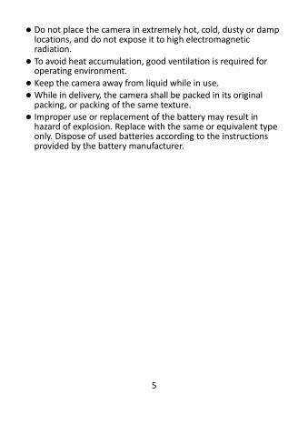
Do not place the camera in extremely hot, cold, dusty or damp locations, and do not expose it to high electromagnetic radiation.
To avoid heat accumulation, good ventilation is required for operating environment.
Keep the camera away from liquid while in use. While in delivery, the camera shall be packed in its original
packing, or packing of the same texture. Improper use or replacement of the battery may result in
hazard of explosion. Replace with the same or equivalent type only. Dispose of used batteries according to the instructions provided by the battery manufacturer.
6
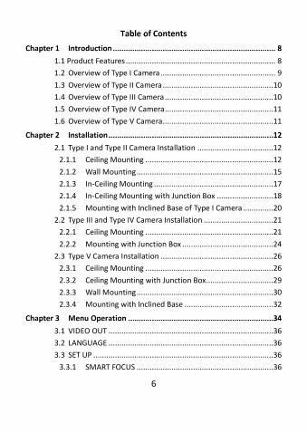
1.1 Product Features ..................................................................... 8 1.2 Overview of Type I Camera ..................................................... 9 1.3 Overview of Type II Camera ...................................................10 1.4 Overview of Type III Camera ..................................................10 1.5 Overview of Type IV Camera ..................................................11 1.6 Overview of Type V Camera...................................................11
2.1 Type I and Type II Camera Installation ...................................12 2.1.1 Ceiling Mounting ...........................................................12 2.1.2 Wall Mounting ...............................................................15 2.1.3 In-Ceiling Mounting .......................................................17 2.1.4 In-Ceiling Mounting with Junction Box ..........................18 2.1.5 Mounting with Inclined Base of Type I Camera ..............20
2.2 Type III and Type IV Camera Installation ................................21 2.2.1 Ceiling Mounting ...........................................................21 2.2.2 Mounting with Junction Box ..........................................24
2.3 Type V Camera Installation ....................................................26 2.3.1 Ceiling Mounting ...........................................................26 2.3.2 Ceiling Mounting with Junction Box...............................29 2.3.3 Wall Mounting ...............................................................30 2.3.4 Mounting with Inclined Base .........................................32
3.1 VIDEO OUT ............................................................................36 3.2 LANGUAGE ............................................................................36 3.3 SET UP ...................................................................................36
3.3.1 SMART FOCUS ...............................................................36
7
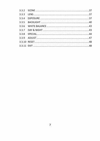
3.3.2 SCENE ............................................................................37 3.3.3 LENS ..............................................................................37 3.3.4 EXPOSURE .....................................................................37 3.3.5 BACKLIGHT ....................................................................40 3.3.6 WHITE BALANCE ............................................................43 3.3.7 DAY & NIGHT .................................................................43 3.3.8 SPECIAL..........................................................................44 3.3.9 ADJUST ..........................................................................47 3.3.10 RESET .............................................................................48 3.3.11 EXIT ...............................................................................48
8
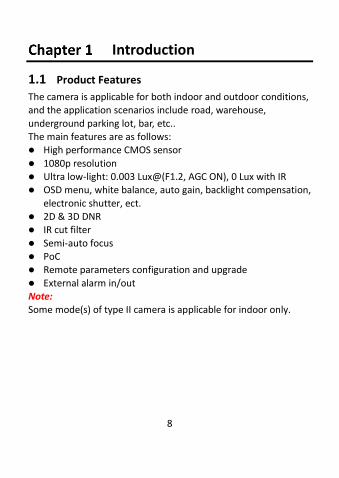
Introduction
1.1 Product Features
The camera is applicable for both indoor and outdoor conditions, and the application scenarios include road, warehouse,
underground parking lot, bar, etc.. The main features are as follows: High performance CMOS sensor
1080p resolution Ultra low-light: 0.003 Lux@(F1.2, AGC ON), 0 Lux with IR OSD menu, white balance, auto gain, backlight compensation,
electronic shutter, ect. 2D & 3D DNR IR cut filter
Semi-auto focus PoC Remote parameters configuration and upgrade
External alarm in/out Note: Some mode(s) of type II camera is applicable for indoor only.
9
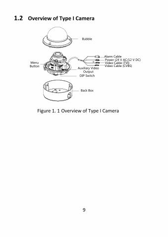
1.2 Overview of Type I Camera
Auxiliary Video Output
Menu Button
DIP Switch
Video Cable (CVBS)Video Cable (TVI)Power (24 V AC/12 V DC)Alarm Cable
Bubble
Back Box
ALA
RM
ING
OU
TG
Figure 1. 1 Overview of Type I Camera
10
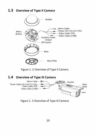
1.3 Overview of Type II Camera
Menu Button
Auxiliary Video Output
DIP Switch
Alarm Cable
Video Cable (CVBS)Video Cable (TVI)Power (24 V AC/12 V DC)
Base
Bubble
Base Plate
ALA
RM
ING
GO
UT
Figure 1. 2 Overview of Type II Camera
1.4 Overview of Type III Camera
BracketMain Body
Lens
Video Cable (CVBS)
Video Cable (TVI)Power Cable (24 V AC/12 V DC)
Alarm Cable
Figure 1. 3 Overview of Type III Camera
11
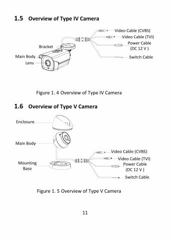
1.5 Overview of Type IV Camera
Video Cable (CVBS)
Video Cable (TVI)
Power Cable (DC 12 V )
Switch Cable
Bracket
Main Body
Lens
Figure 1. 4 Overview of Type IV Camera
1.6 Overview of Type V Camera
Enclosure
Main Body
Mounting Base
Video Cable (CVBS)
Video Cable (TVI)Power Cable
(DC 12 V )
Switch Cable
Figure 1. 5 Overview of Type V Camera
12
Installation
Before you start: Make sure that the device in the package is in good condition
and all the assembly parts are included.
Make sure that all the related equipment is power-off during the installation.
Check the specification of the products for the installation
environment. Check whether the power supply is matched with your
power output to avoid damage.
Make sure the wall is strong enough to withstand three times the weight of the camera and the mounting bracket.
If the wall is cement, insert expansion screws before
installing the camera. If the wall is wooden, use self-tapping screw to secure the camera.
If the product does not function properly, contact your
dealer or the nearest service center. Do not disassemble the camera for repair or maintenance by yourself.
2.1 Type I and Type II Camera Installation
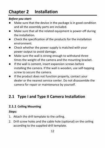
2.1.1 Ceiling Mounting
Steps:
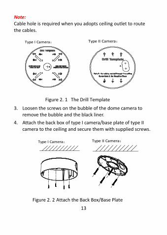
1. Attach the drill template to the celling.
2. Drill screw holes and the cable hole (optional) on the ceiling according to the supplied drill template.
13
Note: Cable hole is required when you adopts ceiling outlet to route
the cables.
Type I Camera:
Type II Camera:
Figure 2. 1 The Drill Template
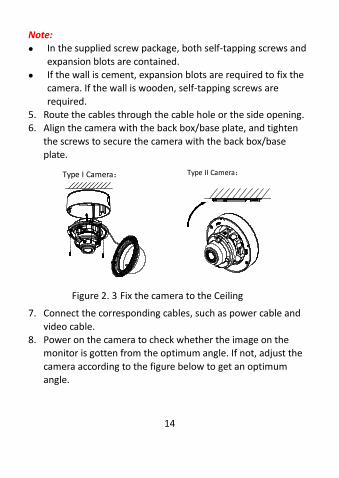
3. Loosen the screws on the bubble of the dome camera to remove the bubble and the black liner.
4. Attach the back box of type I camera/base plate of type II camera to the ceiling and secure them with supplied screws.
Type I Camera:
Type II Camera:
Figure 2. 2 Attach the Back Box/Base Plate
14
Note: In the supplied screw package, both self-tapping screws and
expansion blots are contained. If the wall is cement, expansion blots are required to fix the
camera. If the wall is wooden, self-tapping screws are
required. 5. Route the cables through the cable hole or the side opening. 6. Align the camera with the back box/base plate, and tighten
the screws to secure the camera with the back box/base plate.
Type I Camera:
Type II Camera:
Figure 2. 3 Fix the camera to the Ceiling
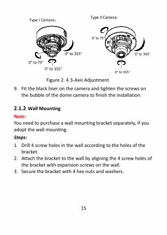
7. Connect the corresponding cables, such as power cable and
video cable. 8. Power on the camera to check whether the image on the
monitor is gotten from the optimum angle. If not, adjust the
camera according to the figure below to get an optimum angle.
15
Type I Camera:
0° to 355°
0° to 355°
0° to 75°
0° to 355°
0° to 340°
0° to 75°
Type II Camera:
Figure 2. 4 3-Axis Adjustment
9. Fit the black liner on the camera and tighten the screws on the bubble of the dome camera to finish the installation.
2.1.2 Wall Mounting
Note: You need to purchase a wall mounting bracket separately, if you
adopt the wall mounting.
Steps:
1. Drill 4 screw holes in the wall according to the holes of the bracket.
2. Attach the bracket to the wall by aligning the 4 screw holes of
the bracket with expansion screws on the wall. 3. Secure the bracket with 4 hex nuts and washers.
16
Type I Camera
Type II Camera
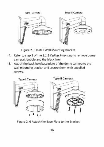
Figure 2. 5 Install Wall Mounting Bracket
4. Refer to step 3 of the 2.1.1 Ceiling Mounting to remove dome camera’s bubble and the black liner.
5. Attach the back box/base plate of the dome camera to the wall mounting bracket and secure them with supplied screws.
Type I Camera
Type II Camera
Figure 2. 6 Attach the Base Plate to the Bracket
17
6. Route the cables through the bracket. 7. Repeat steps 6 to 9 of the 2.1.1 Ceiling Mounting to complete
the installation.
2.1.3 In-Ceiling Mounting
Note:
You need to purchase an in-ceiling mounting bracket separately if you adopt the in-ceiling mounting.
Steps:
1. Attach the drill template on the ceiling. 2. Drill the screw holes and cable holes (optional) in the ceiling
according to the supplied drill template. Note: Cable hole is required when adopting ceiling outlet to route the
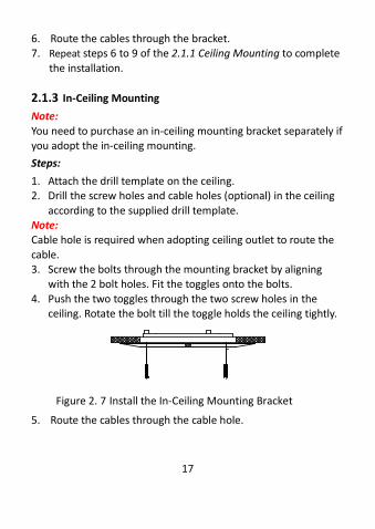
cable. 3. Screw the bolts through the mounting bracket by aligning
with the 2 bolt holes. Fit the toggles onto the bolts.
4. Push the two toggles through the two screw holes in the ceiling. Rotate the bolt till the toggle holds the ceiling tightly.
Figure 2. 7 Install the In-Ceiling Mounting Bracket
5. Route the cables through the cable hole.
18
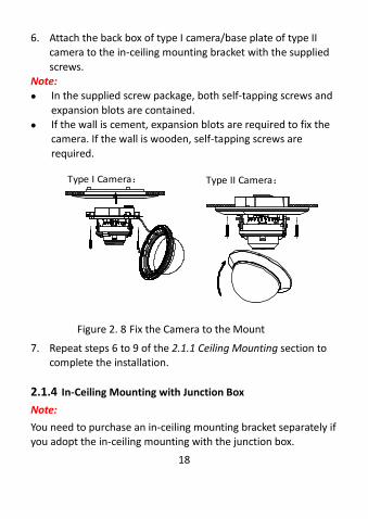
6. Attach the back box of type I camera/base plate of type II camera to the in-ceiling mounting bracket with the supplied
screws. Note: In the supplied screw package, both self-tapping screws and
expansion blots are contained. If the wall is cement, expansion blots are required to fix the
camera. If the wall is wooden, self-tapping screws are
required.
Type I Camera:
Type II Camera:
Figure 2. 8 Fix the Camera to the Mount
7. Repeat steps 6 to 9 of the 2.1.1 Ceiling Mounting section to complete the installation.
2.1.4 In-Ceiling Mounting with Junction Box
Note:
You need to purchase an in-ceiling mounting bracket separately if you adopt the in-ceiling mounting with the junction box.
19
Steps:
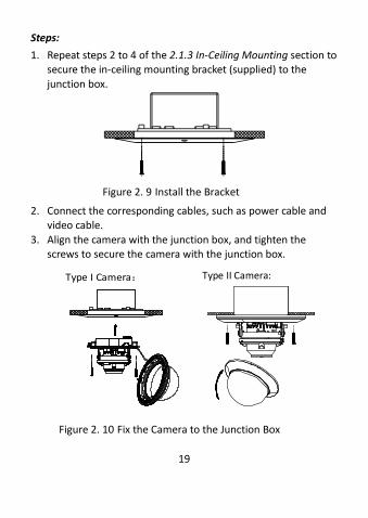
1. Repeat steps 2 to 4 of the 2.1.3 In-Ceiling Mounting section to secure the in-ceiling mounting bracket (supplied) to the
junction box.
Figure 2. 9 Install the Bracket
2. Connect the corresponding cables, such as power cable and video cable.
3. Align the camera with the junction box, and tighten the screws to secure the camera with the junction box.
Type I Camera:
Type II Camera:
Figure 2. 10 Fix the Camera to the Junction Box
20
4. Repeat the steps 6 to 9 of the 2.1.1 Ceiling Mounting section to complete the installation.
2.1.5 Mounting with Inclined Base of Type I Camera
Note:
You need to purchase an inclined base separately if you adopt the mounting with an inclined base.
Steps:
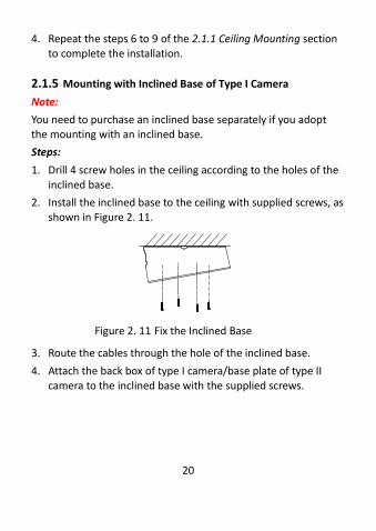
1. Drill 4 screw holes in the ceiling according to the holes of the inclined base.
2. Install the inclined base to the ceiling with supplied screws, as shown in Figure 2. 11.
Figure 2. 11 Fix the Inclined Base
3. Route the cables through the hole of the inclined base.
4. Attach the back box of type I camera/base plate of type II camera to the inclined base with the supplied screws.
21
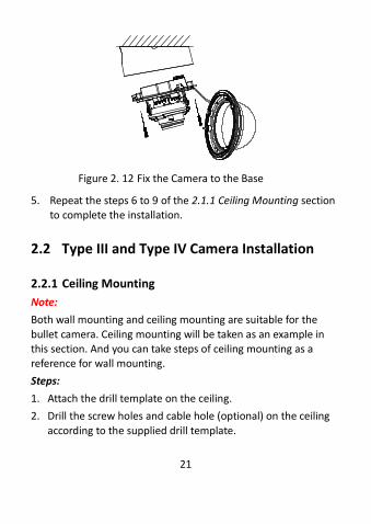
Figure 2. 12 Fix the Camera to the Base
5. Repeat the steps 6 to 9 of the 2.1.1 Ceiling Mounting section to complete the installation.
2.2 Type III and Type IV Camera Installation
2.2.1 Ceiling Mounting
Note:
Both wall mounting and ceiling mounting are suitable for the
bullet camera. Ceiling mounting will be taken as an example in this section. And you can take steps of ceiling mounting as a reference for wall mounting.
Steps:
1. Attach the drill template on the ceiling.
2. Drill the screw holes and cable hole (optional) on the ceiling
according to the supplied drill template.
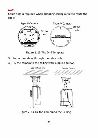
22
Note: Cable hole is required when adopting ceiling outlet to route the
cable.
120° 120°
Screw Hole
Type III Camera Screw Hole
Type IV Camera
Figure 2. 13 The Drill Template
3. Route the cables through the cable hole.
4. Fix the camera to the ceiling with supplied screws.
Type III Camera
Type IV Camera
Figure 2. 14 Fix the Camera to the Ceiling
23
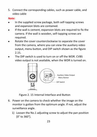
5. Connect the corresponding cables, such as power cable, and video cable
Note:
In the supplied screw package, both self-tapping screws and expansion blots are contained.
If the wall is cement, expansion blots are required to fix the
camera. If the wall is wooden, self-tapping screws are required.
Rotate the cover counterclockwise to separate the cover
from the camera, where you can view the auxiliary video output, menu button, and DIP switch shown as the figure 2.15.
The DIP switch is used to turn on or off the WDR. CVBS video output is not available, when the WDR is turned on.
Menu Button
Auxiliary Video Output
DIP Switch
Figure 2. 15 Internal Interface and Button
6. Power on the camera to check whether the image on the monitor is gotten from the optimum angle. If not, adjust the
surveillance angle.
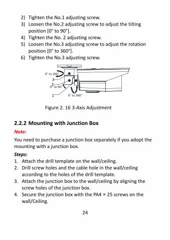
1) Loosen the No.1 adjusting screw to adjust the pan position [0° to 360°].
24
2) Tighten the No.1 adjusting screw. 3) Loosen the No.2 adjusting screw to adjust the tilting
position [0° to 90°]. 4) Tighten the No. 2 adjusting screw. 5) Loosen the No.3 adjusting screw to adjust the rotation
position [0° to 360°]. 6) Tighten the No.3 adjusting screw.
0° to 90°
0° to 360°
0° to 360°
32
1
Figure 2. 16 3-Axis Adjustment
2.2.2 Mounting with Junction Box
Note:
You need to purchase a junction box separately if you adopt the mounting with a junction box.
Steps:
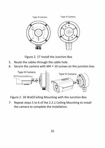
1. Attach the drill template on the wall/ceiling. 2. Drill screw holes and the cable hole in the wall/ceiling
according to the holes of the drill template.
3. Attach the junction box to the wall/ceiling by aligning the screw holes of the junction box.
4. Secure the junction box with the PA4 × 25 screws on the
wall/Ceiling.
25
Type III Camera Type IV Camera
Figure 2. 17 Install the Junction Box
5. Route the cables through the cable hole. 6. Secure the camera with M4 × 10 screws on the junction box.
Type III Camera
Type IV Camera
Figure 2. 18 Wall/Ceiling Mounting with the Junction Box
7. Repeat steps 5 to 6 of the 2.2.1 Ceiling Mounting to install the camera to complete the installation.
26
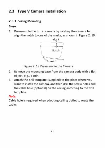
2.3 Type V Camera Installation
2.3.1 Ceiling Mounting
Steps:
1. Disassemble the turret camera by rotating the camera to align the notch to one of the marks, as shown in Figure 2. 19.
Mark
Notch
Figure 2. 19 Disassemble the Camera
2. Remove the mounting base from the camera body with a flat object, e.g., a coin.
3. Attach the drill template (supplied) to the place where you
want to install the camera, and then drill the screw holes and the cable hole (optional) on the ceiling according to the drill template.
Note: Cable hole is required when adopting ceiling outlet to route the cable.
27
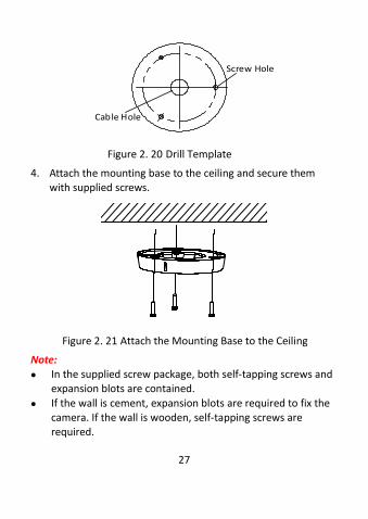
Screw Hole
Cable Hole
Figure 2. 20 Drill Template
4. Attach the mounting base to the ceiling and secure them with supplied screws.
Figure 2. 21 Attach the Mounting Base to the Ceiling
Note: In the supplied screw package, both self-tapping screws and
expansion blots are contained.
If the wall is cement, expansion blots are required to fix the camera. If the wall is wooden, self-tapping screws are required.
28
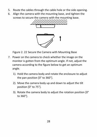
5. Route the cables through the cable hole or the side opening. 6. Align the camera with the mounting base, and tighten the
screws to secure the camera with the mounting base.
Figure 2. 22 Secure the Camera with Mounting Base
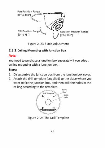
7. Power on the camera to check whether the image on the monitor is gotten from the optimum angle. If not, adjust the
camera according to the figure below to get an optimum angle.
1). Hold the camera body and rotate the enclosure to adjust
the pan position [0° to 360°].
2). Move the camera body up and down to adjust the tilt position [0° to 75°].
3). Rotate the camera body to adjust the rotation position [0° to 360°].
29
Tilt Position Range[0°to 75°]
Pan Position Range[0° to 360°]
Rotation Position Range[0°to 360°]
Figure 2. 23 3-axis Adjustment
2.3.2 Ceiling Mounting with Junction Box
Note:
You need to purchase a junction box separately if you adopt celling mounting with a junction box.
Steps:
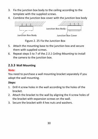
1. Disassemble the junction box from the junction box cover.
2. Attach the drill template (supplied) to the place where you want to fix the junction box, and then drill the holes in the ceiling according to the template.
Screw Hole
Cable Hole
Figure 2. 24 The Drill Template
30
3. Fix the junction box body to the ceiling according to the template with the supplied screws.
4. Combine the junction box cover with the junction box body
Junction Box Body
Junction Box Body
Junction Box Cover
Figure 2. 25 Fix the Junction Box
5. Attach the mounting base to the junction box and secure them with supplied screws.
6. Repeat steps 5 to 7 of the 2.3.1 Ceiling Mounting to install the camera to the junction box.
2.3.3 Wall Mounting
Note: You need to purchase a wall mounting bracket separately if you adopt the wall mounting.
Steps:
1. Drill 4 screw holes in the wall according to the holes of the
bracket. 2. Attach the bracket to the wall by aligning the 4 screw holes of
the bracket with expansion screws on the wall.
3. Secure the bracket with 4 hex nuts and washers.
31
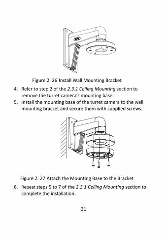
Figure 2. 26 Install Wall Mounting Bracket
4. Refer to step 2 of the 2.3.1 Ceiling Mounting section to remove the turret camera’s mounting base.
5. Install the mounting base of the turret camera to the wall mounting bracket and secure them with supplied screws.
Figure 2. 27 Attach the Mounting Base to the Bracket
6. Repeat steps 5 to 7 of the 2.3.1 Ceiling Mounting section to
complete the installation.
32
2.3.4 Mounting with Inclined Base
Note: You need to purchase an inclined base separately if you adopt
the mounting with an inclined base. Steps:
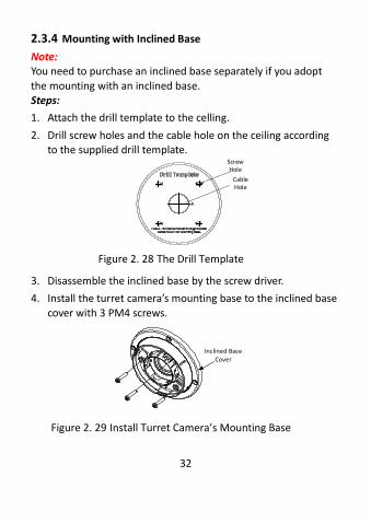
1. Attach the drill template to the celling.
2. Drill screw holes and the cable hole on the ceiling according to the supplied drill template.
Screw Hole
Cable Hole
Figure 2. 28 The Drill Template
3. Disassemble the inclined base by the screw driver.
4. Install the turret camera’s mounting base to the inclined base
cover with 3 PM4 screws.
Inclined Base Cover
Figure 2. 29 Install Turret Camera’s Mounting Base
33
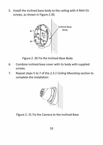
5. Install the inclined base body to the ceiling with 4 PA4×25 screws, as shown in Figure 2.30.
Inclined Base Body
Figure 2. 30 Fix the Inclined Base Body
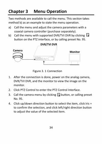
6. Combine inclined base cover with its body with supplied screws.
7. Repeat steps 5 to 7 of the 2.3.1 Ceiling Mounting section to
complete the installation
Figure 2. 31 Fix the Camera to the Inclined Base
34
Menu Operation
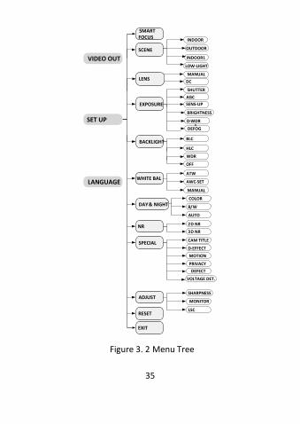
Two methods are available to call the menu. This section takes method b) as an example to state the menu operation.
a) Call the menu and adjust the camera parameters with a
coaxial camera controller (purchase separately). b) Call the menu with supported DVR/TVI DVR by clicking
button on the PTZ interface, or by calling preset No. 95.
Camera
DVR/TVI DVR
Monitor
Figure 3. 1 Connection
1. After the connection is done, power on the analog camera, DVR/TVI DVR, and the monitor to view the image on the monitor.
2. Click PTZ Control to enter the PTZ Control Interface.
3. Call the camera menu by clicking button, or calling preset
No. 95.
4. Click up/down direction button to select the item, click Iris + to confirm the selection, and click left/right direction button to adjust the value of the selected item.
35
SMART FOCUS
SCENE
LENS
INDOOR
SET UP
VIDEO OUT
LANGUAGE
EXPOSURE
BACKLIGHT
WHITE BAL
DAY & NIGHT
NR
SPECIAL
ADJUST
RESET
EXIT
OUTDOOR
INDOOR1
LOW-LIGHT
MANUAL
SHUTTER
AGC
BRIGHTNESS
D-WDR
BLC
WDR
ATW
AWC-SET
MANUAL
COLOR
B/W
AUTO
2D NR
3D NR
CAM TITLE
D-EFFECT
MOTION
PRIVACY
VOLTAGE DET.
SHARPNESS
MONITOR
LSC
HLC
OFF
DC
DEFOG
DEFECT
SENS-UP
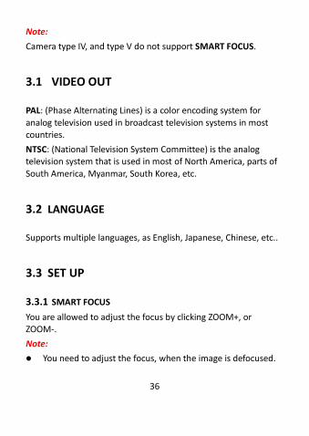
Figure 3. 2 Menu Tree
36
Note:
Camera type IV, and type V do not support SMART FOCUS.
3.1 VIDEO OUT
PAL: (Phase Alternating Lines) is a color encoding system for
analog television used in broadcast television systems in most countries.
NTSC: (National Television System Committee) is the analog television system that is used in most of North America, parts of
South America, Myanmar, South Korea, etc.
3.2 LANGUAGE
Supports multiple languages, as English, Japanese, Chinese, etc..
3.3 SET UP
3.3.1 SMART FOCUS
You are allowed to adjust the focus by clicking ZOOM+, or ZOOM-.
Note:
You need to adjust the focus, when the image is defocused.
37
Type IV and Type V cameras do not support SMART FOCUS.
3.3.2 SCENE
You can select INDOOR, OUTDOOR, INDOOR 1, and LOW LIGHT as the working environment.
INDOOR: Applicable to the indoor environment whose color temperature changes are relatively slight.
OUTDOOR: Applicable to the outdoor environment whose color
temperature changes are relatively obvious.
INDOOR1: Applicable to the indoor environment with the strong light. Under this circumstance, WDR is ON by default.
LOW LIGHT: Applicable to the environment with the low light. Under this circumstance, the slow shutter is ON by default to
receive more light.
3.3.3 LENS
The camera is equipped with manual lens, and DC lens.
Indoor mode and outdoor mode are available for the DC lens.
Click IRIS SCAN to initialize the lens.
3.3.4 EXPOSURE
Exposure describes the brightness-related parameters. You can adjust the image brightness by the SHUTTER, AGC, SENS-UP,
BRIGHTNESS, and D-WDR in different light conditions.
38
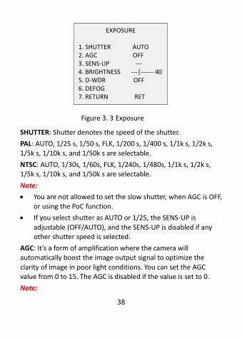
EXPOSURE
1. SHUTTER AUTO2. AGC OFF3. SENS-UP ---4. BRIGHTNESS ---|------ 405. D-WDR OFF6. DEFOG7. RETURN RET
Figure 3. 3 Exposure
SHUTTER: Shutter denotes the speed of the shutter.
PAL: AUTO, 1/25 s, 1/50 s, FLK, 1/200 s, 1/400 s, 1/1k s, 1/2k s,
1/5k s, 1/10k s, and 1/50k s are selectable.
NTSC: AUTO, 1/30s, 1/60s, FLK, 1/240s, 1/480s, 1/1k s, 1/2k s, 1/5k s, 1/10k s, and 1/50k s are selectable.
Note:
You are not allowed to set the slow shutter, when AGC is OFF, or using the PoC function.
If you select shutter as AUTO or 1/25, the SENS-UP is
adjustable (OFF/AUTO), and the SENS-UP is disabled if any other shutter speed is selected.
AGC: It’s a form of amplification where the camera will automatically boost the image output signal to optimize the
clarity of image in poor light conditions. You can set the AGC value from 0 to 15. The AGC is disabled if the value is set to 0.
Note:
39
The noise will be amplified if the AGC is on.
SENS-UP: Sense up increases the exposure on a signal frame, which makes a camera more sensitive to light so it can produce
images even in low lux conditions. You can set the SENS-UP as OFF or AUTO according to different light conditions.
OFF: SENS-UP function is disabled.
AUTO: The SENS-UP function will atomically adjust itself to x2, x4, x6, x8, x10, x15, x20, x25, and x30 according to the different light
conditions.
BRIGHTNESS: Brightness refers to the brightness of the image. You can set the brightness value from 1 to 100 to darken or brighten the image. The higher the value, the brighter the image
is.
D-WDR: The digital wide dynamic range helps the camera provide clear images even under backlight circumstances. When there are both very bright and very dark areas simultaneously in
the field of view, D-WDR balances the brightness level of the whole image and provide clear images with details.
Set the D-WDR as ON to improve the image quality under the backlight environment.
Set the D-WDR as OFF to disable the function.
DEFOG: DEFOG is used in special environment such as the foggy
or rainy weather or in high illumination, in which the dynamic range is lower than that in the ordinary environment and the image always appear hazy. Enable the defog function can
enhance the subtle details so that the image appears clearer.
40
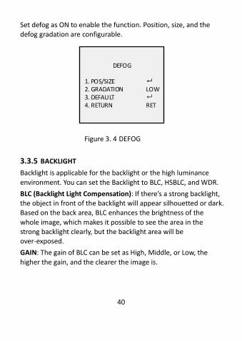
Set defog as ON to enable the function. Position, size, and the defog gradation are configurable.
DEFOG
1. POS/SIZE 2. GRADATION LOW3. DEFAULT 4. RETURN RET
Figure 3. 4 DEFOG
3.3.5 BACKLIGHT
Backlight is applicable for the backlight or the high luminance
environment. You can set the Backlight to BLC, HSBLC, and WDR.
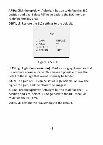
BLC (Backlight Light Compensation): If there’s a strong backlight, the object in front of the backlight will appear silhouetted or dark. Based on the back area, BLC enhances the brightness of the
whole image, which makes it possible to see the area in the strong backlight clearly, but the backlight area will be over-exposed.
GAIN: The gain of BLC can be set as High, Middle, or Low, the
higher the gain, and the clearer the image is.
41
AREA: Click the up/down/left/right button to define the BLC position and size. Select RET to go back to the BLC menu or
re-define the BLC area.
DEFAULT: Restore the BLC settings to the default.
BLC
1. GAIN MIDDLE2. AREA 3. DEFAUT 4. RETURN RET
Figure 3. 5 BLC
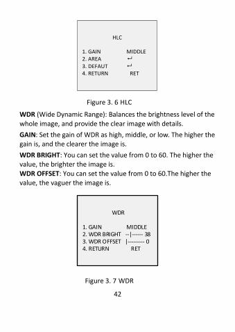
HLC (High Light Compensation): Masks strong light sources that usually flare across a scene. This makes it possible to see the detail of the image that would normally be hidden.
GAIN: The gain of HLC can be set as High, Middle, or Low, the higher the gain, and the clearer the image is.
AREA: Click the up/down/left/right button to define the HLC
position and size. Select RET to go back to the HLC menu or re-define the BLC area.
DEFAULT: Restore the HLC settings to the default.
42
HLC
1. GAIN MIDDLE2. AREA 3. DEFAUT 4. RETURN RET
Figure 3. 6 HLC
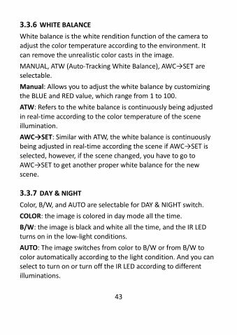
WDR (Wide Dynamic Range): Balances the brightness level of the
whole image, and provide the clear image with details.
GAIN: Set the gain of WDR as high, middle, or low. The higher the gain is, and the clearer the image is.
WDR BRIGHT: You can set the value from 0 to 60. The higher the value, the brighter the image is.
WDR OFFSET: You can set the value from 0 to 60.The higher the value, the vaguer the image is.
WDR
1. GAIN MIDDLE2. WDR BRIGHT --|------ 383. WDR OFFSET |--------- 0 4. RETURN RET
Figure 3. 7 WDR
43
3.3.6 WHITE BALANCE
White balance is the white rendition function of the camera to adjust the color temperature according to the environment. It
can remove the unrealistic color casts in the image.
MANUAL, ATW (Auto-Tracking White Balance), AWC→SET are selectable.
Manual: Allows you to adjust the white balance by customizing the BLUE and RED value, which range from 1 to 100.
ATW: Refers to the white balance is continuously being adjusted
in real-time according to the color temperature of the scene illumination.
AWC→SET: Similar with ATW, the white balance is continuously being adjusted in real-time according the scene if AWC→SET is
selected, however, if the scene changed, you have to go to AWC→SET to get another proper white balance for the new scene.
3.3.7 DAY & NIGHT
Color, B/W, and AUTO are selectable for DAY & NIGHT switch.
COLOR: the image is colored in day mode all the time.
B/W: the image is black and white all the time, and the IR LED turns on in the low-light conditions.
AUTO: The image switches from color to B/W or from B/W to
color automatically according to the light condition. And you can select to turn on or turn off the IR LED according to different illuminations.
44
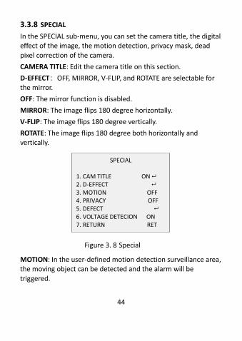
3.3.8 SPECIAL
In the SPECIAL sub-menu, you can set the camera title, the digital effect of the image, the motion detection, privacy mask, dead
pixel correction of the camera.
CAMERA TITLE: Edit the camera title on this section.
D-EFFECT:OFF, MIRROR, V-FLIP, and ROTATE are selectable for the mirror.
OFF: The mirror function is disabled.
MIRROR: The image flips 180 degree horizontally.
V-FLIP: The image flips 180 degree vertically.
ROTATE: The image flips 180 degree both horizontally and vertically.
SPECIAL
1. CAM TITLE ON
2. D-EFFECT 3. MOTION OFF4. PRIVACY OFF5. DEFECT 6. VOLTAGE DETECION ON
7. RETURN RET
Figure 3. 8 Special
MOTION: In the user-defined motion detection surveillance area, the moving object can be detected and the alarm will be
triggered.
45
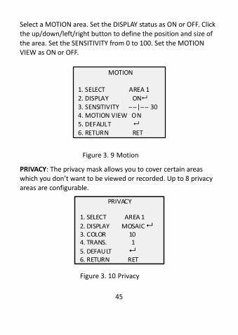
Select a MOTION area. Set the DISPLAY status as ON or OFF. Click the up/down/left/right button to define the position and size of
the area. Set the SENSITIVITY from 0 to 100. Set the MOTION VIEW as ON or OFF.
MOTION 1. SELECT AREA 12. DISPLAY ON3. SENSITIVITY ----|---- 304. MOTION VIEW ON5. DEFAULT 6. RETURN RET
Figure 3. 9 Motion
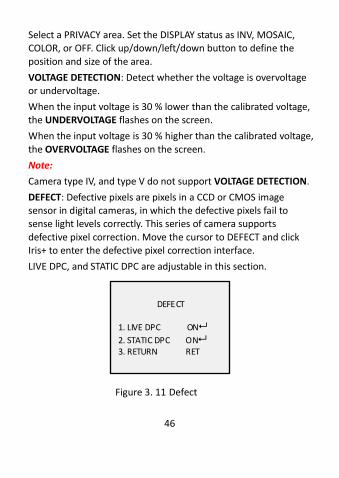
PRIVACY: The privacy mask allows you to cover certain areas which you don’t want to be viewed or recorded. Up to 8 privacy areas are configurable.
PRIVACY
1. SELECT AREA 1
2. DISPLAY MOSAIC 3. COLOR 104. TRANS. 1
5. DEFAULT 6. RETURN RET
Figure 3. 10 Privacy
46
Select a PRIVACY area. Set the DISPLAY status as INV, MOSAIC, COLOR, or OFF. Click up/down/left/down button to define the
position and size of the area.
VOLTAGE DETECTION: Detect whether the voltage is overvoltage or undervoltage.
When the input voltage is 30 % lower than the calibrated voltage, the UNDERVOLTAGE flashes on the screen.
When the input voltage is 30 % higher than the calibrated voltage,
the OVERVOLTAGE flashes on the screen.
Note:
Camera type IV, and type V do not support VOLTAGE DETECTION.
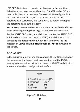
DEFECT: Defective pixels are pixels in a CCD or CMOS image sensor in digital cameras, in which the defective pixels fail to sense light levels correctly. This series of camera supports
defective pixel correction. Move the cursor to DEFECT and click Iris+ to enter the defective pixel correction interface.
LIVE DPC, and STATIC DPC are adjustable in this section.
DEFECT
1. LIVE DPC ON
2. STATIC DPC ON3. RETURN RET
Figure 3. 11 Defect
47
LIVE DPC: Detects and corrects the dynamic or the real-time defective pixels occur during the using. ON, OFF and AUTO are
selectable. The correction level from 0 to 255 is configurable if the LIVE DPC is set as ON, set it as OFF to disable the live defective pixel correction, and set it AUTO to detect and repair
the defective pixels automatically.
STATIC DPC: Detects and corrects the static or the fixed defective pixels occurring during the using. ON and OFF are selectable.
Set the STATIC DPC as ON, and click Iris+ to enter the STATIC DPC edit interface. Move the cursor to START, and click Iris+ to start
correcting the defective pixels. Click Iris + when you see the message of CLOSE THE IRIS THEN PRESS SETKEY showing up on the screen.
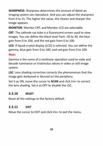
3.3.9 ADJUST
In the Adjust sub-menu, you can configure the settings, including the sharpness, the image quality on monitor, and the LSC (lens
shading compensation). Move the cursor to ADJUST and click Iris + to enter the adjust configuration interface.
ADJUST
1. SHARPNESS --------|152. MONITOR LCD
3. LSC OFF4. RETURN RET
Figure 3. 12 Adjust
48
SHARPNESS: Sharpness determines the amount of detail an imaging system can reproduce. And you can adjust the sharpness
from 0 to 15. The higher the value, the clearer and sharper the image appears.
MONITOR: Monitor CRT, and Monitor LCD are selectable.
CRT: The cathode ray tube is a fluorescent screen used to view images. You can define the black level from -30 to 30, the blue
gain from 0 to 100, and the red gain from 0 to 100.
LCD: If liquid-crystal display (LCD) is selected. You can define the gamma, blue gain from 0 to 100, and red gain from 0 to 100.
Note:
Gamma is the name of a nonlinear operation used to code and decode luminance or tristimulus values in video or still image
system.
LSC: Lens shading correction corrects the phenomenon that the image gets darkened or blurred on the periphery.
Set it as ON, move the cursor to SCAN and click Iris+ to correct the lens shading. Set it as OFF to disable the LSC.
3.3.10 RESET
Reset all the settings to the factory default.
3.3.11 EXIT
Move the cursor to EXIT and click Iris+ to exit the menu.

49