h_blasting in surface excavation (powder factor - rock type)
TRANSCRIPT
1
BLASTING IN SURFACE EXCAVATION
Any blast optimisation programme calls for a clear
understanding of the effects of principal blast parameters and
their careful application.
The degree of fragmentation of rock depends on:
a. the rock’s characteristics;
b. the properties and quantities of explosives;
c. blast geometry;
d. blast size;
e. the priming method; and
f. the initiation sequence
Terminology in bench blasting
Free face: This is an exposed rock surface towards which the
explosive charge can break out. It resembles a wall.
Face height (H): This is the vertical distance in metres
between the top and floor of the bench and should be at least
twice the burden (2B).

2
Blasthole diameter (D): Generally, the cost of drilling and
blasting decreases as hole diameter increases. The relation
between blasthole diameter and face height is approximately:
D = 0.001 to 0.02 H
Burden (B) : This is the distance in metres from a blasthole to
the nearest free face and has the following approximate
relation:
B = 25D to 40D
Or B = 25D to 30D for hard rock
B = 30D to 35D for medium rock
B = 35D to 40D for soft rock
Spacing (S) : This is the distance in metres between adjacent
blastholes and is measured perpendicular to the burden.
Usually the relation between drilled burden and spacing is:
S = 1 to 1.8B
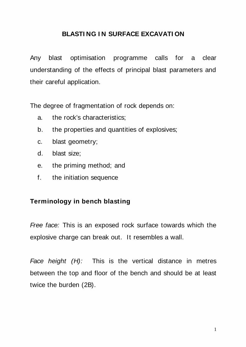
The above definition is best described by the Figure 1.
3
Figure 1: Surface blasting terminology
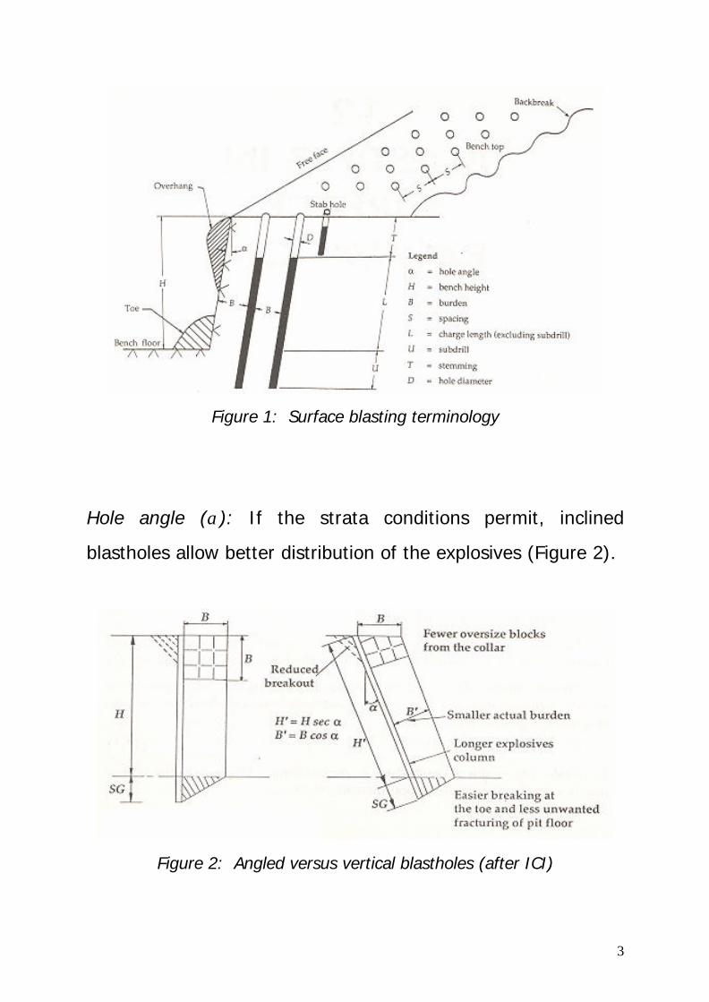
Hole angle (α): If the strata conditions permit, inclined
blastholes allow better distribution of the explosives (Figure 2).
Figure 2: Angled versus vertical blastholes (after ICI)
4
Inclined blastholes are very effective in eliminating ‘toe’ (which
is a hump of solid rock between the free face and the bench
floor), and backbreak. α varies between 00 and 300 from the
vertical plane.
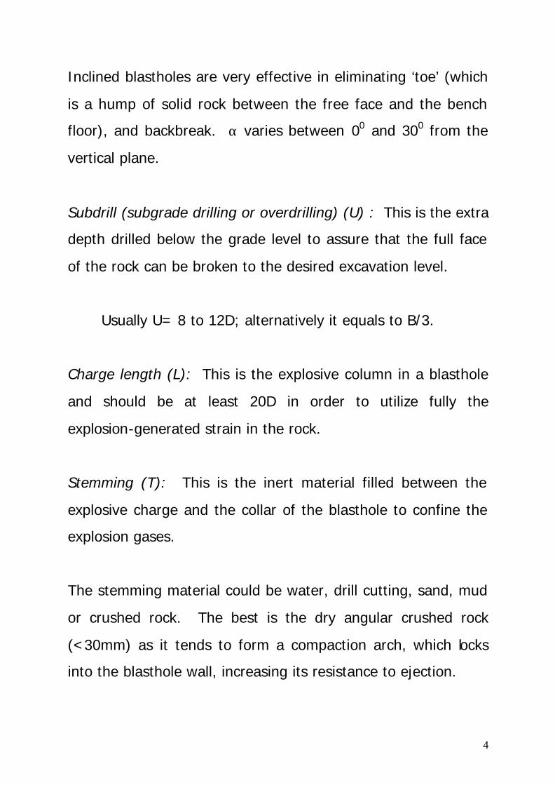
Subdrill (subgrade drilling or overdrilling) (U) : This is the extra
depth drilled below the grade level to assure that the full face
of the rock can be broken to the desired excavation level.
Usually U= 8 to 12D; alternatively it equals to B/3.
Charge length (L): This is the explosive column in a blasthole
and should be at least 20D in order to utilize fully the
explosion-generated strain in the rock.
Stemming (T): This is the inert material filled between the
explosive charge and the collar of the blasthole to confine the
explosion gases.
The stemming material could be water, drill cutting, sand, mud
or crushed rock. The best is the dry angular crushed rock
(<30mm) as it tends to form a compaction arch, which locks
into the blasthole wall, increasing its resistance to ejection.
5
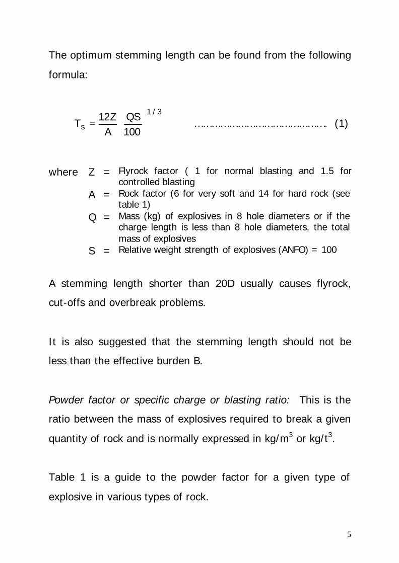
The optimum stemming length can be found from the following
formula:
3/1
s 100QS
AZ12
T
= ………………………………………. (1)
where Z = Flyrock factor ( 1 for normal blasting and 1.5 for controlled blasting
A = Rock factor (6 for very soft and 14 for hard rock (see table 1)
Q = Mass (kg) of explosives in 8 hole diameters or if the charge length is less than 8 hole diameters, the total mass of explosives
S = Relative weight strength of explosives (ANFO) = 100
A stemming length shorter than 20D usually causes flyrock,
cut-offs and overbreak problems.
It is also suggested that the stemming length should not be
less than the effective burden B.
Powder factor or specific charge or blasting ratio: This is the
ratio between the mass of explosives required to break a given
quantity of rock and is normally expressed in kg/m3 or kg/t3.
Table 1 is a guide to the powder factor for a given type of
explosive in various types of rock.
6
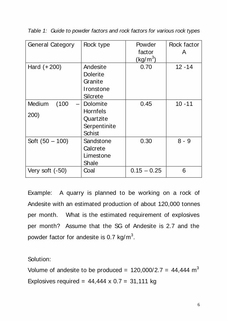
Table 1: Guide to powder factors and rock factors for various rock types General Category Rock type Powder
factor (kg/m3)
Rock factor A
Hard (+200) Andesite Dolerite Granite Ironstone Silcrete
0.70 12 -14
Medium (100 –
200)
Dolomite Hornfels Quartzite Serpentinite Schist
0.45 10 -11
Soft (50 – 100) Sandstone Calcrete Limestone Shale
0.30 8 - 9
Very soft (-50) Coal 0.15 – 0.25 6
Example: A quarry is planned to be working on a rock of
Andesite with an estimated production of about 120,000 tonnes
per month. What is the estimated requirement of explosives
per month? Assume that the SG of Andesite is 2.7 and the
powder factor for andesite is 0.7 kg/m3.
Solution:
Volume of andesite to be produced = 120,000/2.7 = 44,444 m3
Explosives required = 44,444 x 0.7 = 31,111 kg
7
Backbreak or overbreak: This is when the rockmass behind the
row of blastholes farthest from the face is broken or cracked.
Backbreak is an undesirable phenomenon because it makes he
crest of the face unsafe and often presents problems in drilling
the first row of holes for the next blast
Decoupling ratio can be defined as the ratio of the diameters of
an explosive column and the blasthole and is usually expressed
as a percentage.
For example, if an 88 mm diameter hole is charged with 64 mm
diameter cartridges,
The decoupling ratio RD = 73% 100 x 8864
=
Blasthole Patterns
1. Square versus staggered pattern
Blastholes can be drilled in either square pattern or staggered
pattern.

8
A staggered pattern produces a more uniform distribution of
explosive effect
The blastholes form equilateral triangle
Figure 3: Square versus staggered pattern. Optimum coverage is achieved in staggered pattern.
9
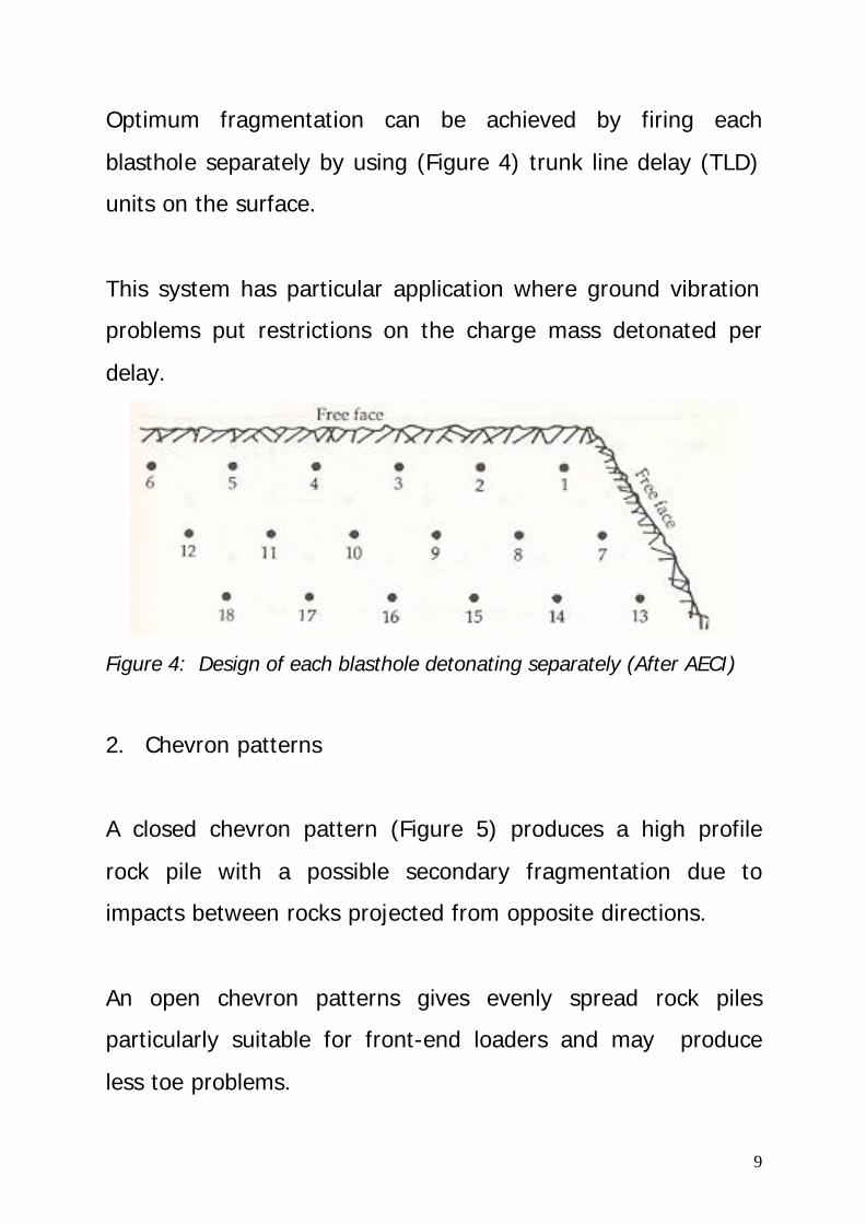
Optimum fragmentation can be achieved by firing each
blasthole separately by using (Figure 4) trunk line delay (TLD)
units on the surface.
This system has particular application where ground vibration
problems put restrictions on the charge mass detonated per
delay.
Figure 4: Design of each blasthole detonating separately (After AECI)
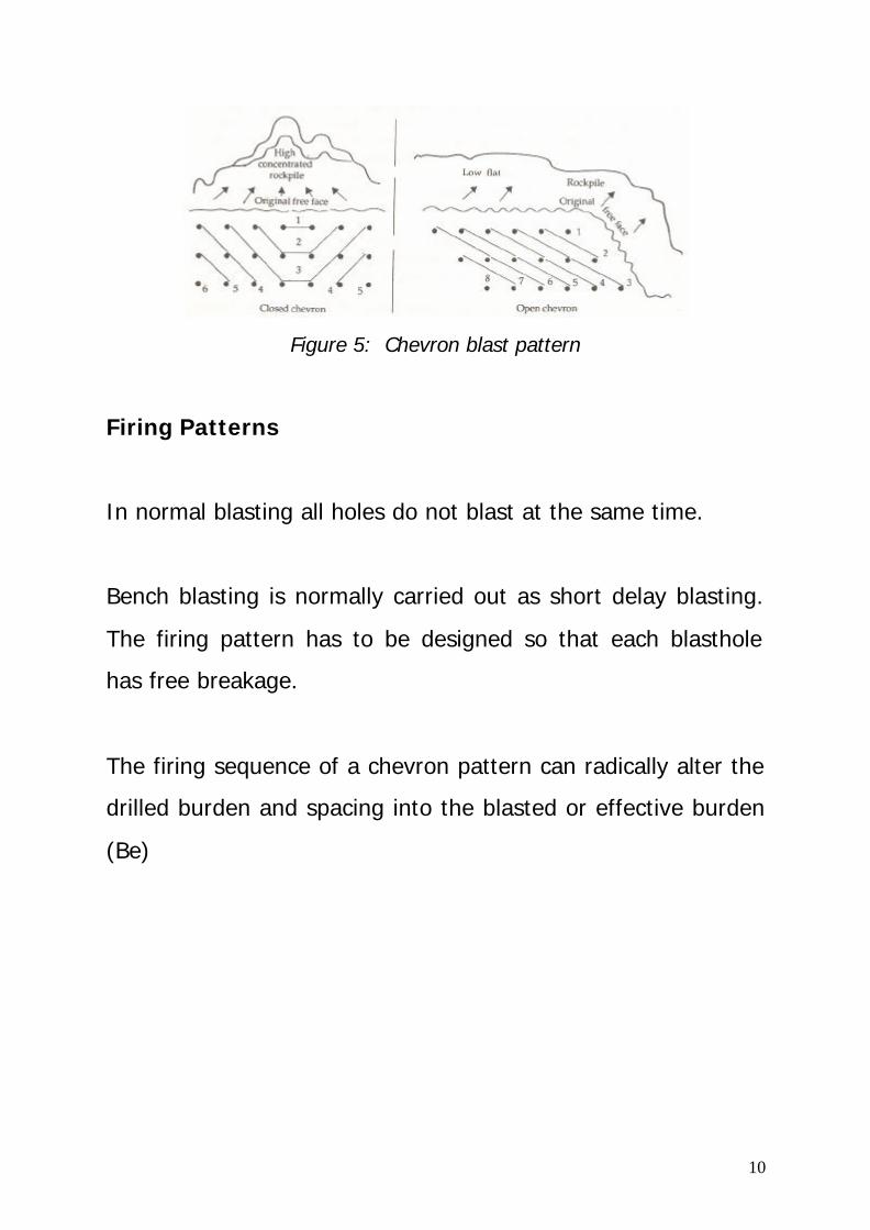
2. Chevron patterns
A closed chevron pattern (Figure 5) produces a high profile
rock pile with a possible secondary fragmentation due to
impacts between rocks projected from opposite directions.
An open chevron patterns gives evenly spread rock piles
particularly suitable for front-end loaders and may produce
less toe problems.
10
Figure 5: Chevron blast pattern
Firing Patterns
In normal blasting all holes do not blast at the same time.
Bench blasting is normally carried out as short delay blasting.
The firing pattern has to be designed so that each blasthole
has free breakage.
The firing sequence of a chevron pattern can radically alter the
drilled burden and spacing into the blasted or effective burden
(Be)
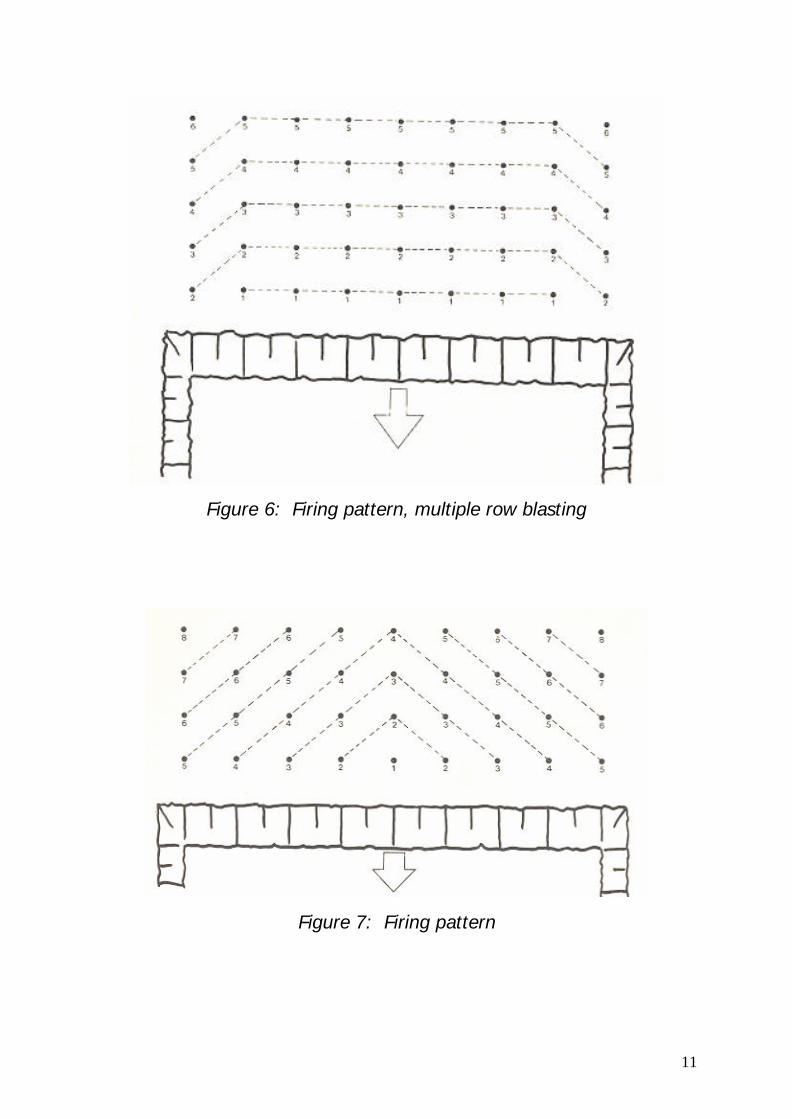
11
Figure 6: Firing pattern, multiple row blasting
Figure 7: Firing pattern

12
Figure 8: Drilled burden and spacing versus effective burden and
spacing (after ICI)
Figure 9: Hook-up system with Nonel in surface mining
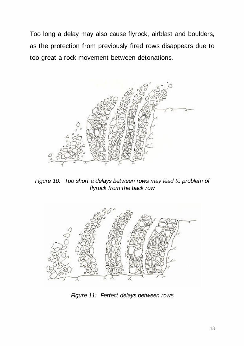
Delay Intervals
Too short a delay causes the back rows to be initiated before
the burden on the front holes has time to break away and to
move. This may cause flyrock from rows at the back.
13
Too long a delay may also cause flyrock, airblast and boulders,
as the protection from previously fired rows disappears due to
too great a rock movement between detonations.
Figure 10: Too short a delays between rows may lead to problem of
flyrock from the back row
Figure 11: Perfect delays between rows

14
Blast Size
The blasted block should be such that the length is at least
twice the width and preferably five times or more.
As the number of rows of blastholes increases, the overall rock
fragmentation improves, usually up to 5 rows. However, if the
loading equipment can handle a high profile of broken rocks
the number of rows can be increased to about 8.
Blast Design
The best use of explosives is made when a blast produces a
clean break, giving good fragmentation, while avoiding
excessive fly-rock. The success of achieving these goals
depends significantly on good blast design.
If the blastholes are drilled as a staggered pattern on an
equilateral triangular grid, the optimum distribution of the
explosive’s energy is achieved. Hence the following relation
exists:
1.15B = S
15
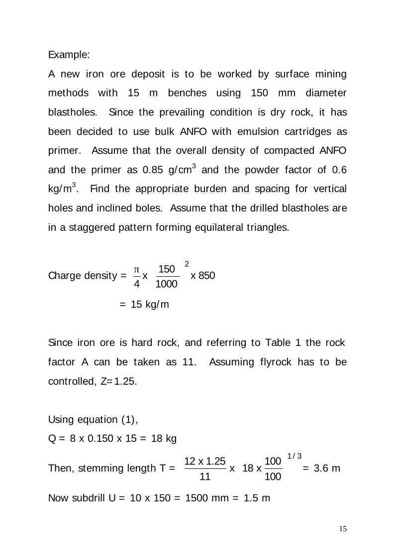
Example:
A new iron ore deposit is to be worked by surface mining
methods with 15 m benches using 150 mm diameter
blastholes. Since the prevailing condition is dry rock, it has
been decided to use bulk ANFO with emulsion cartridges as
primer. Assume that the overall density of compacted ANFO
and the primer as 0.85 g/cm3 and the powder factor of 0.6
kg/m3. Find the appropriate burden and spacing for vertical
holes and inclined boles. Assume that the drilled blastholes are
in a staggered pattern forming equilateral triangles.
Charge density = 850 x1000150
x4
2
π
= 15 kg/m
Since iron ore is hard rock, and referring to Table 1 the rock
factor A can be taken as 11. Assuming flyrock has to be
controlled, Z=1.25.
Using equation (1),
Q = 8 x 0.150 x 15 = 18 kg
Then, stemming length T = 3/1
100100
x 18 x 111.25 x 12
= 3.6 m
Now subdrill U = 10 x 150 = 1500 mm = 1.5 m
16
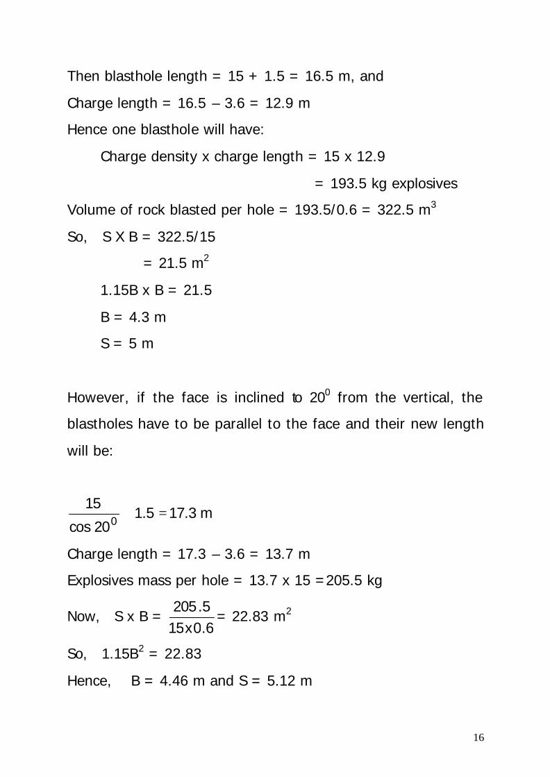
Then blasthole length = 15 + 1.5 = 16.5 m, and
Charge length = 16.5 – 3.6 = 12.9 m
Hence one blasthole will have:
Charge density x charge length = 15 x 12.9
= 193.5 kg explosives
Volume of rock blasted per hole = 193.5/0.6 = 322.5 m3
So, S X B = 322.5/15
= 21.5 m2
1.15B x B = 21.5
B = 4.3 m
S = 5 m
However, if the face is inclined to 200 from the vertical, the
blastholes have to be parallel to the face and their new length
will be:
m 17.3 1.5 20cos
150
=+
Charge length = 17.3 – 3.6 = 13.7 m
Explosives mass per hole = 13.7 x 15 =205.5 kg
Now, S x B = 6.0x155.205
= 22.83 m2
So, 1.15B2 = 22.83
Hence, B = 4.46 m and S = 5.12 m
17
Secondary Blasting
Most primary blasting, whether on surface or underground, will
leave some oversize boulders.
The term oversize boulder may be defined as any boulder
produced from primary blasting, which cannot be adequately
handled by the standard loading and crushing equipment used
in an operation. Its size varies from one operation to another,
depending on the type of loading, conveying and crushing
equipment in use.
In surface mining or quarrying, oversize boulders cause delays
in loading operations. Boulders or oversize rocks have to be
lifted out of the muckpile during digging and set aside for
secondary breakage.
In underground mines oversize may cause hang-ups in the
chutes and orepasses.
Oversize rocks may be broken by hydraulic impact breakers or
drop balls. In smaller surface mines or quarries it is not
economical to use these machines, so explosives have to be
used.
18
However, secondary blasting is the most expensive type of
blasting.
Appropriate blast design is important in order to lessen the
production of over size.
Secondary blasting can be done by pop shooting (blockholing)
and plaster shooting (mudcapping).
Shaped charges are sometime used in secondary blasting, but
this is much more expensive.
Cast Blasting
When overburden is removed from a coal or mineral deposit it
is generally cast to a waste dump by draglines, or removed by
loaders and trucks.
Cast blasting is the controlled placement of overburden into the
previously mined cut resulting in a reduced volume or
overburden material for the dragline to handle.

19
Cast blasting often results in improved fragmentation of the
overburden material, causing improved productivity for the
dragline or loader.
This type of blasting is sometimes called throw or controlled
trajectory blasting.
Figure 12: Standard blast versus throw blast profile

20