haynes 214 alloyhaynes.ch/doc/haynes/214_h3008.pdf · principal features excellent oxidation...
TRANSCRIPT

HIGH-TEMPERATURE ALLOYS
H-3008D
ContentsTypical Applications 2
Principal Features 3Oxidation Resistance 4Carburization Resistance 7
Resistance to Chlorine-BearingEnvironments 10
Nitriding Resistance 11
Physical Properties 12Modulus of Elasticity 13
Tensile Properties 14Creep and Rupture Properties 15
Thermal Stability 16Fabrication Characteristics 16
71gnidleWHealth & Safety 19
Sales Office Addresses 20
A nickel-chromium-aluminum-iron alloy with outstandingresistance to oxidation.
HAYNES® 214® ALLOY

APPLICATIONS
HAYNES® 214® alloy is gaining rapid acceptance for use in honeycomb seals because of its outstanding oxidation resistance. The seals are made of thin gage foil and are used to prevent leakage between different stages in gas turbine engines. Such seals contribute to an engines fuel efficiency.
Section of a 214 alloy belt which was removed after 3,000 hours at 1800°F (980°C) in a chinaware decorating kiln. The belt showed only minimal wear and oxidation attack. Use of 214 alloy in this application has helped reduce the time of the operation from eight or twelve hours, to less than 30 minutes.
This 214 alloy flamehood remained in service for 16 months in an application where other nickel alloy hoods required replacement every three to four months. The alloy component was subjected to direct flame impingement during the entire period in an automotive products plant.
The burner assembly at left failed after 450 cycles between minus 55 and 2000°F (minus 50 and 1095°C.) A 214 alloy burner was still in good shape after 2000 cycles in the same test. The burners were cycled from low to high temperatures in about five minutes, held for a 15-minute burn, and then rapid-air cooled.
2Haynes® 214® alloy ©2008 Haynes International, Inc.

PRINCIPAL FEATURES
excellent Oxidation ResistanceHAYNES® 214® alloy is a nickel - chromium-aluminum-iron alloy, designed to provide the optimum in high-temperature oxidation resistance for a wrought austenitic material, while at the same time allowing for conventional forming and joining. Intended principally for use at temperatures of 1750°F (955°C) and above, 214 alloy exhibits resistance to oxidation that far exceeds virtually all conventional heat-resistant wrought alloys at these temperatures. This is attributable to the formation of a tightly adherent Al2O3-type protective oxide scale, which forms in preference to chromium oxide scales at these high temperatures. At temperatures below 1750°F (955°C), 214 alloy develops an oxide scale which is a mixture of chromium and aluminum oxides. This mixed scale is somewhat less protective, but still affords 214 alloy oxidation resistance equal to the best nickel-base alloys.
The higher temperature Al2O3 - type
scale which 214 alloy forms also provides the alloy with excellent resistance to carburization, nitriding and corrosion in chlorine-bearing oxidizing environments.
FabricationHAYNES 214 alloy is similar in many respects to high aluminum content nickel-base alloys which are intended to be age-hardened by intermediate temperature heat treatment. If exposed at temperatures in the range of 1100-1700°F (595-925°C), 214 alloy will exhibit age-hardening as a result of the formation of a second phase, gamma prime (Ni3Al). This also results in a significant loss of intermediate and low temperature tensile ductility. As a consequence of this, 214 alloy is susceptible to strain-age cracking when highly-stressed, highly-restrained, welded components are slowly heated
through the intermediate temperature regime. This behavior is the same as that exhibited by high aluminum + titanium content superalloys, such as Waspaloy or R-41 alloys. The keys avoiding this problem are to minimize weldment restraint through appropriate component design, and/or heat rapidly through the 1100-1700°F (595-925°C) temperature range during post-fabrication heat treatment (or first use heat up).
With the exception of the above consideration, HAYNES 214 alloy does exhibit good forming and welding characteristics. It may be forged or otherwise hot-worked, providing it is held at 2100°F (1150°C) for a time sufficient to bring the entire piece to temperature. Its room temperature tensile ductility is also high enough to allow the alloy to be formed by coldworking. All cold or hot-worked parts should be annealed and rapidly cooled in order to restore the best balance of properties.
The alloy can be welded by a variety of techniques, including gas tungsten arc (TIG), gas metal arc (MIG) or shielded metal arc (coated electrode) welding.
Heat-TreatmentHAYNES 214 alloy is furnished in the solution heat-treated condition, unless otherwise specified. The alloy is normally solution heat-treated at 2000°F (1095°C) and rapidly cooled or quenched for optimum properties. Heat treating at temperatures below the solution heat-treating temperature will result in grain boundary carbide precipitation and, below 1750°F (955°C), precipitation of gamma prime phase. Such lower temperature agehardening heat treatments are not suggested.
available Product FormsHAYNES 214 alloy is available in the form of plate, sheet, strip, billet, bar, and wire.
applicable specificationsHAYNES 214 alloy is covered by DIN specification number 17744 No.2.4646 for all forms, and a full range of Haynes internal product specifications. Please consult Haynes International for details.
applicationsHAYNES 214 alloy combines properties which make it very suitable for service in relatively low-stress, high temperature oxidizing environments, where the utmost in resistance to oxidation or scale exfoliation is needed. Its resistance to such environments persists to temperatures as high as 2400°F (1315°C), although strength limitations may apply. Applications can include “Clean Firing” uses such as mesh belts, trays and fixtures for firing of pottery and fine china, and the heat treatment of electronic devices and technical grade ceramics.
In the gas turbine industry, 214 alloy is used for foil construction honeycomb seals, combustor splash plates, and other static oxidation - limited parts. The automotive industry has applications for 214 alloy in catalytic converter internals, and it is used as a burner cup material in auxiliary heaters for military vehicles.
In the industrial heating market, 214 alloy is used for highly specialized applications such as refractory anchors, furnace flame hoods, and rotary calciners for processing chloride compounds. It is also used for parts in high temperature chlorine-contaminated environments, such as hospital waste incinerator internals.
3 Haynes® 214® alloy
Nominal Chemical Composition, Weight Percent
ni Cr al Fe Mn si Zr C B y
75a 16 4.5 3 0.5* 0.2* 0.1* 0.05 0.01* 0.01a As Balance *Maximum

OXIDATION RESISTANCE
HAYNES 214 alloy provides resistance to oxidation at temperatures of 1750°F (955°C) and above that is virtually unmatched by any other wrought heat-resistant alloy. It can be used
for long-term continuous exposure to combustion gases or air at temperatures up to 2300°F (1260°C), and, for shorter term exposures, it can be used at even higher temperatures.
Useful short-term oxidation resistance has even been demonstrated at temperatures as high as 2400°F (1315°C).
4Haynes® 214® alloy
Comparative Oxidation Resistance in Flowing Air*
average Metal affected in 1008 Hours**
1800°F (980°C) 2000°F (1095°C) 2100°F (1150°C) 2200°F (1205°C)
Material Mils µm Mils µm Mils µm Mils µm 214® alloy 0.2 5 0.1 3 0.3 8 0.7 18
230® alloy 0.7 18 1.3 33 3.4 86 7.9 201
alloy 600 0.9 23 1.6 41 2.9 74 8.4 213
alloy 601 1.3 33 2.6 66 5.3 135 7.5*** 191***
RA330® alloy 4.3 109 6.7 170 8.7 221 - -
alloy 800H 1.8 46 7.4 188 8.9 226 13.6 289
Type 446 SS 2.3 58 14.5 368 >21.7 >551 >23.3 >592
Type 316 SS 14.3 363 >68.4 >1737 >105.0 >2667 >140.4 >3566
* Flowing air at a velocity of 7.0 feet/minute (213.4 cm/minute) past the samples. Samples cycled to room temperature once-a-week.** Metal Loss + Average Internal Penetration*** 601 Sample exhibited very large internal voids.
Metallographic Technique used for Evaluating Environmental Tests
1. Metal Loss = (A - B)/22. Average Internal Penetration = C3. Maximum Internal Penetration = D4. Average Metal Affected = ((A - B)/2) + C5. Maximum Metal Affected = (A - B)/2) + D

Comparative Oxidation in Flowing Air 2100°F (1150°C)
5 Haynes® 214® alloy
Microstructures shown are for coupons exposed for 1008 hours at 2100°F (1150°C) in air flowing at 7.0 feet/minute (213.4 cm/minute) past the samples. Samples were descaled by cathodically charging the coupons while they were immersed in a molten salt solution. The black area shown at the top of each picture represents actual metal loss due to oxidation. The data clearly show HAYNES®
214® alloy is only slightly affected by the exposure, while other nickel-chromium alloys, such as alloys 600 and 601, and ironnickel chromium alloys, such as RA330® alloy, all exhibit significantly more oxidation damage. Of particular importance is the almost total absence of internal attack for the 214 alloy. This contrasts markedly with the very substantial amount of internal attack evidenced by the alloy 601 and RA330 alloy tests coupons. The nature of this internal attack, as illustrated by the photomicrographs, is common for alloys containing 1-2% aluminum or silicon. Such levels of these elements do promote chromium oxide scale adherence, but do not afford improved resistance to oxide penetration below the scale.
Haynes® 214® alloyAverage Metal Affected
= 0.3 Mils (8 µm)
alloy 600Average Metal Affected
= 2.9 Mils (74 µm)
alloy 601Average Metal Affected
= 5.3 Mils (135 µm)
Ra330 alloyAverage Metal Affected
= 8.7 Mils (221 µm)
200 µm
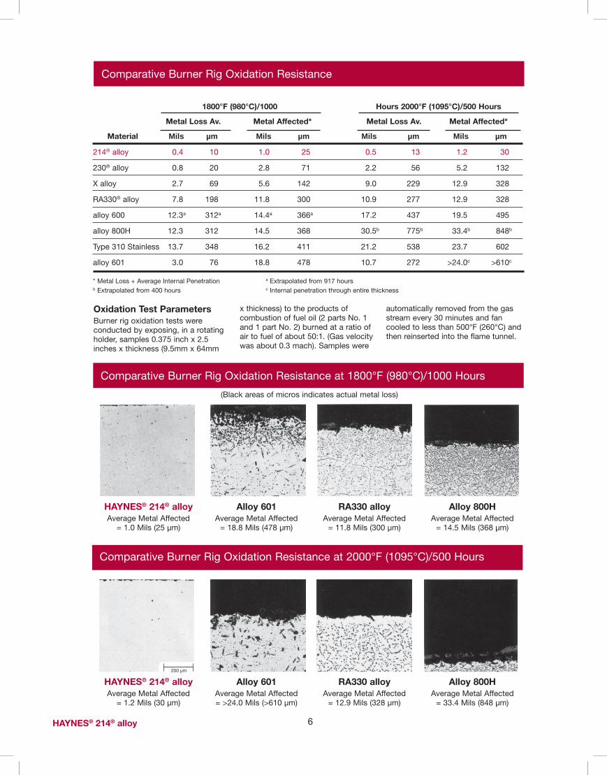
Comparative Burner Rig Oxidation Resistance
6Haynes® 214® alloy
1800°F (980°C)/1000 Hours 2000°F (1095°C)/500 Hours
Metal Loss av. Metal affected* Metal Loss av. Metal affected*
Material Mils µm Mils µm Mils µm Mils µm
214® alloy 0.4 10 1.0 25 0.5 13 1.2 30
230® alloy 0.8 20 2.8 71 2.2 56 5.2 132
X alloy 2.7 69 5.6 142 9.0 229 12.9 328
RA330® alloy 7.8 198 11.8 300 10.9 277 12.9 328
alloy 600 12.3a 312a 14.4a 366a 17.2 437 19.5 495
alloy 800H 12.3 312 14.5 368 30.5b 775b 33.4b 848b
Type 310 Stainless 13.7 348 16.2 411 21.2 538 23.7 602
alloy 601 3.0 76 18.8 478 10.7 272 >24.0c >610c
* Metal Loss + Average Internal Penetration a Extrapolated from 917 hours b Extrapolated from 400 hours c Internal penetration through entire thickness
Comparative Burner Rig Oxidation Resistance at 1800°F (980°C)/1000 Hours
(Black areas of micros indicates actual metal loss)
Oxidation Test ParametersBurner rig oxidation tests were conducted by exposing, in a rotating holder, samples 0.375 inch x 2.5 inches x thickness (9.5mm x 64mm
x thickness) to the products of combustion of fuel oil (2 parts No. 1 and 1 part No. 2) burned at a ratio of air to fuel of about 50:1. (Gas velocity was about 0.3 mach). Samples were
automatically removed from the gas stream every 30 minutes and fan cooled to less than 500°F (260°C) and then reinserted into the flame tunnel.
Haynes® 214® alloyAverage Metal Affected
= 1.0 Mils (25 µm)
alloy 601Average Metal Affected
= 18.8 Mils (478 µm)
Ra330 alloyAverage Metal Affected
= 11.8 Mils (300 µm)
alloy 800HAverage Metal Affected
= 14.5 Mils (368 µm)
alloy 601Average Metal Affected = >24.0 Mils (>610 µm)
Ra330 alloyAverage Metal Affected
= 12.9 Mils (328 µm)
alloy 800HAverage Metal Affected
= 33.4 Mils (848 µm)
Comparative Burner Rig Oxidation Resistance at 2000°F (1095°C)/500 Hours
200 µm
Haynes® 214® alloyAverage Metal Affected
= 1.2 Mils (30 µm)

HR-120® 556® 230® 214® alloy RA330® 310 253 MA®
alloy alloy alloy alloy 601 alloy alloy alloy
500 Hours @ 1800°F (980°C)in packed graphite
12
10
8
6
4
2
0
Car
bon
Ab
sorp
tion
(mg/
cm2
Packed Carburization Resistance
Mixed Gas Carburization Tests
Carbon absorption observed for 214 alloy following 500 hour exposure in packed graphite at 1800°F (980°C) was very low, as shown below.
While superior resistance was exhibited by HAYNES HR-120™ and 556™ alloys, other alloys tested exhibited significantly greater carbon
absorption. In particular, the resistance to carburization of 214 alloy was far better than that for the stainless steel type materials.
Carbon absorption observed for 214 alloy following exposure at both 1700°F (925°C) and 1800°F (980°C) to a carburizing gas mixture was significantly lower than that for all
other materials tested. This is shown in the graphs on the following pages. For these tests, the exposure was performed in a gas environment consisting of (by volume %) 5.0% H2,
5.0% CO, 5.0% CH4 and the balance argon. The calculated equilibrium composition for the test environments are shown together with the results on the following pages.
CARBURIZATION RESISTANCE
HAYNES 214 alloy has very good resistance to carburization, as measured in both packed graphite exposure tests and mixed gas exposure tests. Results for these tests are presented in the following pages.
All results are presented in terms of the mass of carbon absorption per unit area, which was obtained from the equation M = C(W/A) where M = the mass of carbon absorption per unit area (mg/cm2). C = difference in
carbon (weight fraction) before and after exposure, W = weight of the unexposed specimen (mg) and A = surface area of the specimen exposed to the test environment (cm2).
7 Haynes® 214® alloy

Comparative 1700°F (925°C) Mix Gas Carburization Tests
8Haynes® 214® alloy
HAYNES® 556® alloy
1700°F (925°C) for 215 Hours
Alloy 800H
Alloy 600
HASTELLOY® X alloy
INCONEL alloy 601
INCONEL alloy 617
HAYNES® 214® alloy
Type 310 Stainless Steel
1 2 3 4 5 6 7
Typical Carburized Microstructures (Unetched) after exposureFor 215 Hours at 1700°F (925°C)
Carbon Absorption Per Unit Area (mg/cm2)
The calculated equilibrium composition (volume %) at 1700°F (925°C) and one atma was 14.2%
H2, 4.74% CO, 0.0044% CO2, 0.032
CH4 and balance Argon. The activity of Carbon was 1.0 and the partial
pressure of Oxygen was 2.47 x 10⁻²²
atma.
HAYNES® 214® alloy Type 310 Stainless Steel
200 µm

9 Haynes® 214® alloy
Comparative 1800°F (980°C) Mixed Gas Carburization Tests
1800°F (980°C) for 55 hours
9 HAYNES 214 alloy
Typical Carburized Microstructures (Unetched) After ExposureFor 55 Hours At 1800°F (980°C)
HAYNES 214 alloy INCONEL alloy 617Note: Alloy 617 is carburized to the center of the sample.
1 3 42 5 76
INCONEL alloy 617
Alloy 600
HASTELLOY X alloy
HAYNES 556™ alloy
Alloy 800H
Carbon Absorption Per Unit Area (mg/cm2)
INCONEL alloy 601
HAYNES® 214™ alloy
Comparative 1800°F (980°C) Mixed Gas Carburization Tests
1800°F (980°C) for 55 Hours
1 2 3 4 5 6 7
HAYNES® 214® alloy INCONEL alloy 617Note: Alloy 617 is carburized to the center of the sample.
Typical Carburized Microstructures (Unetched) after exposureFor 55 Hours at 1800°F (980°C)
Carbon Absorption Per Unit Area (mg/cm2)
Alloy 800H
INCONEL alloy 617
HAYNES® 214® alloy
HAYNES® 556® alloy
Alloy 600
HASTELLOY® X alloy
INCONEL alloy 601
The calculated equilibrium composition (volume %) at 1800°F (980°C) and one atma was 14.2% H2,
4.75% CO, 0.0021% CO2, 0.024% CH4, 0.0098% H2O and balance argon. The activity of Carbon was 1.0
and the partial pressure of Oxygen was 6.78 x 10
-22 atma.
200 µm

AverageInternalPenetration
Metal Loss
RESISTANCE TO CHLORINE-BEARING ENVIRONMENTS
HAYNES 214 alloy provides outstanding resistance to corrosion in high-temperature, chlorine-contaminated oxidizing environments. This is particularly evident for
exposures at temperatures at or above 1800°F (980°C), where the formation of the Al2O3-rich protective oxide scale is favored. Test results are shown for 400 hour exposures in a flowing gas
mixture of Ar + 20% O2 + 0.25% Cl2. Note that the metal loss exhibited by 214 alloy is very low compared to other alloys tested.
10Haynes® 214® alloy
Ar-20%O2-0.25%Cl2 for 400 Hours14
12
10
8
6
4
2
350
300
250
200
150
100
50
1650°F (900°C)
214® 556®
600601
625
C-276
Ave
rage
Met
al A
ffect
ed (µ
m)
Ave
rage
Met
al A
ffect
ed (m
ils)
Ar-20%O2-0.25%Cl2 for 400 Hours
1830°F (1000°C)
C-276625
601
600
556®
Ave
rage
Met
al A
ffect
ed (µ
m)
450
400
350
300
250
200
150
100
50
18
16
14
12
10
8
6
4
2 214®
Ave
rage
Met
al A
ffect
ed (m
ils)

Resistance to Chlorine-Bearing Environments (continued)
HAYNES® 214® alloy has also been tested in environments with higher levels of chlorine contamination. The photomicrographs to the right are for samples exposed to a mixture of air and 2% chlorine for 50 hours at 1830°F (1000°C). Once again, the black area at the top of each photograph represents actual metal loss experience. Alloy 601 exhibited 2.0 Mils (51 µm) of metal loss, and an average internal penetration of 6.0 Mils (152 µm), for a total average metal affected of 8.0 Mils (203 µm). Results for 214 alloy, by contrast, were 1.0 Mils (25 µm) of metal loss, 1.0 Mils (25 µm) of average internal penetration, for a total average metal affected of only 2.0 Mils (51 µm). These results are consistent with the results for lower chlorine level, longer-term tests given on the previous page.
11 Haynes® 214® alloy
While not the most resistant alloy for nitriding environments at traditional 1000°F to 1200°F (540°C to 650°C) temperatures, 214 alloy exhibits outstanding resistance at the higher temperatures where its protective
Al2O3 scale can form, even in extremely low oxygen environments. Tests were performed in flowing ammonia at 1200, 1800 and 2000°F (650, 980 and 1095°C) for 168 hours. Nitrogen absorption was determined
by technical analysis of samples before and after exposure, and knowledge of the exposed specimen area.
NITRIDING RESISTANCE
alloy 601
Haynes® 214® alloy
nitrogen absorption (mg/cm2)
Material 1200°F (650°C) 1800°F (980°C) 2000°F (1095°C)
HAYNES® 214® alloy 1.5 0.3 0.2
Alloy 600 0.8 0.9 0.3
Alloy 601 1.1 1.2 2.6
230® alloy 0.7 1.4 1.5
Alloy 625 0.8 2.5 3.3
X alloy 1.7 3.2 3.8
Alloy 800 H 4.3 4.0 5.5
Type 310 Stainless 7.4 7.7 9.5
200 µm
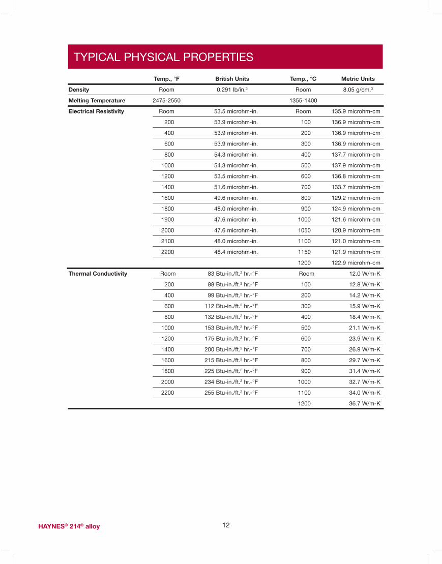
TYPICAL PHYSICAL PROPERTIES
12Haynes® 214® alloy
Temp., °F British Units Temp., °C Metric Units
Density Room 0.291 lb/in.3 Room 8.05 g/cm.3
Melting Temperature 2475-2550 1355-1400
electrical Resistivity Room 53.5 microhm-in. Room 135.9 microhm-cm
200 53.9 microhm-in. 100 136.9 microhm-cm
400 53.9 microhm-in. 200 136.9 microhm-cm
600 53.9 microhm-in. 300 136.9 microhm-cm
800 54.3 microhm-in. 400 137.7 microhm-cm
1000 54.3 microhm-in. 500 137.9 microhm-cm
1200 53.5 microhm-in. 600 136.8 microhm-cm
1400 51.6 microhm-in. 700 133.7 microhm-cm
1600 49.6 microhm-in. 800 129.2 microhm-cm
1800 48.0 microhm-in. 900 124.9 microhm-cm
1900 47.6 microhm-in. 1000 121.6 microhm-cm
2000 47.6 microhm-in. 1050 120.9 microhm-cm
2100 48.0 microhm-in. 1100 121.0 microhm-cm
2200 48.4 microhm-in. 1150 121.9 microhm-cm
1200 122.9 microhm-cm
Thermal Conductivity Room 83 Btu-in./ft.2 hr.-°F Room 12.0 W/m-K
200 88 Btu-in./ft.2 hr.-°F 100 12.8 W/m-K
400 99 Btu-in./ft.2 hr.-°F 200 14.2 W/m-K
600 112 Btu-in./ft.2 hr.-°F 300 15.9 W/m-K
800 132 Btu-in./ft.2 hr.-°F 400 18.4 W/m-K
1000 153 Btu-in./ft.2 hr.-°F 500 21.1 W/m-K
1200 175 Btu-in./ft.2 hr.-°F 600 23.9 W/m-K
1400 200 Btu-in./ft.2 hr.-°F 700 26.9 W/m-K
1600 215 Btu-in./ft.2 hr.-°F 800 29.7 W/m-K
1800 225 Btu-in./ft.2 hr.-°F 900 31.4 W/m-K
2000 234 Btu-in./ft.2 hr.-°F 1000 32.7 W/m-K
2200 255 Btu-in./ft.2 hr.-°F 1100 34.0 W/m-K
1200 36.7 W/m-K
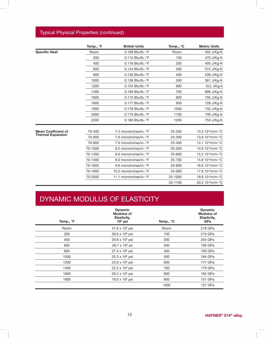
Typical Physical Properties (continued)
13 Haynes® 214® alloy
Temp., °F British Units Temp., °C Metric Units
specific Heat Room 0.108 Btu/lb.-°F Room 452 J/Kg-K
200 0.112 Btu/lb.-°F 100 470 J/Kg-K
400 0.118 Btu/lb.-°F 200 493 J/Kg-K
600 0.124 Btu/lb.-°F 300 515 J/Kg-K
800 0.130 Btu/lb.-°F 400 538 J/Kg-K
1000 0.136 Btu/lb.-°F 500 561 J/Kg-K
1200 0.154 Btu/lb.-°F 600 611 J/Kg-K 1400 0.166 Btu/lb.-°F 700 668 J/Kg-K
1600 0.173 Btu/lb.-°F 800 705 J/Kg-K
1800 0.177 Btu/lb.-°F 900 728 J/Kg-K
1900 0.178 Btu/lb.-°F 1000 742 J/Kg-K
2000 0.179 Btu/lb.-°F 1100 749 J/Kg-K
2200 0.180 Btu/lb.-°F 1200 753 J/Kg-K
Mean Coefficient of 70-400 7.4 microinches/in.-°F 25-200 13.3 10-6m/m-°CThermal expansion
70-600 7.6 microinches/in.-°F 25-300 13.6 10-6m/m-°C
70-800 7.9 microinches/in.-°F 25-400 14.1 10-6m/m-°C
70-1000 8.2 microinches/in.-°F 25-500 14.6 10-6m/m-°C
70-1200 8.6 microinches/in.-°F 25-600 15.2 10-6m/m-°C
70-1400 9.0 microinches/in.-°F 25-700 15.8 10-6m/m-°C
70-1600 9.6 microinches/in.-°F 25-800 16.6 10-6m/m-°C
70-1800 10.2 microinches/in.-°F 25-900 17.6 10-6m/m-°C
70-2000 11.1 microinches/in.-°F 25-1000 18.6 10-6m/m-°C
25-1100 20.2 10-6m/m-°C
Dynamic Dynamic Modulus of Modulus of elasticity, elasticity, Temp., °F 106 psi Temp., °C GPa
Room 31.6 x 10⁶ psi Room 218 GPa
200 30.6 x 10⁶ psi 100 210 GPa
400 29.6 x 10⁶ psi 200 204 GPa
600 28.7 x 10⁶ ps 300 199 GPa
800 27.4 x 10⁶ psi 400 190 GPa
1000 25.3 x 10⁶ psi 500 184 GPa
1200 23.9 x 10⁶ psi 600 177 GPa
1400 22.3 x 10⁶ psi 700 170 GPa
1600 20.2 x 10⁶ psi 800 162 GPa
1800 19.0 x 10⁶ psi 900 151 GPa
1000 137 GPa
DYNAMIC MODULUS OF ELASTICITY

TYPICAL TENSILE PROPERTIES
14Haynes® 214® alloy
Cold-Rolled and Solution Annealed Sheet, 0.078 to 0.125 Inches (2.0 to 3.2 mm) Thick*
Hot-Rolled and Solution Annealed Plate, 0.500 Inches (12.7 mm) Thick*
Ultimate Test Tensile yield strength elongation in Temperature strength at 0.2% Offset 2 in. (50.8 mm)
°F °C Ksi MPa Ksi MPa %
Room Room 144.2 995 87.6 605 36.8
1000 540 125.5 865 78.9 545 40.4
1200 650 118.5 815 81.1 559 25.5
1400 760 102.0 705 78.8 543 16.3
1600 870 58.2 400 45.0 310 15.4
1800 980 15.2 105 7.8 54 61.3
2000 1095 8.4 58 3.9 27 61.0
2100 1150 4.6 32 1.8 12 89.2
2200 1205 4.4 30 1.3 9 74.8
*Average of six tests for each condition
Ultimate Test Tensile yield strength elongation in Temperature strength at 0.2% Offset 1.25 (31.8 mm)
°F °C Ksi MPa Ksi MPa %
Room Room 138.9 960 82.2 565 42.8
1000 540 120.0 825 71.5 495 47.8
1200 650 114.9 790 75.9 525 33.0
1400 760 94.4 670 73.6 505 23.1
1600 870 66.4 460 50.4 345 33.6
1800 980 16.7 115 8.4 58 86.4
2000 1095 9.0 62 4.2 29 88.6
2100 1150 6.6 46 2.1 14 99.4
2200 1205 5.0 34 1.4 10 91.5
*Average of six tests for each condition
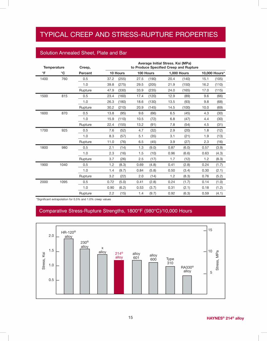
TYPICAL CREEP AND STRESS-RUPTURE PROPERTIES
average Initial stress. Ksi (MPa) Temperature Creep, to Produce specified Creep and Rupture
°F °C Percent 10 Hours 100 Hours 1,000 Hours 10,000 Hours*
1400 760 0.5 37.2 (255) 27.5 (190) 20.4 (140) 15.1 (105)
1.0 39.8 (275) 29.5 (205) 21.9 (150) 16.2 (110)
Rupture 47.9 (330) 33.9 (235) 24.0 (165) 17.0 (115)
1500 815 0.5 23.4 (160) 17.4 (120) 12.9 (89) 9.6 (66)
1.0 26.3 (180) 18.6 (130) 13.5 (93) 9.8 (68)
Rupture 30.2 (210) 20.9 (145) 14.5 (100) 10.0 (69)
1600 870 0.5 13.8 (95) 9.6 (66) 6.5 (45) 4.3 (30)
1.0 15.9 (110) 10.5 (72) 6.8 (47) 4.4 (30)
Rupture 22.4 (155) 13.2 (91) 7.8 (54) 4.5 (31)
1700 925 0.5 7.6 (52) 4.7 (32) 2.9 (20) 1.8 (12)
1.0 8.3 (57) 5.1 (35) 3.1 (21) 1.9 (13)
Rupture 11.0 (76) 6.5 (45) 3.9 (27) 2.3 (16)
1800 980 0.5 2.1 (14) 1.3 (9.0) 0.87 (6.0) 0.57 (3.9)
1.0 2.3 (16) 1.5 (10) 0.96 (6.6) 0.63 (4.3)
Rupture 3.7 (26) 2.5 (17) 1.7 (12) 1.2 (8.3)
1900 1040 0.5 1.2 (8.3) 0.69 (4.8) 0.41 (2.8) 0.24 (1.7)
1.0 1.4 (9.7) 0.84 (5.8) 0.50 (3.4) 0.30 (2.1)
Rupture 3.2 (22) 2.0 (14) 1.2 (8.3) 0.76 (5.2)
2000 1095 0.5 0.72 (5.0) 0.41 (2.8) 0.24 (1.7) 0.14 (1.0)
1.0 0.90 (6.2) 0.53 (3.7) 0.31 (2.1) 0.18 (1.2)
Rupture 2.2 (15) 1.4 (9.7) 0.92 (6.3) 0.59 (4.1)
*Significant extrapolation for 0.5% and 1.0% creep values
15 Haynes® 214® alloy
Solution Annealed Sheet, Plate and Bar
Comparative Stress-Rupture Strengths, 1800°F (980°C)/10,000 HoursS
tres
s, M
Pa
2.0
1.5
1.0
0.5
214®
alloy
RA330®
alloy
Type310
alloy600
alloy601
xalloy
230®
alloy
HR-120®
alloy
15
10
5
Str
ess,
Ksi

Condition Rockwell C Hardness
Solution Annealed 24.3
10% Cold Reduced 33.8
20% Cold Reduced 37.6
30% Cold Reduced 40.6
40% Cold Reduced 42.4
50% Cold Reduced 43.0
THERMAL STABILITY
HAYNES 214 alloy exhibits reasonable room temperature ductility after long-term thermal exposure at intermediate temperatures. Precipitation of gamma
prime phase occurs for exposures below 1750°F (955°C), along with minor chromium-rich carbides. Exposure at temperatures above
about 1700°F (925°C) have little effect upon the properties of 214 alloy, but significant grain growth can occur above about 2000°F (1095°C).
16Haynes® 214® alloy
exposure Ultimate Tensile yield strength elongation in Temperature strength at 0.2% Offset 2 in. (50.8 mm)
°F °C Hours Ksi MPa Ksi MPa %
1400 760 0 141.1 975 89.4 615 37.3
32 157.5 1085 104.6 720 27.6
100 157.8 1090 103.7 715 26.1
1000 156.4 1080 98.3 680 27.1
1600 870 0 141.1 975 89.4 615 37.3
32 139.7 965 81.6 565 35.0
100 135.5 935 76.9 530 35.1
1000 132.5 915 71.6 495 39.9
1800 980 0 141.1 975 89.4 615 37.3
32 137.5 950 84.6 585 38.0
100 137.7 950 84.7 585 34.2
1000 139.6 965 87.9 605 35.2
Room-Temperature Tensile Properties of Sheet Following Thermal Exposure
FABRICATION CHARACTERISTICS
Heat Treatment
HAYNES 214 alloy is normally final solution heat-treated at 2000°F (1095°C) for a time commensurate with section thickness. Solution heat-treating can be performed at temperatures as low as about 1950°F
(1065°C), but resulting material properties will be altered accordingly. Annealing during fabrication can be performed at even lower temperatures, but a final, subsequent solution heat treatment is needed to produce
optimum structure and properties. It is imperative that components be cooled as rapidly as possible from intermediate and final anneal operations in order to achieve maximum ductility.
Typical Hardness Properties for Sheet

Fabrication Characteristics (continued)
17 Haynes® 214® alloy
Effect of Cold Reduction upon Room-Temperature Tensile Properties*
Ultimate Percent subsequent Tensile yield strength elongation in Cold anneal strength at 0.2% Offset 2 in. (50.8 mm) Hardness
Reduction Temperature Ksi MPa Ksi MPa % Rc
0 144.7 1000 86.2 595 36.3 24.3
10 159.4 1100 121.9 840 22.5 33.8
20 176.5 1215 148.8 1025 12.9 37.6
30 194.1 1340 169.5 1170 8.1 40.6
40 208.6 1440 183.2 1265 5.3 42.4
50 219.8 1515 193.8 1335 4.0 43.0
0 - - - - - -
10 147.2 1015 90.8 625 33.1 27.4
20 150.3 1035 89.9 620 33.7 24.9
30 155.6 1075 94.2 650 33.5 27.1
40 154.3 1065 92.5 640 33.7 27.9
50 157.9 1090 95.1 655 33.7 29.3
0 - - - - - -
10 145.5 1005 83.6 575 36.2 24.3
20 149.5 1030 88.5 610 34.6 25.1
30 151.8 1045 91.8 635 33.3 24.0
40 154.1 1060 95.2 655 32.9 24.3
50 152.0 1050 90.3 625 32.3 24.4
0 - - - - - -
10 143.6 990 84.8 585 36.4 22.9
20 145.8 1005 87.2 600 34.4 24.0
30 146.2 1010 84.5 585 36.5 24.5
40 147.4 1015 86.1 595 36.5 22.5
50 148.3 1020 86.8 600 34.7 23.3
*Based upon rolling reductions taken upon 0.120-inch (3.0mm) thick sheet.Duplicate tests
1800º(982ºC)
for 5 min.
None
1900º(1038ºC)for 5 min.
2000º(1093ºC)for 5 min.
WELDING
HAYNES 214 alloy is readily welded by gas tungsten arc (GTAW), gas metal arc (GMAW), and shielded metal arc (coated electrode), welding techniques. Submerged arc welding is not recommended as this process is characterized by high heat input to the
base metal and slow cooling of the weld. These factors can increase weld restraint and promote cracking.
Base Metal Preparation The joint surface and adjacent area should be thoroughly cleaned before
welding. All grease, oil, crayon marks, sulfur compounds and other foreign matter should be removed. It is preferable that the alloy be in the solution-annealed condition when welded.

18Haynes® 214® alloy
Welding (continued)
Filler Metal SelectionMatching composition filler metal is recommended for joining 214 alloy. For shielded metal-arc welding, HASTELLOY® X electrodes (AMS 5799) are suggested. For dissimilar metal joining of 214 alloy to nickel- or cobalt-base materials,HAYNES® 230-W® filler metal will generally be a good selection, but HASTELLOY® S alloy (AMS 5838A) or HASTELLOY® W alloy (AMS 5786B, 5787A) welding products may be used. For dissimilar welding to iron-base materials, HAYNES® 556® filler metal is recommended. Please see publicationH-3159
Preheating, Interpass Temperatures and Post-Weld Heat TreatmentPreheat is not usually required so long as base metal to be welded is above 32°F (0°C). Interpass temperatures generally should be low. Auxiliary cooling methods may be used between weld passes, as needed,
providing that such methods do not introduce contaminants. Post weld-heat treatment for 214 alloy depends on part thickness and complexity. For 214 alloy fabrications that will be in service at 1200-1800ºF, weldments made of greater than 1/4" thickness, or those which have been welded into configurations which create significant residual stresses, a post weld annealing heat treatment is suggested. The objective of a post weld heat treatment is to minimize and eliminate residual stress in the assembly.
A heat treatment at a metal temperature between 1900ºF and 2000ºF has been successful. The metal at temperature as little as 5 minutes is usually sufficient. If no additional welding or forming is to be performed, the fabrication may be air cooled, otherwise rapid cooling is advised.
Care must be taken when annealing. Heating 214 alloy through the temperature range of 1200-1800ºF
will cause gamma prime (Ni3Al) to precipitate. This gamma prime precipitation results in a net shrinkage, as well as an increase in strength and corresponding loss of ductility. In weldments and other highly stressed components, strain-age cracking may occur. This occurs when the residual stresses from forming and welding, augmented by stresses caused by precipitation, exceed the rupture strength of the base metal. It is important to heat the material through the 1200-1800ºF temperature range as rapidly as possible. Do not stress relieve in the 1200-1800ºF temperature range.
Nominal Welding ParametersNominal welding parameters are provided as a guide for performing typical operations. These are based upon welding conditions used in Haynes International, Inc. laboratories. For further information, please consult Haynes International.
Automatic Gas Tungsten Arc Welding
square Butt Joint - no Filler Metal added
Material Thickness 0.040" (1.0mm) 0.062" (1.6mm) 0.125" (3.2mm)Current (DCEN), amperes 50 80 120Voltage 8 8.5 9.5Travel Speed, in/min. (mm/min) 10 (254) 12 (305) 12(305)Electrode Size, in (mm) 1/16 (1.6) 3/32 (2.4) 1/8 (3.2)Electrode Shape 45º inc 45º inc 45º incCup Size #8 #8 #8Shielding Gas Flow, CFH (l/min.) 30 (14.2) 30 (14.2) 30 (14.2)Gas Type Argon Argon ArgonBacking Gas, CFH (l/min.) 10 (4.7) 10 (4.7) 10 (4.7)Gas Type Argon Argon Argon
Manual Gas Tungsten Arc Welding
V-or U-Groove - all Thicknesses 1/8" (3.2) mm) or greater
Technique - Stringer Bead Current (DCEN), amperes - 120 root, 140-150 Fill Voltage - 11 to 14 Filler Metal - 1/8" diameter (3.2 mm) 214 alloy Travel Speed, ipm (mm/min) - 4 to 6 (102-152) Electrode Size, in (mm) - 1/8" diameter (3.2 mm) Electrode Shape - 30º included Cup Size - #8 or larger Gas Type - Argon Shielding Gas Flow, CFH (l/min.) - 30 to 35 (14.2 to 16.5) Backing Gas Flow, CFH (l/min.) - 10 (4.7) or back -gouge to sound metal and fill from root side Preheat - Ambient Interpass Temperature Maximum - 200ºF (93ºC)

Gas Metal Arc Welding
19 Haynes® 214® alloy
HEALTH AND SAFETY
Welding can be a safe occupation. Those in the welding industry, however, should be aware of the potential hazards associated with welding fumes, gases, radiation, electric shock, heat, eye injuries, burns, etc. Also, local, municipal, state, and federal regulations (such as those issued by OSHA) relative to welding and cutting processes should be considered.
Nickel-, cobalt-, and iron-base alloy products may contain, in varying concentration, the following elemental constituents: aluminum, cobalt, chromium, copper, iron, manganese, molybdenum, nickel and tungsten. For
specific concentrations of these and other elements present, refer to the Material Safety Data Sheets (MSDS) available from Haynes International, Inc.
Inhalation of metal dust or fumes generated from welding, cutting, grinding, melting, or gross handling of these alloys may cause adverse health effects such as reduced lung function, nasal and mucous membrane irritation. Exposure to dust or fumes which may be generated in working with these alloys may also cause eye irritation, skin rash and effects on other organ systems.
The operation and maintenance of welding and cutting equipment should conform to the provision of American National Standard ANSI/AWS Z49.1, "Safety in Welding and Cutting". Attention is especially called to Section 4 (Protection of Personnel) and 5 (Health Protection and Ventilation) of ANSI/AWS Z49.1. Mechanical ventilation is advisable and, under certain conditions such as a very confined space, is necessary during welding or cutting operations, or both, to prevent possible exposure to hazardous fumes, gases, or dust that may occur.
No matching chemistry SMAW electrodes are currently available for 214 alloy.
HASTELLOY X electrodes (AMS 5799) have been successfully used to join 214 alloy.
Typical parameters for X alloy electrodes (flat position) are given below.
acknowledgements:INCONEL is a registered trademark of Inco Family of Companies.RA330 is a registered trademarks of Rolled Alloys, Inc.253 MA is a registered trademark of Avesta Jernverks Aktiebolag.HELISTAR® SS is a registered trademark for Praxair.
short Circuiting Transfer Mode spray Transfer Mode all Thicknesses 0.090" (2.3 mm) all Thicknesses 0.156" (4.0mm) and greater and greater
Wire Type 214® alloy 214 alloy
Wire Diameter, in (mm) 0.045 (1.1) 0.062 (1.6)
Feed Speed, ipm (m/min) 170 to 190 (4.3 to 4.8) 160 to 170 (4.0 to 4.3)
Current (DCEP), amperes 100 to 110 210 to 230
Voltage 20 to 22 28 to 30
Stickout, in (mm) 1/2-3/4 (12.7 to 19.1) 3/4 (19.1)
Travel Speed, ipm (mm/min) 8 to 10 (203 to 254) 9 to 12 (229 to 305)
Torch Gas Flow, CFH (l.min.) 40 (18.9) 40 (18.9)
Gas Type HELISTAR® SS (66.1% Ar, 33% He, Argon
0.9% CO2) or 75% Ar + 25% He
electrode Diameter Voltage Current (DCeP) Travel speed
in (mm) amperes ipm (mm/mm)
3/32 (2.4) 22 - 24 45 - 75 3 - 5 (76 - 127)
1/8 (3.2) 22 - 24 70 - 110 4 - 6 (102 - 152)
5/32 (4.0) 23 - 25 110 - 140 4 - 6 (102 - 152)
Shielded Metal Arc Welding

STANDARD PRODUCTSBy Brand or Alloy Designation:
HasTeLLOy® Family of Corrosion-Resistant alloys
B-3®, C-4, C-22®, C-276, C-2000®, C-22HS®, G-30®, G-35®, G-50®, HYBRID-BC1™, and N
HasTeLLOy® Family of Heat-Resistant alloys
S, W, and X
Haynes® Family of Heat-Resistant alloys
25, R-41, 75, HR-120®, HR-160®, 188, 214®, 230®, 230-W®, 242®, 263, 282®, 556®, 617, 625, 65SQ®, 718, X-750, MULTIMET® ,NS-163™, and Waspaloy
Corrosion-Wear Resistant alloy Wear-Resistant alloy
ULTIMET® 6B
Haynes® Titanium alloy Tubular
Ti-3Al-2.5V
standard Forms: Bar, Billet, Plate, Sheet, Strip, Coils, Seamless or Welded Pipe & Tubing, Pipe Fittings, Flanges, Fittings, Welding Wire and Coated Electrodes
Properties Data: The data and information in this publication are based on work conducted principally by Haynes International, Inc. and occasionally supplemented by information from the open literature, and are believed to be reliable. However, we do not make any warranty or assume any legal liability or responsibility for its accuracy, completeness or usefulness, nor does Haynes represent that its use would not infringe upon private rights.
Any suggestions as to uses and applications for specific alloys are opinions only and Haynes International, Inc. makes no warranty of results to be obtained in any particular situation. For specific concentrations of elements present in a particular product and a discussion of the potential health effects thereof, refer to the Material Safety Data Sheet supplied by Haynes International, Inc. All trademarks are owned by Haynes International, Inc.
Global Headquarters1020 West Park Avenue
P.O. Box 9013Kokomo, Indiana 46904-9013 (USA)
Phone: 1-800-354-0806 or (765) 456-6012Fax: (765) 456-6905
www.haynesintl.comFor your local sales office or service center, please call or visit our website.020108