harrington engineering & construction, llc · harrington engineering & construction, llc...
TRANSCRIPT
TM
HEC&Harrington Engineering & Construction, LLC
Technical Memorandum Waukegan Harbor – Slip 3 Field Sampling Results
TTEECCHHNNIICCAALL MMEEMMOORRAANNDDUUMM Date: June 22, 2007 To: John Moore, P.E., City of Waukegan From: Robert Solak, P.E. cc: T. Harrington, Harrington Engineering & Construction G. Deigan, Deigan & Associates RE: Waukegan Harbor Slip 3 – Field Sampling Results This memorandum presents the data collected from the field sampling conducted at the OMC Superfund Site in Waukegan, Illinois. The sampling was conducted in support of the Slip 3 Containment Alteration design, to be prepared by Harrington Engineering and Construction, LLC (HEC). The objectives of the investigative sampling were:
1. To provide data on the extent of PCB’s in the overlaying surcharge sand, 2. To determine if surcharge sand can be visually distinguished from underlying
sediment, and 3. To provide geotechnical information for design of foundations for a dry-rack
storage building to be located on the Slip No. 3 Containment Cell. The investigative sampling found that the surcharge sand is visually distinguishable from the underlying sediment. However, the PCBs sample results indicate that separation of the different materials may not be necessary during the alteration work. Analysis of the geotechnical data gathered has shown that a piling foundation, instead of conventionally spread footings, will be required for the proposed boat storage facility. Background The Slip No. 3 Containment Cell was created and filled with PCB-containing sediments in 1991 and 1992. Two rows of sheet pile were installed across the mouth of Slip No. 3, with the space between filled with a sand-bentonite mix, to isolate the cell from Lake Michigan. An impermeable soil-bentonite cut off wall was installed 20-40 feet behind the existing Slip No. 3 sheet pile walls and tied into the sand-bentonite mix in the double sheet pile wall along the mouth to isolate the cell from local groundwater. The former slip area was then filled with dredged sediments to an elevation of approximately 3 feet below natural grade. Sand was placed over the dredged sediments to surcharge load the sediment, accelerating the settlement of the sediments. After two years of settling, the surcharge sand was graded for drainage (2% slope on the top of the cap) and a 60-mil high-density polyethylene (HDPE) liner was placed over the surcharge sand. The HDPE liner was
Technical Memorandum 2 Waukegan Harbor – Slip 3 Field Sampling Results
overlaid with a geogrid drain layer, geotextile filter fabric, 18 inches of sand, and 6 inches of topsoil. A dewatering system was also installed to maintain groundwater elevation inside the Slip No. 3 Containment Cell lower than the surrounding groundwater. The final elevation of the containment cell cover was approximately 5 feet above the surrounding land, at its highest point. The City seeks to return the land area above the Slip No. 3 Containment Cell to beneficial use by the neighboring marina (Larsen Marine Services) for indoor/outdoor boat storage. To effect this usage, removal of portions of the surcharge sand, beneath the liner, will be required, as well as the construction of building foundations. The details of this alteration are to be provided in design drawings, currently in preparation. A Field Sampling Plan (FSP), dated May 2006, was prepared by HEC to aid in design of the alteration of the containment cell. The plan called for eight (8) borings to be advanced, recovered, and sampled for PCBs at various depth intervals using direct-push methods. A maximum of 40 environmental samples (5 per boring) were anticipated. The borings were to be advanced to a depth of approximately 10 feet below the HDPE liner. The plan also called for two (2) borings to be advanced for the collection of geotechnical data using hollow stem auger and split spoon methods. These borings were to proceed to the Chicago hardpan (approximately 25-35 feet below ground surface). Schedule The field sampling was conducted on March 6 and 7, 2007. Repair of the liner at the boring locations was completed May 14 through 16, 2007. Personnel The following personnel were involved in the field sampling effort. Name Affiliation Purpose Bob Solak HEC Project Engineer / Task Manager Gary Deigan Deigan & Associates, LLC Project Manager / Coordinator for
City of Waukegan Kerry Van Allen Deigan & Associates, LLC Project Geologist John Noyes, P.G. Cabeno Environmental Cone Penetrometer Operator Drill Crew (2) Cabeno Environmental Geoprobe™ Operators Liner Repair Crew (3)
Independent Environmental Services
Liner repair
Field Sampling Methods Two changes to the FSP were initiated prior to the field sampling effort. First, due to frozen soil conditions, it was decided not to excavate down to the liner and cut it by hand prior to advancing the soil borings. Rather, the Geoprobe™ was advanced through the cover soils and the HDPE liner to obtain samples of underlying soil and sediment. Second, rather than collect geotechnical data using hollow-stem auger and split spoon, it was decided to use cone penetrometer soundings to collect some of the desired data.

Technical Memorandum 3 Waukegan Harbor – Slip 3 Field Sampling Results
Environmental Sampling Eight borings for environmental sample collection were advanced using a 6610DT tracked Geoprobe™ rig, equipped with a 3-inch diameter split spoon sampler using disposable acetate sleeves. Soil cores were continuously collected and logged by the Project Geologist. The borings were designated SB-101 through SB-108. Boring locations are shown on Figure 1. Boring logs are presented in Attachment A. Between four and five soil samples were collected from each boring, depending upon the total depth of the boring and the amount of recovery from each split spoon interval. Soil from the designated sample interval was well mixed in a stainless steel bowl and 4 oz. of the mixed soil were placed into laboratory-supplied glass jars. A total of thirty-six (36) samples were submitted for PCB and percent moisture analysis. The samples were cooled to 4 deg. C and submitted for analysis by Severn Trent Laboratories, Inc. (STL) of University Park, Illinois. Analytical reports are provided in Attachment D. The stainless steel drive points on the split spoon as well as the mixing bowl and utensils were decontaminated between the collection of each sample as specified in the FSP. Sampling personnel donned disposable gloves prior to the collection of each sample. All boreholes were filled with bentonite pellets to prevent vertical migration of precipitation into the containment cell, until the HDPE cover repair was completed in May 2007 (see Liner Repair description, below). Geotechnical Sampling Three soundings, to collect geotechnical data, were advanced using a 6610DT tracked Geoprobe™ rig, equipped with cone penetrometer (CPT) sounding equipment. The CPT test methods employed conformed to ASTM D 5778-97, “Standard Test Method for Performing Electronic Friction and Piezocone Testing of Soils”. The CPT consisted of a steel cone on the end of a series of rods that were pushed into the ground at a constant rate of 2 centimeters per second, while continuous measurements were made electronically. Data was translated into tip to sleeve ratios and blow counts. The CPT also provided real-time output of soil lithology information. CPT soundings are provided in Attachment B. Split-spoon, direct-push borings were also advanced within 5 feet of the CPT location in order to collect soil samples for geotechnical testing. Two intervals of soil were sampled from each CPT location and analyzed by STL for particle size (by ASTM D422) and percent solids. Results are provided in Attachment D. Six samples each were collected from borings GB-01 and GB-02 and two samples were collected from GB-03 and analyzed by STL for moisture content. Results are provided on Table 1. Boring logs for the three geotechnical borings are provided in Attachment A. One sounding (designated on Figure 1 as GB-03A) was refused at a depth of approximately 7.5 feet below ground surface and abandoned (data not collected). The sounding was relocated (designated as GB-03B on Figure 1) and refused again. A corresponding split spoon, however, was successfully advanced at the GB-03B location.

Technical Memorandum 4 Waukegan Harbor – Slip 3 Field Sampling Results
All analytical results identified as GB-03 refer to location GB-03B. All boreholes were filled with bentonite pellets to prevent vertical migration of precipitation into the containment cell until the HDPE cover could be repaired. Data Validation Laboratory precision was evaluated by calculating the relative percent difference for sample duplicates. The table below presents those calculations
Sample ID Parameter Units Duplicate Sample RPD (%) SB-101, 10-12' PCB-1248 ug/kg 3300 3700 11.4% % Moisture % 7.1 5.4 27.2% SB-102, 7-8.2' PCB-1248 ug/kg 5500 9700 55.3% % Moisture % 13 9.4 32.1% SB-104, 2.5-4' PCB-1248 ug/kg 1400 2000 35.3% % Moisture % 4.1 4 2.5% SB-106, 5-7' PCB-1248 ug/kg 420 470 11.2% % Moisture % 5.1 3.6 34.5%
The relative percent differences between the duplicates and the samples indicated minor precision issues. It is unknown if the differences are related to laboratory methods/equipment, sample matrix heterogeneity, or incomplete mixing of the sample interval prior to sample and duplicate collection. Given that the data was primarily being used to determine vertical and spatial variability in the containment cell, the precision of the data set is believed to be adequate. No PCBs were detected above the reporting limit in any of the field or method blanks. All samples were analyzed within the method-required holding times. Analytical accuracy was evaluated by reviewing surrogate spikes and laboratory blanks. All surrogate and laboratory control spike recoveries were within the acceptable ranges. Liner Repair Following the sampling event and the thaw of the site cover soil, a liner repair crew was mobilized to the site. The crew excavated each boring location down to the geocomposite drainage layer, cut it away, and exposed the penetration of the HDPE cover layer. A patch of HDPE material was cut to size and the existing liner was cleaned and lightly abraded in the areas to receive the patch. The patch and the cover area were heated to adhere the patch to the cover, and then the patch was extrusion welded to the cover. Once cooled, the patch welds were vac-boxed tested for leaks and, if none were found, the geocomposite drain layer was zip-tied back into place over the patch. The excavation was then backfilled. One patch failed vac-box testing, was repaired, and re-tested successfully. A total of 12 locations (eight soil borings, three geotechnical borings, and one refused boring) were repaired. The CPT locations required repairs of 5 punctures each (The CPT puncture, the corresponding split spoon puncture, and three helical anchor punctures required for the CPT).

Technical Memorandum 5 Waukegan Harbor – Slip 3 Field Sampling Results
Investigative-derived wastes All waste derived from the sampling activities, including PPE, soil material, acetate sleeves, decontamination fluids, etc., were placed into two 55-gallon drums and labeled with “non-hazardous” waste and “PCB-containing” stickers, in accordance with the FSP. The drums were moved by and stored under the custody of the City of Waukegan in a locked storage area at the former OMC building. Photographs of the drums are included in Attachment C. Sampling Results and Conclusions PCB soil sample results are presented in Table 1 and Figure 1. The STL analytical reports are included in Attachment D. Reported concentrations from all samples ranged from 250 to 45,000 ug/kg total PCB. Samples collected from boring intervals above 581.0’ mean sea level (the lowest expected excavation depth during cell alteration) ranged from 470 to 26,000 ug/kg. In general, reported PCB concentrations were lower in samples from the presumed surcharge material than in the underlying sediment, however this was not always the case (refer to results for SB-101 and SB-106). Since all samples were below the 50 mg/kg level, however, the need to differentiate between these two material types during the Slip 3 alteration will not be critical. No horizontal trends in PCB concentrations could be inferred from the data. Soil lithology observations, as noted on the boring logs in Attachment A, indicated a visible difference between the sediment and the surcharge sand in the containment cell. The surcharge sand was described as a brown/gray fine sand. Black-colored fine sand, silt, and clay generally marked the transition to the sediment layer. The surcharge layer was found to be typically between 2 and 4 feet thick, however, there were some exceptions of apparently thicker layers (SB-103, -107, and –108 and GB-03) and one thinner (GB-02). In summary, PCB concentrations in both the sediment and surcharge layers were below 50 mg/kg at the locations sampled. A visible difference between the surcharge sand and the sediment was noted, and thus, separation of the layers during excavation would be feasible. However, due to the relatively low PCB concentrations, the need to separately handle these two layers may not be critical during alteration of the containment cell. Additionally, geotechnical data gathered during the field sampling effort have indicated that a piling foundation system is appropriate for the planned building construction at this site.

Technical Memorandum 6 Waukegan Harbor – Slip 3 Field Sampling Results
Table 1 Sampling Summary Figure 1 PCB Sampling Results Attachment A Soil Boring Logs Attachment B Cone Penetrometer Soundings Attachment C Photographic Log Attachment D STL Analytical Reports
RAS/ras/gd
\\2000SERVER\Projects\06-001 Waukegan Harbor - Harrington\Field Sampling\TM Field Sampling Results.doc
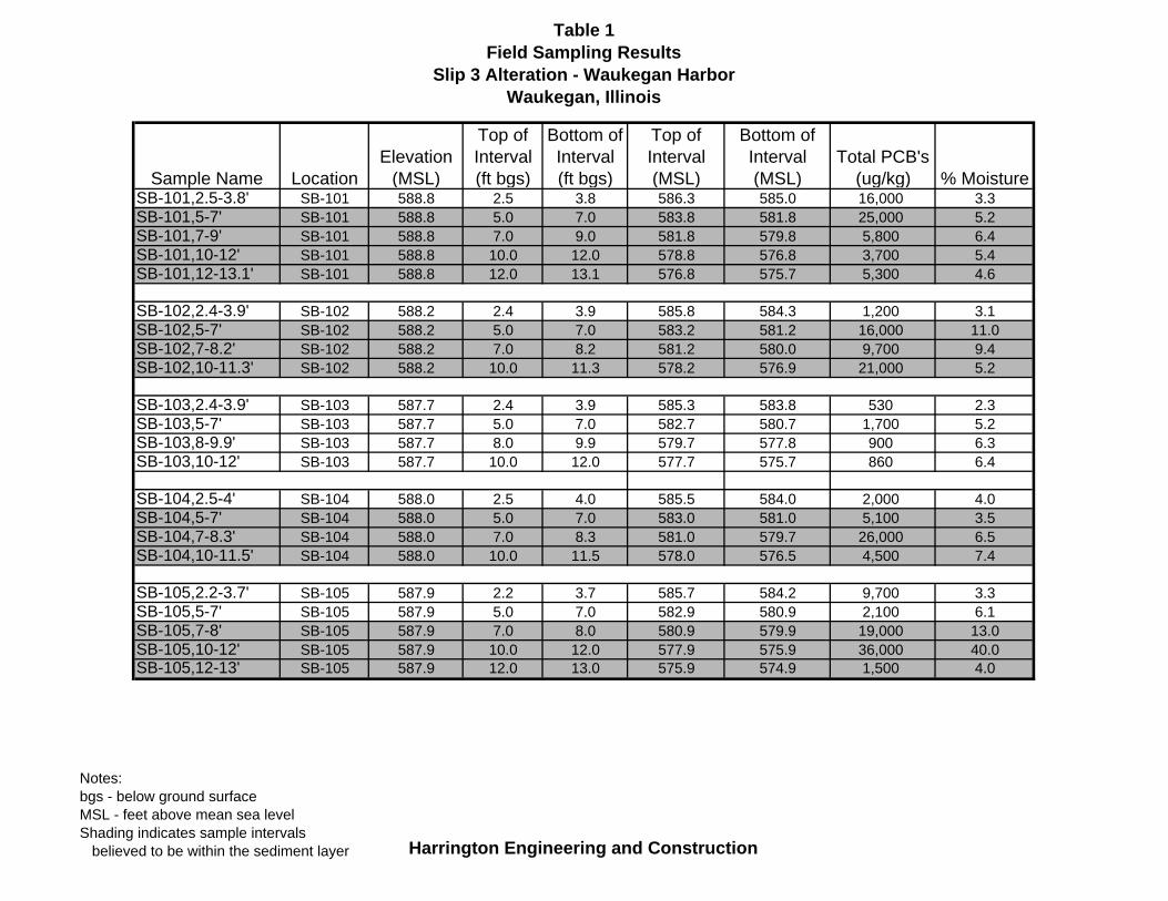
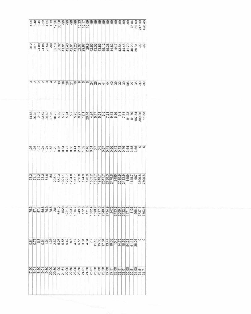
Table 1Field Sampling Results
Slip 3 Alteration - Waukegan HarborWaukegan, Illinois
Sample Name LocationElevation
(MSL)
Top of Interval (ft bgs)
Bottom of Interval (ft bgs)
Top of Interval (MSL)
Bottom of Interval (MSL)
Total PCB's (ug/kg) % Moisture
SB-101,2.5-3.8' SB-101 588.8 2.5 3.8 586.3 585.0 16,000 3.3SB-101,5-7' SB-101 588.8 5.0 7.0 583.8 581.8 25,000 5.2SB-101,7-9' SB-101 588.8 7.0 9.0 581.8 579.8 5,800 6.4SB-101,10-12' SB-101 588.8 10.0 12.0 578.8 576.8 3,700 5.4SB-101,12-13.1' SB-101 588.8 12.0 13.1 576.8 575.7 5,300 4.6
SB-102,2.4-3.9' SB-102 588.2 2.4 3.9 585.8 584.3 1,200 3.1SB-102,5-7' SB-102 588.2 5.0 7.0 583.2 581.2 16,000 11.0SB-102,7-8.2' SB-102 588.2 7.0 8.2 581.2 580.0 9,700 9.4SB-102,10-11.3' SB-102 588.2 10.0 11.3 578.2 576.9 21,000 5.2
SB-103,2.4-3.9' SB-103 587.7 2.4 3.9 585.3 583.8 530 2.3SB-103,5-7' SB-103 587.7 5.0 7.0 582.7 580.7 1,700 5.2SB-103,8-9.9' SB-103 587.7 8.0 9.9 579.7 577.8 900 6.3SB-103,10-12' SB-103 587.7 10.0 12.0 577.7 575.7 860 6.4
SB-104,2.5-4' SB-104 588.0 2.5 4.0 585.5 584.0 2,000 4.0SB-104,5-7' SB-104 588.0 5.0 7.0 583.0 581.0 5,100 3.5SB-104,7-8.3' SB-104 588.0 7.0 8.3 581.0 579.7 26,000 6.5SB-104,10-11.5' SB-104 588.0 10.0 11.5 578.0 576.5 4,500 7.4
SB-105,2.2-3.7' SB-105 587.9 2.2 3.7 585.7 584.2 9,700 3.3SB-105,5-7' SB-105 587.9 5.0 7.0 582.9 580.9 2,100 6.1SB-105,7-8' SB-105 587.9 7.0 8.0 580.9 579.9 19,000 13.0SB-105,10-12' SB-105 587.9 10.0 12.0 577.9 575.9 36,000 40.0SB-105,12-13' SB-105 587.9 12.0 13.0 575.9 574.9 1,500 4.0
Notes:bgs - below ground surfaceMSL - feet above mean sea levelShading indicates sample intervals believed to be within the sediment layer Harrington Engineering and Construction

Table 1Field Sampling Results
Slip 3 Alteration - Waukegan HarborWaukegan, Illinois
Sample Name LocationElevation
(MSL)
Top of Interval (ft bgs)
Bottom of Interval (ft bgs)
Top of Interval (MSL)
Bottom of Interval (MSL)
Total PCB's (ug/kg) % Moisture
SB-106,2.5-4.0' SB-106 586.8 2.5 4.0 584.3 582.8 510 3.2SB-106,5-7' SB-106 586.8 5.0 7.0 581.8 579.8 470 3.6SB-106,7-8.4' SB-106 586.8 7.0 8.4 579.8 578.4 310 4.8SB-106,10-12' SB-106 586.8 10.0 12.0 576.8 574.8 250 6.7SB-106,12-14' SB-106 586.8 12.0 14.0 574.8 572.8 1,000 5.7
SB-107,2.5-4' SB-107 588.2 2.5 4.0 585.7 584.2 5,200 5.9SB-107,5-7' SB-107 588.2 5.0 7.0 583.2 581.2 4,200 9.3SB-107,7-9' SB-107 588.2 7.0 9.0 581.2 579.2 5,800 16.0SB-107,10-11.6' SB-107 588.2 10.0 11.6 578.2 576.6 3,200 7.8SB-107,11.6-13.5' SB-107 588.2 11.6 13.5 576.6 574.7 42,000 25.0
SB-108,2.5-4.3' SB-108 587.1 2.5 4.3 584.6 582.8 7,100 5.2SB-108,5-7' SB-108 587.1 5.0 7.0 582.1 580.1 590 6.0SB-108,7-8.5' SB-108 587.1 7.0 8.5 580.1 578.6 290 3.7SB-108,10-12.3' SB-108 587.1 10.0 12.3 577.1 574.8 1,200 4.3
GB-01,3' GB-01 588.3 3 - 585.3 - - 3.1GB-01,7' GB-01 588.3 7 - 581.3 - - 41GB-01,11' GB-01 588.3 11 - 577.3 - - 5.6GB-01,15' GB-01 588.3 15 - 573.3 - - 44GB-01,19' GB-01 588.3 19 - 569.3 - - 16GB-01,23' GB-01 588.3 23 - 565.3 - - 16
Notes:bgs - below ground surfaceMSL - feet above mean sea levelShading indicates sample intervals believed to be within the sediment layer Harrington Engineering and Construction

Table 1Field Sampling Results
Slip 3 Alteration - Waukegan HarborWaukegan, Illinois
Sample Name LocationElevation
(MSL)
Top of Interval (ft bgs)
Bottom of Interval (ft bgs)
Top of Interval (MSL)
Bottom of Interval (MSL)
Total PCB's (ug/kg) % Moisture
GB-02,3' GB-02 587.9 3 - 584.9 - - 5.3GB-02,6' GB-02 587.9 6 - 581.9 - - 4.7GB-02,11' GB-02 587.9 11 - 576.9 - - 7.2GB-02,16' GB-02 587.9 16 - 571.9 - - 29GB-02,20' GB-02 587.9 20 - 567.9 - - 45GB-02,23' GB-02 587.9 23 - 564.9 - - 19
GB-03,3' GB-03 588.9 3 - 585.9 - - 3.5GB-03,20' GB-03 588.9 20 - 568.9 - - 14
Notes:bgs - below ground surfaceMSL - feet above mean sea levelShading indicates sample intervals believed to be within the sediment layer Harrington Engineering and Construction
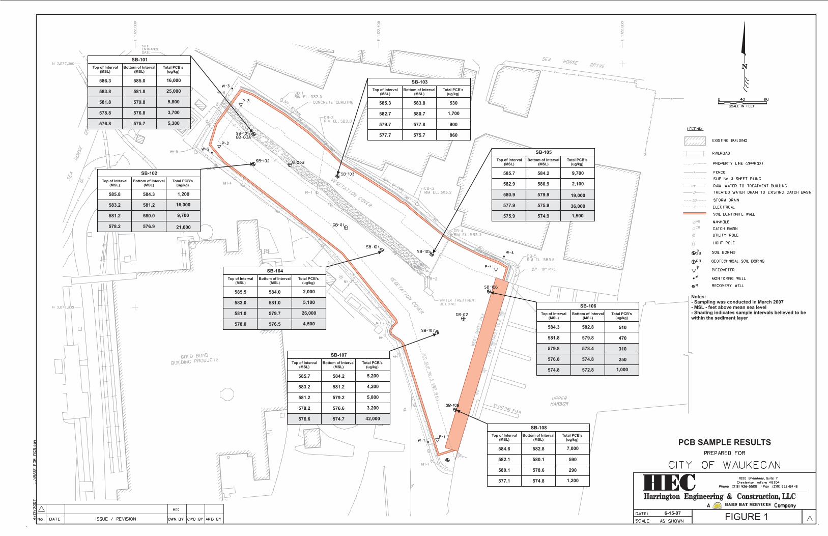
SB-101
Top of Interval(MSL)
Bottom of Interval(MSL)
Total PCB’s(ug/kg)
586.3
583.8
581.8
578.8
576.8
585.0
581.8
579.8
576.8
575.7
16,000
25,000
5,800
3,700
5,300
SB-107
Top of Interval(MSL)
Bottom of Interval(MSL)
Total PCB’s(ug/kg)
585.7
583.2
581.2
578.2
576.6
584.2
581.2
579.2
576.6
574.7
5,200
4,200
5,800
3,200
42,000
SB-106
Top of Interval(MSL)
Bottom of Interval(MSL)
Total PCB’s(ug/kg)
584.3
581.8
579.8
576.8
574.8
582.8
579.8
578.4
574.8
572.8
510
470
310
250
1,000
SB-105
Top of Interval(MSL)
Bottom of Interval(MSL)
Total PCB’s(ug/kg)
585.7
582.9
580.9
577.9
575.9
584.2
580.9
579.9
575.9
574.9
9,700
2,100
19,000
36,000
1,500
SB-102
Top of Interval(MSL)
Bottom of Interval(MSL)
Total PCB’s(ug/kg)
585.8
583.2
581.2
578.2
584.3
581.2
580.0
576.9
1,200
16,000
9,700
21,000
SB-103
Top of Interval(MSL)
Bottom of Interval(MSL)
Total PCB’s(ug/kg)
585.3
582.7
579.7
577.7
583.8
580.7
577.8
575.7
530
1,700
900
860
SB-104
Top of Interval(MSL)
Bottom of Interval(MSL)
Total PCB’s(ug/kg)
585.5
583.0
581.0
578.0
584.0
581.0
579.7
576.5
2,000
5,100
26,000
4,500
SB-108
Top of Interval(MSL)
Bottom of Interval(MSL)
Total PCB’s(ug/kg)
584.6
582.1
580.1
577.1
582.8
580.1
578.6
574.8
7,000
590
290
1,200
6-15-07FIGURE 1
Notes:- Sampling was conducted in March 2007- MSL - feet above mean sea level- Shading indicates sample intervals believed to bewithin the sediment layer
PCB SAMPLE RESULTS

Technical Memorandum Waukegan Harbor – Slip 3 Field Sampling Results
Attachment A Soil Boring Logs
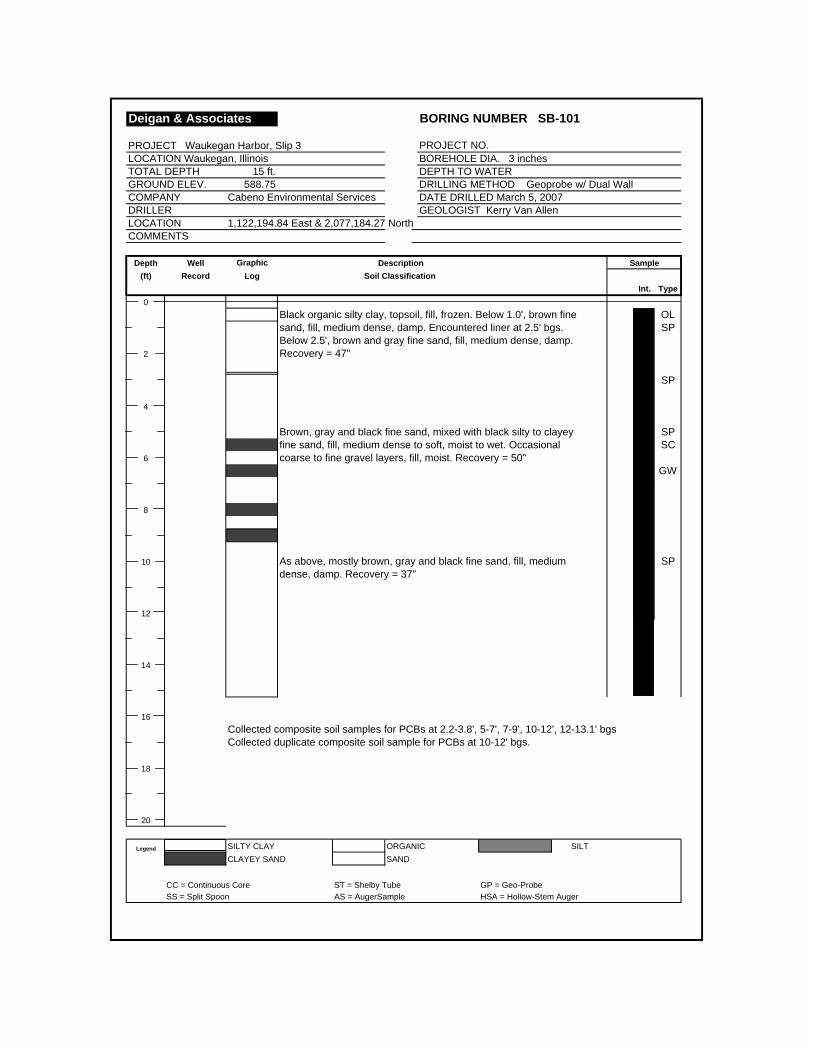
Deigan & Associates BORING NUMBER SB-101
PROJECT Waukegan Harbor, Slip 3 PROJECT NO. LOCATION Waukegan, Illinois BOREHOLE DIA. 3 inches TOTAL DEPTH 15 ft. DEPTH TO WATER GROUND ELEV. 588.75 DRILLING METHOD Geoprobe w/ Dual WallCOMPANY Cabeno Environmental Services DATE DRILLED March 5, 2007DRILLER GEOLOGIST Kerry Van AllenLOCATION 1,122,194.84 East & 2,077,184.27 NorthCOMMENTS
Depth Well Graphic Description Sample(ft) Record Log Soil Classification
Int. Type0
Black organic silty clay, topsoil, fill, frozen. Below 1.0', brown fine OLsand, fill, medium dense, damp. Encountered liner at 2.5' bgs. SPBelow 2.5', brown and gray fine sand, fill, medium dense, damp.
2 Recovery = 47"
SP
4
Brown, gray and black fine sand, mixed with black silty to clayey SPfine sand, fill, medium dense to soft, moist to wet. Occasional SC
6 coarse to fine gravel layers, fill, moist. Recovery = 50"GW
8
10 As above, mostly brown, gray and black fine sand, fill, medium SPdense, damp. Recovery = 37"
12
14
16Collected composite soil samples for PCBs at 2.2-3.8', 5-7', 7-9', 10-12', 12-13.1' bgsCollected duplicate composite soil sample for PCBs at 10-12' bgs.
18
20
Legend SILTY CLAY ORGANIC SILTCLAYEY SAND SAND
CC = Continuous Core ST = Shelby Tube GP = Geo-ProbeSS = Split Spoon AS = AugerSample HSA = Hollow-Stem Auger

Deigan & Associates BORING NUMBER SB-102
PROJECT Waukegan Harbor, Slip 3 PROJECT NO. LOCATION Waukegan, Illinois BOREHOLE DIA. 3 Inches TOTAL DEPTH 15 ft. DEPTH TO WATERGROUND ELEV. 588.19 DRILLING METHOD Geoprobe w/ Dual WallCOMPANY Cabeno Environmental Services DATE DRILLED March 5, 2007DRILLER GEOLOGIST Kerry Van AllenLOCATION 1,122,194.73 East & 2,077,135.05 NorthCOMMENTS
Depth Well Graphic Description Sample(ft) Record Log Soil Classification
Int. USCS0
Black organic silty clay, topsoil, fill, frozen. Below 1.0', brown fine OLsand, fill, medium dense, moist. Encountered liner at 2.4' bgs. SPBelow 2.4', gray fine sand, fill, medium dense, damp.
2 Recovery = 47"
SP
4
As above, fill, medium dense, damp. Below 5.5', gray fine sand, SPfill, mixed with black silty to clayey fine sand, soft, wet. SC
6 Recovery = 38"
8
10 As above, damp. Below 11.7', black silty to clayey fine sand, very SPsoft, wet. Recovery = 16" SC
12
14
16Collected composite soil samples for PCBs at 2.4-3.9', 5-7', 7-8.2', 10-11.3' bgsCollected duplicate composite soil sample for PCBs at 7-8.2' bgs.Collected field blank sample using pre-bagged clean medium grain sand, mixed in stainless
18 bowl.
20
Legend SILTY CLAY Organic topsoil SILTCLAYEY SAND SAND
CC = Continuous Core ST = Shelby Tube GP = Geo-ProbeSS = Split Spoon AS = AugerSample HSA = Hollow-Stem Auger

Deigan & Associates BORING NUMBER SB-103
PROJECT Waukegan Harbor, Slip 3 PROJECT NO. LOCATION Waukegan, Illinois BOREHOLE DIA. 3 inches TOTAL DEPTH 15 ft. DEPTH TO WATER GROUND ELEV. 587.72 DRILLING METHOD Geoprobe w/ Dual WallCOMPANY Cabeno Environmental Services DATE DRILLED March 5, 2007DRILLER GEOLOGIST Kerry Van AllenLOCATION 1,122,332.37 East & 2,077,114.96 NorthCOMMENTS
Depth Well Graphic Description Sample(ft) Record Log Soil Classification
Int. USCS0
Black organic silty clay, topsoil, fill, frozen. Below 0.8', brown fine OLsand, fill, medium dense, damp. Liner encountered at 2.4' bgs. SPBelow 2.4', brown and gray fine sand, medium dense, damp.
2 Recovery = 47"
SP
4
As above, becoming gray fine sand, fill, medium dense, damp. SPRecovery = 58"
6
8
10 As above, gray fine sand, fill, medium dense, damp. SPRecovery = 28"
12
14
16Collected composite soil samples for PCBs at 2.4-3.9', 5-7', 8-9.9', 10-12' bgs
18
20
Legend SILTY CLAY Organic topsoil SILTCLAYEY SAND SAND
CC = Continuous Core ST = Shelby Tube GP = Geo-ProbeSS = Split Spoon AS = AugerSample HSA = Hollow-Stem Auger

Deigan & Associates BORING NUMBER SB-104
PROJECT Waukegan Harbor, Slip 3 PROJECT NO. LOCATION Waukegan, Illinois BOREHOLE DIA. 3 inches TOTAL DEPTH 15 ft. DEPTH TO WATER GROUND ELEV. 588.04 DRILLING METHOD Geoprobe w/ Dual WallCOMPANY Cabeno Environmental Services DATE DRILLED March 5, 2007DRILLER GEOLOGIST Kerry Van AllenLOCATION 1,122,404.90 East & 2,076,994.23 NorthCOMMENTS
Depth Well Graphic Description Sample(ft) Record Log Soil Classification
Int. USCS0
Black organic silty clay, topsoil, fill, frozen. Below 1.0', brown fine OLsand, fill, medium dense, moist. Encountered liner at 2.5' bgs. SPBelow 2.5', gray fine sand, fill, medium dense, damp.
2 Recovery = 49"
SP
4
Gray fine sand mixed with black silty to clayey fine sand, fill, soft SPto medium dense, moist to wet. Recovery = 40" SC
6
8
10 Gray and black fine sand, fill, medium dense, damp. SPRecovery = 18"
12
14
16
Collected composite soil samples for PCBs at 2.5-4.0', 5-7', 7-8.3', 10-11.5' bgs Collected duplicate composite soil sample for PCBs at 2.5-4.0'
18
20
Legend SILTY CLAY Organic topsoil SILTCLAYEY SAND SAND
CC = Continuous Core ST = Shelby Tube GP = Geo-ProbeSS = Split Spoon AS = AugerSample HSA = Hollow-Stem Auger

Deigan & Associates BORING NUMBER SB-105
PROJECT Waukegan Harbor, Slip 3 PROJECT NO. LOCATION Waukegan, Illinois BOREHOLE DIA. 3 inches TOTAL DEPTH 15 ft. DEPTH TO WATER GROUND ELEV. 587.87 DRILLING METHOD Geoprobe w/ Dual WallCOMPANY Cabeno Environmental Services DATE DRILLED March 5, 2007DRILLER GEOLOGIST Kerry Van AllenLOCATION 1,122,487.30 East & 2,076,986.79 NorthCOMMENTS
Depth Well Graphic Description Sample(ft) Record Log Soil Classification
Int. Type0
Black organic silty clay, topsoil, fill, frozen. Below 0.8', brown fine OLsand, fill, medium dense, damp. Encountered liner at 2.2' bgs. SPBelow 2.2', gray fine sand, fill, medium dense, damp.
2 Recovery = 45"SP
4
As above, becoming dark gray and black fine sand below 6.2'. SPMixed with black silty to clayey fine sand, fill, soft, wet.
6 Recovery = 36"SC
8
10 Black silty to clayey fine sand, fill, soft, wet. Below 11.3', brown SCand gray fine sand, fill, damp. Recovery = 35"
SP
12
14
16Collected composite soil samples for PCBs at 2.2-3.7', 5-7', 7-8', 10-12', 12-13' bgsCollected field blank using pre-bagged clean medium grain sand, mixed in stainlesssteel bowl.
18
20
Legend SILTY CLAY ORGANIC SILTCLAYEY SAND SAND
CC = Continuous Core ST = Shelby Tube GP = Geo-ProbeSS = Split Spoon AS = AugerSample HSA = Hollow-Stem Auger

Deigan & Associates BORING NUMBER SB-106
PROJECT Waukegan Harbor, Slip 3 PROJECT NO. LOCATION Waukegan, Illinois BOREHOLE DIA. 3 Inches TOTAL DEPTH 15 ft. DEPTH TO WATERGROUND ELEV. 586.82 DRILLING METHOD Geoprobe w/ Dual WallCOMPANY Cabeno Environmental Services DATE DRILLED March 5, 2007DRILLER GEOLOGIST Kerry Van AllenLOCATION 1,122,580.99 East & 2,076,926.13 NorthCOMMENTS
Depth Well Graphic Description Sample(ft) Record Log Soil Classification
Int. USCS0
Black organic silty clay, topsoil, fill, frozen. Below 0.8', brown fine OLsand, fill, medium dense, moist. Encountered liner at 2.4' bgs. SPBelow 2.4', gray fine sand, fill, medium dense, damp.
2 Recovery = 49"
4
As above, fill, medium dense, damp. From 7.5 to 7.8', black silty to SPclayey fine sand, soft, wet. Recovery = 41"
6
SC
8
10 As above, gray fine sand with black silty to clayey fine sand layers, SPmoist to wet. Below 12.7', gray silty clay, fill, mixed with gray fine SCsand, moist. Recovery = 47"
12CLSP
14
16Collected composite soil samples for PCBs at 2.5-4.0', 5-7', 7-8.4', 10-12', 12-14' bgsCollected duplicate composite soil sample for PCBs at 5-7' bgs
18
20
Legend SILTY CLAY Organic topsoil SILTCLAYEY SAND SAND
CC = Continuous Core ST = Shelby Tube GP = Geo-ProbeSS = Split Spoon AS = AugerSample HSA = Hollow-Stem Auger
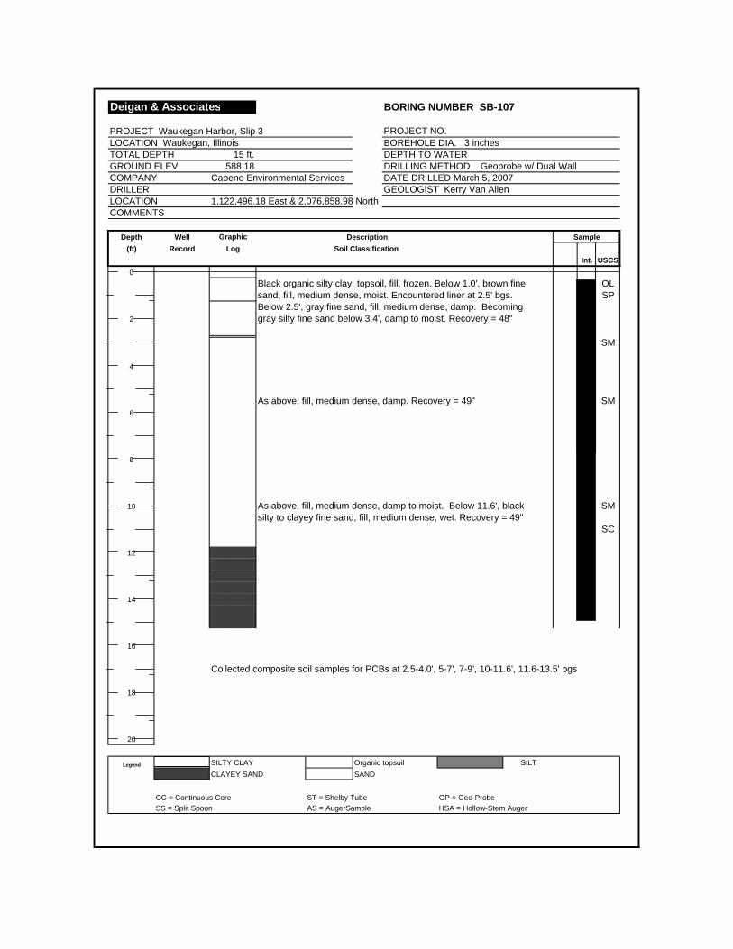
Deigan & Associates BORING NUMBER SB-107
PROJECT Waukegan Harbor, Slip 3 PROJECT NO. LOCATION Waukegan, Illinois BOREHOLE DIA. 3 inches TOTAL DEPTH 15 ft. DEPTH TO WATER GROUND ELEV. 588.18 DRILLING METHOD Geoprobe w/ Dual WallCOMPANY Cabeno Environmental Services DATE DRILLED March 5, 2007DRILLER GEOLOGIST Kerry Van AllenLOCATION 1,122,496.18 East & 2,076,858.98 NorthCOMMENTS
Depth Well Graphic Description Sample(ft) Record Log Soil Classification
Int. USCS0
Black organic silty clay, topsoil, fill, frozen. Below 1.0', brown fine OLsand, fill, medium dense, moist. Encountered liner at 2.5' bgs. SPBelow 2.5', gray fine sand, fill, medium dense, damp. Becoming
2 gray silty fine sand below 3.4', damp to moist. Recovery = 48"
SM
4
As above, fill, medium dense, damp. Recovery = 49" SM6
8
10 As above, fill, medium dense, damp to moist. Below 11.6', black SMsilty to clayey fine sand, fill, medium dense, wet. Recovery = 49"
SC
12
14
16
Collected composite soil samples for PCBs at 2.5-4.0', 5-7', 7-9', 10-11.6', 11.6-13.5' bgs
18
20
Legend SILTY CLAY Organic topsoil SILTCLAYEY SAND SAND
CC = Continuous Core ST = Shelby Tube GP = Geo-ProbeSS = Split Spoon AS = AugerSample HSA = Hollow-Stem Auger
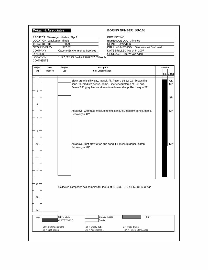
Deigan & Associates BORING NUMBER SB-108
PROJECT Waukegan Harbor, Slip 3 PROJECT NO. LOCATION Waukegan, Illinois BOREHOLE DIA. 3 inches TOTAL DEPTH 15 ft. DEPTH TO WATER GROUND ELEV. 587.07 DRILLING METHOD Geoprobe w/ Dual WallCOMPANY Cabeno Environmental Services DATE DRILLED March 5, 2007DRILLER GEOLOGIST Kerry Van AllenLOCATION 1,122,525.49 East & 2,076,732.03 NorthCOMMENTS
Depth Well Graphic Description Sample(ft) Record Log Soil Classification
Int. USCS0
Black organic silty clay, topsoil, fill, frozen. Below 0.7', brown fine OLsand, fill, medium dense, damp. Liner encountered at 2.4' bgs. SPBelow 2.4', gray fine sand, medium dense, damp. Recovery = 52"
2
SP
4
As above, with trace medium to fine sand, fill, medium dense, damp. SPRecovery = 42"
6
8
10 As above, light gray to tan fine sand, fill, medium dense, damp. SPRecovery = 28"
12
14
16Collected composite soil samples for PCBs at 2.5-4.3', 5-7', 7-8.5', 10-12.3' bgs
18
20
Legend SILTY CLAY Organic topsoil SILTCLAYEY SAND SAND
CC = Continuous Core ST = Shelby Tube GP = Geo-ProbeSS = Split Spoon AS = AugerSample HSA = Hollow-Stem Auger

Deigan & Associates BORING NUMBER GB-01
PROJECT Waukegan Harbor, Slip 3 PROJECT NO. LOCATION Waukegan, Illinois BOREHOLE DIA. 3 Inches TOTAL DEPTH 25 ft. DEPTH TO WATERGROUND ELEV. 588.32 DRILLING METHOD Geoprobe w/ Dual WallCOMPANY Cabeno Environmental Services DATE DRILLED March 6, 2007DRILLER GEOLOGIST Kerry Van AllenLOCATION 1,122,346.38 East & 2,077,030.92 NorthCOMMENTS
Depth Well Graphic Description Sample(ft) Record Log Soil Classification
Int. USCS0
Black organic silty clay, topsoil, fill, frozen. Below 1.0', brown fine OLsand, fill, medium dense, moist. Encountered liner at 2.7' bgs. SPBelow 2.7', brown fine sand, fill, medium dense, damp. Below 4.2',
2 gray fine sand, fill, medium dense, damp. Recovery = 54"
SP
4 SP
Gray fine sand mixed with black silty to clayey fine sand, fill, SPmedium dense to soft, damp to wet. Becoming mostly black silty SC
6 to clayey fine sand below 7.2', soft, wet. Recovery = 41"
SC8
10 Black silty to clayey fine sand, fill, soft, wet. Below 10.3', gray fine SCsand, fill, medium dense, damp. Recovery = 44" SP
12
14
Gray fine sand mixed with black silty to clayey fine sand, fill, SPmedium dense to soft, moist to wet. Below 17.1', gray fine sand, SC
16 natural, medium dense, saturated.
SP18
20
Legend SILTY CLAY Organic topsoil SILTCLAYEY SAND SAND
CC = Continuous Core ST = Shelby Tube GP = Geo-ProbeSS = Split Spoon AS = AugerSample HSA = Hollow-Stem Auger
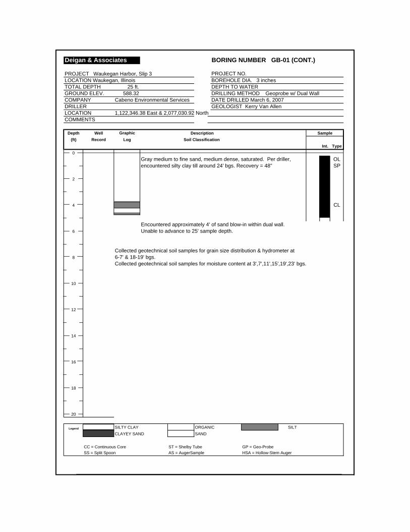
Deigan & Associates BORING NUMBER GB-01 (CONT.)
PROJECT Waukegan Harbor, Slip 3 PROJECT NO. LOCATION Waukegan, Illinois BOREHOLE DIA. 3 inches TOTAL DEPTH 25 ft. DEPTH TO WATER GROUND ELEV. 588.32 DRILLING METHOD Geoprobe w/ Dual WallCOMPANY Cabeno Environmental Services DATE DRILLED March 6, 2007DRILLER GEOLOGIST Kerry Van AllenLOCATION 1,122,346.38 East & 2,077,030.92 NorthCOMMENTS
Depth Well Graphic Description Sample(ft) Record Log Soil Classification
Int. Type0
Gray medium to fine sand, medium dense, saturated. Per driller, OLencountered silty clay till around 24' bgs. Recovery = 48" SP
2
4 CL
Encountered approximately 4' of sand blow-in within dual wall. 6 Unable to advance to 25' sample depth.
Collected geotechnical soil samples for grain size distribution & hydrometer at 8 6-7' & 18-19' bgs.
Collected geotechnical soil samples for moisture content at 3',7',11',15',19',23' bgs.
10
12
14
16
18
20
Legend SILTY CLAY ORGANIC SILTCLAYEY SAND SAND
CC = Continuous Core ST = Shelby Tube GP = Geo-ProbeSS = Split Spoon AS = AugerSample HSA = Hollow-Stem Auger

Deigan & Associates BORING NUMBER GB-02
PROJECT Waukegan Harbor, Slip 3 PROJECT NO. LOCATION Waukegan, Illinois BOREHOLE DIA. 3 inches TOTAL DEPTH 25 ft. DEPTH TO WATER GROUND ELEV. 587.92 DRILLING METHOD Geoprobe w/ Dual WallCOMPANY Cabeno Environmental Services DATE DRILLED March 6, 2007DRILLER GEOLOGIST Kerry Van AllenLOCATION 1,122,538.95 East & 2,076,881.56 NorthCOMMENTS
Depth Well Graphic Description Sample(ft) Record Log Soil Classification
Int. USCS0
Black organic silty clay, topsoil, fill, frozen. Below 1.1', brown fine OLsand, fill, medium dense, moist. Encountered liner at 2.2' bgs. SPBelow 2.2', brown fine sand, fill, medium dense, damp. Below 2.8',
2 gray medium to fine sand mixed with black silty fine sand, fill,medium dense, damp.
SM
4
Gray fine sand, fill, medium dense, damp. Recovery = 53" SP
6
8
10 As above, gray fine sand, fill, medium dense, damp. Recovery = 29" SP
12
14
Black silty to clayey fine sand, fill, soft, wet. Recovery = 60" SC
16
18
20
Legend SILTY CLAY Organic topsoil SILTCLAYEY SAND SAND
CC = Continuous Core ST = Shelby Tube GP = Geo-ProbeSS = Split Spoon AS = AugerSample HSA = Hollow-Stem Auger
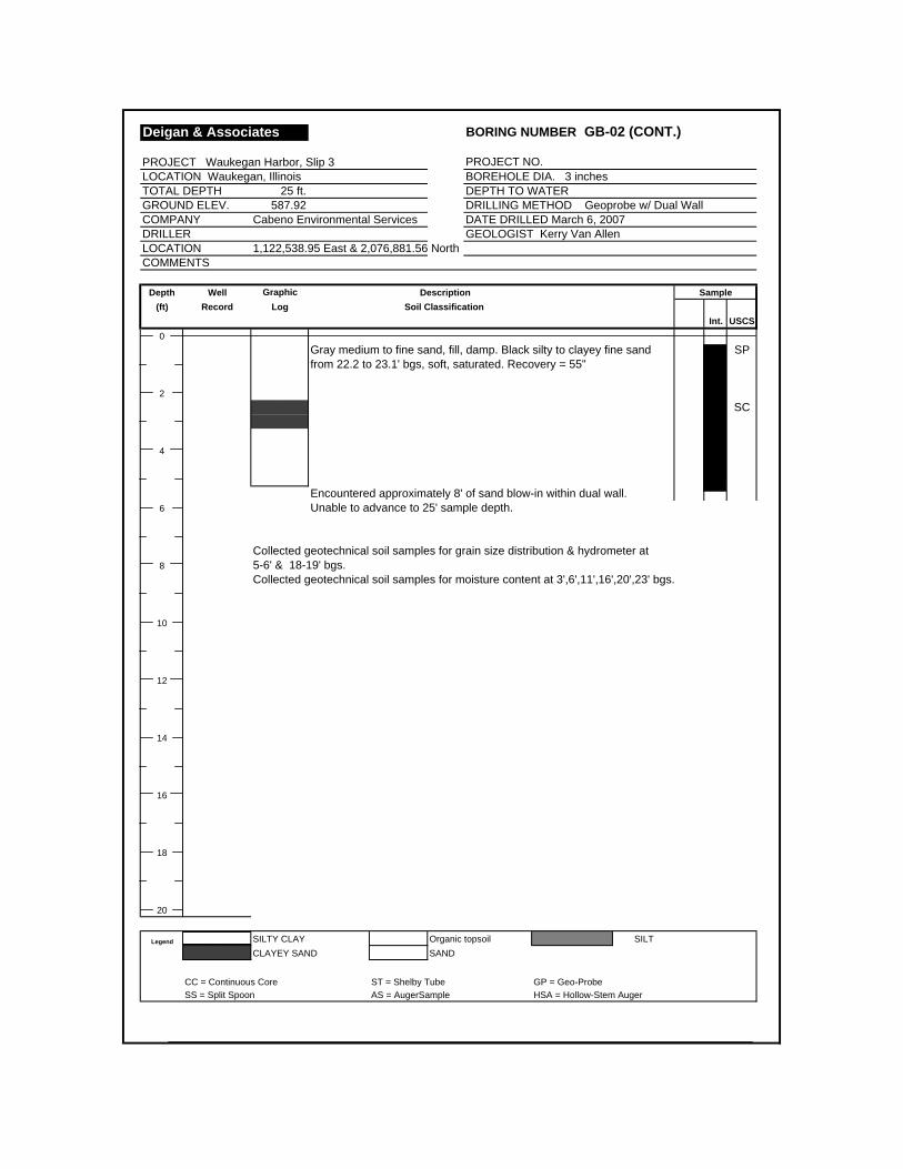
Deigan & Associates BORING NUMBER GB-02 (CONT.)
PROJECT Waukegan Harbor, Slip 3 PROJECT NO. LOCATION Waukegan, Illinois BOREHOLE DIA. 3 inches TOTAL DEPTH 25 ft. DEPTH TO WATER GROUND ELEV. 587.92 DRILLING METHOD Geoprobe w/ Dual WallCOMPANY Cabeno Environmental Services DATE DRILLED March 6, 2007DRILLER GEOLOGIST Kerry Van AllenLOCATION 1,122,538.95 East & 2,076,881.56 NorthCOMMENTS
Depth Well Graphic Description Sample(ft) Record Log Soil Classification
Int. USCS0
Gray medium to fine sand, fill, damp. Black silty to clayey fine sand SPfrom 22.2 to 23.1' bgs, soft, saturated. Recovery = 55"
2SC
4
Encountered approximately 8' of sand blow-in within dual wall. 6 Unable to advance to 25' sample depth.
Collected geotechnical soil samples for grain size distribution & hydrometer at 8 5-6' & 18-19' bgs.
Collected geotechnical soil samples for moisture content at 3',6',11',16',20',23' bgs.
10
12
14
16
18
20
Legend SILTY CLAY Organic topsoil SILTCLAYEY SAND SAND
CC = Continuous Core ST = Shelby Tube GP = Geo-ProbeSS = Split Spoon AS = AugerSample HSA = Hollow-Stem Auger

Deigan & Associates BORING NUMBER GB-03
PROJECT Waukegan Harbor, Slip 3 PROJECT NO. LOCATION Waukegan, Illinois BOREHOLE DIA. 3 inches TOTAL DEPTH 25 ft. DEPTH TO WATER GROUND ELEV. 588.89 DRILLING METHOD Geoprobe w/ Dual WallCOMPANY Cabeno Environmental Services DATE DRILLED March 6, 2007DRILLER GEOLOGIST Kerry Van AllenLOCATION 1,122,254.31 East & 2,077,133.89 NorthCOMMENTS
Depth Well Graphic Description Sample(ft) Record Log Soil Classification
Int. USCS0
Black organic silty clay, topsoil, fill, frozen. Below 1.1', brown fine OLsand, fill, medium dense, moist. Encountered liner at 2.5' bgs. SPBelow 2.5', brown fine sand, fill, medium dense, damp. Below 3.7',
2 light gray fine sand, fill, medium dense, damp. Recovery = 49"
4
Gray fine sand, fill, loose, damp. Poor recovery. Recovery = 3" SP
6
8
10 As above, gray fine sand, fill, loose. Poor recovery. Recovery = 4" SP
12
14
As above, gray fine sand, fill, loose. Poor recovery. Recovery = 3" SP
16
18
20
Legend SILTY CLAY Organic topsoil SILTCLAYEY SAND SAND
CC = Continuous Core ST = Shelby Tube GP = Geo-ProbeSS = Split Spoon AS = AugerSample HSA = Hollow-Stem Auger
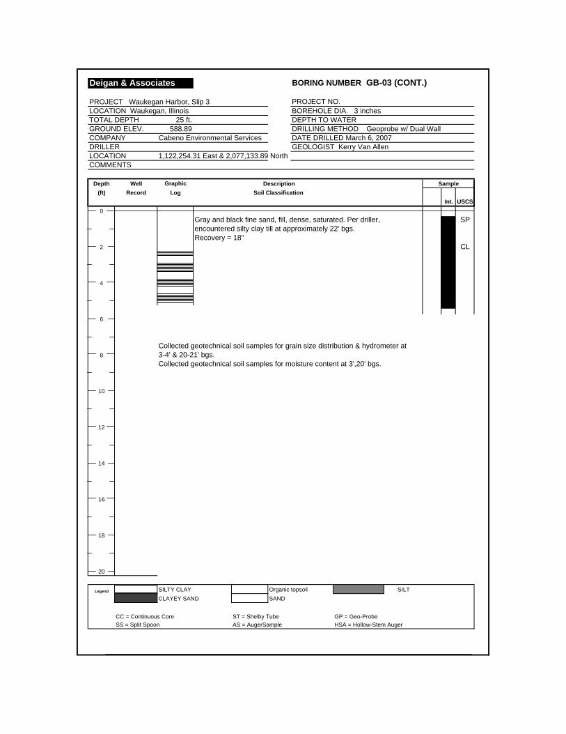
Deigan & Associates BORING NUMBER GB-03 (CONT.)
PROJECT Waukegan Harbor, Slip 3 PROJECT NO. LOCATION Waukegan, Illinois BOREHOLE DIA. 3 inches TOTAL DEPTH 25 ft. DEPTH TO WATER GROUND ELEV. 588.89 DRILLING METHOD Geoprobe w/ Dual WallCOMPANY Cabeno Environmental Services DATE DRILLED March 6, 2007DRILLER GEOLOGIST Kerry Van AllenLOCATION 1,122,254.31 East & 2,077,133.89 NorthCOMMENTS
Depth Well Graphic Description Sample(ft) Record Log Soil Classification
Int. USCS0
Gray and black fine sand, fill, dense, saturated. Per driller, SPencountered silty clay till at approximately 22' bgs. Recovery = 18"
2 CL
4
6
Collected geotechnical soil samples for grain size distribution & hydrometer at 8 3-4' & 20-21' bgs.
Collected geotechnical soil samples for moisture content at 3',20' bgs.
10
12
14
16
18
20
Legend SILTY CLAY Organic topsoil SILTCLAYEY SAND SAND
CC = Continuous Core ST = Shelby Tube GP = Geo-ProbeSS = Split Spoon AS = AugerSample HSA = Hollow-Stem Auger

Technical Memorandum Waukegan Harbor – Slip 3 Field Sampling Results
Attachment B Cone Penetrometer Soundings


Technical Memorandum Waukegan Harbor – Slip 3 Field Sampling Results
Attachment C Photographic Log

Deigan & Associates, LLC
Soil Investigation Activities – Week of March 5th, 2007Slip 3, Waukegan Harbor, Waukegan, IL
Photo 1 – CPT soil investigation at the GB-02 location.
Photo 2 – Close-up view of CPT investigative tooling and equipment.

Deigan & Associates, LLC
Soil Investigation Activities – Week of March 5th, 2007Slip 3, Waukegan Harbor, Waukegan, IL
Photo 3 – Evaluation of CPT data (left) at the GB-02 location.
Photo 4 –CPT investigative work at the GB-01 location.
Deigan & Associates, LLC
Soil Investigation Activities – Week of March 5th, 2007Slip 3, Waukegan Harbor, Waukegan, IL
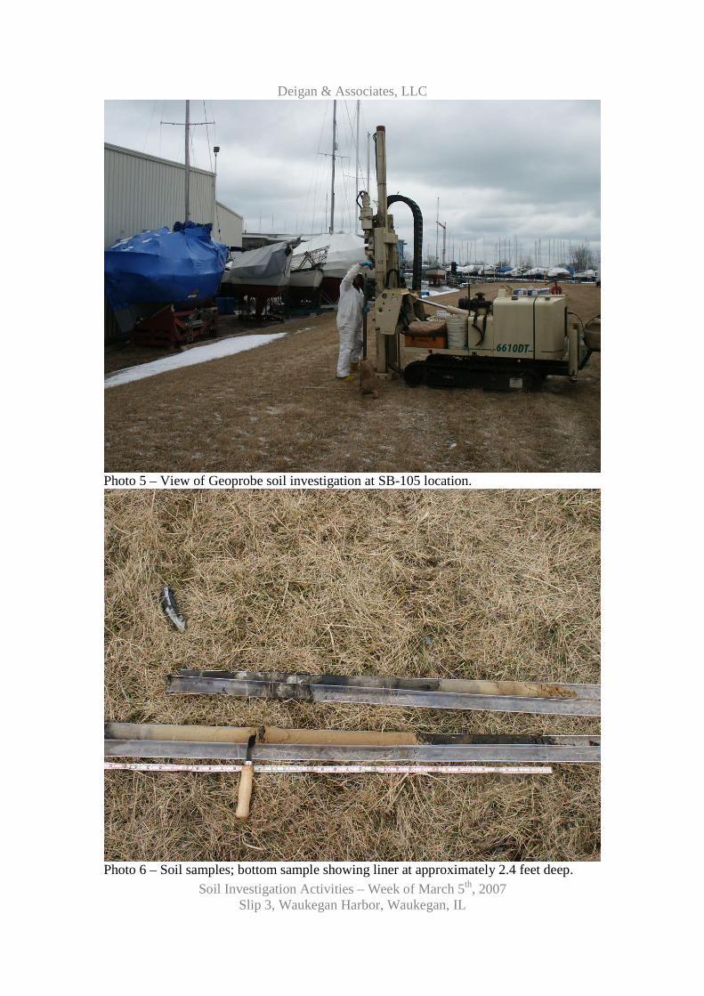
Photo 5 – View of Geoprobe soil investigation at SB-105 location.
Photo 6 – Soil samples; bottom sample showing liner at approximately 2.4 feet deep.
Deigan & Associates, LLC
Soil Investigation Activities – Week of March 5th, 2007Slip 3, Waukegan Harbor, Waukegan, IL
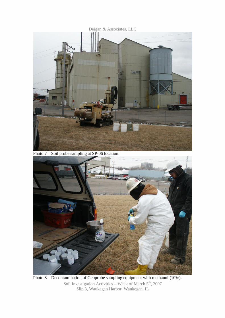
Photo 7 – Soil probe sampling at SP-06 location.
Photo 8 – Decontamination of Geoprobe sampling equipment with methanol (10%).

Deigan & Associates, LLC
Soil Investigation Activities – Week of March 5th, 2007Slip 3, Waukegan Harbor, Waukegan, IL
Photo 9 – Soil samples extending to 25 feet deep (1st core on top, 5th core on bottom).
Photo 10 – Blow-in sands inside the outer casing at GB-02 location.

Deigan & Associates, LLC
Soil Investigation Activities – Week of March 5th, 2007Slip 3, Waukegan Harbor, Waukegan, IL
Photo 11 – Laboratory bottles used for soil samples. Sand used for field blanks (left).
Photo 12 – Close up view of clean (bagged) sand used for QA/QC field blank samples.
Deigan & Associates, LLC
Soil Investigation Activities – Week of March 5th, 2007Slip 3, Waukegan Harbor, Waukegan, IL
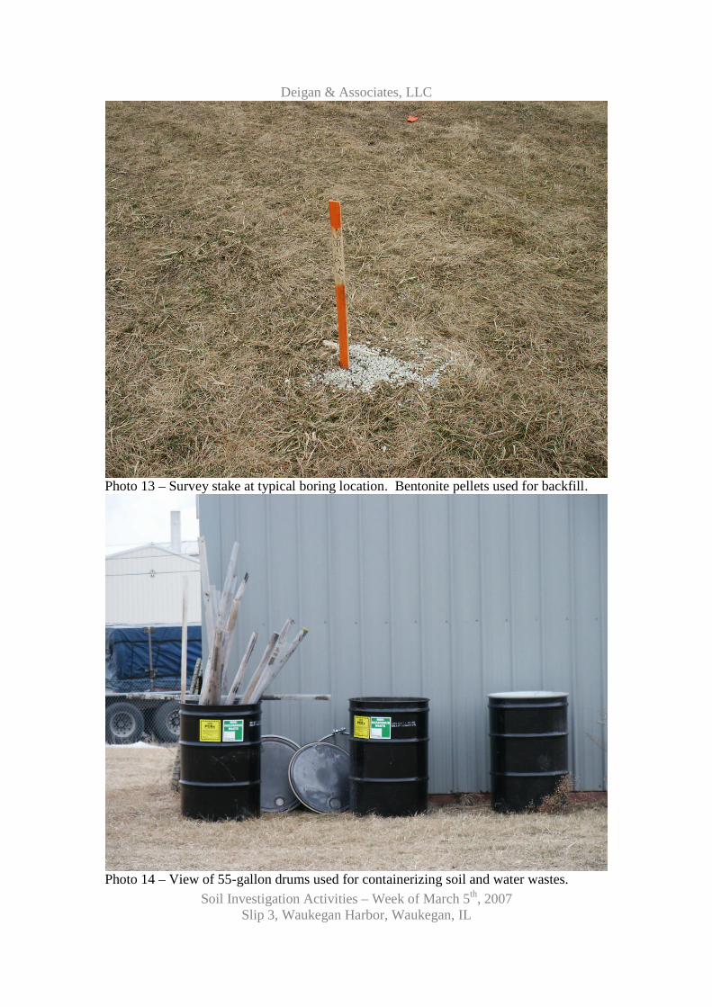
Photo 13 – Survey stake at typical boring location. Bentonite pellets used for backfill.
Photo 14 – View of 55-gallon drums used for containerizing soil and water wastes.

Technical Memorandum Waukegan Harbor – Slip 3 Field Sampling Results
Attachment D STL Analytical Reports