handovers - agilent
DESCRIPTION
Handover material from AgilentTRANSCRIPT
3/9/13 Handovers
wireless.agilent.com/rfcomms/refdocs/wcdma/wcdma_gen_call_handoffs.html 1/28
Show
Handovers
Last updated: October 19, 2012
The following handovers are available in the test set:
Physical Channel ReconfigurationTransport Channel Reconfiguration
System Handover ( GSM/GPRS_W-CDMA fast switching test and lab applications only )
Soft Handover ( lab application only )
Radio Bearer Reconfiguration ( lab application or feature-licensed test application only )
External 8960 Handover ( lab application only )
External PS Handover ( lab application only )
SRVCC Handover ( lab application only )
RRC Release with Redirect ( lab application only )
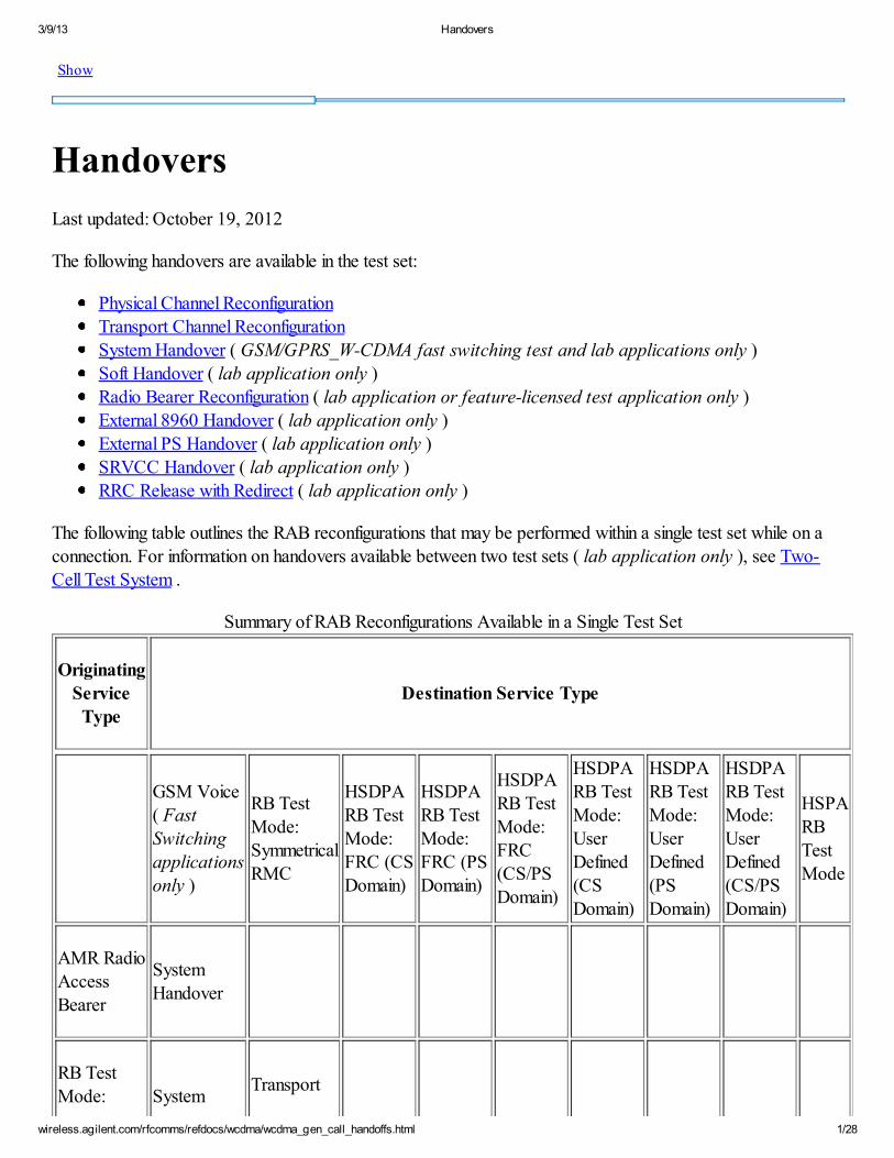
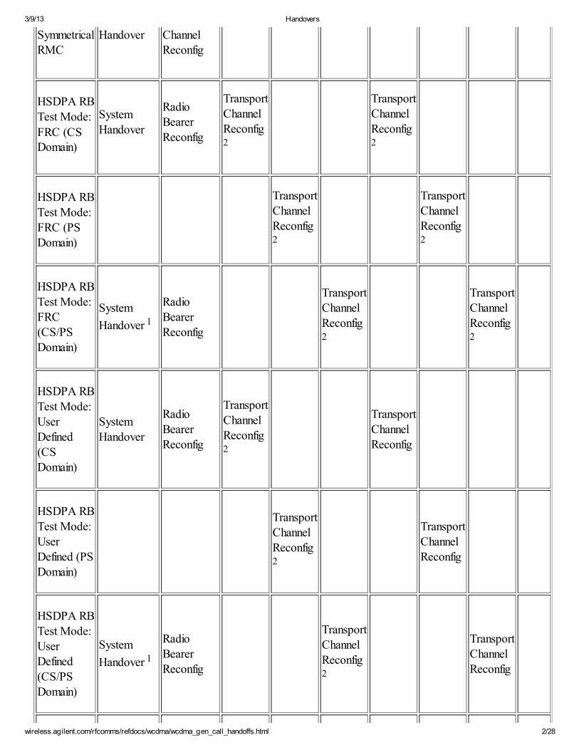
The following table outlines the RAB reconfigurations that may be performed within a single test set while on aconnection. For information on handovers available between two test sets ( lab application only ), see Two-
Cell Test System .
Summary of RAB Reconfigurations Available in a Single Test Set
Originating
ServiceType
Destination Service Type
GSM Voice
( Fast
Switchingapplications
only )
RB Test
Mode:
Symmetrical
RMC
HSDPA
RB Test
Mode: FRC (CS
Domain)
HSDPA
RB Test
Mode:FRC (PS
Domain)
HSDPARB Test
Mode:
FRC
(CS/PS
Domain)
HSDPA
RB Test
Mode:
UserDefined
(CS
Domain)
HSDPA
RB Test
Mode:
UserDefined
(PS
Domain)
HSDPA
RB Test
Mode:
UserDefined
(CS/PS
Domain)
HSPA
RB
Test
Mode
AMR Radio
Access
Bearer
System
Handover
RB Test
Mode: SystemTransport
3/9/13 Handovers
wireless.agilent.com/rfcomms/refdocs/wcdma/wcdma_gen_call_handoffs.html 2/28
SymmetricalRMC
Handover ChannelReconfig
HSDPA RB
Test Mode:
FRC (CSDomain)
System
Handover
Radio
Bearer
Reconfig
Transport
Channel
Reconfig2
Transport
Channel
Reconfig2
HSDPA RB
Test Mode:
FRC (PS
Domain)
Transport
Channel
Reconfig2
Transport
Channel
Reconfig2
HSDPA RB
Test Mode:FRC
(CS/PSDomain)
System
Handover 1
RadioBearer
Reconfig
Transport
ChannelReconfig2
Transport
ChannelReconfig2
HSDPA RBTest Mode:
UserDefined(CS
Domain)
SystemHandover
RadioBearer
Reconfig
Transport
ChannelReconfig2
TransportChannel
Reconfig
HSDPA RB
Test Mode:User
Defined (PSDomain)
Transport
ChannelReconfig2
TransportChannel
Reconfig
HSDPA RBTest Mode:User
Defined(CS/PS
Domain)
System
Handover 1
RadioBearer
Reconfig
Transport
ChannelReconfig2
TransportChannel
Reconfig
3/9/13 Handovers
wireless.agilent.com/rfcomms/refdocs/wcdma/wcdma_gen_call_handoffs.html 3/28
HSPA RB
Test ModeSystem
Handover
RadioBearerReconfig
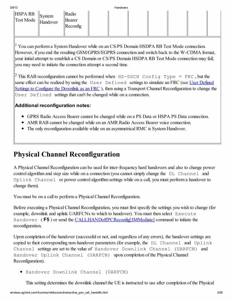
1 You can perform a System Handover while on an CS/PS Domain HSDPA RB Test Mode connection.However, if you end the resulting GSM/GPRS/EGPRS connection and switch back to the W-CDMA format,your initial attempt to establish a CS Domain or CS/PS Domain HSDPA RB Test Mode connection may fail;
you may need to initiate the connection attempt a second time.
2 This RAB reconfiguration cannot be performed when HS-DSCH Config Type = FRC , but thesame effect can be realized by using the User Defined settings to simulate an FRC (see User Defined
Settings to Configure the Downlink as an FRC ), then using a Transport Channel Reconfiguration to change theUser Defined settings that can't be changed while on a connection.
Additional reconfiguration notes:
GPRS Radio Access Bearer cannot be changed while on a PS Data or HSPA PS Data connection.
AMR RAB cannot be changed while on an AMR Radio Access Bearer voice connection.The only reconfiguration available while on an asymmetrical RMC is System Handover.
Physical Channel Reconfiguration
A Physical Channel Reconfiguration can be used for inter-frequency hard handovers and also to change powercontrol algorithm and step size while on a connection (you cannot simply change the DL Channel and
Uplink Channel or power control algorithm settings while on a call, you must perform a handover tochange them).
You must be on a call to perform a Physical Channel Reconfiguration.
Before executing a Physical Channel Reconfiguration, you must first specify the settings you wish to change (forexample, downlink and uplink UARFCNs to which to handover). You must then select Execute
Handover ( F5 ) or send the CALL:HANDoff:PCReconfig[:IMMediate] command to initiate thereconfiguration.
Upon completion of the handover (successful or not, and regardless of any errors), the handover settings are
copied to their corresponding non-handover parameters (for example, the DL Channel and Uplink
Channel settings are set to the value of Handover Downlink Channel (UARFCN) andHandover Uplink Channel (UARFCN) upon completion of the Physical Channel
Reconfiguration).
Handover Downlink Channel (UARFCN)
This setting determines the downlink channel the UE is instructed to use after completion of the Physical
3/9/13 Handovers
wireless.agilent.com/rfcomms/refdocs/wcdma/wcdma_gen_call_handoffs.html 4/28
Channel Reconfiguration. See DL Channel for more information.
GPIB command: CALL:SETup[:PCReconfig]:CHANnel<[:SELected]|:FDD>:DOWNlink .
You can specify the handover uplink UARFCN in one of two ways:
Handover Uplink Channel (UARFCN)
You can directly set the Handover Uplink Channel (UARFCN) setting to a specific
uplink UARFCN value. The UE is instructed to use this uplink channel after completion of the
Physical Channel Reconfiguration.
GPIB command:
CALL:SETup[:PCReconfig]:CHANnel<[:SELected]|:FDD>:UPLink[:MCHannel] .
Automatic handover uplink channel
When Handover Uplink Channel is set to Auto , the handover uplink UARFCN is
automatically determined by the Handover Downlink Channel (UARFCN) setting. The test set
subtracts the frequency separation associated with the handover downlink channel's band from theHandover Downlink Channel (UARFCN) setting, and instructs the UE to use this
uplink channel after completion of the Physical Channel Reconfiguration.
GPIB command:CALL:SETup[:PCReconfig]:CHANnel<[:SELected]|:FDD>:UPLink:CONTrol:AUTO
See Uplink Channel for more information.
Handover Band Arbitrator
When you set Handover Downlink Channel (UARFCN) to a value in Band VI, you must specify whether
you want the test set to send a Band V or Band VI Frequency Band Indicator using the HandoverBand Arbitrator setting. See Band Arbitrator for more information.
GPIB command: CALL:SETup[:PCReconfig]:CHANnel:BARBitrator
Handover UL CL Power Ctrl Algorithm
This setting determines the closed loop power control algorithm the UE is instructed to use after
completion of the Physical Channel Reconfiguration procedure. See UL CL Power Ctrl Algorithm formore information.
GPIB command: CALL:SETup:CLPControl:UPLink:ALGorithm
Handover UL CL Power Ctrl Step Size
This setting determines the power control step size the UE is instructed to use after completion of thePhysical Channel Reconfiguration procedure when Handover UL CL Power Ctrl Algorithm is set to
One . This setting can only be changed when Handover UL CL Power Ctrl Algorithm is set to One .
Also, if Handover UL CL Power Ctrl Algorithm is set to Two , this setting is returned to its default value
3/9/13 Handovers
wireless.agilent.com/rfcomms/refdocs/wcdma/wcdma_gen_call_handoffs.html 5/28
of 1 dB . See UL CL Power Ctrl Stepsize for more information .
GPIB command: CALL:SETup:CLPControl:UPLink:STEPsize
PCR Timing Indication (CFN Handling)
You can specify whether the UE should maintain or initialise its CFN counter when performing thePhysical Channel Reconfiguration. See RB setup Timing Indication (CFN Handling): for additional details.
Note that 3GPP 25.331 v5.17.0 s8.6.6.28 states that the UE's behavior is undefined if the network sets
the Timing Indication IE to Initialise on a non-hard handover (i.e. where the UARFCNs and one or more
Primary Scrambling Codes remain unchanged as part of the reconfiguration).
Auto: When PCR Timing Indication (CFN Handling) is set to Auto , the
Timing Indication information element sent in the Physical Channel Reconfiguration message is set to
Initialise if Handover Downlink Channel (UARFCN) and Handover Uplink Channel (UARFCN)are set such that a hard handover will occur (UARFCNs will change). Otherwise, the Timing
Indication information element sent in the Physical Channel Reconfiguration message is set to
Maintain.Initialise: the Timing Indication information element sent in the Physical Channel Reconfiguration
message is set to Initialise.
Maintain: the Timing Indication information element sent in the Physical Channel Reconfiguration
message is set to Maintain.
GPIB command: CALL:HANDoff:PCReconfig:CFNHandling .
RB Test Mode PCR Loopback Messaging State
You can specify whether the UE loopback is opened or closed as part of a Physical Channel
Reconfiguration. This parameter only affects the Physical Channel Reconfiguration procedure when an RB
Test Mode call is active (as the loopback is never closed on any other call type).
On : The test set sends an Open UE Test Loop message before sending the Physical Channel
Reconfiguration message and a Close UE Test Loop message after receiving the Physical Channel
Reconfiguration Complete message from the UE.
Note, opening and closing the UE test loop clears the UE's buffer and resets its loopback delay
(see BER Synchronization requirements ).
Note, if a Close UE Test Loop message is not sent to the UE when establishing an asymmetrical
RMC, you cannot send an Open UE Test Loop message as part of the Physical Channel
Reconfiguration (see Asymmetric RMC Loopback Messaging ). If RB Test Mode PCRLoopback Messaging State is set to On and Asymmetric RMC
Loopback Messaging is set to Off and the current connection is an asymmetrical
RMC, the test set will not send the Open/Close UE Test Loop messages.
Off : The test set does not send any loopback control messages as part of the Physical Channel
Reconfiguration procedure.
3/9/13 Handovers
wireless.agilent.com/rfcomms/refdocs/wcdma/wcdma_gen_call_handoffs.html 6/28
GPIB command: CALL:HANDoff:PCReconfig:RBTest:LMESsaging:STATe
PCR Activation Time
This parameter allows you to set the Activation Time that is signaled to the UE in the Physical Channel
Reconfiguration message (see 3GPP TS 25.331 s10.3.3.1). Activation Time controls the frame number at
which the operation caused by the related message shall take effect (in other words, how long the UEshould wait before moving to the new frequency). It can be set between 0 and 255, and indicates the
absolute value of the CFN (Connection Frame Number) at which the UE should perform the handover. If
set to 0, the Activation Time IE is not sent in the Physical Channel Reconfiguration message.
For most UEs, an Activation Time of 0 ("now") is appropriate. But for some UEs, the handover will fail if
Activation Time is left at its default value of 0, as explained in the following:
When the test set orders a Physical Channel Reconfiguration, it takes a finite amount of time for the testset to move to and settle at the new frequency. When the Physical Channel Reconfiguration is ordered,
most UEs wait a time of T312 at the new frequency before determining that the handover has failed (T312
is signalled by the test set in SIB1 with a value of 5 seconds). If your UE does not wait once moving to thenew frequency, the handover may fail. If it does, set the Activation Time as needed to cause the UE to
wait until the test set has moved to the new frequency (a setting of 100 (100 x 10 ms = 1 s) is usually
sufficient).
Do not set PCR Activation Time to a value other than 0 unless necessary, as it slows down
the handover procedure.
GPIB command: CALL:HANDoff:PCReconfig:ATIMe
Handover Dual Carrier Band Configuration
This parameter specifies whether the N th serving cell downlink UARFCN should use UARFCNs that arein the single band, dual band, or any customized band during the Physical Channel Reconfiguration
procedure.
GPIB command: CALL:SETup[:PCReconfig]:HSDPa:MCARrier:BAND:CONFig[:TYPE]
Handover Secondary Cell DL Channel Config
This parameter specifies whether Handover Secondary Cell DL Adjacent UARFCN or HandoverSecondary Cell DL Manual UARFCN is used as the UARFCN of the secondary serving cell for Physical
Channel Reconfiguration . This setting applies when Handover Dual Carrier Band Configuration is set to
Single Band .
GPIB command: CALL:SETup[:PCReconfig]:SSCell:CHANnel:CONFig[:TYPE]
Handover Secondary Cell DL Adjacent UARFCN
This parameter specifies the target downlink UARFCN of the secondary serving cell, whether to be
Higher or Lower compared to the serving cell by Physical Channel Reconfiguration . This setting
3/9/13 Handovers
wireless.agilent.com/rfcomms/refdocs/wcdma/wcdma_gen_call_handoffs.html 7/28
applies when Handover Dual Carrier Band Configuration is set to Single Band and HandoverSecondary Cell DL Channel Config is set to Adjacent .
GPIB command: CALL:SETup[:PCReconfig]:SSCell:CHANnel:ADJacent
Handover Secondary Cell DL Manual UARFCN
This parameter specifies the target downlink UARFCN of the secondary serving cell by Physical Channel
Reconfiguration . This setting is available when:
Handover Dual Carrier Band Configuration is set to Single Band and Handover Secondary
Cell DL Channel Config is set to Manual .
Handover Dual Carrier Band Configuration is set to Dual Band or User Defined .
GPIB command: CALL:SETup[:PCReconfig]:SSCell:CHANnel:MANual:UARFcn
Handover Secondary Cell Manual Band Arbitrator
This parameter determines whether the test set sends a Band V or Band VI Frequency Band Indicator.
See Band Arbitrator for more information.
This parameter is available when:
Handover Secondary Cell DL Channel Config is set to Manual .
Handover Dual Carrier Band Configuration is set as Single Band .Handover Secondary Cell DL Manual UARFCN is set to a value (1037, 1062, 4387 to 4413)
shared by Band V and Band VI UARFCNs.
GPIB command: CALL:SETup[:PCReconfig]:SSCell:CHANnel:MANual:BARBitrator
PCR MCC (Mobile Country Code)
This parameter specifies the Mobile Country Code that is signalled to the UE during the Physical Channel
Reconfiguration procedure.
GPIB command: CALL:SETup[:PCReconfig]:MCCode
Handover MNC (Mobile Network Code)
This parameter specifies the Mobile Network Code that is signalled to the UE during the Physical ChannelReconfiguration procedure.
GPIB command: CALL:SETup[:PCReconfig]:MNCode
Handover MNC (Mobile Network Code) Length
This parameter specifies the length of Handover MNC (Mobile Network Code) .
When Handover MNC (Mobile Network Code) Length is set to Auto , the
3/9/13 Handovers
wireless.agilent.com/rfcomms/refdocs/wcdma/wcdma_gen_call_handoffs.html 8/28
MNC will be transmitted in 2 digits if the MNC is less or equal to 99 and 3 digits otherwise.When Handover MNC (Mobile Network Code) Length is set to 3 Digits ,
the MNC will be transmitted in 3 digits, prepending one or two zeros if necessary.
GPIB command: CALL:SETup[:PCReconfig]:MNCode:LENGth
PCR N_cqi_typeA/M_cqi ratio
When the Current MIMO Configuration Status is set to Active , this parametercontrols the N_cqi_typeA/M_cqi Ratio on the UL HS-DPCCH that is signalled to the UE during the
Physical Channel Reconfiguration procedure.
GPIB command: CALL:SETup[:PCReconfig]:MIMO:NMRatio
PCR HSDPA MIMO Antenna 2 Pilot Configuration
When the Current MIMO Configuration Status is set to Active , this parameter
controls the pilot channel the UE uses for the antenna 2 that is signalled to the UE during the Physical
Channel Reconfiguration procedure.
GPIB command: CALL:SETup[:PCReconfig]:ANTenna2:PILot:CONFig
Physical Channel Reconfiguration Operating Considerations
In order for an inter-frequency hard handover to be successful, some UEs may require that you include
the handover downlink channel in the SIB11 Inter-Freq Cell Info List (see Inter-
frequency Cells ).
Any measurements that have been initiated are aborted when a Physical Channel Reconfiguration is
initiated.
If the handover downlink and uplink channels result in an UL/DL offset of less than 30 MHz, the warning
message "Performance not specified for UL/DL frequency offset <30 MHz" is issued.
Transport Channel Reconfiguration
The Transport Channel Reconfiguration provides three main functions:
Switching Between Symmetrical RMCs while on an RB Test Mode ConnectionChanging Parameters that Require Cell Off Operating Mode or Idle Connection Status while on a
Connection
Changing HSPA Parameters that Require Idle Connection Status while on a Connection ( lab application
or feature-licensed test application only )
Before executing a Transport Channel Reconfiguration, you must first specify the settings you wish to change (for
example, RMC to which to handover). You must then select Execute Handover ( F5 ) or send theCALL:HANDoff:TCReconfig[:IMMediate] command to initiate the reconfiguration.
Upon completion of the Transport Channel Reconfiguration (successful or not, and regardless of any errors), the
3/9/13 Handovers
wireless.agilent.com/rfcomms/refdocs/wcdma/wcdma_gen_call_handoffs.html 9/28
handover settings are copied to their corresponding non-handover parameters (for example, the Channel
Type setting is set to the value of the RB Test Mode TCR RAB setting).
Switching Between Symmetrical RMCs while on an RB Test ModeConnection
The Transport Channel Reconfiguration operation allows you to handover between Symmetrical RMCs while on
a Radio Bearer Test Mode call. You must be on a (non-HSDPA/non-HSPA) RB test mode symmetrical RMC
connection to perform a Transport Channel Reconfiguration between RMCs.
RB Test Mode TCR RAB
This setting determines the symmetrical RMC the UE is instructed to use after completion of the Transport
Channel Reconfiguration. See Channel Type for more information.
GPIB command: CALL:SETup:TCReconfig:RBTest:RAB
Changing Parameters that Require Cell Off Operating Mode or Idle
Connection Status while on a Connection
Some Cell Parameters and Uplink Parameters cannot be changed when in Active Cell Operating
Mode or while on a connection. The Transport Channel Reconfiguration operation allows you to change some
of the key cell and uplink settings while on a connection. The Transport Channel Reconfiguration also allows youto perform an inter-frequency hard handover.
You must be on an RB test mode symmetrical RMC connection (non-HSDPA, HSDPA or HSPA) to change
these settings.
TCR Channel (UARFCN) State
You can perform a hard handover (change UARFCNs) as part of the Transport Channel Reconfiguration.This allows you to perform a legal timing re-initialised handover (see RB setup Timing Indication (CFN
Handling): and Current DPCH Offset for more details).
When TCR Channel (UARFCN) State is set to On , TCR Downlink Channel (UARFCN)
and TCR Uplink Channel (UARFCN) are signalled to the UE during the Transport Channel
Reconfiguration if either differs from the current UARFCNs. When TCR Channel (UARFCN)
State is set to Off , no UARFCN information is sent to the UE.
GPIB command: CALL:HANDoff:TCReconfig:CHANnel:STATe
TCR Downlink Channel (UARFCN)
This setting determines the downlink channel the UE is instructed to use after completion of the Transport
Channel Reconfiguration. See DL Channel for more information.
GPIB command: CALL:SETup:TCReconfig:CHANnel:DOWNlink
3/9/13 Handovers
wireless.agilent.com/rfcomms/refdocs/wcdma/wcdma_gen_call_handoffs.html 10/28
This setting is only applicable when TCR Channel (UARFCN) State is set to On .
You can specify the handover uplink UARFCN in one of two ways:
TCR Uplink Channel (UARFCN)
You can directly set the TCR Uplink Channel (UARFCN) setting to a specific uplink
UARFCN value. The UE is instructed to use this uplink channel after completion of the Transport
Channel Reconfiguration.
GPIB command: CALL:SETup:TCReconfig:CHANnel:UPLink[:MCHannel]
This setting is only applicable when TCR Channel (UARFCN) State is set to On .
Automatic handover uplink channel
When TCR Uplink Channel is set to Auto , the handover uplink UARFCN isautomatically determined by the TCR Downlink Channel (UARFCN) setting. The test set subtracts
the frequency separation associated with the handover downlink channel's band from the TCR
Downlink Channel (UARFCN) setting, and instructs the UE to use this uplink channel
after completion of the Transport Channel Reconfiguration.
GPIB command: CALL:SETup:TCReconfig:CHANnel:UPLink:CONTrol:AUTO
This setting is only applicable when TCR Channel (UARFCN) State is set to On .
See Uplink Channel for more information.
TCR Band Arbitrator
When you set TCR Downlink Channel (UARFCN) to a value in Band VI, you must specify whether you
want the test set to send a Band V or Band VI Frequency Band Indicator using the TCR Band
Arbitrator setting. See Band Arbitrator for more information.
GPIB command: CALL:SETup:TCReconfig:CHANnel:BARBitrator
TCR DPCH Bc/Bd Control
This parameter selects whether the DPCH gain settings signalled to the UE during the Transport Channel
Reconfiguration are set manually (using the TCR Manual Uplink DPCH Bc and TCR Manual Uplink
DPCH Bd settings) or automatically by the test set (using the RB Test Mode TCR RAB setting). Notethat configuring Bc and Bd such that neither is set to 15 is undefined in the standards, and may result in
unexpected behavior. See Uplink DPCH Bc/Bd Control for more information about how the test set
automatically determines the gain settings.
You can query the beta c and beta d values that the test set will signal to the UE during the Transport
Channel Reconfiguration using the CALL:STATus:SETup:TCReconfig:DPCHannel:CBETa? and
CALL:STATus:SETup:TCReconfig:DPCHannel:DBETa? commands.
3/9/13 Handovers
wireless.agilent.com/rfcomms/refdocs/wcdma/wcdma_gen_call_handoffs.html 11/28
GPIB command: CALL:SETup:TCReconfig:DPCHannel:BETA:AUTO
TCR Manual Uplink DPCH Bc
When TCR DPCH Bc/Bd Control is set to Manual , this parameter controls the uplink DPCCH gain
setting (beta c ) signalled to the UE during the Transport Channel Reconfiguration. Range is 1 to 15 (see
3GPP TS 25.213 s4.2.1.1 Table 1 for a mapping of the signalled values to the resulting quantized
amplitude ratios).
See Manual Uplink DPCH Bc for more information.
GPIB command: CALL:SETup:TCReconfig:DPCHannel:MANual:CBETa
TCR Manual Uplink DPCH Bd
When TCR DPCH Bc/Bd Control is set to Manual , this parameter controls the uplink DPDCH gain
setting (beta d ) signalled to the UE during the Transport Channel Reconfiguration.
See Manual Uplink DPCH Bd for more information.
GPIB command: CALL:SETup:TCReconfig:DPCHannel:MANual:DBETa
TCR Timing Indication (CFN Handling)
You can specify whether the UE should maintain or initialise its CFN counter when performing the
Transport Channel Reconfiguration. See RB setup Timing Indication (CFN Handling): for additional
details. Note that 3GPP 25.331 v5.17.0 s8.6.6.28 states that the UE's behavior is undefined if the
network sets the Timing Indication IE to Initialise on a non-hard handover (i.e. where the UARFCNs andone or more Primary Scrambling Codes remain unchanged as part of the reconfiguration).
Auto: When TCR Timing Indication (CFN Handling) is set to Auto , the
Timing Indication information element sent in the Transport Channel Reconfiguration message is set
to Initialise if TCR Downlink Channel (UARFCN) and TCR Uplink Channel (UARFCN) are set
such that a hard handover will occur (UARFCNs will change) or if TCR Default DPCH Offset
(DOFF) is set to a value other than the Current DPCH Offset (this latter condition is to maintainbackwards-compatibility with earlier releases). Otherwise, the Timing Indication information
element sent in the Transport Channel Reconfiguration message is set to Maintain.
Initialise: the Timing Indication information element sent in the Transport Channel Reconfiguration
message is set to Initialise.
Maintain: the Timing Indication information element sent in the Transport Channel Reconfiguration
message is set to Maintain.
GPIB command: CALL:HANDoff:TCReconfig:CFNHandling .
TCR Default DPCH Offset (DOFF)
When TCR Timing Indication (CFN Handling) is set to Initialise , the test set includes both the
Default DPCH Offset and DPCH Frame Offset information elements in the Transport Channel
3/9/13 Handovers
wireless.agilent.com/rfcomms/refdocs/wcdma/wcdma_gen_call_handoffs.html 12/28
Reconfiguration message. Both information elements are sent with a value equal to the TCR Default
DPCH Offset (DOFF) setting. Note, however, that the resolution of the Default DPCH Offset
information element is 512 chips and the resolution of the DPCH Frame Offset information element is
256 chips. Thus, if TCR Default DPCH Offset (DOFF) is set to 3 x 512 chips, for
example, then Default DPCH Offset is sent with a value of 3 (x 512 chips) and DPCH Frame Offset is
sent with a value of 6 (x 256 chips). Thus, the TCR Default DPCH Offset (DOFF) setting
can be used to change the DPCH Frame Offset (tau DPCH ) to 0, 1, ..., 75 x 512 chips while on a
connection.
The Current DPCH Offset result indicates the DPCH Frame Offset currently in use by the test set (for thecurrent operating mode).
Note, 3GPP TS 25.331 v5.17.0 s8.6.6.28 states that the timing re-initialized reconfiguration required tosend the Default DPCH Offset IE must also include a change in UARFCN or Primary Scrambling Code,
or the UE's behavior is undefined.
GPIB command: CALL:SETup:TCReconfig:DPCHannel:DOFFset
TCR Relative DPCH Frame Offset
When TCR Timing Indication (CFN Handling) is set to Maintain , the test set sends only the DPCHFrame Offset information element in the Transport Channel Reconfiguration message. The value of the
DPCH Frame Offset information element is determined by the Current DPCH Offset and the TCRRelative DPCH Frame Offset setting. The TCR Relative DPCH Frame
Offset setting can be used to change the current DPCH Frame Offset (tau DPCH ) by -256, 0 or
+256 chips while on a connection.
The Current DPCH Offset result indicates the DPCH Frame Offset currently in use by the test set (for thecurrent operating mode).
GPIB command: CALL:SETup:TCReconfig:DPCHannel:RFOFfset
RB Test Mode TCR Loopback Messaging State
This parameter controls whether the UE loopback is opened and closed as part of a Transport Channel
Reconfiguration procedure.
On - the test set will send an Open UE Test Loop message before sending the Transport ChannelReconfiguration message and a Close UE Test Loop message after receiving the Transport Channel
Reconfiguration Complete message from the UE.Off - the test set will not send any loopback control messages as part of the Transport Channel
Reconfiguration procedure.
GPIB command: CALL:HANDoff:TCReconfig:RBTest:LMESsaging:STATe
Changing HSPA Parameters that Require Idle Connection Status while ona Connection
3/9/13 Handovers
wireless.agilent.com/rfcomms/refdocs/wcdma/wcdma_gen_call_handoffs.html 13/28
This section is only applicable to the lab application or feature-licensed test application.
Some of the HSPA parameters cannot be changed while on a connection. The Transport Channel
Reconfiguration operation allows you to change these parameters while on a connection.
You must be on an HSDPA or HSPA RB Test Mode connection to change these settings using a TransportChannel Reconfiguration.
TCR DeltaACK
Controls the DeltaACK value signalled to the UE during the Transport Channel Reconfiguration.
GPIB command: CALL:SETup:TCReconfig:UPLink:DACK
TCR DeltaNACK
Controls the DeltaNACK value signalled to the UE during the Transport Channel Reconfiguration.
GPIB command: CALL:SETup:TCReconfig:UPLink:DNACk
TCR DeltaCQI
Controls the DeltaCQI value signalled to the UE during the Transport Channel Reconfiguration.
GPIB command: CALL:SETup:TCReconfig:UPLink:DCQI
TCR Ack-Nack Repetition Factor
Controls the Ack-Nack Repetition Factor value signalled to the UE during the Transport Channel
Reconfiguration.
GPIB command: CALL:SETup:TCReconfig:UPLink:ANACk:RFACtor
TCR CQI Feedback Cycle (k)
Controls the CQI Feedback Cycle (k) value signalled to the UE during the Transport ChannelReconfiguration. TCR CQI Feedback Cycle (k) must be greater than or equal to TCR
CQI Repetition Factor * 2ms (except for the case when TCR CQI FeedbackCycle (k) equals 0 ms).
GPIB command: CALL:SETup:TCReconfig:UPLink:CQI:FCYCle
TCR CQI Repetition Factor
Controls the CQI Repetition Factor value signalled to the UE during the Transport Channel
Reconfiguration. TCR CQI Feedback Cycle (k) must be greater than or equal to TCRCQI Repetition Factor * 2ms (except for the case when TCR CQI Feedback
Cycle (k) equals 0 ms).
3/9/13 Handovers
wireless.agilent.com/rfcomms/refdocs/wcdma/wcdma_gen_call_handoffs.html 14/28
GPIB command: CALL:SETup:TCReconfig:UPLink:CQI:RFACtor
The following parameters are only available while on a User Defined HSDPA or HSPA RB Test Modeconnection.
TCR Number of HARQ Processes
Controls the User Defined Number of HARQ Processes value signalled to the UE during the TransportChannel Reconfiguration.
GPIB command: CALL:SETup:TCReconfig:HARQ:PROCess:COUNt
TCR UE IR Buffer Allocation
Controls the User Defined UE IR Buffer Allocation value signalled to the UE during the Transport
Channel Reconfiguration.
GPIB command: CALL:SETup:TCReconfig:MS:IREDundancy:BUFFer:ALLocation
TCR Explicit UE IR Buffer Size
Controls the User Defined Explicit UE IR Buffer Size value signalled to the UE during the TransportChannel Reconfiguration.
GPIB command: CALL:SETup:TCReconfig:MS:IREDundancy:BUFFer:SIZe[:EXPLicit]
This setting is only applicable when TCR UE IR Buffer Allocation is set to Explicit .
TCR Measurement Power Offset
Controls the Meas Pow Offset value signaled to the UE during the Transport Channel Reconfiguration.
GPIB commands: CALL:SETup:TCReconfig:MPOWer[:MOFFset] ,
CALL:SETup:TCReconfig:MPOWer:OFFSet:CONTrol:AUTO ,CALL:SETup:TCReconfig:MPOWer:OFFSet:MANual
The following parameters are only available while on an HSPA RB Test Mode connection:
TCR E-DPCCH/DPCCH Power Offset
Controls the E-DPCCH/DPCCH Power Offset (DeltaE-DPCCH) signalled to the UE during the
Transport Channel Reconfiguration.
GPIB command: CALL:SETup:TCReconfig:EDPCchannel[:DPCChannel]:POFFset
TCR Reference E-TFCI Power Offsets
Controls the Predefined Reference E-TFCI Power Offsets signalled to the UE during the TransportChannel Reconfiguration.
3/9/13 Handovers
wireless.agilent.com/rfcomms/refdocs/wcdma/wcdma_gen_call_handoffs.html 15/28
GPIB command: CALL:SETup:TCReconfig:ETFCi:POFFsets:REFerence
TCR 16QAM State
Controls whether the test set signals the UE to operate in UL 16QAM mode for E-DCH during Transport
Channel Reconfiguration procedure.
This parameter should be set while the HSPA call is setup and the E-DCH TTI is 2 ms .
GPIB command: CALL:SETup:TCReconfig:EDCHannel:QAM16[:STATE]
TCR Absolute Grant
Controls the serving grant that is signalled to the UE during the Transport Channel Reconfiguration. This
serving grant is specified in terms of the 3GPP TS 25.321 s9.2.5.2.1.1 Scheduling Grant Table (and is notdetermined by the 3GPP TS 25.212 s4.10.1A.1 table that is used to communicate absolute grants on the
E-AGCH). See Serving Grant for more information.
Unlike the other Transport Channel Reconfiguration parameters, the value of this setting is not copied toany of the serving grant parameters (such as Single Shot AG or RB Setup AG ) upon completion of the
Transport Channel Reconfiguration.
GPIB command: CALL:SETup:TCReconfig:SGRant:ABSolute[:VALue]
TCR Absolute Grant (16QAM)
Controls the serving grant that is signalled to the UE when the E-DCH TTI is 2 ms and the TCR16QAM State is On . If any of the condition is not met, TCR Absolute Grant will be sent to the UE.
GPIB command: CALL:SETup:TCReconfig:SGRant:ABSolute:QAM16[:VALue]
RB TCR E-DPDCH Max Channelisation Codes
When the Channel Type is 12.2k RMC + HSPA , this parameter controls the value of E-DPDCHMax Channelisation Codes that is signalled to the UE during Transport Channel Reconfigurationprocedure.
GPIB Command: CALL:SETup:TCReconfig:RBTest:EDPDchannel:CCODes:MAX[:HSPARMC12]
RB TCR E-DPDCH Max Channelisation Codes (HSPA Only)
When the Channel Type is HSPA , this parameter controls the value of E-DPDCH Max ChannelisationCodes that is signalled to the UE during Transport Channel Reconfiguration procedure.
GPIB Command: CALL:SETup:TCReconfig:RBTest:EDPDchannel:CCODes:MAX:HSPA
TCR N_cqi_typeA/M_cqi Ratio
This parameter controls the N_cqi_typeA/M_cqi Ratio on the UL HS-DPCCH that is signalled to the UE
3/9/13 Handovers
wireless.agilent.com/rfcomms/refdocs/wcdma/wcdma_gen_call_handoffs.html 16/28
during the Transport Channel Reconfiguration procedure. This setting applies when the Current
Service Type is HSDPA RB Test Mode or HSPA RB Test Mode, and theCurrent MIMO Configuration Status is set to Active .
If the Current Service Type is set to None , the Channel Type should be set to 12.2k
RMC+HSDPA or 12.2k RMC+HSPA to enable the setting TCR Number of HARQ Processes forMIMO.
GPIB Command: CALL:SETup:TCReconfig:MIMO:NMRatio
TCR HSDPA MIMO Antenna 2 Pilot Configuration
This parameter controls the pilot channel the UE uses for the antenna 2, which is signalled to the UE
during the Transport Channel Reconfiguration procedure. This setting applies when the CurrentService Type is HSDPA RB Test Mode or HSPA RB Test Mode, and the Current MIMO
Configuration Status is set to Active , .
If the Current Service Type is set to None , the Channel Type should be set to 12.2k
RMC+HSDPA or 12.2k RMC+HSPA to enable the setting TCR Number of HARQ Processes forMIMO.
If TCR HSDPA MIMO Antenna 2 Pilot Configuration is set to S-CPICH , the
power offset of S-CPICH relative to P-CPICH would be calculated and rounded to the nearest 1.00 dB(the resolution of the signalled parameter) and limited to -6.00 dB or 0.00 dB (the min/max value of the
signalled parameter) automatically and signalled to the UE. There are two calculation ways depending onthe current service type:
If Current Service Type is set to HSDPA only ( RB Test Mode/PS Data-
HSDPA) , the calculation is: UTRA FDD (HSDPA) Serving Cell Antenna 2 S-CPICH Power Offset minus UTRA FDD (HSDPA) Serving Cell Antenna
1 P-CPICH Power Offset . If either UTRA FDD (HSDPA) Serving CellAntenna 1 P-CPICH State or UTRA FDD (HSDPA) Serving Cell
Antenna 2 S-CPICH State is set to Off , then -20.00 dB will be assumed as therelative channel power.If Current Service Type is set to HSPA ( RB Test Mode/PS Data-HSPA) ,
the calculation is: UTRA FDD (HSPA) Serving Cell Antenna 2 S-CPICHPower Offset minus UTRA FDD (HSPA) Serving Cell Antenna 1 P-
CPICH Power Offset . If either UTRA FDD (HSPA) Serving CellAntenna 1 P-CPICH State or UTRA FDD (HSPA) Serving Cell
Antenna 2 S-CPICH State is set to Off , then -20.00 dB will be assumed as therelative channel power.
GPIB Command: CALL:SETup:TCReconfig:ANTenna2:PILot:CONFig
TCR Number of HARQ Processes for MIMO
This parameter controls the number of active HARQ processes in the MAC-ehs layer that is signalled to
3/9/13 Handovers
wireless.agilent.com/rfcomms/refdocs/wcdma/wcdma_gen_call_handoffs.html 17/28
the UE during the Transport Channel Reconfiguration procedure. This setting applies when theCurrent Service Type is HSDPA RB Test Mode or HSPA RB Test Mode, the Current
MIMO Configuration Status is set to Active , and the HS-DSCHConfiguration Type is set to User Defined .
If the current Service Type is set to None , the Channel Type should be set to 12.2k
RMC+HSDPA or 12.2k RMC+HSPA to enable the setting TCR Number of HARQ Processes forMIMO.
GPIB Command: CALL:SETup:TCReconfig:MIMO:HARQ:PROCess:COUNt
Transport Channel Reconfiguration Operating Considerations
The Transport Channel Reconfiguration operation in the test set includes opening and closing the UE test
loop (see the Transport Channel Reconfiguration ladder diagram). After the Transport ChannelReconfiguration is executed:
If the test set does not receive the Open UE Test Loop Complete message from the UE within 6seconds, an error is posted, but the test set continues the procedure.If the test set does not receive the Transport Channel Reconfiguration Complete message from the
UE within 6 seconds, an error is posted and the test set drops the connection (to avoid the test setand UE having different transport channel configurations).
If the test set does not receive the Close UE Test Loop Complete message from the UE within 6seconds, an error is posted, and the test set ends the procedure.
In order for an inter-frequency hard handover to be successful, some UEs may require that you includethe handover downlink channel in the SIB11 Inter-Freq Cell Info List (see Inter-frequency Cells ).
If the handover downlink and uplink channels result in an UL/DL offset of less than 30 MHz, the warningmessage "Performance not specified for UL/DL frequency offset <30 MHz" is issued.
System Handover
This functionality is only available in GSM/GPRS_W-CDMA fast switching test and lab applications.
The System Handover functionality allows you to handover to a GSM voice call from any of the following
connection types:
AMR Setup
(non-HSDPA/non-HSPA) Radio Bearer Test ModeHSDPA Radio Bearer Test Mode with CN Domain set to CS Domain ( lab application or featurelicensed test application only )
HSPA Radio Bearer Test Mode ( lab application or feature licensed test application only )
You must be on one of these types of connections to perform a System Handover.
Before executing a System Handover you must specify the characteristics of the target GSM cell. You must alsoensure that the GSM/GPRS format is set to Active Cell operating mode. You must then select
3/9/13 Handovers
wireless.agilent.com/rfcomms/refdocs/wcdma/wcdma_gen_call_handoffs.html 18/28
Execute Handover ( F5 ) or send the CALL:HANDoff:SYSTem[:GSM][:IMMediate] command to
initiate the handover.
Changing any of the GSM cell settings while operating in the W-CDMA format changes the correspondingparameter settings in the GSM/GPRS format of the fast switching application. Presetting the test set while
operating in the W-CDMA format will not reset these parameters to their default settings. Presetting the test set
while operating in the GSM/GPRS format will reset these parameters to their default values. When operating inthe W-CDMA format, these settings are not saved when using the SAVE REGISTERS utility.
RB Test Mode to GSM Handover Alerting State
On: When this parameter is set to On , when performing a handover from (non-HSDPA) RB testmode to a GSM voice call, the UE will ring. You must answer the ring for the connection to becompleted and testing to progress (note also that the fast switch between the two applications will
not complete until you answer the ring).This occurs because the radio bearer test mode connection terminates in the Test Control (TC)
protocol entity, rather than the Call Control (CC) protocol entity used for voice communication.Thus, the UE's CC entity is in the idle state. When the handover from RB test mode to GSM voice
is executed, the test set first performs the handover in the RR Connected state. If RB TestMode to GSM Handover Alerting State is set to On , the test set thencontinues to establish a CC Connection for voice service. As a result, once the test set and UE
have transitioned to GSM service, the UE will alert. See System Handover from W-CDMA RBTest Mode to GSM Voice (with RB Test Mode to GSM Handover Alerting State = On) .
Off: When this parameter is set to Off , when performing a handover from (non-HSDPA) RBtest mode to a GSM voice call, the UE will not ring. When the handover is completed, the
connection is left in the RR Connected state. Data loopback (for BER testing) is available in thisstate, but voice echo is not. See System Handover from W-CDMA RB Test Mode to GSM Voice(with RB Test Mode to GSM Handover Alerting State = Off) .
GPIB command: CALL:SETup:SYSTem:GSM:ALERting[:STATe] .
Wait for RLC Ack of Handover From UTRAN
This parameter controls whether the test set waits for the UE to confirm reception of the Handover FromUTRAN Command message before initiating the fast switch to the GSM/GPRS/EGPRS format (seeHandover Ladder Diagrams ) or whether it switches immediately upon sending the Handover From
UTRAN Command message. By default, the test set does not initiate the switch from the W-CDMA toGSM/GPRS/EGPRS application until it receives an RLC Ack confirming reception of the Handover From
UTRAN Command message. To shorten the handover time, some UEs do not send any W-CDMA layer2 acknowledgments for the handover command. If your UE does not acknowledge the Handover From
UTRAN command, you must set Wait for RLC Ack of Handover From UTRAN toOff . Otherwise, the test set will not continue with the handover until it receives the expectedacknowledgment, and the handover will fail.
Setting Wait for RLC Ack of Handover From UTRAN to Off speeds up theSystem Handover, but is a less robust handover method.
GPIB command: CALL:HANDoff:SYSTem[:GSM]RLCack:WAIT[:STATe]
3/9/13 Handovers
wireless.agilent.com/rfcomms/refdocs/wcdma/wcdma_gen_call_handoffs.html 19/28
GSM BCC (Base Station Color Code): See
CALL[:CELL]:BCCode
Note, you MUST include the mnemonic:GSM at the end of this command, i.e. you must issue the
command as CALL:BCCode:GSM.
GSM NCC (Network Color Code): See
CALL[:CELL]:NCCode
Note, you MUST include the mnemonic:GSM at the end of this command, i.e. you must issue thecommand as CALL:NCCode:GSM.
GSM Cell Band: See
CALL[:CELL]:BAND
Note, you MUST include the mnemonic:GSM at the end of this command, i.e. you must issue thecommand as CALL:BAND:GSM.
GSM Broadcast Chan: See
CALL:BCHannel[:ARFCn]
Note, you MUST include the mnemonic:GSM at the end of this command, i.e. you must issue the
command as CALL:BCHannel[:ARFCn]:GSM.
GSM Traffic Band: See
CALL:TCHannel:BAND
GSM Traffic Channel: See
CALL:TCHannel[:ARFCn]
GSM TCH Timeslot: See
CALL:TCHannel:TSLot
GSM Logical Speech Channel: See
CALL:TCHannel:CMODe:LSPeech:CHANnel
GSM Half Rate Speech Sub Channel: See
CALL:TCHannel:CMODe:HRSPeech:SCHannel
GSM MS TX Level: See
3/9/13 Handovers
wireless.agilent.com/rfcomms/refdocs/wcdma/wcdma_gen_call_handoffs.html 20/28
CALL:MS:TXLevel
Soft Handover
This functionality is only available in the lab application. See Soft Handover .
Radio Bearer Reconfiguration
This section is only applicable to the lab application or feature-licensed test application.
The Radio Bearer Reconfiguration allows you to handover from a CS Domain or CS/PS Domain HSDPA RBTest Mode connection or HSPA RB Test Mode connection to a (non-HSDPA/non-HSPA) symmetrical RMC.
See CN Domain and the following ladder diagram: Radio Bearer Reconfiguration from CS Domain or CS/PSDomain HSDPA RB Test Mode Connection or HSPA RB Test Mode Connection . The Radio BearerReconfiguration also allows you to change many other parameters as part of the reconfiguration.
Before executing the Radio Bearer Reconfiguration, you must specify to which symmetrical RMC you wish tohandover, and set any other reconfiguration parameters as desired. You must then select Execute
Handover ( F5 ) or send the CALL:HANDoff:RBReconfig[:IMMediate] command to initiate thereconfiguration.
Upon completion of the Radio Bearer Reconfiguration (successful or not, and regardless of any errors), the
handover settings are copied to their corresponding non-handover parameters (for example, the ChannelType setting is set to the value of the RB Test Mode RBR RAB setting).
RB Test Mode RBR RAB
This setting determines the (non-HSDPA) symmetrical RMC the UE is instructed to use after completion
of the Radio Bearer Reconfiguration. See Channel Type for more information.
GPIB command: CALL:SETup:RBReconfig:RBTest:RAB
RBR Channel (UARFCN) State
You can perform a hard handover (change UARFCNs) as part of the Radio Bearer Reconfiguration. Thechange in UARFCNs is performed as part of the RB Setup portion of the procedure (see Radio BearerReconfiguration from CS Domain or CS/PS Domain HSDPA RB Test Mode Connection or HSPA RB
Test Mode Connection ). This allows you to perform a legal timing re-initialised handover (see RB setupTiming Indication (CFN Handling): and Current DPCH Offset for more details).
When RBR Channel (UARFCN) State is set to On , RBR Downlink Channel (UARFCN)and RBR Uplink Channel (UARFCN) are signalled to the UE during the Radio Bearer Reconfiguration if
either differs from the current UARFCNs. When RBR Channel (UARFCN) State is set toOff , no UARFCN information is sent to the UE.
GPIB command: CALL:HANDoff:RBReconfig:CHANnel:STATe
3/9/13 Handovers
wireless.agilent.com/rfcomms/refdocs/wcdma/wcdma_gen_call_handoffs.html 21/28
RBR Downlink Channel (UARFCN)
This setting determines the downlink channel the UE is instructed to use after completion of the RadioBearer Reconfiguration. See DL Channel for more information.
GPIB command: CALL:SETup:RBReconfig:CHANnel:DOWNlink
This setting is only applicable when RBR Channel (UARFCN) State is set to On .
You can specify the handover uplink UARFCN in one of two ways:RBR Uplink Channel (UARFCN)
You can directly set the RBR Uplink Channel (UARFCN) setting to a specific uplink
UARFCN value. The UE is instructed to use this uplink channel after completion of the RadioBearer Reconfiguration.
GPIB command: CALL:SETup:RBReconfig:CHANnel:UPLink[:MCHannel]
This setting is only applicable when RBR Channel (UARFCN) State is set to On .
Automatic handover uplink channel
When RBR Uplink Channel is set to Auto , the handover uplink UARFCN isautomatically determined by the RBR Downlink Channel (UARFCN) setting. The test set subtracts
the frequency separation associated with the handover downlink channel's band from the RBRDownlink Channel (UARFCN) setting, and instructs the UE to use this uplink channelafter completion of the Radio Bearer Reconfiguration.
GPIB command: CALL:SETup:RBReconfig:CHANnel:UPLink:CONTrol:AUTO
This setting is only applicable when RBR Channel (UARFCN) State is set to On .
See Uplink Channel for more information.
RBR Band Arbitrator
When you set RBR Downlink Channel (UARFCN) to a value in Band VI, you must specify whether you
want the test set to send a Band V or Band VI Frequency Band Indicator using the RBR BandArbitrator setting. See Band Arbitrator for more information.
GPIB command: CALL:SETup:RBReconfig:CHANnel:BARBitrator
RBR Uplink DTCH RMC CRC Presence
This setting determines the Uplink DTCH RMC CRC Presence state the UE is instructed to use after
completion of the Radio Bearer Reconfiguration.
GPIB command: CALL:SETup:RBReconfig:DTCHannel:CRC[:PRESence]
3/9/13 Handovers
wireless.agilent.com/rfcomms/refdocs/wcdma/wcdma_gen_call_handoffs.html 22/28
RBR UE Loopback Type
This setting determines the UE Loopback Type the UE is instructed to use after completion of the RadioBearer Reconfiguration.
GPIB command: CALL:SETup:RBReconfig:MS:LOOPback:TYPE
RBR Uplink Dummy DCCH Data
This setting determines the Uplink Dummy DCCH Data state the UE is instructed to use after completion
of the Radio Bearer Reconfiguration.
GPIB command: CALL:SETup:RBReconfig:UPLink:DCCHannel:DDATa
RBR Uplink DPCH Bc/Bd Control
This parameter selects whether the DPCH gain settings signalled to the UE during the Radio BearerReconfiguration are set manually (using the RBR Manual Uplink DPCH Bc and RBR Manual UplinkDPCH Bd settings) or automatically by the test set (using the RB Test Mode RBR RAB setting). Note
that configuring Bc and Bd such that neither is set to 15 is undefined in the standards, and may result inunexpected behavior. See Uplink DPCH Bc/Bd Control for more information about how the test set
automatically determines the gain settings.
GPIB command: CALL:SETup:RBReconfig:DPCHannel:BETA:AUTO
RBR Manual Uplink DPCH Bc
When RBR Uplink DPCH Bc/Bd Control is set to Manual , this parameter controls the uplinkDPCCH gain setting (beta c ) signalled to the UE during the Radio Bearer Reconfiguration. Range is 1 to
15 (see 3GPP TS 25.213 s4.2.1.1 Table 1 for a mapping of the signalled values to the resulting quantized
amplitude ratios).
See Manual Uplink DPCH Bc for more information.
GPIB command: CALL:SETup:RBReconfig:DPCHannel:MANual:CBETa
RBR Manual Uplink DPCH Bd
When RBR Uplink DPCH Bc/Bd Control is set to Manual , this parameter controls the uplink
DPDCH gain setting (beta d ) signalled to the UE during the Radio Bearer Reconfiguration. See Manual
Uplink DPCH Bd for more information.
GPIB command: CALL:SETup:RBReconfig:DPCHannel:MANual:DBETa
RBR Timing Indication (CFN Handling)
You can specify whether the UE should maintain or initialise its CFN counter when performing the Radio
Bearer Reconfiguration. See RB setup Timing Indication (CFN Handling): for additional details. Note that
3/9/13 Handovers
wireless.agilent.com/rfcomms/refdocs/wcdma/wcdma_gen_call_handoffs.html 23/28
3GPP 25.331 v5.17.0 s8.6.6.28 states that the UE's behavior is undefined if the network sets the TimingIndication IE to Initialise on a non-hard handover (i.e. where the UARFCNs and one or more PrimaryScrambling Codes remain unchanged as part of the reconfiguration).
Auto: When RBR Timing Indication (CFN Handling) is set to Auto , theTiming Indication information element sent in the RB Setup message (sent as part of the Radio
Bearer Reconfiguration) is set to Initialise if RBR Downlink Channel (UARFCN) and RBR UplinkChannel (UARFCN) are set such that a hard handover will occur (UARFCNs will change) or if
RBR Default DPCH Offset (DOFF) is set to a value other than the Current DPCH Offset (thislatter condition is to maintain backwards-compatibility with earlier releases). Otherwise, the TimingIndication information element sent in the RB Setup message (sent as part of the Radio Bearer
Reconfiguration) is set to Maintain.Initialise: the Timing Indication information element sent in the RB Setup message (sent as part of
the Radio Bearer Reconfiguration) is set to Initialise.Maintain: the Timing Indication information element sent in the RB Setup message (sent as part ofthe Radio Bearer Reconfiguration) is set to Maintain.
A timing-maintained Radio Bearer Reconfiguration cannot be performed when compressed mode is
enabled.
GPIB command: CALL:HANDoff:RBReconfig:CFNHandling
RBR Default DPCH Offset (DOFF)
When RBR Timing Indication (CFN Handling) is set to Initialise , the test set includes both theDefault DPCH Offset and DPCH Frame Offset information elements in the RB Setup message sent as
part of the Radio Bearer Reconfiguration. Both information elements are sent with a value equal to theRBR Default DPCH Offset (DOFF) setting. Note, however, that the resolution of theDefault DPCH Offset information element is 512 chips and the resolution of the DPCH Frame Offsetinformation element is 256 chips. Thus, if RBR Default DPCH Offset (DOFF) is set to 3 x
512 chips, for example, then Default DPCH Offset is sent with a value of 3 (x 512 chips) and DPCHFrame Offset is sent with a value of 6 (x 256 chips). Thus, the RBR Default DPCH Offset(DOFF) setting can be used to change the DPCH Frame Offset (tau DPCH ) to 0, 1, ..., 75 x 512 chips
(or 0, 2, 4, ..., 150 x 256 chips) while on a connection.
The Current DPCH Offset result indicates the DPCH Frame Offset currently in use by the test set (for thecurrent operating mode).
Note, 3GPP TS 25.331 v5.17.0 s8.6.6.28 states that the timing re-initialized reconfiguration required tosend the Default DPCH Offset IE must also include a change in UARFCN or Primary Scrambling Code,or the UE's behavior is undefined.
GPIB command: CALL:SETup:RBReconfig:DPCHannel:DOFFset
RBR Relative DPCH Frame Offset
When RBR Timing Indication (CFN Handling) is set to Maintain , the test set sends only the DPCH
3/9/13 Handovers
wireless.agilent.com/rfcomms/refdocs/wcdma/wcdma_gen_call_handoffs.html 24/28
Frame Offset information element in the RB Setup message sent as part of the Radio BearerReconfiguration. The value of the DPCH Frame Offset information element is determined by the CurrentDPCH Offset and the RBR Relative DPCH Frame Offset setting. The RBR
Relative DPCH Frame Offset setting can be used to change the current DPCH FrameOffset (tau DPCH ) by -256, 0 or +256 chips while on a connection.
The Current DPCH Offset result indicates the DPCH Frame Offset currently in use by the test set (for the
current operating mode).
GPIB command: CALL:SETup:RBReconfig:DPCHannel:RFOFfset
Radio Bearer Reconfiguration Operating Considerations
The Radio Bearer Reconfiguration operation in the test set includes opening and closing the UE test loop(see the Radio Bearer Reconfiguration from CS Domain or CS/PS Domain HSDPA RB Test ModeConnection or HSPA RB Test Mode Connection ladder diagram). After the Radio BearerReconfiguration is executed:
If the test set does not receive the Open UE Test Loop Complete message from the UE within 6
seconds, an error is posted, but the test set continues the procedure.If the test set does not receive the Radio Bearer Release Complete message from the UE within 6seconds, an error is posted, but the test set continues the procedure. Note that it is possible that theUE and test set may be in different channel configurations if this error occurs.If the test set does not receive the Radio Bearer Setup Complete message from the UE within 6
seconds, an error is posted, but the test set continues the procedure. Note that it is possible that theUE and test set may be in different channel configurations if this error occurs.If the test set does not receive the Close UE Test Loop Complete message from the UE within 6seconds, an error is posted, and the test set ends the procedure.
In order for an inter-frequency hard handover to be successful, some UEs may require that you includethe handover downlink channel in the SIB11 Inter-Freq Cell Info List (see Inter-frequency Cells ).If the handover downlink and uplink channels result in an UL/DL offset of less than 30 MHz, the warningmessage "Performance not specified for UL/DL frequency offset <30 MHz" is issued.
External 8960 Handover
This section is only applicable to the lab application.
You can connect two test sets using an External Device Connection to create a Two-Cell Test System for testingyour UE's ability to transition between cells while in idle mode and while actively transferring data.
You must have an External Device Connection between the two test sets to perform the
Execute External 8960 Handover immediate action. Also, your UE must have an active PDPcontext (or simply be attached if your test set is emulating a GSM/GPRS/EGPRS cell), or be actively transferringdata (voice, PS data, HSDPA, etc.) before initiating the external 8960 handover.
When the Execute External 8960 Handover action is performed, the originating test set
3/9/13 Handovers
wireless.agilent.com/rfcomms/refdocs/wcdma/wcdma_gen_call_handoffs.html 25/28
queries the configuration of the destination test set to determine what type of handover/cell reselection to order.
Note that while strictly speaking, a handover is the process by which a mobile transitions from one cell to anotherwhile maintaining a circuit-switched call, the same Execute External 8960 Handover action isused both to initiate a handover and to perform a network-initiated cell reselection, depending upon the
configuration of the two test sets and the UE's current connection state.
Note that the contents of the Handover command (circuit-switched connections) or Cell Change Order (packet-switched connections) sent by the originating test set during an external 8960 handover are not based on theinformation in its neighbor cell lists; it is strictly based on the configuration of the destination test set. However, itis recommended that you configure the SIB11 Cell Info List to contain the other test set's information. This
enables the mobile to measure the other test set before transitioning to it (some mobiles will not perform a "blind"handover) and allows you to view the mobile's measurement reports for the test set.
See Two-Cell Test System for more information on the external 8960 handover.
When performing a circuit-switched handover, you can specify the following setting in the Handover from
UTRAN message:
Activation Time
This parameter allows you to set the Activation Time that is signaled to the UE in the Handover fromUTRAN message (see 3GPP TS 25.331 s10.3.3.1). Activation Time controls the frame number at whichthe operation caused by the related message shall take effect (in other words, how long the UE should
wait before performing the handover). It can be set between 0 and 255, and indicates the absolute valueof the CFN (Connection Frame Number) at which the UE should perform the handover. If set to 0, theActivation Time IE is not sent in the Handover from UTRAN message.
GPIB command: CALL:HANDoff:EXTernal:ATIMe
This parameter can only be changed when connection status is idle.
External PS Handover
This section is only applicable to the lab application.
You can use the test set as a WCDMA network simulator to test the WCDMA/LTE Packet Switched (PS)handover capabilities of your UE, by setting up a connection between the test set and the Agilent E6621A PXT.See E-UTRAN / WCDMA Interworking on how to set up the connections.
See SIB19 Information on how to set up the inter-RAT frequency and priority information.
PS Handovers requires the target cell to setup dedicated resources for an incoming UE. The source cell queriesthe target cell for the resources, and then communicate them to the UE to access the target cell. This bypassesthe RRC connection setup procedure, hence minimize the data flow interruptions.The test set supports two typesof PS handover:
Inbound handover is for the UE at another RAT to move to WCDMA.
3/9/13 Handovers
wireless.agilent.com/rfcomms/refdocs/wcdma/wcdma_gen_call_handoffs.html 26/28
Outbound handover, on the other hand, is for the UE in a WCDMA cell to move to another RAT.Outbound handover can only be initiated by the test set, and is restricted to handover from LTE.
For external PS handover, the parameters and actions available to you include:
Setup Inbound
This action causes the test set into a "handover" state. The test set sets up dedicated resources and
prepares for the UE's handover from another RAT. The dedicated channels are setup according to thegeneral system settings, and as per the information queried via the external EPC.
During the "handover" state, the content of the HANDOVER TO UTRAN COMMAND message (ACSIIhex string) can be queried by CALL:HANDoff:PS:INBound:HOCommand? (GPIB command only).
The test set remains in the "handover" state until an Abort Inbound or preset occurs, or a successful
handover.
GPIB Command: CALL:HANDoff:PS:INBound[:IMMediate]
Abort Inbound
This immediate action aborts the pending inbound PS handover event.
GPIB Command: CALL:HANDoff:PS:INBound:ABORt
Outbound PS HandoverActivation Time
This parameter specifies the time delay (in frames) from issuing the outbound handover command tothe handover actually taking effect. If this value is set to 0 , the outbound PS handover takes effectimmediately.
GPIB Command: CALL:HANDoff:PS:OUTBound:ATIMe
Execute Handover
Issues the HANDOVER FROM UTRAN COMMAND command to the UE. You must use theCALL:HANDoff:PS:OUTBound:TMessage command to set up the HANDOVER FROM UTRANCOMMAND message before attempting to execute the handover (This is a GPIB command only).
GPIB Command: CALL:HANDoff:PS:OUTBound[:IMMediate]
RRC Release with Redirect
This section is only applicable to the lab application.
When a UE performs a Circuit Switched Fallback (CSFB), it is moved from E-UTRAN to WCDMA networkfor the CS services (the AMR voice call) using an LTE RRC Release message. When the AMR voice call is
3/9/13 Handovers
wireless.agilent.com/rfcomms/refdocs/wcdma/wcdma_gen_call_handoffs.html 27/28
ended, a RRC release message will redirect the UE back to E-UTRAN.
Note that when simultaneous services {AMR voice call and PSD (packet switched data) }are activated, the
AMR voice will not be released with a redirect to E-UTRAN. In this case, you need to terminates AMR call firstbefore using the RRC release to perform the redirection, because the AMR service is terminated with a RadioBearer Release instead of the RRC Release message.
You can use the test set as a WCDMA network simulator to test the RRC Release with Redirect capabilities of
your UE, by setting up a connection between the test set and the Agilent E6621A PXT. See E-UTRAN /WCDMA Interworking on how to set up the connections.
For RRC Release with Redirect, you can specify the following parameters and actions:
Redirection IE Inclusion State
Specifies whether to include the `Redirect info' element when sending the RRC-Release message.
GPIB Command: CALL:HANDoff:RRC:CRELease:REDirect[:STATe]
E-UTRA EARFCN
Specifies the E-UTRA EARFCN to be used in the RRC-Release redirection information.
GPIB Command: CALL:HANDoff:RRC:CRELease:REDirect:EUTRa:EARFcn
E-UTRA Blacklisted Cell Inclusion State
Specifies whether to include the E-UTRA blacklisted cells list in the RRC-Release redirection information.
GPIB Command: CALL:HANDoff:RRC:CRELease:REDirect:EUTRa[:BLACklist]
E-UTRA Blacklisted Cell Physical Cell ID
Specifies the E-UTRA physical cell ID to be used in the RRC-Release redirection blacklist.
GPIB Command: CALL:HANDoff:RRC:CRELease:REDirect:EUTRa:BLACklist:CID
Related Topics
How Do I Perform a Handover?
Step 6: Reconfigure Test Set and UE Connection Parameters
CALL:SETup
CALL:HANDoff
3/9/13 Handovers
wireless.agilent.com/rfcomms/refdocs/wcdma/wcdma_gen_call_handoffs.html 28/28
Channel (UARFCN) Information
Handover Ladder Diagrams
Troubleshooting Handovers