gyroscope precession in special and general relativity from basic principles
TRANSCRIPT
Gyroscope precession in special and general relativity from basic principlesRickard M. Jonsson Citation: Am. J. Phys. 75, 463 (2007); doi: 10.1119/1.2719202 View online: http://dx.doi.org/10.1119/1.2719202 View Table of Contents: http://ajp.aapt.org/resource/1/AJPIAS/v75/i5 Published by the American Association of Physics Teachers Related ArticlesMicroreviews by the book review editor: Einstein's Physics: Atoms, Quanta, and Relativity — Derived,Explained, and Appraised: Ta-Pei Cheng Phys. Teach. 51, 383 (2013) On the universality of free fall, the equivalence principle, and the gravitational redshift Am. J. Phys. 81, 527 (2013) A General Relativity Workbook. Am. J. Phys. 81, 317 (2013) Spatial geometry of the rotating disk and its non-rotating counterpart Am. J. Phys. 80, 772 (2012) The Standard Model appearing in Minute Physics video vignettes on YouTubeyoutube.com/watch?v=HVO0HgMi6Lc Phys. Teach. 50, 253 (2012) Additional information on Am. J. Phys.Journal Homepage: http://ajp.aapt.org/ Journal Information: http://ajp.aapt.org/about/about_the_journal Top downloads: http://ajp.aapt.org/most_downloaded Information for Authors: http://ajp.dickinson.edu/Contributors/contGenInfo.html
Downloaded 28 Sep 2013 to 128.104.46.196. Redistribution subject to AAPT license or copyright; see http://ajp.aapt.org/authors/copyright_permission
Gyroscope precession in special and general relativity frombasic principles
Rickard M. JonssonDepartment of Theoretical Physics, Physics and Engineering Physics, Chalmers University of Technologyand Göteborg University, 412 96 Gothenburg, Sweden
�Received 9 December 2004; accepted 16 February 2007�
In special relativity a gyroscope that is suspended in a torque-free manner will precess as it is movedalong a curved path relative to an inertial frame S. We explain this effect, which is known as Thomasprecession, by considering a real grid that moves along with the gyroscope, and that by definitionis not rotating as observed from its own momentary inertial rest frame. From the basic properties ofthe Lorentz transformation we deduce how the form and rotation of the grid �and hence thegyroscope� will evolve relative to S. As an intermediate step we consider how the grid would appearif it were not length contracted along the direction of motion. We show that the uncontracted gridobeys a simple law of rotation. This law simplifies the analysis of spin precession compared to moretraditional approaches based on Fermi transport. We also consider gyroscope precession relative toan accelerated reference frame and show that there are extra precession effects that can be explainedin a way analogous to the Thomas precession. Although fully relativistically correct, the entireanalysis is carried out using three-vectors. By using the equivalence principle the formalism can alsobe applied to static spacetimes in general relativity. As an example, we calculate the precession ofa gyroscope orbiting a static black hole. © 2007 American Association of Physics Teachers.
�DOI: 10.1119/1.2719202�
I. INTRODUCTION
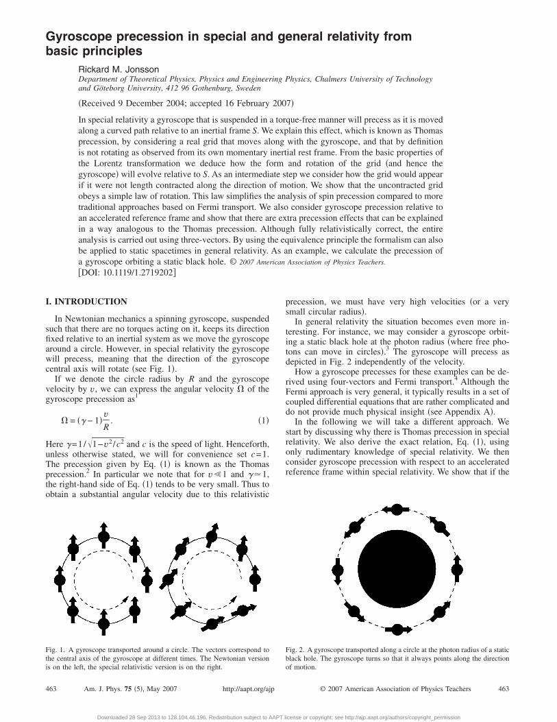
In Newtonian mechanics a spinning gyroscope, suspendedsuch that there are no torques acting on it, keeps its directionfixed relative to an inertial system as we move the gyroscopearound a circle. However, in special relativity the gyroscopewill precess, meaning that the direction of the gyroscopecentral axis will rotate �see Fig. 1�.
If we denote the circle radius by R and the gyroscopevelocity by v, we can express the angular velocity � of thegyroscope precession as1
� = �� − 1�vR
. �1�
Here �=1/�1−v2 /c2 and c is the speed of light. Henceforth,unless otherwise stated, we will for convenience set c=1.The precession given by Eq. �1� is known as the Thomasprecession.2 In particular we note that for v�1 and ��1,the right-hand side of Eq. �1� tends to be very small. Thus toobtain a substantial angular velocity due to this relativistic
Fig. 1. A gyroscope transported around a circle. The vectors correspond tothe central axis of the gyroscope at different times. The Newtonian version
is on the left, the special relativistic version is on the right.463 Am. J. Phys. 75 �5�, May 2007 http://aapt.org/ajp
Downloaded 28 Sep 2013 to 128.104.46.196. Redistribution subject to AAPT l
precession, we must have very high velocities �or a verysmall circular radius�.
In general relativity the situation becomes even more in-teresting. For instance, we may consider a gyroscope orbit-ing a static black hole at the photon radius �where free pho-tons can move in circles�.3 The gyroscope will precess asdepicted in Fig. 2 independently of the velocity.
How a gyroscope precesses for these examples can be de-rived using four-vectors and Fermi transport.4 Although theFermi approach is very general, it typically results in a set ofcoupled differential equations that are rather complicated anddo not provide much physical insight �see Appendix A�.
In the following we will take a different approach. Westart by discussing why there is Thomas precession in specialrelativity. We also derive the exact relation, Eq. �1�, usingonly rudimentary knowledge of special relativity. We thenconsider gyroscope precession with respect to an acceleratedreference frame within special relativity. We show that if the
Fig. 2. A gyroscope transported along a circle at the photon radius of a staticblack hole. The gyroscope turns so that it always points along the direction
of motion.463© 2007 American Association of Physics Teachers
icense or copyright; see http://ajp.aapt.org/authors/copyright_permission
gyroscope moves inertially, but the reference frame acceler-ates perpendicularly to the gyroscope direction of motion,the gyroscope will precess relative to the reference frame.
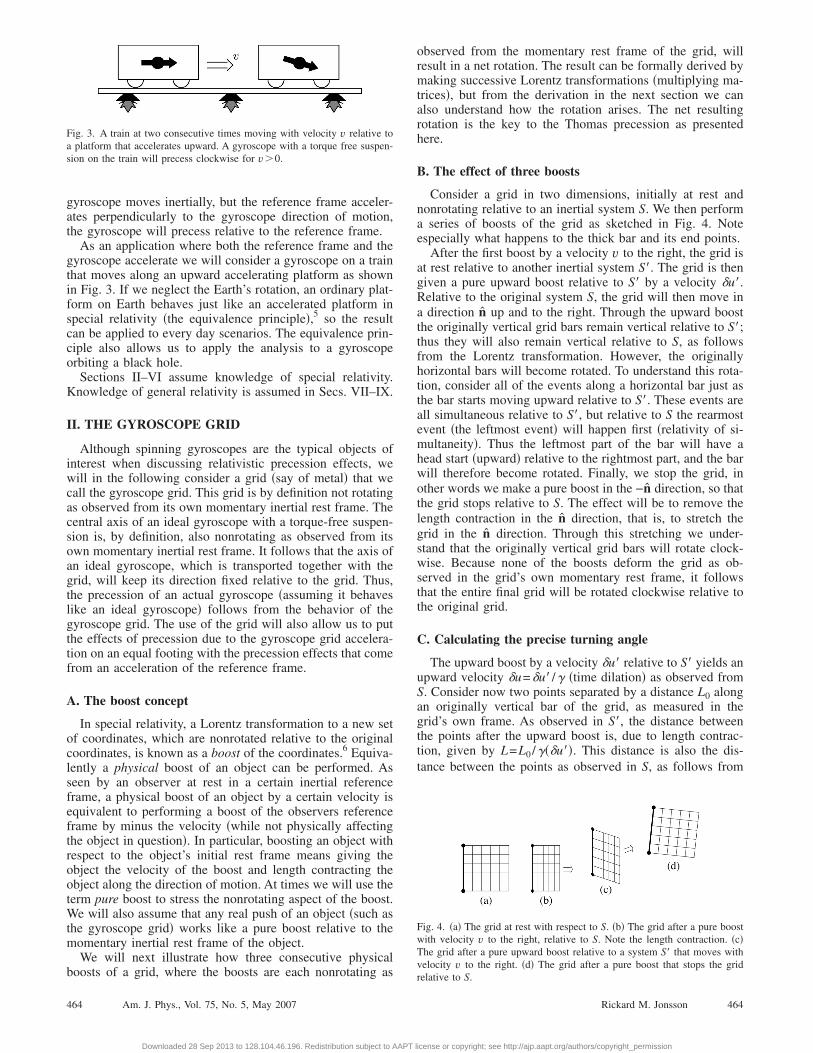
As an application where both the reference frame and thegyroscope accelerate we will consider a gyroscope on a trainthat moves along an upward accelerating platform as shownin Fig. 3. If we neglect the Earth’s rotation, an ordinary plat-form on Earth behaves just like an accelerated platform inspecial relativity �the equivalence principle�,5 so the resultcan be applied to every day scenarios. The equivalence prin-ciple also allows us to apply the analysis to a gyroscopeorbiting a black hole.
Sections II–VI assume knowledge of special relativity.Knowledge of general relativity is assumed in Secs. VII–IX.
II. THE GYROSCOPE GRID
Although spinning gyroscopes are the typical objects ofinterest when discussing relativistic precession effects, wewill in the following consider a grid �say of metal� that wecall the gyroscope grid. This grid is by definition not rotatingas observed from its own momentary inertial rest frame. Thecentral axis of an ideal gyroscope with a torque-free suspen-sion is, by definition, also nonrotating as observed from itsown momentary inertial rest frame. It follows that the axis ofan ideal gyroscope, which is transported together with thegrid, will keep its direction fixed relative to the grid. Thus,the precession of an actual gyroscope �assuming it behaveslike an ideal gyroscope� follows from the behavior of thegyroscope grid. The use of the grid will also allow us to putthe effects of precession due to the gyroscope grid accelera-tion on an equal footing with the precession effects that comefrom an acceleration of the reference frame.
A. The boost concept
In special relativity, a Lorentz transformation to a new setof coordinates, which are nonrotated relative to the originalcoordinates, is known as a boost of the coordinates.6 Equiva-lently a physical boost of an object can be performed. Asseen by an observer at rest in a certain inertial referenceframe, a physical boost of an object by a certain velocity isequivalent to performing a boost of the observers referenceframe by minus the velocity �while not physically affectingthe object in question�. In particular, boosting an object withrespect to the object’s initial rest frame means giving theobject the velocity of the boost and length contracting theobject along the direction of motion. At times we will use theterm pure boost to stress the nonrotating aspect of the boost.We will also assume that any real push of an object �such asthe gyroscope grid� works like a pure boost relative to themomentary inertial rest frame of the object.
We will next illustrate how three consecutive physical
Fig. 3. A train at two consecutive times moving with velocity v relative toa platform that accelerates upward. A gyroscope with a torque free suspen-sion on the train will precess clockwise for v�0.
boosts of a grid, where the boosts are each nonrotating as
464 Am. J. Phys., Vol. 75, No. 5, May 2007
Downloaded 28 Sep 2013 to 128.104.46.196. Redistribution subject to AAPT l
observed from the momentary rest frame of the grid, willresult in a net rotation. The result can be formally derived bymaking successive Lorentz transformations �multiplying ma-trices�, but from the derivation in the next section we canalso understand how the rotation arises. The net resultingrotation is the key to the Thomas precession as presentedhere.
B. The effect of three boosts
Consider a grid in two dimensions, initially at rest andnonrotating relative to an inertial system S. We then performa series of boosts of the grid as sketched in Fig. 4. Noteespecially what happens to the thick bar and its end points.
After the first boost by a velocity v to the right, the grid isat rest relative to another inertial system S�. The grid is thengiven a pure upward boost relative to S� by a velocity �u�.Relative to the original system S, the grid will then move ina direction n up and to the right. Through the upward boostthe originally vertical grid bars remain vertical relative to S�;thus they will also remain vertical relative to S, as followsfrom the Lorentz transformation. However, the originallyhorizontal bars will become rotated. To understand this rota-tion, consider all of the events along a horizontal bar just asthe bar starts moving upward relative to S�. These events areall simultaneous relative to S�, but relative to S the rearmostevent �the leftmost event� will happen first �relativity of si-multaneity�. Thus the leftmost part of the bar will have ahead start �upward� relative to the rightmost part, and the barwill therefore become rotated. Finally, we stop the grid, inother words we make a pure boost in the −n direction, so thatthe grid stops relative to S. The effect will be to remove thelength contraction in the n direction, that is, to stretch thegrid in the n direction. Through this stretching we under-stand that the originally vertical grid bars will rotate clock-wise. Because none of the boosts deform the grid as ob-served in the grid’s own momentary rest frame, it followsthat the entire final grid will be rotated clockwise relative tothe original grid.
C. Calculating the precise turning angle
The upward boost by a velocity �u� relative to S� yields anupward velocity �u=�u� /� �time dilation� as observed fromS. Consider now two points separated by a distance L0 alongan originally vertical bar of the grid, as measured in thegrid’s own frame. As observed in S�, the distance betweenthe points after the upward boost is, due to length contrac-tion, given by L=L0 /���u��. This distance is also the dis-tance between the points as observed in S, as follows from
Fig. 4. �a� The grid at rest with respect to S. �b� The grid after a pure boostwith velocity v to the right, relative to S. Note the length contraction. �c�The grid after a pure upward boost relative to a system S� that moves withvelocity v to the right. �d� The grid after a pure boost that stops the grid
relative to S.464Rickard M. Jonsson
icense or copyright; see http://ajp.aapt.org/authors/copyright_permission
the Lorentz transformation. Also, the velocity of the pointsafter the upward boost is vx+�uy as observed in S.
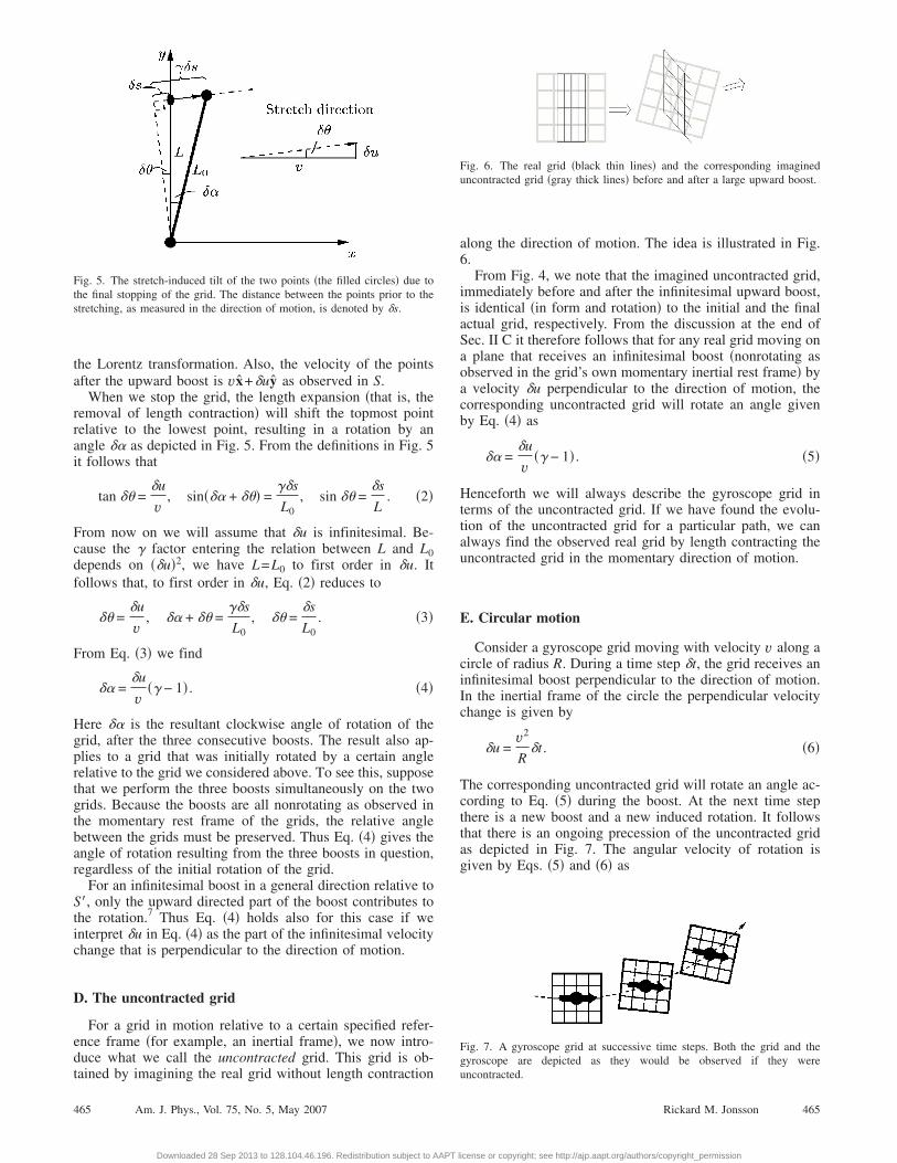
When we stop the grid, the length expansion �that is, theremoval of length contraction� will shift the topmost pointrelative to the lowest point, resulting in a rotation by anangle �� as depicted in Fig. 5. From the definitions in Fig. 5it follows that
tan �� =�u
v, sin��� + ��� =
��s
L0, sin �� =
�s
L. �2�
From now on we will assume that �u is infinitesimal. Be-cause the � factor entering the relation between L and L0depends on ��u�2, we have L=L0 to first order in �u. Itfollows that, to first order in �u, Eq. �2� reduces to
�� =�u
v, �� + �� =
��s
L0, �� =
�s
L0. �3�
From Eq. �3� we find
�� =�u
v�� − 1� . �4�
Here �� is the resultant clockwise angle of rotation of thegrid, after the three consecutive boosts. The result also ap-plies to a grid that was initially rotated by a certain anglerelative to the grid we considered above. To see this, supposethat we perform the three boosts simultaneously on the twogrids. Because the boosts are all nonrotating as observed inthe momentary rest frame of the grids, the relative anglebetween the grids must be preserved. Thus Eq. �4� gives theangle of rotation resulting from the three boosts in question,regardless of the initial rotation of the grid.
For an infinitesimal boost in a general direction relative toS�, only the upward directed part of the boost contributes tothe rotation.7 Thus Eq. �4� holds also for this case if weinterpret �u in Eq. �4� as the part of the infinitesimal velocitychange that is perpendicular to the direction of motion.
D. The uncontracted grid
For a grid in motion relative to a certain specified refer-ence frame �for example, an inertial frame�, we now intro-duce what we call the uncontracted grid. This grid is ob-
Fig. 5. The stretch-induced tilt of the two points �the filled circles� due tothe final stopping of the grid. The distance between the points prior to thestretching, as measured in the direction of motion, is denoted by �s.
tained by imagining the real grid without length contraction
465 Am. J. Phys., Vol. 75, No. 5, May 2007
Downloaded 28 Sep 2013 to 128.104.46.196. Redistribution subject to AAPT l
along the direction of motion. The idea is illustrated in Fig.6.
From Fig. 4, we note that the imagined uncontracted grid,immediately before and after the infinitesimal upward boost,is identical �in form and rotation� to the initial and the finalactual grid, respectively. From the discussion at the end ofSec. II C it therefore follows that for any real grid moving ona plane that receives an infinitesimal boost �nonrotating asobserved in the grid’s own momentary inertial rest frame� bya velocity �u perpendicular to the direction of motion, thecorresponding uncontracted grid will rotate an angle givenby Eq. �4� as
�� =�u
v�� − 1� . �5�
Henceforth we will always describe the gyroscope grid interms of the uncontracted grid. If we have found the evolu-tion of the uncontracted grid for a particular path, we canalways find the observed real grid by length contracting theuncontracted grid in the momentary direction of motion.
E. Circular motion
Consider a gyroscope grid moving with velocity v along acircle of radius R. During a time step �t, the grid receives aninfinitesimal boost perpendicular to the direction of motion.In the inertial frame of the circle the perpendicular velocitychange is given by
�u =v2
R�t . �6�
The corresponding uncontracted grid will rotate an angle ac-cording to Eq. �5� during the boost. At the next time stepthere is a new boost and a new induced rotation. It followsthat there is an ongoing precession of the uncontracted gridas depicted in Fig. 7. The angular velocity of rotation isgiven by Eqs. �5� and �6� as
Fig. 6. The real grid �black thin lines� and the corresponding imagineduncontracted grid �gray thick lines� before and after a large upward boost.
Fig. 7. A gyroscope grid at successive time steps. Both the grid and thegyroscope are depicted as they would be observed if they were
uncontracted.465Rickard M. Jonsson
icense or copyright; see http://ajp.aapt.org/authors/copyright_permission
��
�t= �� − 1�
vR
. �7�
Thus we have derived the Thomas precession given by Eq.�1�. Note that Eq. �7� describes how fast the imagined un-contracted grid rotates.
F. The mathematical advantage of the uncontracted grid
We have shown that the uncontracted grid evolves accord-ing to a simple law of rotation. The central axis of a gyro-scope, if it were not length contracted along the direction ofmotion, obeys the same simple law of rotation. The actualaxis of a gyroscope, however, changes its length over time,and its angular velocity would not be as simple as that givenby Eq. �7�. A differential equation for the evolution of theactual axis, would hide the simple dynamics of a rotation anda superimposed length contraction, which would complicatethe analysis. Similarly, the standard approach to calculatinggyroscope precession, which uses the Fermi transport equa-tion for the spin vector of the gyroscope, is also compara-tively complicated �see Appendix A and Ref. 8 for furtherdetails�.
G. Comments on the uncontracted grid
Although we may think of the uncontracted grid as amathematically convenient intermediate step in finding theactual grid, there is more to this concept. As follows from itsdefinition, the uncontracted grid corresponds directly to thegrid as experienced in a system that moves with the grid andthat is related to the reference frame in question by a pureboost.
Consider a special relativistic scenario of a gyroscope gridsuspended in a torque free manner inside a satellite. Thesatellite uses its jet engines to move along a smooth simpleclosed curve on a plane. We want to measure from the sat-ellite the precession angle of the gyroscope grid after a fullorbit. If we assume that there are a couple of suitably placedfixed stars, we can use their direction, as observed from thesatellite at the initial and final point of the orbit �which co-incide�, as guidelines to establish a reference system withinthe satellite. For this scenario the uncontracted grid is thephysical object in which we are interested, because its orien-tation precisely corresponds to the orientation of the actualgyroscope grid relative to the star calibrated reference frameof the satellite. In particular, if the uncontracted grid hasrotated a certain angle after the full orbit, so has the actualgyroscope grid as measured from the satellite.
III. BOOSTING THE REFERENCE FRAME
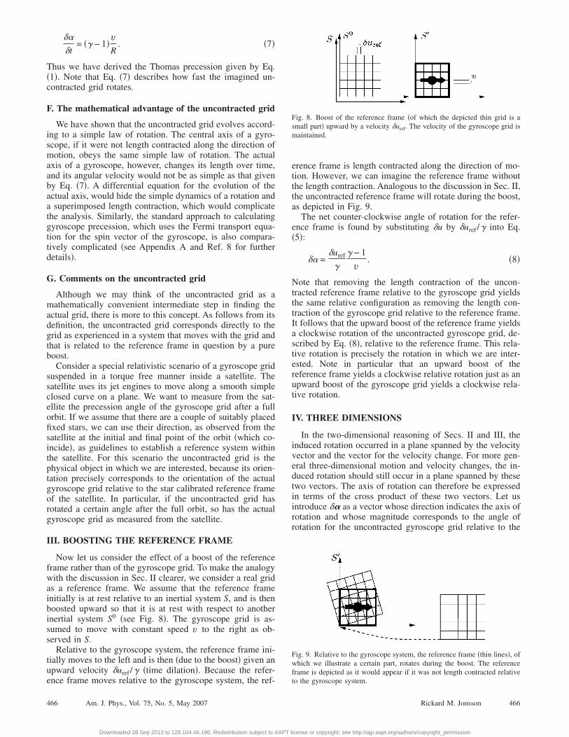
Now let us consider the effect of a boost of the referenceframe rather than of the gyroscope grid. To make the analogywith the discussion in Sec. II clearer, we consider a real gridas a reference frame. We assume that the reference frameinitially is at rest relative to an inertial system S, and is thenboosted upward so that it is at rest with respect to anotherinertial system S0 �see Fig. 8�. The gyroscope grid is as-sumed to move with constant speed v to the right as ob-served in S.
Relative to the gyroscope system, the reference frame ini-tially moves to the left and is then �due to the boost� given anupward velocity �uref /� �time dilation�. Because the refer-
ence frame moves relative to the gyroscope system, the ref-466 Am. J. Phys., Vol. 75, No. 5, May 2007
Downloaded 28 Sep 2013 to 128.104.46.196. Redistribution subject to AAPT l
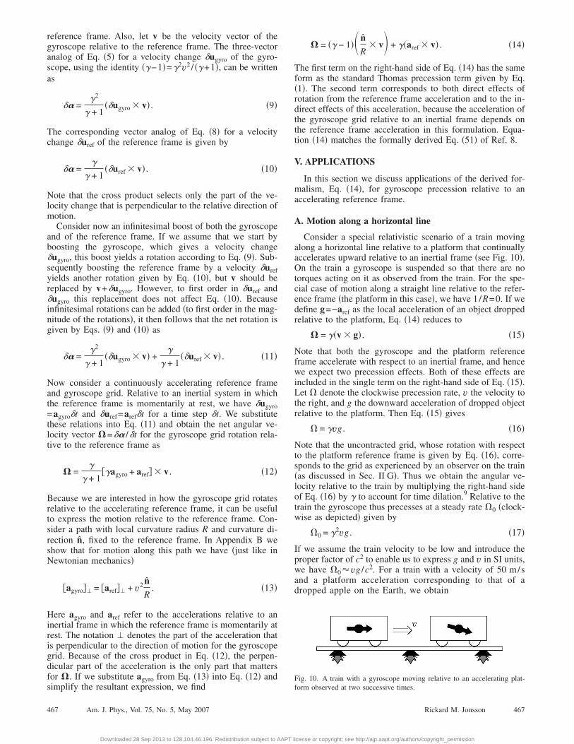
erence frame is length contracted along the direction of mo-tion. However, we can imagine the reference frame withoutthe length contraction. Analogous to the discussion in Sec. II,the uncontracted reference frame will rotate during the boost,as depicted in Fig. 9.
The net counter-clockwise angle of rotation for the refer-ence frame is found by substituting �u by �uref /� into Eq.�5�:
�� =�uref
�
� − 1
v. �8�
Note that removing the length contraction of the uncon-tracted reference frame relative to the gyroscope grid yieldsthe same relative configuration as removing the length con-traction of the gyroscope grid relative to the reference frame.It follows that the upward boost of the reference frame yieldsa clockwise rotation of the uncontracted gyroscope grid, de-scribed by Eq. �8�, relative to the reference frame. This rela-tive rotation is precisely the rotation in which we are inter-ested. Note in particular that an upward boost of thereference frame yields a clockwise relative rotation just as anupward boost of the gyroscope grid yields a clockwise rela-tive rotation.
IV. THREE DIMENSIONS
In the two-dimensional reasoning of Secs. II and III, theinduced rotation occurred in a plane spanned by the velocityvector and the vector for the velocity change. For more gen-eral three-dimensional motion and velocity changes, the in-duced rotation should still occur in a plane spanned by thesetwo vectors. The axis of rotation can therefore be expressedin terms of the cross product of these two vectors. Let usintroduce �� as a vector whose direction indicates the axis ofrotation and whose magnitude corresponds to the angle ofrotation for the uncontracted gyroscope grid relative to the
Fig. 8. Boost of the reference frame �of which the depicted thin grid is asmall part� upward by a velocity �uref. The velocity of the gyroscope grid ismaintained.
Fig. 9. Relative to the gyroscope system, the reference frame �thin lines�, ofwhich we illustrate a certain part, rotates during the boost. The referenceframe is depicted as it would appear if it was not length contracted relative
to the gyroscope system.466Rickard M. Jonsson
icense or copyright; see http://ajp.aapt.org/authors/copyright_permission
reference frame. Also, let v be the velocity vector of thegyroscope relative to the reference frame. The three-vectoranalog of Eq. �5� for a velocity change �ugyro of the gyro-scope, using the identity ��−1�=�2v2 / ��+1�, can be writtenas
�� =�2
� + 1��ugyro � v� . �9�
The corresponding vector analog of Eq. �8� for a velocitychange �uref of the reference frame is given by
�� =�
� + 1��uref � v� . �10�
Note that the cross product selects only the part of the ve-locity change that is perpendicular to the relative direction ofmotion.
Consider now an infinitesimal boost of both the gyroscopeand of the reference frame. If we assume that we start byboosting the gyroscope, which gives a velocity change�ugyro, this boost yields a rotation according to Eq. �9�. Sub-sequently boosting the reference frame by a velocity �urefyields another rotation given by Eq. �10�, but v should bereplaced by v+�ugyro. However, to first order in �uref and�ugyro this replacement does not affect Eq. �10�. Becauseinfinitesimal rotations can be added �to first order in the mag-nitude of the rotations�, it then follows that the net rotation isgiven by Eqs. �9� and �10� as
�� =�2
� + 1��ugyro � v� +
�
� + 1��uref � v� . �11�
Now consider a continuously accelerating reference frameand gyroscope grid. Relative to an inertial system in whichthe reference frame is momentarily at rest, we have �ugyro=agyro�t and �uref=aref�t for a time step �t. We substitutethese relations into Eq. �11� and obtain the net angular ve-locity vector �=�� /�t for the gyroscope grid rotation rela-tive to the reference frame as
� =�
� + 1��agyro + aref� � v . �12�
Because we are interested in how the gyroscope grid rotatesrelative to the accelerating reference frame, it can be usefulto express the motion relative to the reference frame. Con-sider a path with local curvature radius R and curvature di-rection n, fixed to the reference frame. In Appendix B weshow that for motion along this path we have �just like inNewtonian mechanics�
�agyro�� = �aref�� + v2 n
R. �13�
Here agyro and aref refer to the accelerations relative to aninertial frame in which the reference frame is momentarily atrest. The notation � denotes the part of the acceleration thatis perpendicular to the direction of motion for the gyroscopegrid. Because of the cross product in Eq. �12�, the perpen-dicular part of the acceleration is the only part that mattersfor �. If we substitute agyro from Eq. �13� into Eq. �12� and
simplify the resultant expression, we find467 Am. J. Phys., Vol. 75, No. 5, May 2007
Downloaded 28 Sep 2013 to 128.104.46.196. Redistribution subject to AAPT l
� = �� − 1�� n
R� v� + ��aref � v� . �14�
The first term on the right-hand side of Eq. �14� has the sameform as the standard Thomas precession term given by Eq.�1�. The second term corresponds to both direct effects ofrotation from the reference frame acceleration and to the in-direct effects of this acceleration, because the acceleration ofthe gyroscope grid relative to an inertial frame depends onthe reference frame acceleration in this formulation. Equa-tion �14� matches the formally derived Eq. �51� of Ref. 8.
V. APPLICATIONS
In this section we discuss applications of the derived for-malism, Eq. �14�, for gyroscope precession relative to anaccelerating reference frame.
A. Motion along a horizontal line
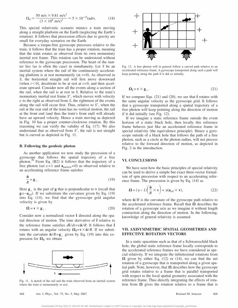
Consider a special relativistic scenario of a train movingalong a horizontal line relative to a platform that continuallyaccelerates upward relative to an inertial frame �see Fig. 10�.On the train a gyroscope is suspended so that there are notorques acting on it as observed from the train. For the spe-cial case of motion along a straight line relative to the refer-ence frame �the platform in this case�, we have 1/R=0. If wedefine g=−aref as the local acceleration of an object droppedrelative to the platform, Eq. �14� reduces to
� = ��v � g� . �15�
Note that both the gyroscope and the platform referenceframe accelerate with respect to an inertial frame, and hencewe expect two precession effects. Both of these effects areincluded in the single term on the right-hand side of Eq. �15�.Let � denote the clockwise precession rate, v the velocity tothe right, and g the downward acceleration of dropped objectrelative to the platform. Then Eq. �15� gives
� = �vg . �16�
Note that the uncontracted grid, whose rotation with respectto the platform reference frame is given by Eq. �16�, corre-sponds to the grid as experienced by an observer on the train�as discussed in Sec. II G�. Thus we obtain the angular ve-locity relative to the train by multiplying the right-hand sideof Eq. �16� by � to account for time dilation.9 Relative to thetrain the gyroscope thus precesses at a steady rate �0 �clock-wise as depicted� given by
�0 = �2vg . �17�
If we assume the train velocity to be low and introduce theproper factor of c2 to enable us to express g and v in SI units,we have �0vg /c2. For a train with a velocity of 50 m/sand a platform acceleration corresponding to that of adropped apple on the Earth, we obtain
Fig. 10. A train with a gyroscope moving relative to an accelerating plat-
form observed at two successive times.467Rickard M. Jonsson
icense or copyright; see http://ajp.aapt.org/authors/copyright_permission
�0 50 m/s � 9.81 m/s2
�3 � 108 m/s�2 5 � 10−15rad/s. �18�
This special relativistic scenario mimics a train movingalong a straight platform on the Earth �neglecting the Earth’srotation�. It follows that precession effects due to gravity aresmall for everyday scenarios on the Earth.
Because a torque-free gyroscope precesses relative to thetrain, it follows that the train has a proper rotation, meaningthat the train rotates as observed from its own momentaryinertial rest frame. This rotation can be understood withoutreference to the gyroscope precession. The heart of the mat-ter lies �as is often the case� in simultaneity. Let S be aninertial system where the rail of the continuously accelerat-ing platform is at rest momentarily �at t=0�. As observed inS, the horizontal straight rail will first move downward�when t0�, decelerate to be at rest at t=0, and then accel-erate upward. Consider now all the events along a section ofthe rail, when the rail is at rest in S. Relative to the train’smomentary inertial rest frame S�, which moves with velocityv to the right as observed from S, the rightmost of the eventsalong the rail will occur first. Thus, relative to S�, when therail at the rear end of the train has no vertical motion, the railat the front end �and thus the train’s front end� will alreadyhave an upward velocity. Hence a train moving as depictedin Fig. 10 has a proper counter-clockwise rotation. By thisreasoning we can verify the validity of Eq. �17�. We alsounderstand that as observed from S�, the rail is not straightbut is curved as depicted in Fig. 11.
B. Following the geodesic photon
As another application we now study the precession of agyroscope that follows the spatial trajectory of a freephoton.10 From Eq. �B2� it follows that the trajectory of afree photon �set v=1 and aparticle=0� as observed relative toan accelerating reference frame satisfies
n
R= g�. �19�
Here g� is the part of g that is perpendicular to v �recall thatg=−aref�. If we substitute the curvature given by Eq. �19�into Eq. �14�, we find that the gyroscope grid angularvelocity is given by
� = v � g�. �20�
Consider now a normalized vector t directed along the spa-tial direction of motion. The time derivative of t relative tothe reference frame satisfies dt /dt=vn /R. It follows that trotates with an angular velocity �t=v� n /R. If we substi-tute the curvature n /R=g� given by Eq. �19� into this ex-pression for �t, we obtain
Fig. 11. A sketch of the rail and the train observed from an inertial system
where the train is momentarily at rest.468 Am. J. Phys., Vol. 75, No. 5, May 2007
Downloaded 28 Sep 2013 to 128.104.46.196. Redistribution subject to AAPT l
�t = v � g�. �21�
If we compare Eqs. �21� and �20�, we see that t rotates withthe same angular velocity as the gyroscope grid. It followsthat a gyroscope transported along a spatial trajectory of afree photon will keep pointing along the direction of motionif it did initially �see Fig. 12�.
If we imagine a static reference frame outside the eventhorizon of a static black hole, then locally this referenceframe behaves just like an accelerated reference frame inspecial relativity �the equivalence principle�. Hence a gyro-scope outside of a black hole that follows the path of a freephoton, such as a circle at the photon radius, will not precessrelative to the forward direction of motion, as depicted inFig. 2 in the introduction.
VI. CONCLUSIONS
We have seen how the basic principles of special relativitycan be used to derive a simple but exact three-vector formal-ism of spin precession with respect to an accelerating refer-ence frame. The precession is given by Eq. �14� as
� = �� − 1�� n
R� v� + ��aref � v� , �22�
where n /R is the curvature of the gyroscope path relative tothe accelerated reference frame. Recall that � describes therotation of a gyroscope axis as we imagine it without lengthcontraction along the direction of motion. In the following,knowledge of general relativity is assumed.
VII. AXISYMMETRIC SPATIAL GEOMETRIES ANDEFFECTIVE ROTATION VECTORS
In a static spacetime such as that of a Schwarzschild blackhole, the global static reference frame locally corresponds tothe accelerated reference frames we have considered in spe-cial relativity. If we integrate the infinitesimal rotations from� given by either Eq. �12� or �14�, we can find the netrotation of a gyroscope that is transported along a given spa-tial path. Note, however, that � describes how the gyroscopegrid rotates relative to a frame that is parallel transportedwith respect to the local spatial geometry associated with thereference frame. Thus directly integrating the effects of rota-
Fig. 12. A free photon will in general follow a curved path relative to anaccelerated reference frame. A gyroscope transported along such a path willkeep pointing along the path if it did so initially.
tion from � gives the rotation relative to a frame that is
468Rickard M. Jonsson
icense or copyright; see http://ajp.aapt.org/authors/copyright_permission
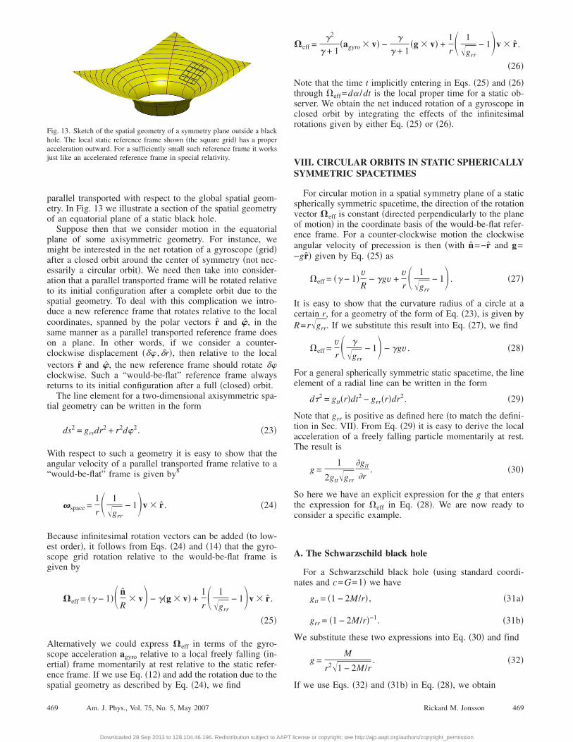
parallel transported with respect to the global spatial geom-etry. In Fig. 13 we illustrate a section of the spatial geometryof an equatorial plane of a static black hole.
Suppose then that we consider motion in the equatorialplane of some axisymmetric geometry. For instance, wemight be interested in the net rotation of a gyroscope �grid�after a closed orbit around the center of symmetry �not nec-essarily a circular orbit�. We need then take into consider-ation that a parallel transported frame will be rotated relativeto its initial configuration after a complete orbit due to thespatial geometry. To deal with this complication we intro-duce a new reference frame that rotates relative to the localcoordinates, spanned by the polar vectors r and �, in thesame manner as a parallel transported reference frame doeson a plane. In other words, if we consider a counter-clockwise displacement �� ,�r�, then relative to the localvectors r and �, the new reference frame should rotate �clockwise. Such a “would-be-flat” reference frame alwaysreturns to its initial configuration after a full �closed� orbit.
The line element for a two-dimensional axisymmetric spa-tial geometry can be written in the form
ds2 = grrdr2 + r2d2. �23�
With respect to such a geometry it is easy to show that theangular velocity of a parallel transported frame relative to a“would-be-flat” frame is given by8
�space =1
r� 1
�grr
− 1�v � r . �24�
Because infinitesimal rotation vectors can be added �to low-est order�, it follows from Eqs. �24� and �14� that the gyro-scope grid rotation relative to the would-be-flat frame isgiven by
�eff = �� − 1�� n
R� v� − ��g � v� +
1
r� 1
�grr
− 1�v � r .
�25�
Alternatively we could express �eff in terms of the gyro-scope acceleration agyro relative to a local freely falling �in-ertial� frame momentarily at rest relative to the static refer-ence frame. If we use Eq. �12� and add the rotation due to the
Fig. 13. Sketch of the spatial geometry of a symmetry plane outside a blackhole. The local static reference frame shown �the square grid� has a properacceleration outward. For a sufficiently small such reference frame it worksjust like an accelerated reference frame in special relativity.
spatial geometry as described by Eq. �24�, we find
469 Am. J. Phys., Vol. 75, No. 5, May 2007
Downloaded 28 Sep 2013 to 128.104.46.196. Redistribution subject to AAPT l
�eff =�2
� + 1�agyro � v� −
�
� + 1�g � v� +
1
r� 1
�grr
− 1�v � r .
�26�
Note that the time t implicitly entering in Eqs. �25� and �26�through �eff=d� /dt is the local proper time for a static ob-server. We obtain the net induced rotation of a gyroscope inclosed orbit by integrating the effects of the infinitesimalrotations given by either Eq. �25� or �26�.
VIII. CIRCULAR ORBITS IN STATIC SPHERICALLYSYMMETRIC SPACETIMES
For circular motion in a spatial symmetry plane of a staticspherically symmetric spacetime, the direction of the rotationvector �eff is constant �directed perpendicularly to the planeof motion� in the coordinate basis of the would-be-flat refer-ence frame. For a counter-clockwise motion the clockwiseangular velocity of precession is then �with n=−r and g=−gr� given by Eq. �25� as
�eff = �� − 1�vR
− �gv +vr� 1
�grr
− 1� . �27�
It is easy to show that the curvature radius of a circle at acertain r, for a geometry of the form of Eq. �23�, is given byR=r�grr. If we substitute this result into Eq. �27�, we find
�eff =vr� �
�grr
− 1� − �gv . �28�
For a general spherically symmetric static spacetime, the lineelement of a radial line can be written in the form
d�2 = gtt�r�dt2 − grr�r�dr2. �29�
Note that grr is positive as defined here �to match the defini-tion in Sec. VII�. From Eq. �29� it is easy to derive the localacceleration of a freely falling particle momentarily at rest.The result is
g =1
2gtt�grr
�gtt
�r. �30�
So here we have an explicit expression for the g that entersthe expression for �eff in Eq. �28�. We are now ready toconsider a specific example.
A. The Schwarzschild black hole
For a Schwarzschild black hole �using standard coordi-nates and c=G=1� we have
gtt = �1 − 2M/r� , �31a�
grr = �1 − 2M/r�−1. �31b�
We substitute these two expressions into Eq. �30� and find
g =M
r2�1 − 2M/r. �32�
If we use Eqs. �32� and �31b� in Eq. �28�, we obtain
469Rickard M. Jonsson
icense or copyright; see http://ajp.aapt.org/authors/copyright_permission
�eff =�v
r�1 − 2M/r�1 − 3M/r� −
vr
. �33�
Equation �33� gives the precession rate as a function of r andv. For constant velocity v we obtain the net rotation after afull orbit by multiplying the precession rate by the local or-bital period 2�r /v. Thus we have �per-lap=�eff2�r /v. If weuse this result together with Eq. �33�, we obtain forcounter-clockwise motion the clockwise angle of preces-sion per lap
�per-lap
2�= �
�1 − 3M/r��1 − 2M/r
− 1. �34�
In particular, for the photon radius �where geodesic photonscan move on circles� at r=3M, we obtain a rotation angle of−2� per orbit, independently of the velocity. This result isprecisely what we would expect from the discussion in Sec.V B. Equation �34� is equivalent to Eq. �39� of Ref. 11.12
B. Geodesic circular motion
For a free �geodesic� gyroscope in circular motion arounda static black hole we have, according to Eq. �13�, v2 /R=g,where R=r�grr. By also using grr given by Eq. �31b� and ggiven by Eq. �32�, we find the � factor for free circularmotion:
� =�1 − 2M/r�1 − 3M/r
. �35�
Note that � becomes infinite for r=3M as it should. If weuse Eq. �35� in Eq. �34�, we obtain
�per-lap
2�= �1 − 3M/r − 1. �36�
Equation �36� is an exact expression for the net precessionangle per full orbit for an ideal gyroscope in free circularmotion around a static black hole. If we assume the gyro-scope to be freely “floating” within a satellite, analogous tothe discussion of Sec. II G, Eq. �36� gives the rotation rela-tive to a star-calibrated reference system of the satellite.Equation �36� matches Eq. �37� of Ref. 11.
IX. RELATION TO OTHER WORK
The standard approach to calculating gyroscope preces-sion in special and general relativity is to solve the Fermiequation for the spin four-vector of the gyroscope. Even forsimple applications in special relativity, such as circular mo-tion, the resulting equations can, however, be quite compli-cated �see Appendix A�. In general relativity, the classicalapproaches to gyroscope precession are based on approxima-tions that assume “weak” gravity and small velocities �see,e.g., Refs. 4 and 13�. The derived formalisms can thereforenot be applied accurately to, for example, a gyroscope orbit-ing close to a black hole. Other approaches, such as that inRef. 11, are exact but specific to circular motion. The ap-proach of this paper, which is exact �assuming an ideal gy-roscope� and applies to arbitrary motion relative to a staticreference frame, is strongly linked to the more formal ap-
proaches in Refs. 8 and 14.470 Am. J. Phys., Vol. 75, No. 5, May 2007
Downloaded 28 Sep 2013 to 128.104.46.196. Redistribution subject to AAPT l
APPENDIX A: THE FERMI APPROACH TOCIRCULAR MOTION
In special and general relativity the spin of a gyroscope isrepresented by a four-vector S . The Fermi transport law forS is given by
DS
D�= u Du�
D�S�. �A1�
Here u is the four-velocity of the gyroscope. As a specialrelativistic application we consider motion with fixed speedv along a circle in the xy plane with an angular frequency �.We assume that the spatial part of the spin vector �Sx ,Sy ,Sz�is in the xy plane �so Sz=0� and let the gyroscope start at t=0 on the positive x axis. Solving the Fermi equation is then�effectively� reduced to solving two coupled differentialequations �see Ref. 8�:
dSx
dt= �2v2� sin ��t��Sx cos ��t� + Sy sin ��t�� , �A2a�
dSy
dt= − �2v2� cos ��t��Sx cos ��t� + Sy sin ��t�� . �A2b�
For the initial conditions �Sx ,Sy�= �S ,0� the solutions can bewritten as2
Sx = S�cos ��� − 1��t� + �� − 1� sin ���t� sin ��t�� �A3a�
Sy = S�sin ��1 − ���t� − �� − 1� sin ���t� cos ��t�� . �A3b�
The first term on the right-hand sides of Eqs. �A3a� and�A3b� corresponds to a rotation about the z axis, but there isalso another superimposed rotation with a time dependentamplitude. To find this solution directly from the coupledFermi equations seems rather difficult, even for this verysymmetric and simple scenario.
APPENDIX B: CURVATURE AND ACCELERATION
Suppose that we have an upward accelerating referenceframe. A test particle moves with velocity v along a path,fixed to the reference frame, with the local curvature R andcurvature direction n. We would like to express the part ofthe test particle’s acceleration that is perpendicular to theparticle’s momentary direction of motion, relative to an iner-tial system in which the reference frame is momentarily atrest. For this purpose, we consider how the test particle willdeviate from a straight line fixed to the inertial system anddirected in the momentary direction of motion of the testparticle.
For the small relative velocities between the inertial sys-tem and the reference frame that we will consider here, weneed not differentiate between the length and time scales ofthe two systems. Consider a short time step �t after the par-ticle has passed the origin. To lowest order with respect to �t,the perpendicular acceleration relative to the reference frameis given by v2n /R. From Fig. 14 we have to lowest nonzeroorder in �t
�x1 =n v2�t2
, �B1a�
R 2470Rickard M. Jonsson
icense or copyright; see http://ajp.aapt.org/authors/copyright_permission
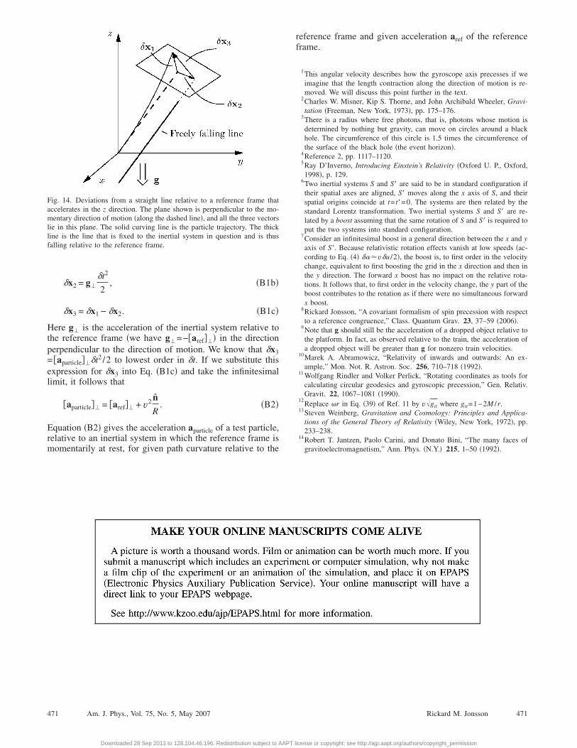
�x2 = g�
�t2
2, �B1b�
�x3 = �x1 − �x2. �B1c�
Here g� is the acceleration of the inertial system relative tothe reference frame �we have g�=−�aref��� in the directionperpendicular to the direction of motion. We know that �x3= �aparticle���t2 /2 to lowest order in �t. If we substitute thisexpression for �x3 into Eq. �B1c� and take the infinitesimallimit, it follows that
�aparticle�� = �aref�� + v2 n
R. �B2�
Equation �B2� gives the acceleration aparticle of a test particle,relative to an inertial system in which the reference frame ismomentarily at rest, for given path curvature relative to the
Fig. 14. Deviations from a straight line relative to a reference frame thataccelerates in the z direction. The plane shown is perpendicular to the mo-mentary direction of motion �along the dashed line�, and all the three vectorslie in this plane. The solid curving line is the particle trajectory. The thickline is the line that is fixed to the inertial system in question and is thusfalling relative to the reference frame.
471 Am. J. Phys., Vol. 75, No. 5, May 2007
Downloaded 28 Sep 2013 to 128.104.46.196. Redistribution subject to AAPT l
reference frame and given acceleration aref of the referenceframe.
1This angular velocity describes how the gyroscope axis precesses if weimagine that the length contraction along the direction of motion is re-moved. We will discuss this point further in the text.
2Charles W. Misner, Kip S. Thorne, and John Archibald Wheeler, Gravi-tation �Freeman, New York, 1973�, pp. 175–176.
3There is a radius where free photons, that is, photons whose motion isdetermined by nothing but gravity, can move on circles around a blackhole. The circumference of this circle is 1.5 times the circumference ofthe surface of the black hole �the event horizon�.
4Reference 2, pp. 1117–1120.5Ray D’Inverno, Introducing Einstein’s Relativity �Oxford U. P., Oxford,1998�, p. 129.
6Two inertial systems S and S� are said to be in standard configuration iftheir spatial axes are aligned, S� moves along the x axis of S, and theirspatial origins coincide at t= t�=0. The systems are then related by thestandard Lorentz transformation. Two inertial systems S and S� are re-lated by a boost assuming that the same rotation of S and S� is required toput the two systems into standard configuration.
7Consider an infinitesimal boost in a general direction between the x and yaxis of S�. Because relativistic rotation effects vanish at low speeds �ac-cording to Eq. �4� ���v�u /2�, the boost is, to first order in the velocitychange, equivalent to first boosting the grid in the x direction and then inthe y direction. The forward x boost has no impact on the relative rota-tions. It follows that, to first order in the velocity change, the y part of theboost contributes to the rotation as if there were no simultaneous forwardx boost.
8Rickard Jonsson, “A covariant formalism of spin precession with respectto a reference congruence,” Class. Quantum Grav. 23, 37–59 �2006�.
9Note that g should still be the acceleration of a dropped object relative tothe platform. In fact, as observed relative to the train, the acceleration ofa dropped object will be greater than g for nonzero train velocities.
10Marek A. Abramowicz, “Relativity of inwards and outwards: An ex-ample,” Mon. Not. R. Astron. Soc. 256, 710–718 �1992�.
11 Wolfgang Rindler and Volker Perlick, “Rotating coordinates as tools forcalculating circular geodesics and gyroscopic precession,” Gen. Relativ.Gravit. 22, 1067–1081 �1990�.
12Replace �r in Eq. �39� of Ref. 11 by v�gtt where gtt=1−2M /r.
13Steven Weinberg, Gravitation and Cosmology: Principles and Applica-tions of the General Theory of Relativity �Wiley, New York, 1972�, pp.233–238.
14Robert T. Jantzen, Paolo Carini, and Donato Bini, “The many faces of
gravitoelectromagnetism,” Ann. Phys. �N.Y.� 215, 1–50 �1992�.471Rickard M. Jonsson
icense or copyright; see http://ajp.aapt.org/authors/copyright_permission