gwc valve international - forged steel gate, globe, and check valves
DESCRIPTION
GWC produces a wide variety of ForgedSteel Gate, Globe, and Check valves. Otheravailable designs include y-pattern globeand check valves and cryogenic valves GWC produces a wide variety of ForgedSteel Gate, Globe, and Check valves. Otheravailable designs include y-pattern globeand check valves and cryogenic valvesTRANSCRIPT
GWC Valve InternationalP
ro
ve
n t
ec
hn
ol
og
y f
or
in
div
idu
al
va
lv
e s
ol
ut
ion
s –
wo
rl
dw
ide
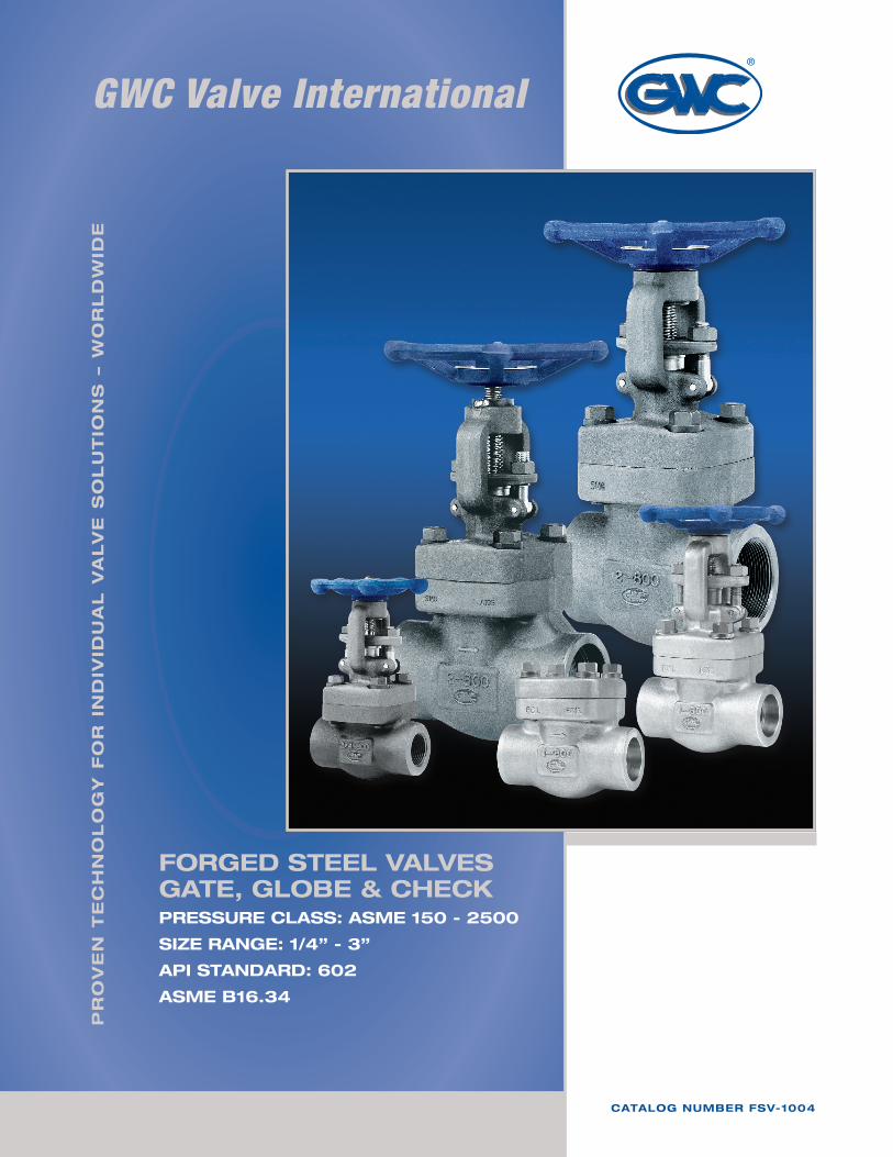
forged steel valvesgate, gloBe & checKPressure class: asMe 150 - 2500
siZe range: 1/4” - 3”
aPi standard: 602
asMe B16.34
catalog nuMBer fsv-1004

gw
c v
alv
e i
nt
er
na
tio
na
l
3
taBle of contents
Gate Vales
Standard parts and materials 5Class 800 Bolted Bonnet, Full & Reduced bore 5Class 800 Welded Bonnet, Full & Reduced bore 6Class 1500 Bolted Bonnet, Full & Reduced bore 6Class 1500 Welded Bonnet, Full & Reduced bore 7Class 2500 Pressure Seal Bonnet, Reduced bore 7Class 150/300/600/900/1500 Flanged Raised Face 8Class 2500 Flanged Raised Face 8
Ordering Guide 4
Standard parts and materials 9Class 800 Bolted Bonnet, Full & Reduced bore 9Class 800 Welded Bonnet, Full & Reduced bore 10Class 1500 Bolted Bonnet, Full & Reduced bore 10Class 1500 Welded Bonnet, Full & Reduced bore 11Class 2500 Pressure Seal Bonnet, Reduced bore 11Class 150/300/600/900/1500 Flanged Raised Face 12Class 2500 Flanged Raised Face 12Class 800 “Y” Pattern, Bolted Bonnet, Full & Reduced bore 13Class 800 “Y” Pattern, Welded Bonnet, Full & Reduced bore 13Class 1500 “Y” Pattern, Bolted Bonnet, Full & Reduced bore 14Class 1500 “Y” Pattern, Welded Bonnet, Full & Reduced bore 14
Globe ValVes
CheCk ValVes
Standard parts and materials 15Class 800 Bolted Cap, Full & Reduced bore 15Class 800 Welded Cap, Full & Reduced bore 16Class 1500 Bolted Cap, Full & Reduced bore 16Class 1500 Welded Cap, Full & Reduced bore 17Class 2500 Pressure Seal Cap, Reduced bore 17Class 150/300/600/900/1500 Flanged Raised Face 18Class 2500 Flanged Raised Face 18Class 800 “Y” Pattern, Bolted Cap, Full & Reduced bore 19Class 800 “Y” Pattern, Welded Cap, Full & Reduced bore 19Class 1500 “Y” Pattern, Bolted Cap, Full & Reduced bore 20Class 1500 “Y” Pattern, Welded Cap, Full & Reduced bore 20
Technical Data 21Pressure / Temperature Ratings 22Terms and Conditions 26Return Goods Policy 27Warranty 27
gw
c v
alv
e i
nt
er
na
tio
na
l
4
ordering guide
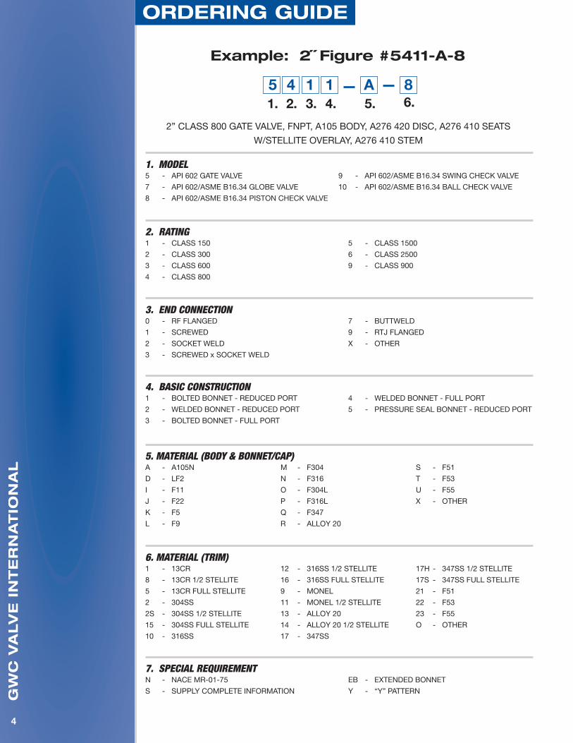
example: 2˝ figure #5411-a-8
2” CLASS 800 GATE VALVE, FNPT, A105 BODY, A276 420 DISC, A276 410 SEATS
W/STELLITE OVERLAY, A276 410 STEM
11. 2. 4. 5. 6.
153.
4 A 8
1. MODEL5 - API 602 GATE VALVE
7 - API 602/ASME B16.34 GLOBE VALVE
8 - API 602/ASME B16.34 PISTON CHECK VALVE
9 - API 602/ASME B16.34 SWING CHECK VALVE
10 - API 602/ASME B16.34 BALL CHECK VALVE
2. RATING 1 - CLASS 150
2 - CLASS 300
3 - CLASS 600
4 - CLASS 800
5 - CLASS 1500
6 - CLASS 2500
9 - CLASS 900
3. END CONNECTION0 - RF FLANGED
1 - SCREWED
2 - SOCKET WELD
3 - SCREWED x SOCKET WELD
7 - BUTTWELD
9 - RTJ FLANGED
X - OTHER
4. BASIC CONSTRUCTION1 - BOLTED BONNET - REDUCED PORT
2 - WELDED BONNET - REDUCED PORT
3 - BOLTED BONNET - FULL PORT
4 - WELDED BONNET - FULL PORT
5 - PRESSURE SEAL BONNET - REDUCED PORT
5. MATERIAL (BODY & BONNET/CAP)A - A105N
D - LF2
I - F11
J - F22
K - F5
L - F9
M - F304
N - F316
O - F304L
P - F316L
Q - F347
R - ALLOY 20
S - F51
T - F53
U - F55
X - OTHER
6. MATERIAL (TRIM)1 - 13CR
8 - 13CR 1/2 STELLITE
5 - 13CR FULL STELLITE
2 - 304SS
2S - 304SS 1/2 STELLITE
15 - 304SS FULL STELLITE
10 - 316SS
12 - 316SS 1/2 STELLITE
16 - 316SS FULL STELLITE
9 - MONEL
11 - MONEL 1/2 STELLITE
13 - ALLOY 20
14 - ALLOY 20 1/2 STELLITE
17 - 347SS
17H - 347SS 1/2 STELLITE
17S - 347SS FULL STELLITE
21 - F51
22 - F53
23 - F55
O - OTHER
7. SPECIAL REQUIREMENTN - NACE MR-01-75
S - SUPPLY COMPLETE INFORMATION
EB - EXTENDED BONNET
Y - “Y” PATTERN
gw
c v
alv
e i
nt
er
na
tio
na
l
5
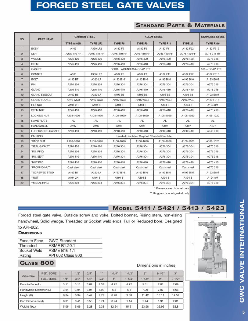
forged steel gate valves
standard Parts & Materials
NO. PART NAMECARBON STEEL ALLOY STEEL STAINLESS STEEL
TYPE A105N TYPE LF2 TYPE F5 TYPE F9 TYPE F11 TYPE 22 TYPE F316
1 BODY A105 A350 LF2 A182 F5 A182 F9 A182 F11 A182 F22 A182 F316
2 SEAT A276 410 HF A276 410 HF A276 410 HF A276 410 HF A246 410 HF A276 410 HF A276 316 HF
3 WEDGE A276 420 A276 420 A276 420 A276 420 A276 420 A276 420 A276 316
4 STEM A276 410 A276 410 A276 410 A276 410 A276 410 A276 410 A276 316
5 GASKET SPIRAL WOUND 304+GRAPHITE 316 + GRAPHITE
6 BONNET A105 A350 LF2 A182 F5 A182 F9 A182 F11 A182 F22 A182 F316
7 BOLT A193 B7 A320 L7 A193 B16 A193 B16 A193 B16 A193 B16 A193 B8M
8 PIN A276 304 A276 304 A276 304 A276 304 A276 304 A276 304 A276 316
9 GLAND A276 410 A276 410 A276 410 A276 410 A276 410 A276 410 A276 316
10 GLAND EYEBOLT A193 B8 A320 L7 A193 B8 A193 B8 A193 B8 A193 B8 A193 B8M
11 GLAND FLANGE A216 WCB A216 WCB A216 WCB A216 WCB A216 WCB A216 WCB A182 F316
12 HEX NUT A194 2H A194 8 A194 8 A194 8 A194 8 A194 8 A194 8M
13 STEM NUT A276 410 A276 410 A276 410 A276 410 A276 410 A276 410 A276 410
14 LOCKING NUT A108-1020 A108-1020 A108-1020 A108-1020 A108-1020 A108-1020 A108-1020
15 NAME PLATE AL AL AL AL AL AL AL
16 HANDWHEEL A197 A197 A197 A197 A197 A197 A197
17 LUBRICATING GASKET A240 410 A240 410 A240 410 A240 410 A240 410 A240 410 A240 410
18 PACKING Braided Graphite / Graphoil / Braided Graphite
19 *STOP NUT A108-1020 A108-1020 A108-1020 A108-1020 A108-1020 A108-1020 A108-1020
23 *SEAL GASKET A276 420 A276 420 A276 304 A276 304 A276 304 A276 304 A276 316
24 *P.S. RING A276 304 A276 304 A276 304 A276 304 A276 304 A276 304 A276 316
25 *P.S. SEAT A276 410 A276 410 A276 304 A276 304 A276 304 A276 304 A276 316
26 *NUT PAD A276 410 A276 410 A276 410 A276 410 A276 410 A276 410 A276 410
27 *PACKING NUT Cast steel Cast steel Cast steel Cast steel Cast steel Cast steel A276 316
37 **SCREWED STUD A193 B7 A320 L7 A193 B16 A193 B16 A193 B16 A193 B16 A193 B8M
38 **NUT A194 2H A194 8 A194 8 A194 8 A194 8 A194 8 A194 8M
39 **METAL RING A276 304 A276 304 A276 304 A276 304 A276 304 A276 304 A276 316
* Pressure seal bonnet only
** Ring join bonnet gasket only
diMensions
Face to Face GWC StandardThreaded ASME B1.20.1Socket Weld ASME B16.1.1Rating API 602 Class 800
Model 5411 / 5421 / 5413 / 5423Forged steel gate valve, Outside screw and yoke, Bolted bonnet, Rising stem, non-rising
handwheel, Solid wedge, Threaded or Socket weld ends, Full or Reduced bore, Designed
to API-602.
Class 800 Dimensions in inches
Valve SizeRED. BORE - 1/2” 3/4” 1” 1-1/4” 1-1/2” 2” 2-1/2” 3”
FULL BORE 1/4” 3/8” 1/2” 3/4” 1” 1-1/4” 1-1/2” 2” 2-1/2”
Face to Face (L) 3.11 3.11 3.62 4.37 4.72 4.72 5.51 7.01 7.09
Handwheel Diameter (D) 3.94 3.94 3.94 4.92 6.3 6.3 7.09 7.87 8.66
Height (H) 6.34 6.34 6.42 7.72 8.78 9.88 11.42 13.11 14.57
Port Dimension (d) 0.31 0.41 0.53 0.71 0.94 1.14 1.44 1.91 2.01
Weight (lbs.) 5.06 5.06 5.28 9.33 12.54 15.51 23.98 36.96 52.8

gw
c v
alv
e i
nt
er
na
tio
na
l
6
forged steel gate valves
Model 5412 / 5422 / 5414 / 5424
Forged steel gate valve, Outside screw and yoke, Welded bonnet, Rising stem, non-rising
handwheel, Solid wedge, Threaded or Socket weld ends, Full or Reduced bore, Designed
to API-602.
Valve SizeRED. BORE - 1/2” 3/4” 1” 1-1/4” 1-1/2” 2” 2-1/2” 3”
FULL BORE 1/4” 3/8” 1/2” 3/4” 1” 1-1/4” 1-1/2” 2” 2-1/2”
Face to Face (L) 3.11 3.11 3.62 4.37 4.72 4.72 5.51 7.01 7.09
Handwheel Diameter (D) 3.94 3.94 3.94 4.92 6.3 6.3 7.09 7.87 8.66
Height (H) 6.34 6.34 6.42 7.72 8.78 9.88 11.42 13.11 14.57
Port Dimension (d) 0.31 0.41 0.53 0.71 0.94 1.14 1.44 1.91 2.01
Weight (lbs.) 5.06 5.06 5.28 9.33 12.54 15.51 23.98 36.96 52.8
Class 800 Dimensions in inches
Face to Face GWC StandardThreaded ASME B1.20.1Socket Weld ASME B16.1.1Rating API 602 Class 800
diMensions
Valve SizeRED. BORE - 1/2” 3/4” 1” 1-1/4” 1-1/2” 2” -
FULL BORE 1/4” 3/8” 1/2” 3/4” 1” 1-1/4” 1-1/2” 2”
Face to Face (L) 3.62 4.37 4.37 4.72 4.72 5.51 7.01 7.09
Handwheel Diameter (D) 3.94 4.92 4.92 6.3 6.3 7.09 7.87 8.66
Height (H) 7.52 7.52 7.56 8.62 9.57 11.65 12.44 14.57
Port Dimension (d) 0.31 0.41 0.53 0.71 0.94 1.14 1.44 1.77
Weight (lbs.) 5.28 9.68 9.68 13.2 15.84 25.08 35.2 50.6
Class 1500 Dimensions in inches
Model 5511 / 5521 / 5513/ 5523
Forged steel gate valve, Outside screw and yoke, Bolted bonnet, Rising stem, non-rising
handwheel, Solid wedge, Threaded or Socket weld ends, Full or Reduced bore, Designed
to API-602.
diMensions
Face to Face GWC StandardThreaded ASME B1.20.1Socket Weld ASME B16.1.1Rating ASME Class 1500
gw
c v
alv
e i
nt
er
na
tio
na
l
7
forged steel gate valves
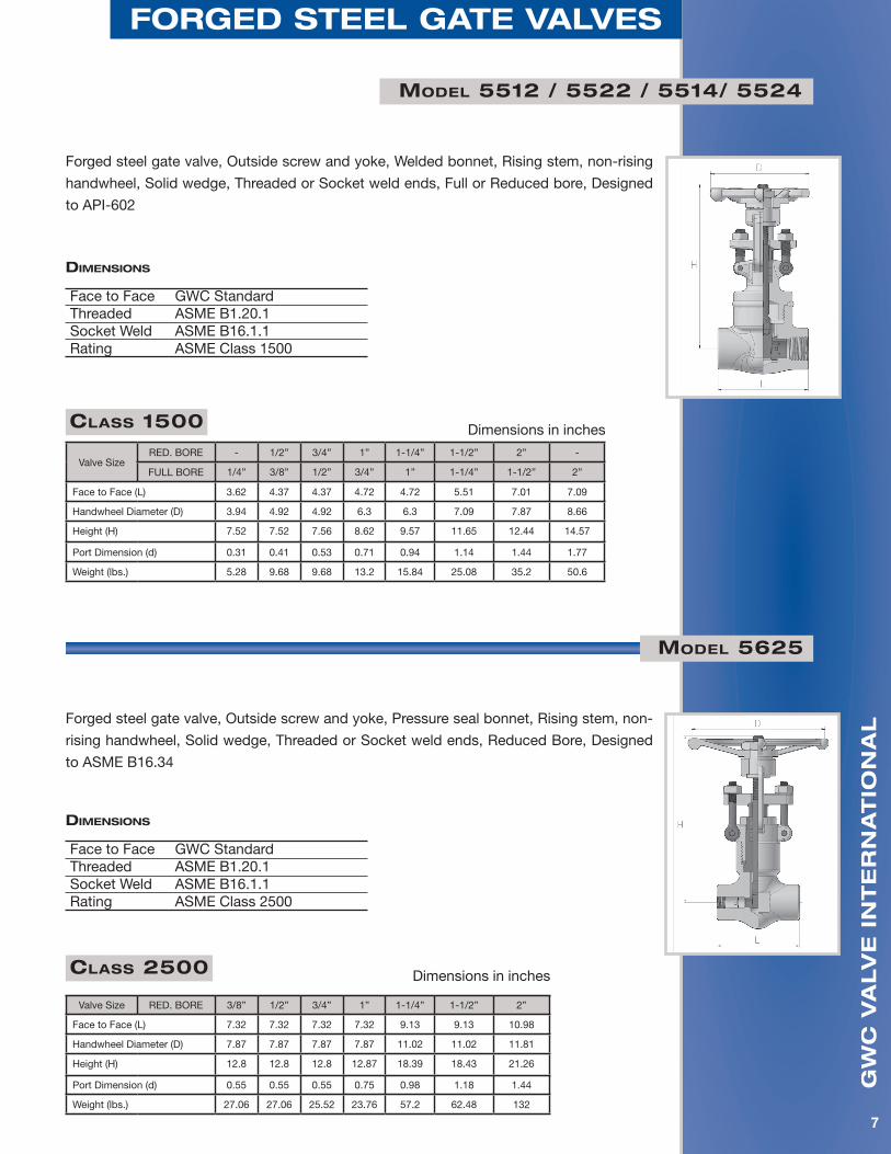
Model 5512 / 5522 / 5514/ 5524
Forged steel gate valve, Outside screw and yoke, Welded bonnet, Rising stem, non-rising
handwheel, Solid wedge, Threaded or Socket weld ends, Full or Reduced bore, Designed
to API-602
Class 1500 Dimensions in inches
Valve SizeRED. BORE - 1/2” 3/4” 1” 1-1/4” 1-1/2” 2” -
FULL BORE 1/4” 3/8” 1/2” 3/4” 1” 1-1/4” 1-1/2” 2”
Face to Face (L) 3.62 4.37 4.37 4.72 4.72 5.51 7.01 7.09
Handwheel Diameter (D) 3.94 4.92 4.92 6.3 6.3 7.09 7.87 8.66
Height (H) 7.52 7.52 7.56 8.62 9.57 11.65 12.44 14.57
Port Dimension (d) 0.31 0.41 0.53 0.71 0.94 1.14 1.44 1.77
Weight (lbs.) 5.28 9.68 9.68 13.2 15.84 25.08 35.2 50.6
diMensions
Face to Face GWC StandardThreaded ASME B1.20.1Socket Weld ASME B16.1.1Rating ASME Class 1500
Forged steel gate valve, Outside screw and yoke, Pressure seal bonnet, Rising stem, non-
rising handwheel, Solid wedge, Threaded or Socket weld ends, Reduced Bore, Designed
to ASME B16.34
Class 2500 Dimensions in inches
Valve Size RED. BORE 3/8” 1/2” 3/4” 1” 1-1/4” 1-1/2” 2”
Face to Face (L) 7.32 7.32 7.32 7.32 9.13 9.13 10.98
Handwheel Diameter (D) 7.87 7.87 7.87 7.87 11.02 11.02 11.81
Height (H) 12.8 12.8 12.8 12.87 18.39 18.43 21.26
Port Dimension (d) 0.55 0.55 0.55 0.75 0.98 1.18 1.44
Weight (lbs.) 27.06 27.06 25.52 23.76 57.2 62.48 132
diMensions
Face to Face GWC StandardThreaded ASME B1.20.1Socket Weld ASME B16.1.1Rating ASME Class 2500
Model 5625
gw
c v
alv
e i
nt
er
na
tio
na
l
8
forged steel gate valves
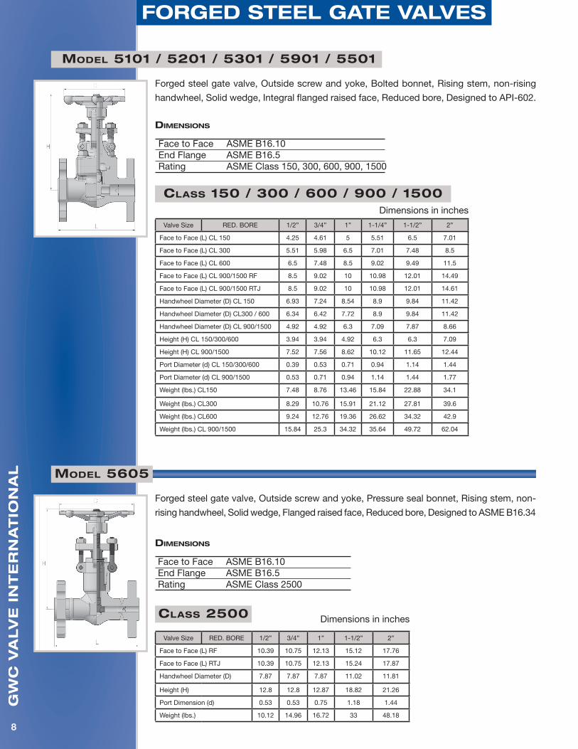
Model 5101 / 5201 / 5301 / 5901 / 5501
Forged steel gate valve, Outside screw and yoke, Bolted bonnet, Rising stem, non-rising
handwheel, Solid wedge, Integral flanged raised face, Reduced bore, Designed to API-602.
Class 150 / 300 / 600 / 900 / 1500Dimensions in inches
Valve Size RED. BORE 1/2” 3/4” 1” 1-1/4” 1-1/2” 2”
Face to Face (L) CL 150 4.25 4.61 5 5.51 6.5 7.01
Face to Face (L) CL 300 5.51 5.98 6.5 7.01 7.48 8.5
Face to Face (L) CL 600 6.5 7.48 8.5 9.02 9.49 11.5
Face to Face (L) CL 900/1500 RF 8.5 9.02 10 10.98 12.01 14.49
Face to Face (L) CL 900/1500 RTJ 8.5 9.02 10 10.98 12.01 14.61
Handwheel Diameter (D) CL 150 6.93 7.24 8.54 8.9 9.84 11.42
Handwheel Diameter (D) CL300 / 600 6.34 6.42 7.72 8.9 9.84 11.42
Handwheel Diameter (D) CL 900/1500 4.92 4.92 6.3 7.09 7.87 8.66
Height (H) CL 150/300/600 3.94 3.94 4.92 6.3 6.3 7.09
Height (H) CL 900/1500 7.52 7.56 8.62 10.12 11.65 12.44
Port Diameter (d) CL 150/300/600 0.39 0.53 0.71 0.94 1.14 1.44
Port Diameter (d) CL 900/1500 0.53 0.71 0.94 1.14 1.44 1.77
Weight (lbs.) CL150 7.48 8.76 13.46 15.84 22.88 34.1
Weight (lbs.) CL300 8.29 10.76 15.91 21.12 27.81 39.6
Weight (lbs.) CL600 9.24 12.76 19.36 26.62 34.32 42.9
Weight (lbs.) CL 900/1500 15.84 25.3 34.32 35.64 49.72 62.04
diMensions
Face to Face ASME B16.10End Flange ASME B16.5Rating ASME Class 150, 300, 600, 900, 1500
Model 5605
Forged steel gate valve, Outside screw and yoke, Pressure seal bonnet, Rising stem, non-
rising handwheel, Solid wedge, Flanged raised face, Reduced bore, Designed to ASME B16.34
Class 2500 Dimensions in inches
Valve Size RED. BORE 1/2” 3/4” 1” 1-1/2” 2”
Face to Face (L) RF 10.39 10.75 12.13 15.12 17.76
Face to Face (L) RTJ 10.39 10.75 12.13 15.24 17.87
Handwheel Diameter (D) 7.87 7.87 7.87 11.02 11.81
Height (H) 12.8 12.8 12.87 18.82 21.26
Port Dimension (d) 0.53 0.53 0.75 1.18 1.44
Weight (lbs.) 10.12 14.96 16.72 33 48.18
diMensions
Face to Face ASME B16.10End Flange ASME B16.5Rating ASME Class 2500
gw
c v
alv
e i
nt
er
na
tio
na
l
9
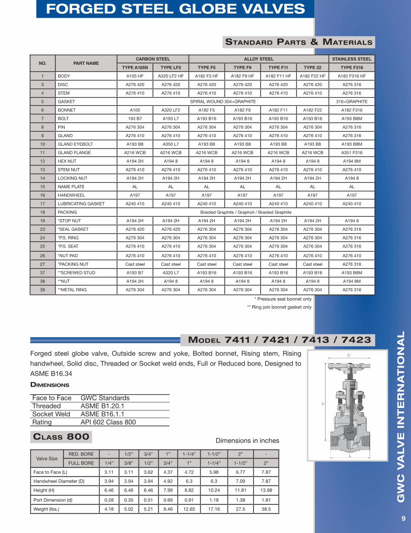
forged steel gloBe valves
standard Parts & Materials
NO. PART NAMECARBON STEEL ALLOY STEEL STAINLESS STEEL
TYPE A105N TYPE LF2 TYPE F5 TYPE F9 TYPE F11 TYPE 22 TYPE F316
1 BODY A105 HF A320 LF2 HF A182 F5 HF A182 F9 HF A182 F11 HF A182 F22 HF A182 F316 HF
3 DISC A276 420 A276 420 A276 420 A276 420 A276 420 A276 420 A276 316
4 STEM A276 410 A276 410 A276 410 A276 410 A276 410 A276 410 A276 316
5 GASKET SPIRAL WOUND 304+GRAPHITE 316+GRAPHITE
6 BONNET A105 A320 LF2 A182 F5 A182 F9 A182 F11 A182 F22 A182 F316
7 BOLT 193 B7 A193 L7 A193 B16 A193 B16 A193 B16 A193 B16 A193 B8M
8 PIN A276 304 A276 304 A276 304 A276 304 A276 304 A276 304 A276 316
9 GLAND A276 410 A276 410 A276 410 A276 410 A276 410 A276 410 A276 316
10 GLAND EYEBOLT A193 B8 A350 L7 A193 B8 A193 B8 A193 B8 A193 B8 A193 B8M
11 GLAND FLANGE A216 WCB A216 WCB A216 WCB A216 WCB A216 WCB A216 WCB A351 F316
12 HEX NUT A194 2H A194 8 A194 8 A194 8 A194 8 A194 8 A194 8M
13 STEM NUT A276 410 A276 410 A276 410 A276 410 A276 410 A276 410 A276 410
14 LOCKING NUT A194 2H A194 2H A194 2H A194 2H A194 2H A194 2H A194 8
15 NAME PLATE AL AL AL AL AL AL AL
16 HANDWHEEL A197 A197 A197 A197 A197 A197 A197
17 LUBRICATING GASKET A240 410 A240 410 A240 410 A240 410 A240 410 A240 410 A240 410
18 PACKING Braided Graphite / Graphoil / Braided Graphite
19 *STOP NUT A194 2H A194 2H A194 2H A194 2H A194 2H A194 2H A194 8
23 *SEAL GASKET A276 420 A276 420 A276 304 A276 304 A276 304 A276 304 A276 316
24 *P.S. RING A276 304 A276 304 A276 304 A276 304 A276 304 A276 304 A276 316
25 *P.S. SEAT A276 410 A276 410 A276 304 A276 304 A276 304 A276 304 A276 316
26 *NUT PAD A276 410 A276 410 A276 410 A276 410 A276 410 A276 410 A276 410
27 *PACKING NUT Cast steel Cast steel Cast steel Cast steel Cast steel Cast steel A276 316
37 **SCREWED STUD A193 B7 A320 L7 A193 B16 A193 B16 A193 B16 A193 B16 A193 B8M
38 **NUT A194 2H A194 8 A194 8 A194 8 A194 8 A194 8 A194 8M
39 **METAL RING A276 304 A276 304 A276 304 A276 304 A276 304 A276 304 A276 316
* Pressure seal bonnet only
** Ring join bonnet gasket only
Class 800 Dimensions in inches
Valve SizeRED. BORE - 1/2” 3/4” 1” 1-1/4” 1-1/2” 2” -
FULL BORE 1/4” 3/8” 1/2” 3/4” 1” 1-1/4” 1-1/2” 2”
Face to Face (L) 3.11 3.11 3.62 4.37 4.72 5.98 6.77 7.87
Handwheel Diameter (D) 3.94 3.94 3.94 4.92 6.3 6.3 7.09 7.87
Height (H) 6.46 6.46 6.46 7.99 8.82 10.24 11.81 13.98
Port Dimension (d) 0.28 0.35 0.51 0.69 0.91 1.18 1.38 1.81
Weight (lbs.) 4.18 5.02 5.21 9.46 12.65 17.16 27.5 38.5
Forged steel globe valve, Outside screw and yoke, Bolted bonnet, Rising stem, Rising
handwheel, Solid disc, Threaded or Socket weld ends, Full or Reduced bore, Designed to
ASME B16.34
diMensions
Face to Face GWC StandardsThreaded ASME B1.20.1Socket Weld ASME B16.1.1Rating API 602 Class 800
Model 7411 / 7421 / 7413 / 7423

gw
c v
alv
e i
nt
er
na
tio
na
l
10
forged steel gloBe valves
Class 800 Dimensions in inches
Valve SizeRED. BORE - 1/2” 3/4” 1” 1-1/4” 1-1/2” 2” -
FULL BORE 1/4” 3/8” 1/2” 3/4” 1” 1-1/4” 1-1/2” 2”
Face to Face (L) 3.11 3.11 3.62 4.37 4.72 5.98 6.77 7.87
Handwheel Diameter (D) 3.94 3.94 3.94 4.92 6.3 6.3 7.09 7.87
Height (H) 6.46 6.46 6.46 7.99 8.82 10.24 11.81 13.98
Port Dimension (d) 0.28 0.35 0.51 0.69 0.91 1.18 1.38 1.81
Weight (lbs.) 3.74 3.74 4.18 7.26 11.44 14.96 23.32 30.36
Forged steel globe valve, Outside screw and yoke, Welded bonnet, Rising stem, Rising
handwheel, Solid disc, Threaded or Socket weld ends, Full or Reduced bore, Designed to
ASME B16.34
Model 7412 / 7422 / 7414 / 7424
diMensions
Face to Face GWC StandardsThreaded ASME B1.20.1Socket Weld ASME B16.1.1Rating API 602 Class 800
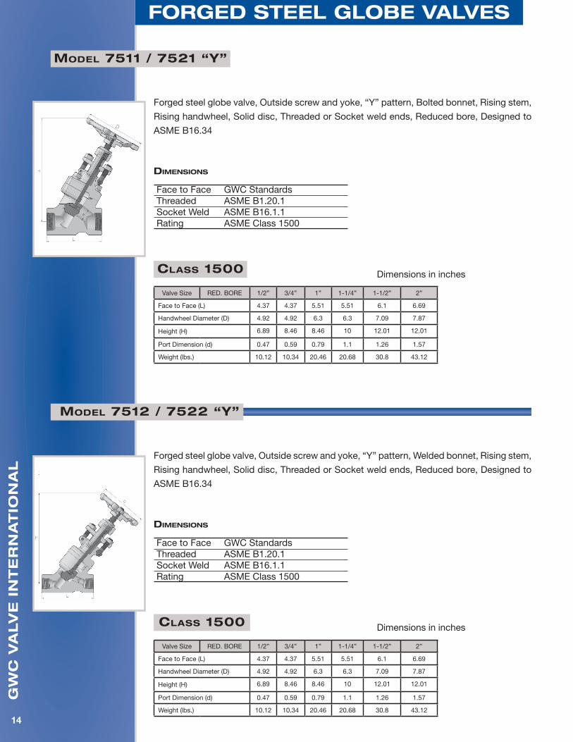
Model 7511 / 7521
Forged steel globe valve, Outside screw and yoke, Bolted bonnet, Rising stem, Rising
handwheel, Solid disc, Threaded or Socket weld ends, Reduced bore, Designed to
ASME B16.34
Class 1500 Dimensions in inches
Valve SizeRED. BORE - 1/2” 3/4” 1” 1-1/4” 1-1/2” 2” -
FULL BORE 1/4” 3/8” 1/2” 3/4” 1” 1-1/4” 1-1/2” 2”
Face to Face (L) 3.62 4.37 4.37 4.72 5.98 6.77 7.87 7.87
Handwheel Diameter (D) 3.94 4.92 4.92 6.3 6.3 7.09 7.87 9.45
Height (H) 6.73 8.15 8.15 9.45 10.16 12.99 13.98 14.57
Port Dimension (d) 0.28 0.47 0.59 0.79 1.1 1.26 1.57 1.77
Weight (lbs.) 5.06 8.14 8.58 14.96 16.72 25.52 33 48.18
diMensions
Face to Face GWC StandardsThreaded ASME B1.20.1Socket Weld ASME B16.1.1Rating ASME Class 1500
gw
c v
alv
e i
nt
er
na
tio
na
l
11
forged steel gloBe valves
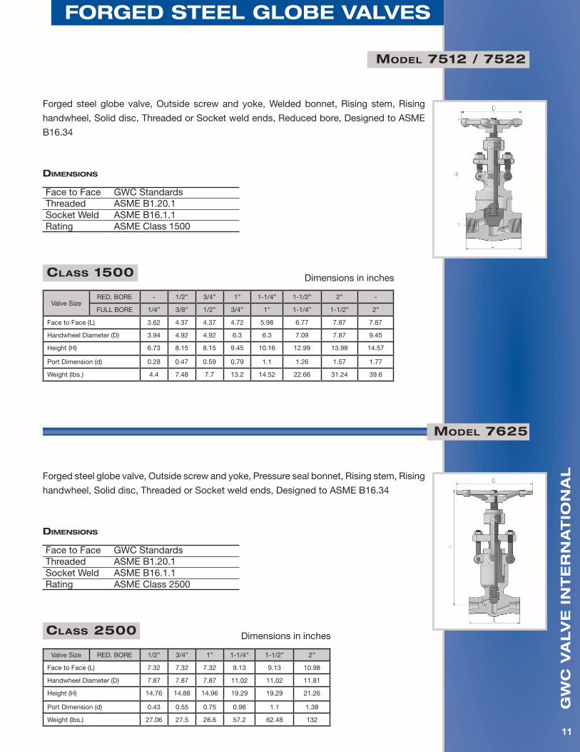
Model 7512 / 7522
Class 1500 Dimensions in inches
Valve SizeRED. BORE - 1/2” 3/4” 1” 1-1/4” 1-1/2” 2” -
FULL BORE 1/4” 3/8” 1/2” 3/4” 1” 1-1/4” 1-1/2” 2”
Face to Face (L) 3.62 4.37 4.37 4.72 5.98 6.77 7.87 7.87
Handwheel Diameter (D) 3.94 4.92 4.92 6.3 6.3 7.09 7.87 9.45
Height (H) 6.73 8.15 8.15 9.45 10.16 12.99 13.98 14.57
Port Dimension (d) 0.28 0.47 0.59 0.79 1.1 1.26 1.57 1.77
Weight (lbs.) 4.4 7.48 7.7 13.2 14.52 22.66 31.24 39.6
Forged steel globe valve, Outside screw and yoke, Welded bonnet, Rising stem, Rising
handwheel, Solid disc, Threaded or Socket weld ends, Reduced bore, Designed to ASME
B16.34
diMensions
Face to Face GWC StandardsThreaded ASME B1.20.1Socket Weld ASME B16.1.1Rating ASME Class 1500
Class 2500 Dimensions in inches
Valve Size RED. BORE 1/2” 3/4” 1” 1-1/4” 1-1/2” 2”
Face to Face (L) 7.32 7.32 7.32 9.13 9.13 10.98
Handwheel Diameter (D) 7.87 7.87 7.87 11.02 11.02 11.81
Height (H) 14.76 14.88 14.96 19.29 19.29 21.26
Port Dimension (d) 0.43 0.55 0.75 0.98 1.1 1.38
Weight (lbs.) 27.06 27.5 28.6 57.2 62.48 132
Forged steel globe valve, Outside screw and yoke, Pressure seal bonnet, Rising stem, Rising
handwheel, Solid disc, Threaded or Socket weld ends, Designed to ASME B16.34
Model 7625
diMensions
Face to Face GWC StandardsThreaded ASME B1.20.1Socket Weld ASME B16.1.1Rating ASME Class 2500
gw
c v
alv
e i
nt
er
na
tio
na
l
12
forged steel gloBe valves
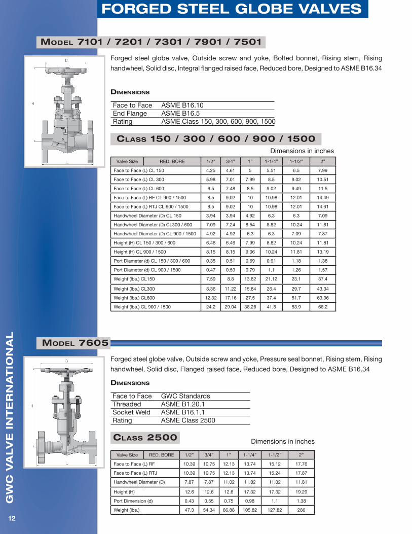
Forged steel globe valve, Outside screw and yoke, Bolted bonnet, Rising stem, Rising
handwheel, Solid disc, Integral flanged raised face, Reduced bore, Designed to ASME B16.34
Model 7101 / 7201 / 7301 / 7901 / 7501
diMensions
Face to Face ASME B16.10End Flange ASME B16.5Rating ASME Class 150, 300, 600, 900, 1500
Class 150 / 300 / 600 / 900 / 1500Dimensions in inches
Valve Size RED. BORE 1/2” 3/4” 1” 1-1/4” 1-1/2” 2”
Face to Face (L) CL 150 4.25 4.61 5 5.51 6.5 7.99
Face to Face (L) CL 300 5.98 7.01 7.99 8.5 9.02 10.51
Face to Face (L) CL 600 6.5 7.48 8.5 9.02 9.49 11.5
Face to Face (L) RF CL 900 / 1500 8.5 9.02 10 10.98 12.01 14.49
Face to Face (L) RTJ CL 900 / 1500 8.5 9.02 10 10.98 12.01 14.61
Handwheel Diameter (D) CL 150 3.94 3.94 4.92 6.3 6.3 7.09
Handwheel Diameter (D) CL300 / 600 7.09 7.24 8.54 8.82 10.24 11.81
Handwheel Diameter (D) CL 900 / 1500 4.92 4.92 6.3 6.3 7.09 7.87
Height (H) CL 150 / 300 / 600 6.46 6.46 7.99 8.82 10.24 11.81
Height (H) CL 900 / 1500 8.15 8.15 9.06 10.24 11.81 13.19
Port Diameter (d) CL 150 / 300 / 600 0.35 0.51 0.69 0.91 1.18 1.38
Port Diameter (d) CL 900 / 1500 0.47 0.59 0.79 1.1 1.26 1.57
Weight (lbs.) CL150 7.59 8.8 13.62 21.12 23.1 37.4
Weight (lbs.) CL300 8.36 11.22 15.84 26.4 29.7 43.34
Weight (lbs.) CL600 12.32 17.16 27.5 37.4 51.7 63.36
Weight (lbs.) CL 900 / 1500 24.2 29.04 38.28 41.8 53.9 68.2
Model 7605
Forged steel globe valve, Outside screw and yoke, Pressure seal bonnet, Rising stem, Rising
handwheel, Solid disc, Flanged raised face, Reduced bore, Designed to ASME B16.34
diMensions
Face to Face GWC StandardsThreaded ASME B1.20.1Socket Weld ASME B16.1.1Rating ASME Class 2500
Class 2500 Dimensions in inches
Valve Size RED. BORE 1/2” 3/4” 1” 1-1/4” 1-1/2” 2”
Face to Face (L) RF 10.39 10.75 12.13 13.74 15.12 17.76
Face to Face (L) RTJ 10.39 10.75 12.13 13.74 15.24 17.87
Handwheel Diameter (D) 7.87 7.87 11.02 11.02 11.02 11.81
Height (H) 12.6 12.6 12.6 17.32 17.32 19.29
Port Dimension (d) 0.43 0.55 0.75 0.98 1.1 1.38
Weight (lbs.) 47.3 54.34 66.88 105.82 127.82 286
gw
c v
alv
e i
nt
er
na
tio
na
l
13
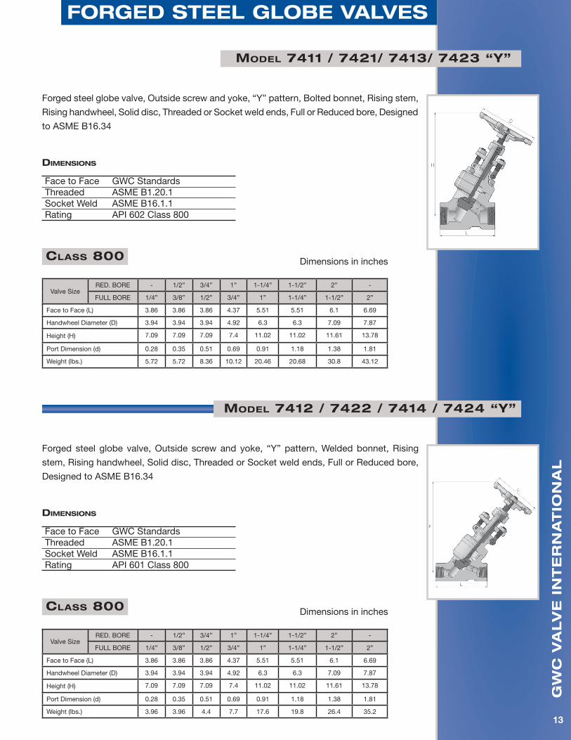
forged steel gloBe valves
Forged steel globe valve, Outside screw and yoke, “Y” pattern, Bolted bonnet, Rising stem,
Rising handwheel, Solid disc, Threaded or Socket weld ends, Full or Reduced bore, Designed
to ASME B16.34
Model 7411 / 7421/ 7413/ 7423 “Y”
diMensions
Face to Face GWC StandardsThreaded ASME B1.20.1Socket Weld ASME B16.1.1Rating API 602 Class 800
Forged steel globe valve, Outside screw and yoke, “Y” pattern, Welded bonnet, Rising
stem, Rising handwheel, Solid disc, Threaded or Socket weld ends, Full or Reduced bore,
Designed to ASME B16.34
Model 7412 / 7422 / 7414 / 7424 “Y”
diMensions
Face to Face GWC StandardsThreaded ASME B1.20.1Socket Weld ASME B16.1.1Rating API 601 Class 800
Class 800 Dimensions in inches
Valve SizeRED. BORE - 1/2” 3/4” 1” 1-1/4” 1-1/2” 2” -
FULL BORE 1/4” 3/8” 1/2” 3/4” 1” 1-1/4” 1-1/2” 2”
Face to Face (L) 3.86 3.86 3.86 4.37 5.51 5.51 6.1 6.69
Handwheel Diameter (D) 3.94 3.94 3.94 4.92 6.3 6.3 7.09 7.87
Height (H) 7.09 7.09 7.09 7.4 11.02 11.02 11.61 13.78
Port Dimension (d) 0.28 0.35 0.51 0.69 0.91 1.18 1.38 1.81
Weight (lbs.) 5.72 5.72 8.36 10.12 20.46 20.68 30.8 43.12
Class 800 Dimensions in inches
Valve SizeRED. BORE - 1/2” 3/4” 1” 1-1/4” 1-1/2” 2” -
FULL BORE 1/4” 3/8” 1/2” 3/4” 1” 1-1/4” 1-1/2” 2”
Face to Face (L) 3.86 3.86 3.86 4.37 5.51 5.51 6.1 6.69
Handwheel Diameter (D) 3.94 3.94 3.94 4.92 6.3 6.3 7.09 7.87
Height (H) 7.09 7.09 7.09 7.4 11.02 11.02 11.61 13.78
Port Dimension (d) 0.28 0.35 0.51 0.69 0.91 1.18 1.38 1.81
Weight (lbs.) 3.96 3.96 4.4 7.7 17.6 19.8 26.4 35.2
gw
c v
alv
e i
nt
er
na
tio
na
l
14
forged steel gloBe valves
Model 7512 / 7522 “Y”
Model 7511 / 7521 “Y”
Forged steel globe valve, Outside screw and yoke, “Y” pattern, Bolted bonnet, Rising stem,
Rising handwheel, Solid disc, Threaded or Socket weld ends, Reduced bore, Designed to
ASME B16.34
Forged steel globe valve, Outside screw and yoke, “Y” pattern, Welded bonnet, Rising stem,
Rising handwheel, Solid disc, Threaded or Socket weld ends, Reduced bore, Designed to
ASME B16.34
diMensions
Face to Face GWC StandardsThreaded ASME B1.20.1Socket Weld ASME B16.1.1Rating ASME Class 1500
diMensions
Face to Face GWC StandardsThreaded ASME B1.20.1Socket Weld ASME B16.1.1Rating ASME Class 1500
Class 1500 Dimensions in inches
Valve Size RED. BORE 1/2” 3/4” 1” 1-1/4” 1-1/2” 2”
Face to Face (L) 4.37 4.37 5.51 5.51 6.1 6.69
Handwheel Diameter (D) 4.92 4.92 6.3 6.3 7.09 7.87
Height (H) 6.89 8.46 8.46 10 12.01 12.01
Port Dimension (d) 0.47 0.59 0.79 1.1 1.26 1.57
Weight (lbs.) 10.12 10.34 20.46 20.68 30.8 43.12
gw
c v
alv
e i
nt
er
na
tio
na
l
15
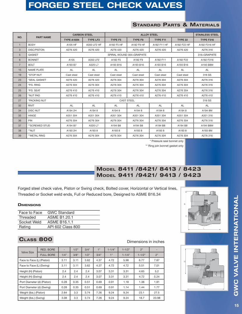
forged steel checK valves
standard Parts & Materials
NO. PART NAMECARBON STEEL ALLOY STEEL STAINLESS STEEL
TYPE A105N TYPE LF2 TYPE F5 TYPE F9 TYPE F11 TYPE 22 TYPE F316
1 BODY A105 HF A350 LF2 HF A182 F5 HF A182 F9 HF A182 F11 HF A182 F22 HF A182 F316 HF
3 DISC/PISTON A276 420 A276 420 A276 420 A276 420 A276 420 A276 420 A276 316
5 GASKET SPIRAL WOUND 304+GRAPHITE 316+GRAPHITE
6 BONNET A105 A350 LF2 A182 F5 A182 F9 A182 F11 A182 F22 A182 F316
7 BOLT A193 B7 A320 L7 A193 B16 A193 B16 A193 B16 A193 B16 A193 B8M
15 NAME PLATE AL AL AL AL AL AL AL
19 *STOP NUT Cast steel Cast steel Cast steel Cast steel Cast steel Cast steel 316 SS
23 *SEAL GASKET A276 420 A276 420 A276 304 A276 304 A276 304 A276 304 A276 316
24 *P.S. RING A276 304 A276 304 A276 304 A276 304 A276 304 A276 304 A276 316
25 *P.S. SEAT A276 410 A276 410 A276 304 A276 304 A276 304 A276 304 A276 316
26 *NUT PAD A276 410 A276 410 A276 410 A276 410 A276 410 A276 410 A276 410
27 *PACKING NUT CAST STEEL 316 SS
32 RIVIT AL AL AL AL AL AL AL
34 DISC NUT A194 2H A194 8 A194 8 A194 8 A194 8 A194 8 A194 8M
35 HINGE A351 304 A351 304 A351 304 A351 304 A351 304 A351 304 A351 316
36 PIN A276 304 A276 304 A276 304 A276 304 A276 304 A276 304 A276 316
37 **SCREWED STUD A194 B7 A320 L7 A194 B8 A194 B8 A194 B8 A194 B8 A194 B8M
38 **NUT A193 2H A193 8 A193 8 A193 8 A193 8 A193 8 A193 8M
39 **METAL RING A276 304 A276 304 A276 304 A276 304 A276 304 A276 304 A276 316
* Pressure seal bonnet only
** Ring join bonnet gasket only
Model 8411 /8421/ 8413 / 8423 Model 9411 /9421/ 9413 / 9423
Forged steel check valve, Piston or Swing check, Bolted cover, Horizontal or Vertical lines,
Threaded or Socket weld ends, Full or Reduced bore, Designed to ASME B16.34
Class 800 Dimensions in inches
Valve SizeRED. BORE - 1/2" 3/4" 1" 1-1/4" 1-1/2" 2" -
FULL BORE 1/4" 3/8" 1/2" 3/4" 1" 1-1/4" 1-1/2" 2"
Face to Face (L) (Piston) 3.11 3.11 3.62 4.37 4.72 5.98 6.77 7.87
Face to Face (L) (Swing) 3.11 3.11 3.62 4.37 4.72 4.72 5.51 7.01
Height (H) (Piston) 2.4 2.4 2.4 3.07 3.31 3.31 4.65 5.2
Height (H) (Swing) 2.4 2.4 2.4 3.07 3.31 3.31 4.72 5.24
Port Diameter (d) (Piston) 0.28 0.35 0.51 0.69 0.91 1.18 1.38 1.81
Port Diameter (d) (Swing) 0.28 0.35 0.51 0.69 0.91 1.14 1.44 1.77
Weight (lbs.) (Piston) 2.64 3.3 3.74 7.26 9.24 9.24 23.1 27.5
Weight (lbs.) (Swing) 3.08 3.3 3.74 7.26 9.24 9.24 18.7 23.98
diMensions
Face to Face GWC Standard Threaded ASME B1.20.1 Socket Weld ASME B16.1.1 Rating API 602 Class 800
gw
c v
alv
e i
nt
er
na
tio
na
l
16
forged steel checK valves
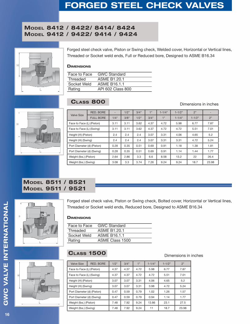
Model 8412 / 8422/ 8414/ 8424Model 9412 / 9422/ 9414 / 9424
Forged steel check valve, Piston or Swing check, Welded cover, Horizontal or Vertical lines,
Threaded or Socket weld ends, Full or Reduced bore, Designed to ASME B16.34
Class 800 Dimensions in inches
Valve SizeRED. BORE - 1/2" 3/4" 1" 1-1/4" 1-1/2" 2" -
FULL BORE 1/4" 3/8" 1/2" 3/4" 1" 1-1/4" 1-1/2" 2"
Face to Face (L) (Piston) 3.11 3.11 3.62 4.37 4.72 5.98 6.77 7.87
Face to Face (L) (Swing) 3.11 3.11 3.62 4.37 4.72 4.72 5.51 7.01
Height (H) (Piston) 2.4 2.4 2.4 3.07 3.31 4.06 4.65 5.2
Height (H) (Swing) 2.4 2.4 2.4 3.07 3.31 3.31 4.72 5.24
Port Diameter (d) (Piston) 0.28 0.35 0.51 0.69 0.91 1.18 1.38 1.81
Port Diameter (d) (Swing) 0.28 0.35 0.51 0.69 0.91 1.14 1.44 1.77
Weight (lbs.) (Piston) 2.64 2.86 3.3 6.6 8.58 13.2 22 26.4
Weight (lbs.) (Swing) 3.08 3.3 3.74 7.26 9.24 9.24 18.7 23.98
Forged steel check valve, Piston or Swing check, Bolted cover, Horizontal or Vertical lines,
Threaded or Socket weld ends, Reduced bore, Designed to ASME B16.34
Class 1500 Dimensions in inches
Valve Size RED. BORE 1/2" 3/4" 1" 1-1/4" 1-1/2" 2"
Face to Face (L) (Piston) 4.37 4.37 4.72 5.98 6.77 7.87
Face to Face (L) (Swing) 4.37 4.37 4.72 4.72 5.51 7.01
Height (H) (Piston) 3.07 3.07 3.31 4.06 4.65 5.2
Height (H) (Swing) 3.07 3.07 3.31 3.98 4.72 5.24
Port Diameter (d) (Piston) 0.47 0.59 0.79 1.02 1.26 1.57
Port Diameter (d) (Swing) 0.47 0.59 0.79 0.94 1.14 1.77
Weight (lbs.) (Piston) 7.48 7.92 9.24 13.86 23.1 27.5
Weight (lbs.) (Swing) 7.48 7.92 9.24 11 18.7 23.98
Model 8511 / 8521Model 9511 / 9521
diMensions
Face to Face GWC Standard Threaded ASME B1.20.1 Socket Weld ASME B16.1.1 Rating API 602 Class 800
diMensions
Face to Face GWC Standard Threaded ASME B1.20.1 Socket Weld ASME B16.1.1 Rating ASME Class 1500
gw
c v
alv
e i
nt
er
na
tio
na
l
17
forged steel checK valves
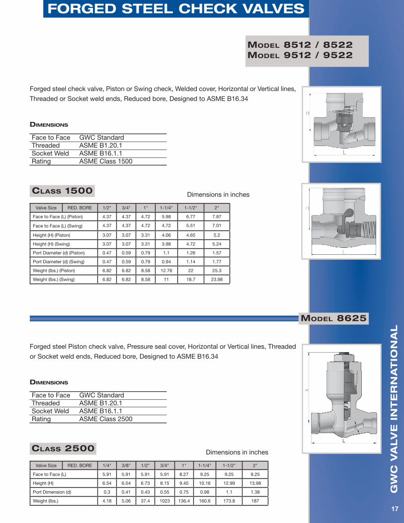
Forged steel check valve, Piston or Swing check, Welded cover, Horizontal or Vertical lines,
Threaded or Socket weld ends, Reduced bore, Designed to ASME B16.34
Class 1500 Dimensions in inches
Valve Size RED. BORE 1/2" 3/4" 1" 1-1/4" 1-1/2" 2"
Face to Face (L) (Piston) 4.37 4.37 4.72 5.98 6.77 7.87
Face to Face (L) (Swing) 4.37 4.37 4.72 4.72 5.51 7.01
Height (H) (Piston) 3.07 3.07 3.31 4.06 4.65 5.2
Height (H) (Swing) 3.07 3.07 3.31 3.98 4.72 5.24
Port Diameter (d) (Piston) 0.47 0.59 0.79 1.1 1.26 1.57
Port Diameter (d) (Swing) 0.47 0.59 0.79 0.94 1.14 1.77
Weight (lbs.) (Piston) 6.82 6.82 8.58 12.76 22 25.3
Weight (lbs.) (Swing) 6.82 6.82 8.58 11 18.7 23.98
Model 8512 / 8522Model 9512 / 9522
diMensions
Face to Face GWC Standard Threaded ASME B1.20.1 Socket Weld ASME B16.1.1 Rating ASME Class 1500
Model 8625
Forged steel Piston check valve, Pressure seal cover, Horizontal or Vertical lines, Threaded
or Socket weld ends, Reduced bore, Designed to ASME B16.34
Class 2500 Dimensions in inches
Valve Size RED. BORE 1/4" 3/8" 1/2" 3/4" 1" 1-1/4" 1-1/2" 2"
Face to Face (L) 5.91 5.91 5.91 5.91 8.27 9.25 9.25 9.25
Height (H) 6.54 6.54 6.73 8.15 9.45 10.16 12.99 13.98
Port Dimension (d) 0.3 0.41 0.43 0.55 0.75 0.98 1.1 1.38
Weight (lbs.) 4.18 5.06 37.4 1023 136.4 160.6 173.8 187
diMensions
Face to Face GWC Standard Threaded ASME B1.20.1 Socket Weld ASME B16.1.1 Rating ASME Class 2500
gw
c v
alv
e i
nt
er
na
tio
na
l
18
forged steel checK valves
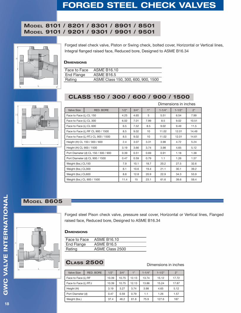
Forged steel check valve, Piston or Swing check, bolted cover, Horizontal or Vertical lines,
Integral flanged raised face, Reduced bore, Designed to ASME B16.34
Model 8101 / 8201 / 8301 / 8901 / 8501Model 9101 / 9201 / 9301 / 9901 / 9501
Class 150 / 300 / 600 / 900 / 1500Dimensions in inches
Valve Size RED. BORE 1/2" 3/4" 1" 1-1/4" 1-1/2" 2"
Face to Face (L) CL 150 4.25 4.65 5 5.51 6.54 7.99
Face to Face (L) CL 300 6.02 7.01 7.99 8.5 9.02 10.51
Face to Face (L) CL 600 6.5 7.52 8.5 9.02 9.49 11.5
Face to Face (L) RF CL 900 / 1500 8.5 9.02 10 11.02 12.01 14.49
Face to Face (L) RTJ CL 900 / 1500 8.5 9.02 10 11.02 12.01 14.61
Height (H) CL 150 / 300 / 600 2.4 3.07 3.31 3.98 4.72 5.24
Height (H) CL 900 / 1500 3.19 3.66 3.74 3.98 4.65 5.12
Port Diameter (d) CL 150 / 300 / 900 0.39 0.51 0.69 0.91 1.18 1.38
Port Diameter (d) CL 900 / 1500 0.47 0.59 0.79 1.1 1.26 1.57
Weight (lbs.) CL150 7.9 10.1 18.7 20.2 27.5 32.6
Weight (lbs.) CL300 8.1 10.6 19.4 21.1 30.1 39.2
Weight (lbs.) CL600 8.8 12.8 20.9 22.9 34.3 53.9
Weight (lbs.) CL 900 / 1500 11.4 15 23.1 61.6 39.6 59.4
Forged steel Pison check valve, pressure seal cover, Horizontal or Vertical lines, Flanged
raised face, Reduced bore, Designed to ASME B16.34
Model 8605
diMensions
Face to Face ASME B16.10 End Flange ASME B16.5 Rating ASME Class 2500
Class 2500 Dimensions in inches
Valve Size RED. BORE 1/2" 3/4" 1" 1-1/4" 1-1/2" 2"
Face to Face (L) RF 10.39 10.75 12.13 13.74 15.12 17.72
Face to Face (L) RTJ 10.39 10.75 12.13 13.86 15.24 17.87
Height (H) 3.19 3.27 3.74 3.98 4.65 5.12
Port Diameter (d) 0.47 0.59 0.79 1.1 1.26 1.57
Weight (lbs.) 37.4 46.2 61.6 75.9 127.6 187
diMensions
Face to Face ASME B16.10End Flange ASME B16.5 Rating ASME Class 150, 300, 600, 900, 1500
gw
c v
alv
e i
nt
er
na
tio
na
l
19
forged steel checK valves
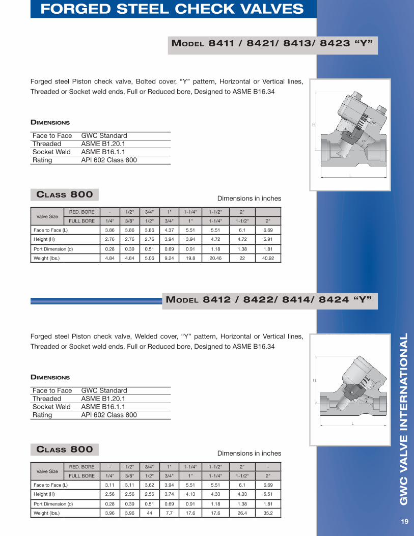
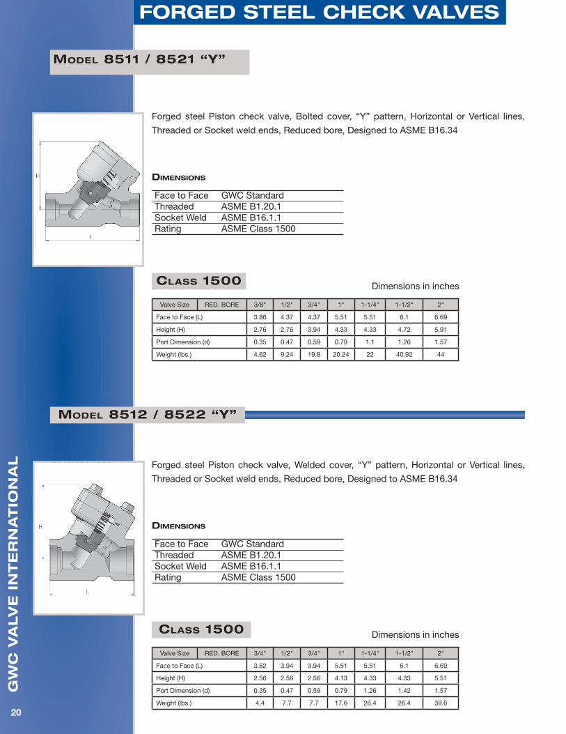
Forged steel Piston check valve, Bolted cover, “Y” pattern, Horizontal or Vertical lines,
Threaded or Socket weld ends, Full or Reduced bore, Designed to ASME B16.34
Valve SizeRED. BORE - 1/2" 3/4" 1" 1-1/4" 1-1/2" 2"
FULL BORE 1/4" 3/8" 1/2" 3/4" 1" 1-1/4" 1-1/2" 2"
Face to Face (L) 3.86 3.86 3.86 4.37 5.51 5.51 6.1 6.69
Height (H) 2.76 2.76 2.76 3.94 3.94 4.72 4.72 5.91
Port Dimension (d) 0.28 0.39 0.51 0.69 0.91 1.18 1.38 1.81
Weight (lbs.) 4.84 4.84 5.06 9.24 19.8 20.46 22 40.92
Class 800 Dimensions in inches
Forged steel Piston check valve, Welded cover, “Y” pattern, Horizontal or Vertical lines,
Threaded or Socket weld ends, Full or Reduced bore, Designed to ASME B16.34
Model 8412 / 8422/ 8414/ 8424 “Y”
Model 8411 / 8421/ 8413/ 8423 “Y”
Valve SizeRED. BORE - 1/2" 3/4" 1" 1-1/4" 1-1/2" 2" -
FULL BORE 1/4" 3/8" 1/2" 3/4" 1" 1-1/4" 1-1/2" 2"
Face to Face (L) 3.11 3.11 3.62 3.94 5.51 5.51 6.1 6.69
Height (H) 2.56 2.56 2.56 3.74 4.13 4.33 4.33 5.51
Port Dimension (d) 0.28 0.39 0.51 0.69 0.91 1.18 1.38 1.81
Weight (lbs.) 3.96 3.96 44 7.7 17.6 17.6 26.4 35.2
Class 800 Dimensions in inches
diMensions
Face to Face GWC StandardThreaded ASME B1.20.1Socket Weld ASME B16.1.1Rating API 602 Class 800
diMensions
Face to Face GWC StandardThreaded ASME B1.20.1Socket Weld ASME B16.1.1Rating API 602 Class 800
gw
c v
alv
e i
nt
er
na
tio
na
l
20
forged steel checK valves
Forged steel Piston check valve, Bolted cover, “Y” pattern, Horizontal or Vertical lines,
Threaded or Socket weld ends, Reduced bore, Designed to ASME B16.34
Model 8511 / 8521 “Y”
Forged steel Piston check valve, Welded cover, “Y” pattern, Horizontal or Vertical lines,
Threaded or Socket weld ends, Reduced bore, Designed to ASME B16.34
Model 8512 / 8522 “Y”
Class 1500 Dimensions in inches
Valve Size RED. BORE 3/8" 1/2" 3/4" 1" 1-1/4" 1-1/2" 2"
Face to Face (L) 3.86 4.37 4.37 5.51 5.51 6.1 6.69
Height (H) 2.76 2.76 3.94 4.33 4.33 4.72 5.91
Port Dimension (d) 0.35 0.47 0.59 0.79 1.1 1.26 1.57
Weight (lbs.) 4.62 9.24 19.8 20.24 22 40.92 44
Class 1500 Dimensions in inches
Valve Size RED. BORE 3/4" 1/2" 3/4" 1" 1-1/4" 1-1/2" 2"
Face to Face (L) 3.62 3.94 3.94 5.51 5.51 6.1 6.69
Height (H) 2.56 2.56 2.56 4.13 4.33 4.33 5.51
Port Dimension (d) 0.35 0.47 0.59 0.79 1.26 1.42 1.57
Weight (lbs.) 4.4 7.7 7.7 17.6 26.4 26.4 39.6
diMensions
Face to Face GWC StandardThreaded ASME B1.20.1Socket Weld ASME B16.1.1Rating ASME Class 1500
diMensions
Face to Face GWC StandardThreaded ASME B1.20.1Socket Weld ASME B16.1.1Rating ASME Class 1500
gw
c v
alv
e i
nt
er
na
tio
na
l
21
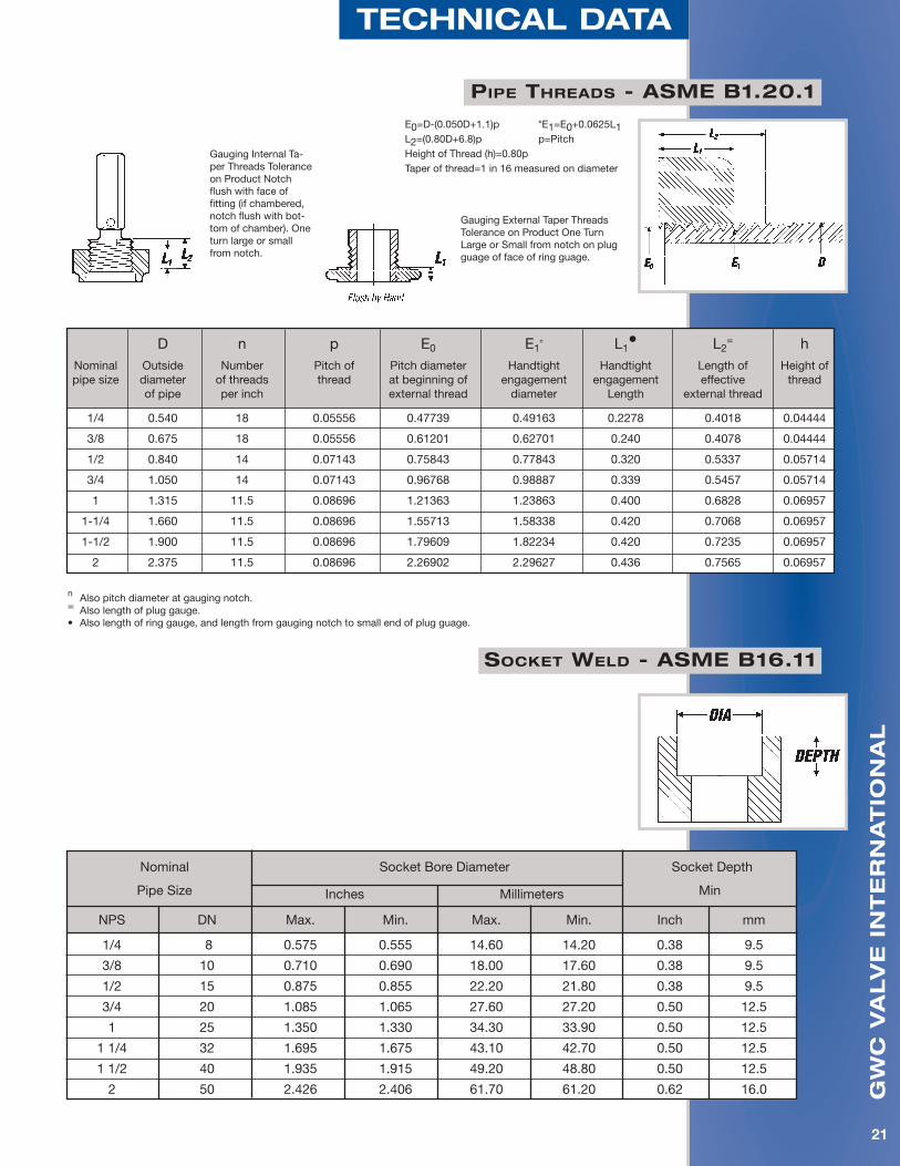
technical data
PiPe threads - asMe b1.20.1
soCket Weld - asMe b16.11
E0=D-(0.050D+1.1)p *E1=E0+0.0625L1 L2=(0.80D+6.8)p p=Pitch Height of Thread (h)=0.80p Taper of thread=1 in 16 measured on diameter
Gauging External Taper Threads Tolerance on Product One Turn Large or Small from notch on plug guage of face of ring guage.
Gauging Internal Ta-per Threads Tolerance on Product Notch flush with face of fitting (if chambered, notch flush with bot-tom of chamber). One turn large or small from notch.
n Also pitch diameter at gauging notch.= Also length of plug gauge.• Also length of ring gauge, and length from gauging notch to small end of plug guage.
D n p E0 E1n L1
• L2= h
Nominal Outside Number Pitch of Pitch diameter Handtight Handtight Length of Height of pipe size diameter of threads thread at beginning of engagement engagement effective thread of pipe per inch external thread diameter Length external thread
1/4 0.540 18 0.05556 0.47739 0.49163 0.2278 0.4018 0.04444
3/8 0.675 18 0.05556 0.61201 0.62701 0.240 0.4078 0.04444
1/2 0.840 14 0.07143 0.75843 0.77843 0.320 0.5337 0.05714
3/4 1.050 14 0.07143 0.96768 0.98887 0.339 0.5457 0.05714
1 1.315 11.5 0.08696 1.21363 1.23863 0.400 0.6828 0.06957
1-1/4 1.660 11.5 0.08696 1.55713 1.58338 0.420 0.7068 0.06957
1-1/2 1.900 11.5 0.08696 1.79609 1.82234 0.420 0.7235 0.06957
2 2.375 11.5 0.08696 2.26902 2.29627 0.436 0.7565 0.06957
Nominal Socket Bore Diameter Socket Depth
Pipe Size Inches Millimeters Min
NPS DN Max. Min. Max. Min. Inch mm
1/4 8 0.575 0.555 14.60 14.20 0.38 9.5
3/8 10 0.710 0.690 18.00 17.60 0.38 9.5
1/2 15 0.875 0.855 22.20 21.80 0.38 9.5
3/4 20 1.085 1.065 27.60 27.20 0.50 12.5
1 25 1.350 1.330 34.30 33.90 0.50 12.5
1 1/4 32 1.695 1.675 43.10 42.70 0.50 12.5
1 1/2 40 1.935 1.915 49.20 48.80 0.50 12.5
2 50 2.426 2.406 61.70 61.20 0.62 16.0

gw
c v
alv
e i
nt
er
na
tio
na
l
22
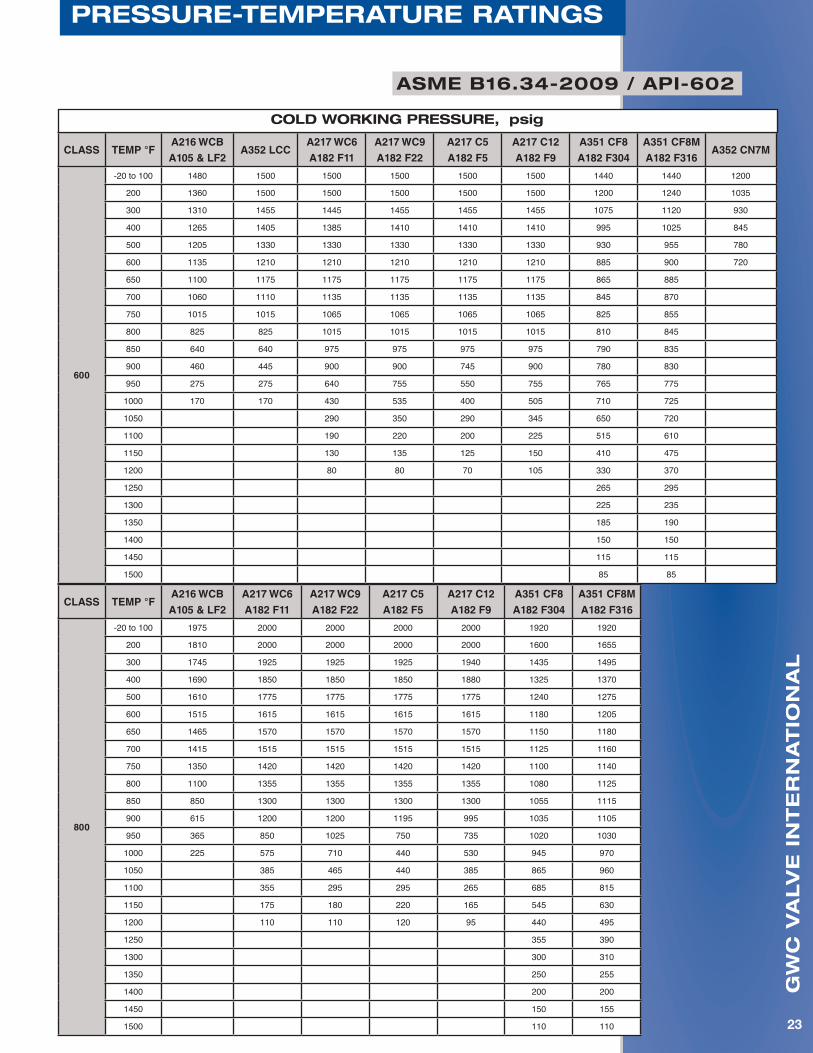
Pressure-teMPerature ratings
asMe b16.34-2009 / aPi-602
CLASS TEMP °FA216 WCB
A105 & LF2A352 LCC
A217 WC6
A182 F11
A217 WC9
A182 F22
A217 C5
A182 F5
A217 C12
A182 F9
A351 CF8
A182 F304
A351 CF8M
A182 F316A352 CN7M
150
-20 to 100 285 290 290 290 290 290 275 275 230
200 260 260 260 260 260 260 230 230 200
300 230 230 230 230 230 230 205 205 180
400 200 200 200 200 200 200 190 190 160
500 170 170 170 170 170 170 170 170 150
600 140 140 140 140 140 140 140 140 140
650 125 125 125 125 125 125 125 125
700 110 110 110 110 110 110 110 110
750 95 95 95 95 95 95 95 95
800 80 80 80 80 80 80 80 80
850 65 65 65 65 65 65 65 65
900 50 50 50 50 50 50 50 50
950 35 35 35 35 35 35 35 35
1000 20 20 20 20 20 20 20 20
1050 20 (a) 20 (a) 20 (a) 20 (a) 20(a) 20(a)
1100 20 (a) 20 (a) 20 (a) 20 (a) 20(a) 20(a)
1150 20 (a) 20 (a) 20 (a) 20 (a) 20(a) 20(a)
1200 15 (a) 15 (a) 15 (a) 20 (a) 20(a) 20(a)
1250 20(a) 20(a)
1300 20(a) 20(a)
1350 20(a) 20(a)
1400 20(a) 20(a)
1450 20(a) 20(a)
1500 15(a) 15(a)
cold worKing Pressure, psig
CLASS TEMP °FA216 WCB
A105 & LF2A352 LCC
A217 WC6
A182 F11
A217 WC9
A182 F22
A217 C5
A182 F5
A217 C12
A182 F9
A351 CF8
A182 F304
A351 CF8M
A182 F316A352 CN7M
300
-20 to 100 740 750 750 750 750 750 720 720 600
200 680 750 750 750 750 750 600 620 520
300 655 730 720 730 730 730 540 560 465
400 635 705 695 705 705 705 495 515 420
500 605 665 665 665 665 665 465 480 390
600 570 605 605 605 605 605 440 450 360
650 550 590 590 590 590 590 430 440
700 530 555 570 570 570 570 420 435
750 505 505 530 530 530 530 415 425
800 410 410 510 510 510 510 405 420
850 320 320 485 485 485 485 395 420
900 230 225 450 450 375 450 390 415
950 135 135 320 385 275 375 380 385
1000 85 85 215 265 200 255 355 365
1050 145 175 145 170 325 360
1100 95 110 100 115 255 305
1150 65 70 60 75 205 235
1200 40 40 35 50 165 185
1250 135 145
1300 115 115
1350 95 95
1400 75 75
1450 60 60
1500 40 40
(a) – Permissible, but not recommended for prolonged usage
gw
c v
alv
e i
nt
er
na
tio
na
l
23
Pressure-teMPerature ratings
CLASS TEMP °FA216 WCB
A105 & LF2A352 LCC
A217 WC6
A182 F11
A217 WC9
A182 F22
A217 C5
A182 F5
A217 C12
A182 F9
A351 CF8
A182 F304
A351 CF8M
A182 F316A352 CN7M
600
-20 to 100 1480 1500 1500 1500 1500 1500 1440 1440 1200
200 1360 1500 1500 1500 1500 1500 1200 1240 1035
300 1310 1455 1445 1455 1455 1455 1075 1120 930
400 1265 1405 1385 1410 1410 1410 995 1025 845
500 1205 1330 1330 1330 1330 1330 930 955 780
600 1135 1210 1210 1210 1210 1210 885 900 720
650 1100 1175 1175 1175 1175 1175 865 885
700 1060 1110 1135 1135 1135 1135 845 870
750 1015 1015 1065 1065 1065 1065 825 855
800 825 825 1015 1015 1015 1015 810 845
850 640 640 975 975 975 975 790 835
900 460 445 900 900 745 900 780 830
950 275 275 640 755 550 755 765 775
1000 170 170 430 535 400 505 710 725
1050 290 350 290 345 650 720
1100 190 220 200 225 515 610
1150 130 135 125 150 410 475
1200 80 80 70 105 330 370
1250 265 295
1300 225 235
1350 185 190
1400 150 150
1450 115 115
1500 85 85
cold worKing Pressure, psig
CLASS TEMP °FA216 WCB
A105 & LF2
A217 WC6
A182 F11
A217 WC9
A182 F22
A217 C5
A182 F5
A217 C12
A182 F9
A351 CF8
A182 F304
A351 CF8M
A182 F316
800
-20 to 100 1975 2000 2000 2000 2000 1920 1920
200 1810 2000 2000 2000 2000 1600 1655
300 1745 1925 1925 1925 1940 1435 1495
400 1690 1850 1850 1850 1880 1325 1370
500 1610 1775 1775 1775 1775 1240 1275
600 1515 1615 1615 1615 1615 1180 1205
650 1465 1570 1570 1570 1570 1150 1180
700 1415 1515 1515 1515 1515 1125 1160
750 1350 1420 1420 1420 1420 1100 1140
800 1100 1355 1355 1355 1355 1080 1125
850 850 1300 1300 1300 1300 1055 1115
900 615 1200 1200 1195 995 1035 1105
950 365 850 1025 750 735 1020 1030
1000 225 575 710 440 530 945 970
1050 385 465 440 385 865 960
1100 355 295 295 265 685 815
1150 175 180 220 165 545 630
1200 110 110 120 95 440 495
1250 355 390
1300 300 310
1350 250 255
1400 200 200
1450 150 155
1500 110 110
asMe b16.34-2009 / aPi-602
gw
c v
alv
e i
nt
er
na
tio
na
l
24
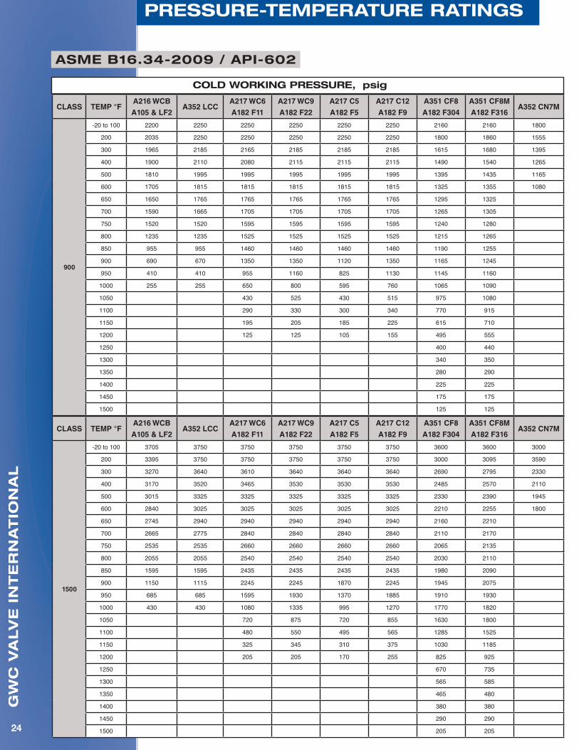
Pressure-teMPerature ratings
asMe b16.34-2009 / aPi-602
cold worKing Pressure, psig
CLASS TEMP °FA216 WCB
A105 & LF2A352 LCC
A217 WC6
A182 F11
A217 WC9
A182 F22
A217 C5
A182 F5
A217 C12
A182 F9
A351 CF8
A182 F304
A351 CF8M
A182 F316A352 CN7M
1500
-20 to 100 3705 3750 3750 3750 3750 3750 3600 3600 3000
200 3395 3750 3750 3750 3750 3750 3000 3095 3590
300 3270 3640 3610 3640 3640 3640 2690 2795 2330
400 3170 3520 3465 3530 3530 3530 2485 2570 2110
500 3015 3325 3325 3325 3325 3325 2330 2390 1945
600 2840 3025 3025 3025 3025 3025 2210 2255 1800
650 2745 2940 2940 2940 2940 2940 2160 2210
700 2665 2775 2840 2840 2840 2840 2110 2170
750 2535 2535 2660 2660 2660 2660 2065 2135
800 2055 2055 2540 2540 2540 2540 2030 2110
850 1595 1595 2435 2435 2435 2435 1980 2090
900 1150 1115 2245 2245 1870 2245 1945 2075
950 685 685 1595 1930 1370 1885 1910 1930
1000 430 430 1080 1335 995 1270 1770 1820
1050 720 875 720 855 1630 1800
1100 480 550 495 565 1285 1525
1150 325 345 310 375 1030 1185
1200 205 205 170 255 825 925
1250 670 735
1300 565 585
1350 465 480
1400 380 380
1450 290 290
1500 205 205
CLASS TEMP °FA216 WCB
A105 & LF2A352 LCC
A217 WC6
A182 F11
A217 WC9
A182 F22
A217 C5
A182 F5
A217 C12
A182 F9
A351 CF8
A182 F304
A351 CF8M
A182 F316A352 CN7M
900
-20 to 100 2200 2250 2250 2250 2250 2250 2160 2160 1800
200 2035 2250 2250 2250 2250 2250 1800 1860 1555
300 1965 2185 2165 2185 2185 2185 1615 1680 1395
400 1900 2110 2080 2115 2115 2115 1490 1540 1265
500 1810 1995 1995 1995 1995 1995 1395 1435 1165
600 1705 1815 1815 1815 1815 1815 1325 1355 1080
650 1650 1765 1765 1765 1765 1765 1295 1325
700 1590 1665 1705 1705 1705 1705 1265 1305
750 1520 1520 1595 1595 1595 1595 1240 1280
800 1235 1235 1525 1525 1525 1525 1215 1265
850 955 955 1460 1460 1460 1460 1190 1255
900 690 670 1350 1350 1120 1350 1165 1245
950 410 410 955 1160 825 1130 1145 1160
1000 255 255 650 800 595 760 1065 1090
1050 430 525 430 515 975 1080
1100 290 330 300 340 770 915
1150 195 205 185 225 615 710
1200 125 125 105 155 495 555
1250 400 440
1300 340 350
1350 280 290
1400 225 225
1450 175 175
1500 125 125
gw
c v
alv
e i
nt
er
na
tio
na
l
25
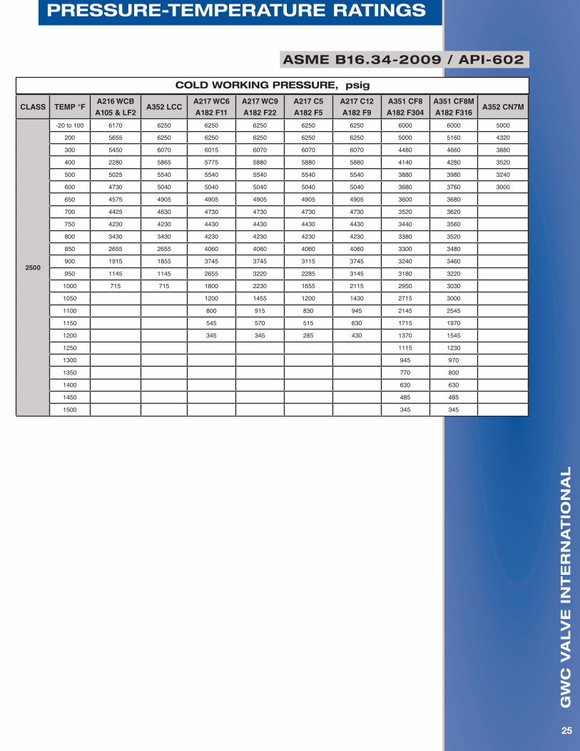
Pressure-teMPerature ratings
CLASS TEMP °FA216 WCB
A105 & LF2A352 LCC
A217 WC6
A182 F11
A217 WC9
A182 F22
A217 C5
A182 F5
A217 C12
A182 F9
A351 CF8
A182 F304
A351 CF8M
A182 F316A352 CN7M
2500
-20 to 100 6170 6250 6250 6250 6250 6250 6000 6000 5000
200 5655 6250 6250 6250 6250 6250 5000 5160 4320
300 5450 6070 6015 6070 6070 6070 4480 4660 3880
400 2280 5865 5775 5880 5880 5880 4140 4280 3520
500 5025 5540 5540 5540 5540 5540 3880 3980 3240
600 4730 5040 5040 5040 5040 5040 3680 3760 3000
650 4575 4905 4905 4905 4905 4905 3600 3680
700 4425 4630 4730 4730 4730 4730 3520 3620
750 4230 4230 4430 4430 4430 4430 3440 3560
800 3430 3430 4230 4230 4230 4230 3380 3520
850 2655 2655 4060 4060 4060 4060 3300 3480
900 1915 1855 3745 3745 3115 3745 3240 3460
950 1145 1145 2655 3220 2285 3145 3180 3220
1000 715 715 1800 2230 1655 2115 2950 3030
1050 1200 1455 1200 1430 2715 3000
1100 800 915 830 945 2145 2545
1150 545 570 515 630 1715 1970
1200 345 345 285 430 1370 1545
1250 1115 1230
1300 945 970
1350 770 800
1400 630 630
1450 485 485
1500 345 345
asMe b16.34-2009 / aPi-602
cold worKing Pressure, psig
gw
c v
alv
e i
nt
er
na
tio
na
l
26
return goods PolicyterMs & conditions of sale
scopeThese terms and conditions apply to all GWC valve products, and supersedes all previously published terms and conditions.
Hereafter, GWC Valve International, Inc. shall be referred to as GWC.
Special terms and conditions printed on a buyer’s order will only apply insofar as they conform to the terms and conditions detailed on these pages. Terms and conditions of an order that change or modify those on this sheet shall not be binding on GWC.
approvalAll quotations, contracts, orders, or agreements are subject to approval and/or acceptance by the main office of GWC.
We reserve the right to correct clerical or stenographic errors in quotations, orders, invoices, and other contracts, agreements, or documents.
PricesPossession of price lists will not be accepted by GWC as an obligation, or offer to sell the goods listed therein to anyone.
All prices contained therein are subject to change without notice, and supersede all previous lists. All orders will be invoiced at prices in effect at the time of shipment unless quoted in writing.
changesOrders cannot be cancelled or specifications be changed without the consent of GWC, and then only in terms indemnifying GWC against loss.
QuotationsGoods quoted F.O.B. our service center are subject to prior sale. Prices quoted are valid only for the duration indicated in the quotation. Quoted prices supersede all previous prices, quotations, or contracts, and are subject to change without notice.
cancellationsOrders placed with us cannot be cancelled without our prior written consent. A cancellation charge will be applicable as outlined in our quotation.
claimsAll claims for shortages, corrections, or deductions must be made within 10 days after receipt of goods. Responsibility for goods lost or damaged in transit rests with carrier, and claims should be filed with the carrier by the consignee. Delivery of material to a common carrier shall be considered delivery to the buyer, and shall be at the buyers risk thereafter.
delivery delaysWe assume no responsibility for delays in delivery, or defaults resulting from strikes, work stoppages, fires, floods, accidents, war, inability to obtain materials, or any other cause unavoidable and beyond our control.
taxesGWC quotations and/or contracts do not include any municipal, state, or federal sales, excise, use occupational, or other taxes, and any such tax, if paid by us will be charged to the purchaser.
catalog illustrationsCatalog illustrations are actual representations of a certain size of each product line, but do not necessarily represent all sizes in details. We reserve the right to institute changes in materials, designs, and specifications without notice in keeping with our policy of continuing product improvement.
catalog weightsCatalog weights represent average weights of products and are in no sense guaranteed.
returnsSee Return Goods Policy on next page.
special ordersOrders for special goods must be in writing and accompanied with detailed prints and/or sets of specifications, unless specifications on the orders are definite and complete. Orders will not be entered with the factory unless this is adhered to. Cancellation charges will be as outlined in our quotations.
freight termsAll shipments are F.O.B. our service centers. See current bulletin for freight allowance.
warrantySee warranty on reverse side
gw
c v
alv
e i
nt
er
na
tio
na
l
27
return goods Policy
This policy supersedes all other policies for return goods.
I. Goods returned at customers request: A. Material must be: 1. Of our manufacture. 2. In clean, new and saleable condition. It must have been stored inside out of the weather. 3. Shipped from one of our service centers within the 12 calendar months preceding the request for return, and the return will not cause inventory to exceed maximum allowable levels. 4. Personally inspected by a GWC representative prior to its return. 5. Special or non-standard items are non-returnable. B. Return shipments must be prepaid. C. Credit will be allowed at invoice price, less 25% handling cost, and less any freight paid by GWC. D. A Return Goods Card must be furnished by a GWC representative after inspection of the material, and must be returned with the shipment. E. Shipments received without a Return Goods Authorization Card will be refused. Customer will be responsible for any storage and/or return freight. F. Material returned which is not of GWC manufacture, not in clean and saleable condition, or not authorized for return will be returned to the customer freight collect. II. Goods returned because of an error by GWC. A. Material must be in a clean, new, saleable condition. B. Return shipment should be made freight collect. C. Full credit will be allowed. D. Customer must receive Return Goods authorization prior to the return of the material. Return Goods Authorization Card must accompany shipment. Shipments received without Return Goods Authorization. Card will be refused. Return Goods Authorization Card should be attached to the packing list.
All requests to return material to GWC Valve International, Inc. must be submitted in writing to our National Sales Manager for authorization.
warranty
GWC Valve International, Inc. warrants each product sold, if the products are of our manufacture, against defects in material and workmanship under normal use and service for a period of one year after date of shipment.
This warranty is made to the buyer only, and does not extend to any other party. The obligation of GWC Valve International, Inc. under this warranty is limited to: (a) replacement of any part or parts proven defective in material or workmanship, (b) repair of the product F.O.B. the factory or service center, (c) refund of the purchase price. In the case of product or parts not wholly of GWC’s manufacture, GWC’s liability under this warranty shall be limited to the extent of GWC’s recovery from the manufacturer of such parts under its warranty to GWC. This warranty does not extend to any claims for labor, consequential damages, down time, or any other loss, damage, or expense of any kind arising out of the defect. We do not allow claims for unauthorized repairs, labor, or material. We are not responsible for loss of use, personal injury, lost profits, or any other damages whatsoever in connection with the warranties set forth.
No warranty shall apply to any product which has been modified or changed in design or function after leaving GWC’s facilities or which is misused or operated beyond its design capabilities, or used for other than its intended purpose. Purchasers of GWC products should consult knowledgeable advisors in the selection of product type and material of construction for their specific use. The buyer assumes all risk of this selection.
The buyer shall permit GWC or its authorized representative to inspect the product so that it may determine its obligation. GWC shall be entitled to the return of the defective product or parts. Buyer must notify GWC promptly upon discover of any claimed defect.
No material may be returned without first obtaining written permission from GWC Valve International, Inc.
catalog nuMBer fsv-1004
Usa headQUarters
gwc valve international, inc.
4301 yeager way
Bakersfield, ca 93313
Ph: 1-661-834-1775
fax: 1-661-834-2072
e-Mail: [email protected]
www.gwcvalve.com