guidance document for sizing and … document for sizing and installation of grease traps,...
TRANSCRIPT
SAN JACINTO RIVER AUTHORITY
GUIDANCE DOCUMENT FOR SIZING AND INSTALLATION OF GREASE TRAPS, INTERCEPTORS AND SEPERATORS
11/06/2012
Part I: Guidance for Grease Trap/Grease Interceptor Sizing and Design Criteria
A. Introduction: Information contained within this document is based on standard industry practices and guidance found in the Uniform Plumbing Code (UPC) and the City of Houston Plumbing Code. Size, type, and location of grease traps/grease interceptors shall be in accordance with the manufacturer’s instructions, the requirements of San Jacinto River Authority (SJRA) and the City of Houston Plumbing Code.
B. Applicability: These requirements are applicable to all commercial food service establishments, including those that are undergoing:
1. New Construction 2. Interior remodeling to accommodate expansion or operational modifications 3. Changes of ownership/occupancy 4. Facilities which may be experiencing difficulty in achieving compliance with
maintenance and/or wastewater discharge limitations.
Waste discharge in establishments from fixtures and equipment which contain grease, including but not limited to, scullery sinks, pot and pan sinks, dishwashers, soup kettles, and floor drains located in areas where grease-containing materials exist, shall be permitted to be drained into the sanitary waste through the grease trap/grease interceptor when approved by SJRA.
C. Sizing Requirements:
Sizing methods described herein are intended as guidance in determining grease trap/grease interceptor sizes that will afford the POTW’s sanitary sewer system a minimum degree of protection against grease and other obstructing materials. Sizing determinations are based on operational data provided by business owners or their contractors. In approving a customer’s plumbing or grease trap design, the SJRA does not accept liability for the failure of a system to adequately treat wastewater to achieve effluent quality requirements specified under SJRA Grease Order. It is the responsibility of the generator and/or contractors to ensure the appropriate level of treatment necessary for compliance with federal, state and local regulations.
D. Grease Trap/Grease Interceptor Sizing Formulas: It is the responsibility of the generator and his/her contractors to ensure that the wastewater discharged from the facility is in compliance with the SJRA’s discharge limitations. For the
11/06/2012
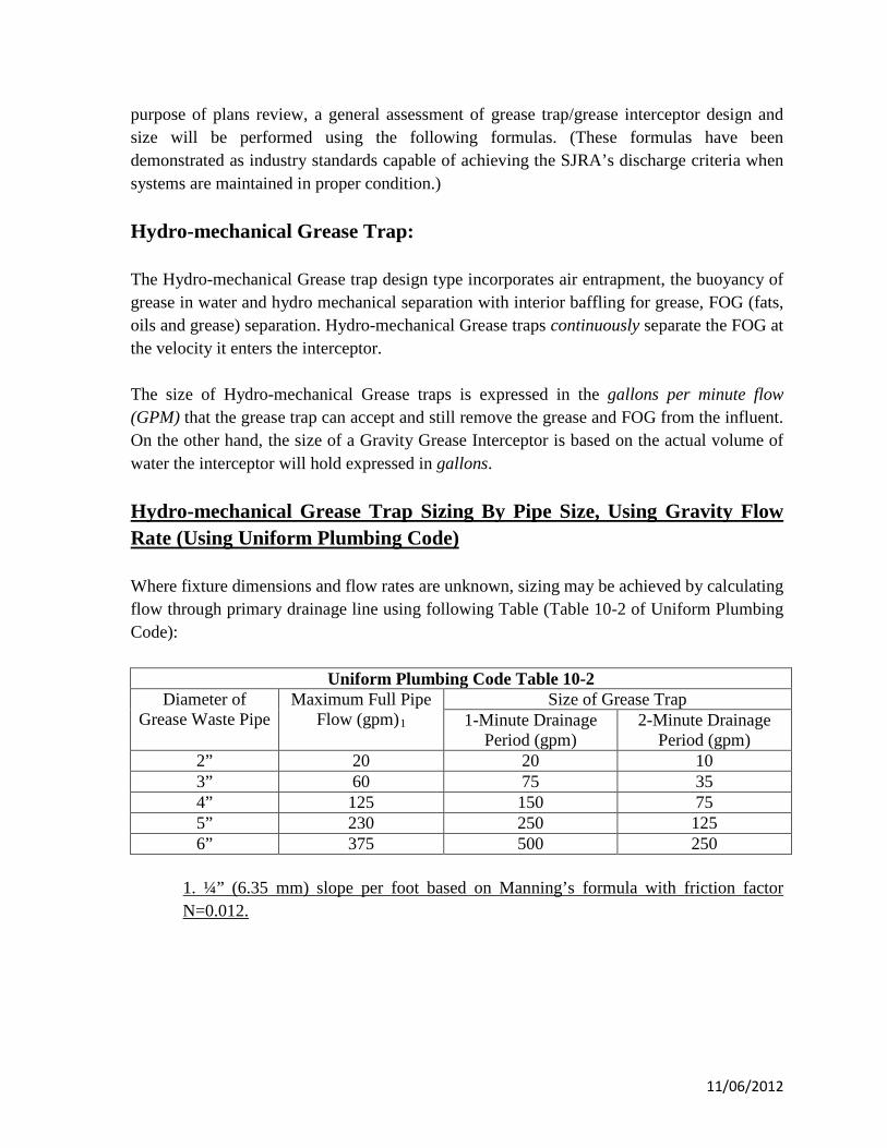
purpose of plans review, a general assessment of grease trap/grease interceptor design and size will be performed using the following formulas. (These formulas have been demonstrated as industry standards capable of achieving the SJRA’s discharge criteria when systems are maintained in proper condition.) Hydro-mechanical Grease Trap: The Hydro-mechanical Grease trap design type incorporates air entrapment, the buoyancy of grease in water and hydro mechanical separation with interior baffling for grease, FOG (fats, oils and grease) separation. Hydro-mechanical Grease traps continuously separate the FOG at the velocity it enters the interceptor. The size of Hydro-mechanical Grease traps is expressed in the gallons per minute flow (GPM) that the grease trap can accept and still remove the grease and FOG from the influent. On the other hand, the size of a Gravity Grease Interceptor is based on the actual volume of water the interceptor will hold expressed in gallons. Hydro-mechanical Grease Trap Sizing By Pipe Size, Using Gravity Flow Rate (Using Uniform Plumbing Code) Where fixture dimensions and flow rates are unknown, sizing may be achieved by calculating flow through primary drainage line using following Table (Table 10-2 of Uniform Plumbing Code):
Uniform Plumbing Code Table 10-2 Diameter of
Grease Waste Pipe Maximum Full Pipe
Flow (gpm)1
Size of Grease Trap 1-Minute Drainage
Period (gpm) 2-Minute Drainage
Period (gpm) 2” 20 20 10 3” 60 75 35 4” 125 150 75 5” 230 250 125 6” 375 500 250
1. ¼” (6.35 mm) slope per foot based on Manning’s formula with friction factor N=0.012.
11/06/2012
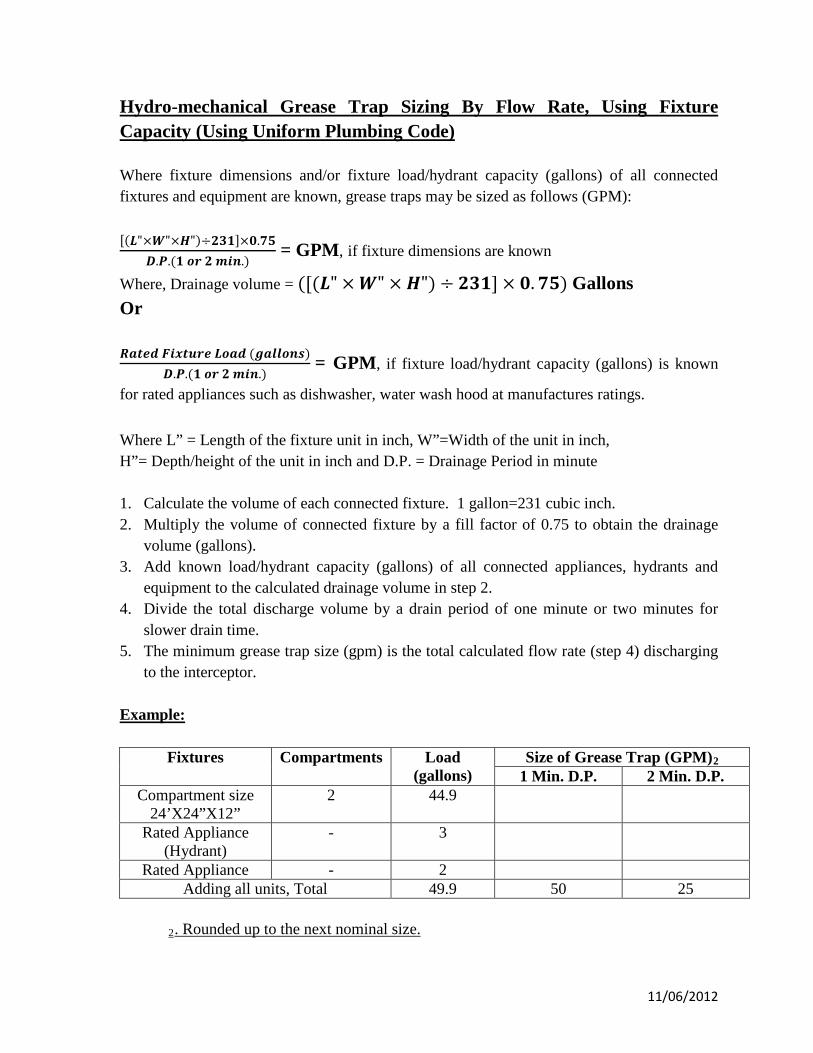
Hydro-mechanical Grease Trap Sizing By Flow Rate, Using Fixture Capacity (Using Uniform Plumbing Code) Where fixture dimensions and/or fixture load/hydrant capacity (gallons) of all connected fixtures and equipment are known, grease traps may be sized as follows (GPM): [(𝑳"×𝑾"×𝑯")÷𝟐𝟑𝟏]×𝟎.𝟕𝟓
𝑫.𝑷.(𝟏 𝒐𝒓 𝟐 𝒎𝒊𝒏.) = GPM, if fixture dimensions are known
Where, Drainage volume = ([(𝑳" × 𝑾" × 𝑯") ÷ 𝟐𝟑𝟏] × 𝟎.𝟕𝟓) Gallons Or 𝑹𝒂𝒕𝒆𝒅 𝑭𝒊𝒙𝒕𝒖𝒓𝒆 𝑳𝒐𝒂𝒅 (𝒈𝒂𝒍𝒍𝒐𝒏𝒔)
𝑫.𝑷.(𝟏 𝒐𝒓 𝟐 𝒎𝒊𝒏.) = GPM, if fixture load/hydrant capacity (gallons) is known
for rated appliances such as dishwasher, water wash hood at manufactures ratings. Where L” = Length of the fixture unit in inch, W”=Width of the unit in inch, H”= Depth/height of the unit in inch and D.P. = Drainage Period in minute 1. Calculate the volume of each connected fixture. 1 gallon=231 cubic inch. 2. Multiply the volume of connected fixture by a fill factor of 0.75 to obtain the drainage
volume (gallons). 3. Add known load/hydrant capacity (gallons) of all connected appliances, hydrants and
equipment to the calculated drainage volume in step 2. 4. Divide the total discharge volume by a drain period of one minute or two minutes for
slower drain time. 5. The minimum grease trap size (gpm) is the total calculated flow rate (step 4) discharging
to the interceptor. Example:
Fixtures Compartments Load (gallons)
Size of Grease Trap (GPM)2 1 Min. D.P. 2 Min. D.P.
Compartment size 24’X24”X12”
2 44.9
Rated Appliance (Hydrant)
- 3
Rated Appliance - 2 Adding all units, Total 49.9 50 25
2. Rounded up to the next nominal size.
11/06/2012
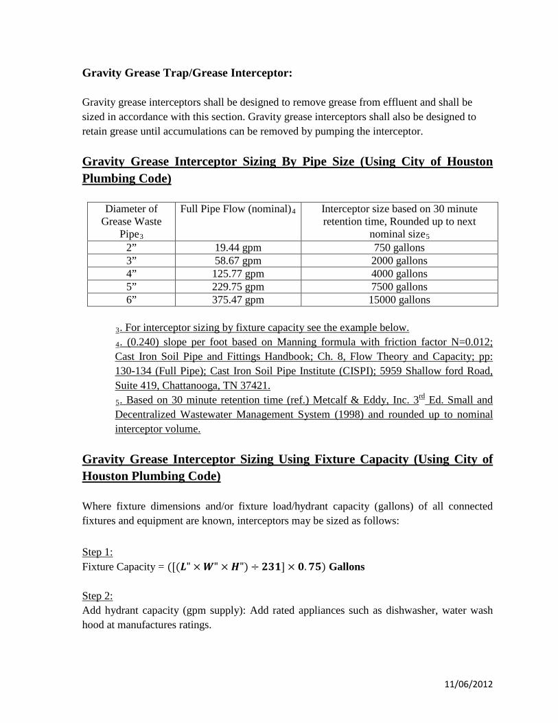
Gravity Grease Trap/Grease Interceptor: Gravity grease interceptors shall be designed to remove grease from effluent and shall be sized in accordance with this section. Gravity grease interceptors shall also be designed to retain grease until accumulations can be removed by pumping the interceptor. Gravity Grease Interceptor Sizing By Pipe Size (Using City of Houston Plumbing Code)
Diameter of Grease Waste
Pipe3
Full Pipe Flow (nominal)4 Interceptor size based on 30 minute retention time, Rounded up to next
nominal size5
2” 19.44 gpm 750 gallons 3” 58.67 gpm 2000 gallons 4” 125.77 gpm 4000 gallons 5” 229.75 gpm 7500 gallons 6” 375.47 gpm 15000 gallons
3. For interceptor sizing by fixture capacity see the example below. 4. (0.240) slope per foot based on Manning formula with friction factor N=0.012; Cast Iron Soil Pipe and Fittings Handbook; Ch. 8, Flow Theory and Capacity; pp: 130-134 (Full Pipe); Cast Iron Soil Pipe Institute (CISPI); 5959 Shallow ford Road, Suite 419, Chattanooga, TN 37421. 5. Based on 30 minute retention time (ref.) Metcalf & Eddy, Inc. 3rd Ed. Small and Decentralized Wastewater Management System (1998) and rounded up to nominal interceptor volume.
Gravity Grease Interceptor Sizing Using Fixture Capacity (Using City of Houston Plumbing Code) Where fixture dimensions and/or fixture load/hydrant capacity (gallons) of all connected fixtures and equipment are known, interceptors may be sized as follows: Step 1: Fixture Capacity = ([(𝑳" × 𝑾" × 𝑯") ÷ 𝟐𝟑𝟏] × 𝟎.𝟕𝟓) Gallons Step 2: Add hydrant capacity (gpm supply): Add rated appliances such as dishwasher, water wash hood at manufactures ratings.
11/06/2012
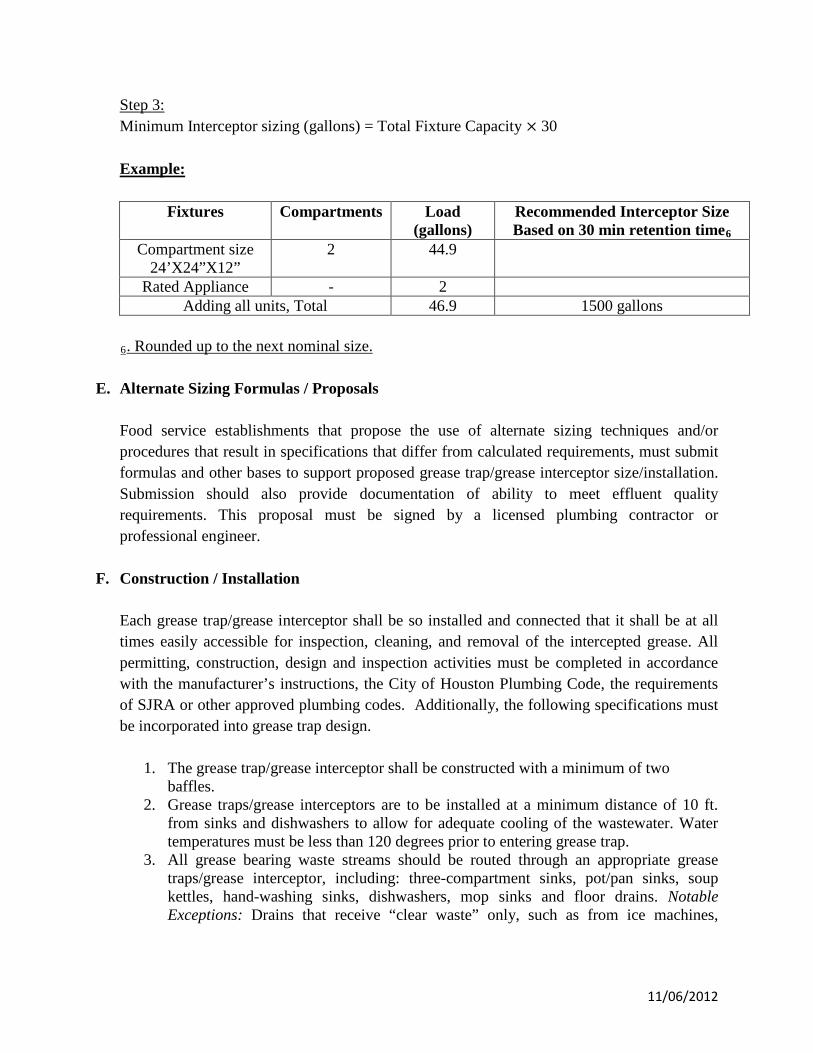
Step 3: Minimum Interceptor sizing (gallons) = Total Fixture Capacity × 30 Example:
Fixtures Compartments Load (gallons)
Recommended Interceptor Size Based on 30 min retention time6
Compartment size 24’X24”X12”
2 44.9
Rated Appliance - 2 Adding all units, Total 46.9 1500 gallons
6. Rounded up to the next nominal size.
E. Alternate Sizing Formulas / Proposals Food service establishments that propose the use of alternate sizing techniques and/or procedures that result in specifications that differ from calculated requirements, must submit formulas and other bases to support proposed grease trap/grease interceptor size/installation. Submission should also provide documentation of ability to meet effluent quality requirements. This proposal must be signed by a licensed plumbing contractor or professional engineer.
F. Construction / Installation
Each grease trap/grease interceptor shall be so installed and connected that it shall be at all times easily accessible for inspection, cleaning, and removal of the intercepted grease. All permitting, construction, design and inspection activities must be completed in accordance with the manufacturer’s instructions, the City of Houston Plumbing Code, the requirements of SJRA or other approved plumbing codes. Additionally, the following specifications must be incorporated into grease trap design.
1. The grease trap/grease interceptor shall be constructed with a minimum of two baffles.
2. Grease traps/grease interceptors are to be installed at a minimum distance of 10 ft. from sinks and dishwashers to allow for adequate cooling of the wastewater. Water temperatures must be less than 120 degrees prior to entering grease trap.
3. All grease bearing waste streams should be routed through an appropriate grease traps/grease interceptor, including: three-compartment sinks, pot/pan sinks, soup kettles, hand-washing sinks, dishwashers, mop sinks and floor drains. Notable Exceptions: Drains that receive “clear waste” only, such as from ice machines,
11/06/2012
condensate from coils and drink stations, may be plumbed to the sanitary system without passing through the grease trap.
4. All exterior or recessed grease traps/grease interceptors are to be installed with an Effluent Sampling Well.
G. Customer (Generator) Responsibilities It is the responsibility of the customer (waste generator) to ensure compliance with the SJRA discharge limitations specified in SJRA Grease Order. Hazardous wastes, such as acids, strong cleaners, pesticides, herbicides, paint, solvents, or gasoline should not be disposed of where they would go through grease traps, interceptors or separators. If commercial dishwashers are discharged through a grease trap, care must be taken in system design. Dishwashers use detergents and elevated water temperatures that will melt grease. If the grease trap is either too small or too close to the commercial dishwasher, grease may pass through the grease trap and into the collection system. Generators are responsible for maintaining grease traps, interceptors and separators in continuous proper working condition. Further, generators are responsible for inspecting, repairing, replacing, or installing apparatus and equipment as necessary to ensure proper operation and function of grease traps, interceptors and separators, and compliance with discharge limitations at all times. The generator must have grease traps, interceptors and separators serviced (pumped, cleaned, and inspected) by a TCEQ licensed and SJRA registered waste hauler, at a minimum frequency of every 90 days or more often as necessary, to ensure proper function. Records of servicing (waste manifest) are required to be maintained on site for five (5) years. The 90 day servicing frequency assumes proper sizing and installation consistent with this guidance. Any person who owns or operates a grease trap, interceptor or separator may submit to SJRA a request in writing for an extension to the ninety (90) day pumping frequency. SJRA may grant an extension for required cleaning frequency on a case-by-case basis. In any event, a grease trap, interceptor or separator shall be fully evacuated, cleaned, and inspected at least once every 180 days. Enzymes, solvents, and emulsifiers are not permitted as they will only change the form of grease, allowing it to be carried out of the grease trap with the wastewater and deposited in the collection system.
11/06/2012
H. Food Waste Disposal Units Unless specifically required or permitted by the Authority, no food waste disposal unit shall be connected to or discharge into any grease interceptor. Commercial food waste disposers shall be permitted to discharge directly into the building’s drainage system.
11/06/2012
Part II: Guidance for Interceptor and Separator Sizing and Design Criteria
Interceptors and separators are required for oil, grease, sand and other substances harmful or hazardous to the building drainage system, the public sewer or sewage treatment plant. Design, size, and location of pretreatment devices must be submitted by a licensed plumbing contractor or professional engineer for review and approval. A. Laundries
Commercial Laundries, Laundromats, and dry-cleaners shall be equipped with a lint interceptor in order to reduce the quantity of lint and silt that enter the collection system. The system must be of adequate size and design to allow for cool-down of wastewater so that separation can be more readily achieved. Laundry equipment in commercial and industrial buildings that does not have integral strainers shall discharge into an interceptor having a wire basket or similar device that is removable for cleaning and that will prevent passage into the drainage system of solids ½ inch (12.7 mm) or larger in maximum dimension, such as string, rags, buttons or other solid materials detrimental to the public sewerage system. An approved lint interceptor shall be installed for all commercial laundries. Exceptions:
1. A laundry containing no more than 4 automatic clothes washers 2. A laundry in an R-2 Occupancy containing no more than 10 automatic clothes
washers
For other than a mechanical lint interceptor properly sized to manufacturer’s instruction, see the Appendix: Drawings LT-1, LT-2 and LT-3 for minimum size and construction criteria.
The lint interceptor should be cleaned (or pumped out) routinely to prevent the escape of appreciable quantities of grease. Cleaning should be performed when the interceptor is at 75% of lint/silt retention. The frequency of cleaning at any given installation will vary depending on use. Pumping frequencies for Laundromats usually range from once a month to every six months.
B. Minimum Requirements for Auto Wash Racks Every private of public wash rack and/or floor or slab used for cleaning machinery or machine parts shall be adequately protected against storm or surface water and shall drain or discharge into an interceptor (clarifier) of an approved design for this use. See Appendix: Drawing MT-1 for minimum size and construction criteria.
11/06/2012
C. Hair Trap Hair discharged in amounts which will cause interference, pass through, or obstruction to the flow in the POTW is prohibited. Hair traps are required whenever SJRA deems it necessary. SJRA may require hair traps for beauty salons, barber shops, pet grooming facilities, hospitals or wherever hair clogging is a problem. At a minimum, the hair trap unit shall be designed with 1-1/2” inlet and outlet and is capable of handling the drainage volume for 1-1/2” pipe size. Trap sizes shall not be increased to the point where the fixture discharge may be inadequate to maintain their self-scouring properties. City of Houston Plumbing Code shall be applicable. Cleaning should be conducted in accordance with manufacturer's instructions and before the unit becomes clogged.
D. Sand/Grit Interceptors (Using Uniform Plumbing Code) Whenever the discharge of a fixture or drain contains solids or semi-solids heavier than water that would be harmful to a drainage system or cause a stoppage within the system, the discharge shall be through a sand/grit interceptor. Multiple floor drains shall be permitted to discharge into one sand interceptor. Sand interceptors are required whenever POTW deems it advisable to have a sand interceptor to protect the drainage system. Sand interceptors shall be built of brick or concrete, prefabricated coated steel, or other watertight material. The interceptor shall have an interior baffle for full separation of the interceptor into two (2) sections. The outlet pipe shall be the same size as the inlet pipe of the sand interceptor, the minimum being three (3) inches (80 mm), and the baffle shall have two (2) openings of the same diameter as the outlet pipe and at the same invert as the outlet pipe. These openings shall be staggered so that there cannot be a straight line flow between any inlet pipe and the outlet pipe. The invert of the inlet pipe shall be no lower than the invert of the outlet pipe. The sand interceptor shall have a minimum dimension of two (2) feet square (0.19 m2) for the net free opening of the inlet section and a minimum depth under the invert of the outlet pipe of two (2) feet (610 mm). For each five (5) gallons (18.9 L) per minute flow or fraction thereof over twenty (20) gallons (75.7 L) per minute, the area of the sand interceptor inlet section is to be increased by one (1) square foot (0.09-square meter). The outlet section shall at all times have a minimum area of fifty (50) percent of the inlet section. The outlet section shall be covered by a solid removable cover, set flush with the finished floor, and the inlet section shall have an open grating, set flush with the finished floor and suitable for the traffic in the area in which it is located.
11/06/2012
Sand and similar interceptors for every solid shall be so designed and located as to be readily accessible for cleaning, shall have a water seal of not less than six (6) inches (152 mm), and shall be vented.
E. Oil and Flammable Liquid Separator (Using Uniform Plumbing Code)
All repair garages and gasoline stations with grease racks or grease pits, and all factories that have oily, flammable, or both types of wastes as a result of manufacturing, storage, maintenance, repair, or testing processes, shall be provided with an oil or flammable liquid separator that shall be connected to all necessary floor drains. The separation or vapor compartment shall be independently vented to the outer air. If two (2) or more separation or vapor compartments are used, each shall be vented to the outer air or shall be permitted to connect to a header that is installed at a minimum of six (6) inches (152 mm) above the spill line of the lowest floor drain and vented independently to the outer air. The minimum size of a flammable vapor vent shall be not less than two (2) inches (50 mm), and, when vented through a side-wall, the vent shall be not less than ten (10) feet (3,048 mm) above the adjacent level at an approved location. The separator shall be vented on the sewer side and shall not connect to a flammable vapor vent. All oil and flammable separator shall be provided with gastight cleanout covers that shall be readily accessible. The waste line shall be not less than three (3) inches (80 mm) in diameter with a full size cleanout to grade. When a separator is provided with an overflow, it shall be provided with an overflow line (not less than two (2) inches (50 mm) in diameter) to an approved waste oil tank having a minimum capacity of five-hundred fifty (550) gallons (2,082 L) and meeting the requirements of POTW. The waste oil from the separator shall flow by gravity or shall be pumped to a higher elevation by an automatic pump. Pumps shall be adequately sized and accessible. Waste oil tanks shall have a two (2) inch (50 mm) minimum pump-out connection at grade and a one and one-half (1-1/2) inch (40 mm) minimum vent to atmosphere at an approved location not less than ten (10) feet (3,048 mm) above grade. Each manufactured separator that is rated shall be stamped or labeled by the manufacturer with an indication of its full discharge rate in gpm (L/m). The full discharge rate to such a separator shall be determined at full flow. Each separator shall be rated equal to or greater than the incoming flow and shall be provided with an overflow line to an underground tank. Separators not rated by the manufacturer shall have a depth of not less than two (2) feet (610 mm) below the invert of the discharge drain. The outlet opening shall have not less than an eighteen (18) inch (457 mm) water seal and shall have a minimum capacity as follows: Where not more than three (3) motor vehicles are serviced and/or stored, interceptors shall have a minimum capacity of six (6) cubic feet (0.17 m3), and one (1) cubic foot (0.03 m3) of capacity shall be added for each vehicle up to ten (10) vehicles. Above ten (10) vehicles, the Authority shall determine the size of the separator required. Where vehicles are serviced only and not stored, separator capacity shall be based on a net capacity of one (1) cubic foot (0.03 m3) for each one-hundred (100) square feet (9.29 m2) of surface to be drained into the interceptor, with a minimum of six (6) cubic feet (0.17 m3).
11/06/2012
Note: Parking garages in which servicing, repairing, or washing is not conducted, and in which gasoline is not dispensed, shall not require a separator. Areas of commercial garages utilized only for storage of automobiles are not required to be drained through a separator.
F. Slaughterhouses, Packing Establishments, etc. Every fish, fowl, and animal slaughterhouse or establishment; every fish, fowl, and meat packing or curing establishment; every soap factory, tallow-rendering, fat-rendering, and hide-curing establishment shall be connected to and shall drain or discharge into an approved grease interceptor (clarifier).
G. Bottling Establishments
Bottling plants shall discharge their process wastes into an interceptor that will provide for the separation of broken glass or other solids, before discharging liquid wastes into the drainage system.
11/06/2012

APPENDIX
DRAWINGS FOR INTERCEPTORS
11/06/2012
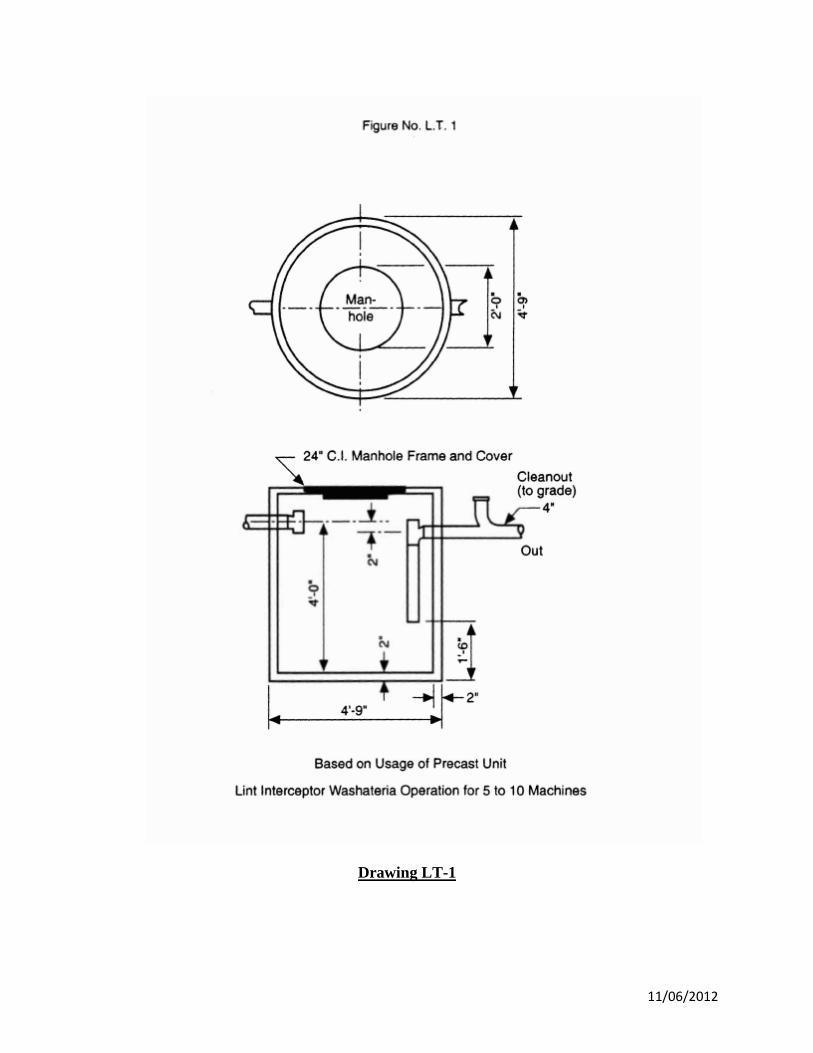
Drawing LT-1
11/06/2012
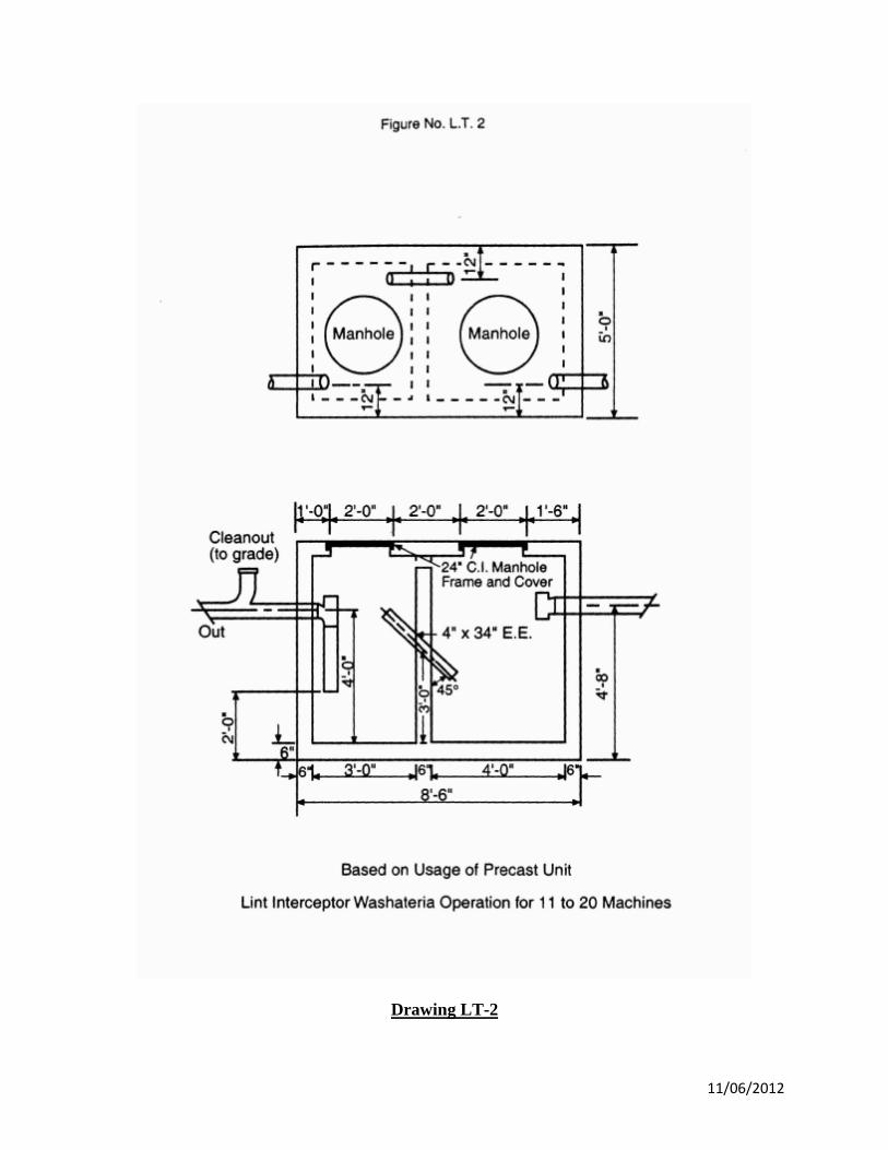
Drawing LT-2
11/06/2012

Drawing LT-3
11/06/2012
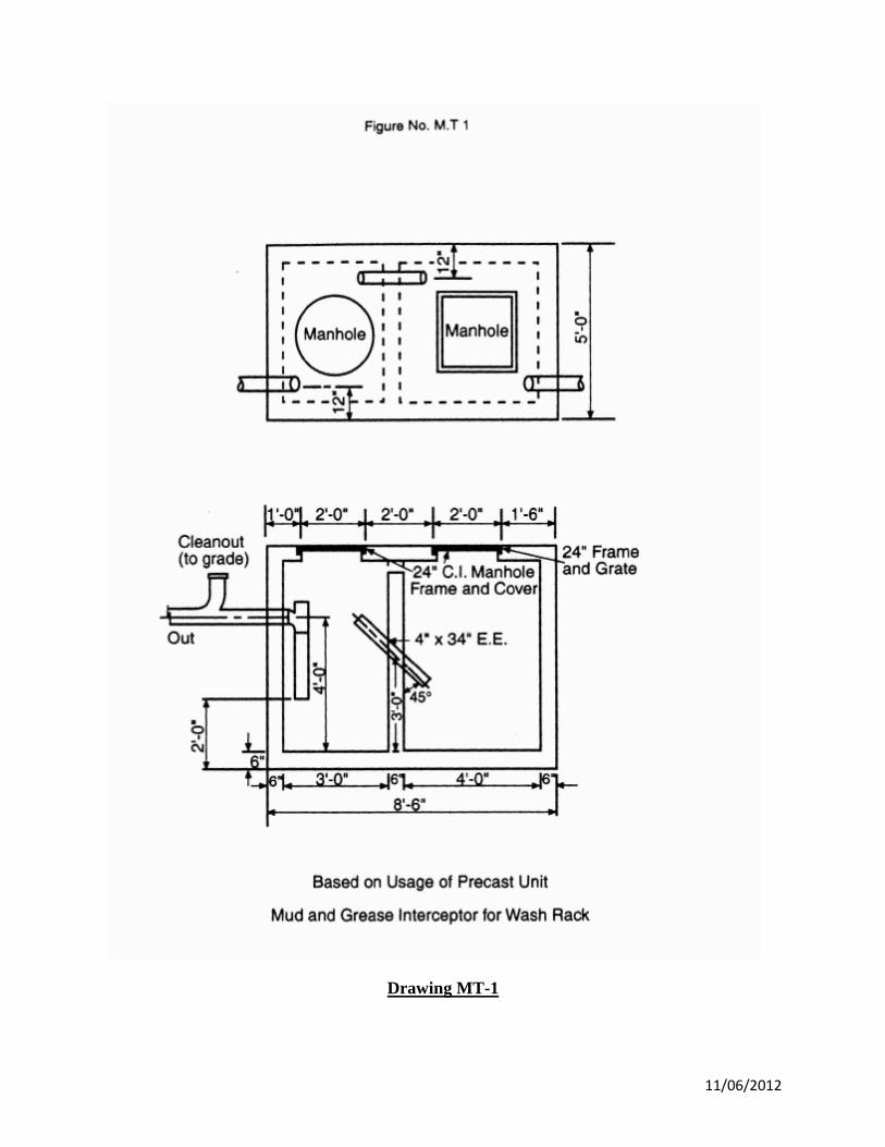
Drawing MT-1
11/06/2012