gretton 99
DESCRIPTION
Gretton 99TRANSCRIPT
DESIGN OF CHIMES TO PRODUCE CONSONANT, NON-HARMONIC SCALES Arthur Gretton Department of Engineering, AustraJian National University, Canberra 0200
ABSTRACT: Thin, cylindrical metal chimes can be used to play in a variety of scales requiring non-harmonic spectra The speclrum Il'quired for the chimes to have collSOIllllltintervals in a given non-harmonic ocale can be detertnined acoord ingtoamethoddevelopedby Sethares,based on the theory of dissonance proposed by Plomp andLevelt First order perturbation theory was appHedto eontrol the frequencies of the first six modes ofa thin, cylindrical metal chime by perturbations to the chime radius. The resultant chime profile was then refined using finite eiemellt methods. Twa alwninium chimes manufactured with this optimised profile demonstrated superior musical peIformance compared with unperturbed thin cylinders.
1. INTRODUCTION Thc majority of non-percussive musical instruments eurrently used in the West produce spectra consisting of hannonically related frequencies. That is to say, notes played using these instruments have partials that are nearly integer multiples of some fundamental frequency to. Such harmonic spectra are caused by a control oscillator (such as a reed, lip reed or air jet in wind instruments, or a bow in string instruments), or by the intrinsic properties of the vibrating elements used in these musical instruments, wholiC natural frequencics arc almost exactly harmonic. Examples of the latter are long, thin, unifonn, flexible strings.
When two produced by a harmonic musical .instrument are played together, the sound produced can be eithcr consonant, meaning pleasant and T<llaxed, or dissonant, meaning discordant and tensc. Although there is ;1ill speculation regarding the quantitative measurement of dissonance., Plomp and Levelt [1] have proposed that the perceived dissonance between twu notes is exclusively a function of the location and amplitude of the partials making up these notes. This lheory of dissonance is widely accepted
Various scales have been developed that make use of the dissonance properties of the hannonic speetrum to ensure that a fairly large range of intervals sound reasonably consonant. The 12 tone equal temperament (12-tet) scale has been widely adopted so that free modulation from one key to another is possible.
Many objects that are used, or could potentially be used to produce music, bowever, do not have harmonic spectra. Thus they sound discordant when played in chords using notes in a scale designed for harmonic i1llltruments, such as the 12-let scale. In addition, many modem composers are interested in writing music for scales other than 12-tct, which reqnire spectra that no readily available, non-electronic llIUSical instrument is able to produce. An approach to designing spectra for non-harmonic scales was fonnulated by Sethares in [2,3].
One class of non-harmonic objects with potential for wider musical applicatioos are thin cylindrical metal chimes. In this project, a design process was developed that can be used to create a set of such chimes that have a range of coosonant
intervals fur a given oon-harmonic scale. Sctharcs' approach was used to determine the chime speCInnn for the non-harmonic scale under consideration.
Previous work in the design of musical instnunents with non-harmonic spectra includes the Pentangle by Fletcher [4]. The Pentangle consists uf a pentagonal gong tuned to produce a bell-li1re spectrum, using a combination of analytic and finite element methods. A similar approach was followed in this study, in that analytic methods were used fur basic chime dcsign, and the chimc profile was then rcrmed using the finite element llillIlysis package STRAND 6. Such an approach dttfers from the method used by Petrolito and Legge [5], who applied finite element methods alone to tune the first three modes of xylophone bars with rectangular cross sections . Thus while the approach adopted by Petrolito and Legge was to constrain thc finite element optimisation process using criteria such as the minimisation of material to be removed, the approach of this work and of Fletcher WllS to limit the finite element based optimisation to solutions close to results
using simplified theoretical models of thc system. As far as we are aware, however, this study is the first attempt to produce a· non-electronic musical instrument that implements Sethares' method of selecting a spectrum for a =10 2_ CHIME FREQUENCY SIllFT CALCULATION USING PERTURBATION THEORY The theoretical model that was used to obtain a chime profile that produces a close approximation to the desircd spectrum is described. Equations are given for the bending modes of a thin, cylindrical rod, and then a general is introduced to describe the frequency sbifts callSed by perturbations to a vibrating abject. Next, this theory is used to predict the shifu; to rod frequencies when small changes are made to the radillS ofarod
Finally, this theory is applied to the specific problem of controlling the frequencies of a cylindrical metal chime. The problem of achieving the chime goal frequencies while minimising thc changes to chimc radius is also addressed, since the perturbation theory predictions will only be accurate for small changes to the rod profile.
Vol. 27 (1999) No.1 -11
2,1 Bending wave equation for a rod The general ", .. :w e equation for bending waves in a uni form
rod is [6]
(I)
where E is the YilUng's modulw;, S i, [he eros, sectional area (S=rrr' for a cylindrical rod), K is the radius of gyration about the neotral axis (K= rf2 fora cylindricai rod),p is thedensity, x is the position along t he rod as measured rrom the middle, r is time, and W(.u) is the of the rod fTOm equilibrium,
Eqoation (I) is a "thin beam" approximation that neglects such effect, as shear and rotary inertia, and on ly models bending modes. For this appHlximation to be tr ue, the wavelength of the modes mu,t be large compared "ith the rod diameter, since otherwise shear distortioo is non-negligible in comparison with bending, Since we on ly considcrthe first six m(K\es of the rod (the most audible modes), this tnmslate> as a requirement that the length 10 dimeter ratio for the roo should be around 60:1 or greater. In practice, this requirement may be relal<ed a little.
The solutions to (I) take the form of sums of members of theserie.
'1'. - l/I.(x)cos(m.t). (2)
(3)
Here v. - (wl- ;dpj" is the wave velocity of mode n with angular freqllency W., alldA" B .. C. and D, are COnstallts.
For a rod wi th both ends free, the solutions to equation (I) have A,- C.-o lor even 1/ and B,=D.«fJ for odd n, 1\', is C\'CIl for odd n and odd for even n. Bendingosc illationsina rod of COil stant radius with both ends frce occur at frequcllcies f .. given by
2,2 Frequenq shifts to a cylindrical rod due tn in rod radius A general perturbation theory that can be used to determine the en"ect on rod frequencies of perturbations to the rod radius is now deseribed_ This theory takes a form similar 10 that proposed by Tsc, Morse and Hinkle [7]. Only first order pcnurbations will be taken into account. which means that the frequell CY >hifts predicted are appro,;imatc As a starting point, il is to .....nle (1) in the form
(5)
whe,.,., S is a !inear dilferential operator, given by
(6)
12 - Vol. 27 (1999) No. '
perturbations
in (5). Expanding (5), and retaining only first order or lower terms, g1V(:S
where we have written C • • for ease ofreference. We now derive a formula for the 1;,. due to perturbations ill
the rod radius . The expression for ill thc case ofthc rod is givcnby (6). l\.l aking the ehanges ,....rt-br(x) and in (6), retaining only fin;t order and lower tenns in the resulting expansion, and then substituting thi s expression for b:J into (R) , gives
C. ' ( J"«),:)" ,'*'J] f.("';'l';;,.ll],'" (9)
( to)
2.3 Design of a chime a spet:ified set of frequencies Equat ions (9) and (8) may now be nsed to obtain a cylindrical metal chime whose rrequencies of bending oscillation can be assigned spccified values, Given that N mode frequencies are to be eontroUed, the perturbation to the chime radius will take the form of a srun of N terms,
(II)
wher-c thellr.(x) repre>enl perturbation> to the chime radillSas fun d ions of longi tudinal coordioate x, and each constant b. scales the perturbation m. A set of functions for thc is flow choscn, with the iotention thateach perturbing function should have as large an effect as possible on only one modal freqncncy, and a minimum effect on all other frequencies
For a given increase in chime radins 6r, the sti ffnoss will increase by a factor l+4br whi le the mass will increase by 1+2br. In addition, for all modes, regions of high latend
from equilibrium correspond 10 regions of large curvature over most of the chime (the e,; ception being near the ends, where thc ditoplacement is significant but the CUJVature approaches zero). Therefore if the chime radius is ine,.,.,ased in regions where a given mode has a large curvature, then thc freqncney increase for this mode due to the higher stiffness will be greater than the drop in frequency due to the increased ma:;s, ami thc net effect will hcan incrca,e in lll()de frequency.
From Ihis property, il seems likely that the perturbing functions will have larger effecls on unique mode frequcncies if each perturbing function only has a large arnpJirude \\1Jere the mode that it targets has large enrvature. Thus the set ofpcrturbing functions adopted is
AeOUSlicsAustrali a
The purpose of the integral is to avoid applying an upwards shift on all modes when the radius is penurbed. Substituting(Jl) into (9) aUows (9) to bc rewritten as
(13)
where
Uo .. -f:,( -To: Cn[f,( (14)
Once the N desired frequency shifts 0010 have been speeificd, (8) maybc solved 10 obtaintheNquantitiesl;... The SCI oflinearcqualions (J3) can then be soJvedto givc the amplitudcs of the perturbing functions in (11).
3. CHOOSI NG A TARG ET SPECT RUM Now that an approximate process for controlling thc frcqueneiesofacylindrical chime has been iHustrated,the chime goal spectrum that .... as used to test this proccdure is described. Given that the object of this project to find a design process that can be used to create chimcs for a givcn sca1c,wededded to tcst this process by sclccting a genuinely arbitrary scale and working towards a set of chimes with appropriate spectra
The scale that was chosen for the chimes is an unequally stretched Pythagorean major scale. The unstretchcd l>ythagorean major scale sounds quitc similar to the l2-tet major seale, but with slightly sharper major thirds and slightly ftallcrminor thirds (3]. The steps of the Pylhagoreanscale, whether stretched orunstretched, can be written
(1. a, a'. a'h, a't., a' h, a'b, a'b')"I. ' (15)
where/, rerrescnts the frequency of the first note in the scale and <I and b are tbe two basic frequency step ratios. The ROtation in (IS) means that the first ROte in the seale has frequency Ix/ .. the second note has frequency ax/ .. and so on. The unstretched Pythagorean scale has and b=2561243. Our stretched seale had a=6J5 and "," 16.115. This means that the"octave" (literally thc eighth note) occurs at 1.990.656 / 703,125 .. 2.83 times the frequencyofthc lowest TlOtcin this scalc, rathcrthan the usual faClOrof2 for unSlretehed scales. For this reason. the tenn p)·eudo--<>ela,"C will be uscd to dcsignate the stretcl!ed"oclavc" interval
One possible chimespeclTUm for the seale described in (15). as detennincd using the procedure outl ined by Sethares [2 .3], is
where the notalion of equation ( 15) has been used and the number of partials is N - 6. The required frequency shifts 10 the modes of the unperturbed chime. as fractions of the unperturbcdmodefrequencies.V3ryfrom -8% 109".4
ACOUSlicsAuslfal ia
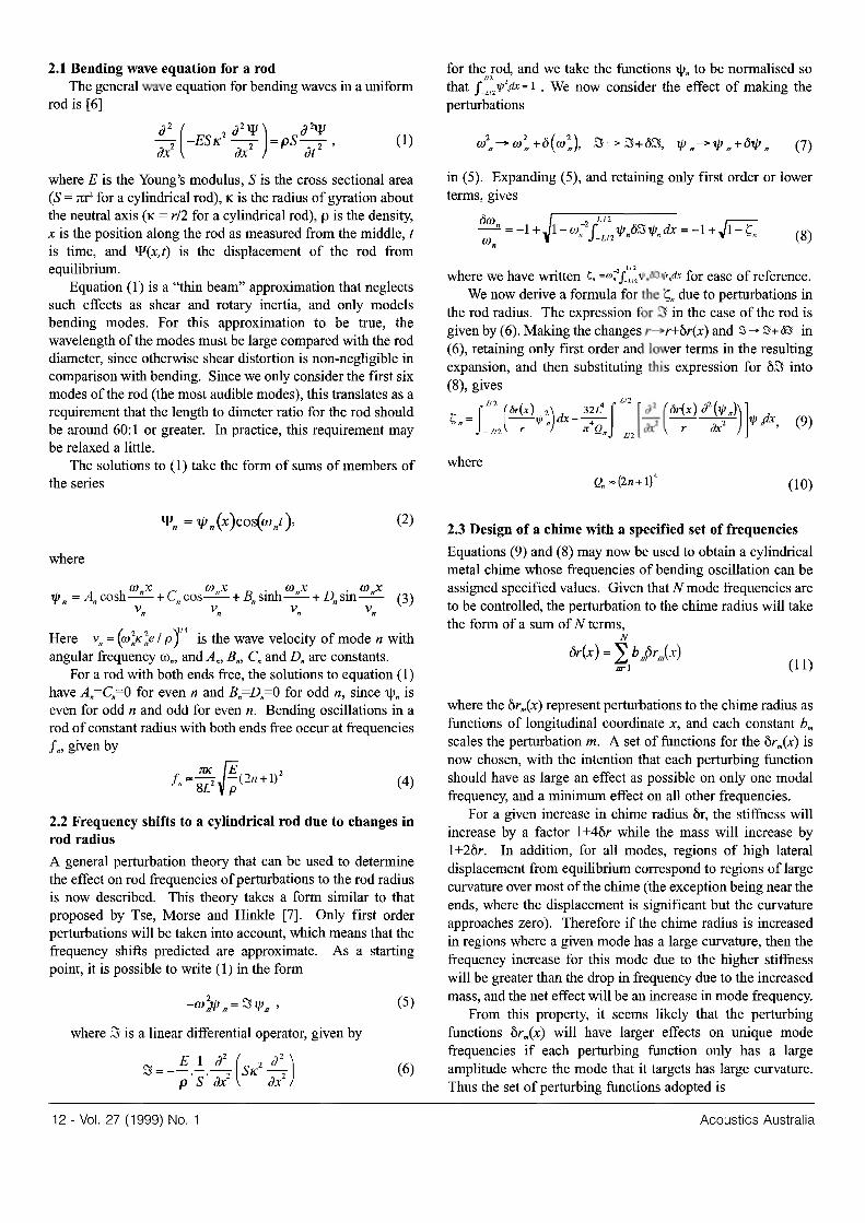
To see why thc target spe<:lTUm in equatiQn (16) rcpresenls a good spectrum for the scale in (15), it is necessary to introduce !he concept of the diSSQnarr.cecurve for a spectrum This is a plot of the dissonance (as dermed by Plomp and Levcl! [1]) perceived when two notes are played simultancously, wherethc frequencicsofthe panialsofthe higher nOle are increased by a factor R with respect to the partials of the 10weT note. Plomp and Levclt found that whcn Ihese two notes are pure sinusoids, the dissonance d(u J•
J,) between them isa funct ion of the amplitudesuJ and a, of thcsinusoids,andtheirfrcquencics/, and/," Thedissonance berween the sinusoids iSlcro when Iheir frequencics are equal, riscs rapidly liS the frcqucncy diffcrence increa.ses. and then drops slowly upon further incrcase in Ihe frequency difference. A plot orthe dissonance between two sin\l5Oids is given in Figure I, where a, - <I , - I andf, - R >< f,. Plomp alld Levcll found thai this function d(a" closely approximated Ihe average dis.o;onance measured ina series of tests involving 90 musically untraincd volunleers
The dissonance g(R) of a spe<:trum containing partials al scveralfrcqueneicsisobtainedbyaddingthedissonanceof cvcrypai r ofpanials,sothat
(\7)
wllere a; and aJ are the amplitudes of the partials with frequcncies J.and f, rcspectivcly. The dissonancccur ... e fora givcnspcctrum is a plot ofg(R) for that spectrum.
F'ilQuencv ratio R
figuret : dissonance between rnosinusoidswithf""'lucnciesf, and/" whcrof, oo R><f,. Thesinusoidshavccqualarnptitudc.
The dissonance curve for the spcctrum in (l6)is illustrated in Figure 2, whcre stems an: used to show the location of the slepsofthe seale described in (15). We see from Ihis plol that dissonance is low at mosl of the seale steps, indicating that chords played using thesc intervals will sound pleasant
Vol. 27(1999) No. 1 - 13

· , , ,
J 0
J I\; rv , FrequencyralioR
11\1\
Figure 2: Dissonanoe curve ofa the stretched Pythagorean ",,"Ie, for tile spe<:tnlm defined in (Ilil. !OIaw; representtiwinten'3.lsdefmedin(15). lunplitudcsofaU partial<areasswne<iequllltoone.
4. DESIGN OF THE CmME The approximate chime design procedure described in section 2 "''liS applied to design" chime to play in the goal spcctrwn. A finite clemenl mooel of was used a fast and inexpcTlSive means of testing and refining tbe results obtained using perturbation theory. The finite element model was fOrmulated using the STRAND 6 finite clemenl packuge. 4..1 Chime profile obtained pertnrbation theory The profile for a chime that produces the spectrum given by (J6) was generated in accordance with section 2.3. The unperhlTbedcyJimlt:ron which the chime was based has length L=O.5215m and diameter 6.02mm. These dimensioru; satisfY the thin rod approximation for the firs! six modes as described in 2.1. The sill perturbing functions for the chime, detennincd in accordance with equation (12) of section 2.3, are illustrated in Figure 3
I f 0 .:
_1 __
PertlJ"t>i"1l !u"l<;l'>nJ ..... ,,'>lngt,.-.cuoo.
! .fAWAj' Figure3:The .ixperturbingfunctioruforthechime
14 -Vol. 27(1999) NO.1
The solid profile in Figure 4 illustrates the chime obtained by summing the sca led perturbing functions and adding the result to the unperturbed cylindrical chime. it ",as 1I0t possible to manufacture the smooth profile illustrated in Figure 4, the chimes were too long and thin to 00 machinable wiing a computer controlled lathe, and the sinusoidal was too difficult to reproduce by band. For this reason, a step approximation to the prome, as illustrated by the dashed curve in Figure 4, was designed. Although this step approximation caused slight shifts to the goal frequencies, these remained .mall (0_7% oflhe original goal frequencies at most, when using perturbation thoory), and were in any case reduced by the refinement proce!i-' to be described in the following section.
o DlstallCltalong chjme
Figure 4: Profileootained usingfrrstordcr",,'Ilurbation\heory, and manufacturab le step to this profile -: idealprofile ...
4.2 Refinement of chime prome using finite dement metbods The finite element analysis package STRAND 6 wa< used to model the chime shown in the step approximation from Figure 4. The natural frequencies calculated by the finite element model for this chime profile differed from the goal frequencies by amounts ranging from 2.0"10 to -2.4%. of the goal frequencies An improvement in the musical performance ofthe chimes, howcver, is deemed to occur when the differences between the goal frcquencie> and the STRAND 6 simulation frcqllencies drop below 1%, since our experience (based on a computer simulation or "chime-like" chords) 1-'.'35 that perceptible improvements in consonance occur once the error in the panial frequencies falls below 1%.
For this reason, an optimisation process was undenaken using STRAND 6. Small changes to the profile of the finite element model were made, and the changes to the natural frequencies calculated by the model were observed. This data was used to make small changes to the chime profile that improved the agreement of the calculated chimc frequencies with the goal frequencies. Simulation of the optimiscd profile in STRAND 6 resulted in frequency differences hetween the simulation and goal frequencies of 0.89% of the goal
Acoustics Australia
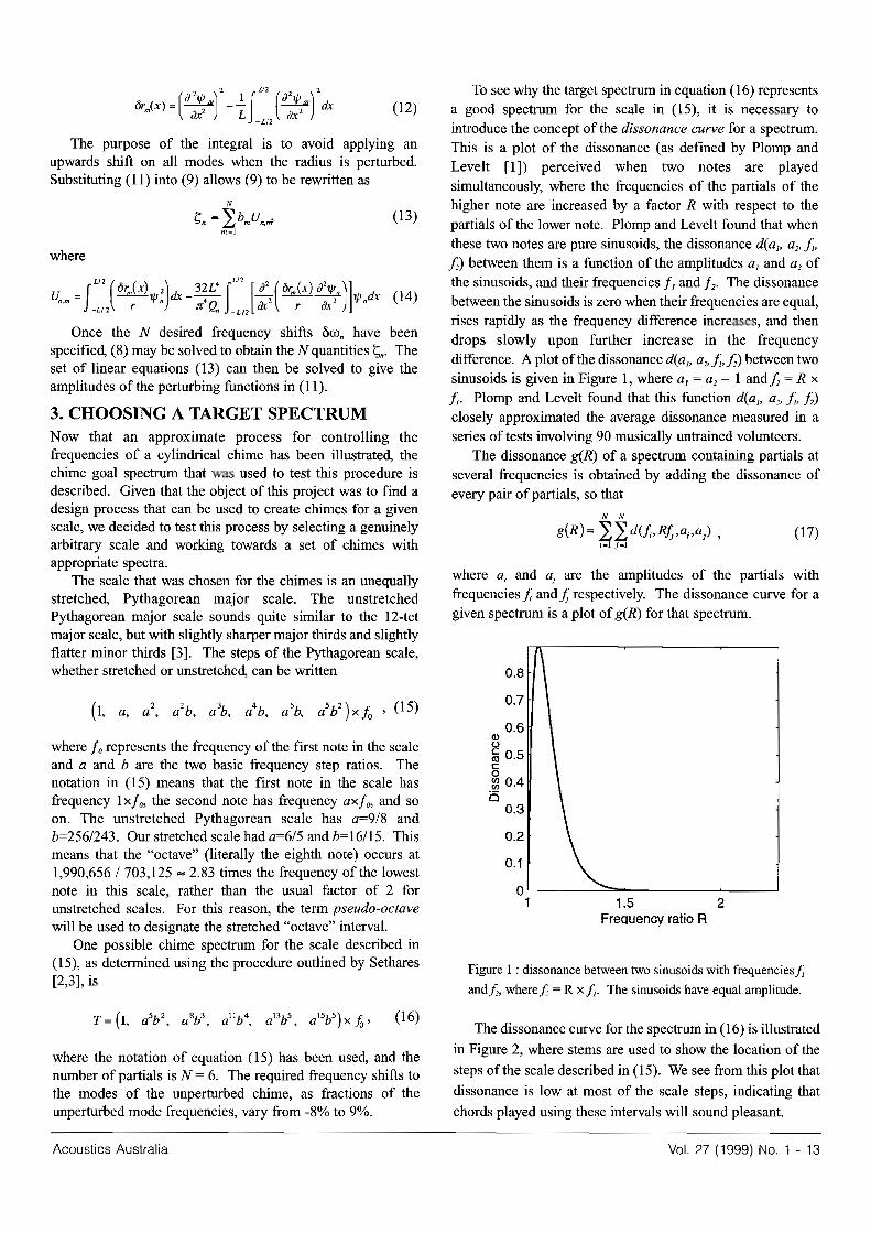
frequencies or less, which is below the le,·e1 "I' 1% mentioned become too difficult to The dimensions of the two above. The optimiscd profile is illustrated in Figure 5. chimes manufactured are given in Table I . Both chimes w"","
, Distance along chime
Figure 5 : Chinle prolilc obtained using STRAND 6
-:STR.'l.ND6optimised .... ·perturootiootheoryonly.
5. l\lANUFACWRlNG AND TESTING THE CHIMES The chime design arrived at using STRAND 6 optimisation was tested experimentally by manufacturiDg two chimes, and measuring their frequencies of oscillation. nil results of these mca>urcments arc sll11lll1llrised, and explanations are proposed for the differences the measured results and the STRAND 6 frllquencies 5.1 C himc dimension selection Since funds were only available to make two chimes, these chimes were designed so that one plays a "pseudo·octave" above the other. reason for thi> is that this interval represents the limits ofthc seale in which the chimes are to be played. Thus the interval gives a good indication of whether the:;e limits are attainable using the cbimes. Another advantage of using this interval is that unperturbed chimes sound dissonant when played in the same interval. Enaliy, the octave is usually tbe mnst cnnsonant inter;al in the commonly used temperaments, and so it is especially interesting to improve its consonance in new t imbreltuning combinations.
A fundamental of around 170Hz was chosen for the chime that plays the tonic in the intcrval. This ensures that tbe fi rst six panials of both chimes are audible, When scaling the chimes to produce these two notes, a constant average radillS was maintain.,.] and only the chime lengths were varied. This causes tho radiated sound volumc from botb chimes to be fairly similar.
A disadvantage of this scaling method is Ihallhe length to diameter ndio for IlK: chime is at most 35: 1, which is bolow the ratio required fnr tbe Ihin rod approximati<JTl to hold for the fOllrth to sixth modes. The predi<.;ted by STRAND 6 for these modcs, especially for the fitlh and sixth modes, may therefore be inaccurate. This elIccl could be countered using thinner chimes, however such chimes would
Acoustics Australia
turned from an alwniniwn rod using a manually controlled
""" Table I : tonic chime.
Dimension Tonic chime Octave chime LengthL(nun) 372.8 221.7 Mean diameter (mm) 5.83 5.83
5.2 Measurement of manufactured chime frequencies, comparison with STRAND 6 model, The cbime frequencies were measured lL'ing a microphone
to a computcr. Sound from the microphone OUlpllt was sampled for 2 seconds at 44. lkHz, and the frequency spectrum was obtained by taking the FFT of this signal Chimes were suspended using conon to simulate the boundary conditions (the chime must be free at both ends).
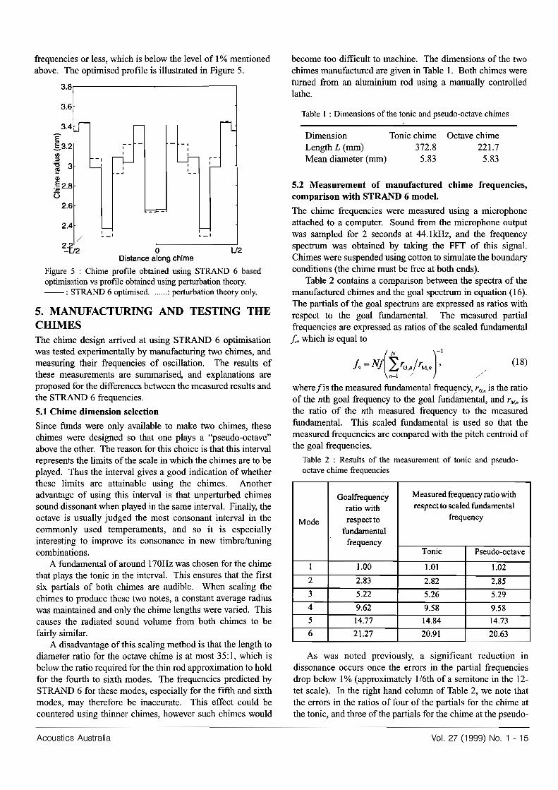
Table 2 contains a comparison between the spectra of the manufactured chimes and the goal spectrum in equation (16) The partials of the goal spectrum are CJ!pressed as ratios with re;-pect to the goal fundamental. The measured panial frequencies are expressed as ratios of the scaled fundam ental j., which is equal to
! .. N!(t'o.J'",f (18)
where/is the mea.,ured fundamental frequc:nq, is the ratio of Ibe nih goal frequency tn the goal fundamental, and r". is the ralio of lhe 11th measured frequency 10 tho measured fundamental. This scaled fundamental is used so that the measured frequencies are compared with the pitch centroid of the goal frequencies.
Table 2 : Results or the mcasU!"CTTICt't or tonic and pseudo-
Goalfrequeocy ratio with respectto""aJedftmdamcntal
rre<[uency
f,equency
5.26 529 9.S8 9,SS 14.84 14.73
20.91 20.63
As was noted pn--viously, a significant reduction in dissonance occurs once the errors in the partial frequencies drop below 1% (approximately 116tb "fa semitone in the 12-tet scale). In the right hand column "fTable 2, "'"e note that the errors in tbe "f f"ur "r the for the chime at the tonic, <Ind three of the partials for the chime at tbe pseudo-
Vol. 27 (1999) NO. 1 - 15
octave, are less than 1%. Thus consonanctl will be improved for at least some of the chords playable in the scale proposed in (15), when comparing chimes manufactured with the STRAND 6 optimised profIle to unperturbed chimes.
There are a number offactors contribnting to the errors in the STRAND 6 predictions of the perturbed chime frequencies. These inclnde differences in segment length and chime radius when comparing the manufactured chimes to the finite element model, and the uneertainty in the location of the measured partials due to the resolution of the recording equipment. These effects, ho-ver, are less important than the cOllllequences of ina.!x:ura.cies in our finite element model. The STRAND 6 simulation used to predict the chime frequencies made use of a thin rod approximation that neglects shear effects, as well as being slightly inaccurate in its treatment of the forees between adjacent cylindrical segments These effects cause our simulation to yield higher frequencies than expected for higher modes, hence the downward trend in the measured frequency ratios when comparing to the goal frcquencyratios
6. CONCLUSION The results obtained in this study are encouraging, since they indicate that the musical performance of designed using the method proposed is perceptibly superior to the perfonnance of unperturbed cylindrical rods, for the stretched Pythagorean scale. Error with respect to the goal spectrum in the partials of the 1lllII1nfactured chimes was mainly due to shear effects not modelled by our finite element simulation, and/or the incorrect assumptions made in this simulation when joining thin beam elements end to end
There are a number of ways to further improve the perfonnance of these chimes. The chimes eould be tuned by hand, or by ehanging the goal frequencies nsed in the finite element optimisation of the profile derived using perturbation theory. Another approach would be to use a more sophisticated finite clement model of the chimes. Alternatively, the chime profile could be designed by perturbing the beam equations [7], which take shear effects into account and do not require a thin beam approximation to hold. This would allow the diameter of the ehimcs to be greatly increased, thus increasing both manufacturabllity and acoustic radiation efficiency. Once a single mch chime has been produced with a slitisfactory spectrum, a set of chimes could easily be manufactured by linearly scaling the length and diameter of the successful design
Perhaps the most exciting outcome of this research is that these chimes represent, to our knowledge, the first attempt at applying Scthares' method [2,3] of creating a ilpectnnn for a musical scale in a non-electronic instrument. Musical imltrument design methods such as the one proposed in this study have the possibility of opening up vast new realms of musical potential to composers. The evolution of these design methods, both for cylindrical chimes and for other non-harmonic instruments, will undoubtedly be a fascinating
16 - Vol. 27 (1999) No.1
REFERENCES [lJ R. Plomp and W. 1. M. Levell, Tonal Consonance andCritical
BandWidth, J. Soc. Am.)fI, 548-560 (1965). [2] W.A. Se\hares, Specifying Spectrn for Scales, 1.
Acoust. Soc. Am. 1112,2422-2431 (1997). [3] W.A. Seihares, Tuning, TImbre, Spectrum, Scale, Springer-
Verlag, New York (!998) SO-54, 211-233. [4] N.H. Fletcher, Tuning a Pentangle _ A New Mu.ical
Vibrating Elemcnt,Applied Acoustics 39, 145-163 (1993). [5] J. Petrolito and K. A. Legge, Optimal undercuts forthe tuning
of percussive beams, 1. Acousl. Soc. Am. 102, 2432-2437 (1997)
[6] N.H. Fletcher, T.D. Rossing, The Physics of Musical 1lI8truments, Springer-verlag, New Ymk(I99I) pp. 5:;-60
[7] F.S. Tse, I.E. Morse, R.T. Hinkle, Mechanical Vibration,,", Theory andApplications, 2nd edition., Allyn ond Bacon inc., BOlItQ!l (1978)pp. 265-271.
[8] IH. William;. Jr, Fundamentals of Applied Dynamics, John Wiley ond Sons Tnc., New York (1996).
[9] S. Kalpakjian, Manufacturing Processes for Engi/leeriJJg Malerials, 2nd edition, Addison WeslcyNew York (1991).
[10] D.L. Logan, A First Course in the Finite Element Method, 2nd edition, PWS Pub. Co., Boston (1993) pp. 324, 265-268.
[II] P.M. MOTIie, Vlbrotian and Sound, 2nd edition, Acoustical Society of America, New York (1981).
[12] M.F. Ashby, O.R.H Jones, Engineering Materials 1, An fntrodw:lion to Iheir Propertie/j and Applicallons, Pcrmagon Press, New York (1<}80) pp. 51-52.
ACOUSTIC & NOISE SPECIALISTS Superb Anechoic and Reverberant Test
Facilities Servicing: • Transmission, Sound Power and Absorption testing
• Residenllal and Environmental Noise • Education and Training • Acoustic Research
126 Grevllle Street, Chatswood, NSW 2067 Phone: (02) 9412 6800