gravitational wave detection using precision interferometry gregory harry massachusetts institute of...
TRANSCRIPT
Gravitational Wave Detection Using Precision Interferometry
Gregory Harry Massachusetts Institute of Technology
- On Behalf of the LIGO Science Collaboration -
July 20, 2004American Society for Precision
Engineering Middletown CT

LIGO-G050323-00-0
Gravitational Wave Detection
L ase r/M C
R ecy clin g M irro r
6 W
1 0 0 W
1 3 k W0 .2 W
In p u t Tes t M irro r
E n d Test M irro r
4 k m F ab ry -P e ro t c a v itie s
W hole Interferom eter Enclosed in Vacuum
• Gravitational waves predicted by Einstein• Accelerating masses create ripples in space-time• Need astronomical sized masses moving near speed of light to get detectable effect
Laser Interferometer Gravitational-wave Observatory
•Two 4 km and one 2 km long interferometers • Two sites in the US, Louisiana and Washington• Similar experiments in Italy, Germany, Japan• Whole optical path enclosed in vacuum• Sensitive to strains around 10-21
LIGO
LIGO-G050323-00-0
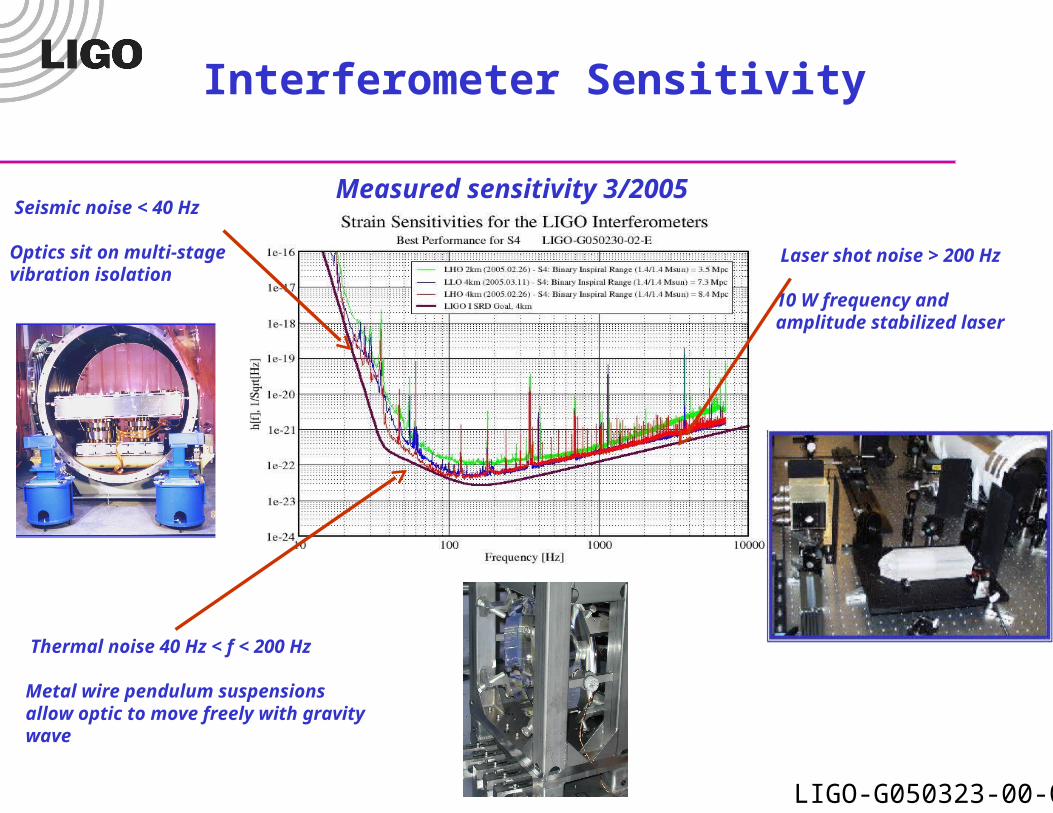
Interferometer Sensitivity
Measured sensitivity 3/2005 Seismic noise < 40 Hz
Optics sit on multi-stage vibration isolation
Thermal noise 40 Hz < f < 200 Hz
Metal wire pendulum suspensions allow optic to move freely with gravity wave
Laser shot noise > 200 Hz
10 W frequency and amplitude stabilized laser

LIGO-G050323-00-0
Advanced LIGO
Total Noise
Total Thermal Noise
Optical Noise
Coating Thermal Noise
Substrate Thermal Noise
Seismic Noise
Proposed Sensitivity • Factor of 15 in strain improvement• Seismic isolation down to 10 Hz• 180 W of laser power• Larger optics with improved coating• Additional mirror for signal recycling
signal recycling mirror
power recycling mirror
Advanced Configuration
Improved coating
silica ribbon
Suspension
LIGO-G050323-00-0
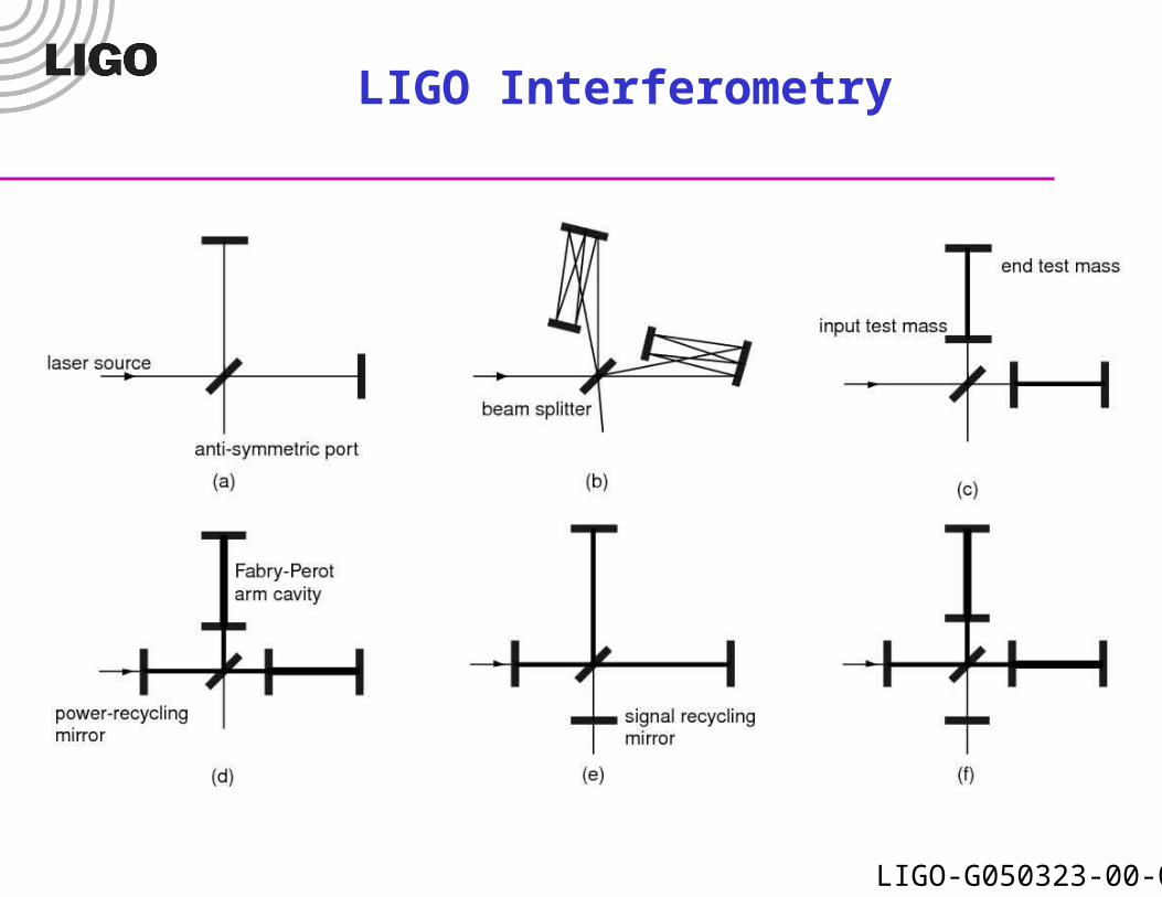
LIGO Interferometry

LIGO-G050323-00-0
Optical Configuration
Some Requirements
Sensitivity ~10-19 m/√Hz (150 Hz)Controller range ~100 µm (tides)Differential arm length ≤10-13 m
rmsIntensity noise ≤10-7/√Hz (150 Hz)Frequency noise ≤3×10⁻⁷ Hz/√Hz
(150 Hz)Angular Control ≤10-8 rad Input beam jitter ≤4×10⁻⁹ rad/√Hz
(150 Hz)
LIGO-G050323-00-0
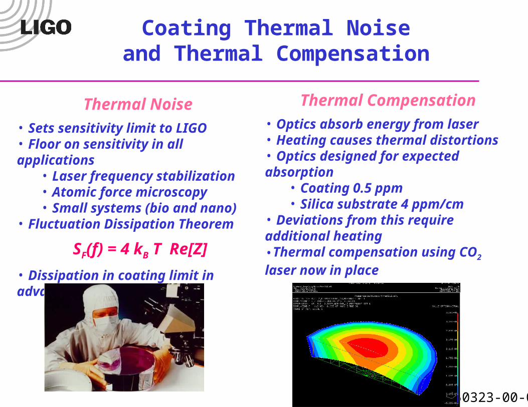
Coating Thermal Noise and Thermal Compensation
Thermal Noise • Sets sensitivity limit to LIGO• Floor on sensitivity in all applications
• Laser frequency stabilization• Atomic force microscopy• Small systems (bio and nano)
• Fluctuation Dissipation Theorem
SF(f) = 4 kB T Re[Z]
• Dissipation in coating limit in advanced LIGO
Thermal Compensation• Optics absorb energy from laser• Heating causes thermal distortions• Optics designed for expected absorption
• Coating 0.5 ppm• Silica substrate 4 ppm/cm
• Deviations from this require additional heating•Thermal compensation using CO2 laser now in place

LIGO-G050323-00-0
Coating Research
Optical AbsorptionPhotothermal Common-Path
Interferometry• Can measure sub-ppm absorption• Spatial resolution sub-millimeter
Mechanical LossPredicts thermal noise
Measure modal Q’s
Model elastic energy distribution
LIGO-G050323-00-0
Silica/Tantala Coatings
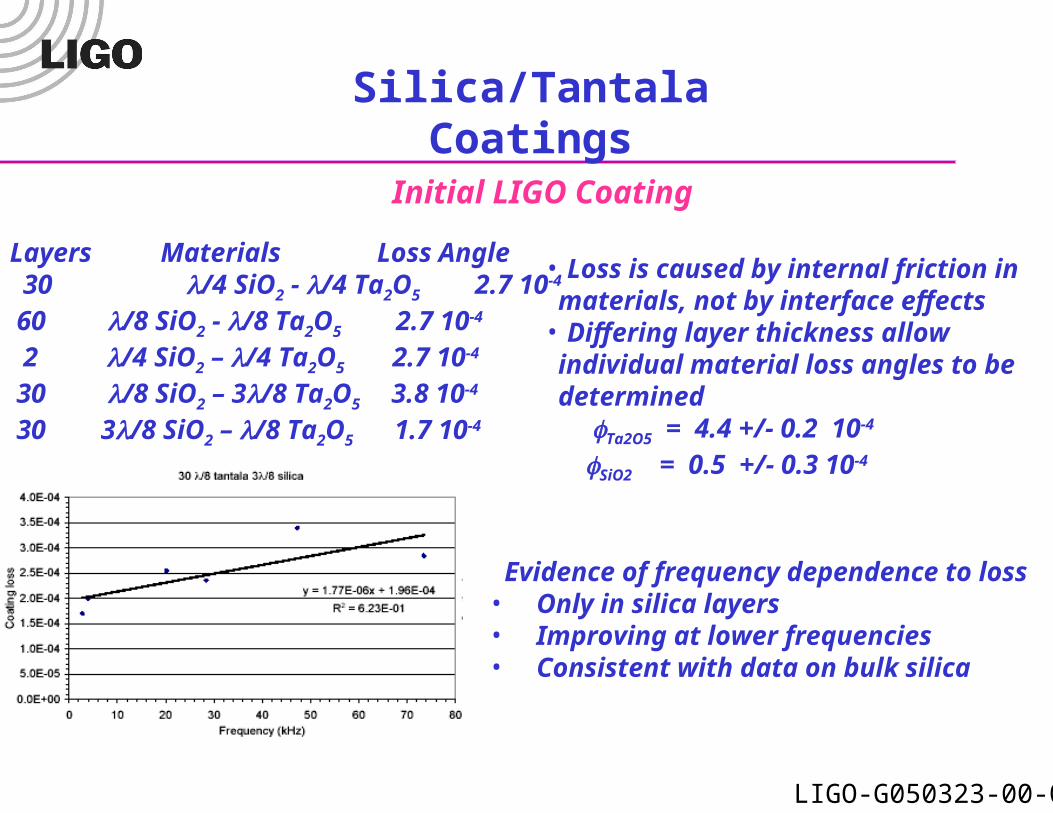
Layers Materials Loss Angle30/4 SiO2 - /4 Ta2O5 2.7 10-4
60 /8 SiO2 - /8 Ta2O5 2.7 10-4
2 /4 SiO2 – /4 Ta2O5 2.7 10-4
30 /8 SiO2 – 3/8 Ta2O5 3.8 10-4
30 3/8 SiO2 – /8 Ta2O5 1.7 10-4
Evidence of frequency dependence to loss• Only in silica layers• Improving at lower frequencies• Consistent with data on bulk silica
• Loss is caused by internal friction in materials, not by interface effects• Differing layer thickness allow individual material loss angles to be determined
Ta2O5 = 4.4 +/- 0.2 10-4 SiO2 = 0.5 +/- 0.3 10-4
Initial LIGO Coating
LIGO-G050323-00-0
0 10 20 30 40 50 60
1.5
2
2.5
3x 10⁻⁴
Relative Concentration
Loss
Ang
le
Small CoaterLarge Coater
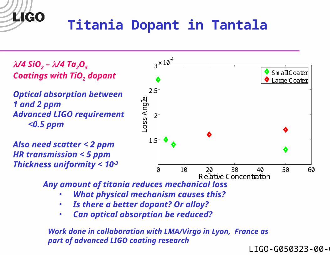
Titania Dopant in Tantala
/4 SiO2 – /4 Ta2O5 Coatings with TiO2 dopant
Work done in collaboration with LMA/Virgo in Lyon, France aspart of advanced LIGO coating research
Any amount of titania reduces mechanical loss • What physical mechanism causes this?• Is there a better dopant? Or alloy?• Can optical absorption be reduced?
Optical absorption between 1 and 2 ppm Advanced LIGO requirement
<0.5 ppm
Also need scatter < 2 ppmHR transmission < 5 ppmThickness uniformity < 10-3

LIGO-G050323-00-0
Absorption in LIGO Optics
0.02 0.04 0.06 0.08 0.1 0.120
0.02
0.04
0.06
0.08
0.1
radius (m)
de
pth
(m
)
Temnperature Profile for 1 Watt Coating Absorbtion
1
2
3
4
5
6
Laser light reflecting off coatings and traversing silica substrates will be absorbed.
Largest effect in input mirrors because of the transmission
Heating and lensing cause reduction in interference pattern and power buildup
Coating absorption
0.02 0.04 0.06 0.08 0.1 0.120
0.02
0.04
0.06
0.08
0.1
radius (m)
de
pth
(m
)Temnperature Profile for 1 Watt Substrate Absorbtion
1
1.5
2
2.5
Substrate absorption

LIGO-G050323-00-0
Thermal Compensation
CO2 Laser
?Over-heat mask Under-heat mask Inhomogeneous mask
ZnSe Viewport
Over-heat pattern
Under-heat pattern
Raw Heating pattern
Heating and lensing controlled by adding additional heat with a CO2 laser
Too much heating can be corrected by adding light to optic edge
Too little heating can be corrected by adding light to center
May have to correct for inhomogeneous heating in advanced LIGO

LIGO-G050323-00-0
Sensitivity Improvement from Thermal Compensation
Lensing was bad enough at Hanford 4 kilometer interferometer could not operate above 4 W of input power
With thermal compensation, high power and less shot noise are achievable
Advanced LIGO will have nearly 1 MW of circulating power in cavities
Low absorption coatings and substrates, as well as high performance thermal compensation, are essential
Green: without thermal compensationRed: with thermal compensation

LIGO-G050323-00-0
Conclusions
• Gravitational wave detection is pushing the limits of interferometric sensing
• LIGO is close to achieving sensitivity goal
• Planned advanced LIGO will improve on initial interferometers
• Coating thermal noise will be limiting noise source in future interferometers
• Thermal lensing requires compensation system

LIGO-G050323-00-0
Optics Metrology
Initial LIGO • Surface figure rms< 0.8 nm over central 80 mm
• Repeatable to 0.2 nm• Radius of curvature
• Match between optics in same arm to 1.5 %• Repeatability to 5 nm
• Measured using Fizeau interferometry Difference in consecutive cavity measurements
LIGO-G050323-00-0
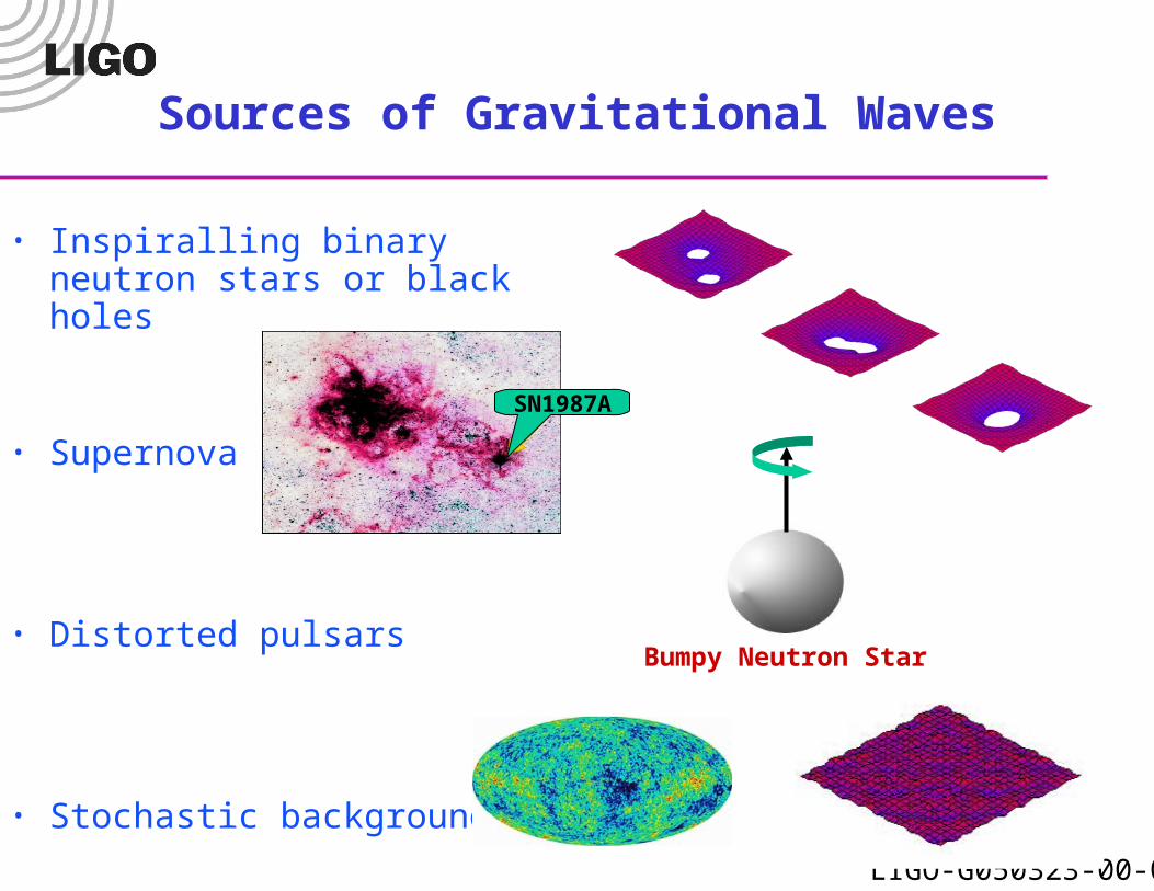
Sources of Gravitational Waves
• Inspiralling binary neutron stars or black holes
• Supernova
• Distorted pulsars
• Stochastic background
SN1987A
Bumpy Neutron Star

LIGO-G050323-00-0
Direct Measurement of Coating Thermal Noise
• LIGO/Caltech’s Thermal Noise Interferometer• 1 cm long arm cavities, 0.15 mm laser spot size• Consistent with ~ 4 10-4 coating loss angle
Measured Noise
Laser Shot Noise
Coating Thermal Noise