gps mobile tracker user manual - electia ab · 6 2. general description the tracker can be operated...
TRANSCRIPT
GPS MOBILE TRACKER
USER MANUAL
22
Table of Contents
1 General Instruction1.1 Precaution before installation 1.3 Mounting and release of the unit 31.2 Battery Charging 1.4 Install SIM Card and battery
2 General Descriptions 62.1 Data format of SMS messages 2.7 Stationary or on the Move2.2 SOS function 2.8 Motion Sensor2.3 Line-In and Line-Out 2.9 Extra GPS & GSM ant. connections2.4 Geofence feature 2.10 No GPS Data2.5 Car Battery connection 2.11 Recall History data2.6 Battery LOW level 2.12 Last Valid GPS position data
3 Operation Mode Instructions 73.1 Direct commands 3.2.1 Motion Sensor mode3.1.1 Single GPS mode 3.2.2 Geofence mode3.1.2 Track mode 3.2.3 Power Saving mode3.1.3 Last Valid GPS coordinates 3.2.4 Line-Outputs3.2 On-OFF Commands Modes/Functions 3.2.5 Switch Off Track mode
4 Initialization / Programming modes 94.1 Password (Security Code) 4.5 SOS Phone number setting4.2 GPS Data Format 4.6 Geofence4.3 Tracking mode 4.7 Default Mode4.4 Tel. mode (overriding caller ID)
5 Recall modes to retrieve system data 115.1 GPS Data format settings 5.4 Geofence Settings5.2 Tracking mode settings 5.5 SOS Phone numbers5.3 Tel. mode(overriding caller ID)
6 Geofence 12GEOfence mode description
7 Line-Inputs 137.1 Absolute Mode 7.2 Relative Mode
8 Line-Outputs 14
9 Timing criteria 15
10 Track Mode 18
11 GPS accuracy and time to Fix and SMS delays 19
12 Examples how to enter the coordinates into internet Map programs 2012.1 Google Maps (Satellite Images) 12.3 MapQuest12.2 Google Maps
13 GSM World Coverage Map 22
14 Quick demo to get acquainted with the Product 23
15 General Command - string overview 24
16 Command and Instruction List for SMS messages 25
17 GPRS FUNCTION GUIDE 29
33
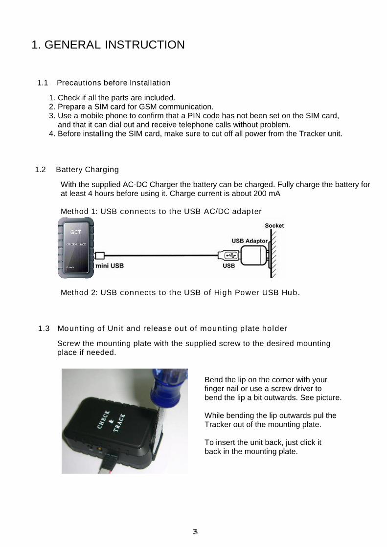
1. GENERAL INSTRUCTION
1.1 Precautions before Installation
1. Check if all the parts are included.2. Prepare a SIM card for GSM communication.3. Use a mobile phone to confirm that a PIN code has not been set on the SIM card,
and that it can dial out and receive telephone calls without problem.4. Before installing the SIM card, make sure to cut off all power from the Tracker unit.
1.2 Battery Charging
With the supplied AC-DC Charger the battery can be charged. Fully charge the battery forat least 4 hours before using it. Charge current is about 200 mA
Method 1: USB connects to the USB AC/DC adapter
Method 2: USB connects to the USB of High Power USB Hub.
1.3 Mounting of Unit and release out of mounting plate holder
Screw the mounting plate with the supplied screw to the desired mountingplace if needed.
Bend the lip on the corner with yourfinger nail or use a screw driver tobend the lip a bit outwards. See picture.
While bending the lip outwards pul theTracker out of the mounting plate.
To insert the unit back, just click itback in the mounting plate.

4
1.4 Install SIM Card and battery:
1. Remove the back cover of your tracker, as illustrated above.2. Unscrew the screw and push the battery cover (with an ellipse indent) rightward
to remove it. (Fig.1)3. Push the top of the SIM card holder as indicated by the green arrow. (Fig.2)
Fig. 1 Fig. 2
4. Move the holder upwards as indicated by the red arrow. (Fig.3)5. Insert the SIM card by sliding it into the card holder slot, with the chip module
facing to the connectors, as shown in the picture (Fig. 4)
Fig. 3 Fig. 4
5
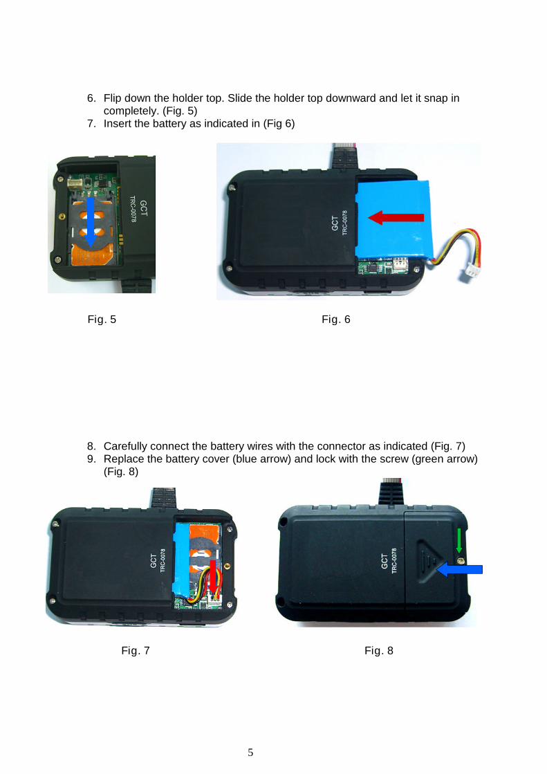
6. Flip down the holder top. Slide the holder top downward and let it snap incompletely. (Fig. 5)
7. Insert the battery as indicated in (Fig 6)
Fig. 5 Fig. 6
8. Carefully connect the battery wires with the connector as indicated (Fig. 7)9. Replace the battery cover (blue arrow) and lock with the screw (green arrow)
(Fig. 8)
Fig. 7 Fig. 8

6
2. General Description
The Tracker can be operated by standard SMS messages, or via GPRS. Via an SMS,the GPS position data can be requested and will be sent back to the requested party’smobile phone via an SMS. The number and the time sequence of these GPS datablocks and other parameters are fully programmable by an instruction SMS.
2.1 Data Format of SMS Command Messages:
The data has to comply with an exact format able to be read by the tracker module.The format is: [Password]-[mode]-[Sub-Group1]-[Sub-Group2]
Password : Factory default password is 1234Mode : Select the operating mode. This can be a Direct command,
Set-up command, or a Recall command.Sub-Group1 : ON / OFF commands; or Set-up (Initialization) or Request group.Sub-Group2 : Parameters of the set-up group. Information like Telephone
numbers, setting string of T and C mode, data format for GPSinformation (DMS,Google,Ddec) etc.
2.2 SOS function:
When the SOS button is pressed, the position data will be sent to a preset phonenumber(s). Maximum 8 numbers can be stored which all will be notified if a SOS situationoccurs. These phone numbers can be set via a SMS message sent to the tracker unit.
2.3 Line-In and Line-Out: (Only applicable for TRC0078)
This tracker has 4 Line-inputs, of which 2 can be used to detect switch positions. Theother 2 can be used for relative values such as temperature or fuel level. Via the Out-putlines remote equipment can be activated like an Alarm or immobilizer
2.4 Geo-Fence feature:
This tracker has a geo-fence feature. If activated, the instructed party will receive a SMSwhen the Tracker unit exits set boundary area.
2.5 Car Battery connection: (TRC0078 only)
This tracker has a built-in DC-DC converter to allow to be connected to the 12-24V carbattery. This circuitry is special design to meet the ISO 7637 requirements
2.6 Battery Low alert:
When the Internal battery is nearly empty and reaches a certain voltage level the chargeLED starts blinking and later an SMS message will be sent to indicate “Battery Low”
2.7 Stationary or on the move: (TRE0078 only)
In “Tracking” mode; if the position data equals the 4 previous transmitted positions (to beretrieved from SMS 4), the “Tracking” mode will stop, a SMS message will be sent withextra info in the SMS message “Stationary Position”.
2.8 Motion sensor:
The tracker has a motion sensor and when switched ON the tracker will automaticallyswitch to Track Mode when acceleration is detected twice within 30 sec to 1 minute.
7
2.9 Extra GPS and GSM antenna connections: (TRC0078 only)
The tracker has extra antenna sockets to allow connection to external antennas. Internalcircuitry automatic detects and delivers the power supply to the external antenna (GPS).
2.10 No GPS data:
If no GPS data can be retrieved from the GPS receiver the unit will transmit the currentGSM tower location “Node” information.
2.11 Recall history data: (TRE0078 only)
A total of 8 previously transmitted SMS messages which contain position data can berecalled via SMS request.
2.12 Last valid GPS position data:
The “LAST” valid GPS position data can be recalled via SMS message.
3. Operation and Command Modes :
3.1 Direct Commands
3.1.1 Single GPS request mode [S]
Command string: [Security code]-[S] example: 1234-S
In the single GPS request mode only the present GPS information will be sent or if no
GPS data is available the GSM “node” info will be sent to requested phone number via
SMS.
3.1.2 Tracking mode [T]
Command string: [Security code]-[T] example: 1234-T
The Tracking mode is intended to regularly check the position of the unit automatically
where regular update of position is required, for example, when tracking a stolen vehicle.
The SMS information includes:
GPS coordinates, GPS date and GPS time.
3.1.3 LAST valid GPS coordinates [LAST]
Command string: [Security code]-[LAST] example: 1234-LAST
Incase no GPS data can be transmitted (No satellite reception) the GSM cell phone tower
“Node” information will be sent. With the “LAST” command however, it is possible to
retrieve the last valid GPS coordinates which could possibly still be more accurate than the
“Node” information.
8
3.2 ON / OFF Commands for Modes & Functions
3.2.1 Motion sensor mode [M]
Command string: [Security code]-[M]-[on] example: 1234-M-on
When required, the motion sensor can be switched ON. It will then automatically set the
Tracker into the Track-Mode if movement is detected twice within 30sec-1minute. The
Motion sensor can be switched OFF again via command:
[Security code]-[M]-[off]
3.2.2 Geo-Fence mode [GEO]
Command string: [Security code]-[GEO]-[on] example: 1234-GEO-on
The Geo-fence feature allows the user to set a virtual boundary. The tracker will inform the
user when leaving this boundary. The radius of this boundary (circle) is set in default to
100 meters. The Geo-Fence mode van be switched off via command:
[Security code]-[GEO]-[off]
3.2.3 Power Saving mode [PS]
Command string: [Security code]-[PS]-[off] example: 1234-PS-off
The Power Save mode (PS) allows extended operation of the tracker without recharging
the battery. Battery life however depends on the uses of the various functions. The default
setting for Power Save is OFF. If Power Save is switched ON, and the unit is only
powered from the internal battery, it will be switched off for the user-defined (“C”) periods
and will not respond to new SMS commands in those time intervals.
The Power Save mode can be switched on with command:[Security code]-[PS]-[on]
3.2.4 Line-Output [LO] (TRC0078 only)
Command string: [Security code]-[Lox]-[on] example: 1234-LOX-on (X =1 or 2)
To activate the Line-Out, the above command has to be sent. Without (X) it will activate
both output lines. They can be switched off with command:[Security code]-[LOx]-[off]
3.2.5 TRACK mode [T]
Command string: [Security code]-[T] example: 1234-T
To switch on the Track mode when you automatically want regular position updates
The Track mode can be switched OFF with command:
[Security code]-[T]-[off] example: 1234-T-off
9
4. Initialization / Programming mode (I)
4.1 Password (Security code)
A password is required to operate the Tracker properly and allow the tracker to accept theSMS commands. The factory default password is “1234”. It is important to change thepassword to one of your own choice (max 8 alpha-numeric characters). Do not forgetyour password, because it can only be re-set again to the default by the factory. Tochange this number the following command has to be sent via SMS:
Password-I-SEC-new (α-numeric) security number
For example, if you want to change the password from the default “1234” to “4321”, thenyou will have send the following SMS to the device: 1234-I-Sec-4321
A SMS will be sent to the caller ID to reconfirm the new setting
4.2 GPS DATA FORMAT
The default GPS data format is in Degrees minutes and seconds. Another format can beselected, like a data format in Degrees decimal. To change the default setting thefollowing command string has to be sent via SMS:
Password-I-GPS-DMS means Data in Degrees, minutes and secondsPassword-I-GPS-Google means URL link for Google MapsPassword-I-GPS-Ddec means Data in Degrees, decimalPassword-I-GPS-NMEA-xxxxx means a complete line of the NMEA data.
Available lines for xxxxx are:GPGGA = Global position Fix dataGPRMC = Recommended minimum data sentenceGPGSA = Overall satellite status data.
A SMS will be sent to the caller ID to reconfirm the new setting
4.3 TRACKING MODE
In Tracking mode the tracker will send the GPS information every 3 minutes (Defaultsetting is T=0003) and will repeat this 20 times (R=020). Furthermore the time betweenchecking for new incoming SMS messages is 10 min (C=010). Track-Mode is normallyused, for example, in a chase situation when a car is stolen and continuous tracking of theroute is important. To enter new time (T) number of repeats (R) and SMS check time (C)the following command has to be sent:
Password-I-TRK-TxxxxRxxxCxxx Example: 1234-I-TRK-T0003R020C010
A SMS will be sent to the caller ID to reconfirm the new setting.
NOTE: The time to check for new incoming SMS messages (C) applies when the unit isoperating from the internal battery only, and Power save mode is active, with no externalpower connected to it. If connected to a car battery (for example), then the unit will bepermanently ready to receive a new incoming SMS message, thus the “C” time will notapply.
Restrictions: SMS checks C within the time T x R will only be carried out if T>2CSee NOTE at the end of this section for expanded information.

10
4.4 TEL MODE (Overriding caller ID)
The Tracker can be instructed to send the SMS messages to other telephone number thanthe caller ID telephone number of the mobile phone from which the original set-upinformation or request for information was sent. This can be useful in, for example, aroaming situation where the callers ID is not always correctly presented or where the calleris running out of battery power and would like to switch over to another mobile phone. Thetracker can be instructed to override the default mode to SMS back to a specifiedtelephone number by sending the following string:
Password-I-TEL-xxxxxxxxxxx xxxxxxxxxxx= <+><country code><phone number>
Any subsequent instruction sent to the tracker will override this setting and return to usethe caller ID telephone number, the only exception is the command: Password-R-TEL
4.5 SOS PHONE NUMBERS
To enter SOS phone number(s)(max 8) the following string has to be sent via SMS:
Password-I-SOS#-xxxxxxxxx xxxxxxxxx= IDD phone number max 16 digits incl. +
SOS1 is the 1st SOS IDD number, SOS2 is 2nd etc. A SMS will be sent to the caller ID toreconfirm each new setting and to the new SOS number a SMS will be sent with text info.
“You will receive GPS coordinates in case of emergency”To erase a phone number, just send: Password-I-SOS#-0
4.6 GEOFENCE MODE
The geofence mode creates a virtual circular boundary around the unit’s location. Theradius of this circle can be set by the following command:
Password-I-GEOxx xx is the radius x 100m. (For TRE0078 xxx)
For example, “GEO01”, means 100m. This is also the default radius.(Or GEO001 for TRE0078 which has a 3 digit input)
A confirmation SMS will be sent to indicate the settings.
4.7 DEFAULT MODE
The unit can be set to all the original default settings, except the password, with command:
Password-I-D
A SMS will be sent to the caller ID to reconfirm the default settings.

11
5. Recall mode (To review system data)
5.1 GPS DATA FORMAT
A command can be sent to the tracker to ask for the instructed GPS data formatinformation. Command for this info request is:
Password-R-GPS
A SMS will be sent with GPS data (DMS, Ddec or other)
5.2 TRACKING MODE Settings
A command can be sent to the tracker to reveal the last set “Track” Mode parametersT , R and C. Command structure of the “Track” mode settings request is:
Password-R-TRK
A SMS will be sent to indicate the set parameters of time between GPS transmission (T),number of repeats (R) and SMS check time (C). Example: TRK :T0003R020C010
5.3 TEL MODE (Overriding caller ID)
Request for telephone number where SMS messages will be sent. This can be the callerID or the new instructed Phone number where the GPS data has to be sent to. Commandstructure for “TEL” request is: Password-R-TEL
5.4 GEOFENCE Setting
Request for Radius of Geofence circle. Command structure of the “Geo” request is:
Password-R-GEO
A SMS will be sent to indicate the Geo-fence radius in meters.
5.5 SOS PHONE NUMBERS
A command can be sent to the tracker to reveal the last set SOS phone numbers.Command structure of the SOS phone numbers request is:
Password-R-SOSx
Where X is position number of the stored SOS phone number.SOS1 means phone number of SOS1. SOS2 means phone number of SOS2, and so on.
5.6 MOTION SENSOR Setting
To find out if the Motion Sensor is ON or OFF, the following command can be sent:
Password-R-M
A SMS will be sent to reveal if the Motion sensor is switched ON, or OFF.

12
6. Geofence
Goefence is a virtual circular boundary of which the radius can be set by SMScommand. This feature allows the user to observe if the Tracker will remain within a setboundary (area) or if it will leave this area. This can be important for asset or vehiclemonitoring with limited allowed access within a specified region. Also useful, forexample, for the elderly with dementia problems when living in an elderly home.
When the Geofence is switched ON it will take the tracker’s position at that moment todraw a virtual circle with a specified radius. In default this radius is 100 meter.The command to switch the Geofence On is:
Password-GEO-ON example: 1234-GEO-ON orPassword-GEO-OFF example: 1234-GEO-OFF to switch the geofence off.
To set a different boundary for example with radius of 400 m:
Password-I-GEO04
DEFAULT SETTING:When no Geofence range is set the tracker will use the default setting of 100 meter.Any other range can be set via the following command:
[security code]-[I]-[GEOXX] example 1234-I-GEO07
Where XX is a 2-digit figure and represents the radius of the circle in multiples of 100meter. Example GEO07 = 700 meters, or Geo10 = 1000 meters.
STOPPING GEOFENCE:To turn off the Geofence mode, the following command (SMS message) has to be sentto the Tracker:
[security code]-[GEO]-[off] example 1234-GEO-off
To check the Geofence setting, aSMS message has to be sent to thetracker as follows:
Password-R-GEO
The tracker will send SMS with therequested information.
Example:“GEOFENCE is set to 400m”
13
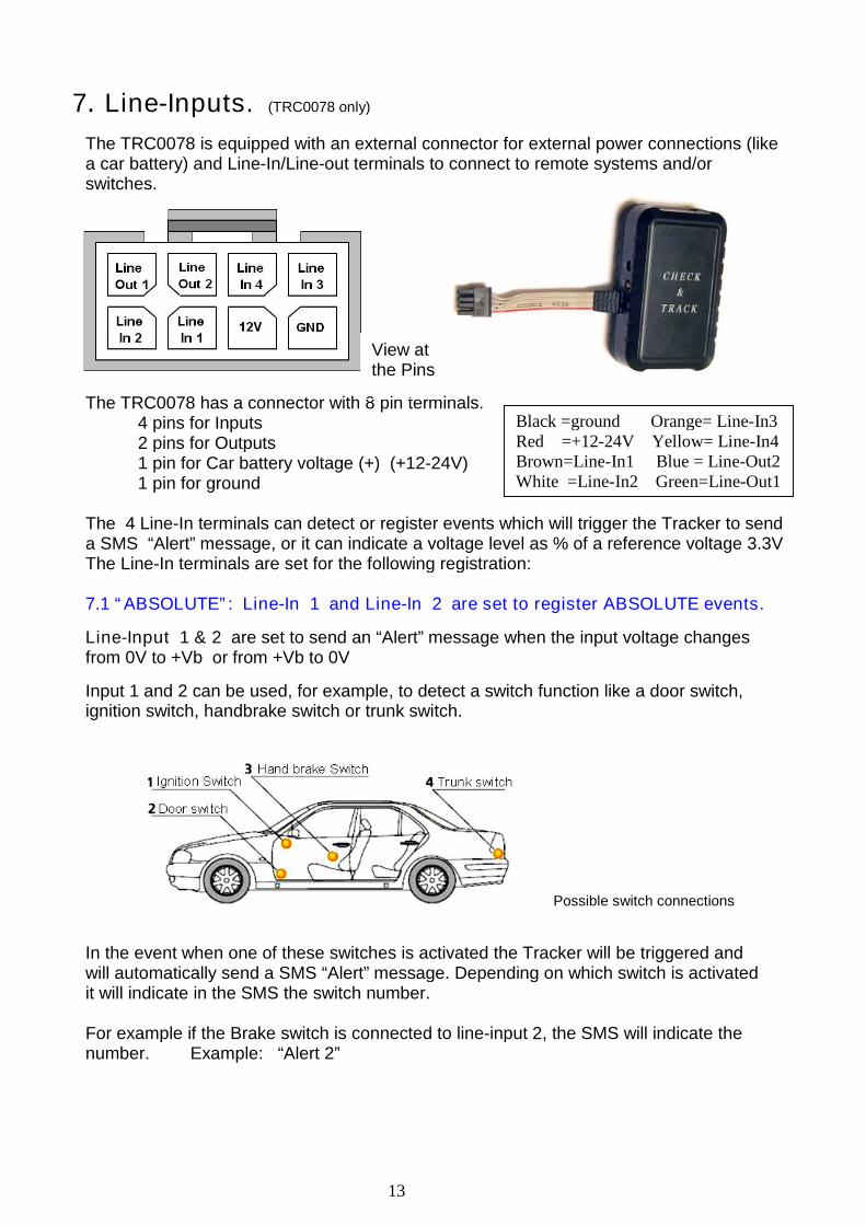
7. Line-Inputs. (TRC0078 only)
The TRC0078 is equipped with an external connector for external power connections (likea car battery) and Line-In/Line-out terminals to connect to remote systems and/orswitches.
The TRC0078 has a connector with 8 pin terminals.4 pins for Inputs2 pins for Outputs1 pin for Car battery voltage (+) (+12-24V)1 pin for ground
The 4 Line-In terminals can detect or register events which will trigger the Tracker to senda SMS “Alert” message, or it can indicate a voltage level as % of a reference voltage 3.3VThe Line-In terminals are set for the following registration:
7.1 “ABSOLUTE”: Line-In 1 and Line-In 2 are set to register ABSOLUTE events.
Line-Input 1 & 2 are set to send an “Alert” message when the input voltage changesfrom 0V to +Vb or from +Vb to 0V
Input 1 and 2 can be used, for example, to detect a switch function like a door switch,ignition switch, handbrake switch or trunk switch.
Possible switch connections
In the event when one of these switches is activated the Tracker will be triggered andwill automatically send a SMS “Alert” message. Depending on which switch is activatedit will indicate in the SMS the switch number.
For example if the Brake switch is connected to line-input 2, the SMS will indicate thenumber. Example: “Alert 2”
View atthe Pins
Black =ground Orange= Line-In3Red =+12-24V Yellow= Line-In4Brown=Line-In1 Blue = Line-Out2White =Line-In2 Green=Line-Out1
14
7.2 “RELATIVE”: Line-In 3 and 4 are set to register RELATIVE events.
Both inputs measure the input voltage via an A/D converter and register the voltage levelas % of a reference voltage of 3.3V.
In the Relative mode it is possible to measure fluctuating parameters and the delta ofthese fluctuations, like Temperature or Fuel Levels. If for example the input voltage is1.32 volt the SMS message will indicate: Li3= 40%.
The Line-Input status is indicated in each GPS coordinate message.
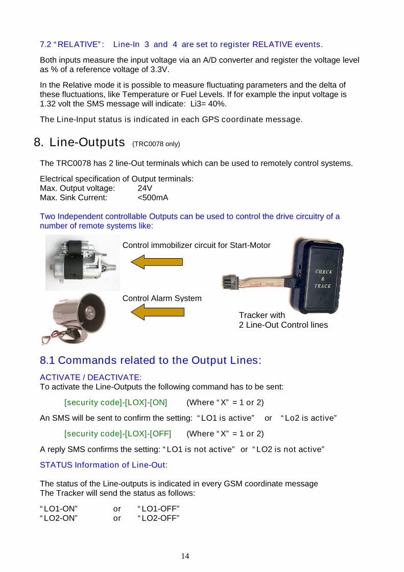
8. Line-Outputs (TRC0078 only)
The TRC0078 has 2 line-Out terminals which can be used to remotely control systems.
Electrical specification of Output terminals:Max. Output voltage: 24VMax. Sink Current: <500mA
Two Independent controllable Outputs can be used to control the drive circuitry of anumber of remote systems like:
8.1 Commands related to the Output Lines:
ACTIVATE / DEACTIVATE:To activate the Line-Outputs the following command has to be sent:
[security code]-[LOX]-[ON] (Where “X” = 1 or 2)
An SMS will be sent to confirm the setting: “LO1 is active” or “Lo2 is active”
[security code]-[LOX]-[OFF] (Where “X” = 1 or 2)
A reply SMS confirms the setting: “LO1 is not active” or “LO2 is not active”
STATUS Information of Line-Out:
The status of the Line-outputs is indicated in every GSM coordinate messageThe Tracker will send the status as follows:
“LO1-ON” or “LO1-OFF”“LO2-ON” or “LO2-OFF”
Control immobilizer circuit for Start-Motor
Control Alarm System
Tracker with2 Line-Out Control lines
15
9. Timing criteria
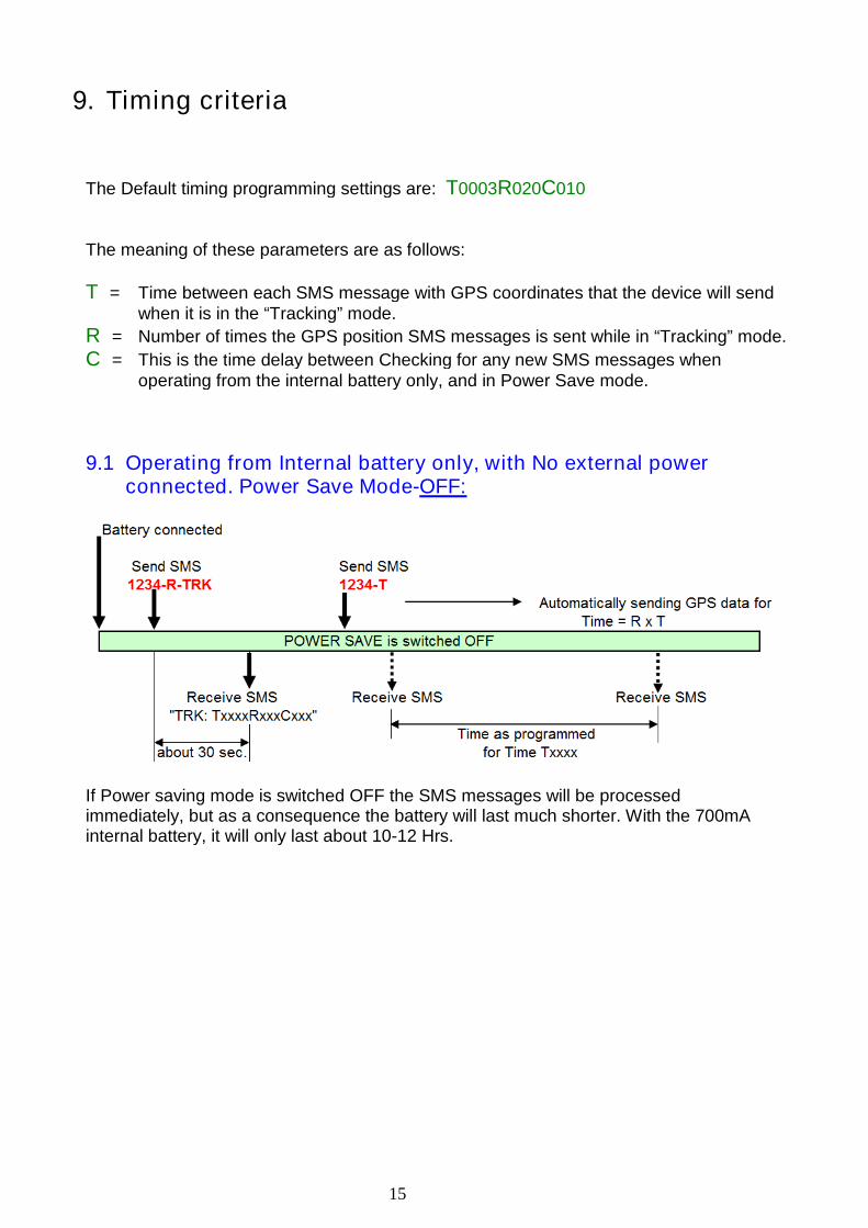
The Default timing programming settings are: T0003R020C010
The meaning of these parameters are as follows:
T = Time between each SMS message with GPS coordinates that the device will sendwhen it is in the “Tracking” mode.
R = Number of times the GPS position SMS messages is sent while in “Tracking” mode.
C = This is the time delay between Checking for any new SMS messages whenoperating from the internal battery only, and in Power Save mode.
9.1 Operating from Internal battery only, with No external powerconnected. Power Save Mode-OFF:
If Power saving mode is switched OFF the SMS messages will be processedimmediately, but as a consequence the battery will last much shorter. With the 700mAinternal battery, it will only last about 10-12 Hrs.
16
NOTE: Expanded information on Parameter settings for Tracking andPower Save modes:
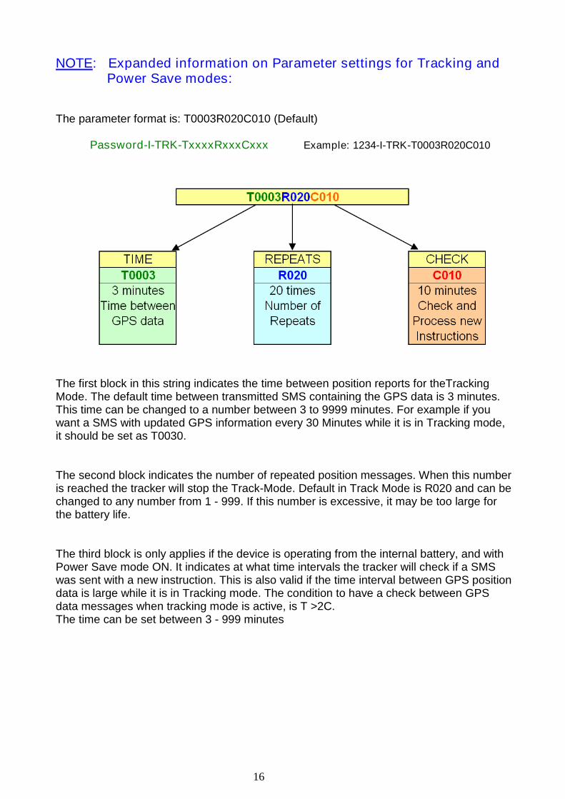
The parameter format is: T0003R020C010 (Default)
Password-I-TRK-TxxxxRxxxCxxx Example: 1234-I-TRK-T0003R020C010
The first block in this string indicates the time between position reports for theTrackingMode. The default time between transmitted SMS containing the GPS data is 3 minutes.This time can be changed to a number between 3 to 9999 minutes. For example if youwant a SMS with updated GPS information every 30 Minutes while it is in Tracking mode,it should be set as T0030.
The second block indicates the number of repeated position messages. When this numberis reached the tracker will stop the Track-Mode. Default in Track Mode is R020 and can bechanged to any number from 1 - 999. If this number is excessive, it may be too large forthe battery life.
The third block is only applies if the device is operating from the internal battery, and withPower Save mode ON. It indicates at what time intervals the tracker will check if a SMSwas sent with a new instruction. This is also valid if the time interval between GPS positiondata is large while it is in Tracking mode. The condition to have a check between GPSdata messages when tracking mode is active, is T >2C.The time can be set between 3 - 999 minutes

17
9.2 Power Save Mode-ON. Operating from internal battery only, withNO external power connected:
In above example a message 1234-R-TRK is sent in the active Time (about 1.5 min.) ofthe Tracker and a response message will normally be received in about 30 seconds.(Depending on the mobile network provider)
The second SMS command 1234-T can only be processed in the next active time afterthe Power Save period, and the entire device is turned off for 10 minute periods (Orwhatever the “C” time is required by the user).
NOTE: If the “T” time in the Track mode is set to <10 min the tracker will be able toreceive instruction SMS messages directly for the time T x R. If time is >10 min thetracker will go into Power Savings (PS) and a SMS sent in that period will only beprocessed after the check time “C” is finished. See example above.
NOTE: Before switching to PS mode ON it is advised to run the tracker in PS - modeOFF for about 15 minutes to allow the tracker to build-up the Ephemeris and Almanac ofthe satellites and after all new parameters are changed to your preferred settings.
NOTE: For a general idea of how Power saving mode saves battery life, when a SMS issent with GPS coordinates every 15 min (e.g. Tracking mode activated with a “T” time of15 min), the internal battery will last about one week. Depending on other parametersettings the battery life could even last for months.
9.3 External power connected with Power Save Mode-ON: (TRC0078 only)
The device will be able to receive SMS messages at all times, and they will beprocessed immediately while within the GSM reception area. Other features, like theinternal GPS, goes into standby mode to save the battery power of the external powersource. It will be activated by the required mode you want to pre-program. Example –Motion sensor ON and Power save ON: The tracker will be able to receive SMScommands at all times, but will only switch on the GPS when motion is detected, orwhen you request GPS position.
NOTE: It is important to note that there is a difference in how the Power Save featureworks, depending on if it is connected to an external power source, or if it is onlyoperating from the internal battery. If connected to an external power source, the devicewill be able to receive new SMS commands at all times. In other words, the “C” timing isnot valid at all, as the GSM feature remains permanently active in this case.
If operating ONLY from the internal battery, then the device will not be able to receivenew SMS commands while it is in standby during the “C” times programmed if PowerSave is ON.
18
10. Track Mode
Command String: <Password>-T for Track Mode example: 1234-T
The Track Mode is important in cases where a regular position check is important, forexample, when your vehicle is stolen and you want to track its route. Track mode is alsoactivated by the Motion sensor, or by geofencing if required.
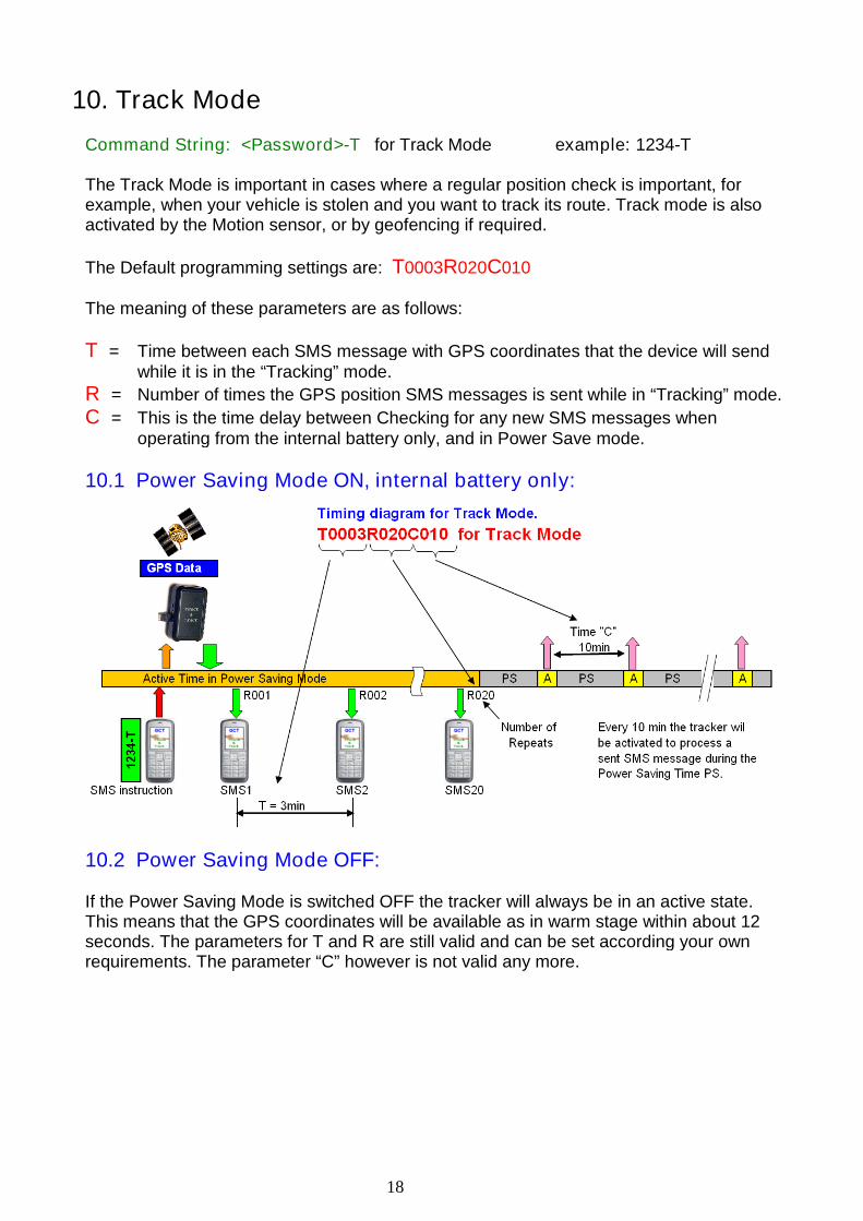
The Default programming settings are: T0003R020C010
The meaning of these parameters are as follows:
T = Time between each SMS message with GPS coordinates that the device will sendwhile it is in the “Tracking” mode.
R = Number of times the GPS position SMS messages is sent while in “Tracking” mode.
C = This is the time delay between Checking for any new SMS messages whenoperating from the internal battery only, and in Power Save mode.
10.1 Power Saving Mode ON, internal battery only:
10.2 Power Saving Mode OFF:
If the Power Saving Mode is switched OFF the tracker will always be in an active state.This means that the GPS coordinates will be available as in warm stage within about 12seconds. The parameters for T and R are still valid and can be set according your ownrequirements. The parameter “C” however is not valid any more.

19
11. GPS accuracy and time to Fix and SMS Delays
11.1 Accuracy
Place the tracker in a position to allow the best possible open sky view. Obstruction canaffect the time and accuracy of the GPS data. The accuracy of the GPS positiondepends on a number of factors. First of all, the number of satellites from which signalscan be received by the tracker. More satellites will give a better accuracy. The numberof the satellites received is an important factor.
1- Better Accuracy 2 - Less accurate
Further more, a clear sky view will give better results than a sky view which isobstructed by buildings and/or trees. Accuracy according reception of signals as shownin picture 1 can sometimes be within a few meters.
11.2 Time to Fix, Time of acquisition of GPS data
Apart from the points listed under 11.1, the time of a 2D or 3D fix depends on thereceived signal strength of the satellites. It is therefore important not to put obstaclesbetween the tracker and the open sky. For example, a thick jacket over the tracker willinfluence the sensitivity and will result in longer times to acquire the satellite data. Innormal operation condition the time for 3D Fix is around 40 seconds(Cold start) andbetween 6-20 sec. in a “warm” start condition.
11.3 Time delays due to GSM Network congestion
Depending on the GSM network traffic, SMS instructions and/or data transfer can bevery quick. However, due to heavy traffic congestion these messages can sometimesbe delayed. It is recommended if this kind of delay happens to wait for awhile beforeresending a SMS message.
It is strongly recommended to use SIM cards in your mobile phone and tracker from thesame telephone company to avoid latency in the SMS handling. Messages betweendifferent network providers are handled differently and can sometimes cause excessivedelays. When very long latencies occur please contact the supplier for special settingsto minimize this problem
20
12. Examples on how to put the coordinates in a Map program
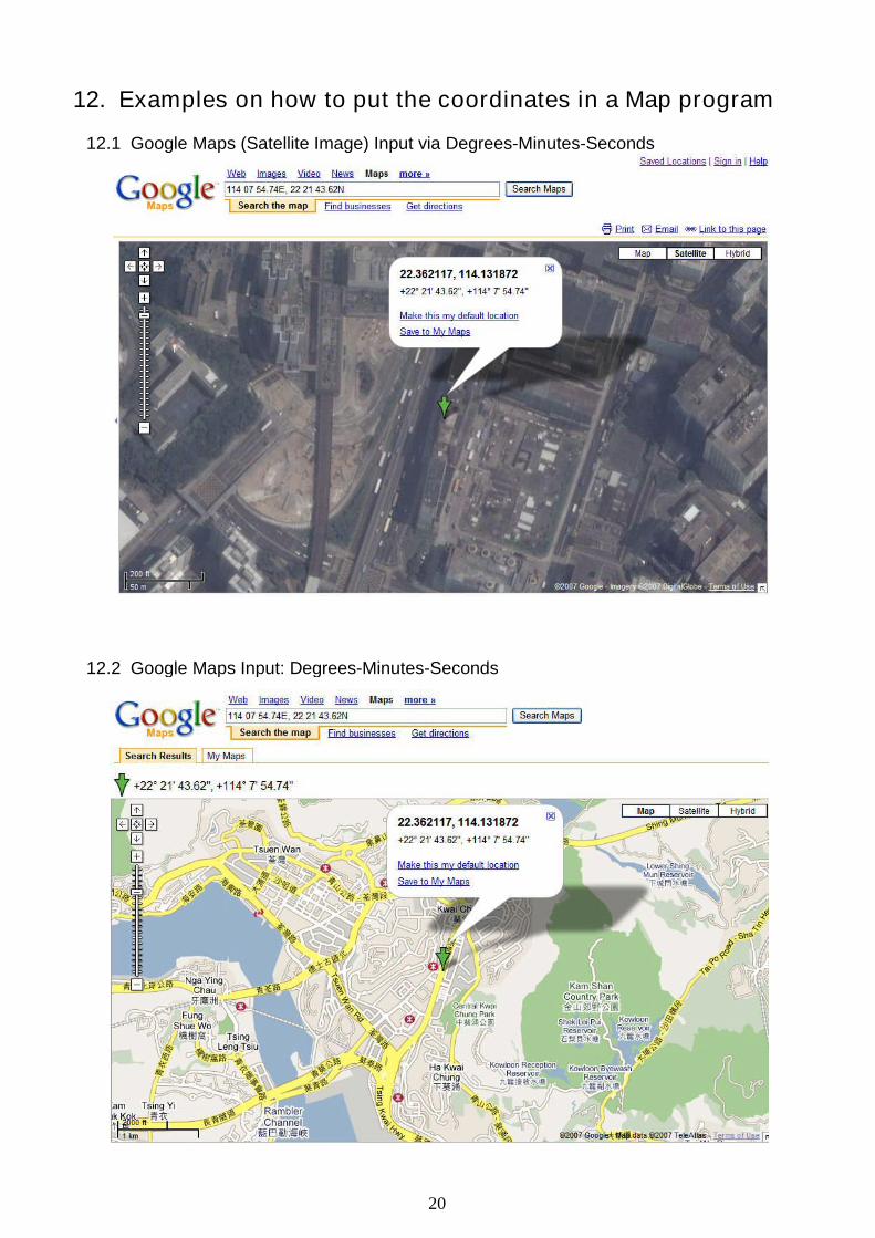
12.1 Google Maps (Satellite Image) Input via Degrees-Minutes-Seconds
12.2 Google Maps Input: Degrees-Minutes-Seconds
21
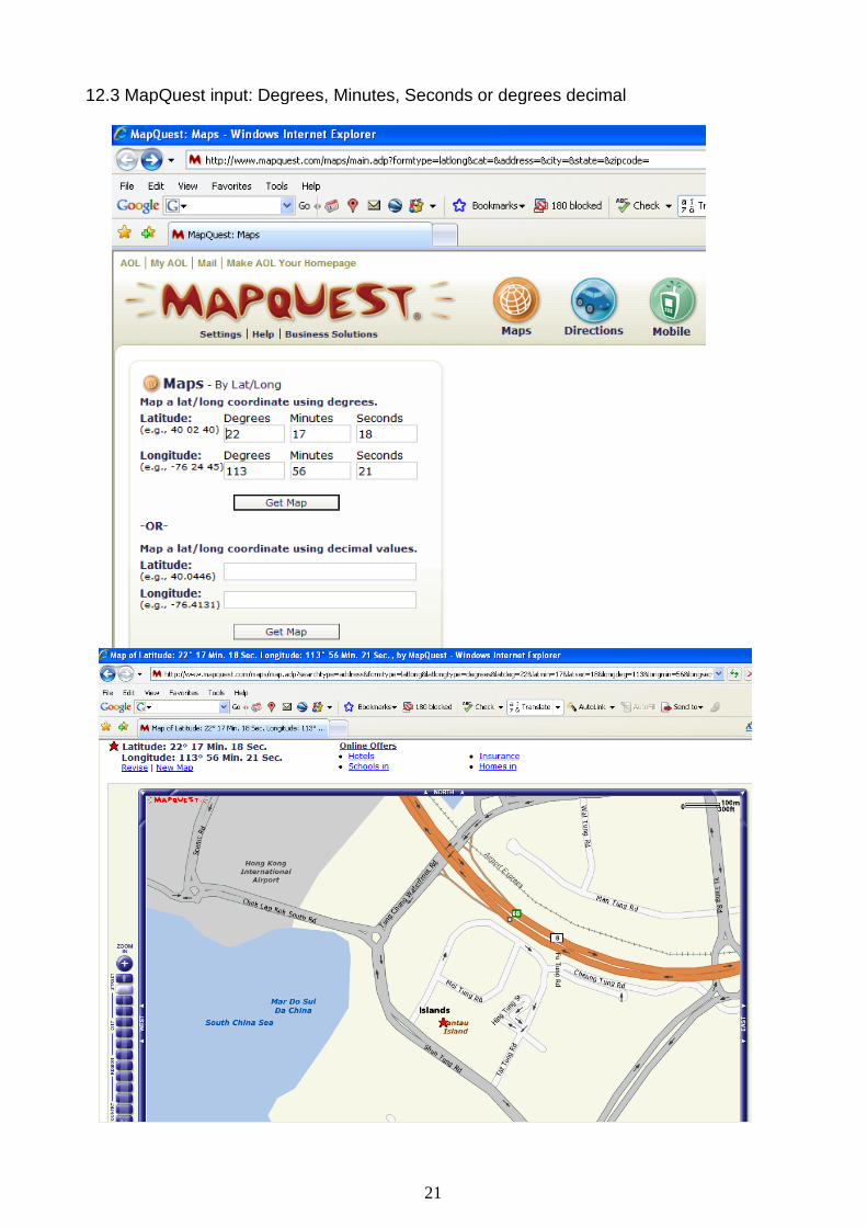
12.3 MapQuest input: Degrees, Minutes, Seconds or degrees decimal

22
13. GSM Coverage of the World
Trackers with a GSM telephone module can only be used in GSM covered area’s.
23
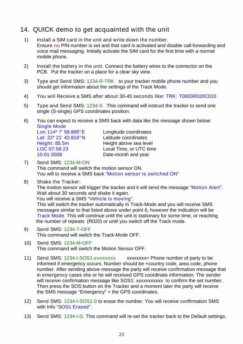
14. QUICK demo to get acquainted with the unit
1) Install a SIM card in the unit and write down the number.Ensure no PIN number is set and that card is activated and disable call-forwarding andvoice mail messaging. Initially activate the SIM card for the first time with a normalmobile phone.
2) Install the battery in the unit. Connect the battery wires to the connector on thePCB. Put the tracker on a place for a clear sky view.
3) Type and Send SMS: 1234-R-TRK to your tracker mobile phone number and youshould get information about the settings of the Track Mode.
4) You will Receive a SMS after about 30-45 seconds like: TRK: T0003R020C010
5) Type and Send SMS: 1234-S This command will instruct the tracker to send onesingle (S-single) GPS coordinates position.
6) You can expect to receive a SMS back with data like the message shown below:Single ModeLon 114* 7’ 58.895”E Longitude coordinatesLat: 22* 21’ 42.816”N Latitude coordinatesHeight: 85.5m Height above sea levelLOC 07:58:23 Local Time, or UTC time10-01-2008 Date-month and year
7) Send SMS: 1234-M-ONThis command will switch the motion sensor ON.You will to receive a SMS back “Motion sensor is switched ON”
8) Shake the Tracker:The motion sensor will trigger the tracker and it will send the message “Motion Alert”.Wait about 30 seconds and shake it again.You will receive a SMS “Vehicle is moving”.This will switch the tracker automatically in Track-Mode and you will receive SMSmessages similar to that listed above under point 6, however the indication will beTrack Mode. This will continue until the unit is stationary for some time, or reachingthe number of repeats (R020) or until you switch off the Track mode.
9) Send SMS: 1234-T-OFFThis command will switch the Track-Mode OFF.
10) Send SMS: 1234-M-OFFThis command will switch the Motion Sensor OFF.
11) Send SMS: 1234-I-SOS1-xxxxxxxx xxxxxxxx= Phone number of party to beinformed if emergency occurs. Number should be +country code, area code, phonenumber. After sending above message the party will receive confirmation message thatin emergency cases she or he will received GPS coordinate information. The senderwill receive confirmation message like SOS1: xxxxxxxxxxx to confirm the set number.Then press the SOS button on the Tracker and a moment later the party will receivethe SMS message “Emergency” + the GPS coordinates.
12) Send SMS: 1234-I-SOS1-0 to erase the number. You will receive confirmation SMSwith Info “SOS1 Erased”.
13) Send SMS: 1234-I-D. This command will re-set the tracker back to the Default settings.
24
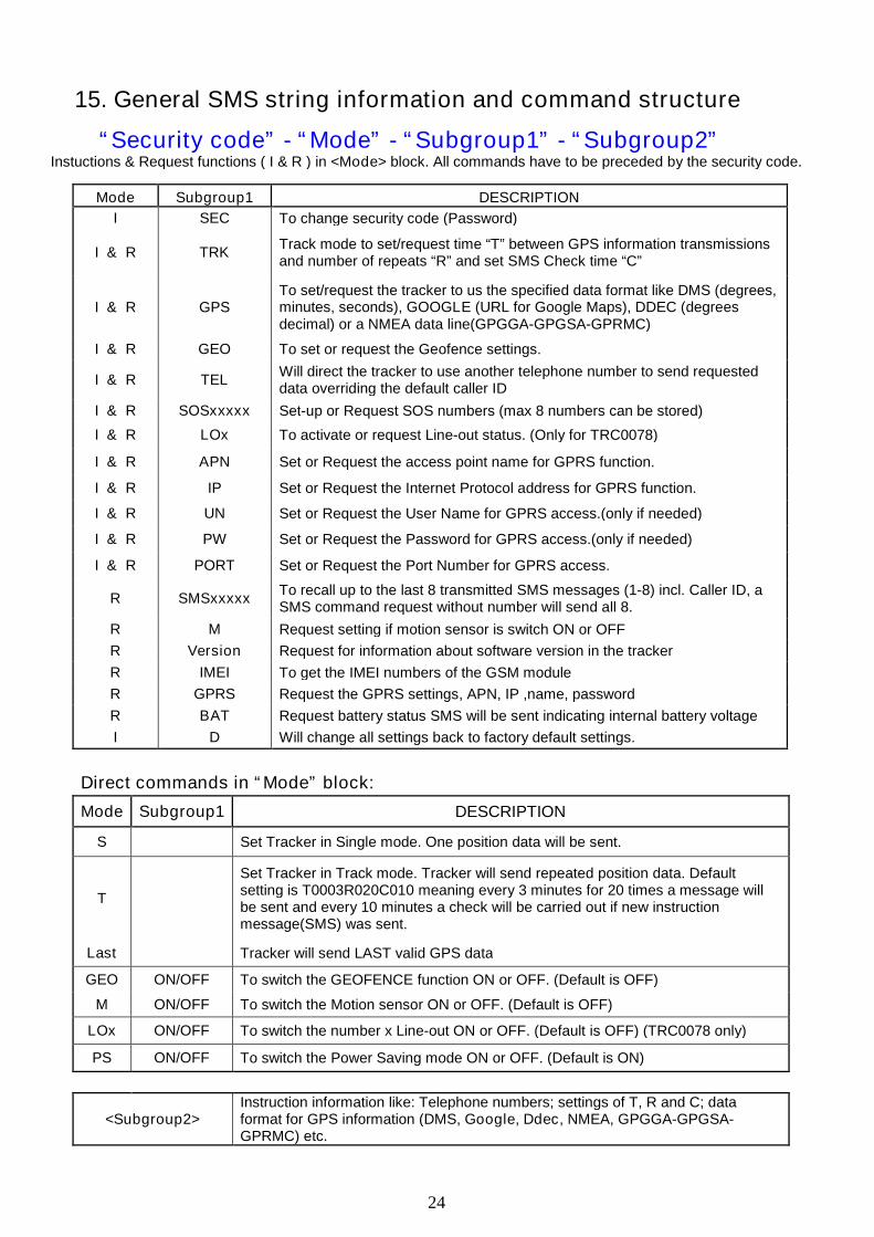
15. General SMS string information and command structure
“Security code” - “Mode” - “Subgroup1” - “Subgroup2”Instuctions & Request functions ( I & R ) in <Mode> block. All commands have to be preceded by the security code.
Mode Subgroup1 DESCRIPTION
I SEC To change security code (Password)
I & R TRKTrack mode to set/request time “T” between GPS information transmissionsand number of repeats “R” and set SMS Check time “C”
I & R GPSTo set/request the tracker to us the specified data format like DMS (degrees,minutes, seconds), GOOGLE (URL for Google Maps), DDEC (degreesdecimal) or a NMEA data line(GPGGA-GPGSA-GPRMC)
I & R GEO To set or request the Geofence settings.
I & R TELWill direct the tracker to use another telephone number to send requesteddata overriding the default caller ID
I & R SOSxxxxx Set-up or Request SOS numbers (max 8 numbers can be stored)
I & R LOx To activate or request Line-out status. (Only for TRC0078)
I & R APN Set or Request the access point name for GPRS function.
I & R IP Set or Request the Internet Protocol address for GPRS function.
I & R UN Set or Request the User Name for GPRS access.(only if needed)
I & R PW Set or Request the Password for GPRS access.(only if needed)
I & R PORT Set or Request the Port Number for GPRS access.
R SMSxxxxxTo recall up to the last 8 transmitted SMS messages (1-8) incl. Caller ID, aSMS command request without number will send all 8.
R M Request setting if motion sensor is switch ON or OFF
R Version Request for information about software version in the tracker
R IMEI To get the IMEI numbers of the GSM module
R GPRS Request the GPRS settings, APN, IP ,name, password
R BAT Request battery status SMS will be sent indicating internal battery voltage
I D Will change all settings back to factory default settings.
Direct commands in “Mode” block:
Mode Subgroup1 DESCRIPTION
S Set Tracker in Single mode. One position data will be sent.
T
Set Tracker in Track mode. Tracker will send repeated position data. Defaultsetting is T0003R020C010 meaning every 3 minutes for 20 times a message willbe sent and every 10 minutes a check will be carried out if new instructionmessage(SMS) was sent.
Last Tracker will send LAST valid GPS data
GEO ON/OFF To switch the GEOFENCE function ON or OFF. (Default is OFF)
M ON/OFF To switch the Motion sensor ON or OFF. (Default is OFF)
LOx ON/OFF To switch the number x Line-out ON or OFF. (Default is OFF) (TRC0078 only)
PS ON/OFF To switch the Power Saving mode ON or OFF. (Default is ON)
<Subgroup2>Instruction information like: Telephone numbers; settings of T, R and C; dataformat for GPS information (DMS, Google, Ddec, NMEA, GPGGA-GPGSA-GPRMC) etc.
25
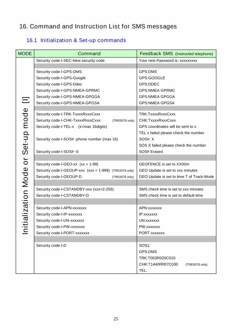
16. Command and Instruction List for SMS messages
16.1 Initialization & Set-up commands
MODE Command Feedback SMS (Instructed telephone)
Security code-I-SEC-New security code Your new Password is: xxxxxxxxx
Security code-I-GPS-DMS GPS:DMS
Security code-I-GPS-Google GPS:GOOGLE
Security code-I-GPS-Ddec GPS:DDEC
Security code-I-GPS-NMEA-GPRMC GPS:NMEA GPRMC
Security code-I-GPS-NMEA-GPGGA GPS:NMEA GPGGA
Security code-I-GPS-NMEA-GPGSA GPS:NMEA GPGSA
Security code-I-TRK-TxxxxRxxxCxxx TRK:TxxxxRxxxCxxx
Security code-I-CHK-TxxxxRxxxCxxx (TRE0078 only) CHK:TxxxxRxxxCxxx
Security code-I-TEL-x (x=max 16digits) GPS coordinates will be sent to x
TEL x failed please check the number
Security code-I-SOS# -phone number (max 16) SOS#: X
SOS X failed please check the number
Security code-I-SOS# -0 SOS# Erased
Security code-I-GEO-xx (xx = 1-99) GEOFENCE is set to XX00m
Security code-I-GEOUP-xxx (xxx = 1-999) (TRE0078 only) GEO Update is set to xxx minutes
Security code-I-GEOUP-D (TRE0078 only) GEO Update is set to time T of Track-Mode
Security code-I-CSTANDBY-xxx (xxx=2-255) SMS check time is set to xxx minutes
Security code-I-CSTANDBY-D SMS check time is set to default time
Security code-I-APN-xxxxxxx APN:xxxxxxx
Security code-I-IP-xxxxxxx IP:xxxxxxx
Security code-I-UN-xxxxxxx UN:xxxxxxx
Security code-I-PW-xxxxxxx PW:xxxxxxx
Security code-I-PORT-xxxxxxx PORT:xxxxxxx
Security code-I-D SOS1:
GPS:DMS
TRK:T003R020C010
CHK:T1440R007C030 (TRE0078 only)
Init
ializa
tio
nM
od
eo
rS
et-
up
mo
de
[I]
TEL:
26
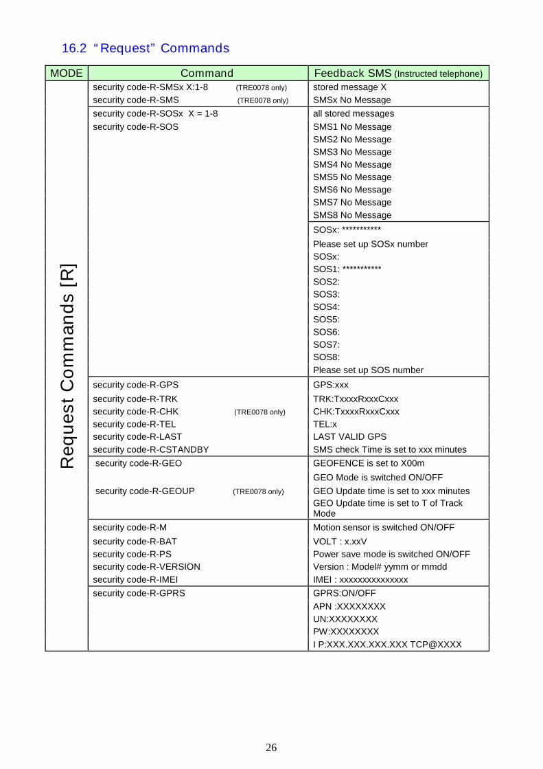
16.2 “Request” Commands
MODE Command Feedback SMS (Instructed telephone)
security code-R-SMSx X:1-8 (TRE0078 only) stored message X
security code-R-SMS (TRE0078 only) SMSx No Message
security code-R-SOSx X = 1-8 all stored messages
security code-R-SOS SMS1 No Message
SMS2 No Message
SMS3 No Message
SMS4 No Message
SMS5 No Message
SMS6 No Message
SMS7 No Message
SMS8 No Message
SOSx: ***********
Please set up SOSx number
SOSx:
SOS1: ***********
SOS2:
SOS3:
SOS4:
SOS5:
SOS6:
SOS7:
SOS8:
Please set up SOS number
security code-R-GPS GPS:xxx
security code-R-TRK TRK:TxxxxRxxxCxxx
security code-R-CHK (TRE0078 only) CHK:TxxxxRxxxCxxx
security code-R-TEL TEL:x
security code-R-LAST LAST VALID GPS
security code-R-CSTANDBY SMS check Time is set to xxx minutes
security code-R-GEO GEOFENCE is set to X00m
GEO Mode is switched ON/OFF
security code-R-GEOUP (TRE0078 only) GEO Update time is set to xxx minutes
GEO Update time is set to T of TrackMode
security code-R-M Motion sensor is switched ON/OFF
security code-R-BAT VOLT : x.xxV
security code-R-PS Power save mode is switched ON/OFF
security code-R-VERSION Version : Model# yymm or mmdd
security code-R-IMEI IMEI : xxxxxxxxxxxxxxx
security code-R-GPRS GPRS:ON/OFF
APN :XXXXXXXX
UN:XXXXXXXX
PW:XXXXXXXX
Re
qu
es
tC
om
ma
nd
s[R
]
I P:XXX.XXX.XXX.XXX TCP@XXXX
27
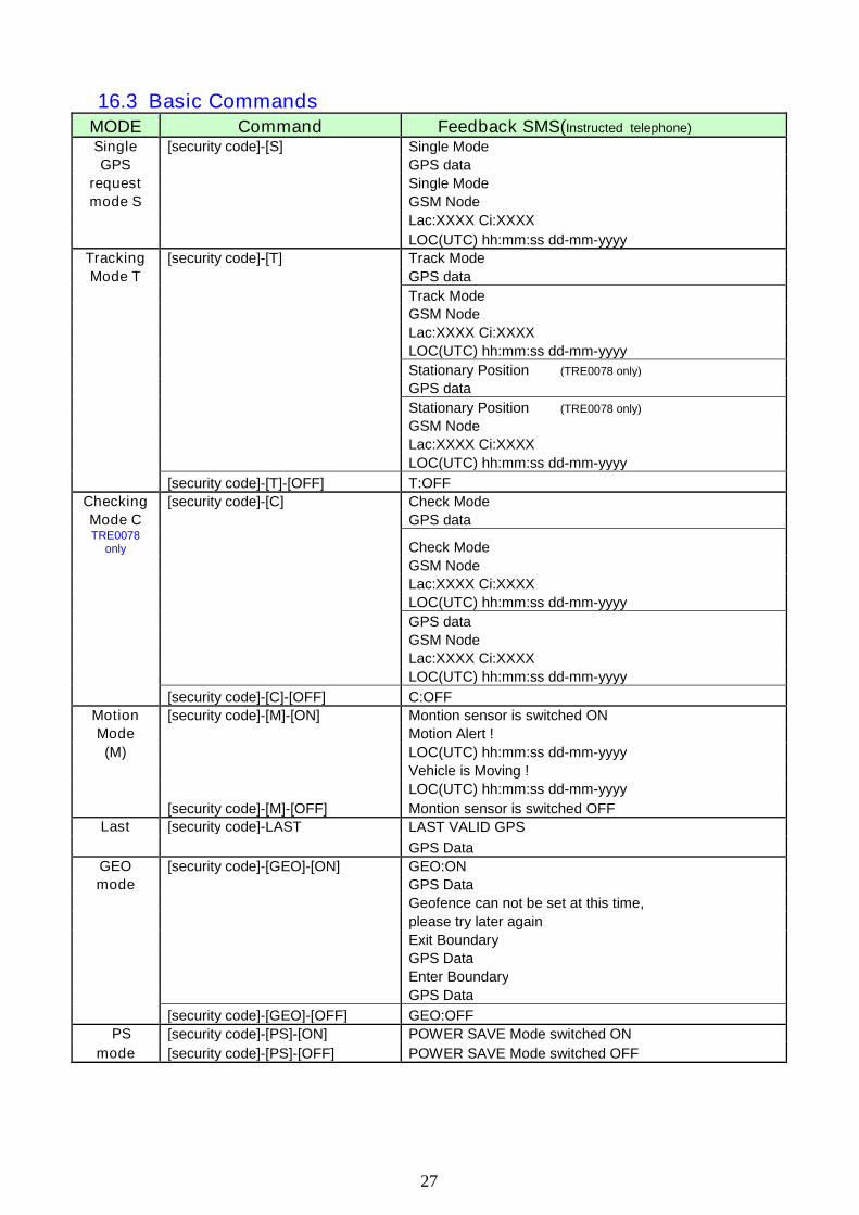
16.3 Basic CommandsMODE Command Feedback SMS(Instructed telephone)
Single [security code]-[S] Single Mode
GPS GPS data
request Single Mode
mode S GSM Node
Lac:XXXX Ci:XXXX
LOC(UTC) hh:mm:ss dd-mm-yyyy
Tracking [security code]-[T] Track Mode
Mode T GPS data
Track Mode
GSM Node
Lac:XXXX Ci:XXXX
LOC(UTC) hh:mm:ss dd-mm-yyyy
Stationary Position (TRE0078 only)
GPS data
Stationary Position (TRE0078 only)
GSM Node
Lac:XXXX Ci:XXXX
LOC(UTC) hh:mm:ss dd-mm-yyyy
[security code]-[T]-[OFF] T:OFF
Checking [security code]-[C] Check Mode
Mode C GPS dataTRE0078
only Check Mode
GSM Node
Lac:XXXX Ci:XXXX
LOC(UTC) hh:mm:ss dd-mm-yyyy
GPS data
GSM Node
Lac:XXXX Ci:XXXX
LOC(UTC) hh:mm:ss dd-mm-yyyy
[security code]-[C]-[OFF] C:OFF
Motion [security code]-[M]-[ON] Montion sensor is switched ON
Mode Motion Alert !
(M) LOC(UTC) hh:mm:ss dd-mm-yyyy
Vehicle is Moving !
LOC(UTC) hh:mm:ss dd-mm-yyyy
[security code]-[M]-[OFF] Montion sensor is switched OFF
LAST VALID GPSLast [security code]-LAST
GPS Data
GEO [security code]-[GEO]-[ON] GEO:ON
mode GPS Data
Geofence can not be set at this time,
please try later again
Exit Boundary
GPS Data
Enter Boundary
GPS Data
[security code]-[GEO]-[OFF] GEO:OFF
PS [security code]-[PS]-[ON] POWER SAVE Mode switched ON
mode [security code]-[PS]-[OFF] POWER SAVE Mode switched OFF
28
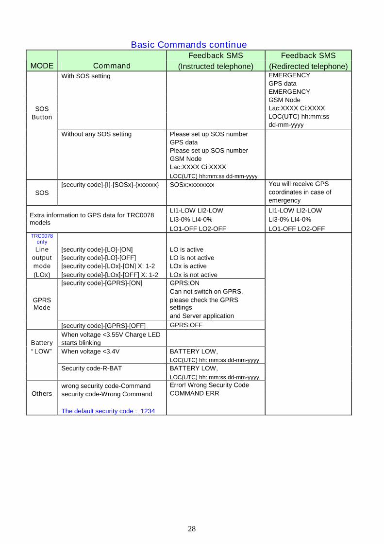
Basic Commands continueFeedback SMS Feedback SMS
MODE Command (Instructed telephone) (Redirected telephone)With SOS setting EMERGENCY
GPS data
EMERGENCY
GSM Node
SOS Lac:XXXX Ci:XXXX
Button LOC(UTC) hh:mm:ss
dd-mm-yyyy
Without any SOS setting Please set up SOS number
GPS data
Please set up SOS number
GSM Node
Lac:XXXX Ci:XXXX
LOC(UTC) hh:mm:ss dd-mm-yyyy
[security code]-[I]-[SOSx]-{xxxxxx} SOSx:xxxxxxxx You will receive GPS
SOS coordinates in case of
emergency
LI1-LOW LI2-LOW LI1-LOW LI2-LOW
LI3-0% LI4-0% LI3-0% LI4-0%Extra information to GPS data for TRC0078models
LO1-OFF LO2-OFF LO1-OFF LO2-OFFTRC0078
only
Line [security code]-[LO]-[ON] LO is active
output [security code]-[LO]-[OFF] LO is not active
mode [security code]-[LOx]-[ON] X: 1-2 LOx is active
(LOx) [security code]-[LOx]-[OFF] X: 1-2 LOx is not active
[security code]-[GPRS]-[ON] GPRS:ON
Can not switch on GPRS,
please check the GPRSsettings
and Server application
GPRSMode
[security code]-[GPRS]-[OFF] GPRS:OFF
When voltage <3.55V Charge LED
Battery starts blinking
“LOW” When voltage <3.4V BATTERY LOW,
LOC(UTC) hh: mm:ss dd-mm-yyyy
Security code-R-BAT BATTERY LOW,
LOC(UTC) hh: mm:ss dd-mm-yyyy
wrong security code-Command Error! Wrong Security Code
Others security code-Wrong Command COMMAND ERR
The default security code : 1234
29
17. GPRS FUNCTION GUIDE (Advanced feature)
Please make sure that there is a PC with public IP address which the user can access theinternet. Also please confirm the SIM card installed in the GPS tracker has GPRS capability.
17.1 Software update
If needed, update the latest software supported to GPS Tracker by USB update tool(USB programming tool.exe).
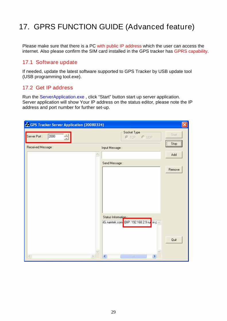
17.2 Get IP address
Run the ServerApplication.exe , click “Start” button start up server application.Server application will show Your IP address on the status editor, please note the IPaddress and port number for further set-up.
30
17.3 GPS Tracker configuration for GPRS
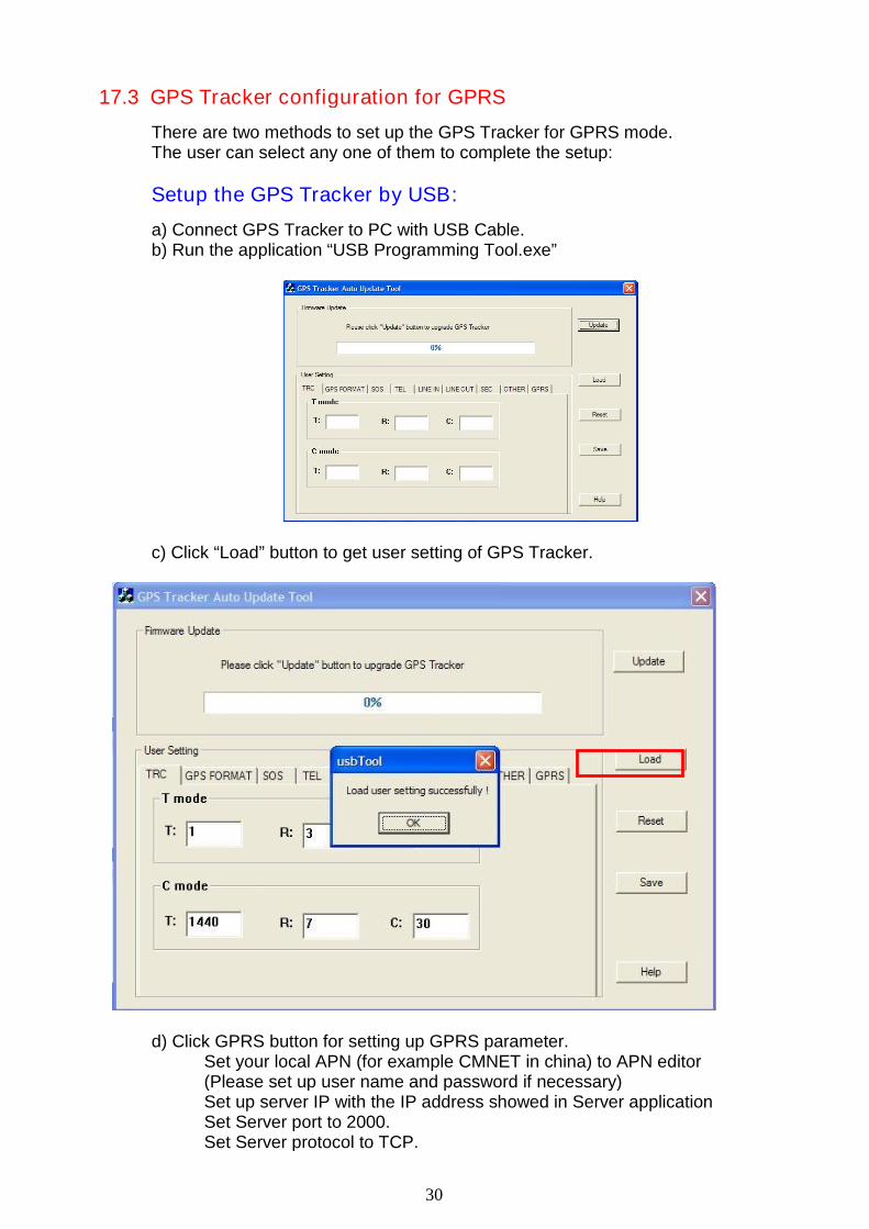
There are two methods to set up the GPS Tracker for GPRS mode.The user can select any one of them to complete the setup:
Setup the GPS Tracker by USB:
a) Connect GPS Tracker to PC with USB Cable.b) Run the application “USB Programming Tool.exe”
c) Click “Load” button to get user setting of GPS Tracker.
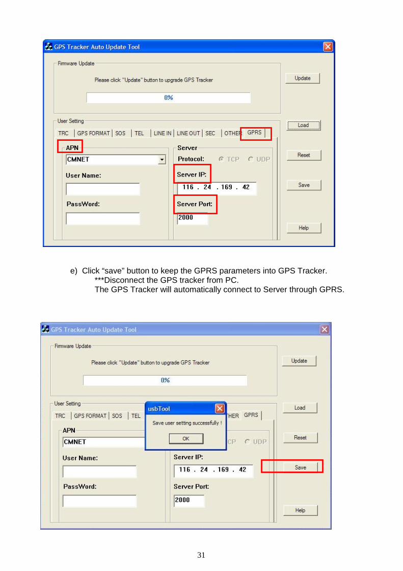
d) Click GPRS button for setting up GPRS parameter.Set your local APN (for example CMNET in china) to APN editor(Please set up user name and password if necessary)Set up server IP with the IP address showed in Server applicationSet Server port to 2000.Set Server protocol to TCP.
31
e) Click “save” button to keep the GPRS parameters into GPS Tracker.***Disconnect the GPS tracker from PC.The GPS Tracker will automatically connect to Server through GPRS.
32
Setup the GPS Tracker by SMS:
GPS Tracker also enables the user to complete the setup through SMS.a) Setup APN, send SMS “security code-I-APN-XXXXXXX ”,XXXXXXX is your local APN name.b) Setup APN username and password if necessary.
Send SMS “security code-I-UN-XXXXXXX ”,XXXXXXX means your user name for APN.Send SMS “security code-I-PW-XXXXXXX ”,XXXXXXX means your password for APN.
c) Setup Server IP.Send SMS “security code-I-IP-XXX.XXX.XXX.XXX ”,XXX.XXX.XXX.XXX means your IP address .
d) Setup Port number.Send SMS “security code-I-PORT-XXXXX ”,XXXXX is the port number of Server application.
e) Start up GPRS connection.Send SMS “security code-GPRS-ON ”, GPS Tracker will try toestablish the GPRS connection according to the user setting.
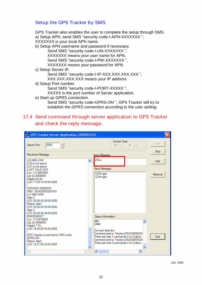
17.4 Send command through server application to GPS Tracker
and check the reply message.
July 2009