getting started - cisco · chapter 1-1 cisco ons 15454 and cisco ons 15327 tl1 command guide, r4.6...
TRANSCRIPT
Cisco ONS 15454 and CisOctober 2008
C H A P T E R1
Getting StartedNote The terms "Unidirectional Path Switched Ring" and "UPSR" may appear in Cisco literature. These terms do not refer to using Cisco ONS 15xxx products in a unidirectional path switched ring configuration. Rather, these terms, as well as "Path Protected Mesh Network" and "PPMN," refer generally to Cisco's path protection feature, which may be used in any topological network configuration. Cisco does not recommend using its path protection feature in any particular topological network configuration.
Transaction Language 1 (TL1) is a subset of the input and output messages contained in the International Telecommunications Union (ITU) Mpath protection an-Machine Language (MML). TL1 provides a standard set of messages that can be used for communicating between operating systems and network elements, and personnel and network elements. The Cisco ONS 15454 and Cisco ONS 15327 can support up to 20 concurrent TL1 sessions in this release. For more information about TL1, refer to Telcordia document GR-833-CORE, Network Maintenance: Network Element and Transport Surveillance Messages.
This chapter provides information and procedures for getting started with TL1:
• Setting up TL1 communication
• TL1 command syntax
• Autonomous messages
• TL1 commands by user security
• Provisioning a DS3E card in CTC using TL1
• Provisioning rules for MXP_2.5G_10G and TXP_MR_10G cards
• Provisioning rules for TXP_MR_2.5G and TXPP_MR_2.5G cards
• CTC interoperability
• Mixed mode timing support
• TL1 command completion behavior
• Test access
• TL1 PCA provisioning
• FTP software download
1-1co ONS 15327 TL1 Command Guide, R4.6
Chapter 1 Getting StartedSetting up TL1 Communication
1.1 Setting up TL1 CommunicationThe period during which a user is logged into the ONS 15454 or ONS 15327 is called a session. There are three options you can use to open a session (login):
• Cisco Transport Controller (CTC)
• Telnet
• Craft interface
The TL1 password (PID) is masked when accessing a TL1 session using any of these options. When you logout of any of these options, you are closing a session. The ONS 15454 and ONS 15327 allow a maximum of 20 (19 telnet sessions and one craft session) concurrent TL1 sessions using any one or any combination of the options listed above. For information on issuing commands to multiple nodes, see Chapter 2, “TL1 Gateway.”
1.1.1 Open a TL1 sessionUse the following procedures to open a TL1 session via the CTC, telnet, or craft interface. In the procedures the Activate and Cancel User commands are shown in their input format. For more information about these and other commands and messages, see Chapter 3, “TL1 Command Descriptions.”
Open a TL1 Session Via CTC
Step 1 From the PC connected to the ONS 15454, start Netscape or Internet Explorer.
Step 2 Enter the ONS 15454 IP address of the node you want to communicate with in the Netscape or Internet Explorer Web address (URL) field.
Step 3 Log into the CTC. The IP address at the title bar should match the IP address of the node you entered in Step 2.
Step 4 Once logged into the CTC, click Tools > Open TL1 Connection.
Step 5 Choose the node you want to communicate with from the Select Node dialog box.
Step 6 Click OK.
A TL1 interface window opens. There are three sub-windows in the TL1 interface window: Request history, Message log, and TL1 request. Type commands in the TL1 request window. You will see responses in the Message log window. The Request history window allows you to recall previous commands by clicking on them.
Step 7 Verify that the Connect button is selected (grayed out).
Step 8 Type the Activate User command in the TL1 request window to open a TL1 session:
ACT-USER:[<TID>]:<UID>:<CTAG>::<PID>; and press Enter.
Note You must press Enter after the semicolon in each TL1 command, or the command will not be issued.
Step 9 Type the Cancel User command in the TL1 request window or press the Disconnect button to close a TL1 session:
1-2Cisco ONS 15454 and Cisco ONS 15327 TL1 Command Guide, R4.6
October 2008
Chapter 1 Getting StartedSetting up TL1 Communication
CANC-USER:[<TID>]:<USERID>:<CTAG>; and press Enter.
Open a TL1 Session Via Telnet
To access TL1 commands in a telnet session over a craft interface or a LAN connection (TCC2 card front panel or backplane pins) you can choose from several ports. Port number 3082 is a raw TCP/IP port; it will not echo and it will not prompt the user. Port number 3083 is a telnet port that uses the telnet protocol and associated telnet escape sequences. Port number 2361 is supported for backward compatibility with earlier releases and has the same behavior as Port 3083 (telnet port). Use the following procedure with PCs running Windows operating systems.
Step 1 At the DOS prompt, type cmd and press Enter. (The same steps can also be done from a Unix prompt).
Step 2 At the DOS command prompt type:
TELNET <NODE IP ADDRESS OR NODE NAME> <PORT NUMBER> and press Enter.
The Node IP address or Node Name refers to the IP address or Node Name of the node you want to communicate with. Port number is the port (2361, 3082, or 3083) where TL1 commands are understood. If the connection is successful, a screen opens with a prompt.
Step 3 Type the Activate User command to open a TL1 session:
ACT-USER:[<TID>]:<UID>:<CTAG>::<PID>;
Note When the semicolon is typed, the command is issued immediately.
Step 4 Type the Cancel User command to close a TL1 session:
CANC-USER:[<TID>]:<USERID>:<CTAG>;
Open a TL1 Session Via Craft Interface
The TCC2 and XTC cards have two built-in interface ports for accessing the ONS 15454 and ONS 15327. With one RJ-45 LAN connection you can access the system using a standard browser interface. In the browser interface, you can perform local and remote Operations, Administration, Maintenance, and Provisioning (OAM&P) functions and open a VT100 emulation window to enter TL1 commands. If a browser is not available, you can access the system using a nine-pin RS-232 port. The RS-232 port supports VT100 emulation such that TL1 commands may be entered directly without a browser. For instructions on how to install the TL1 craft interface, refer to the Cisco ONS 15454 Procedure Guide or the Cisco ONS 15327 Procedure Guide.
Step 1 Connect the serial cable to the RS-232 port on the active TCC2 or XTC card.
Step 2 Configure the terminal emulation software (Hyperterminal):
a. Terminal emulation = vt100
b. Bits per second = 9600
c. Parity = None
d. Stop BITS = 1
1-3Cisco ONS 15454 and Cisco ONS 15327 TL1 Command Guide, R4.6
October 2008
Chapter 1 Getting StartedTL1 Command Syntax
e. Flow control = None
Step 3 Press Enter. An angle bracket prompt (>) appears.
Step 4 At the > prompt, type the Activate User command to open a TL1 session:
ACT-USER:[<TID>]:<UID>:<CTAG>::<PID>;
Note When the semicolon is typed, the TL1 command is issued immediately.
Step 5 Type the Cancel User command to close a TL1 session:
CANC-USER:[<TID>]:<USERID>:<CTAG>;
1.2 TL1 Command SyntaxTL1 commands conform to the following syntax:
a:b:c:d:e: ... z;
where:
“a” is the command code
“b” is the target identifier (TID)
“c” is the access identifier (AID) or the user identifier (UID)
“d” is the correlation tag (CTAG)
“e: ... z;” are other positions required for various commands
The TID, AID, and CTAG route and control the TL1 command. Other parameters provide additional information required to complete the action requested by the command. TL1 command codes, parameter names and parameter values can be either uppercase or lowercase exclusively or any combination of the two, unless specifically noted in the command description.
The TID is a unique name given to each system when it is installed. The name identifies the particular NE (in this case, the ONS 15454 or ONS 15327), to which each command is directed. The value of TID can be any TL1 identifier or text string, but it is limited to 20 characters. An identifier contains any number of letters or digits but must start with a letter. A text string is any alphanumeric or punctuation character enclosed in double-quotes. The presence of the TID is required in all input commands, but its value can be null (represented by two successive colons). The TID can be null when the operating system directly communicates with the target NE. The recommended value for the TID, when it is used, is the target’s CLLI code. To establish the TID for an ONS 15454/15327 node, use the Provisioning > General tabs in CTC.
The AID is an access code used to identify and address specific objects within the ONS 15454 and the ONS 15327. These objects include individual pieces of equipment, transport spans, access tributaries, and other objects.
The CTAG is a unique identifier given to each input command by the user. When the ONS 15454/ONS 15327 system responds to a specific command, it includes the command’s CTAG in the reply. Including the CTAG eliminates discrepancies about which response corresponds to which command. Valid CTAG values include strings of up to six characters comprised of identifiers (alphanumeric, beginning with a letter) or decimal numerals (a string of decimal digits with an optional non-trailing “.”).
1-4Cisco ONS 15454 and Cisco ONS 15327 TL1 Command Guide, R4.6
October 2008
Chapter 1 Getting StartedAutonomous Messages
The following specification characters are used throughout this document as vehicles for defining the syntax:
• < > enclose a symbol specifier, for example <CTAG>.
• [ ] enclose an optional symbol, for example [<TID>].
• “ ” enclose a literal character, for example an output format “SLOT-7:PLUGIN,TC,,,,,,,:\“EQUIPMENT PLUG-IN\”,TCC”
• ^ is a space, a literal blank character used only in examples of messages.
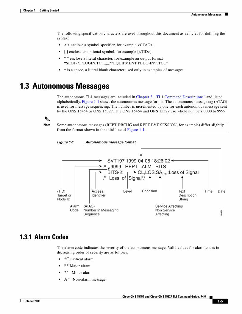
1.3 Autonomous MessagesThe autonomous TL1 messages are included in Chapter 3, “TL1 Command Descriptions” and listed alphabetically. Figure 1-1 shows the autonomous message format. The autonomous message tag (ATAG) is used for message sequencing. The number is incremented by one for each autonomous message sent by the ONS 15454 or ONS 15327. The ONS 15454 and ONS 15327 use whole numbers 0000 to 9999.
Note Some autonomous messages (REPT DBCHG and REPT EVT SESSION, for example) differ slightly from the format shown in the third line of Figure 1-1.
Figure 1-1 Autonomous message format
1.3.1 Alarm CodesThe alarm code indicates the severity of the autonomous message. Valid values for alarm codes in decreasing order of severity are as follows:
• *C Critical alarm
• ** Major alarm
• *^ Minor alarm
• A^ Non-alarm message
SVT197 1999-04-08 18:26:02A 9999 REPT ALM BITS BITS-2: CL,LOS,SA,,,,:Loss of Signal/* Loss of Signal*/
DateTime
Service Affecting/Non Service Affecting
Condition(TID)Target orNode ID
AccessIdentifier
Level
(ATAG)Number In MessagingSequence
Text DescriptionString
AlarmCode
4089
8
1-5Cisco ONS 15454 and Cisco ONS 15327 TL1 Command Guide, R4.6
October 2008
Chapter 1 Getting StartedTL1 Commands by User Security
Critical, Major, and Minor correspond to the reporting of alarmed events. The Non-alarm message designation is used when the NE is reporting non-alarmed events, periodic measurements, or results of previously-scheduled diagnostics or audits. If multiple alarms are reported in the same message, the alarm code is the highest severity of those being reported.
The following is an example of an output message that includes the Critical alarm code:
AB7-56 1970-01-01 16:02:10 *C 100.100 REPT ALM EQPT “SYSTEM:CR,HITEMP,NSA,,,,:\“High Temperature\”,TCC”
For more information about alarms, see Chapter 7, “TL1 Alarms and Errors.”
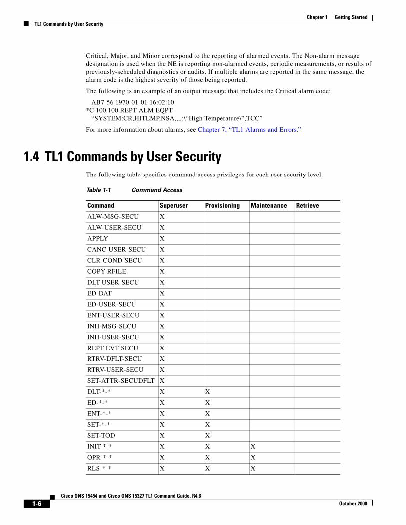
1.4 TL1 Commands by User SecurityThe following table specifies command access privileges for each user security level.
Table 1-1 Command Access
Command Superuser Provisioning Maintenance Retrieve
ALW-MSG-SECU X
ALW-USER-SECU X
APPLY X
CANC-USER-SECU X
CLR-COND-SECU X
COPY-RFILE X
DLT-USER-SECU X
ED-DAT X
ED-USER-SECU X
ENT-USER-SECU X
INH-MSG-SECU X
INH-USER-SECU X
REPT EVT SECU X
RTRV-DFLT-SECU X
RTRV-USER-SECU X
SET-ATTR-SECUDFLT X
DLT-*-* X X
ED-*-* X X
ENT-*-* X X
SET-*-* X X
SET-TOD X X
INIT-*-* X X X
OPR-*-* X X X
RLS-*-* X X X
1-6Cisco ONS 15454 and Cisco ONS 15327 TL1 Command Guide, R4.6
October 2008
Chapter 1 Getting StartedProvisioning Rules for a DS3E Card in CTC Versus TL1
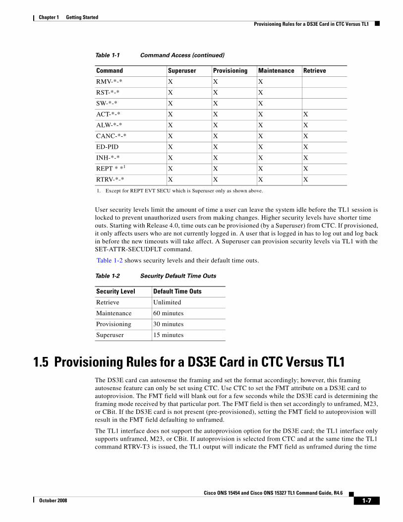
User security levels limit the amount of time a user can leave the system idle before the TL1 session is locked to prevent unauthorized users from making changes. Higher security levels have shorter time outs. Starting with Release 4.0, time outs can be provisioned (by a Superuser) from CTC. If provisioned, it only affects users who are not currently logged in. A user that is logged in has to log out and log back in before the new timeouts will take affect. A Superuser can provision security levels via TL1 with the SET-ATTR-SECUDFLT command.
Table 1-2 shows security levels and their default time outs.
1.5 Provisioning Rules for a DS3E Card in CTC Versus TL1The DS3E card can autosense the framing and set the format accordingly; however, this framing autosense feature can only be set using CTC. Use CTC to set the FMT attribute on a DS3E card to autoprovision. The FMT field will blank out for a few seconds while the DS3E card is determining the framing mode received by that particular port. The FMT field is then set accordingly to unframed, M23, or CBit. If the DS3E card is not present (pre-provisioned), setting the FMT field to autoprovision will result in the FMT field defaulting to unframed.
The TL1 interface does not support the autoprovision option for the DS3E card; the TL1 interface only supports unframed, M23, or CBit. If autoprovision is selected from CTC and at the same time the TL1 command RTRV-T3 is issued, the TL1 output will indicate the FMT field as unframed during the time
RMV-*-* X X X
RST-*-* X X X
SW-*-* X X X
ACT-*-* X X X X
ALW-*-* X X X X
CANC-*-* X X X X
ED-PID X X X X
INH-*-* X X X X
REPT * *1 X X X X
RTRV-*-* X X X X
1. Except for REPT EVT SECU which is Superuser only as shown above.
Table 1-1 Command Access (continued)
Command Superuser Provisioning Maintenance Retrieve
Table 1-2 Security Default Time Outs
Security Level Default Time Outs
Retrieve Unlimited
Maintenance 60 minutes
Provisioning 30 minutes
Superuser 15 minutes
1-7Cisco ONS 15454 and Cisco ONS 15327 TL1 Command Guide, R4.6
October 2008
Chapter 1 Getting StartedProvisioning Rules for MXP_2.5G_10G and TXP_MR_10G Cards
period that the DS3E card (if present) is autosensing the frame format. If the DS3E card is not present (pre-provisioned), the response of the RTRV-T3 command (after CTC sets the FMT to autoprovision) will indicate the FMT field as unframed.
1.6 Provisioning Rules for MXP_2.5G_10G and TXP_MR_10G Cards
The following sections provide rules necessary when performing provisioning with theMXP_2.5G_10G and TXP_MR_10G (MXP/TXP) cards.
1.6.1 Payload Provisioning Rules for MXP/TXP Cards1. You are allowed to change the payload type only if all ports are in OOS state.
2. If the slot is in a regeneration group, changing the payload type affects both cards.
3. Changing the payload is a card-level operation (i.e. all client ports are affected).
4. There should be no DCC enabled on any ports.
5. Only the TXP_MR_10G card can be used for a 10GE payload.
6. To set the 10GE payload for a TXP_MR_10G card, the termination mode must be set to transparent.
7. The payload cannot be changed if any of the ports are a part of any Y cable protection group or are used as the timing source.
8. The TL1 commands to provision are:
ED-DWDM:[<TID>]:<AID>:<CTAG>:::[PEERID=<PEERID>,][NAME=<NAME>,][TERMMODE=<TERMMODE>,][PAYLOAD=<PAYLOAD>,][PWL=<PWL>];RTRV-DWDM:[<TID>]:<AID>:<CTAG>;
1.6.2 Termination Mode Provisioning Rules for MXP/TXP Cards1. Only applicable to payload type of SONET/SDH for MXP_2.5G_10G and TXP_MR_10G cards.
2. Changing termination mode is a card-level operation (i.e. client and trunk must have the same termination mode selection).
3. There should be no DCC enabled on any ports.
4. All ports need to be in OOS state.
5. For transparent termination mode, the trunk port should not be a timing source.
6. Section termination mode is not supported for both the MXP and TXP cards.
7. The trace mode should be set to OFF for the J0 Section trace level on all ports, prior to a change of the termination mode.
8. The TL1 commands to provision are:
• ED-DWDM:[<TID>]:<AID>:<CTAG>:::[PEERID=<PEERID>,][NAME=<NAME>,][TERMMODE=<TERMMODE>,][PAYLOAD=<PAYLOAD>,][PWL=<PWL>];
• RTRV-DWDM:[<TID>]:<AID>:<CTAG>;
1-8Cisco ONS 15454 and Cisco ONS 15327 TL1 Command Guide, R4.6
October 2008
Chapter 1 Getting StartedProvisioning Rules for MXP_2.5G_10G and TXP_MR_10G Cards
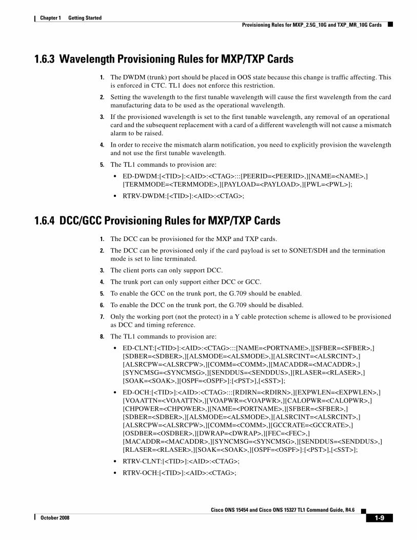
1.6.3 Wavelength Provisioning Rules for MXP/TXP Cards1. The DWDM (trunk) port should be placed in OOS state because this change is traffic affecting. This
is enforced in CTC. TL1 does not enforce this restriction.
2. Setting the wavelength to the first tunable wavelength will cause the first wavelength from the card manufacturing data to be used as the operational wavelength.
3. If the provisioned wavelength is set to the first tunable wavelength, any removal of an operational card and the subsequent replacement with a card of a different wavelength will not cause a mismatch alarm to be raised.
4. In order to receive the mismatch alarm notification, you need to explicitly provision the wavelength and not use the first tunable wavelength.
5. The TL1 commands to provision are:
• ED-DWDM:[<TID>]:<AID>:<CTAG>:::[PEERID=<PEERID>,][NAME=<NAME>,][TERMMODE=<TERMMODE>,][PAYLOAD=<PAYLOAD>,][PWL=<PWL>];
• RTRV-DWDM:[<TID>]:<AID>:<CTAG>;
1.6.4 DCC/GCC Provisioning Rules for MXP/TXP Cards1. The DCC can be provisioned for the MXP and TXP cards.
2. The DCC can be provisioned only if the card payload is set to SONET/SDH and the termination mode is set to line terminated.
3. The client ports can only support DCC.
4. The trunk port can only support either DCC or GCC.
5. To enable the GCC on the trunk port, the G.709 should be enabled.
6. To enable the DCC on the trunk port, the G.709 should be disabled.
7. Only the working port (not the protect) in a Y cable protection scheme is allowed to be provisioned as DCC and timing reference.
8. The TL1 commands to provision are:
• ED-CLNT:[<TID>]:<AID>:<CTAG>:::[NAME=<PORTNAME>,][SFBER=<SFBER>,][SDBER=<SDBER>,][ALSMODE=<ALSMODE>,][ALSRCINT=<ALSRCINT>,][ALSRCPW=<ALSRCPW>,][COMM=<COMM>,][MACADDR=<MACADDR>,][SYNCMSG=<SYNCMSG>,][SENDDUS=<SENDDUS>,][RLASER=<RLASER>,][SOAK=<SOAK>,][OSPF=<OSPF>]:[<PST>],[<SST>];
• ED-OCH:[<TID>]:<AID>:<CTAG>:::[RDIRN=<RDIRN>,][EXPWLEN=<EXPWLEN>,][VOAATTN=<VOAATTN>,][VOAPWR=<VOAPWR>,][CALOPWR=<CALOPWR>,][CHPOWER=<CHPOWER>,][NAME=<PORTNAME>,][SFBER=<SFBER>,][SDBER=<SDBER>,][ALSMODE=<ALSMODE>,][ALSRCINT=<ALSRCINT>,][ALSRCPW=<ALSRCPW>,][COMM=<COMM>,][GCCRATE=<GCCRATE>,][OSDBER=<OSDBER>,][DWRAP=<DWRAP>,][FEC=<FEC>,][MACADDR=<MACADDR>,][SYNCMSG=<SYNCMSG>,][SENDDUS=<SENDDUS>,][RLASER=<RLASER>,][SOAK=<SOAK>,][OSPF=<OSPF>]:[<PST>],[<SST>];
• RTRV-CLNT:[<TID>]:<AID>:<CTAG>;
• RTRV-OCH:[<TID>]:<AID>:<CTAG>;
1-9Cisco ONS 15454 and Cisco ONS 15327 TL1 Command Guide, R4.6
October 2008
Chapter 1 Getting StartedProvisioning Rules for MXP_2.5G_10G and TXP_MR_10G Cards
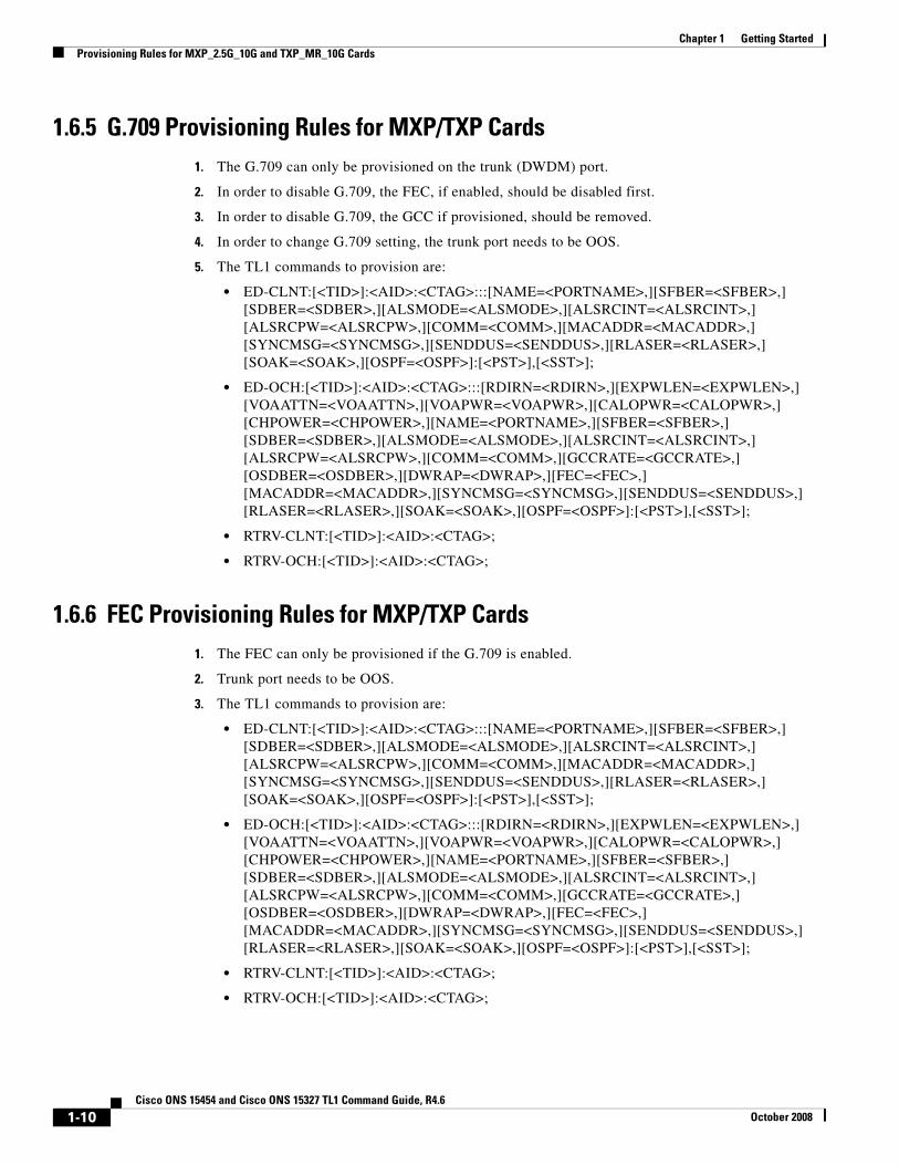
1.6.5 G.709 Provisioning Rules for MXP/TXP Cards1. The G.709 can only be provisioned on the trunk (DWDM) port.
2. In order to disable G.709, the FEC, if enabled, should be disabled first.
3. In order to disable G.709, the GCC if provisioned, should be removed.
4. In order to change G.709 setting, the trunk port needs to be OOS.
5. The TL1 commands to provision are:
• ED-CLNT:[<TID>]:<AID>:<CTAG>:::[NAME=<PORTNAME>,][SFBER=<SFBER>,][SDBER=<SDBER>,][ALSMODE=<ALSMODE>,][ALSRCINT=<ALSRCINT>,][ALSRCPW=<ALSRCPW>,][COMM=<COMM>,][MACADDR=<MACADDR>,][SYNCMSG=<SYNCMSG>,][SENDDUS=<SENDDUS>,][RLASER=<RLASER>,][SOAK=<SOAK>,][OSPF=<OSPF>]:[<PST>],[<SST>];
• ED-OCH:[<TID>]:<AID>:<CTAG>:::[RDIRN=<RDIRN>,][EXPWLEN=<EXPWLEN>,][VOAATTN=<VOAATTN>,][VOAPWR=<VOAPWR>,][CALOPWR=<CALOPWR>,][CHPOWER=<CHPOWER>,][NAME=<PORTNAME>,][SFBER=<SFBER>,][SDBER=<SDBER>,][ALSMODE=<ALSMODE>,][ALSRCINT=<ALSRCINT>,][ALSRCPW=<ALSRCPW>,][COMM=<COMM>,][GCCRATE=<GCCRATE>,][OSDBER=<OSDBER>,][DWRAP=<DWRAP>,][FEC=<FEC>,][MACADDR=<MACADDR>,][SYNCMSG=<SYNCMSG>,][SENDDUS=<SENDDUS>,][RLASER=<RLASER>,][SOAK=<SOAK>,][OSPF=<OSPF>]:[<PST>],[<SST>];
• RTRV-CLNT:[<TID>]:<AID>:<CTAG>;
• RTRV-OCH:[<TID>]:<AID>:<CTAG>;
1.6.6 FEC Provisioning Rules for MXP/TXP Cards1. The FEC can only be provisioned if the G.709 is enabled.
2. Trunk port needs to be OOS.
3. The TL1 commands to provision are:
• ED-CLNT:[<TID>]:<AID>:<CTAG>:::[NAME=<PORTNAME>,][SFBER=<SFBER>,][SDBER=<SDBER>,][ALSMODE=<ALSMODE>,][ALSRCINT=<ALSRCINT>,][ALSRCPW=<ALSRCPW>,][COMM=<COMM>,][MACADDR=<MACADDR>,][SYNCMSG=<SYNCMSG>,][SENDDUS=<SENDDUS>,][RLASER=<RLASER>,][SOAK=<SOAK>,][OSPF=<OSPF>]:[<PST>],[<SST>];
• ED-OCH:[<TID>]:<AID>:<CTAG>:::[RDIRN=<RDIRN>,][EXPWLEN=<EXPWLEN>,][VOAATTN=<VOAATTN>,][VOAPWR=<VOAPWR>,][CALOPWR=<CALOPWR>,][CHPOWER=<CHPOWER>,][NAME=<PORTNAME>,][SFBER=<SFBER>,][SDBER=<SDBER>,][ALSMODE=<ALSMODE>,][ALSRCINT=<ALSRCINT>,][ALSRCPW=<ALSRCPW>,][COMM=<COMM>,][GCCRATE=<GCCRATE>,][OSDBER=<OSDBER>,][DWRAP=<DWRAP>,][FEC=<FEC>,][MACADDR=<MACADDR>,][SYNCMSG=<SYNCMSG>,][SENDDUS=<SENDDUS>,][RLASER=<RLASER>,][SOAK=<SOAK>,][OSPF=<OSPF>]:[<PST>],[<SST>];
• RTRV-CLNT:[<TID>]:<AID>:<CTAG>;
• RTRV-OCH:[<TID>]:<AID>:<CTAG>;
1-10Cisco ONS 15454 and Cisco ONS 15327 TL1 Command Guide, R4.6
October 2008
Chapter 1 Getting StartedProvisioning Rules for MXP_2.5G_10G and TXP_MR_10G Cards
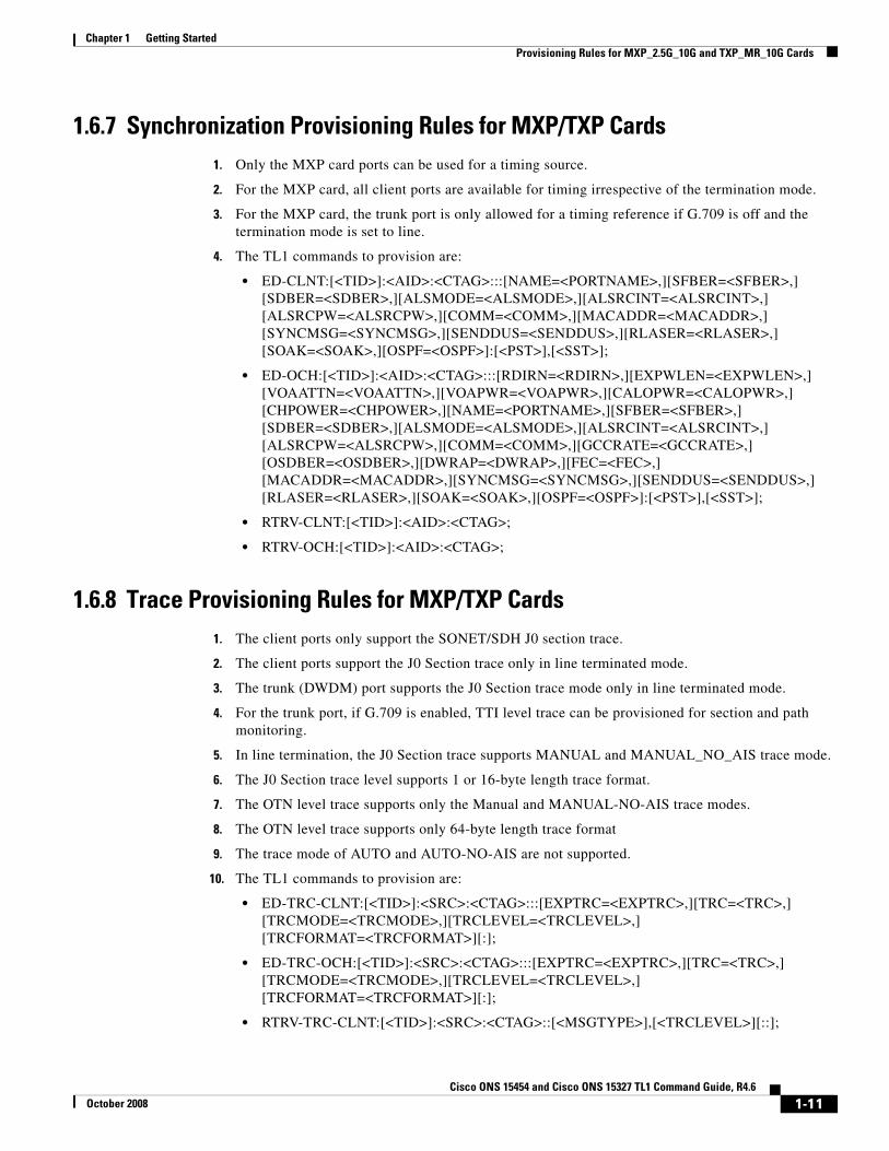
1.6.7 Synchronization Provisioning Rules for MXP/TXP Cards1. Only the MXP card ports can be used for a timing source.
2. For the MXP card, all client ports are available for timing irrespective of the termination mode.
3. For the MXP card, the trunk port is only allowed for a timing reference if G.709 is off and the termination mode is set to line.
4. The TL1 commands to provision are:
• ED-CLNT:[<TID>]:<AID>:<CTAG>:::[NAME=<PORTNAME>,][SFBER=<SFBER>,][SDBER=<SDBER>,][ALSMODE=<ALSMODE>,][ALSRCINT=<ALSRCINT>,][ALSRCPW=<ALSRCPW>,][COMM=<COMM>,][MACADDR=<MACADDR>,][SYNCMSG=<SYNCMSG>,][SENDDUS=<SENDDUS>,][RLASER=<RLASER>,][SOAK=<SOAK>,][OSPF=<OSPF>]:[<PST>],[<SST>];
• ED-OCH:[<TID>]:<AID>:<CTAG>:::[RDIRN=<RDIRN>,][EXPWLEN=<EXPWLEN>,][VOAATTN=<VOAATTN>,][VOAPWR=<VOAPWR>,][CALOPWR=<CALOPWR>,][CHPOWER=<CHPOWER>,][NAME=<PORTNAME>,][SFBER=<SFBER>,][SDBER=<SDBER>,][ALSMODE=<ALSMODE>,][ALSRCINT=<ALSRCINT>,][ALSRCPW=<ALSRCPW>,][COMM=<COMM>,][GCCRATE=<GCCRATE>,][OSDBER=<OSDBER>,][DWRAP=<DWRAP>,][FEC=<FEC>,][MACADDR=<MACADDR>,][SYNCMSG=<SYNCMSG>,][SENDDUS=<SENDDUS>,][RLASER=<RLASER>,][SOAK=<SOAK>,][OSPF=<OSPF>]:[<PST>],[<SST>];
• RTRV-CLNT:[<TID>]:<AID>:<CTAG>;
• RTRV-OCH:[<TID>]:<AID>:<CTAG>;
1.6.8 Trace Provisioning Rules for MXP/TXP Cards1. The client ports only support the SONET/SDH J0 section trace.
2. The client ports support the J0 Section trace only in line terminated mode.
3. The trunk (DWDM) port supports the J0 Section trace mode only in line terminated mode.
4. For the trunk port, if G.709 is enabled, TTI level trace can be provisioned for section and path monitoring.
5. In line termination, the J0 Section trace supports MANUAL and MANUAL_NO_AIS trace mode.
6. The J0 Section trace level supports 1 or 16-byte length trace format.
7. The OTN level trace supports only the Manual and MANUAL-NO-AIS trace modes.
8. The OTN level trace supports only 64-byte length trace format
9. The trace mode of AUTO and AUTO-NO-AIS are not supported.
10. The TL1 commands to provision are:
• ED-TRC-CLNT:[<TID>]:<SRC>:<CTAG>:::[EXPTRC=<EXPTRC>,][TRC=<TRC>,][TRCMODE=<TRCMODE>,][TRCLEVEL=<TRCLEVEL>,][TRCFORMAT=<TRCFORMAT>][:];
• ED-TRC-OCH:[<TID>]:<SRC>:<CTAG>:::[EXPTRC=<EXPTRC>,][TRC=<TRC>,][TRCMODE=<TRCMODE>,][TRCLEVEL=<TRCLEVEL>,][TRCFORMAT=<TRCFORMAT>][:];
• RTRV-TRC-CLNT:[<TID>]:<SRC>:<CTAG>::[<MSGTYPE>],[<TRCLEVEL>][::];
1-11Cisco ONS 15454 and Cisco ONS 15327 TL1 Command Guide, R4.6
October 2008
Chapter 1 Getting StartedProvisioning Rules for MXP_2.5G_10G and TXP_MR_10G Cards
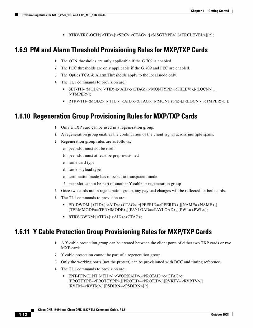
• RTRV-TRC-OCH:[<TID>]:<SRC>:<CTAG>::[<MSGTYPE>],[<TRCLEVEL>][::];
1.6.9 PM and Alarm Threshold Provisioning Rules for MXP/TXP Cards1. The OTN thresholds are only applicable if the G.709 is enabled.
2. The FEC thresholds are only applicable if the G.709 and FEC are enabled.
3. The Optics TCA & Alarm Thresholds apply to the local node only.
4. The TL1 commands to provision are:
• SET-TH-<MOD2>:[<TID>]:<AID>:<CTAG>::<MONTYPE>,<THLEV>,[<LOCN>],,[<TMPER>];
• RTRV-TH-<MOD2>:[<TID>]:<AID>:<CTAG>::[<MONTYPE>],[<LOCN>],<TMPER>[::];
1.6.10 Regeneration Group Provisioning Rules for MXP/TXP Cards1. Only a TXP card can be used in a regeneration group.
2. A regeneration group enables the continuation of the client signal across multiple spans.
3. Regeneration group rules are as follows:
a. peer-slot must not be itself
b. peer-slot must at least be preprovisioned
c. same card type
d. same payload type
e. termination mode has to be set to transparent mode
f. peer slot cannot be part of another Y cable or regeneration group
4. Once two cards are in regeneration group, any payload changes will be reflected on both cards.
5. The TL1 commands to provision are:
• ED-DWDM:[<TID>]:<AID>:<CTAG>:::[PEERID=<PEERID>,][NAME=<NAME>,][TERMMODE=<TERMMODE>,][PAYLOAD=<PAYLOAD>,][PWL=<PWL>];
• RTRV-DWDM:[<TID>]:<AID>:<CTAG>;
1.6.11 Y Cable Protection Group Provisioning Rules for MXP/TXP Cards1. A Y cable protection group can be created between the client ports of either two TXP cards or two
MXP cards.
2. Y cable protection cannot be part of a regeneration group.
3. Only the working ports (not the protect) can be provisioned with DCC and timing reference.
4. The TL1 commands to provision are:
• ENT-FFP-CLNT:[<TID>]:<WORKAID>,<PROTAID>:<CTAG>:::[PROTTYPE=<PROTTYPE>,][PROTID=<PROTID>,][RVRTV=<RVRTV>,][RVTM=<RVTM>,][PSDIRN=<PSDIRN>][:];
1-12Cisco ONS 15454 and Cisco ONS 15327 TL1 Command Guide, R4.6
October 2008
Chapter 1 Getting StartedProvisioning Rules for TXP_MR_2.5G and TXPP_MR_2.5G Cards
• ED-FFP-CLNT:[<TID>]:<AID>:<CTAG>:::[PROTID=<PROTID>,][RVRTV=<RVRTV>,][RVTM=<RVTM>,][PSDIRN=<PSDIRN>][:];
• RTRV-FFP-CLNT:[<TID>]:<AID>:<CTAG>[::::];
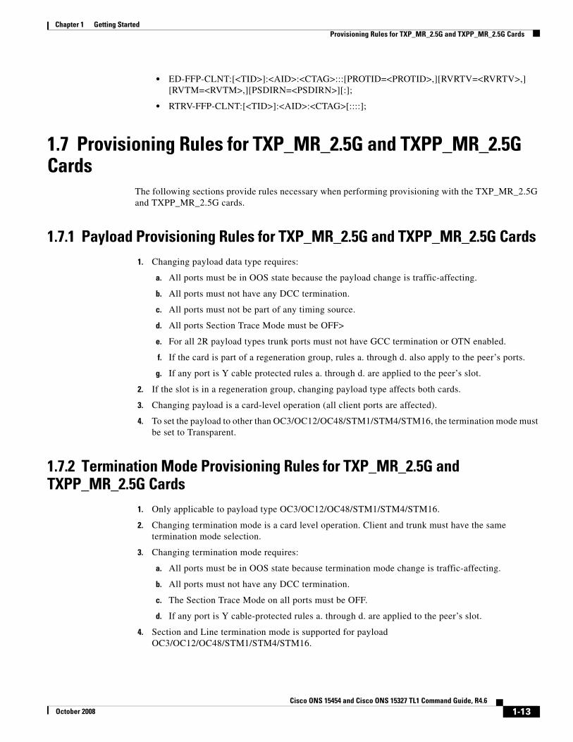
1.7 Provisioning Rules for TXP_MR_2.5G and TXPP_MR_2.5G Cards
The following sections provide rules necessary when performing provisioning with the TXP_MR_2.5G and TXPP_MR_2.5G cards.
1.7.1 Payload Provisioning Rules for TXP_MR_2.5G and TXPP_MR_2.5G Cards1. Changing payload data type requires:
a. All ports must be in OOS state because the payload change is traffic-affecting.
b. All ports must not have any DCC termination.
c. All ports must not be part of any timing source.
d. All ports Section Trace Mode must be OFF>
e. For all 2R payload types trunk ports must not have GCC termination or OTN enabled.
f. If the card is part of a regeneration group, rules a. through d. also apply to the peer’s ports.
g. If any port is Y cable protected rules a. through d. are applied to the peer’s slot.
2. If the slot is in a regeneration group, changing payload type affects both cards.
3. Changing payload is a card-level operation (all client ports are affected).
4. To set the payload to other than OC3/OC12/OC48/STM1/STM4/STM16, the termination mode must be set to Transparent.
1.7.2 Termination Mode Provisioning Rules for TXP_MR_2.5G and TXPP_MR_2.5G Cards
1. Only applicable to payload type OC3/OC12/OC48/STM1/STM4/STM16.
2. Changing termination mode is a card level operation. Client and trunk must have the same termination mode selection.
3. Changing termination mode requires:
a. All ports must be in OOS state because termination mode change is traffic-affecting.
b. All ports must not have any DCC termination.
c. The Section Trace Mode on all ports must be OFF.
d. If any port is Y cable-protected rules a. through d. are applied to the peer’s slot.
4. Section and Line termination mode is supported for payload OC3/OC12/OC48/STM1/STM4/STM16.
1-13Cisco ONS 15454 and Cisco ONS 15327 TL1 Command Guide, R4.6
October 2008
Chapter 1 Getting StartedProvisioning Rules for TXP_MR_2.5G and TXPP_MR_2.5G Cards
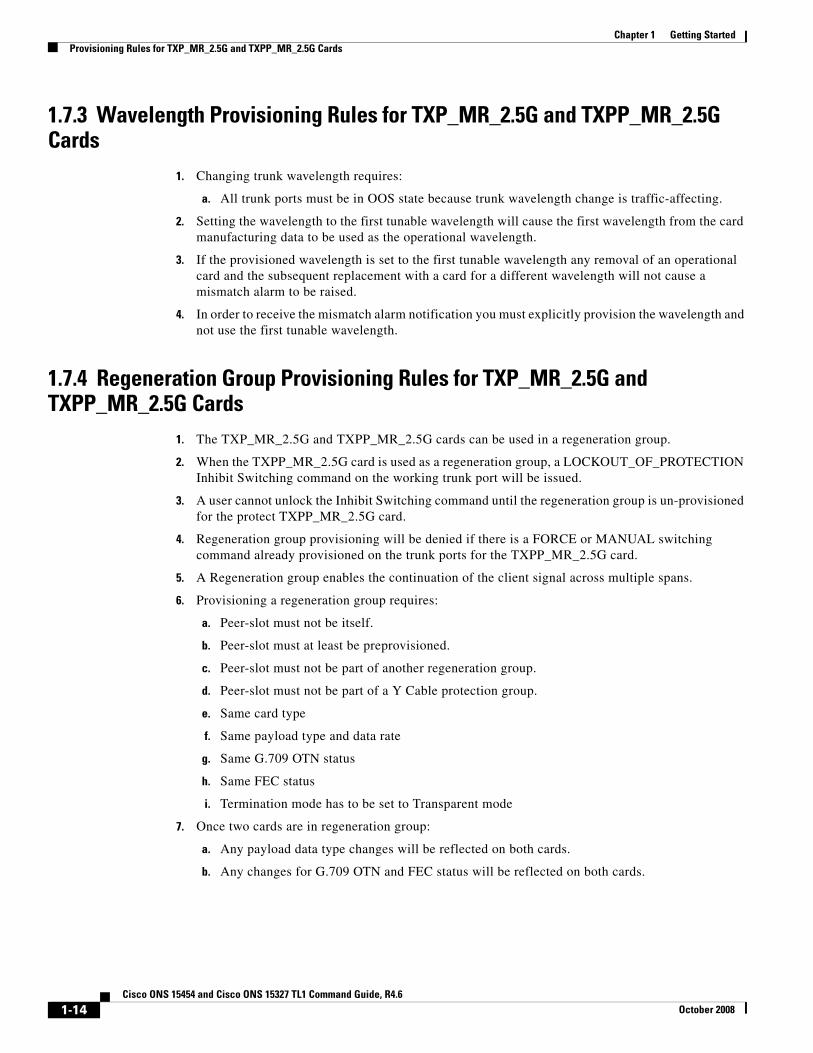
1.7.3 Wavelength Provisioning Rules for TXP_MR_2.5G and TXPP_MR_2.5G Cards
1. Changing trunk wavelength requires:
a. All trunk ports must be in OOS state because trunk wavelength change is traffic-affecting.
2. Setting the wavelength to the first tunable wavelength will cause the first wavelength from the card manufacturing data to be used as the operational wavelength.
3. If the provisioned wavelength is set to the first tunable wavelength any removal of an operational card and the subsequent replacement with a card for a different wavelength will not cause a mismatch alarm to be raised.
4. In order to receive the mismatch alarm notification you must explicitly provision the wavelength and not use the first tunable wavelength.
1.7.4 Regeneration Group Provisioning Rules for TXP_MR_2.5G and TXPP_MR_2.5G Cards
1. The TXP_MR_2.5G and TXPP_MR_2.5G cards can be used in a regeneration group.
2. When the TXPP_MR_2.5G card is used as a regeneration group, a LOCKOUT_OF_PROTECTION Inhibit Switching command on the working trunk port will be issued.
3. A user cannot unlock the Inhibit Switching command until the regeneration group is un-provisioned for the protect TXPP_MR_2.5G card.
4. Regeneration group provisioning will be denied if there is a FORCE or MANUAL switching command already provisioned on the trunk ports for the TXPP_MR_2.5G card.
5. A Regeneration group enables the continuation of the client signal across multiple spans.
6. Provisioning a regeneration group requires:
a. Peer-slot must not be itself.
b. Peer-slot must at least be preprovisioned.
c. Peer-slot must not be part of another regeneration group.
d. Peer-slot must not be part of a Y Cable protection group.
e. Same card type
f. Same payload type and data rate
g. Same G.709 OTN status
h. Same FEC status
i. Termination mode has to be set to Transparent mode
7. Once two cards are in regeneration group:
a. Any payload data type changes will be reflected on both cards.
b. Any changes for G.709 OTN and FEC status will be reflected on both cards.
1-14Cisco ONS 15454 and Cisco ONS 15327 TL1 Command Guide, R4.6
October 2008
Chapter 1 Getting StartedProvisioning Rules for TXP_MR_2.5G and TXPP_MR_2.5G Cards
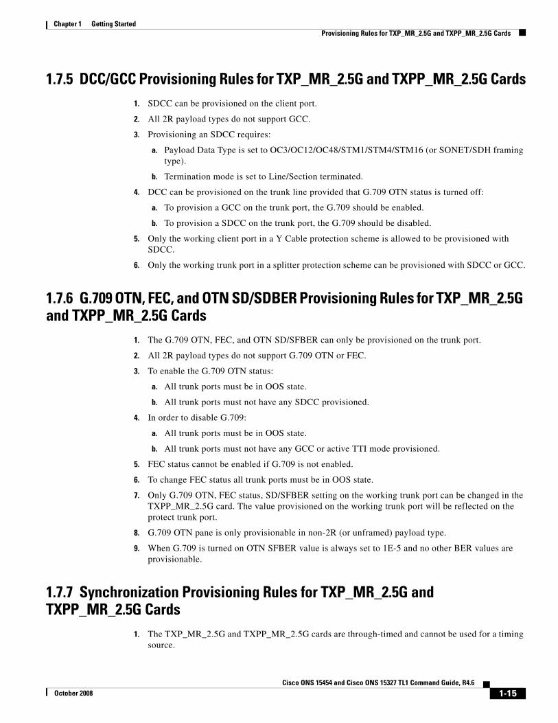
1.7.5 DCC/GCC Provisioning Rules for TXP_MR_2.5G and TXPP_MR_2.5G Cards1. SDCC can be provisioned on the client port.
2. All 2R payload types do not support GCC.
3. Provisioning an SDCC requires:
a. Payload Data Type is set to OC3/OC12/OC48/STM1/STM4/STM16 (or SONET/SDH framing type).
b. Termination mode is set to Line/Section terminated.
4. DCC can be provisioned on the trunk line provided that G.709 OTN status is turned off:
a. To provision a GCC on the trunk port, the G.709 should be enabled.
b. To provision a SDCC on the trunk port, the G.709 should be disabled.
5. Only the working client port in a Y Cable protection scheme is allowed to be provisioned with SDCC.
6. Only the working trunk port in a splitter protection scheme can be provisioned with SDCC or GCC.
1.7.6 G.709 OTN, FEC, and OTN SD/SDBER Provisioning Rules for TXP_MR_2.5G and TXPP_MR_2.5G Cards
1. The G.709 OTN, FEC, and OTN SD/SFBER can only be provisioned on the trunk port.
2. All 2R payload types do not support G.709 OTN or FEC.
3. To enable the G.709 OTN status:
a. All trunk ports must be in OOS state.
b. All trunk ports must not have any SDCC provisioned.
4. In order to disable G.709:
a. All trunk ports must be in OOS state.
b. All trunk ports must not have any GCC or active TTI mode provisioned.
5. FEC status cannot be enabled if G.709 is not enabled.
6. To change FEC status all trunk ports must be in OOS state.
7. Only G.709 OTN, FEC status, SD/SFBER setting on the working trunk port can be changed in the TXPP_MR_2.5G card. The value provisioned on the working trunk port will be reflected on the protect trunk port.
8. G.709 OTN pane is only provisionable in non-2R (or unframed) payload type.
9. When G.709 is turned on OTN SFBER value is always set to 1E-5 and no other BER values are provisionable.
1.7.7 Synchronization Provisioning Rules for TXP_MR_2.5G and TXPP_MR_2.5G Cards
1. The TXP_MR_2.5G and TXPP_MR_2.5G cards are through-timed and cannot be used for a timing source.
1-15Cisco ONS 15454 and Cisco ONS 15327 TL1 Command Guide, R4.6
October 2008
Chapter 1 Getting StartedProvisioning Rules for TXP_MR_2.5G and TXPP_MR_2.5G Cards
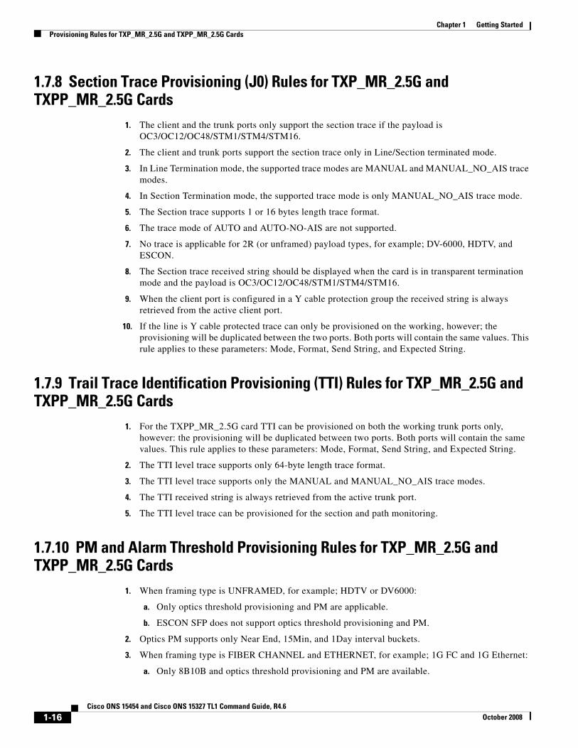
1.7.8 Section Trace Provisioning (J0) Rules for TXP_MR_2.5G and TXPP_MR_2.5G Cards
1. The client and the trunk ports only support the section trace if the payload is OC3/OC12/OC48/STM1/STM4/STM16.
2. The client and trunk ports support the section trace only in Line/Section terminated mode.
3. In Line Termination mode, the supported trace modes are MANUAL and MANUAL_NO_AIS trace modes.
4. In Section Termination mode, the supported trace mode is only MANUAL_NO_AIS trace mode.
5. The Section trace supports 1 or 16 bytes length trace format.
6. The trace mode of AUTO and AUTO-NO-AIS are not supported.
7. No trace is applicable for 2R (or unframed) payload types, for example; DV-6000, HDTV, and ESCON.
8. The Section trace received string should be displayed when the card is in transparent termination mode and the payload is OC3/OC12/OC48/STM1/STM4/STM16.
9. When the client port is configured in a Y cable protection group the received string is always retrieved from the active client port.
10. If the line is Y cable protected trace can only be provisioned on the working, however; the provisioning will be duplicated between the two ports. Both ports will contain the same values. This rule applies to these parameters: Mode, Format, Send String, and Expected String.
1.7.9 Trail Trace Identification Provisioning (TTI) Rules for TXP_MR_2.5G and TXPP_MR_2.5G Cards
1. For the TXPP_MR_2.5G card TTI can be provisioned on both the working trunk ports only, however: the provisioning will be duplicated between two ports. Both ports will contain the same values. This rule applies to these parameters: Mode, Format, Send String, and Expected String.
2. The TTI level trace supports only 64-byte length trace format.
3. The TTI level trace supports only the MANUAL and MANUAL_NO_AIS trace modes.
4. The TTI received string is always retrieved from the active trunk port.
5. The TTI level trace can be provisioned for the section and path monitoring.
1.7.10 PM and Alarm Threshold Provisioning Rules for TXP_MR_2.5G and TXPP_MR_2.5G Cards
1. When framing type is UNFRAMED, for example; HDTV or DV6000:
a. Only optics threshold provisioning and PM are applicable.
b. ESCON SFP does not support optics threshold provisioning and PM.
2. Optics PM supports only Near End, 15Min, and 1Day interval buckets.
3. When framing type is FIBER CHANNEL and ETHERNET, for example; 1G FC and 1G Ethernet:
a. Only 8B10B and optics threshold provisioning and PM are available.
1-16Cisco ONS 15454 and Cisco ONS 15327 TL1 Command Guide, R4.6
October 2008
Chapter 1 Getting StartedProvisioning Rules for TXP_MR_2.5G and TXPP_MR_2.5G Cards
b. 2G Fiber Channel does not support 8B10B threshold provisioning and PM.
4. 8B10B applies to both Tx and Rx directions.
5. 8B10B PM supports only Near End, 15Min and 1Day interval buckets.
6. When framing type is SONET/SDH all monitored PM parameter terminology will follow the current chassis type.
7. The OTN thresholds are only applicable if G.709 OTN status is enabled.
8. The FEC thresholds are only applicable if the G.709 and FEC are enabled.
9. If the line is configured in a Y cable or Splitter protection group, only the working line thresholds can be provisioned. The working line thresholds will be reflected on the protect line thresholds. This rule applies for all threshold types including G.709 OTN and FEC thresholds.
10. Payload PM can be independently retrieved for both the working and protect port.
1.7.11 Y Cable Protection Group Provisioning Rules for TXP_MR_2.5G and TXPP_MR_2.5G Cards
1. A Y cable protection group can be created between the client ports of two TXP_MR_2.5G cards only.
2. While in Y cable protection, a TXP_MR_2.5G/TXPP_MR_2.5G card cannot be part of a regeneration group.
3. Only the working client port can be provisioned with SDCC.
4. Y cable cannot be provisioned for the TXPP_MR_2.5G card.
1.7.12 Loopback Provisioning Rules for TXP_MR_2.5G and TXPP_MR_2.5G Cards
1. Loopback can be provisioned on the client and trunk ports.
2. Both Terminal and Facility loopback types can be provisioned.
3. Loopback is not applicable when framing type is UNFRAMED.
4. For the TXPP_MR_2.5G card, the following loopback rules apply to the trunk ports:
a. Only one loopback is allowed to be provisioned at the trunk ports at any given time.
b. Loopback is allowed if the sibling trunk port is not IS.
c. Provisioning a loopback on a trunk port will trigger the Inhibit Switching command LOCKOUT_OF_PROTECTION or LOCKOUT_OF_WORKING depending on whether the working or the protect is placed in a loopback.
d. Once a loopback is provisioned on a trunk port both the trunk ports will transmit the signal of the loopback port.
e. Loopback will be denied if there is a FORCE or MANUAL switching command in place on the trunk ports.
f. You cannot remove the Inhibit Switching command issued as a result of the loopback. This Inhibit Switching command will be removed only when the loopback is removed.
1-17Cisco ONS 15454 and Cisco ONS 15327 TL1 Command Guide, R4.6
October 2008
Chapter 1 Getting StartedProvisioning Rules for TXP_MR_2.5G and TXPP_MR_2.5G Cards
1.7.13 ALS Provisioning Rules for TXP_MR_2.5G and TXPP_MR_2.5G Cards1. ALS can be provisioned on the client and trunk ports.
2. If the trunk port is configured in a Splitter protection group, only the working trunk port can be provisioned for ALS, however; ALS provisioning on the working trunk port will be reflected on the protect port.
3. For the protected TXPP_MR_2.5G card, ALS mode will only take effect when both ports receive LOS.
1.7.14 Port State Model Provisioning Rules for TXP_MR_2.5G and TXPP_MR_2.5G Cards
1. The Enhanced state model port state of primary state=OOS and secondary state=AINS is not supported for the 1GigE/2GigE payload type.
2. The working and protect port can be put in IS/OOS independently.
3. For the TXPP_MR_2.5G card:
a. Setting the protect trunk port to OOS will enable the suppression of alarms on that port and will enable the card to be used like an unprotected card but the card still cannot be used for a Y cable protection group.
b. Setting the protect trunk port to OOS will not switch off the transmit laser unless both trunk ports are OOS.
c. The protect trunk port cannot be IS if there is a loopback or a regeneration group provisioned.
1.7.15 SONET-Related Provisioning Rules for TXP_MR_2.5G and TXPP_MR_2.5G Cards
1. The SD/SFBER can only be provisioned on the working trunk port for the TXPP_MR_2.5G card. Values set at the working port will be reflected on the trunk port.
1.7.16 Overhead Circuit Rules for TXP_MR_2.5G and TXPP_MR_2.5G Cards
Note Applicable for provisioning from CTC only.
1. LOW/EOW is possible between the AIC-I, OCn and TXP/MXP cards in any combination in line-terminated mode.
2. F1/D4-D12 UDC:
a. Not possible between TXP/TXPP and AIC-I cards in line-terminated mode.
b. Not possible between TXP/TXPP and OCn cards in line-terminated mode.
c. Possible between OCn ports.
3. All OH bytes are passed across client and DWDM ports in transparent mode.
4. SDCC/LDCC tunneling is not possible in line-terminated mode.
1-18Cisco ONS 15454 and Cisco ONS 15327 TL1 Command Guide, R4.6
October 2008
Chapter 1 Getting StartedCTC Interoperability
5. No end-to-end OH circuit provisioning. In R4.6 you can stitch them at each node.
1.7.17 Hardware Limitation Rules for TXP_MR_2.5G and TXPP_MR_2.5G Cards1. ESCON SFP does not support any monitoring.
2. Optics thresholds and PM are not shown on client ports.
3. HI/LO-TXPOWER is not supported for TXP_MR_2.5G and TXPP_MR_2.5G Cards.
1.8 CTC InteroperabilityA TL1 cross-connect that has been upgraded to a CTC circuit can no longer be managed by TL1. For example, if you issue a DLT-CRS-<STS_PATH> command to delete a circuit, you will see that the circuit still appears in CTC as “incomplete.” The reason for this is because in addition to creating cross-connects (as TL1 does), CTC creates another object on the source node that stores network-level circuit attributes. CTC will continue to see that object after the cross-connect is deleted which is why it shows an incomplete circuit.
Starting with R3.4, there is a Create cross connects only (TL1-like) check box that appears in CTC when creating circuits. If applicable, you can check this box to create one or more cross-connects to complete a signal path for TL1-generated circuits. If this box is checked, you cannot assign a name to the circuit; and VT tunnels, Ethergroup sources, and drops are unavailable. Refer to the Cisco ONS 15454 Procedure Guide or the Cisco ONS 15327 Procedure Guide for information about CTC circuit creation.
1.9 Mixed Mode Timing SupportAlthough TL1 supports mixed mode timing, Cisco strongly advises against its implementation. Mixed mode timing is not a recommended timing mode because of the inherent risk of creating timing loops. Refer to Telcordia document GR-436-CORE, Digital Network Synchronization Plan for recommended synchronization planning. Refer to the Cisco ONS 15454 Procedure Guide or the Cisco ONS 15327 User Documentation for information about setting up ONS 15454/15327 timing. For further assistance contact the Cisco Technical Assistance Center (TAC) at www.cisco.com or call (800) 553-2447 for unresolved problems.
1.10 TL1 Command Completion BehaviorWhen you enter a TL1 command, one of three completion codes will be returned. The completion codes are: completed (COMPLD), partial (PRTL), and deny (DENY). You can specify an explicit, implicit, or explicit with implicit list as explained in the following sections.
1.10.1 General Rules
Note The command completion behavior does not apply to RTRV-CRS, RTRV-ALM, and RTVR-COND commands.
1-19Cisco ONS 15454 and Cisco ONS 15327 TL1 Command Guide, R4.6
October 2008
Chapter 1 Getting StartedTL1 Command Completion Behavior
1.10.1.1 Explicit List of AIDs - No Wildcards
If a set of AIDs is explicitly listed, including a set of just one AID, then each AID must complete successfully to return a COMPLD message. If more than one AID is in the set and at least one AID succeeds but all do not, then a PRTL with errors for each failed AID is returned. If all AIDs in the set fail, a DENY with errors for each failed AID is returned.
SLOT-1 FAC-2-1&FAC-3-3&FAC-4-2
1.10.1.2 Implicit List of AIDs - Single AID With Wildcard
If a set of AIDs is implied by the use of the ALL modifier on a single AID, then follow the same rules as in the “Explicit List of AIDs - No Wildcards” section on page 1-20. The caveat is that the implicit list only includes AIDs that apply to the command:
SLOT-ALL FAC-1-ALLSTS-3-ALL
where Slot 3 contains an OC-12 and the command is ED-STS1 but STS-3-4 and STS-3-7 are STS3C. The set implied by STS-3-ALL then only contains STS-3-{1,2,3,10,11,12} and will not return an error for STS-3-{4,5,6,7,8,9}. Disregard the STS3C in this case because the modifier of the command specifies that the user is only interested in STS-1 paths. The rule specified in this section then applies to the implicit set of {1,2,3,10,11,12}.
1.10.1.3 Explicit List Grouped With Implicit List
If the set of AIDs is comprised of two subsets, one set including explicitly stated AIDs and the other set implied by one or more AID(s) with the ALL modifier, then follow the rules of the“Explicit List of AIDs - No Wildcards” section on page 1-20 and the “Implicit List of AIDs - Single AID With Wildcard” section on page 1-20, respectively.
FAC-1-1&FAC-2-ALL FAC-3-ALL&FAC-7-ALL STS-2-ALL&STS-12-1&STS-13-2&STS-14-ALL
1.10.2 Command Completion Behavior for Retrieval of Cross-ConnectionsWhen you enter a RTRV-CRS command, one of three completion codes will be returned. The completion codes are: completed (COMPLD), partial (PRTL), and deny (DENY). You can specify an explicit, implicit, or explicit with implicit list as explained in the following sections.
1.10.2.1 Explicit List of AIDs - No Wildcards
For an explicit list of AIDs on a RTRV-CRS command, an error code will be returned for each AID that fails validation (e.g. the user specifies STS-N-13 when SLOT-N only contains an OC-12) or for each AID where no matching cross-connection is found. To determine the completion code, follow the rules from the “Explicit List of AIDs - No Wildcards” section on page 1-20. If the result is either PRTL or COMPLD, then a list of matching cross-connections will accompany the response.
1-20Cisco ONS 15454 and Cisco ONS 15327 TL1 Command Guide, R4.6
October 2008
Chapter 1 Getting StartedTest Access
1.10.2.2 Implicit List of AIDs - Single AID With Wildcard
If a set of AIDs is implied by the use of the ALL modifier on a single AID, then follow the same AID expansion rule as defined in the example from the “Implicit List of AIDs - Single AID With Wildcard” section on page 1-20. Then apply the following rules to the set:
1. If all valid AIDs match, COMPLD is returned with a matching list of cross-connections.
2. If some valid AIDs match but not all, COMPLD is returned with a matching list of cross-connections.
3. If all valid AIDs fail to match, DENY is returned.
RTRV-CRS-STS1:[<TID>]:STS-9-ALL:<CTAG>; where STS-9-ALL maps to STS-9-{1,2,3,10,11,12} because there is a single-port OC-12 card in Slot 3 with STS-3C defined for STS-9-4 and STS-9-7. You then traverse the set and return only the STS1 cross-connections that exist using end points in that set. If no cross-connections are retrieved, COMPLD is returned.
1.10.2.3 Explicit List Grouped With Implicit List
When you have determined the implicit list, apply the rules from the “Implicit List of AIDs - Single AID With Wildcard” section on page 1-21 to the implicit list and the rules from the “Explicit List of AIDs - No Wildcards” section on page 1-20 to the explicit list. Apply the following logic to the results from the two subsets:
1. Explicit list returns COMPLD, implicit list returns COMPLD, return COMPLD plus matching list
2. Explicit list returns COMPLD, implicit list returns DENY, return PRTLwith errors plus matching list
3. Explicit list returns PRTL, implicit list returns COMPLD, return PRTL with errors plus matching lists
4. Explicit list returns PRTL, implicit list returns DENY, return PRTL with errors plus matching list
5. Explicit list returns DENY, implicit list returns COMPLD, return PRTL with errors plus matching list
6. Explicit list returns DENY, implicit list returns DENY, return DENY with errors
1.11 Test AccessThe test access (TACC) feature allows a third-party Broadband Remote Test Unit (BRTU) to create non-intrusive test access points (TAPs) to monitor the circuits on the ONS 15454/15327 for errors. The test access feature also allows the circuit to be split (intrusive), so that the transmission paths can be tested for bit errors via the use of various bit test patterns. The two BRTUs supported by the ONS 15454/15327 are the Hekimian/Spirent BRTU-93 (6750) and the TTC/Acterna Centest 650.
The test access functionality provides TL1 commands for creating and deleting TAPs, connecting or disconnecting TAPs to circuit cross-connects and changing the mode of test access on the ONS 15454/15327. You can view test access information in CTC; in node view click the Maintenance > Test Access tabs.
Refer to Telcordia document GR-834-CORE, Network Maintenance: Access and Testing and GR-1402-CORE, Network Maintenance: Access Testing - DS3 HCDS TSC/RTU and DTAU Functional Requirements for more information about Test Access. See Chapter 3, “TL1 Command Descriptions” for TL1 command information.
1-21Cisco ONS 15454 and Cisco ONS 15327 TL1 Command Guide, R4.6
October 2008
Chapter 1 Getting StartedTest Access
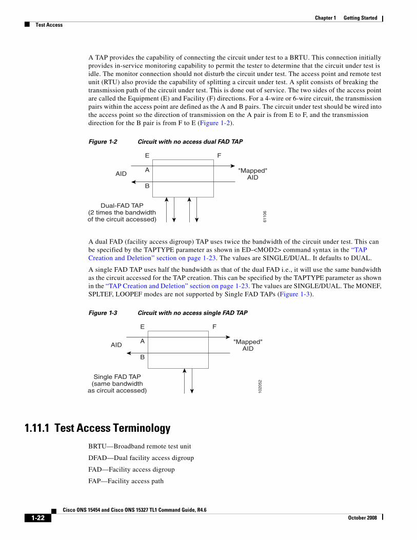
A TAP provides the capability of connecting the circuit under test to a BRTU. This connection initially provides in-service monitoring capability to permit the tester to determine that the circuit under test is idle. The monitor connection should not disturb the circuit under test. The access point and remote test unit (RTU) also provide the capability of splitting a circuit under test. A split consists of breaking the transmission path of the circuit under test. This is done out of service. The two sides of the access point are called the Equipment (E) and Facility (F) directions. For a 4-wire or 6-wire circuit, the transmission pairs within the access point are defined as the A and B pairs. The circuit under test should be wired into the access point so the direction of transmission on the A pair is from E to F, and the transmission direction for the B pair is from F to E (Figure 1-2).
Figure 1-2 Circuit with no access dual FAD TAP
A dual FAD (facility access digroup) TAP uses twice the bandwidth of the circuit under test. This can be specified by the TAPTYPE parameter as shown in ED-<MOD2> command syntax in the “TAP Creation and Deletion” section on page 1-23. The values are SINGLE/DUAL. It defaults to DUAL.
A single FAD TAP uses half the bandwidth as that of the dual FAD i.e., it will use the same bandwidth as the circuit accessed for the TAP creation. This can be specified by the TAPTYPE parameter as shown in the “TAP Creation and Deletion” section on page 1-23. The values are SINGLE/DUAL. The MONEF, SPLTEF, LOOPEF modes are not supported by Single FAD TAPs (Figure 1-3).
Figure 1-3 Circuit with no access single FAD TAP
1.11.1 Test Access TerminologyBRTU—Broadband remote test unit
DFAD—Dual facility access digroup
FAD—Facility access digroup
FAP—Facility access path
6110
6
A
E
B
F
"Mapped"AID
AID
Dual-FAD TAP(2 times the bandwidthof the circuit accessed)
1020
52
A
E
B
F
"Mapped"AID
AID
Single FAD TAP(same bandwidth
as circuit accessed)
1-22Cisco ONS 15454 and Cisco ONS 15327 TL1 Command Guide, R4.6
October 2008
Chapter 1 Getting StartedTest Access
LOOPE—Split/loop access on A and B paths equipment side
LOOPF—Split/loop access on A and B paths facility side
MONE—Monitor access with signal detector on A path
MONF—Monitor access with signal detector on B path
MONEF—Monitor access with signal detector on A and B paths
QRS—Quasi-random signal (bit test pattern)
SPLTA—Split access on A path with signal detector from equipment, QRS on facility side
SPLTB—Split access on B path with signal detector from equipment, QRS on equipment side
SPLTE—Split access on A and B paths with signal detector from equipment, QRS on equipment side
SPLTF—Split access on A and B paths with signal detector from equipment, QRS on facility side
SPLTEF—Split access on A and B paths for testing in both equipment and facility directions
TACC—Test access
TAP—Test access path/point
Path Naming Conventions:
E—Equipment test access point direction
F—Facility test access point direction
A—Transmission path (the direction of transmission on the A pair is from E to F)
B—Transmission path (the transmission direction for the B pair is from F to E)
1.11.2 TAP Creation and DeletionThe edit command (ED-<rr>) is used to change an existing port, STS, or VT to a TAP.
Input Format:
ED- (T1, T3, STS1, STS3c, STS6c, STS9c, STS12c, STS24c, STS48c, VT1, DS1):[<TID>]:<AID>:<CTAG>[:::TACC=<TACC>][TAPTYPE=<TAPTYPE>];
Edit an existing port, STS, or VT and change it to a TAP so it can be used when requesting TACC connections. Includes a new optical parameter TACC=n that defines the port, STS, or VT as a TAP with a selected unique TAP number. This TAP number will be used when requesting test access connections to circuit cross-connections under test. The TAP creation will fail if there is a cross-connection already on the port, STS, or VT.
Notes:
1. This command generates a REPT DBCHG message.
2. The alarms and conditions on test access paths can be retrieved by the RTRV-ALM-ALL or RTRV-ALM-<MOD2> commands
3. The TAP is a persistent object. It will exist after the user has logged out of the TL1 session.
The following list applies to TAP numbers:
1. The TAP number is an integer within the range of 1–999. When TACC=0 is specified, the TAP is deleted (if already present).
2. The TAP number is unique across T1/T3/STS/VT/DS1 TAPs in the system.
3. The TAP number is not editable.
1-23Cisco ONS 15454 and Cisco ONS 15327 TL1 Command Guide, R4.6
October 2008
Chapter 1 Getting StartedTest Access
1.11.2.1 ED-T1
When the ED-T1 command is issued with a specified TACC value for a given T1 port/facility, a dual facility access group (DFAD) is created by using the specified port/facility and the consecutive port/facility.
The command in example Example 1-1 creates a DFAD on FAC-1-1 and FAC-1-2.
Example 1-1 ED-T1::FAC-1-1:12:::TACC=1;
DV9-99 1970-01-02 03:16:11
M 12 COMPLD
;
Note These ports/facilities cannot be used for the creation of cross-connects until the TAP is deleted.
1.11.2.2 ED-T3
When the ED-T3 command is issued with a specified TACC value for a given T3 port/facility, a DFAD is created by using the specified port/facility and the consecutive port/facility.
The command in Example 1-2 creates a T3 DFAD on FAC-2-1 and FAC-2-2.
Example 1-2 ED-T3::FAC-2-1:12:::TACC=2;
DV9-99 1970-01-02 03:16:11
M 12 COMPLD
;
Note These ports/facilities cannot be used for the creation of cross-connects until the TAP is deleted.
1.11.2.3 ED-DS1
When the ED-DS1 command is issued with a specified TACC value for a given DS1 facility on a DS3XM, a DFAD is created by using the specified facility and the consecutive port/facility.
The command in Example 1-3 creates DFAD on DS1-2-1-1 and DS1-2-1-2.
Example 1-3 ED-DS1::DS1-2-1-1:12:::TACC=3;
DV9-99 1970-01-02 03:16:11
M 12 COMPLD
;
Note These ports/facilities cannot be used for the creation of cross-connects until the TAP is deleted.
1-24Cisco ONS 15454 and Cisco ONS 15327 TL1 Command Guide, R4.6
October 2008
Chapter 1 Getting StartedTest Access
1.11.2.4 ED-STSn
When the ED-STSn command is issued for a TACC it assigns the STS for the first two-way test access connection and STS+1 as the second 2-way connection. For STS3c, STS9c, STS12c, STS24c, and STS48c the next consecutive STS of same width is chosen. The TAP creation will fail if either of the consecutive STSs are not available.
The command in Example 1-4 creates a TAP on STS-5-1 and STS-5-2.
Example 1-4 ED-STS1::STS-5-1:12:::TACCC=4
DV9-99 1970-01-02 03:16:11
M 12 COMPLD
;
Note These STSs cannot be used for the creation of cross-connects until the TAP is deleted.
The command in Example 1-5 creates an STS24C dual TAP on STS-6-1 and STS-6-25.
Example 1-5 ED-STS24C::STS-6-1:12:::TACC=5:
DV9-99 1970-01-02 03:16:11
M 12 COMPLD
;
Note These STSs cannot be used for the creation of cross-connects until the TAP is deleted.
1.11.2.5 ED-VT1
When the ED-VT1 command is issued for a TACC, a VT TAP is created. The specified VT AID is taken as the first VT connection, the second VT connection is made by incrementing the VT group and keeping the VT number the same.
The command in Example 1-6 creates a VT TAP on VT1-1-1-1-1 and VT1-1-1-2-1.
Example 1-6 ED-VT1-1-1-1-1:12:::TACC=6;
DV9-99 1970-01-02 03:16:11
M 12 COMPLD
;
Note These VTs cannot be used for the creation of cross-connects until the TAP is deleted.
1.11.3 Connect Test Access PointsThe CONN-TACC command (CONN-TACC-<rr>) is used to make a connection between the TAP and the circuit or cross-connect under test.
1-25Cisco ONS 15454 and Cisco ONS 15327 TL1 Command Guide, R4.6
October 2008
Chapter 1 Getting StartedTest Access
Input Format: CONN-TACC-(T1, T3, STS1, STS3C, STS6C, STS9C, STS12C, STS24C, STS48C, VT1, DS1):[<TID>]:<AID>:<CTAG>::<TAP>:MD=<MD>;
Connect the port/STS/VT defined by <AID> to the port/STS/VT defined by the <TAP> number. The mode of test access to the circuit/cross-connect is specified by <MD>. The modes can be either of monitor (non-intrusive), split or loop (intrusive) modes. The various modes are described in the “Test Access Mode Definitions” section on page 1-31.
Note The connection is maintained only for the duration of the TL1 session (non-persistent).
Note The TAP number is displayed at the output if the CONN-TACC command completes successfully.
Error Codes Supported:
RTBY—Requested TAP busy
RTEN—Requested TAP does not exist
SCAT—Circuit is already connected to another TAP
SRCN—Requested condition already exists
IIAC—Invalid access identifier (AID)
EANS—Access not supported
SRAC—Requested access configuration is invalid
The command in Example 1-7 creates a connection between TAP with number one and the port/facility FAC-1-3 with access mode as MONE. The various modes are described in the “Test Access Mode Definitions” section on page 1-31.
Example 1-7 CONN-TACC-T1::FAC-1-3:12::1:MD=MONE;
DV9-99 1970-01-02 02:51:54
M 12 COMPLD
1
;
1.11.4 Change Access ModeThe CHG-ACCMD command (CHG-ACCMD-<rr>) is used to change the access mode.
Input Format: CHG-ACCMD-(T1, T3, STS1, STS3C, STS6C, STS9C, STS12C, STS24C, STS48C, VT1, DS1):[<TID>]:<TAP>:<CTAG>::<MD>;
Change the type of test access. This may be a change from monitoring the data to inserting data into the STS. This command can only be applied to an existing TAP connection. If a TAP connection does not exist, a RTEN error is returned.
Error codes supported:
SRCN—Requested condition already exists
SRAC—Requested access configuration is invalid
RTEN—Requested TAP does not exist
1-26Cisco ONS 15454 and Cisco ONS 15327 TL1 Command Guide, R4.6
October 2008
Chapter 1 Getting StartedTest Access
The command in Example 1-8 changes the access mode of TAP 1 to LOOPE.
Example 1-8 CHG-ACCMD-T1::1:12::LOOPE;
DV9-9 1970-01-02 02:59:43
M 12 COMPLD
;
Note The access mode cannot be changed if the TAP is not connected.
Note This command generates a REPT DBCHG message.
1.11.5 Disconnect Test Access PointsTAPs can be disconnected in the following ways:
• Issue the DISC-TACC command
• Delete or modify accessed connection
• Drop the TL1 session for any reason, including logout or a dropped telnet session
• Switch or reset a TCC2 or XTC
The DISC-TACC command disconnects the <TAP> and puts the connection back to it’s original state (no access). To issue the DISC-TACC command, follow the input format and examples shown below:
Input Format: DISC-TACC:[<TID>]:<TAP>:<CTAG>;
The command in Example 1-9 disconnects TAP 1 from the circuit/cross-connect under test.
Example 1-9 DISC-TACC::1:12;
DV9-99 1970-01-02 02:59:43
M 12 COMPLD
;
Note This command generates a REPT DBCHG message.
Error codes supported:
SADC—Already disconnected
SRTN—Unable to release TAP
1.11.6 Delete Test Access PointsThe command in Example 1-10 deletes a TAP.
1-27Cisco ONS 15454 and Cisco ONS 15327 TL1 Command Guide, R4.6
October 2008
Chapter 1 Getting StartedTest Access
Example 1-10 ED-<STS_PATH>:[<[TID>]:<AID>:<CTAG>:::TACC=0:;
Note The TACC number must be set to zero in order to delete a TAP.
Note If a TAP is not removed the STS bandwidth will be stranded.
1.11.7 Retrieve Test Access Point Information
1.11.7.1 RTRV-<rr>
The RTRV-<rr> command retrieves TAP information. See the “RTRV-TACC: Retrieve Test Access” section on page 3-296 for more information.
Input Format: RTRV-(T1, T3, STS1, STS3C, STS6C, STS9C, STS12C, STS24C, STS48C, VT1, DS1):[<TID>]:<AID>:<CTAG>;
This command is modified to include the return of a TAP number if the requested <AID> is defined as a TAP. An optional TACC=<TAPNUMBER> will be displayed in the output list if the requested <AID> is defined as a TAP.
Example 1-11 RTRV-T1::FAC-1-1:12;
dv9-99 1970-01-02 02:49:16
M 12 COMPLD
“FAC-1-1::LINECDE=AMI,FMT=D4,LBO=0-131,TACC=1,TAPTYPE=DUAL:OOS”
;
Parameter definitions:
• <TID> the node name which is optional
• <TAP> number from 1–999 identifying the TAP. Returned by the CONN-TACC command. If a TAP is 0, the TAP is deleted. <TAP> is an integer
• <CTAG> required identifier or number limited to six ASCII characters that correlates a response with a command
• <AID> can be a TL1 identifier such as STS-<slot>-<starting sts> VT-<slot>-<sts>-<group>-<vt>. For T1 and T3 the facility <AIDs> are used. See the “Access Identifiers” section on page 4-9 for a list of all AIDs
• <MD> defines the monitor or split mode: MONE, MONF, MONEF, SPLTE, SPLTF, LOOPE, LOOPF, SPLTA, SPLTB, SPLTEF (SPLTE, SPLTF, LOOPE, and LOOPF require an external QRS input signal)
• <TACC> specific block should be set to TACC=n where n is the desired TAP number. <TACC> marks the STS or VT as used for test access
1.11.7.2 RTRV-TACC
RTRV-TACC:[<TID>]:<TAP>:<CTAG>;
1-28Cisco ONS 15454 and Cisco ONS 15327 TL1 Command Guide, R4.6
October 2008
Chapter 1 Getting StartedTest Access
This command can also be used to retrieve details associated with a TAP. The TAP is identified by the TAP number. The ALL input TAP value means that the command will return all the configured TACCs in the NE.
Example 1-12 RTRV-TACC:CISCO:241:CTAG;
TID-000 1998-06-20 14:30:00
M 001 COMPLD
“241:STS-2-1-1.STS-2-2,MONE,STS-12-1-1,STS-13-1-1”
;
Parameter Definitions:
• <TAP> the assigned number for the AID being used as a TAP. TAP is an integer.
• <TACC_AIDA> the A path of the TAP, i.e., the first STS/VT path of the TAP
• <TACC_AIDB> the B path of the TAP, i.e., the second STS/VT pat of the TAP. For a single FADTAP this path will be empty.
• <MD> the test access mode. It identifies the mode of access between the TAP and the circuit connected to the TAP. MD is optional.
• <CrossConnectId1> the E path of the cross-connect. CrossConnectId1 is optional.
• <CrossConnectId2> the F path of the cross-connect. CrossConnectId2 is optional.
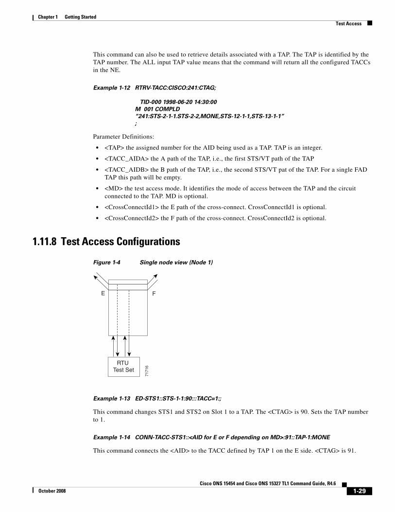
1.11.8 Test Access Configurations
Figure 1-4 Single node view (Node 1)
Example 1-13 ED-STS1::STS-1-1:90:::TACC=1:;
This command changes STS1 and STS2 on Slot 1 to a TAP. The <CTAG> is 90. Sets the TAP number to 1.
Example 1-14 CONN-TACC-STS1::<AID for E or F depending on MD>:91::TAP-1:MONE
This command connects the <AID> to the TACC defined by TAP 1 on the E side. <CTAG> is 91.
RTU
E F
Test Set
7171
6
1-29Cisco ONS 15454 and Cisco ONS 15327 TL1 Command Guide, R4.6
October 2008
Chapter 1 Getting StartedTest Access
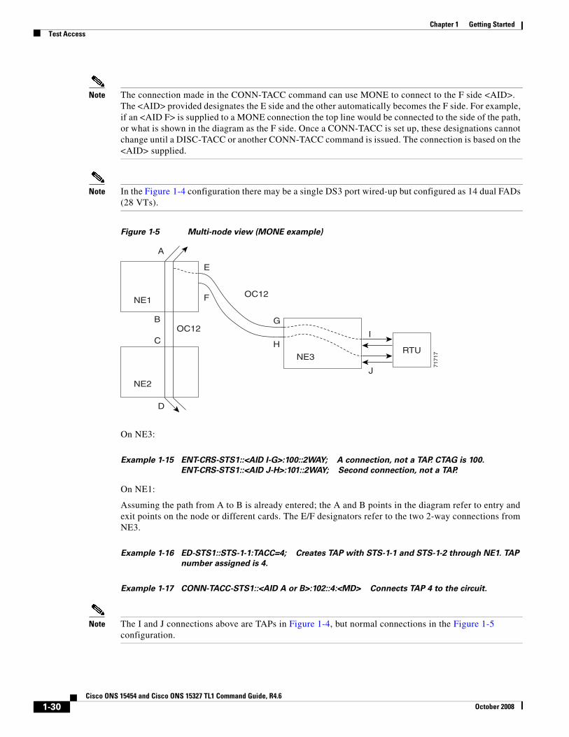
Note The connection made in the CONN-TACC command can use MONE to connect to the F side <AID>. The <AID> provided designates the E side and the other automatically becomes the F side. For example, if an <AID F> is supplied to a MONE connection the top line would be connected to the side of the path, or what is shown in the diagram as the F side. Once a CONN-TACC is set up, these designations cannot change until a DISC-TACC or another CONN-TACC command is issued. The connection is based on the <AID> supplied.
Note In the Figure 1-4 configuration there may be a single DS3 port wired-up but configured as 14 dual FADs (28 VTs).
Figure 1-5 Multi-node view (MONE example)
On NE3:
Example 1-15 ENT-CRS-STS1::<AID I-G>:100::2WAY; A connection, not a TAP. CTAG is 100.
ENT-CRS-STS1::<AID J-H>:101::2WAY; Second connection, not a TAP.
On NE1:
Assuming the path from A to B is already entered; the A and B points in the diagram refer to entry and exit points on the node or different cards. The E/F designators refer to the two 2-way connections from NE3.
Example 1-16 ED-STS1::STS-1-1:TACC=4; Creates TAP with STS-1-1 and STS-1-2 through NE1. TAP
number assigned is 4.
Example 1-17 CONN-TACC-STS1::<AID A or B>:102::4:<MD> Connects TAP 4 to the circuit.
Note The I and J connections above are TAPs in Figure 1-4, but normal connections in the Figure 1-5 configuration.
D
C
B
A
RTU
OC12
OC12
NE1
NE2
NE3
I
J
G
H
E
F
7171
7
1-30Cisco ONS 15454 and Cisco ONS 15327 TL1 Command Guide, R4.6
October 2008
Chapter 1 Getting StartedTest Access
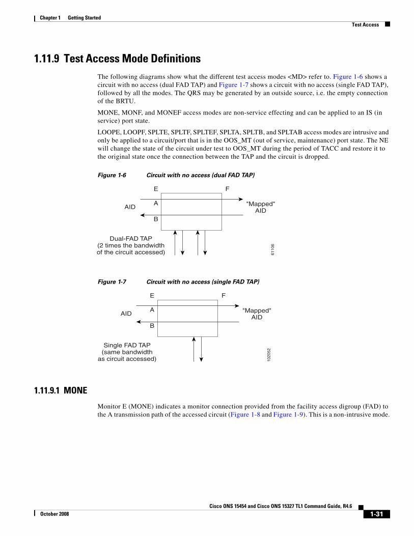
1.11.9 Test Access Mode DefinitionsThe following diagrams show what the different test access modes <MD> refer to. Figure 1-6 shows a circuit with no access (dual FAD TAP) and Figure 1-7 shows a circuit with no access (single FAD TAP), followed by all the modes. The QRS may be generated by an outside source, i.e. the empty connection of the BRTU.
MONE, MONF, and MONEF access modes are non-service effecting and can be applied to an IS (in service) port state.
LOOPE, LOOPF, SPLTE, SPLTF, SPLTEF, SPLTA, SPLTB, and SPLTAB access modes are intrusive and only be applied to a circuit/port that is in the OOS_MT (out of service, maintenance) port state. The NE will change the state of the circuit under test to OOS_MT during the period of TACC and restore it to the original state once the connection between the TAP and the circuit is dropped.
Figure 1-6 Circuit with no access (dual FAD TAP)
Figure 1-7 Circuit with no access (single FAD TAP)
1.11.9.1 MONE
Monitor E (MONE) indicates a monitor connection provided from the facility access digroup (FAD) to the A transmission path of the accessed circuit (Figure 1-8 and Figure 1-9). This is a non-intrusive mode.
6110
6
A
E
B
F
"Mapped"AID
AID
Dual-FAD TAP(2 times the bandwidthof the circuit accessed)
1020
52
A
E
B
F
"Mapped"AID
AID
Single FAD TAP(same bandwidth
as circuit accessed)
1-31Cisco ONS 15454 and Cisco ONS 15327 TL1 Command Guide, R4.6
October 2008
Chapter 1 Getting StartedTest Access
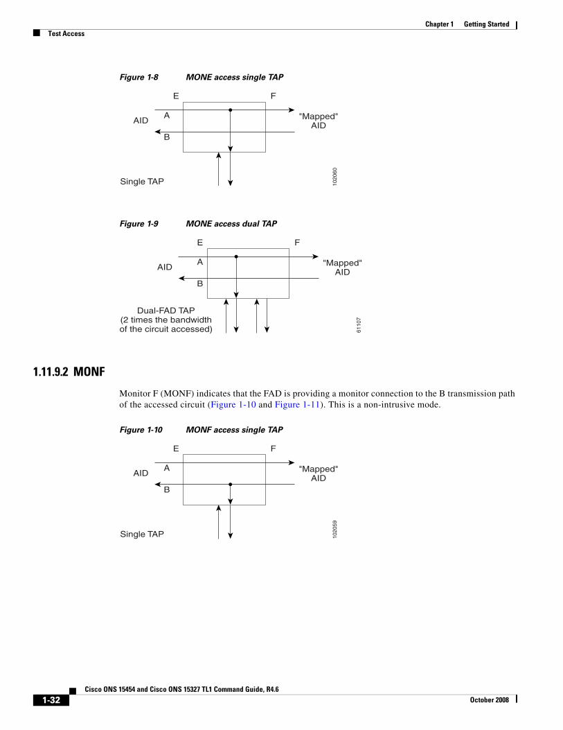
Figure 1-8 MONE access single TAP
Figure 1-9 MONE access dual TAP
1.11.9.2 MONF
Monitor F (MONF) indicates that the FAD is providing a monitor connection to the B transmission path of the accessed circuit (Figure 1-10 and Figure 1-11). This is a non-intrusive mode.
Figure 1-10 MONF access single TAP
1020
60
A
E
B
F
"Mapped"AID
AID
Single TAP
6110
7
A
E
B
F
"Mapped"AID
AID
Dual-FAD TAP(2 times the bandwidthof the circuit accessed)
1020
59
A
E
B
F
"Mapped"AID
AID
Single TAP
1-32Cisco ONS 15454 and Cisco ONS 15327 TL1 Command Guide, R4.6
October 2008
Chapter 1 Getting StartedTest Access
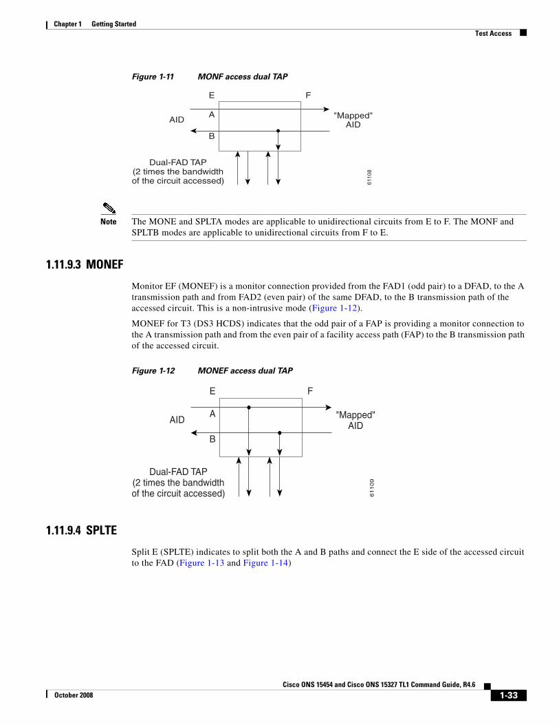
Figure 1-11 MONF access dual TAP
Note The MONE and SPLTA modes are applicable to unidirectional circuits from E to F. The MONF and SPLTB modes are applicable to unidirectional circuits from F to E.
1.11.9.3 MONEF
Monitor EF (MONEF) is a monitor connection provided from the FAD1 (odd pair) to a DFAD, to the A transmission path and from FAD2 (even pair) of the same DFAD, to the B transmission path of the accessed circuit. This is a non-intrusive mode (Figure 1-12).
MONEF for T3 (DS3 HCDS) indicates that the odd pair of a FAP is providing a monitor connection to the A transmission path and from the even pair of a facility access path (FAP) to the B transmission path of the accessed circuit.
Figure 1-12 MONEF access dual TAP
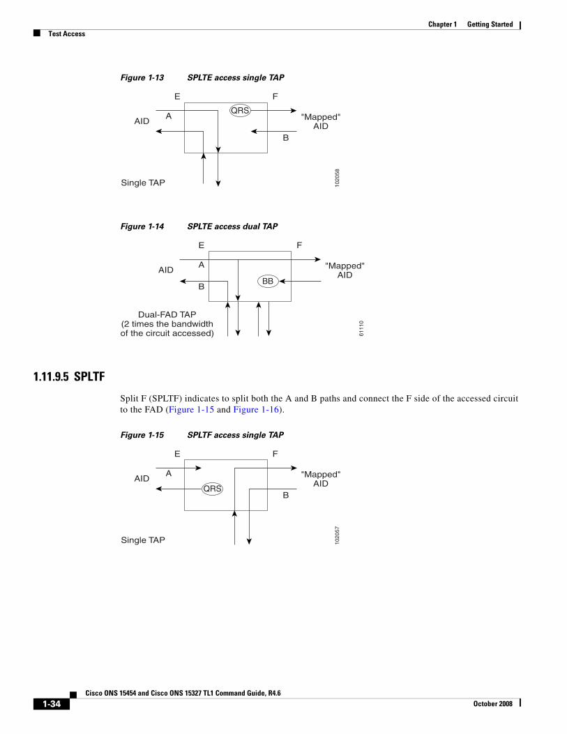
1.11.9.4 SPLTE
Split E (SPLTE) indicates to split both the A and B paths and connect the E side of the accessed circuit to the FAD (Figure 1-13 and Figure 1-14)
6110
8
A
E
B
F
"Mapped"AID
AID
Dual-FAD TAP(2 times the bandwidthof the circuit accessed)
61
10
9
A
E
B
F
"Mapped"AID
AID
Dual-FAD TAP(2 times the bandwidthof the circuit accessed)
1-33Cisco ONS 15454 and Cisco ONS 15327 TL1 Command Guide, R4.6
October 2008
Chapter 1 Getting StartedTest Access
Figure 1-13 SPLTE access single TAP
Figure 1-14 SPLTE access dual TAP
1.11.9.5 SPLTF
Split F (SPLTF) indicates to split both the A and B paths and connect the F side of the accessed circuit to the FAD (Figure 1-15 and Figure 1-16).
Figure 1-15 SPLTF access single TAP
1020
58
A
E
B
F
"Mapped"AID
AID
Single TAP
QRS
6111
0
A
E
B
F
"Mapped"AID
AID
Dual-FAD TAP(2 times the bandwidthof the circuit accessed)
BB
1020
57
A
E
B
F
"Mapped"AID
AID
Single TAP
QRS
1-34Cisco ONS 15454 and Cisco ONS 15327 TL1 Command Guide, R4.6
October 2008
Chapter 1 Getting StartedTest Access
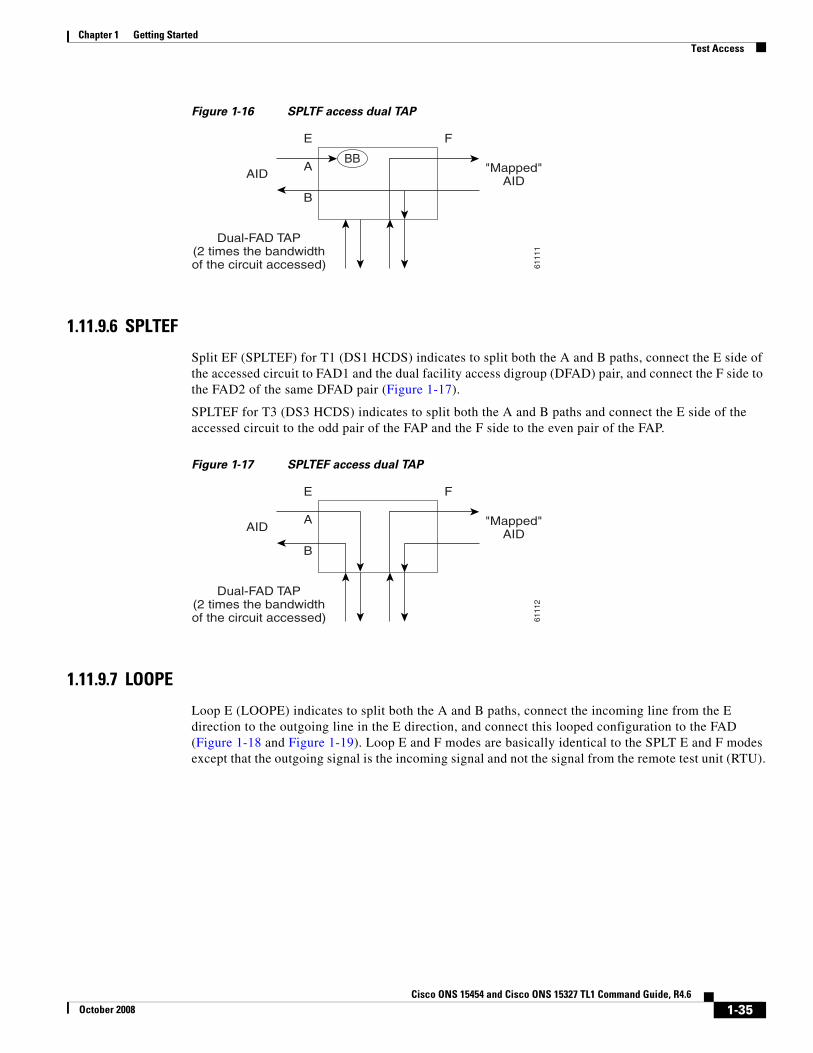
Figure 1-16 SPLTF access dual TAP
1.11.9.6 SPLTEF
Split EF (SPLTEF) for T1 (DS1 HCDS) indicates to split both the A and B paths, connect the E side of the accessed circuit to FAD1 and the dual facility access digroup (DFAD) pair, and connect the F side to the FAD2 of the same DFAD pair (Figure 1-17).
SPLTEF for T3 (DS3 HCDS) indicates to split both the A and B paths and connect the E side of the accessed circuit to the odd pair of the FAP and the F side to the even pair of the FAP.
Figure 1-17 SPLTEF access dual TAP
1.11.9.7 LOOPE
Loop E (LOOPE) indicates to split both the A and B paths, connect the incoming line from the E direction to the outgoing line in the E direction, and connect this looped configuration to the FAD (Figure 1-18 and Figure 1-19). Loop E and F modes are basically identical to the SPLT E and F modes except that the outgoing signal is the incoming signal and not the signal from the remote test unit (RTU).
6111
1
A
E
B
F
"Mapped"AID
AID
Dual-FAD TAP(2 times the bandwidthof the circuit accessed)
BB
6111
2
A
E
B
F
"Mapped"AID
AID
Dual-FAD TAP(2 times the bandwidthof the circuit accessed)
1-35Cisco ONS 15454 and Cisco ONS 15327 TL1 Command Guide, R4.6
October 2008
Chapter 1 Getting StartedTest Access
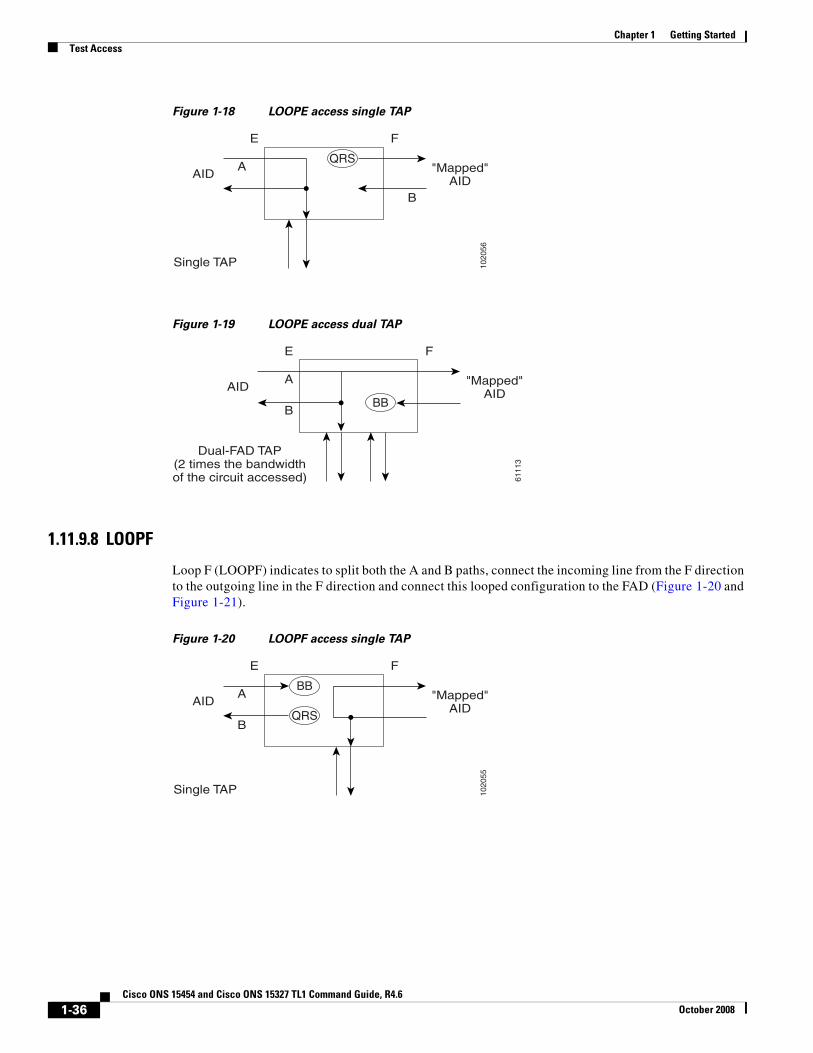
Figure 1-18 LOOPE access single TAP
Figure 1-19 LOOPE access dual TAP
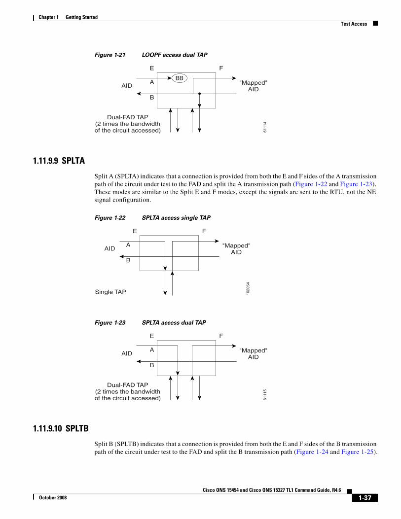
1.11.9.8 LOOPF
Loop F (LOOPF) indicates to split both the A and B paths, connect the incoming line from the F direction to the outgoing line in the F direction and connect this looped configuration to the FAD (Figure 1-20 and Figure 1-21).
Figure 1-20 LOOPF access single TAP
1020
56
A
E
B
F
"Mapped"AID
AID
Single TAP
QRS
6111
3
A
E
B
F
"Mapped"AID
AID
Dual-FAD TAP(2 times the bandwidthof the circuit accessed)
BB
1020
55
A
E
B
F
"Mapped"AID
AID
Single TAP
BB
QRS
1-36Cisco ONS 15454 and Cisco ONS 15327 TL1 Command Guide, R4.6
October 2008
Chapter 1 Getting StartedTest Access
Figure 1-21 LOOPF access dual TAP
1.11.9.9 SPLTA
Split A (SPLTA) indicates that a connection is provided from both the E and F sides of the A transmission path of the circuit under test to the FAD and split the A transmission path (Figure 1-22 and Figure 1-23). These modes are similar to the Split E and F modes, except the signals are sent to the RTU, not the NE signal configuration.
Figure 1-22 SPLTA access single TAP
Figure 1-23 SPLTA access dual TAP
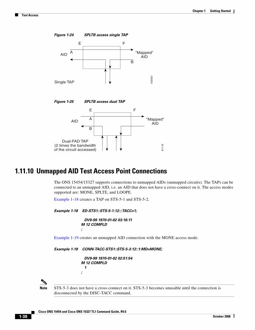
1.11.9.10 SPLTB
Split B (SPLTB) indicates that a connection is provided from both the E and F sides of the B transmission path of the circuit under test to the FAD and split the B transmission path (Figure 1-24 and Figure 1-25).
6111
4
A
E
B
F
"Mapped"AID
AID
Dual-FAD TAP(2 times the bandwidthof the circuit accessed)
BB
1020
54A
E
B
F
"Mapped"AID
AID
Single TAP
6111
5
A
E
B
F
"Mapped"AID
AID
Dual-FAD TAP(2 times the bandwidthof the circuit accessed)
1-37Cisco ONS 15454 and Cisco ONS 15327 TL1 Command Guide, R4.6
October 2008
Chapter 1 Getting StartedTest Access
Figure 1-24 SPLTB access single TAP
Figure 1-25 SPLTB access dual TAP
1.11.10 Unmapped AID Test Access Point ConnectionsThe ONS 15454/15327 supports connections to unmapped AIDs (unmapped circuits). The TAPs can be connected to an unmapped AID, i.e. an AID that does not have a cross-connect on it. The access modes supported are: MONE, SPLTE, and LOOPE.
Example 1-18 creates a TAP on STS-5-1 and STS-5-2.
Example 1-18 ED-STS1::STS-5-1:12:::TACC=1;
DV9-99 1970-01-02 03:16:11
M 12 COMPLD
;
Example 1-19 creates an unmapped AID connection with the MONE access mode.
Example 1-19 CONN-TACC-STS1::STS-5-3:12::1:MD=MONE;
DV9-99 1970-01-02 02:51:54
M 12 COMPLD
1
;
Note STS-5-3 does not have a cross-connect on it. STS-5-3 becomes unusable until the connection is disconnected by the DISC-TACC command.
1020
53
A
E
B
F
"Mapped"AID
AID
Single TAP
6111
6
A
E
B
F
"Mapped"AID
AID
Dual-FAD TAP(2 times the bandwidthof the circuit accessed)
1-38Cisco ONS 15454 and Cisco ONS 15327 TL1 Command Guide, R4.6
October 2008
Chapter 1 Getting StartedTest Access
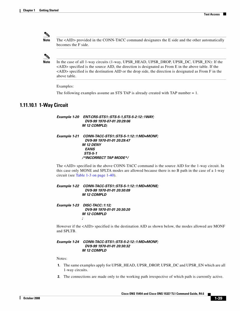
Note The <AID> provided in the CONN-TACC command designates the E side and the other automatically becomes the F side.
Note In the case of all 1-way circuits (1-way, UPSR_HEAD, UPSR_DROP, UPSR_DC, UPSR_EN): If the <AID> specified is the source AID, the direction is designated as From E in the above table. If the <AID> specified is the destination AID or the drop side, the direction is designated as From F in the above table.
Examples:
The following examples assume an STS TAP is already created with TAP number = 1.
1.11.10.1 1-Way Circuit
Example 1-20 ENT-CRS-STS1::STS-5-1,STS-5-2:12::1WAY;
DV9-99 1970-07-01 20:29:06
M 12 COMPLD;
Example 1-21 CONN-TACC-STS1::STS-5-1:12::1:MD=MONF;
DV9-99 1970-01-01 20:29:47
M 12 DENY
EANS
STS-5-1
/*INCORRECT TAP MODE*/
The <AID> specified in the above CONN-TACC command is the source AID for the 1-way circuit. In this case only MONE and SPLTA modes are allowed because there is no B path in the case of a 1-way circuit (see Table 1-3 on page 1-40).
Example 1-22 CONN-TACC-STS1::STS-5-1:12::1:MD=MONE;
DV9-99 1970-01-01 20:30:09
M 12 COMPLD
Example 1-23 DISC-TACC::1:12;
DV9-99 1970-01-01 20:30:20
M 12 COMPLD
;
However if the <AID> specified is the destination AID as shown below, the modes allowed are MONF and SPLTB.
Example 1-24 CONN-TACC-STS1::STS-5-2:12::1:MD=MONF;
DV9-99 1970-01-01 20:30:32
M 12 COMPLD
Notes:
1. The same examples apply for UPSR_HEAD, UPSR_DROP, UPSR_DC and UPSR_EN which are all 1-way circuits.
2. The connections are made only to the working path irrespective of which path is currently active.
1-39Cisco ONS 15454 and Cisco ONS 15327 TL1 Command Guide, R4.6
October 2008
Chapter 1 Getting StartedTest Access
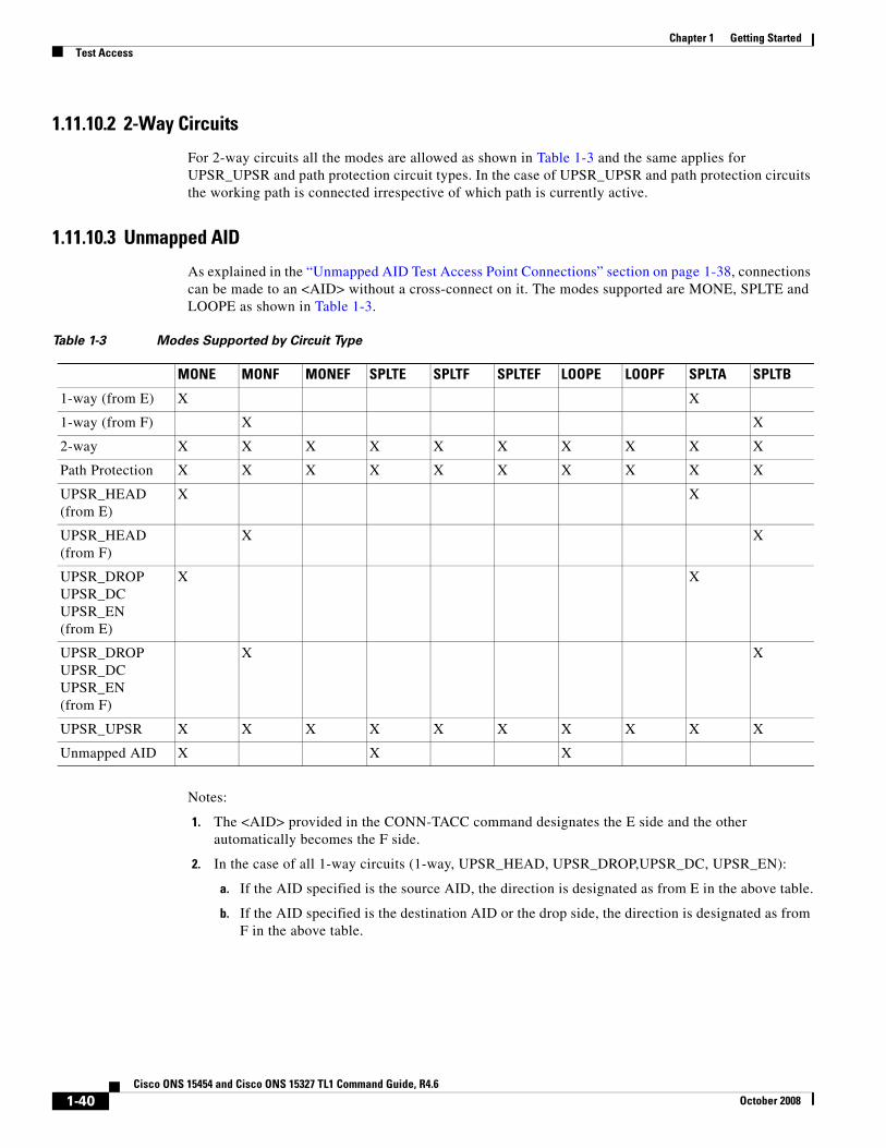
1.11.10.2 2-Way Circuits
For 2-way circuits all the modes are allowed as shown in Table 1-3 and the same applies for UPSR_UPSR and path protection circuit types. In the case of UPSR_UPSR and path protection circuits the working path is connected irrespective of which path is currently active.
1.11.10.3 Unmapped AID
As explained in the “Unmapped AID Test Access Point Connections” section on page 1-38, connections can be made to an <AID> without a cross-connect on it. The modes supported are MONE, SPLTE and LOOPE as shown in Table 1-3.
Notes:
1. The <AID> provided in the CONN-TACC command designates the E side and the other automatically becomes the F side.
2. In the case of all 1-way circuits (1-way, UPSR_HEAD, UPSR_DROP,UPSR_DC, UPSR_EN):
a. If the AID specified is the source AID, the direction is designated as from E in the above table.
b. If the AID specified is the destination AID or the drop side, the direction is designated as from F in the above table.
Table 1-3 Modes Supported by Circuit Type
MONE MONF MONEF SPLTE SPLTF SPLTEF LOOPE LOOPF SPLTA SPLTB
1-way (from E) X X
1-way (from F) X X
2-way X X X X X X X X X X
Path Protection X X X X X X X X X X
UPSR_HEAD (from E)
X X
UPSR_HEAD (from F)
X X
UPSR_DROPUPSR_DCUPSR_EN(from E)
X X
UPSR_DROPUPSR_DCUPSR_EN(from F)
X X
UPSR_UPSR X X X X X X X X X X
Unmapped AID X X X
1-40Cisco ONS 15454 and Cisco ONS 15327 TL1 Command Guide, R4.6
October 2008
Chapter 1 Getting StartedTL1 PCA Provisioning
1.12 TL1 PCA ProvisioningYou can provision or retrieve protection channel access (PCA) cross-connections on two-fiber and four-fiber BLSR topologies at these supported OC rates: OC12 (two-fiber only), OC48, and OC192. The traffic on the protection channel is referred to as extra-traffic and has the lowest priority level. Extra-traffic will be preempted by any working traffic that requires the use of the protection channel.
In a two-fiber BLSR the extra traffic is provisioned on the upper half of the bandwidth path. In a four-fiber BLSR the extra traffic is provisioned on the protect fiber. The PCA provisioning feature allows you to establish the PCA cross-connection on the protection path of the two-fiber BLSR and protection channel of the four-fiber BLSR only when the query is an explicit request.
There are two PCA connection types: 1WAYPCA and 2WAYPCA. The PCA cross-connection is provisioned only when the user provides an explicit request using the ENT-CRS-STSp/VT1 commands. If the cross-connection is a PCA cross-connection, either 1WAYPCA or 2WAYPCA is shown in the CCT field of the RTRV-CRS-STSp/VT1 command output.
1WAYPCA and 2WAYPCA are only used in the TL1 user interface to provide usability and visibility for the user to specify a PCA cross-connection type in the TL1 cross-connection commands.
Note The network must be configured as either a two-fiber or four-fiber OC-12, OC-48, or OC-192 BLSR.
Note The STS or VT1 path cross-connection can be established with TL1 commands (ENT-CRS-xxx).
Note Because the RTRV-CSR-xxx command does not include the optional CTYPE field to specify a connection type, the output result reports the matched cross-connections based on the queried AID(s); therefore, the retrieved cross-connection inventory can be both PCA and non-PCA cross-connections.
1.12.1 Provision a PCA Cross-ConnectionInput format for provisioning a PCA cross-connection:
Example 1-25 ENT-CRS-<PATH>:[<TID>]:<FROM>,<TO>:<CTAG>::[<CCT>][::];
<PATH>::={STS_PATH | VT1}
[<CCT>]::={1WAY, 1WAYDC, 1WAYEN, 2WAY, 1WAYPCA, 2WAYPCA}, it defaults to 2WAY.
{STS_PATH}::={STS1 | STS3C | STS6C | STS9C | STS12C | STS24C | STS48C | STS192C}
STS= all the STS bandwidth cross-connections.
VT1=VT1_5 cross-connection.
Input example of provisioning an STS3C PCA cross-connection:
Example 1-26 ENT-CRS-STS3C::STS-1-1,STS-2-1:123::2WAYPCA;
Note If the [<CCT>] of this cross-connection provisioning command is either 1WAYPCA or 2WAYPCA, and the NONE of both <FROM> and <TO> AID is PCA AID, an IIAC ( Input, Invalid PCA AIDs) error message is returned.
1-41Cisco ONS 15454 and Cisco ONS 15327 TL1 Command Guide, R4.6
October 2008
Chapter 1 Getting StartedFTP Software Download
Note If sending this command with a non-PCA connection type (CCT), and one (or two) AIDs is/are the PCA AIDs, an IIAC (The PCA AID Is Not Allowed for the Queried CCT Type) error message is returned.
1.12.2 Retrieve a PCA Cross-ConnectionInput Format for retrieving a PCA cross-connection:
Example 1-27 RTRV-CRS-[<PATH>]:[<TID>]:<AID>:<CTAG>[::::];<PATH>::=
{STS_PATH | VT1 | STS}
If PATH is STS, it will retrieve all the STS cross-connections based on the queried AIDs.
<AID>={FacilityAIDs, STSAIDs, VTAIDs, ALL}
Output format of the PCA STSp cross-connection retrieval command:
Example 1-28 “<FROM>,<TO>:2WAYPCA,STS3C”
Output format of the PCA VT cross-connection retrieval command:
Example 1-29 “<FROM>,<TO>:2WAYPCA”
1.13 FTP Software DownloadThe file transfer protocol (FTP) software download feature downloads a software package to the inactive flash partition residing on either the TCC2 or XTC card. FTP software download provides for simplex and duplex TCC2 or XTC card downloads, success and failure status, and in-progress status at 20% increments.
1.13.1 COPY-RFILEThe COPY-RFILE command downloads a new software package from the location specified by the FTP URL into the inactive flash partition residing on either the TCC2 or XTC card.
Input format:
Example 1-30 COPY-RFILE:[<TID>]:[<SRC>]:<CTAG>::TYPE=<XFERTYPE>,[SRC=<SRC1>,]
[DEST=<DEST>,][OVWRT=<OVWRT>];
where:
• SRC is the type of file being transferred and is from the “RFILE” section on page 4-31
• <XFERTYPE> is the file transfer protocol; valid values can be found in the “TX_TYPE” section on page 4-95
• <SRC1> specifies the source of the file to be transferred. Only the FTP URL is supported. In a non-firewall environment the format for the URL is: “FTP://FTTPUSER[:FTP_PASSWORD]]@FTP_HOST_IP[:21]/PACKAGE_PATH[:TYPE=I]”
where:
1-42Cisco ONS 15454 and Cisco ONS 15327 TL1 Command Guide, R4.6
October 2008
Chapter 1 Getting StartedFTP Software Download
– FTP_USER is the userid to connect to the computer with the package file
– FTP_PASSWORD is the password used to connect to the computer with the package file
– FTP_HOST_IP is the IP address of the computer with the package file, DNS lookup of hostnames is not supported
– PACKAGE_PATH is the long path name to the package file
Note Userid and password are optional if the user does not need to log into the host computer. The password may be optional if the user does not need to log in. All other portions of the URL are required, including the initial “FTP://” string.
In a firewall environment the hostname should be replaced with a list of IP addresses each separated by a “@” character. The first IP address should be for the computer where the package file is stored. Subsequent IP addresses are for firewall computers moving outward toward the edge of the network until the final IP address listed is the computer that outside users use to first access the network.
For example, if your topology is:
“FTPHOST <-> GNE3 <->GNE2 <-> GNE1 <-> ENE”
the FTP URL is:
FTP://FTP_USER:FTP_PASSWORD@FTP_HOST_IP@GNE3@GNE2@GNE1/PACKAGE_PATH
SRC1 is a String
– DEST specifies the destination of the file to be transferred. The comments for the SRC parameter are also valid here. DEST is a string
– If OVWRT is YES, then files are overwritten. Currently only YES is supported. Using a NO value for OVWRT will result in an error message. Valid values are shown in the 4.5.140 YES_NO, page 4-99
Notes:
1. SWDL is the only allowable <XFERTYPE>.
2. FTP is the only allowed file transfer method.
3. The use of the SWDL and the extended FTP URL syntax are required by the COPY-RFILE syntax.
1.13.2 APPLYThe APPLY command can activate or revert software depending on the version of software loaded on the active and protect flash. An error is returned if attempting to activate to an older software load or trying to revert to a newer software load. If this command is successful the appropriate flash is selected and the TCC2 or XTC card will reboot.
Input format:
Example 1-31 APPLY:[<TID>]::<CTAG>[::<MEM_SW_TYPE>]:
where:
• <MEM_SW_TYPE> indicates memory switch action during the software upgrade. Valid values are shown in the 4.5.31 DL_TYPE, page 4-57
1-43Cisco ONS 15454 and Cisco ONS 15327 TL1 Command Guide, R4.6
October 2008
Chapter 1 Getting StartedFTP Software Download
1.13.3 REPT EVT FXFRREPT EVT FXFR is an autonomous message used to report the start, completion, and completed percentage status of the FTP software download. REPT EVT FXFR also reports any failure during the software upgrade including invalid package, invalid path, invalid userid/password, and loss of network connection.
Note:
1. The “FXFR_RSLT” is only sent when the “FXFR_STATUS” is COMPLD.
2. The “BYTES_XFRD” is only sent when the “FXFR_STATUS” is IP or COMPLD.
Output format:
Example 1-32 SID DATE TIME
A ATAG REPT EVT FXFR
“<FILENAME>,<FXFR_STATUS>,[<FXFR_RSLT>],[<BYTES_XFRD>]”
;
where:
• <FILENAME> indicates the transferred file path name and is a string. When a package is being transferred between the FTP server and the controller cards, the filename field will contain the string “active”. Following this transfer, if there is a second controller card on the node, the file will be copied over to the second card. While this is happening, REPT EVT FXFR messages will be generated with a filename of “standby”.
• <FXFR_STATUS> indicates the file transferred status: Start, IP (in progress), or COMPLD. Valid values are shown in the 4.5.123 TX_STATUS, page 4-94
• <FXFR_RSLT> indicates the file transferred result: success or failure. <FXFR_RSLT> is optional and valid values are shown in the 4.5.122 TX_RSLT, page 4-94
• <BYTES_XFRD> indicates the transferred byte count. <BYTES_XFRD> is a string and is optional
1.13.4 Downloading New SoftwareThe following procedure downloads new software to the TCC2 or XTC card using TL1.
Download New Software
Note Only Superusers can download and activate software.
Step 1 Copy the new software package (15454-0340-X02E-2804.pkg) to an FTP host.
Step 2 Establish a TL1 session with the target NE.
Step 3 Login with the ACT-USER command.
Step 4 Check the working and protect software on the NE by issuing the RTRV-NE-GEN command.
Input example:
1-44Cisco ONS 15454 and Cisco ONS 15327 TL1 Command Guide, R4.6
October 2008
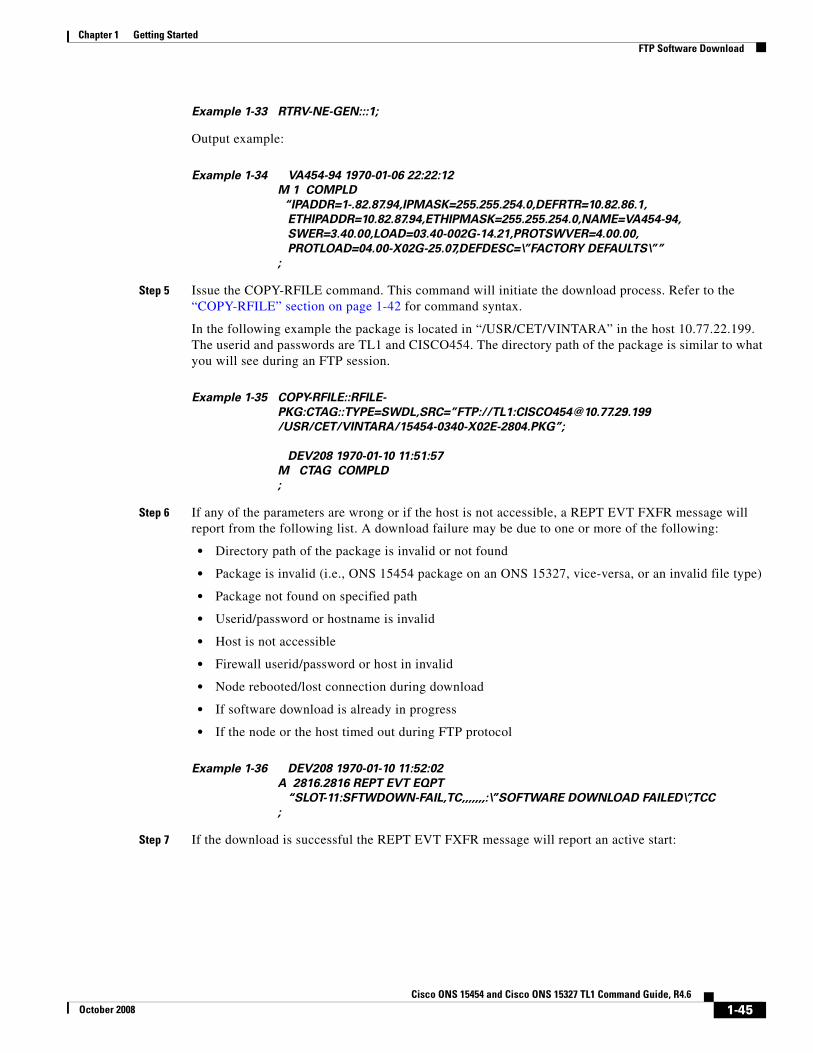
Chapter 1 Getting StartedFTP Software Download
Example 1-33 RTRV-NE-GEN:::1;
Output example:
Example 1-34 VA454-94 1970-01-06 22:22:12
M 1 COMPLD
“IPADDR=1-.82.87.94,IPMASK=255.255.254.0,DEFRTR=10.82.86.1,
ETHIPADDR=10.82.87.94,ETHIPMASK=255.255.254.0,NAME=VA454-94,
SWER=3.40.00,LOAD=03.40-002G-14.21,PROTSWVER=4.00.00,
PROTLOAD=04.00-X02G-25.07,DEFDESC=\”FACTORY DEFAULTS\””
;
Step 5 Issue the COPY-RFILE command. This command will initiate the download process. Refer to the “COPY-RFILE” section on page 1-42 for command syntax.
In the following example the package is located in “/USR/CET/VINTARA” in the host 10.77.22.199. The userid and passwords are TL1 and CISCO454. The directory path of the package is similar to what you will see during an FTP session.
Example 1-35 COPY-RFILE::RFILE-
PKG:CTAG::TYPE=SWDL,SRC=”FTP://TL1:[email protected]
/USR/CET/VINTARA/15454-0340-X02E-2804.PKG”;
DEV208 1970-01-10 11:51:57
M CTAG COMPLD
;
Step 6 If any of the parameters are wrong or if the host is not accessible, a REPT EVT FXFR message will report from the following list. A download failure may be due to one or more of the following:
• Directory path of the package is invalid or not found
• Package is invalid (i.e., ONS 15454 package on an ONS 15327, vice-versa, or an invalid file type)
• Package not found on specified path
• Userid/password or hostname is invalid
• Host is not accessible
• Firewall userid/password or host in invalid
• Node rebooted/lost connection during download
• If software download is already in progress
• If the node or the host timed out during FTP protocol
Example 1-36 DEV208 1970-01-10 11:52:02
A 2816.2816 REPT EVT EQPT
“SLOT-11:SFTWDOWN-FAIL,TC,,,,,,,:\”SOFTWARE DOWNLOAD FAILED\”,TCC
;
Step 7 If the download is successful the REPT EVT FXFR message will report an active start:
1-45Cisco ONS 15454 and Cisco ONS 15327 TL1 Command Guide, R4.6
October 2008
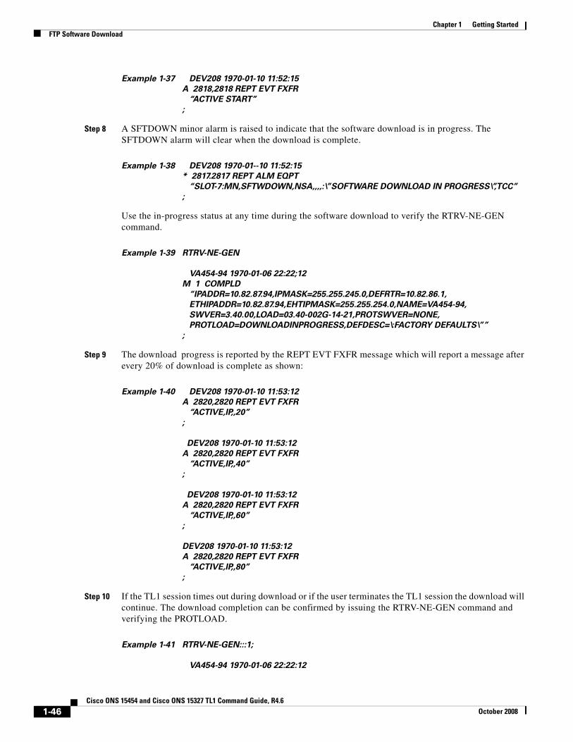
Chapter 1 Getting StartedFTP Software Download
Example 1-37 DEV208 1970-01-10 11:52:15
A 2818,2818 REPT EVT FXFR
“ACTIVE START”
;
Step 8 A SFTDOWN minor alarm is raised to indicate that the software download is in progress. The SFTDOWN alarm will clear when the download is complete.
Example 1-38 DEV208 1970-01--10 11:52:15
* 2817.2817 REPT ALM EQPT
“SLOT-7:MN,SFTWDOWN,NSA,,,,:\”SOFTWARE DOWNLOAD IN PROGRESS\”,TCC”
;
Use the in-progress status at any time during the software download to verify the RTRV-NE-GEN command.
Example 1-39 RTRV-NE-GEN
VA454-94 1970-01-06 22:22;12
M 1 COMPLD
“IPADDR=10.82.87.94,IPMASK=255.255.245.0,DEFRTR=10.82.86.1,
ETHIPADDR=10.82.87.94,EHTIPMASK=255.255.254.0,NAME=VA454-94,
SWVER=3.40.00,LOAD=03.40-002G-14-21,PROTSWVER=NONE,
PROTLOAD=DOWNLOADINPROGRESS,DEFDESC=\:FACTORY DEFAULTS\””
;
Step 9 The download progress is reported by the REPT EVT FXFR message which will report a message after every 20% of download is complete as shown:
Example 1-40 DEV208 1970-01-10 11:53:12
A 2820,2820 REPT EVT FXFR
“ACTIVE,IP,,20”
;
DEV208 1970-01-10 11:53:12
A 2820,2820 REPT EVT FXFR
“ACTIVE,IP,,40”
;
DEV208 1970-01-10 11:53:12
A 2820,2820 REPT EVT FXFR
“ACTIVE,IP,,60”
;
DEV208 1970-01-10 11:53:12
A 2820,2820 REPT EVT FXFR
“ACTIVE,IP,,80”
;
Step 10 If the TL1 session times out during download or if the user terminates the TL1 session the download will continue. The download completion can be confirmed by issuing the RTRV-NE-GEN command and verifying the PROTLOAD.
Example 1-41 RTRV-NE-GEN:::1;
VA454-94 1970-01-06 22:22:12
1-46Cisco ONS 15454 and Cisco ONS 15327 TL1 Command Guide, R4.6
October 2008
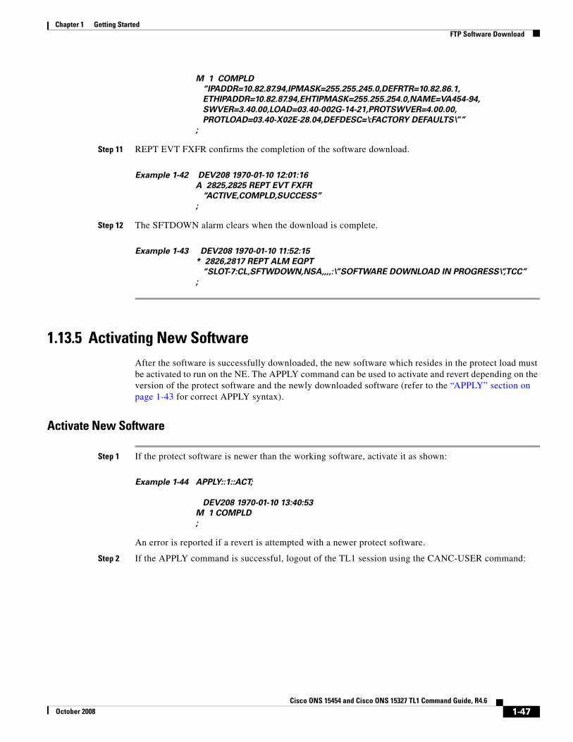
Chapter 1 Getting StartedFTP Software Download
M 1 COMPLD
“IPADDR=10.82.87.94,IPMASK=255.255.245.0,DEFRTR=10.82.86.1,
ETHIPADDR=10.82.87.94,EHTIPMASK=255.255.254.0,NAME=VA454-94,
SWVER=3.40.00,LOAD=03.40-002G-14-21,PROTSWVER=4.00.00,
PROTLOAD=03.40-X02E-28.04,DEFDESC=\:FACTORY DEFAULTS\””
;
Step 11 REPT EVT FXFR confirms the completion of the software download.
Example 1-42 DEV208 1970-01-10 12:01:16
A 2825,2825 REPT EVT FXFR
“ACTIVE,COMPLD,SUCCESS”
;
Step 12 The SFTDOWN alarm clears when the download is complete.
Example 1-43 DEV208 1970-01-10 11:52:15
* 2826,2817 REPT ALM EQPT
“SLOT-7:CL,SFTWDOWN,NSA,,,,:\”SOFTWARE DOWNLOAD IN PROGRESS\”,TCC”
;
1.13.5 Activating New SoftwareAfter the software is successfully downloaded, the new software which resides in the protect load must be activated to run on the NE. The APPLY command can be used to activate and revert depending on the version of the protect software and the newly downloaded software (refer to the “APPLY” section on page 1-43 for correct APPLY syntax).
Activate New Software
Step 1 If the protect software is newer than the working software, activate it as shown:
Example 1-44 APPLY::1::ACT;
DEV208 1970-01-10 13:40:53
M 1 COMPLD
;
An error is reported if a revert is attempted with a newer protect software.
Step 2 If the APPLY command is successful, logout of the TL1 session using the CANC-USER command:
1-47Cisco ONS 15454 and Cisco ONS 15327 TL1 Command Guide, R4.6
October 2008
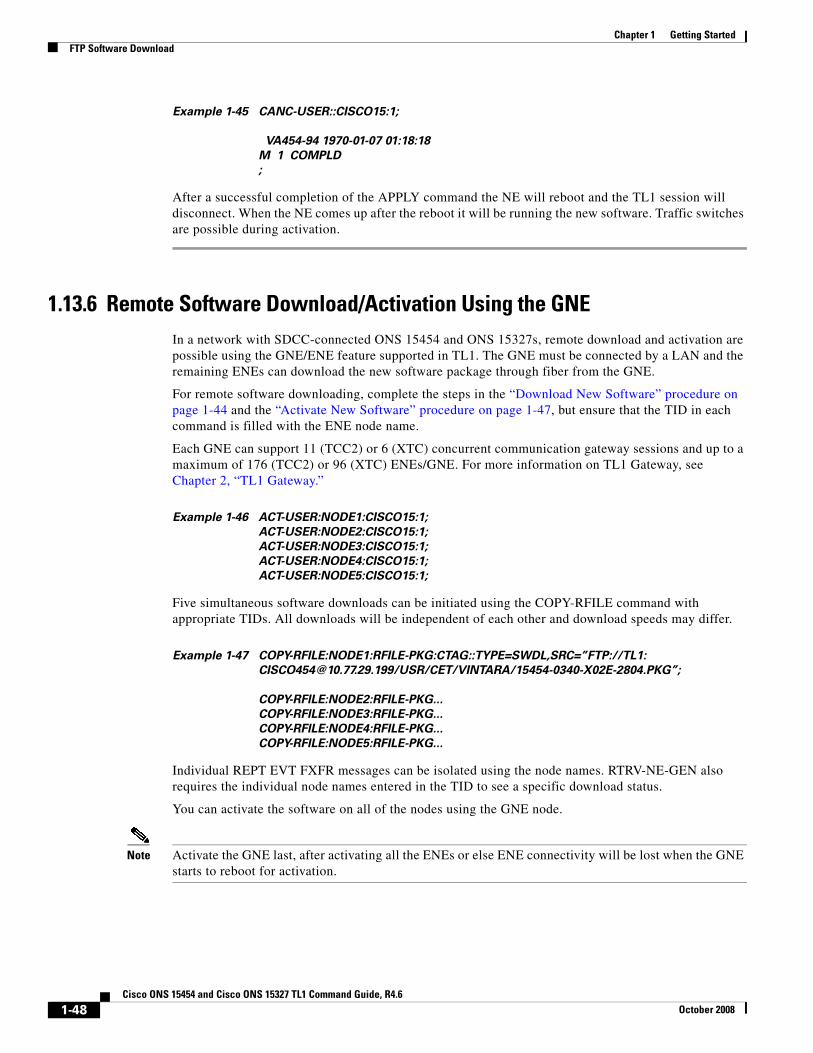
Chapter 1 Getting StartedFTP Software Download
Example 1-45 CANC-USER::CISCO15:1;
VA454-94 1970-01-07 01:18:18
M 1 COMPLD
;
After a successful completion of the APPLY command the NE will reboot and the TL1 session will disconnect. When the NE comes up after the reboot it will be running the new software. Traffic switches are possible during activation.
1.13.6 Remote Software Download/Activation Using the GNEIn a network with SDCC-connected ONS 15454 and ONS 15327s, remote download and activation are possible using the GNE/ENE feature supported in TL1. The GNE must be connected by a LAN and the remaining ENEs can download the new software package through fiber from the GNE.
For remote software downloading, complete the steps in the “Download New Software” procedure on page 1-44 and the “Activate New Software” procedure on page 1-47, but ensure that the TID in each command is filled with the ENE node name.
Each GNE can support 11 (TCC2) or 6 (XTC) concurrent communication gateway sessions and up to a maximum of 176 (TCC2) or 96 (XTC) ENEs/GNE. For more information on TL1 Gateway, see Chapter 2, “TL1 Gateway.”
Example 1-46 ACT-USER:NODE1:CISCO15:1;
ACT-USER:NODE2:CISCO15:1;
ACT-USER:NODE3:CISCO15:1;
ACT-USER:NODE4:CISCO15:1;
ACT-USER:NODE5:CISCO15:1;
Five simultaneous software downloads can be initiated using the COPY-RFILE command with appropriate TIDs. All downloads will be independent of each other and download speeds may differ.
Example 1-47 COPY-RFILE:NODE1:RFILE-PKG:CTAG::TYPE=SWDL,SRC=”FTP://TL1:
[email protected]/USR/CET/VINTARA/15454-0340-X02E-2804.PKG”;
COPY-RFILE:NODE2:RFILE-PKG...
COPY-RFILE:NODE3:RFILE-PKG...
COPY-RFILE:NODE4:RFILE-PKG...
COPY-RFILE:NODE5:RFILE-PKG...
Individual REPT EVT FXFR messages can be isolated using the node names. RTRV-NE-GEN also requires the individual node names entered in the TID to see a specific download status.
You can activate the software on all of the nodes using the GNE node.
Note Activate the GNE last, after activating all the ENEs or else ENE connectivity will be lost when the GNE starts to reboot for activation.
1-48Cisco ONS 15454 and Cisco ONS 15327 TL1 Command Guide, R4.6
October 2008

Chapter 1 Getting StartedFTP Software Download
Example 1-48 APPLY:NODE1::1::ACT;
APPLY:NODE2::1::ACT;
APPLY:NODE3::1::ACT;
APPLY:NODE4::1::ACT;
APPLY:NODE5::1::ACT;
1-49Cisco ONS 15454 and Cisco ONS 15327 TL1 Command Guide, R4.6
October 2008

Chapter 1 Getting StartedFTP Software Download
1-50Cisco ONS 15454 and Cisco ONS 15327 TL1 Command Guide, R4.6
October 2008