geosynthetics and reinforced soil structures prof. k....
TRANSCRIPT

Geosynthetics and Reinforced Soil StructuresProf. K. Rajagopal
Department of Civil EngineeringIndian Institute of Technology, Madras
Lecture - 21Geosynthetic Reinforced Soil Embankments – I
Good morning students. In the previous lectures, we have seen how to design
vertical retaining walls. And now let us look at how to design the embankments or
slopes.
(Refer Slide Time:00:24)
Well, what are the design approaches and especially when it comes to definition
what is an embankment, and what is a wall? Slopes that are steeper than seventy
degrees are designed as a retaining walls. And the slopes that are shallower than
seventy degrees are designed as slopes, and we will see some of the principles
applicable for these, for the design of slopes in the lectures to follow.

(Refer Slide Time:00:57)
Here is an example of an extreme case of a slope, it is the airport that is being
constructed at Sikkim. This is the view, this is the schematic view of the airport
runway and this being a hilly terrain, there is no flat ground. And we need to
make up a ground, and in order to make up, engineers had to build up this
slope all around these dotted lines all around and the cross section, you can see
here, the height is about nearly 110 meters it is a very steep faced embankment
as you can see, and it is one of the most challenging projects that has ever
been taken up in India and this work is being carried out by Macca Ferri, India.
(Refer Slide Time:01:59)
Well, whenever we have an embankment or a slope as you can see
on the road sides or railway embankments, the surface is free to the
rain water or window erosion and so on. And how do we protect the
surface on the slopes, there are different methods the best method is
by far growing the vegetation. And we can use erosion control mats
like coir mat, jute or crimped mesh and so on or we can use stone
pitching, but the effectiveness of the stone pitching is doubtful
especially, when your face is very steep, the stones may start falling
down just simply creeping down because of several reasons or we
can use spray concrete on surface or we can give gabion facings and
so on.
(Refer Slide Time:02:59)
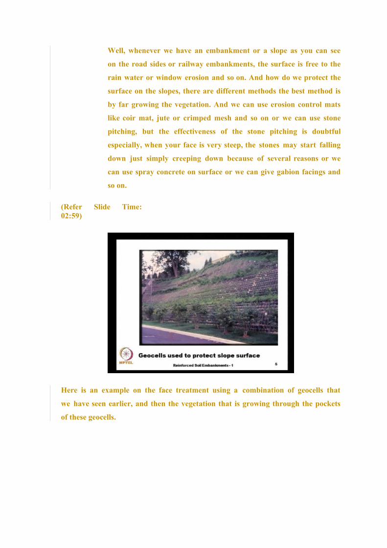
Here is an example on the face treatment using a combination of geocells that
we have seen earlier, and then the vegetation that is growing through the pockets
of these geocells.

(Refer Slide Time:03:15)
And here is an example of a crimped mesh, and a polymeric textile that can be
used to protect the surface of this slopes.
(Refer Slide Time:03:29)
And these are different examples of coir and jute that can be used for
controlling erosion on the slopes, the rain water induced erosion usually
results in gulley formation like this, that we frequently see on the on the Indian
roads and embankments. And once it is treated with a coir or jute cover and if we
can promote the vegetation the surface look something like this is actually in the
inside, you can see at the coir mat that

is exposed and by far the growth of vegetation is the best solution for controlling
the erosion on the slopes.
(Refer Slide Time:04:16)
And here we see an example of using spray concrete, and sometimes the spray
concrete may not stay on the surface on the slope surface especially if the slope
is very steep. In such cases, we use the geocells which are the three dimensional
form of geosynthetics that we have seen earlier, we can spread them and fill these
pockets with cement concrete so that we provide a good erosion control on the
surface, and this particular photograph shows the erosion control within a canal
slope.

(Refer Slide Time:05:00)
And what do we do with existing slopes? We have many slopes that are existing
already constructed, but which shows signs of distress. And we can use different
techniques like the soil nails, it is actually, nail is nothing but a steel rod, that we
drive into the slope to connect the active part that is moving part of the slope with
the passive part that is the resisting part of the slope. And here we can see the nails
being driven or we can use a grouted anchor, it is actually we drill a hole and
then fill with them in a cement concrete, it could be quick setting type.
Then we can also use a pre-stressed anchors is actually here you see an example
of the pre-stressing of anchor, we install an anchor, and then we pre-stress it so
that the inside soil is in compression and we know that if the soil is kept in
compression it behaves like a very strong and stiff material.

(Refer Slide Time:06:07)
And what are the requirements of the soils for construction of embankments or the
slopes? The requirements are bit less stringent as compared to the vertical
retaining walls, mainly because these embankments or the slopes they can tolerate
larger deformations, because they are spread over a very large area. The
gradation is given here. But one thing that we need to see is we can have about
50 percent of the fines passing through 75 micron sieve. In the previous case for
the retaining walls, we have seen that this percentage is not more than about 10
to 15 percent, and then the plasticity index, it should be less than 20 percent it is
a bit more tolerant, whereas in the previous case the plasticity index was limited to
6 percent, and the soil should be compacted to at least 95 percent of the
maximum proctor density.

(Refer Slide Time:07:19)
And what are the design methods that we have? We can have, for design
purposes the slopes are categorized into two different categories. Those slopes
that are built on weak foundation soils wherein the failure is happening within
the foundation soil. So, our we say that the embankment soil is strong, but then
the foundation soil is weak or the other case could be construction of very steep
slopes on a competent soil, on a very strong foundation soil, where in the
foundation soil itself is strong. And there are different methods for analysing the
steep slopes, planar wedge analysis, the slip circle passing through the toe or the
bilinear wedge analysis, we will see all these methods bit later.
(Refer Slide Time:08:16)
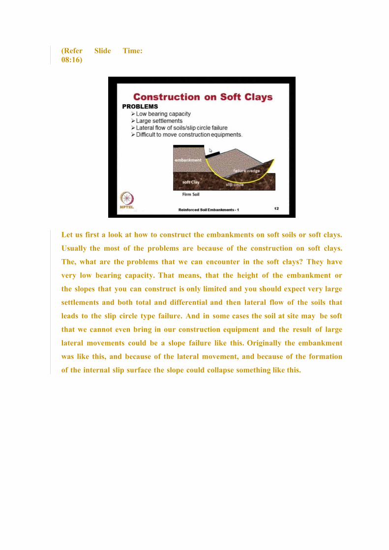
Let us first a look at how to construct the embankments on soft soils or soft clays.
Usually the most of the problems are because of the construction on soft clays.
The, what are the problems that we can encounter in the soft clays? They have
very low bearing capacity. That means, that the height of the embankment or
the slopes that you can construct is only limited and you should expect very large
settlements and both total and differential and then lateral flow of the soils that
leads to the slip circle type failure. And in some cases the soil at site may be soft
that we cannot even bring in our construction equipment and the result of large
lateral movements could be a slope failure like this. Originally the embankment
was like this, and because of the lateral movement, and because of the formation
of the internal slip surface the slope could collapse something like this.

(Refer Slide Time:09:26)
What are the different alternatives for construction in the soft clays? The, if the
thickness of the soft clays not very much, the easiest solution is replace the soil
with a good quality soil. We just simply remove all this soft clay and then
replace it with some good granular soil or we can use a chemical or thermal
treatment of the foundation soil so that we can increase the strength. That is the
one simple form is, just simply pumping in the concrete the cement grout, deep
mixing and jet grouting, and then basal reinforcement or the basal mattress or
sometimes a planar reinforcement may not be sufficient because of the height of
the embankment. In such cases, we can provide a three dimensional type of
mattress that could be filled with stone aggregates or some other very strong
materials so that we form a semi rigid mat.
Or we can use pre-consolidation with pre-fabricated vertical drains or through
the vacuum consolidation or we can use our traditional stone columns or the
encased stone columns. We can have piles with a reinforced concrete slab which is
by far the most expensive one, because we know that concrete is much more
expensive than using just soil alone or we can going for piles with geosynthetic
reinforced platform. These are called as piled embankments and of late this, the
last alternative has become very popular because we do not need to wait for the
pre- consolidation to be completed, we can go in and do the construction as the
ground is being treated, this we will see in some other lecture.

(Refer Slide Time:11:28)
And what are the shear strength properties that we can use for design of slopes.
The, we should realize even before we design that these slopes especially those
resting on soft soils, we should expect that they will undergo very large
deformations and because of that we prefer to use or it is recommended in the
design codes that we should use the shear strength properties corresponding to
the constant volume state or the constant volume strength parameters, and
these happen at very large deformations and the embankments are the slopes
that are built on very strong soils, we can use the peak friction angle pi, the
peak shear strength parameters.
(Refer Slide Time:12:27)
Well just as we had very large number load factors to consider, in
the case of retaining walls even for the embankments, we have a
table that is given by the BS 8006 code to, that gives different
material factors. For example, the load factors to consider for two
different cases, one is the ultimate limit state and the other is the
serviceability limit state. The load factor of 1.3 is recommended for
the embankment fill then other dead loads and live load the point
loads the load factor of 1.2 is given then for the live loads slightly
higher 1.3 and the serviceability limit state as we have seen earlier
that relates to the to the regular service condition. So, all these
factors are one and then the soil material factors especially when we
use the Φcv because its already factored, factoring in lot of
parameters like the loss of strength and then other parameters, we
do not apply any other additional parameter on the Φcv.
So, this factor is just simply one. But then, if you are using any c prime for effective
stress analysis, we use a very high factor of safety or the reduction factor 1.6, and
if it is an un-drained cohesive strength corresponding to large strains we use a
factor of one and even on the reinforcement strength, we apply a lot of factors and
this should be consistent with the type of reinforcement under the design life and
so on. And the factors of safety that we aim for sliding is 1.3, and against pull-
out is 1.3. It is actually, if we combine this factor 1.3 against this live load and
then the field factor of 1.3, if you combine both of them it works out 1.3 times 1.3
that is one nearly 1.7. So, that is the, that corresponds to the factor of safety of 1.7
in the working stress design methods.
(Refer Slide Time:15:00)


Well, in the case of very weak foundation soils, we go for ground
improvement so that we can improve this soil properties to some
reasonable level where in we can have economical solutions.
Otherwise the treatment could be so expensive the construction
could be so expensive. So, the requirement of very large amount of
reinforcement, the plane the, in the form of geogrids or the geocells,
and so on.
(Refer Slide Time:15:33)
Some of these ground improvement methods are, very briefly, stone column is one
method, there are different types, the rammed stone columns, and the vibroflot
stone columns, that can be formed either by soil displacement or by soil
replacement. This also, we will see a bit later on in some other lecture.

(Refer Slide Time:15:57)
Here we see an example of an encased stone column, wherein we have a
granular column, but that is placed inside a tube of geotextile or geogrid so that
a combination of this granular material that is encased within the geosynthetic
behaves like a very strong and stiff column. This, we will see in the some other
lecture and the particular photograph that you have seen, this is the ground
treatment that was given to the A 380 factory in Hamburg, Germany.
(Refer Slide Time:16:33)

And another popular method that is traditionally used for ground
improvement is the pre-consolidation or we call it as accelerated
consolidation and in the early days when this technique came into
being people used the sand drains or the sand columns, wherein we
drill a hole, a borehole and then fill it with highly permeable material
like sand or some aggregate. But with advent of geosynthetics, we
started using pre-fabricated vertical drains or PVDs and the
principle that is used in accelerated consolidation is, we reduce the
drainage path length, because we know that the time for
consolidation t is related to the T v that is the time factor that is
related to degree of consolidation and then the square of the drainage
path length divided by C v, in this case, in the equation the C v is a
constant and the T v is also a constant, because it is related to the
degree of consolidation say for example, if you want 90 percent
consolidation the T v we can get from the charts corresponding to the
90 percent consolidation.
And the only quantity that is variable is the drainage path length d, and if we do
not have any sand drains, the water particle has to travel this much length to
escape from the ground. Whereas, if we install these sand columns, the maximum
length that a water particle has to travel is only this much very small length, and
because of that the time for consolidation reduces drastically, because the time is
directly proportional to d square.
(Refer Slide Time:18:33)

And here is a schematic of the pre-fabricated vertical drain, it consists of a
inner core, and then an outer textile that acts like a filter.
(Refer Slide Time:18:47)
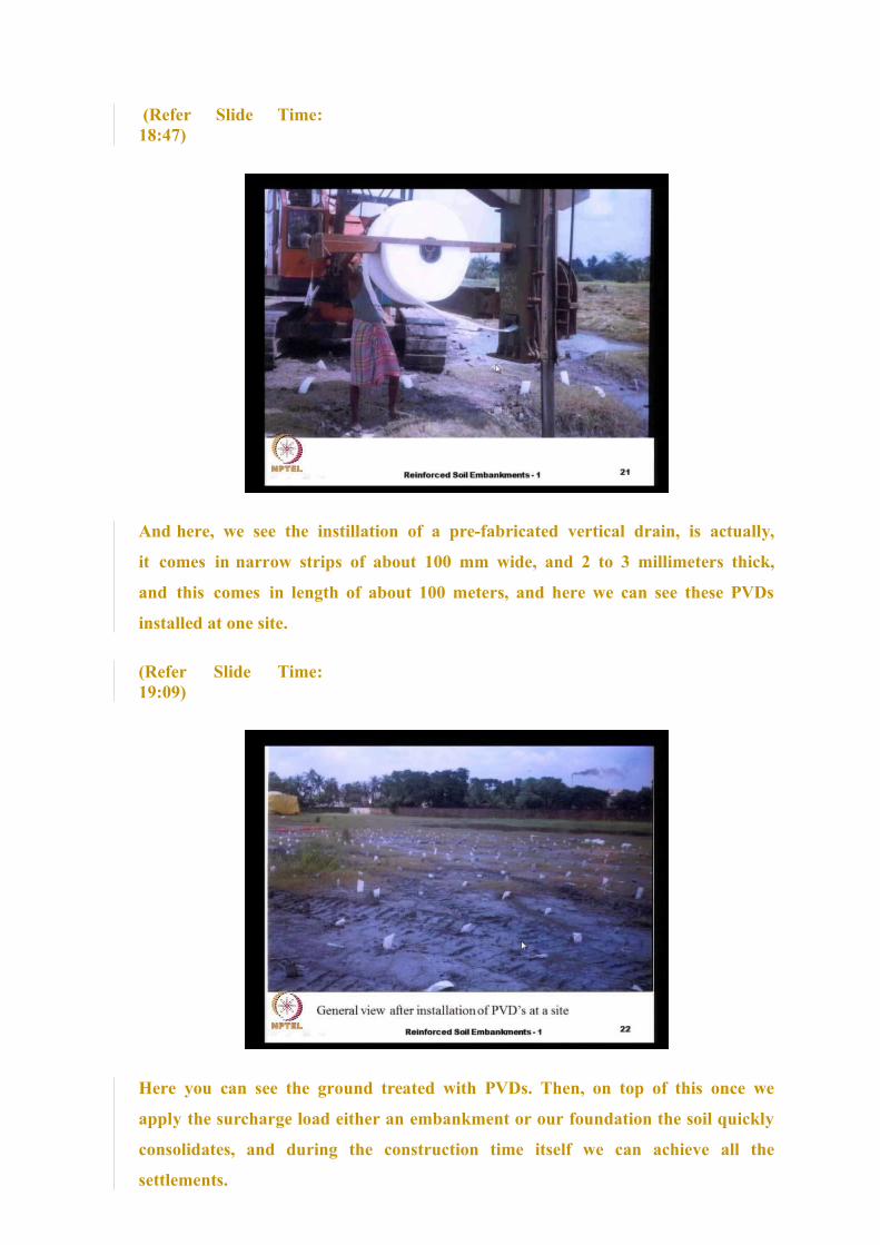
And here, we see the instillation of a pre-fabricated vertical drain, is actually,
it comes in narrow strips of about 100 mm wide, and 2 to 3 millimeters thick,
and this comes in length of about 100 meters, and here we can see these PVDs
installed at one site.
(Refer Slide Time:19:09)
Here you can see the ground treated with PVDs. Then, on top of this once we
apply the surcharge load either an embankment or our foundation the soil quickly
consolidates, and during the construction time itself we can achieve all the
settlements.

(Refer Slide Time:19:29)
The other popular method is the geosynthetic pile raft, is actually the pile raft is
a very common foundation engineering treatment that we give for transferring
heavy loads into soils with a highly variable strata or where the expected
settlements are large. Here the, instead of the raft, what we do is we use a
geosynthetic reinforcement either a geocell or a planar reinforcement to form a
relatively stiff mat and we use a small piles with a pile cap. And invariably the
piles that we use in the geosynthetic pile raft they are plane concrete elements,
they do not have any steel reinforcements mainly because, there is no bending.
Here our slab that we construct does not have any bending stiffness. Because it is
all made up of flexible materials and then the design itself is based on the arching
theories, that we will see later on and this concept of the geosynthetic pile raft
system has successfully been used at several places and it is found to be very fast
and also very economical compared to so many other alternatives.
(Refer Slide Time:21:03)
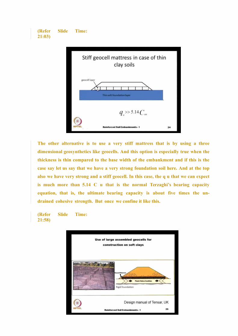
The other alternative is to use a very stiff mattress that is by using a three
dimensional geosynthetics like geocells. And this option is especially true when the
thickness is thin compared to the base width of the embankment and if this is the
case say let us say that we have a very strong foundation soil here. And at the top
also we have very strong and a stiff geocell. In this case, the q u that we can expect
is much more than 5.14 C u that is the normal Terzaghi’s bearing capacity
equation, that is, the ultimate bearing capacity is about five times the un-
drained cohesive strength. But once we confine it like this.
(Refer Slide Time:21:58)

It is actually, here is a schematic on how the bearing capacity
increases. Because of the squeezing of the soil between two solid and
rigid under rough plates one surface made up of the geocell and the
other surface made up of the rigid foundation we have the slip
surfaces formed like this and because of this our bearing capacity
factor increases to almost 15 to 16. And here on the left hand side,
you see an example of open geocell mattress being fabricated at the
site, which will be later filled with stones or boulders or aggregates
to form this stiff geocell mattress, this also, the design and
construction aspects we will see in some other lecture.
(Refer Slide Time:22:55)
Another very popular method is the use of vacuum pressure for accelerated
consolidation. Here, what we do is we seal the soil to be treated completely by
using geomembranes or some other techniques by digging in trenches and filling
with some bentonite and polymer mixed bentonite slurry and so that the entire
volume of soil that is to be treated is sealed. And we apply vacuum and once we
apply the vacuum, the atmospheric pressure that is actually, basically we are
removing the atmospheric pressure from inside. This volume of soil that needs
to be treated and the atmospheric pressure starts acting. And the main
advantage here is, we achieve the increase in the effective stress to drive our
consolidation without any increase in the total stress.

That means that we do not need to bring in the soil, and dump it at the place to
achieve the consolidation. And then the increase in the effective stress is constant
with depth. That is the major difference between this method of treatment, and the
other methods. Because in the normal, in the conventional surcharge method we
need to bring in the soil and put it in and because of that the stresses that are
generated they are anisotropic. The stress is more the vertical direction compared
to the lateral directions and because of that we generate shear stresses, whereas
here the vacuum being an isotropic stress there is no generation of shear
stresses. And o n the right hand side bottom, you see a small example of
laboratory test being performed to achieve the vacuum consolidation.
(Refer Slide Time:25:02)
And now let us come back to the design of a basal reinforcement. And in many
cases, the basal reinforcement is also used as a construction expedient because
i n some places the soil may be so soft that we cannot even bring in our
construction equipment for doing the minimal construction work. In such cases,
what we do is, we provide a very strong and stiff basal reinforcement along with
a sufficiently thick granular soil so that we can freely bring in our construction
equipment and start the construction process and we can also provide it to increase
the factor of safety of the embankment.
(Refer Slide Time:25:56)
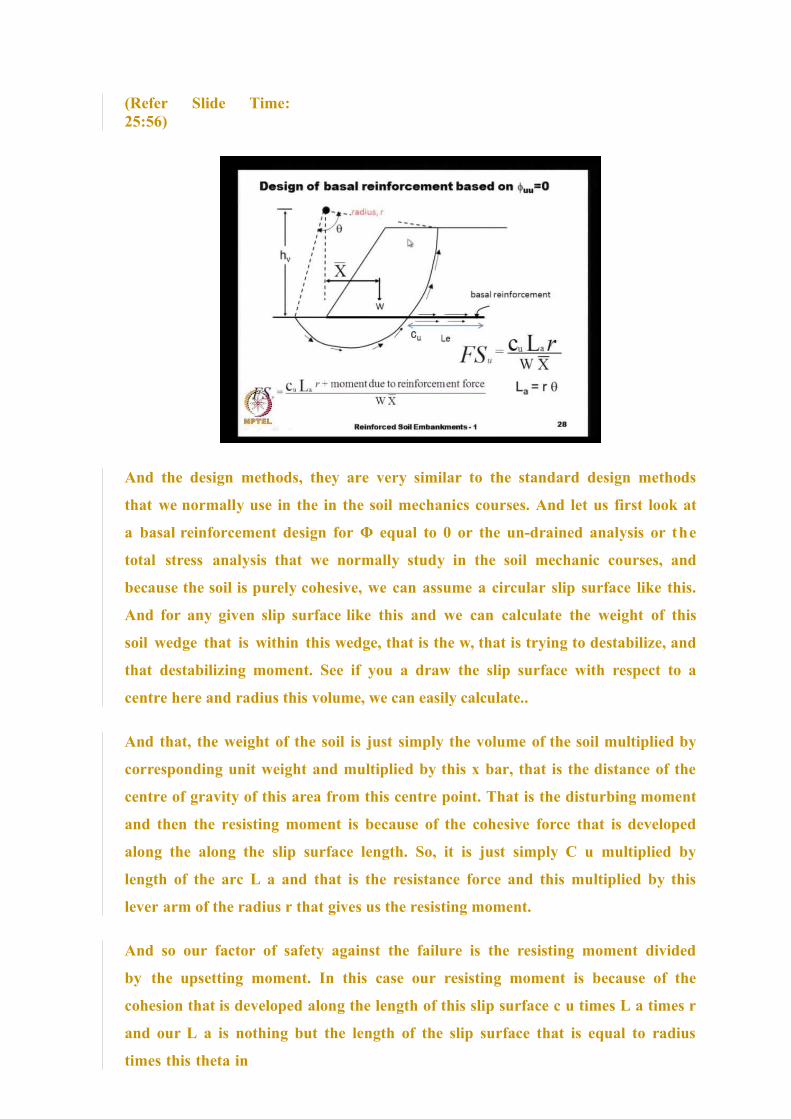
And the design methods, they are very similar to the standard design methods
that we normally use in the in the soil mechanics courses. And let us first look at
a basal reinforcement design for Φ equal to 0 or the un-drained analysis or the
total stress analysis that we normally study in the soil mechanic courses, and
because the soil is purely cohesive, we can assume a circular slip surface like this.
And for any given slip surface like this and we can calculate the weight of this
soil wedge that is within this wedge, that is the w, that is trying to destabilize, and
that destabilizing moment. See if you a draw the slip surface with respect to a
centre here and radius this volume, we can easily calculate..
And that, the weight of the soil is just simply the volume of the soil multiplied by
corresponding unit weight and multiplied by this x bar, that is the distance of the
centre of gravity of this area from this centre point. That is the disturbing moment
and then the resisting moment is because of the cohesive force that is developed
along the along the slip surface length. So, it is just simply C u multiplied by
length of the arc L a and that is the resistance force and this multiplied by this
lever arm of the radius r that gives us the resisting moment.
And so our factor of safety against the failure is the resisting moment divided
by the upsetting moment. In this case our resisting moment is because of the
cohesion that is developed along the length of this slip surface c u times L a times r
and our L a is nothing but the length of the slip surface that is equal to radius
times this theta in

radians. And suppose, this factor of safety is not adequate for our construction
purposes we can add in some basal reinforcement and that can increase our
factor of safety. And the typical factors of safety that we aim for are about 1.3
to 1.5 depending on the importance of the structure that are building. And
after providing this basal reinforcement, the factor of safety increases, because
of this additional movement the stabilizing moment that we get and the
additional stabilizing moment is added on to the stabilizing moment, because of
the soil resistance that entire quantity divided by w times x bar is our factor of
safety of the reinforced slope. And invariably as we know the slope stability
analysis is very tedious process, we need to consider different slip circle centre
points and then the radius so that we identify the most critical slip circle and it
is not necessary that the critical slip circle for the unreinforced soil is the same
as that for the case with basal reinforcement and. So, we tend to use some
computer programs that can automatically do all these design calculations.
And there are two cases that we can consider because sometimes the basal
reinforcement could be provided in the form of steel strips or welded wire meshes
and in such cases where the reinforcement is very stiff, we can assume that the
reinforcement remains horizontal.
(Refer Slide Time:30:26)
Whereas, if you provide a flexible type reinforcement like the geosynthetic or a
geotextile it is possible that at the point of on the contact with the slip surface,
there will be
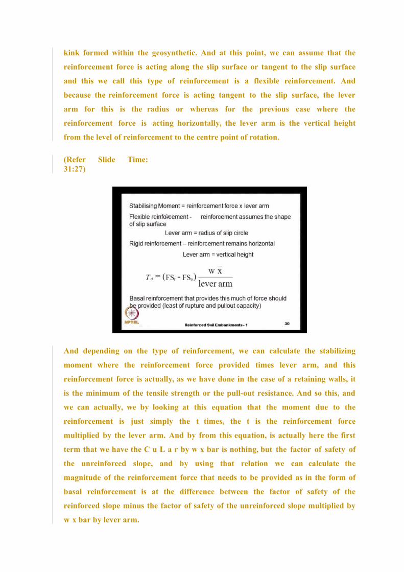
kink formed within the geosynthetic. And at this point, we can assume that the
reinforcement force is acting along the slip surface or tangent to the slip surface
and this we call this type of reinforcement is a flexible reinforcement. And
because the reinforcement force is acting tangent to the slip surface, the lever
arm for this is the radius or whereas for the previous case where the
reinforcement force is acting horizontally, the lever arm is the vertical height
from the level of reinforcement to the centre point of rotation.
(Refer Slide Time:31:27)
And depending on the type of reinforcement, we can calculate the stabilizing
moment where the reinforcement force provided times lever arm, and this
reinforcement force is actually, as we have done in the case of a retaining walls, it
is the minimum of the tensile strength or the pull-out resistance. And so this, and
we can actually, we by looking at this equation that the moment due to the
reinforcement is just simply the t times, the t is the reinforcement force
multiplied by the lever arm. And by from this equation, is actually here the first
term that we have the C u L a r by w x bar is nothing, but the factor of safety of
the unreinforced slope, and by using that relation we can calculate the
magnitude of the reinforcement force that needs to be provided as in the form of
basal reinforcement is at the difference between the factor of safety of the
reinforced slope minus the factor of safety of the unreinforced slope multiplied by
w x bar by lever arm.

And so, we should provide this much of basal reinforcement that develops this
much of force, and sometimes we may not be able to provide it in one single
layer, we may provide multiple layers say some two or three layers to increase
the, to provide sufficient force. And as I mentioned before, the reinforcement force
that we consider is the lower of either the tensile strength or the pull-out resistance.
(Refer Slide Time:33:28)
And when we do these calculations, we should also consider the case of the sliding
of the entire reinforcement mass or the entire soil mass like this. Say, let us say
that we have built a built a slope with some basal reinforcement based on our slip
circle design. And we should also make sure that the extreme case where in the
lateral forces that are acting inside the embankment should not push out the
entire slope like this. And the length that we have, it should be sufficient to resist
the lateral sliding, because of this, the different forces the triangular distribution
of forces, because the self-weight and this rectangular distribution of forces
because of the uniform surcharge. And in these calculations, we see that the
shear resistance is developed only on one side, on one surface. And this lateral
force P that is trying to push our slope away from the rest of the soil mass is one
half Ka Ɣ H2 plus K a times q H, which is the same as earlier except that the K a
here is different because our the Rankine’s Ka is applicable for vertical retaining
walls.

But here our slope is not vertical, but it is inclined at an angle of beta, and our K
a is given as sin of beta minus Φ by square root of sin beta plus sin Φ times square
root of sin beta, the entire thing to the square and if you substitute a beta of 90
degrees that is corresponding to vertical retaining wall, this comes to 1 minus sin
Φ by 1 plus sin Φ and invariably when beta is less than 90 degrees this Ka is much
less than what we had earlier.
(Refer Slide Time:35:51)
And we should also consider the possibility of the provided reinforcement, pulling
out of the soil and let us say that the length of reinforcement beyond this position
is L e. And we should make sure that this length L e is sufficient to generate the
pull-out resistance against this lateral force with some sufficient factor of
safety. And even in the earlier case, when we do this slip circle analysis, the
length of the reinforcement that is generating the pull-out resistance is only
the length of this reinforcement beyond the rupture surface. And the quantity of
reinforcement is not only a function of the rotational stability, but also a function
of the lateral sliding forces and pull-out forces.

(Refer Slide Time:37:05)
Previous analysis is only valid for Φ equal to 0 type of soils or un-drained
behaviour of the clays. But sometimes the soil may have both cohesion and a
friction angle and in that case our strength varies with depth of the soil. And we
can use our conventional slices method and this is the ordinary method of slices or
the Fellenius method or we can also use the Bishop’s method of slices, where in we
do not consider the entire soil surface as one single mass, but we divide this into
certain number of slices usually at least about 6 to 10. And the more number of
slices we have the more accurate is our result and we look at the equilibrium of
each of these slices like this.
Let us say that W i is the weight of the soil within this slice i’th slice, and because of
this there is a normal force N. And then a tangential force T that is the sliding
force, and N is nothing but W i times cosine αi where αi is the is the inclination of
this base of the i’th slope i’th slice. And the T i is W i times sin αi. And for a
general case where we have pore water there could be some pore pressure u
because of the seepage or some other factors and so we can write our factor of
safety against slip circle failure in the same manner like earlier by taking moments
about this point the c prime that is the affective cohesive strength multiplied by the
L a that is the length of the slip surface.
That is the R times theta times r that is radius of the slip circle plus the moment
that is generated because of this resistance by this N the normal force that is tan
Φ times W i cosine α; that is the normal force minus u i that is the pore
pressure
multiplied the base length L i, that is our resistance force, and that multiplied by
R the radius will give us the resistance force. And then together with this, we add
some the resistance that we get, because of this reinforcement layers, and if we
provide multiple layers, we do a summation.
the, T multiplied by either the vertical height Y i or the radius depending on the
type of reinforcement that we provide either rigid reinforcement or a flexible
reinforcement, this entire thing divided by the by the upsetting moment that is the
W i sin α i multiplied by R. And so, this the, this will give us the factor of safety
of the of the reinforced slope and as I mentioned earlier the target factor of safety
is about 1.3 to 1.5. And we need to do some trial and error analysis and find out
the quantity of reinforcement that we need to provide. Here, the analysis is trial
and error because the resisting moment also depends on where you place the
reinforcement. If you place the reinforcement at a slightly lower depth than the
base of this embankment, you get a higher resisting moment.
(Refer Slide Time:41:26)
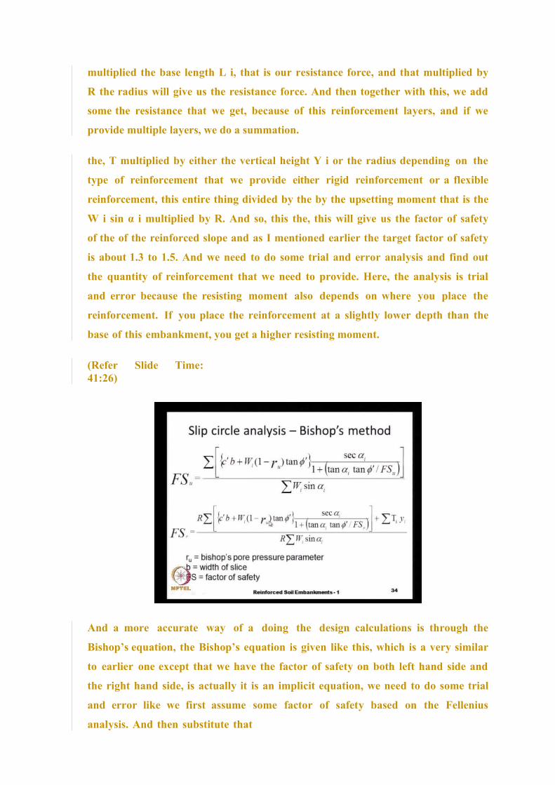
And a more accurate way of a doing the design calculations is through the
Bishop’s equation, the Bishop’s equation is given like this, which is a very similar
to earlier one except that we have the factor of safety on both left hand side and
the right hand side, is actually it is an implicit equation, we need to do some trial
and error like we first assume some factor of safety based on the Fellenius
analysis. And then substitute that

on the right hand side and the factor of safety that we get from the first
analysis is once again substituted back and we do this trails until both left hand
side and the right hand side are equal, whatever is assumed is equal to the to the
calculated value.
And here all these parameters are the same as earlier except our b is the
horizontal width of the slice and r u is the is the pore pressure parameter Bishop’s
pore pressure parameter, typically this is about it depends on the type of soil and
then the type of a drainage conditions and so on. It could be anywhere from 0 to
about 0.4 to 0.5, and our F S is the factor of safety F S u is the factor of safety of
the unreinforced slope, and then F S r is the factor of safety of the reinforced
slope and by using these equations, we can come out with the quantity of
reinforcement, and all these calculations, they are done by using some computer
programs.
(Refer Slide Time:43:12)
And here you see an example of a computer program result, and this computer
program, you will get it as part of this course, and here you see the factor of
safety of an unreinforced slope, and with some tension crack especially when
you have a clay soil, we should expect in the formation of tension crack, the
tension crack height, we know that this height is a 2 C by Ɣ square root of Ka,
and in this particular case the factor of safety is only 0.66. So, we need to bring it
up to say about 1.3 or 1.4 by doing some trials and by putting in some
reinforcement of different strengths or different
locations. So, we will s ee some numerical examples to illustrate these
procedures a bit later on.
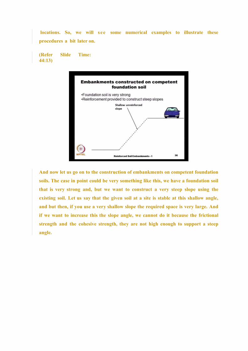
(Refer Slide Time:44:13)
And now let us go on to the construction of embankments on competent foundation
soils. The case in point could be very something like this, we have a foundation soil
that is very strong and, but we want to construct a very steep slope using the
existing soil. Let us say that the given soil at a site is stable at this shallow angle,
and but then, if you use a very shallow slope the required space is very large. And
if we want to increase this the slope angle, we cannot do it because the frictional
strength and the cohesive strength, they are not high enough to support a steep
angle.
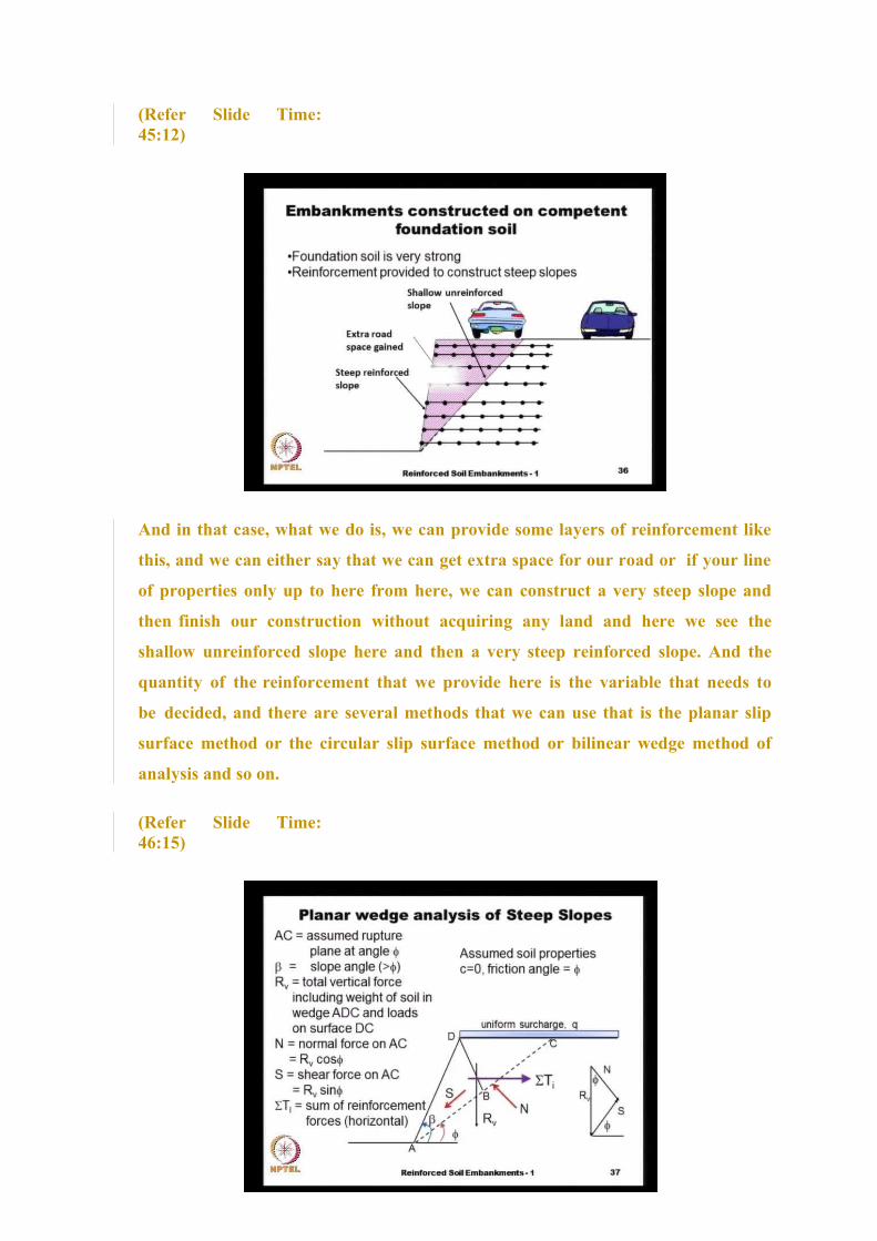
(Refer Slide Time:45:12)
And in that case, what we do is, we can provide some layers of reinforcement like
this, and we can either say that we can get extra space for our road or if your line
of properties only up to here from here, we can construct a very steep slope and
then finish our construction without acquiring any land and here we see the
shallow unreinforced slope here and then a very steep reinforced slope. And the
quantity of the reinforcement that we provide here is the variable that needs to
be decided, and there are several methods that we can use that is the planar slip
surface method or the circular slip surface method or bilinear wedge method of
analysis and so on.
(Refer Slide Time:46:15)

And that, I think we will take up in
some other lecture.
Thank you very much.