geol 600 notable historical earthquakes source mechanisms and body wave radiation patterns...
Post on 21-Dec-2015
213 views
TRANSCRIPT

Geol 600 Notable Historical Earthquakes
Source mechanisms and body wave radiation patterns
http://www-rohan.sdsu.edu/~kbolsen/geol600_nhe_mechanism.ppt
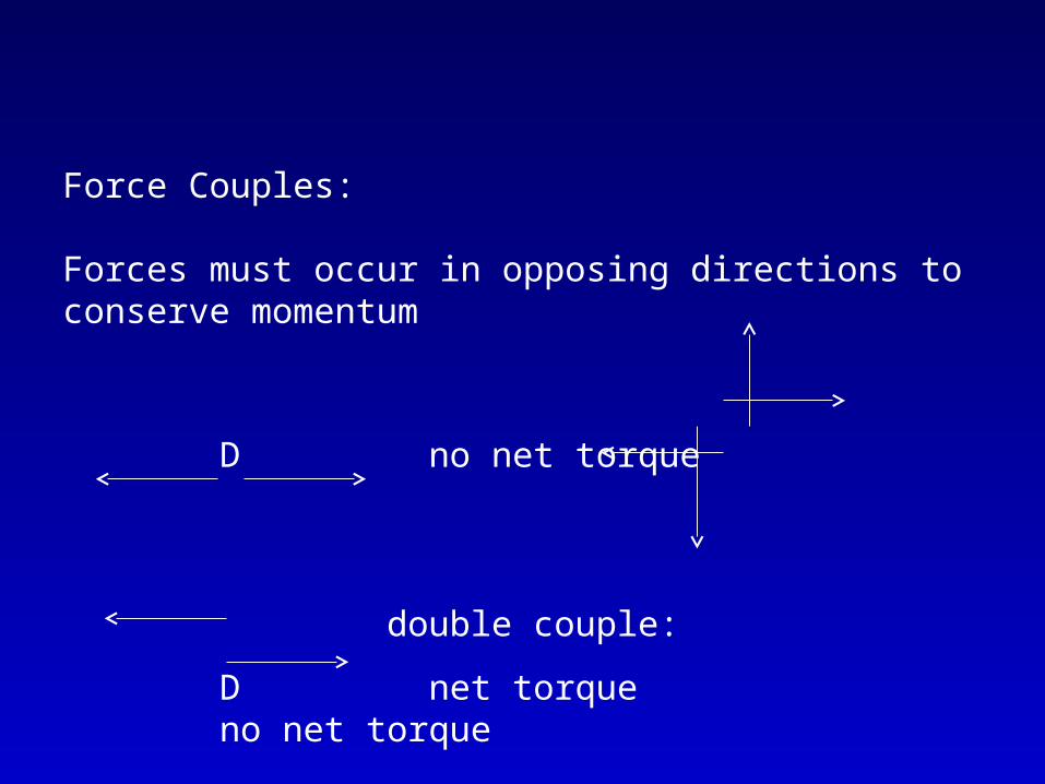
Force Couples:
Forces must occur in opposing directions to conserve momentum
D no net torque
double couple:
D net torque no net torque
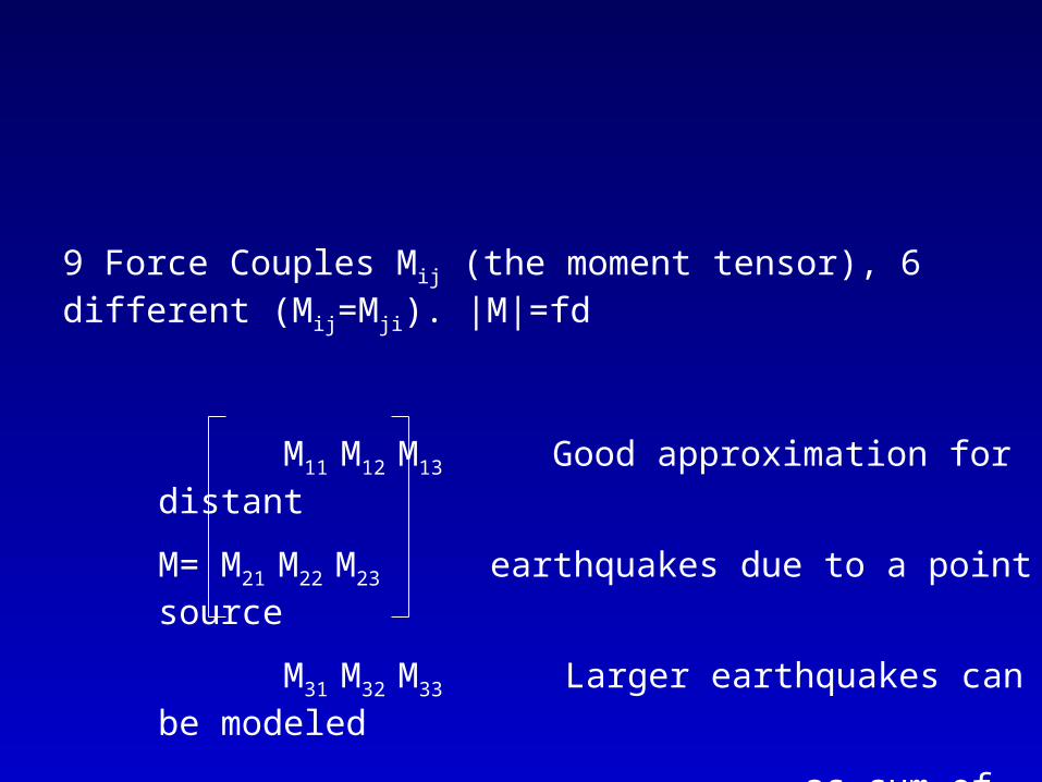
9 Force Couples Mij (the moment tensor), 6 different (Mij=Mji). |M|=fd
M11 M12 M13 Good approximation for distant
M= M21 M22 M23 earthquakes due to a point source
M31 M32 M33 Larger earthquakes can be modeled
as sum of point sources

Because of ambiguity Mij=Mji two fault planes are consistent with a double-couple model: the primary fault plane, and the auxillary fault plane (model for both generates same far-field displacements).
Distinguishing between the two requires further (geological) information
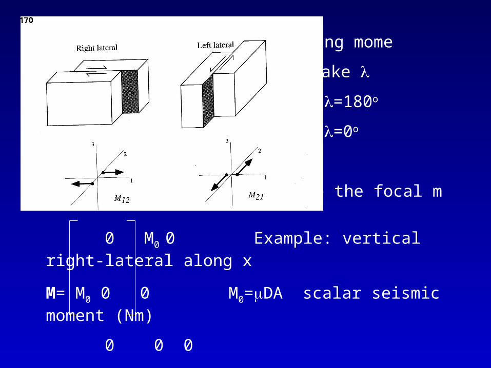
Description of earthquakes using mome
Parameters: strike , dip , rake
Vertical fault, right-lateral =180o
Vertical fault, right-lateral =0o
Strike, dip, rake, slip define the focal m
0 M0 0 Example: vertical right-lateral along x
M= M0 0 0 M0=DA scalar seismic moment (Nm)
0 0 0
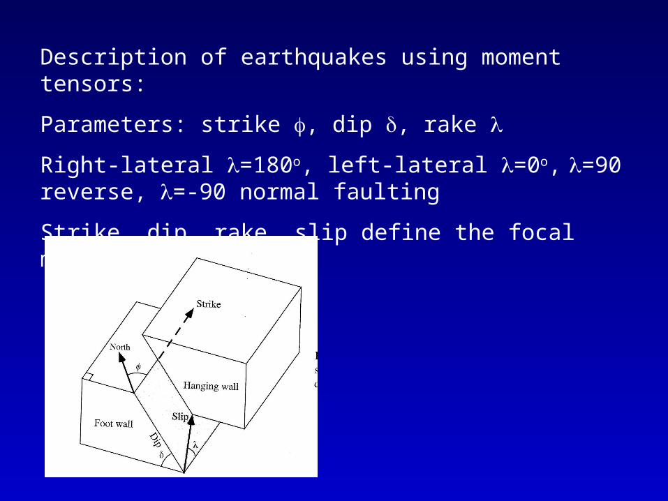
Description of earthquakes using moment tensors:
Parameters: strike , dip , rake
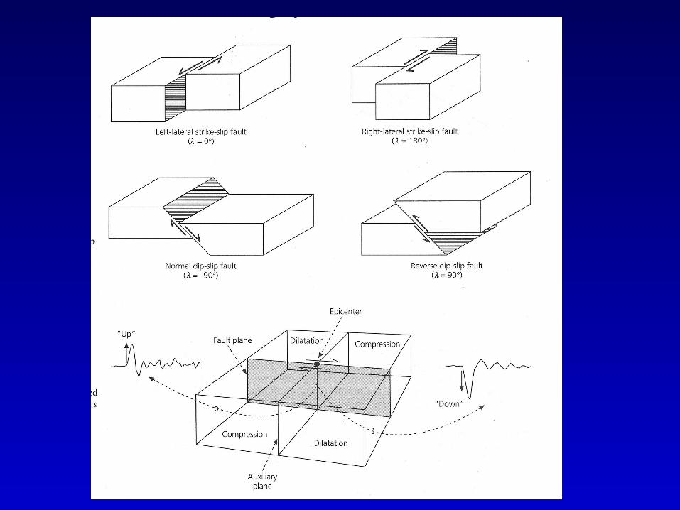
Right-lateral =180o, left-lateral =0o, =90 reverse, =-90 normal faulting
Strike, dip, rake, slip define the focal mechanism
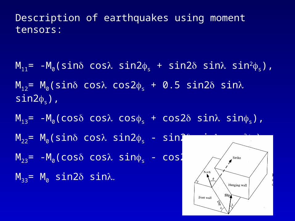
Description of earthquakes using moment tensors:
M11= -M0(sin cos sin2s + sin2 sin sin2s),
M12= M0(sin cos cos2s + 0.5 sin2 sin sin2s),
M13= -M0(cos cos coss + cos2 sin sins),
M22= M0(sin cos sin2s - sin2 sin cos2s),
M23= -M0(cos cos sins - cos2 sin coss),
M33= M0 sin2 sin


Determining an earthquake’s mechanism from first P motions
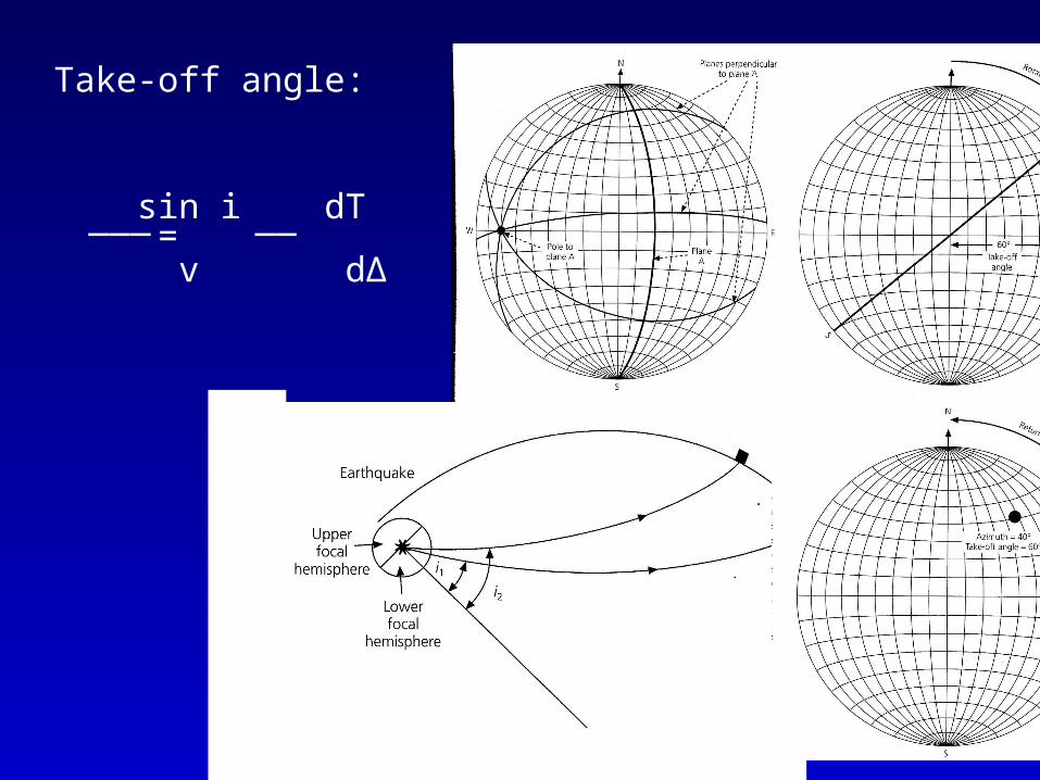
Take-off angle:
sin i dT
v d∆
___ __=
QuickTime™ and aTIFF (Uncompressed) decompressor
are needed to see this picture.
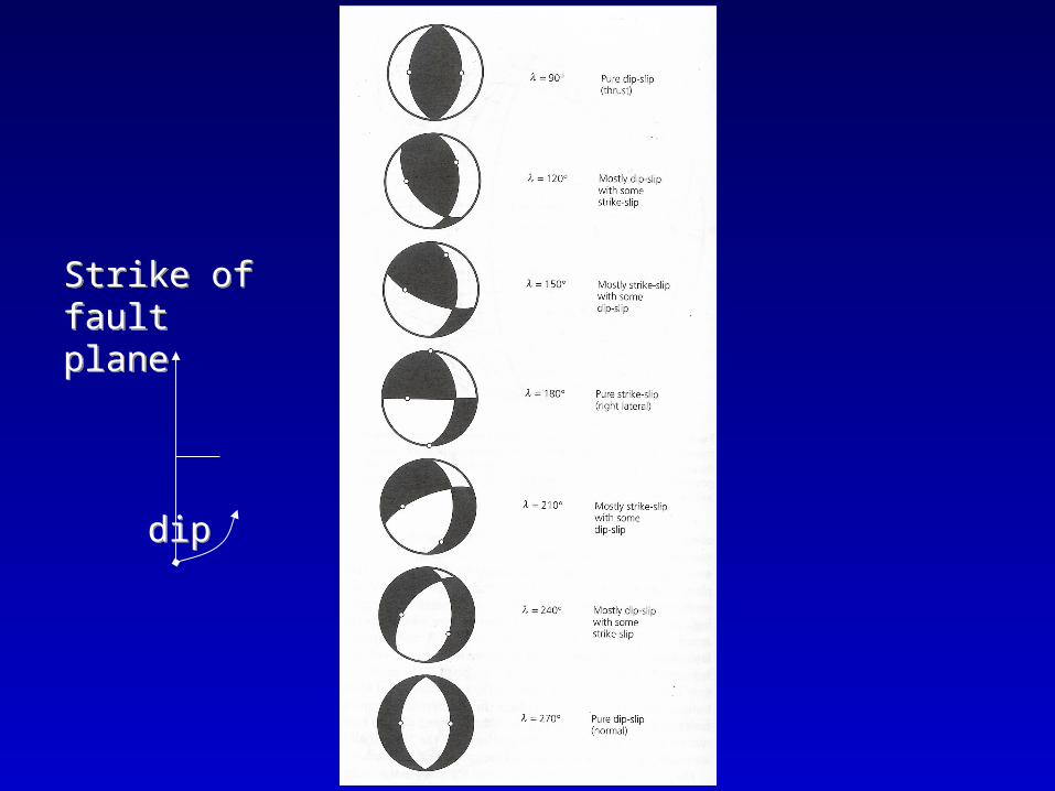
Strike of fault plane
dip
Strike of fault plane
dip
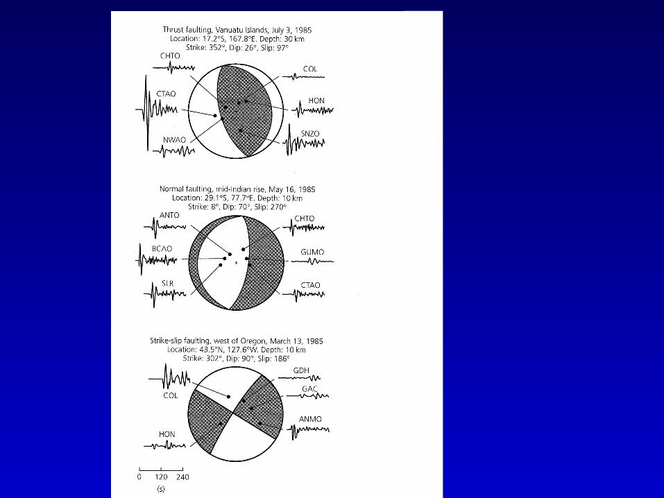

Earthquake focal mechanism determination from first P motion (assuming double-couple model):
• Only vertical component instruments needed
• No amplitude calibration needed
• Initial P motion easily determined (up or down)
• Up: ray left the source in compressional quadrant
• Down: ray left source in dilatational quadrant
• Plotted on focal sphere (lower hemisphere)
• Allows division of focal sphere into compressional/dilatational quadrants
• Focal mechanism is then found from two orthogonal planes (projections on the focal sphere)

Earthquake focal mechanism determination from first P motion (assuming double-couple model):
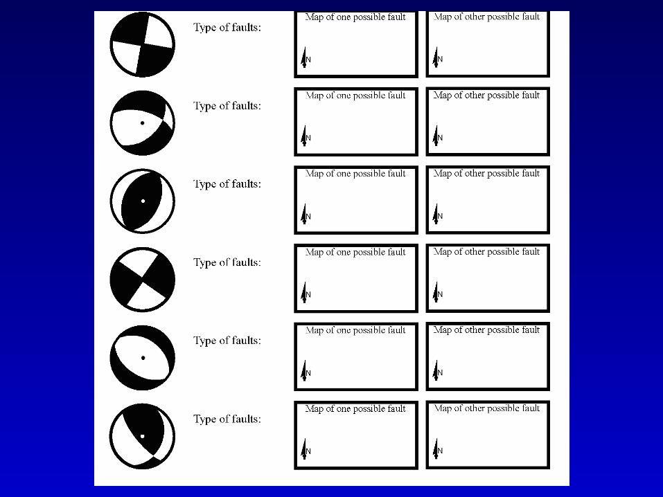
• Focal sphere is shaded in compressional quadrants, generating ‘beach ball’
• Tension axis in the middle of shaded region
• Pressure axis in the middle of unshaded region
• Only represents stress tensor if slip on plane of max shear
• Normal faulting: white with black edges
• Reverse faulting: black with white edges
• Strike-slip: cross pattern