generalized information architecture for managing ... · ibm’s rational doors (dynamic object...
TRANSCRIPT
SANDIA REPORTSAND2014-20563Unlimited ReleasePrinted Month and Year
Generalized Information Architecture for Managing Requirements in IBM’s Rational DOORS® Application
Kathryn Mary AragonShelley Margit EatonMarjorie Turner McCornackSharon Anne Shannon
Prepared bySandia National LaboratoriesAlbuquerque, New Mexico 87185 and Livermore, California 94550
Sandia National Laboratories is a multi-program laboratory managed and operated by Sandia Corporation, a wholly owned subsidiary of Lockheed Martin Corporation, for the U.S. Department of Energy's National Nuclear Security Administration under contract DE-AC04-94AL85000.
Approved for public release; further dissemination unlimited.
Version 1.0 2 November 2014
Issued by Sandia National Laboratories, operated for the United States Department of Energy by Sandia Corporation.
NOTICE: This report was prepared as an account of work sponsored by an agency of the United States Government. Neither the United States Government, nor any agency thereof, nor any of their employees, nor any of their contractors, subcontractors, or their employees, make any warranty, express or implied, or assume any legal liability or responsibility for the accuracy, completeness, or usefulness of any information, apparatus, product, or process disclosed, or represent that its use would not infringe privately owned rights. Reference herein to any specific commercial product, process, or service by trade name, trademark, manufacturer, or otherwise, does not necessarily constitute or imply its endorsement, recommendation, or favoring by the United States Government, any agency thereof, or any of their contractors or subcontractors. The views and opinions expressed herein do not necessarily state or reflect those of the United States Government, any agency thereof, or any of their contractors.
Printed in the United States of America. This report has been reproduced directly from the best available copy.
Available to DOE and DOE contractors fromU.S. Department of EnergyOffice of Scientific and Technical InformationP.O. Box 62Oak Ridge, TN 37831
Telephone: (865) 576-8401Facsimile: (865) 576-5728E-Mail: [email protected] ordering: http://www.osti.gov/bridge
Available to the public fromU.S. Department of CommerceNational Technical Information Service5285 Port Royal Rd.Springfield, VA 22161
Telephone: (800) 553-6847Facsimile: (703) 605-6900E-Mail: [email protected] order: http://www.ntis.gov/help/ordermethods.asp?loc=7-4-0#online
Version 1.0 3 November 2014
SAND2014-20563Unlimited Release
Printed Month Year
Generalized Information Architecture for Managing Requirements in IBM’s Rational
DOORS® Application
Kathryn Mary AragonShelley Margit Eaton
Marjorie Turner McCornackSharon Anne Shannon
High Confidence System Environments, Org. 6923Sandia National Laboratories
P.O. Box 5800Albuquerque, New Mexico 87185-MS1138
Abstract
When a requirements engineering effort fails to meet expectations, often times the requirements management tool is blamed. Working with numerous project teams at Sandia National Laboratories over the last fifteen years has shown us that the tool is rarely the culprit; usually it is the lack of a viable information architecture with well-designed processes to support requirements engineering. This document illustrates design concepts with rationale, as well as a proven information architecture to structure and manage information in support of requirements engineering activities for any size or type of project. This generalized information architecture is specific to IBM’s Rational DOORS (Dynamic Object Oriented Requirements System) software application, which is the requirements management tool in Sandia’s CEE (Common Engineering Environment). This generalized information architecture can be used as presented or as a foundation for designing a tailored information architecture for project-specific needs. It may also be tailored for another software tool.

Version 1.0 4 November 2014
Version 1.0 5 November 2014
CONTENTS
1. Introduction.................................................................................................................................91.1. Document Scope..............................................................................................................91.2. ReqMAPS Team..............................................................................................................91.3. Benefits of Using a Generalized Information Architecture ...........................................10
2. Information Architecture Definition.........................................................................................112.1. Project and Folder Structure ..........................................................................................112.2. Requirement Trace Model .............................................................................................16
2.2.1. Modules ...........................................................................................................162.2.2. Linking.............................................................................................................162.2.3. Retrofitting Documents into DOORS Linking Model.....................................192.2.4. Folder, Module, and Linking Models ..............................................................202.2.5. Linking with DOORS Tables ..........................................................................23
2.3. Access Control and Permissions....................................................................................232.3.1. Designing the Security Model .........................................................................232.3.2. Security Model Rules and Assumptions..........................................................262.3.3. Sandia Metagroups ..........................................................................................262.4.4. DOORS Group for External Users ..................................................................272.3.5. Logical Metagroups on SCN ...........................................................................272.4.6. Metagroup Naming Standards .........................................................................28
2.4. Options for Relating Information in DOORS................................................................292.5. Custom Attributes and Types for Requirements ...........................................................312.6. Custom Views for Requirements...................................................................................342.7. Reporting and Exporting Data .......................................................................................36
2.7.1. Reporting Options............................................................................................362.7.2. Report Formatting and Information Architecture............................................37
3. Key Information Architectural Concepts..................................................................................393.1. Defining the DOORS Requirements Management Project ...........................................39
3.1.1. DOORS Project Roles and Responsibilities ....................................................393.1.2. Centralized versus Decentralized Approaches ................................................393.1.3. Requirements Management Project Scope ......................................................403.1.4. Tool Functionality ...........................................................................................413.1.5. Integration with Data in Other Tools...............................................................413.1.6. Resources to Support the Project Scope ..........................................................41
3.2 Interacting with the DOORS Data .................................................................................423.2.1. Creating Requirements ....................................................................................423.2.2. Updating, Viewing, and Linking Requirements ..............................................443.2.3. Reporting .........................................................................................................44
3.3. Modeling the DOORS Information ...............................................................................463.3.1 Information Architecture Concepts .................................................................463.3.2 Module Architecture Approaches....................................................................473.3.3. SCN vs. SRN DOORS.....................................................................................483.3.4. Describing and Viewing Data Content ............................................................49
3.4. Security Model...............................................................................................................49
Version 1.0 6 November 2014
3.5. Supporting the Requirements Engineering Process.......................................................503.5.1. Data Content and Information Architecture Change Management .................503.5.2. Baselining ........................................................................................................52
4. References.................................................................................................................................57
Distribution ....................................................................................................................................58
FIGURES
Figure 1: The Standard Folder Structure .......................................................................................12Figure 2: Requirements Folder Structure Supporting Linking Model...........................................13Figure 3: Allowable Linksets.........................................................................................................17Figure 4: One of the Linksets is Not Allowed...............................................................................17Figure 5: Linking Model Example ................................................................................................19Figure 6: Folder, Module, and Linkset Model for the satisfies Vertical Structure........................21Figure 7: Folder, Module, and Linkset Model for satisfies Flat Structure ....................................22Figure 8: Folder, Module, and Linkset Model for integrates_with Flat Structure ........................22Figure 9: Example Security Model................................................................................................25Figure 10: Logical Metagroup Model with Examples...................................................................27Figure 11: Object Data With Formatting.......................................................................................45Figure 12: Object Data Without Formatting..................................................................................45Figure 13 Baseline Sets and the Impact on Linked Information ...................................................54Figure 14: The Baseline Folder Structure......................................................................................56
TABLES
Table 1: Example Projects and Folders with Descriptions ............................................................13Table 2: Example DOORS Link Modules and Descriptions.........................................................19Table 3: Options for Retrofitting Documents into DOORS Linking Model .................................19Table 4: Security Model Rules and Assumptions..........................................................................26Table 5: Standard Abbreviations ...................................................................................................28Table 6: Example Metagroup Descriptions and IDs......................................................................29Table 7: Options for Relating Information in DOORS .................................................................30Table 8: Standard Custom Attributes and Types for Requirement Objects ..................................31Table 9: Other Custom Attributes and Types for Requirement Objects .......................................32Table 10: Example Standard Public Views for Users ...................................................................36Table 11: Options for Producing Reports ......................................................................................37Table 12: Reporting Options and the Effects on the Information Architecture ............................38Table 13: Requirements Management Topics ...............................................................................39Table 14 Example Business Rules.................................................................................................43
Version 1.0 7 November 2014
NOMENCLATURE
CD Compatibility Definition, which is a Nuclear Weapons requirements documentCEE Common Engineering EnvironmentCKP Checkpoint Baseline in DOORSD&P Manual Development and Production Manual, Nuclear WeaponsDOORS IBMs Dynamic Object Oriented Requirements System software applicationDXL DOORS eXtension LanguageESN Enterprise Secure NetworkFML Formal Baseline in DOORSORM Object Role Modeling methodologyPS Toolbox A DOORS add-in for custom DXL scriptsRAFTS Reliable Automated File Transfer ServiceReqMAPS Requirements Management, Architecture, and Process Solutions teamRPE IBM’s Rational Publishing Engine software applicationRTC IBM’s Rational Team Concert software applicationSCN Sandia Classified NetworkSRN Sandia Restricted NetworkTBP Technical Business Practices, Nuclear Weapons V&V Verification & Validation

Version 1.0 9 November 2014
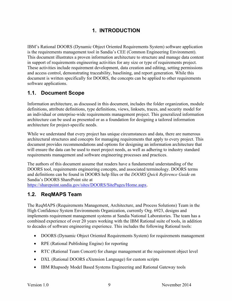
1. INTRODUCTION
IBM’s Rational DOORS (Dynamic Object Oriented Requirements System) software application is the requirements management tool in Sandia’s CEE (Common Engineering Environment). This document illustrates a proven information architecture to structure and manage data content in support of requirements engineering activities for any size or type of requirements project. These activities include requirement development, data creation and editing, setting permissions and access control, demonstrating traceability, baselining, and report generation. While this document is written specifically for DOORS, the concepts can be applied to other requirements software applications.
1.1. Document Scope
Information architecture, as discussed in this document, includes the folder organization, module definitions, attribute definitions, type definitions, views, linksets, traces, and security model for an individual or enterprise-wide requirements management project. This generalized information architecture can be used as presented or as a foundation for designing a tailored information architecture for project-specific needs.
While we understand that every project has unique circumstances and data, there are numerous architectural structures and concepts for managing requirements that apply to every project. This document provides recommendations and options for designing an information architecture that will ensure the data can be used to meet project needs, as well as adhering to industry standard requirements management and software engineering processes and practices.
The authors of this document assume that readers have a fundamental understanding of the DOORS tool, requirements engineering concepts, and associated terminology. DOORS terms and definitions can be found in DOORS help files or the DOORS Quick Reference Guide on Sandia’s DOORS SharePoint site at https://sharepoint.sandia.gov/sites/DOORS/SitePages/Home.aspx.
1.2. ReqMAPS Team
The ReqMAPS (Requirements Management, Architecture, and Process Solutions) Team in the High Confidence System Environments Organization, currently Org. 6923, designs and implements requirement management systems at Sandia National Laboratories. The team has a combined experience of over 20 years working with the IBM Rational suite of tools, in addition to decades of software engineering experience. This includes the following Rational tools:
DOORS (Dynamic Object Oriented Requirements System) for requirements management
RPE (Rational Publishing Engine) for reporting
RTC (Rational Team Concert) for change management at the requirement object level
DXL (Rational DOORS eXtension Language) for custom scripts
IBM Rhapsody Model Based Systems Engineering and Rational Gateway tools
Version 1.0 10 November 2014
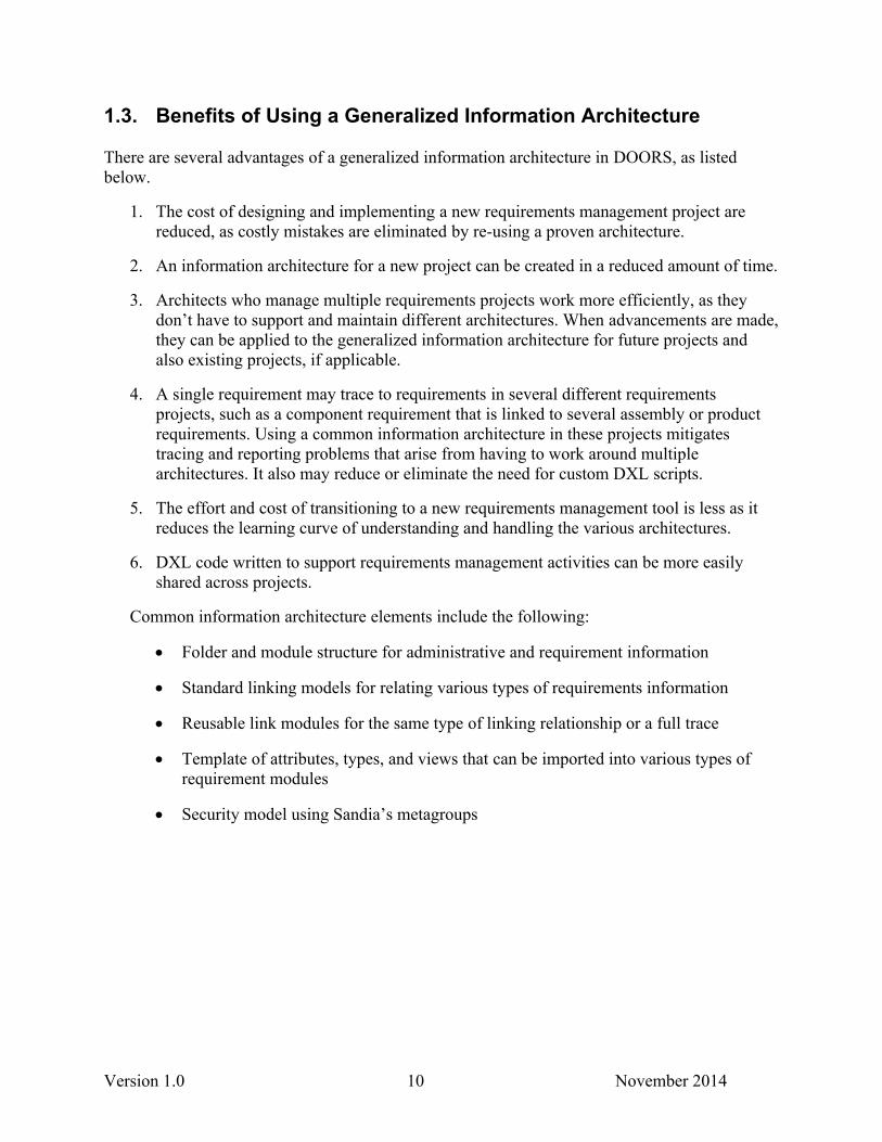
1.3. Benefits of Using a Generalized Information Architecture
There are several advantages of a generalized information architecture in DOORS, as listed below.
1. The cost of designing and implementing a new requirements management project are reduced, as costly mistakes are eliminated by re-using a proven architecture.
2. An information architecture for a new project can be created in a reduced amount of time.
3. Architects who manage multiple requirements projects work more efficiently, as they don’t have to support and maintain different architectures. When advancements are made, they can be applied to the generalized information architecture for future projects and also existing projects, if applicable.
4. A single requirement may trace to requirements in several different requirements projects, such as a component requirement that is linked to several assembly or product requirements. Using a common information architecture in these projects mitigates tracing and reporting problems that arise from having to work around multiple architectures. It also may reduce or eliminate the need for custom DXL scripts.
5. The effort and cost of transitioning to a new requirements management tool is less as it reduces the learning curve of understanding and handling the various architectures.
6. DXL code written to support requirements management activities can be more easily shared across projects.
Common information architecture elements include the following:
Folder and module structure for administrative and requirement information
Standard linking models for relating various types of requirements information
Reusable link modules for the same type of linking relationship or a full trace
Template of attributes, types, and views that can be imported into various types of requirement modules
Security model using Sandia’s metagroups
Version 1.0 11 November 2014
2. INFORMATION ARCHITECTURE DEFINITION
2.1. Project and Folder Structure
DOORS projects and folders are containers of information, specifically formal modules and link modules. Sub-folders may be created that contain several modules.
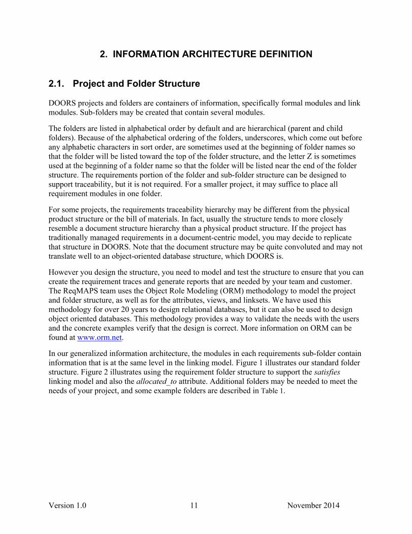
The folders are listed in alphabetical order by default and are hierarchical (parent and child folders). Because of the alphabetical ordering of the folders, underscores, which come out before any alphabetic characters in sort order, are sometimes used at the beginning of folder names so that the folder will be listed toward the top of the folder structure, and the letter Z is sometimes used at the beginning of a folder name so that the folder will be listed near the end of the folder structure. The requirements portion of the folder and sub-folder structure can be designed to support traceability, but it is not required. For a smaller project, it may suffice to place all requirement modules in one folder.
For some projects, the requirements traceability hierarchy may be different from the physical product structure or the bill of materials. In fact, usually the structure tends to more closely resemble a document structure hierarchy than a physical product structure. If the project has traditionally managed requirements in a document-centric model, you may decide to replicate that structure in DOORS. Note that the document structure may be quite convoluted and may not translate well to an object-oriented database structure, which DOORS is.
However you design the structure, you need to model and test the structure to ensure that you can create the requirement traces and generate reports that are needed by your team and customer. The ReqMAPS team uses the Object Role Modeling (ORM) methodology to model the project and folder structure, as well as for the attributes, views, and linksets. We have used this methodology for over 20 years to design relational databases, but it can also be used to design object oriented databases. This methodology provides a way to validate the needs with the users and the concrete examples verify that the design is correct. More information on ORM can be found at www.orm.net.
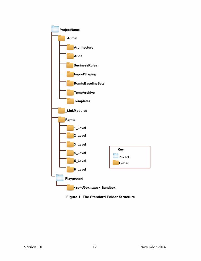
In our generalized information architecture, the modules in each requirements sub-folder contain information that is at the same level in the linking model. Figure 1 illustrates our standard folder structure. Figure 2 illustrates using the requirement folder structure to support the satisfies linking model and also the allocated_to attribute. Additional folders may be needed to meet the needs of your project, and some example folders are described in Table 1.
Version 1.0 12 November 2014
2_Level
Rqmts
6_Level
3_Level
1_Level
ProjectName
_Admin
Audit
TempArchive
Architecture
<sandboxname>_Sandbox
_LinkModules
ImportStaging
Key
Project
Folder
4_Level
5_Level
BusinessRules
Templates
Playground
RqmtsBaselineSets
Figure 1: The Standard Folder Structure
Version 1.0 13 November 2014
Level 2
Level 3
Level 4
Level 1
allocated to
allocated to
allocated to satisfies
satisfies
satisfies
Figure 2: Requirements Folder Structure Supporting Linking Model
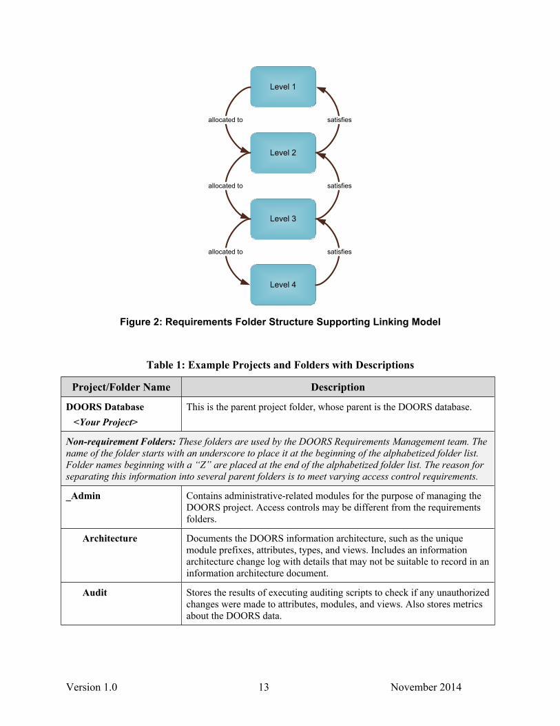
Table 1: Example Projects and Folders with Descriptions
Project/Folder Name Description
DOORS Database <Your Project>
This is the parent project folder, whose parent is the DOORS database.
Non-requirement Folders: These folders are used by the DOORS Requirements Management team. The name of the folder starts with an underscore to place it at the beginning of the alphabetized folder list. Folder names beginning with a “Z” are placed at the end of the alphabetized folder list. The reason for separating this information into several parent folders is to meet varying access control requirements.
_Admin Contains administrative-related modules for the purpose of managing the DOORS project. Access controls may be different from the requirements folders.
Architecture Documents the DOORS information architecture, such as the unique module prefixes, attributes, types, and views. Includes an information architecture change log with details that may not be suitable to record in an information architecture document.
Audit Stores the results of executing auditing scripts to check if any unauthorized changes were made to attributes, modules, and views. Also stores metrics about the DOORS data.
Version 1.0 14 November 2014
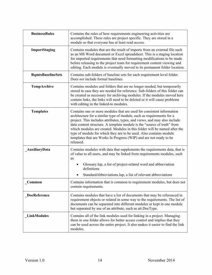
BusinessRules Contains the rules of how requirements engineering activities are accomplished. These rules are project specific. They are stored in a module so that everyone has at least read access.
ImportStaging Contains modules that are the result of imports from an external file such as an MS Word document or Excel spreadsheet. This is a staging location for imported requirements that need formatting modifications to be made before releasing to the project team for requirement content viewing and editing. Each module is eventually moved to its permanent folder location.
RqmtsBaselineSets Contains sub-folders of baseline sets for each requirement level folder. Does not include formal baselines.
TempArchive Contains modules and folders that are no longer needed, but temporarily stored in case they are needed for reference. Sub-folders of this folder can be created as necessary for archiving modules. If the modules moved here contain links, the links will need to be deleted or it will cause problems with editing in the linked-to modules.
Templates Contains one or more modules that are used for consistent information architecture for a similar type of module, such as requirements for a project. This includes attributes, types, and views, and may also include data content structure. A template module is the “source of truth” from which modules are created. Modules in this folder will be named after the type of module for which they are to be used. Also contains module templates that are Works In Progress (WIP) and are not ready to be released.
_AuxiliaryData Contains modules with data that supplements the requirements data, that is of value to all users, and may be linked from requirements modules, such as
Glossary.lup, a list of project-related word and abbreviation definitions
StandardAbbreviations.lup, a list of relevant abbreviations
_Common Contains information that is common to requirement modules, but does not contain requirements.
_DocReference Contains modules that have a list of documents that may be referenced in requirement objects or related in some way to the requirements. The list of documents can be separated into different modules or kept in one module but separated by use of an attribute, such as att.DocType.
_LinkModules Contains all of the link modules used for linking in a project. Managing them in one folder allows for better access control and implies that they can be used across the entire project. It also makes it easier to find the link modules.
Version 1.0 15 November 2014
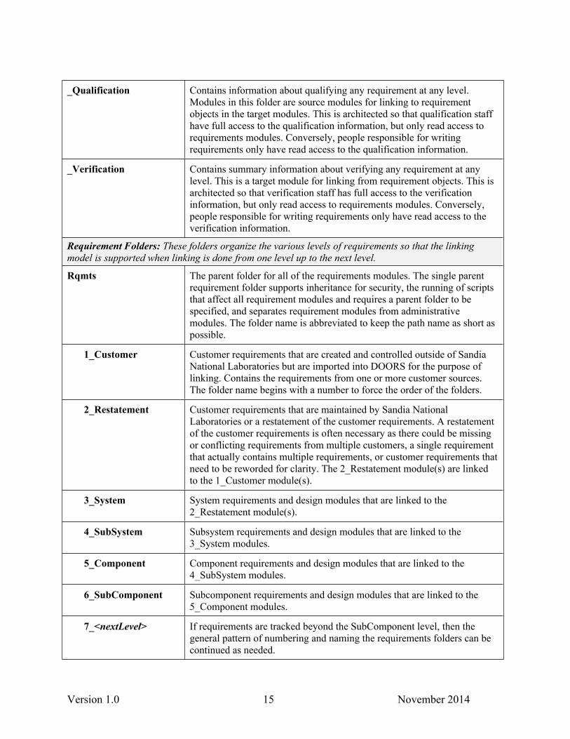
_Qualification Contains information about qualifying any requirement at any level. Modules in this folder are source modules for linking to requirement objects in the target modules. This is architected so that qualification staff have full access to the qualification information, but only read access to requirements modules. Conversely, people responsible for writing requirements only have read access to the qualification information.
_Verification Contains summary information about verifying any requirement at any level. This is a target module for linking from requirement objects. This is architected so that verification staff has full access to the verification information, but only read access to requirements modules. Conversely, people responsible for writing requirements only have read access to the verification information.
Requirement Folders: These folders organize the various levels of requirements so that the linking model is supported when linking is done from one level up to the next level.
Rqmts The parent folder for all of the requirements modules. The single parent requirement folder supports inheritance for security, the running of scripts that affect all requirement modules and requires a parent folder to be specified, and separates requirement modules from administrative modules. The folder name is abbreviated to keep the path name as short as possible.
1_Customer Customer requirements that are created and controlled outside of Sandia National Laboratories but are imported into DOORS for the purpose of linking. Contains the requirements from one or more customer sources. The folder name begins with a number to force the order of the folders.
2_Restatement Customer requirements that are maintained by Sandia National Laboratories or a restatement of the customer requirements. A restatement of the customer requirements is often necessary as there could be missing or conflicting requirements from multiple customers, a single requirement that actually contains multiple requirements, or customer requirements that need to be reworded for clarity. The 2_Restatement module(s) are linked to the 1_Customer module(s).
3_System System requirements and design modules that are linked to the 2_Restatement module(s).
4_SubSystem Subsystem requirements and design modules that are linked to the 3_System modules.
5_Component Component requirements and design modules that are linked to the 4_SubSystem modules.
6_SubComponent Subcomponent requirements and design modules that are linked to the 5_Component modules.
7_<nextLevel> If requirements are tracked beyond the SubComponent level, then the general pattern of numbering and naming the requirements folders can be continued as needed.
Version 1.0 16 November 2014
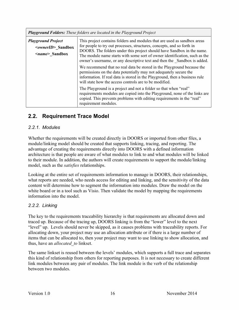
Playground Folders: These folders are located in the Playground Project
Playground Project<ownerID>_Sandbox<name>_Sandbox
This project contains folders and modules that are used as sandbox areas for people to try out processes, structures, concepts, and so forth in DOORS. The folders under this project should have Sandbox in the name. The module name starts with some sort of owner identification, such as the owner’s username, or any descriptive text and then the _Sandbox is added. We recommend that no real data be stored in the Playground because the permissions on the data potentially may not adequately secure the information. If real data is stored in the Playground, then a business rule will state how the access controls are to be modified.The Playground is a project and not a folder so that when “real” requirements modules are copied into the Playground, none of the links are copied. This prevents problems with editing requirements in the “real” requirement modules.
2.2. Requirement Trace Model
2.2.1. Modules
Whether the requirements will be created directly in DOORS or imported from other files, a module/linking model should be created that supports linking, tracing, and reporting. The advantage of creating the requirements directly into DOORS with a defined information architecture is that people are aware of what modules to link to and what modules will be linked to their module. In addition, the authors will create requirements to support the module/linking model, such as the satisfies relationships.
Looking at the entire set of requirements information to manage in DOORS, their relationships, what reports are needed, who needs access for editing and linking, and the sensitivity of the data content will determine how to segment the information into modules. Draw the model on the white board or in a tool such as Visio. Then validate the model by mapping the requirements information into the model.
2.2.2. Linking
The key to the requirements traceability hierarchy is that requirements are allocated down and traced up. Because of the tracing up, DOORS linking is from the “lower” level to the next “level” up. Levels should never be skipped, as it causes problems with traceability reports. For allocating down, your project may use an allocation attribute or if there is a large number of items that can be allocated to, then your project may want to use linking to show allocation, and thus, have an allocated_to linkset.
The same linkset is reused between the levels’ modules, which supports a full trace and separates this kind of relationship from others for reporting purposes. It is not necessary to create different link modules between any pair of modules. The link module is the verb of the relationship between two modules.
Version 1.0 17 November 2014
The direction of the linkset is important because the linking data is stored in the source module. Thus, people who are linking need at least create, modify, and delete permissions in the source module. Read access is all that is needed for the target module. However, as far as traceability is concerned, the direction of the linksets is not important. We’ve already indicated that you “link up” for the standard satisfies trace. But other relationships between the same modules can have linksets created in the opposite direction. While this might seem “wrong” at first, it is perfectly acceptable.
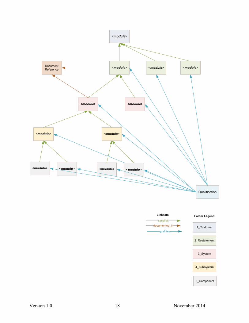
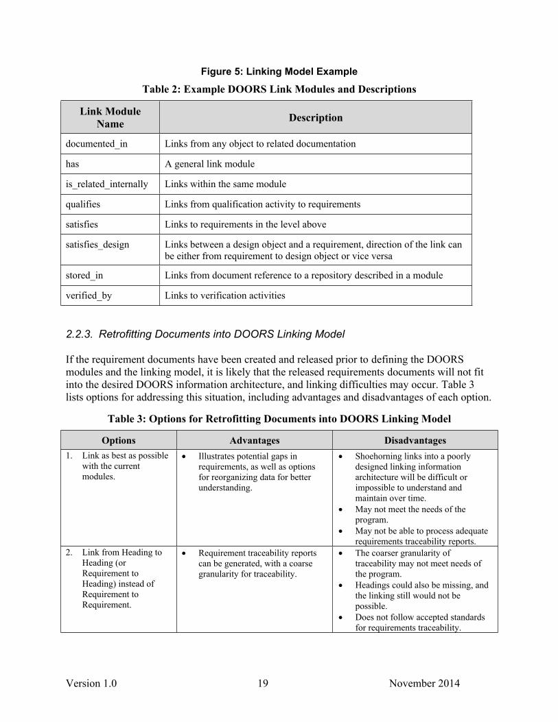
We have included a conceptual model shown in Figure 5 that can be used as an example of linksets used for traceability with qualification, documentation, and requirement information. Note that the information is “linked up” for the satisfies relationships. Therefore, modules in the lowest level of the relationship pair are the source modules. However, the Qualification module is the source module, which is designed to support access control needs. The DocumentReference module is the target module for all of the requirements modules.
All linksets should be explicitly created in DOORS, following the linkset definitions illustrated in the linking model, in the production environment prior to any linking activities. If a linkset has not been created prior to linking, DOORS will create a default DOORS link module. This default link module should never be used. An auditing script can be used to find and delete these default link modules that were erroneously created, after testing ensures that no links have been created using these default link modules.
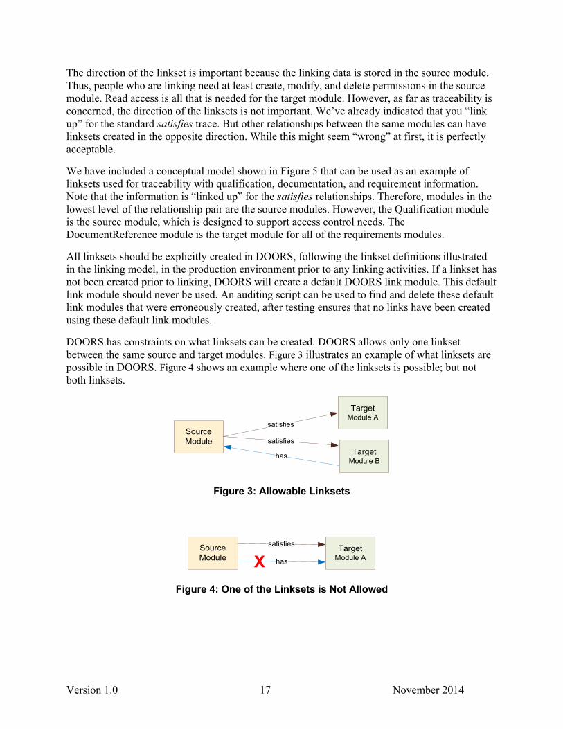
DOORS has constraints on what linksets can be created. DOORS allows only one linkset between the same source and target modules. Figure 3 illustrates an example of what linksets are possible in DOORS. Figure 4 shows an example where one of the linksets is possible; but not both linksets.
SourceModule
TargetModule A
satisfies
TargetModule B
satisfies
has
Figure 3: Allowable Linksets
SourceModule
TargetModule A
satisfies
hasXFigure 4: One of the Linksets is Not Allowed
Version 1.0 18 November 2014
<module>
<module>
<module>
<module>
<module>
<module>
Document Reference
1_Customer
2_Restatement
3_System
4_SubSystem
Folder Legend
Qualification
<module> <module>
Linksets
satisfies
documented_in
qualifies
5_Component
<module> <module> <module> <module>
Version 1.0 19 November 2014
Figure 5: Linking Model Example
Table 2: Example DOORS Link Modules and Descriptions
Link Module Name Description
documented_in Links from any object to related documentation
has A general link module
is_related_internally Links within the same module
qualifies Links from qualification activity to requirements
satisfies Links to requirements in the level above
satisfies_design Links between a design object and a requirement, direction of the link can be either from requirement to design object or vice versa
stored_in Links from document reference to a repository described in a module
verified_by Links to verification activities
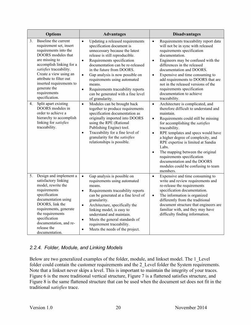
2.2.3. Retrofitting Documents into DOORS Linking Model
If the requirement documents have been created and released prior to defining the DOORS modules and the linking model, it is likely that the released requirements documents will not fit into the desired DOORS information architecture, and linking difficulties may occur. Table 3 lists options for addressing this situation, including advantages and disadvantages of each option.
Table 3: Options for Retrofitting Documents into DOORS Linking Model
Options Advantages Disadvantages1. Link as best as possible
with the current modules.
Illustrates potential gaps in requirements, as well as options for reorganizing data for better understanding.
Shoehorning links into a poorly designed linking information architecture will be difficult or impossible to understand and maintain over time.
May not meet the needs of the program.
May not be able to process adequate requirements traceability reports.
2. Link from Heading to Heading (or Requirement to Heading) instead of Requirement to Requirement.
Requirement traceability reports can be generated, with a coarse granularity for traceability.
The coarser granularity of traceability may not meet needs of the program.
Headings could also be missing, and the linking still would not be possible.
Does not follow accepted standards for requirements traceability.
Version 1.0 20 November 2014
Options Advantages Disadvantages3. Baseline the current
requirement set, insert requirements into the DOORS modules that are missing to accomplish linking for a satisfies traceability. Create a view using an attribute to filter out inserted requirements to generate the requirements specification.
Updating a released requirements specification document is unnecessary because the latest release is still reproducible.
Requirements specification documentation can be re-released in the future from DOORS.
Gap analysis is now possible on requirements using automated means.
Requirements traceability reports can be generated with a fine level of granularity.
Requirements traceability report data will not be in sync with released requirements specification documentation.
Engineers may be confused with the differences in the released documentation and DOORS.
Expensive and time consuming to add requirements to DOORS that are not in the released versions of the requirements specification documentation to achieve traceability.
4. Split apart existing DOORS modules in order to achieve a hierarchy to accomplish linking for satisfies traceability.
Modules can be brought back together to produce requirements specification documentation as originally imported into DOORS using the RPE (Rational Publishing Engine) tool.
Traceability for a fine level of granularity for the satisifies relationships is possible.
Architecture is complicated, and therefore difficult to understand and maintain.
Requirements could still be missing for accomplishing the satisfies traceability.
RPE templates and specs would have a higher degree of complexity, and RPE expertise is limited at Sandia Labs.
The mapping between the original requirements specification documentation and the DOORS modules could be confusing to team members.
5. Design and implement a satisfactory linking model, rewrite the requirements specification documentation using DOORS, link the requirements, generate the requirements specification documentation, and re-release the documentation.
Gap analysis is possible on requirements using automated means.
Requirements traceability reports can be generated at a fine level of granularity.
Architecture, specifically the linking model, is easy to understand and maintain.
Meets the general standards of requirement traceability.
Meets the needs of the project.
Expensive and time consuming to write and review requirements and re-release the requirements specification documentation.
The information is organized differently from the traditional document structure that engineers are familiar with, and they may have difficulty finding information.
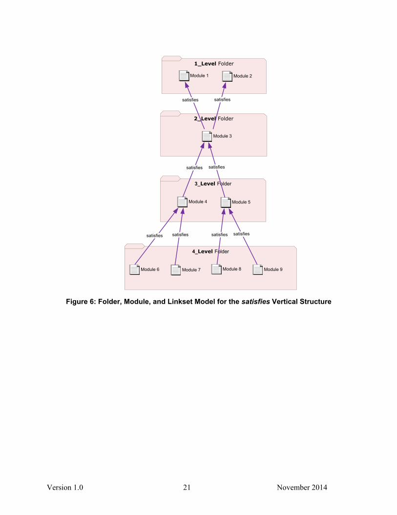
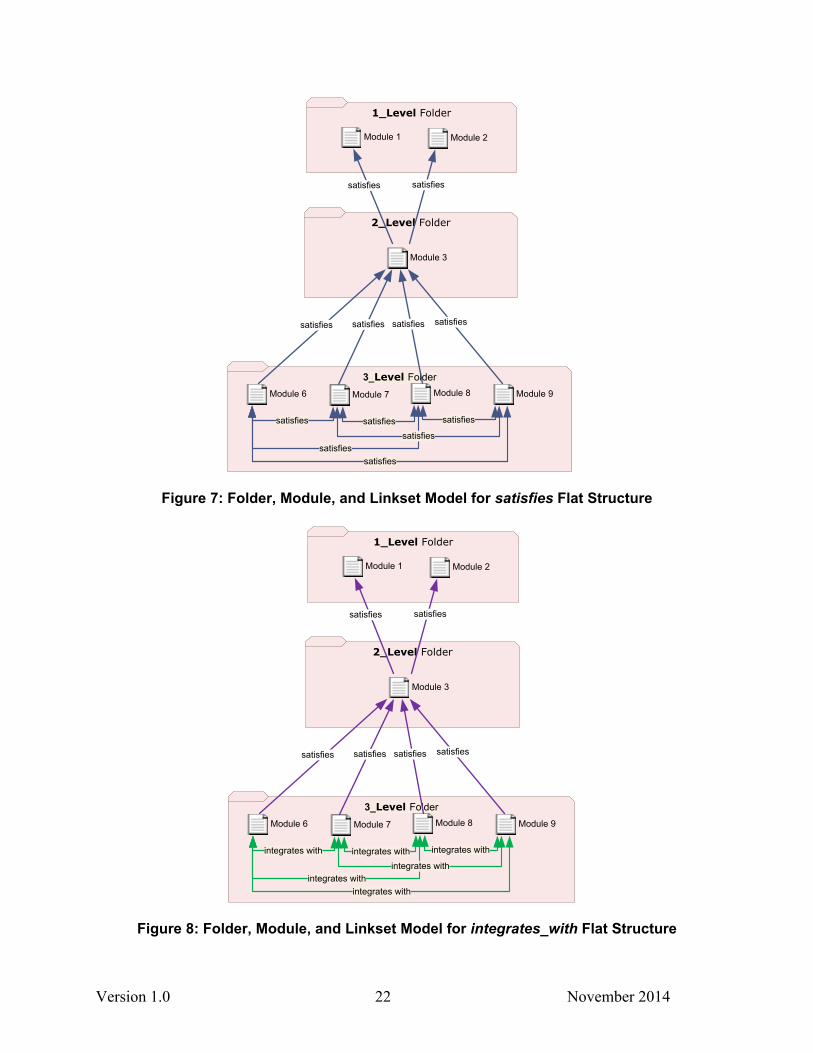
2.2.4. Folder, Module, and Linking Models
Below are two generalized examples of the folder, module, and linkset model. The 1_Level folder could contain the customer requirements and the 2_Level folder the System requirements. Note that a linkset never skips a level. This is important to maintain the integrity of your traces. Figure 6 is the more traditional vertical structure, Figure 7 is a flattened satisfies structure, and Figure 8 is the same flattened structure that can be used when the document set does not fit in the traditional satisfies trace.
Version 1.0 21 November 2014
3_Level Folder
2_Level Folder
1_Level Folder
satisfies
Module 1 Module 2
Module 3
satisfies
Module 4 Module 5
satisfies satisfies
4_Level Folder
Module 6 Module 7 Module 8 Module 9
satisfies satisfies satisfies satisfies
Figure 6: Folder, Module, and Linkset Model for the satisfies Vertical Structure
Version 1.0 22 November 2014
3_Level Folder
2_Level Folder
1_Level Folder
satisfies
Module 1 Module 2
Module 3
satisfies
Module 6 Module 7 Module 8 Module 9
satisfies satisfies satisfies satisfies
satisfies satisfiessatisfies
satisfiessatisfies
satisfies
Figure 7: Folder, Module, and Linkset Model for satisfies Flat Structure
3_Level Folder
2_Level Folder
1_Level Folder
satisfies
Module 1 Module 2
Module 3
satisfies
Module 6 Module 7 Module 8 Module 9
satisfies satisfies satisfies satisfies
integrates with integrates withintegrates with
integrates withintegrates with
integrates with
Figure 8: Folder, Module, and Linkset Model for integrates_with Flat Structure
Version 1.0 23 November 2014
2.2.5. Linking with DOORS Tables
We recommend that projects not use the table functionality built into DOORS. DOORS tables cause problems with linking to requirements stored in table cells and generating accurate traceability reports with RPE. In addition, contextual information is lost by linking to a table cell, as the table name and column headings are not shown in traceability reports.
Each requirement stored in DOORS tables should be entered as an individual, stand-alone requirement object in a DOORS module. However, there may be a visual value in displaying the information in a table format for the viewers. If that is the case, the information can also be formatted in a table, saved as a graphic, and imported into DOORS. The key is to ensure that the data in the table is in sync with the individual requirement objects. If they become out of sync, the individual requirement object is considered to be the correct version. If the syncing problem continues, the graphic should be deleted from DOORS to avoid confusion.
2.3. Access Control and Permissions
2.3.1. Designing the Security Model
Designing the access control model cannot be done in isolation. All factors must be considered simultaneously while understanding project or program priorities for managing the information and include the following:
1. The project/folder/module structure
2. The NTK (need-to-know) constraints placed on the data
3. Roles people play on the project, which define their responsibilities and permissions in DOORS
A viable security model balances appropriate access with the ability to maintain the implemented security model. The DOORS access inheritance feature is used whenever possible to minimize the administrative burden of maintaining the implemented security model. Therefore, any break in the access inheritance is kept as high in the folder hierarchy as possible. We recommend that all modules inherit the access control from its parent folder. All objects in modules inherit the security controls from its parent module. A compelling argument needs to be established to override this rule, and it needs to be well documented because having security controls on objects within a module requires significantly more maintenance.
Here are some considerations for designing the security model that are especially applicable to a large or compartmentalized project.
Using the information gathered on the roles and responsibilities of the project team members and the security risk analysis, a security model for controlling access and permissions on the data content can be superimposed on the folder, module, and linking models. Adjustments to both models can be made, based on the project’s priorities.
Note that the DOORS permissions do not distinguish between permission to create, modify, and delete requirement data content with permissions to create, modify, and delete information architecture elements, such as attributes and linksets. If the project has
Version 1.0 24 November 2014
assigned different people the responsibilities for requirements development from requirements management, DOORS will still allow anyone who has create, modify, and delete permissions in a module to modify both data content and architecture.
While there is no way that unauthorized information architecture changes can be prevented by requirement developers, we do have a set of DXL scripts that can be periodically run against the DOORS projects, folders, and modules to find any unauthorized or non-standard changes to the architecture. Once the changes have been identified, the requirements management team can follow through with the requirement developers to determine the following:
Why the changes were made
Potentially incorporate those changes throughout the information architecture to meet users’ needs (going through the information architecture change management process)
Explain why the changes would cause harm to the project information architecture and then correct those changes.
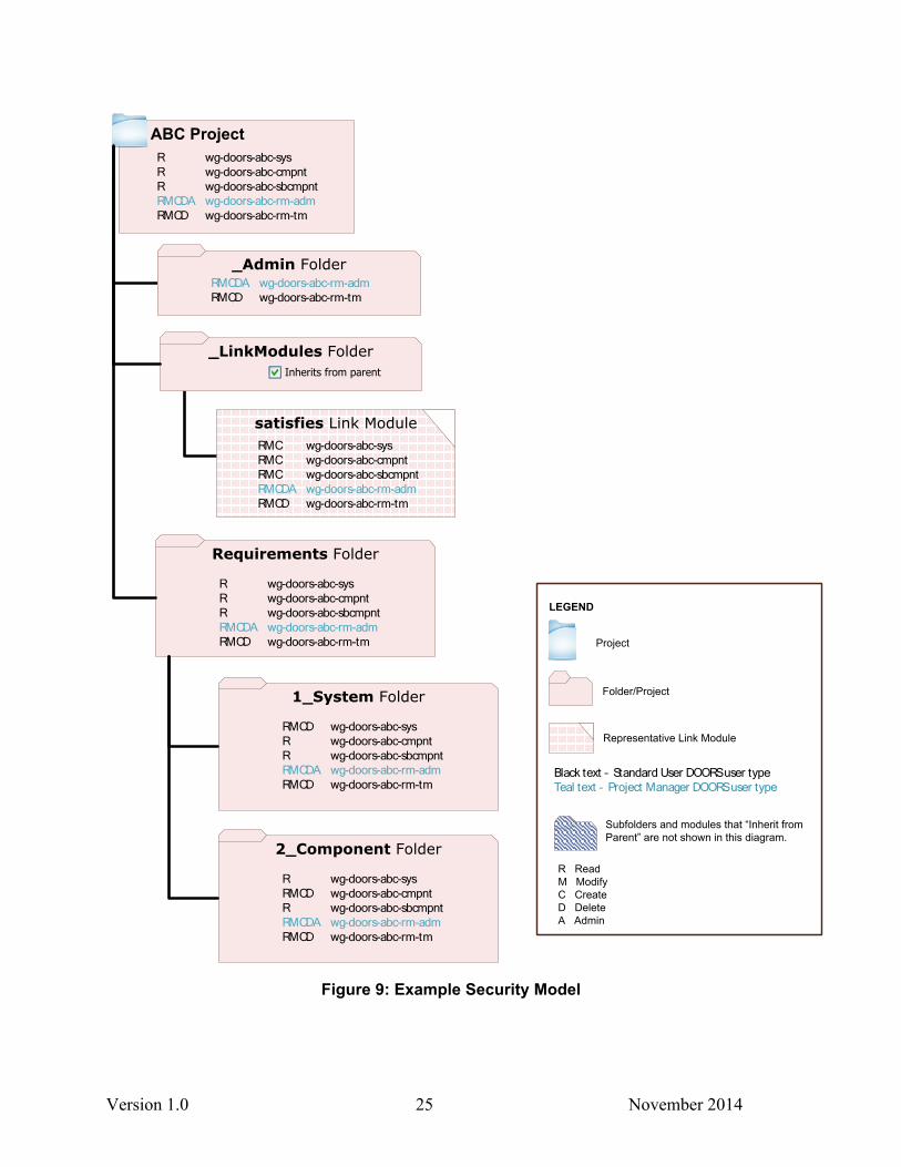
Figure 9 illustrates a security model for a small project using the DOORS permissions (Read, Modify, Create, Delete, and Administer) and Sandia’s metagroups. Note that the security controls are inherited from the top project; therefore, a metagroup must be listed with at least Read permissions in the top project. The inheritance can be broken, as illustrated with the different permissions and metagroups in the _Admin folder from the ABC Project.
This model also identifies the DOORS user types, which is assigned to each user by the tool administrator. Typically requirement developers are Standard Users; information architects are Project Managers; and tool administrators are Database Managers.
Version 1.0 25 November 2014
_Admin Folder
ABC ProjectR wg-doors-abc-sysR wg-doors-abc-cmpntR wg-doors-abc-sbcmpntRMCDA wg-doors-abc-rm-admRMCD wg-doors-abc-rm-tm
RMCDA wg-doors-abc-rm-admRMCD wg-doors-abc-rm-tm
_LinkModules FolderInherits from parent
satisfies Link ModuleRMC wg-doors-abc-sysRMC wg-doors-abc-cmpntRMC wg-doors-abc-sbcmpntRMCDA wg-doors-abc-rm-admRMCD wg-doors-abc-rm-tm
Requirements Folder
R wg-doors-abc-sysR wg-doors-abc-cmpntR wg-doors-abc-sbcmpntRMCDA wg-doors-abc-rm-admRMCD wg-doors-abc-rm-tm
1_System Folder
RMCD wg-doors-abc-sysR wg-doors-abc-cmpntR wg-doors-abc-sbcmpntRMCDA wg-doors-abc-rm-admRMCD wg-doors-abc-rm-tm
2_Component Folder
R wg-doors-abc-sysRMCD wg-doors-abc-cmpntR wg-doors-abc-sbcmpntRMCDA wg-doors-abc-rm-admRMCD wg-doors-abc-rm-tm
LEGEND
Project
Representative Link Module
Folder/Project
Black text – Standard User DOORS user typeTeal text – Project Manager DOORS user type
Subfolders and modules that “Inherit from Parent” are not shown in this diagram.
R ReadM ModifyC CreateD DeleteA Admin
Figure 9: Example Security Model
Version 1.0 26 November 2014
2.3.2. Security Model Rules and Assumptions
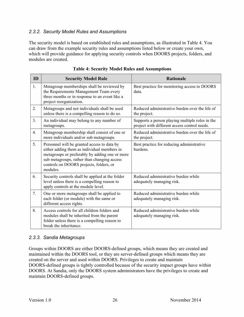
The security model is based on established rules and assumptions, as illustrated in Table 4. You can draw from the example security rules and assumptions listed below or create your own, which will provide guidance for applying security controls when DOORS projects, folders, and modules are created.
Table 4: Security Model Rules and Assumptions
ID Security Model Rule Rationale1. Metagroup memberships shall be reviewed by
the Requirements Management Team every three months or in response to an event like a project reorganization.
Best practice for monitoring access to DOORS data.
2. Metagroups and not individuals shall be used unless there is a compelling reason to do so.
Reduced administrative burden over the life of the project.
3. An individual may belong to any number of metagroups.
Supports a person playing multiple roles in the project with different access control needs.
4. Metagroup membership shall consist of one or more individuals and/or sub metagroups.
Reduced administrative burden over the life of the project.
5. Personnel will be granted access to data by either adding them as individual members in metagroups or preferably by adding one or more sub metagroups, rather than changing access controls on DOORS projects, folders, or modules.
Best practice for reducing administrative burdens.
6. Security controls shall be applied at the folder level unless there is a compelling reason to apply controls at the module level.
Reduced administrative burden while adequately managing risk.
7. One or more metagroups shall be applied to each folder (or module) with the same or different access rights.
Reduced administrative burden while adequately managing risk.
8. Access controls for all children folders and modules shall be inherited from the parent folder unless there is a compelling reason to break the inheritance.
Reduced administrative burden while adequately managing risk.
2.3.3. Sandia Metagroups
Groups within DOORS are either DOORS-defined groups, which means they are created and maintained within the DOORS tool, or they are server-defined groups which means they are created on the server and used within DOORS. Privileges to create and maintain DOORS-defined groups is tightly controlled because of the security impact groups have within DOORS. At Sandia, only the DOORS system administrators have the privileges to create and maintain DOORS-defined groups.
Version 1.0 27 November 2014
We use Sandia’s Metagroup Utility for creating and maintaining groups on computers on the Sandia Restricted Network (SRN) and Sandia Classified Network (SCN). The Sandia Metagroup Utility can be used in combination with the server-defined groups within DOORS to define and maintain DOORS access control groups for a DOORS project. This eases the burden on the DOORS Database Managers because they do not have to manage the groups for a DOORS project other than adding a metagroup name to the list of groups. The burden of defining and maintaining the Metagroups lies with the project.
2.4.4. DOORS Group for External Users
If non-Sandians need access to an SCN DOORS project, a DOORS-defined group is needed that includes the names of non-Sandians that use the DOORS Web tool to access the Sandia DOORS via the Enterprise Secure Network (ESN.) Because of the way the ESN provides access to non-Sandians, there is a username mismatch between what DOORS understands for the user and what ESN provides. The Metagroup Utility uses the username specified by ESN which is not recognized by DOORS; thus, we have to enter the username understood by DOORS within a DOORS group.
2.3.5. Logical Metagroups on SCN
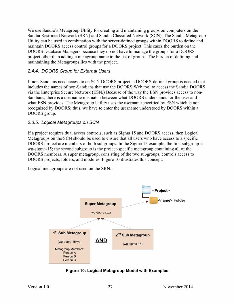
If a project requires dual access controls, such as Sigma 15 and DOORS access, then Logical Metagroups on the SCN should be used to ensure that all users who have access to a specific DOORS project are members of both subgroups. In the Sigma 15 example, the first subgroup is wg-sigma-15; the second subgroup is the project-specific metagroup containing all of the DOORS members. A super metagroup, consisting of the two subgroups, controls access to DOORS projects, folders, and modules. Figure 10 illustrates this concept.
Logical metagroups are not used on the SRN.
<Project>
<name> FolderSuper Metagroup
(wg-doors-xyz)
1st Sub Metagroup
(wg-doors-15xyz)
Metagroup Members:Person APerson BPerson C
2nd Sub Metagroup
(wg-sigma-15)AND
Figure 10: Logical Metagroup Model with Examples
Version 1.0 28 November 2014
2.4.6. Metagroup Naming Standards
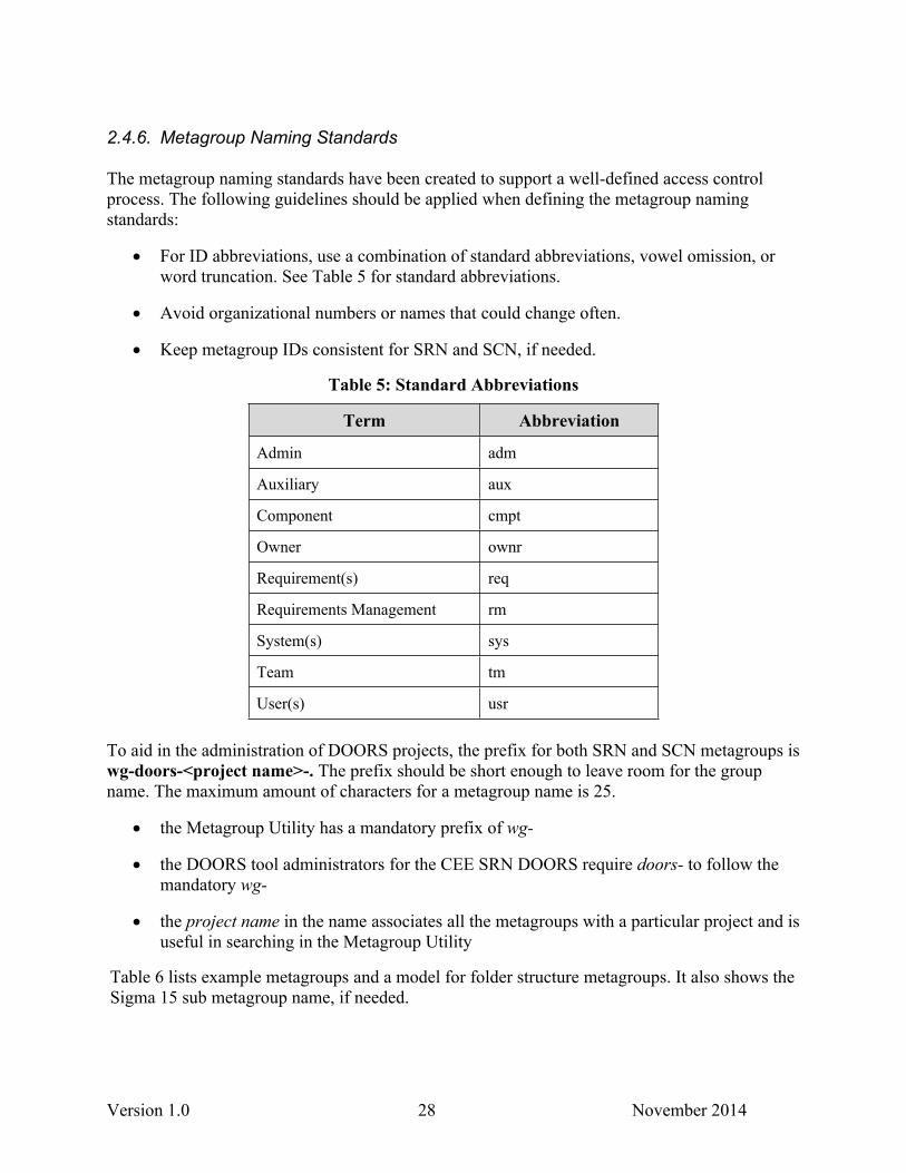
The metagroup naming standards have been created to support a well-defined access control process. The following guidelines should be applied when defining the metagroup naming standards:
For ID abbreviations, use a combination of standard abbreviations, vowel omission, or word truncation. See Table 5 for standard abbreviations.
Avoid organizational numbers or names that could change often.
Keep metagroup IDs consistent for SRN and SCN, if needed.
Table 5: Standard Abbreviations
Term Abbreviation
Admin adm
Auxiliary aux
Component cmpt
Owner ownr
Requirement(s) req
Requirements Management rm
System(s) sys
Team tm
User(s) usr
To aid in the administration of DOORS projects, the prefix for both SRN and SCN metagroups is wg-doors-<project name>-. The prefix should be short enough to leave room for the group name. The maximum amount of characters for a metagroup name is 25.
the Metagroup Utility has a mandatory prefix of wg-
the DOORS tool administrators for the CEE SRN DOORS require doors- to follow the mandatory wg-
the project name in the name associates all the metagroups with a particular project and is useful in searching in the Metagroup Utility
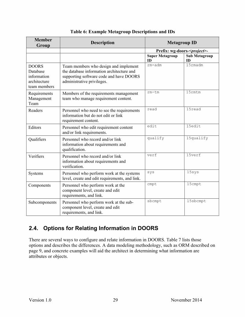
Table 6 lists example metagroups and a model for folder structure metagroups. It also shows the Sigma 15 sub metagroup name, if needed.
Version 1.0 29 November 2014
Table 6: Example Metagroup Descriptions and IDs
Member Group Description Metagroup ID
Prefix: wg-doors-<project>-Super Metagroup ID
Sub Metagroup ID
DOORS Database information architecture team members
Team members who design and implement the database information architecture and supporting software code and have DOORS administrative privileges.
rm-adm 15rmadm
Requirements Management Team
Members of the requirements management team who manage requirement content.
rm-tm 15rmtm
Readers Personnel who need to see the requirements information but do not edit or link requirement content.
read 15read
Editors Personnel who edit requirement content and/or link requirements.
edit 15edit
Qualifiers Personnel who record and/or link information about requirements and qualification.
qualify 15qualify
Verifiers Personnel who record and/or link information about requirements and verification.
verf 15verf
Systems Personnel who perform work at the systems level, create and edit requirements, and link.
sys 15sys
Components Personnel who perform work at the component level, create and edit requirements, and link.
cmpt 15cmpt
Subcomponents Personnel who perform work at the sub-component level, create and edit requirements, and link.
sbcmpt 15sbcmpt
2.4. Options for Relating Information in DOORS
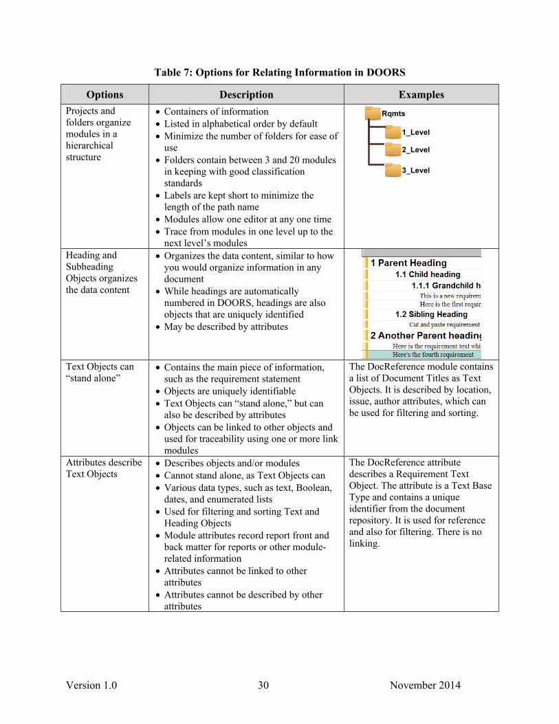
There are several ways to configure and relate information in DOORS. Table 7 lists those options and describes the differences. A data modeling methodology, such as ORM described on page 9, and concrete examples will aid the architect in determining what information are attributes or objects.
Version 1.0 30 November 2014
Table 7: Options for Relating Information in DOORS
Options Description ExamplesProjects and folders organize modules in a hierarchical structure
Containers of information Listed in alphabetical order by default Minimize the number of folders for ease of
use Folders contain between 3 and 20 modules
in keeping with good classification standards
Labels are kept short to minimize the length of the path name
Modules allow one editor at any one time Trace from modules in one level up to the
next level’s modules
2_Level
Rqmts
3_Level
1_Level
Heading and Subheading Objects organizes the data content
Organizes the data content, similar to how you would organize information in any document
While headings are automatically numbered in DOORS, headings are also objects that are uniquely identified
May be described by attributes
Text Objects can “stand alone”
Contains the main piece of information, such as the requirement statement
Objects are uniquely identifiable Text Objects can “stand alone,” but can
also be described by attributes Objects can be linked to other objects and
used for traceability using one or more link modules
The DocReference module contains a list of Document Titles as Text Objects. It is described by location, issue, author attributes, which can be used for filtering and sorting.
Attributes describe Text Objects
Describes objects and/or modules Cannot stand alone, as Text Objects can Various data types, such as text, Boolean,
dates, and enumerated lists Used for filtering and sorting Text and
Heading Objects Module attributes record report front and
back matter for reports or other module-related information
Attributes cannot be linked to other attributes
Attributes cannot be described by other attributes
The DocReference attribute describes a Requirement Text Object. The attribute is a Text Base Type and contains a unique identifier from the document repository. It is used for reference and also for filtering. There is no linking.
Version 1.0 31 November 2014
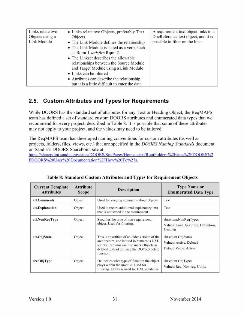
Links relate two Objects using a Link Module
Links relate two Objects, preferably Text Objects
The Link Module defines the relationship The Link Module is stated as a verb, such
as Rqmt 1 satisfies Rqmt 2. The Linkset describes the allowable
relationships between the Source Module and Target Module using a Link Module
Links can be filtered Attributes can describe the relationship,
but it is a little difficult to enter the data
A requirement text object links to a DocReference text object, and it is possible to filter on the links.
2.5. Custom Attributes and Types for Requirements
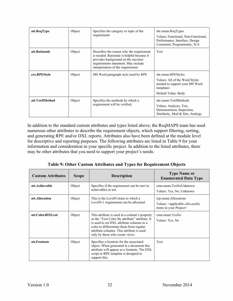
While DOORS has the standard set of attributes for any Text or Heading Object, the ReqMAPS team has defined a set of standard custom DOORS attributes and enumerated data types that we recommend for every project, described in Table 8. It is possible that some of these attributes may not apply to your project, and the values may need to be tailored.
The ReqMAPS team has developed naming conventions for custom attributes (as well as projects, folders, files, views, etc.) that are specified in the DOORS Naming Standards document on Sandia’s DOORS SharePoint site at https://sharepoint.sandia.gov/sites/DOORS/SitePages/Home.aspx?RootFolder=%2Fsites%2FDOORS%2FDOORS%20User%20Documentation%2FHow%20To%27s.
Table 8: Standard Custom Attributes and Types for Requirement Objects
Current Template Attributes
Attribute Scope Description Type Name or
Enumerated Data Type
att.Comments Object Used for keeping comments about objects. Text
att.Explanation Object Used to record additional explanatory text that is not stated in the requirement
Text
att.NonReqType Object Specifies the type of non-requirement object. Used for filtering.
shr.enum.NonReqTypesValues: Goal, Assertion, Definition, Heading
att.ObjState Object This is an artifact of an older version of the architecture, and is used in numerous DXL scripts. Can also use it to mark Objects as deleted instead of using the DOORS delete function.
shr.enum.ObjStatesValues: Active, DeletedDefault Value: Active
cre.ObjType Object Delineates what type of function the object plays within the module. Used for filtering. Utility is used for DXL attributes.
shr.enum.ObjTypesValues: Req, Non-req, Utility
Version 1.0 32 November 2014
att.ReqType Object Specifies the category or topic of the requirement.
shr.enum.ReqTypesValues: Functional, Non-Functional, Performance, Interface, Design Constraint, Programmatic, N/A
att.Rationale Object Describes the reason why the requirement is needed. Rationale is helpful because it provides background on the succinct requirements statement. May include interpretation of the requirement.
Text
cre.RPEStyle Object MS Word paragraph style used by RPE shr.enum.RPEStylesValues: All of the Word Styles needed to support your MS Word templatesDefault Value: Body
att.VerifMethod Object Specifies the methods by which a requirement will be verified.
shr.enum.VerifMethodsValues: Analysis, Test, Demonstration, Inspection, Similarity, Mod & Sim, Analogy
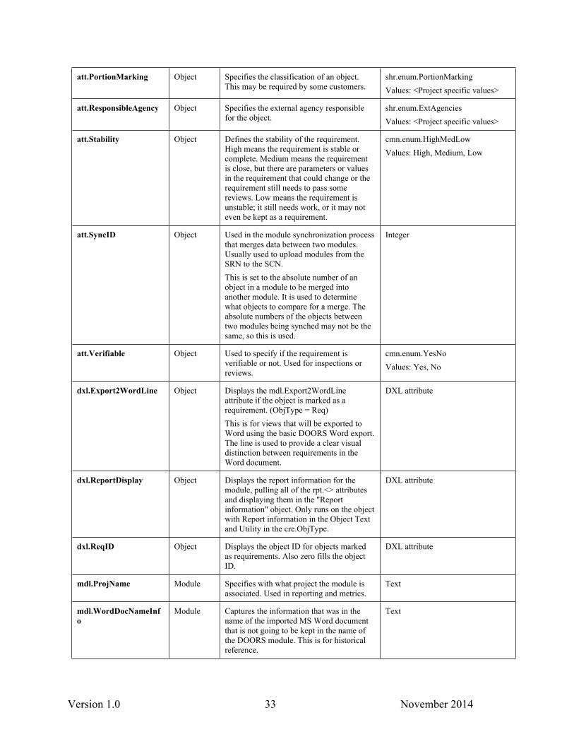
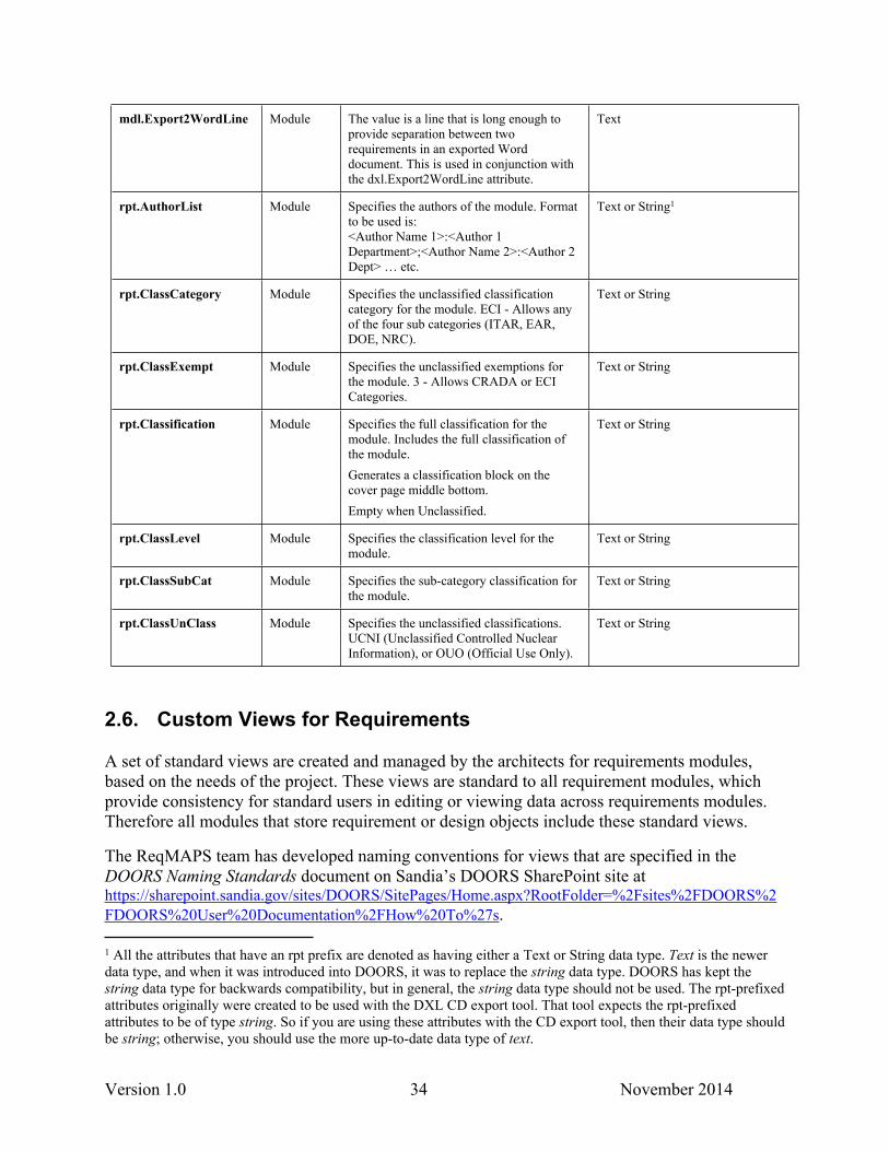
In addition to the standard custom attributes and types listed above, the ReqMAPS team has used numerous other attributes to describe the requirement objects, which support filtering, sorting, and generating RPE and/or DXL reports. Attributes also have been defined at the module level for descriptive and reporting purposes. The following attributes are listed in Table 9 for your information and consideration in your specific project. In addition to the listed attributes, there may be other attributes that you need to support your project’s needs.
Table 9: Other Custom Attributes and Types for Requirement Objects
Custom Attributes Scope Description Type Name or Enumerated Data Type
att.Achievable Object Specifies if the requirement can be met (is achievable) or not.
cmn.enum.YesNoUnknownValues: Yes, No, Unknown
att.Allocation Object This is the LevelN items to which a LevelN-1 requirement can be allocated.
typ.enum.AllocationsValues: <applicable allocatable items in your Project>
att.Color4DXLcol Object This attribute is used in a column’s property as the “Text Color By attribute” attribute. It is used to set DXL attribute columns to a color to differentiate them from regular attribute columns. This attribute is used only by those who create views.
cmn.enum.YesNoValues: Yes, No
att.Footnote Object Specifies a footnote for the associated object. When generated in a document this attribute will appear as a footnote. The DXL script or RPE template is designed to support this.
Text
Version 1.0 33 November 2014
att.PortionMarking Object Specifies the classification of an object. This may be required by some customers.
shr.enum.PortionMarkingValues: <Project specific values>
att.ResponsibleAgency Object Specifies the external agency responsible for the object.
shr.enum.ExtAgenciesValues: <Project specific values>
att.Stability Object Defines the stability of the requirement. High means the requirement is stable or complete. Medium means the requirement is close, but there are parameters or values in the requirement that could change or the requirement still needs to pass some reviews. Low means the requirement is unstable; it still needs work, or it may not even be kept as a requirement.
cmn.enum.HighMedLowValues: High, Medium, Low
att.SyncID Object Used in the module synchronization process that merges data between two modules. Usually used to upload modules from the SRN to the SCN.This is set to the absolute number of an object in a module to be merged into another module. It is used to determine what objects to compare for a merge. The absolute numbers of the objects between two modules being synched may not be the same, so this is used.
Integer
att.Verifiable Object Used to specify if the requirement is verifiable or not. Used for inspections or reviews.
cmn.enum.YesNoValues: Yes, No
dxl.Export2WordLine Object Displays the mdl.Export2WordLine attribute if the object is marked as a requirement. (ObjType = Req)This is for views that will be exported to Word using the basic DOORS Word export. The line is used to provide a clear visual distinction between requirements in the Word document.
DXL attribute
dxl.ReportDisplay Object Displays the report information for the module, pulling all of the rpt.<> attributes and displaying them in the "Report information" object. Only runs on the object with Report information in the Object Text and Utility in the cre.ObjType.
DXL attribute
dxl.ReqID Object Displays the object ID for objects marked as requirements. Also zero fills the object ID.
DXL attribute
mdl.ProjName Module Specifies with what project the module is associated. Used in reporting and metrics.
Text
mdl.WordDocNameInfo
Module Captures the information that was in the name of the imported MS Word document that is not going to be kept in the name of the DOORS module. This is for historical reference.
Text
Version 1.0 34 November 2014
mdl.Export2WordLine Module The value is a line that is long enough to provide separation between two requirements in an exported Word document. This is used in conjunction with the dxl.Export2WordLine attribute.
Text
rpt.AuthorList Module Specifies the authors of the module. Format to be used is: <Author Name 1>:<Author 1 Department>;<Author Name 2>:<Author 2 Dept> … etc.
Text or String1
rpt.ClassCategory Module Specifies the unclassified classification category for the module. ECI - Allows any of the four sub categories (ITAR, EAR, DOE, NRC).
Text or String
rpt.ClassExempt Module Specifies the unclassified exemptions for the module. 3 - Allows CRADA or ECI Categories.
Text or String
rpt.Classification Module Specifies the full classification for the module. Includes the full classification of the module.Generates a classification block on the cover page middle bottom.Empty when Unclassified.
Text or String
rpt.ClassLevel Module Specifies the classification level for the module.
Text or String
rpt.ClassSubCat Module Specifies the sub-category classification for the module.
Text or String
rpt.ClassUnClass Module Specifies the unclassified classifications. UCNI (Unclassified Controlled Nuclear Information), or OUO (Official Use Only).
Text or String
2.6. Custom Views for Requirements
A set of standard views are created and managed by the architects for requirements modules, based on the needs of the project. These views are standard to all requirement modules, which provide consistency for standard users in editing or viewing data across requirements modules. Therefore all modules that store requirement or design objects include these standard views.
The ReqMAPS team has developed naming conventions for views that are specified in the DOORS Naming Standards document on Sandia’s DOORS SharePoint site at https://sharepoint.sandia.gov/sites/DOORS/SitePages/Home.aspx?RootFolder=%2Fsites%2FDOORS%2FDOORS%20User%20Documentation%2FHow%20To%27s.
1 All the attributes that have an rpt prefix are denoted as having either a Text or String data type. Text is the newer data type, and when it was introduced into DOORS, it was to replace the string data type. DOORS has kept the string data type for backwards compatibility, but in general, the string data type should not be used. The rpt-prefixed attributes originally were created to be used with the DXL CD export tool. That tool expects the rpt-prefixed attributes to be of type string. So if you are using these attributes with the CD export tool, then their data type should be string; otherwise, you should use the more up-to-date data type of text.
Version 1.0 35 November 2014
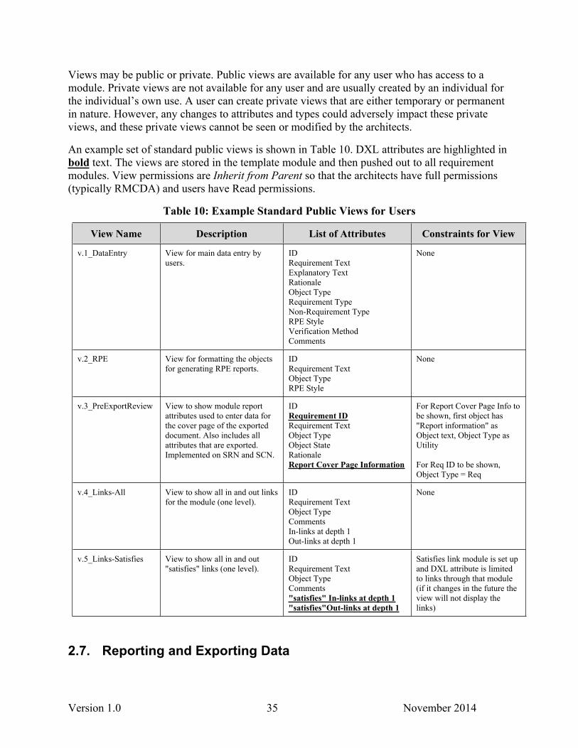
Views may be public or private. Public views are available for any user who has access to a module. Private views are not available for any user and are usually created by an individual for the individual’s own use. A user can create private views that are either temporary or permanent in nature. However, any changes to attributes and types could adversely impact these private views, and these private views cannot be seen or modified by the architects.
An example set of standard public views is shown in Table 10. DXL attributes are highlighted in bold text. The views are stored in the template module and then pushed out to all requirement modules. View permissions are Inherit from Parent so that the architects have full permissions (typically RMCDA) and users have Read permissions.
Table 10: Example Standard Public Views for Users
View Name Description List of Attributes Constraints for View
v.1_DataEntry View for main data entry by users.
IDRequirement TextExplanatory TextRationaleObject TypeRequirement TypeNon-Requirement TypeRPE StyleVerification MethodComments
None
v.2_RPE View for formatting the objects for generating RPE reports.
IDRequirement TextObject TypeRPE Style
None
v.3_PreExportReview View to show module report attributes used to enter data for the cover page of the exported document. Also includes all attributes that are exported. Implemented on SRN and SCN.
IDRequirement IDRequirement TextObject TypeObject StateRationaleReport Cover Page Information
For Report Cover Page Info to be shown, first object has "Report information" as Object text, Object Type as Utility
For Req ID to be shown, Object Type = Req
v.4_Links-All View to show all in and out links for the module (one level).
IDRequirement TextObject TypeCommentsIn-links at depth 1Out-links at depth 1
None
v.5_Links-Satisfies View to show all in and out "satisfies" links (one level).
IDRequirement TextObject TypeComments"satisfies" In-links at depth 1"satisfies"Out-links at depth 1
Satisfies link module is set up and DXL attribute is limited to links through that module (if it changes in the future the view will not display the links)
2.7. Reporting and Exporting Data
Version 1.0 36 November 2014
2.7.1. Reporting Options
There are several options for generating reports in DOORS. Reports include requirement documents, traceability reports, and metrics on DOORS data. Reports can be generated from a subset of information (filtered and sorted data), as well as from multiple modules. Identifying the type of reporting needed or desired at the beginning of the project is recommended as it can affect the information architecture and format of the data in DOORS.
While the DOORS built-in reporting capabilities are appropriate for quickly exporting the data into a draft or sharable format, and the CD Export script is appropriate for engineering specification reports, we recommend using Rational Publishing Engine (RPE) for generating other reports as it lends the most flexibility.
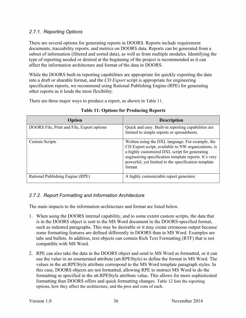
There are three major ways to produce a report, as shown in Table 11.
Table 11: Options for Producing Reports
Option DescriptionDOORS File, Print and File, Export options Quick and easy. Built-in reporting capabilities are
limited to simple reports or spreadsheets.
Custom Scripts Written using the DXL language. For example, the CD Export script, available to NW organizations, is a highly customized DXL script for generating engineering specification template reports. It’s very powerful, yet limited to the specification template format.
Rational Publishing Engine (RPE) A highly customizable report generator.
2.7.2. Report Formatting and Information Architecture
The main impacts to the information architecture and format are listed below.
1. When using the DOORS internal capability, and to some extent custom scripts, the data that is in the DOORS object is sent to the MS Word document in the DOORS-specified format, such as indented paragraphs. This may be desirable or it may create erroneous output because some formatting features are defined differently in DOORS than in MS Word. Examples are tabs and bullets. In addition, text objects can contain Rich Text Formatting (RTF) that is not compatible with MS Word.
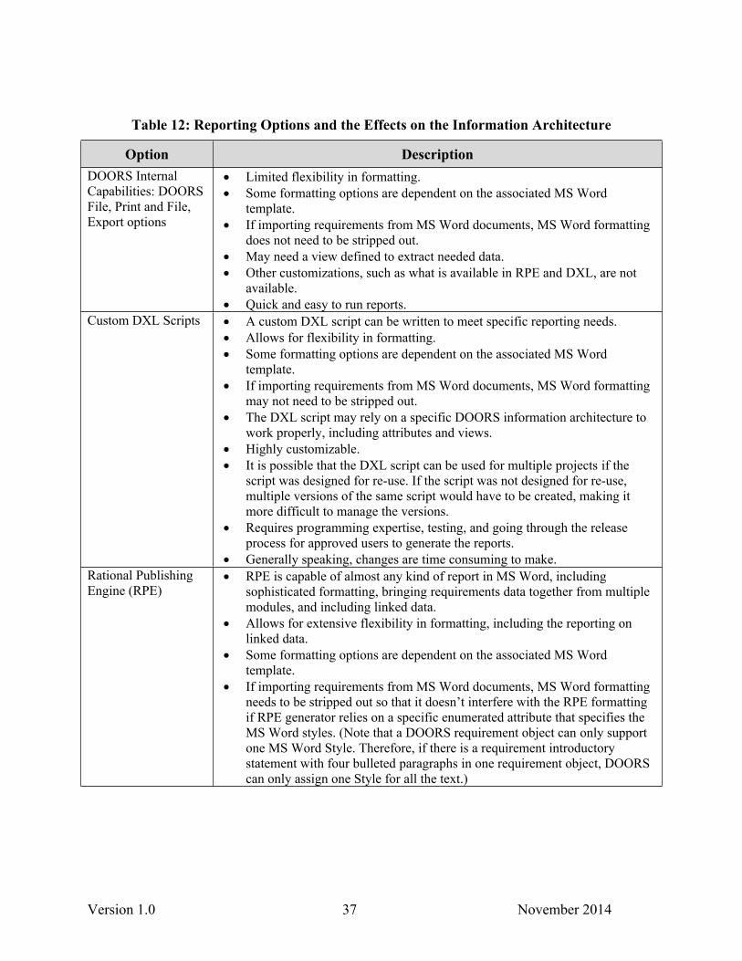
2. RPE can also take the data in the DOORS object and send to MS Word as formatted, or it can use the value in an enumerated attribute (att.RPEStyle) to define the format in MS Word. The values in the att.RPEStyle attribute correspond to the MS Word template paragraph styles. In this case, DOORS objects are not formatted, allowing RPE to instruct MS Word to do the formatting as specified in the att.RPEStyle attribute value. This allows for more sophisticated formatting than DOORS offers and quick formatting changes. Table 12 lists the reporting options, how they affect the architecture, and the pros and cons of each.
Version 1.0 37 November 2014
Table 12: Reporting Options and the Effects on the Information Architecture
Option DescriptionDOORS Internal Capabilities: DOORS File, Print and File, Export options
Limited flexibility in formatting. Some formatting options are dependent on the associated MS Word
template. If importing requirements from MS Word documents, MS Word formatting
does not need to be stripped out. May need a view defined to extract needed data. Other customizations, such as what is available in RPE and DXL, are not
available. Quick and easy to run reports.
Custom DXL Scripts A custom DXL script can be written to meet specific reporting needs. Allows for flexibility in formatting. Some formatting options are dependent on the associated MS Word
template. If importing requirements from MS Word documents, MS Word formatting
may not need to be stripped out. The DXL script may rely on a specific DOORS information architecture to
work properly, including attributes and views. Highly customizable. It is possible that the DXL script can be used for multiple projects if the
script was designed for re-use. If the script was not designed for re-use, multiple versions of the same script would have to be created, making it more difficult to manage the versions.
Requires programming expertise, testing, and going through the release process for approved users to generate the reports.
Generally speaking, changes are time consuming to make. Rational Publishing Engine (RPE)
RPE is capable of almost any kind of report in MS Word, including sophisticated formatting, bringing requirements data together from multiple modules, and including linked data.
Allows for extensive flexibility in formatting, including the reporting on linked data.
Some formatting options are dependent on the associated MS Word template.
If importing requirements from MS Word documents, MS Word formatting needs to be stripped out so that it doesn’t interfere with the RPE formatting if RPE generator relies on a specific enumerated attribute that specifies the MS Word styles. (Note that a DOORS requirement object can only support one MS Word Style. Therefore, if there is a requirement introductory statement with four bulleted paragraphs in one requirement object, DOORS can only assign one Style for all the text.)

Version 1.0 39 November 2014
3. KEY INFORMATION ARCHITECTURAL CONCEPTS
3.1. Defining the DOORS Requirements Management Project
3.1.1. DOORS Project Roles and Responsibilities
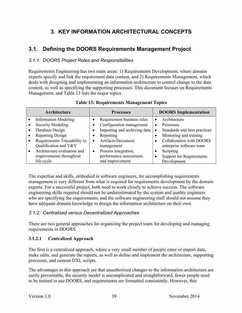
Requirements Engineering has two main areas: 1) Requirements Development, where domain experts specify and link the requirement data content, and 2) Requirements Management, which deals with designing and implementing an information architecture to control change to the data content, as well as specifying the supporting processes. This document focuses on Requirements Management, and Table 13 lists the major topics.
Table 13: Requirements Management Topics
Architecture Processes DOORS Implementation Information Modeling Security Modeling Database Design Reporting Design Requirements Traceability to
Qualification and V&V Architecture evaluation and
improvements throughout life cycle
Requirement business rules Configuration management Importing and archiving data Reporting Artifacts/Document
management Process integration,
performance assessment, and improvement
Architecture Processes Standards and best practices Mentoring and training Collaboration with DOORS
enterprise software team Scripting Support for Requirements
Development
The expertise and skills, embodied in software engineers, for accomplishing requirements management is very different from what is required for requirements development by the domain experts. For a successful project, both need to work closely to achieve success. The software engineering skills required should not be underestimated by the system and quality engineers who are specifying the requirements, and the software engineering staff should not assume they have adequate domain knowledge to design the information architecture on their own.
3.1.2. Centralized versus Decentralized Approaches
There are two general approaches for organizing the project team for developing and managing requirements in DOORS.
3.1.2.1 Centralized Approach
The first is a centralized approach, where a very small number of people enter or import data, make edits, and generate the reports, as well as define and implement the architecture, supporting processes, and custom DXL scripts.
The advantages to this approach are that unauthorized changes to the information architecture are easily preventable, the security model is uncomplicated and straightforward, fewer people need to be trained to use DOORS, and requirements are formatted consistently. However, this
Version 1.0 40 November 2014
approach can also be a bottleneck when a quick turnaround is required to meet a deadline or when DOORS experts are unavailable.
As the domain experts are probably unfamiliar with using the DOORS tool to its full potential, they most likely create the requirements in MS Word or Excel for later import into DOORS. Word and Excel allows great flexibility in formatting the information, and usually authors take advantage of that flexibility. However, that sophisticated formatting does not always import into DOORS the way you would expect it to so that you can generate reports to achieve the original MS Word formatting. Because MS Word allows flexibility in formatting, and that formatting can imply relationships amongst the information, the MS Word structure cannot always directly translate to a DOORS information architecture. The implied formatting in MS Word may not be understood by the non-domain experts when they import the requirements into DOORS. In addition, DOORS has limited formatting options compared to MS Word.
3.1.2.2 Decentralized Approach
The second approach is decentralized, where a large number of people playing various requirement development roles in the project create or import data, make edits, link requirements, and generate the reports. There are also staff members who define, implement, and manage the information architecture.
The advantage to this approach is that the domain experts who specify the requirements are doing the editing and generating reports, making for a more efficient approach, especially when a deadline approaches. However, this approach requires more end user training and effective communication, and potentially leadership oversight, to ensure that everyone is adhering to the implemented architecture, as well as following the established business rules and processes. If domain experts do not respect the established information architecture and processes, the information architecture will soon become a quagmire of duplicate attributes, long lists of views, and unspecified linking.
3.1.3. Requirements Management Project Scope
Because DOORS is a requirements management tool, it might seem obvious that the tool is designed to manage requirements data. However, DOORS is first and foremost a database, and you can manage any structured data in DOORS; not just requirements data. Test results, test plan documents, roles and responsibilities, business rules, records of decision for changing requirements, files, and other information can all be managed in DOORS.
The larger the project, the greater the potential that DOORS is just one of many tools used by a project team; and the capabilities of several tools may overlap. Looking at the full suite of tools to manage data for your project, the main scoping questions to consider are listed below.
What information is appropriate to manage in DOORS versus another tool?
What is the impact to the project if some information is not managed in DOORS?
What set of information can reliably be kept up to date in DOORS so that it is usable information?
Version 1.0 41 November 2014
Are adequate funding and the right type of personnel resources available throughout the project lifecycle to support and maintain the information?
3.1.4. Tool Functionality
While most tools have numerous functionality areas, selecting a tool that affords significant flexibility in designing the optimal information architecture for a specific project is critical for managing and utilizing the data throughout the project’s life. Managing requirements for a full-blown requirements management effort demands a well-designed information architecture supported by a tool that allows flexibility in designing that architecture, as it does for a project with limited requirements management needs.
Our experience with any requirements management information architecture in an automated tool is that once people start using the capability and seeing its potential, people will demand more functionality. The information architecture must be able to support this without a major redesign. Thus, our recommendation is to design an information architecture that will meet the needs of the project at the beginning of the project as well as for the anticipated needs throughout the life of the project. The design can be implemented in stages as the project matures. An example would be to implement the satisfies trace and plan for the verifies trace.
3.1.5. Integration with Data in Other Tools
Often DOORS data needs to integrate with data captured in other tools, such as IBM Rhapsody for model based systems engineering or National Instruments LabView and Test Stand for testing activities. The DOORS architecture, as well as supporting processes, may need to be designed to potentially accommodate integrating with data captured in other tools or repositories.
Generally speaking, it is desirable to store the information closest to where it was created. For example, store requirements data in DOORS; test data and results in LabView. However, an integration point needs to be defined as LabView may need to import requirements from DOORS, and DOORS reports may need the final pass/fail test results from LabView for reporting. Understanding the entire tool suite, the process to import or export information including updates, and the integration points will help determine what data should be captured and managed in DOORS.
3.1.6. Resources to Support the Project Scope
While it might be considered a “good idea” to manage an extensive set of requirements and descriptive information in DOORS, the technical and administrative burden of managing that information throughout the project life requires adequate funding and available personnel with the right skill sets. The DOORS architect can design an information architecture with an extensive set of requirements and descriptive information, but only implement a subset of the information architecture to meet the project’s current needs. This is where the architect’s years of experience with a wide range of projects can provide invaluable guidance to the project’s management.
Version 1.0 42 November 2014
Resources will affect the project scope as all DOORS information needs to be managed now and throughout the life of the project to instill confidence in those using the data to make decisions. If a full-blown set of requirements information can’t be managed adequately by people with the right skill sets, then pare it down to a smaller set of high-value requirements information that can be managed well in DOORS.
Here is a list of technical resources needed for requirements engineering using DOORS:
Domain expertise for developing and linking requirements for traceability
Requirements development technical writing skills for ensuring requirements are well written
Database design expertise for creating a sound information architecture
Tool expertise for maintaining and managing the information architecture and the data
Configuration management expertise for developing and implementing processes such as releasing reports, baselining, archiving, requirement change management, and version control for DXL scripts
RPE programming and reporting skills
DXL programming skills
System and tool administration, performed by the Lifecycle Management Solutions Organization, currently Org. 9512, for the CEE DOORS installation
3.2 Interacting with the DOORS Data
The data you need to pull out of DOORS, such as requirement documents and traceability reports, will help determine what information you store in DOORS and how the information is related. How people will interact with and manipulate the data will determine how to structure the information in folders and modules, as well as how to describe and view the data.
3.2.1. Creating Requirements
The ideal way for data to be entered into DOORS is to directly create the requirements and related information in the DOORS modules, which are created from a template containing the standard attributes, types, and views. The template may also contain standard headings and subheadings to organize the data in modules.
It is important to establish a set of business rules for creating requirements and associated data. Business rules establish standards for consistency in developing, linking, and exporting the requirement information.
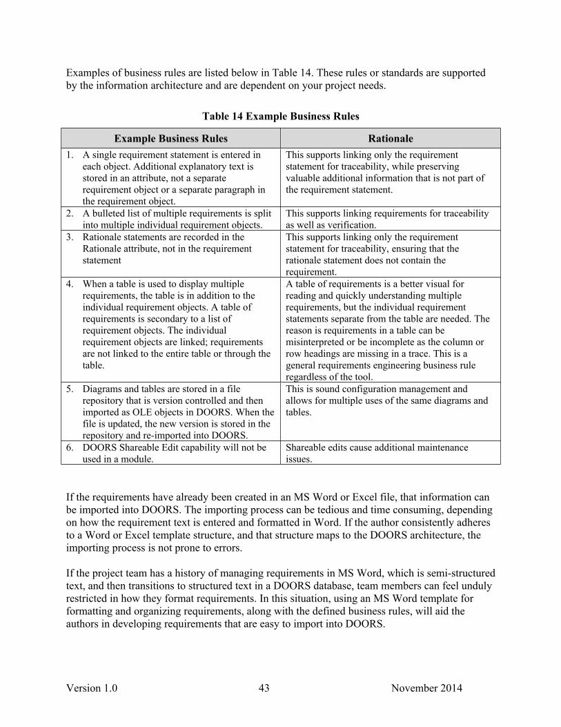
Version 1.0 43 November 2014
Examples of business rules are listed below in Table 14. These rules or standards are supported by the information architecture and are dependent on your project needs.
Table 14 Example Business Rules
Example Business Rules Rationale1. A single requirement statement is entered in
each object. Additional explanatory text is stored in an attribute, not a separate requirement object or a separate paragraph in the requirement object.
This supports linking only the requirement statement for traceability, while preserving valuable additional information that is not part of the requirement statement.
2. A bulleted list of multiple requirements is split into multiple individual requirement objects.
This supports linking requirements for traceability as well as verification.
3. Rationale statements are recorded in the Rationale attribute, not in the requirement statement
This supports linking only the requirement statement for traceability, ensuring that the rationale statement does not contain the requirement.
4. When a table is used to display multiple requirements, the table is in addition to the individual requirement objects. A table of requirements is secondary to a list of requirement objects. The individual requirement objects are linked; requirements are not linked to the entire table or through the table.
A table of requirements is a better visual for reading and quickly understanding multiple requirements, but the individual requirement statements separate from the table are needed. The reason is requirements in a table can be misinterpreted or be incomplete as the column or row headings are missing in a trace. This is a general requirements engineering business rule regardless of the tool.
5. Diagrams and tables are stored in a file repository that is version controlled and then imported as OLE objects in DOORS. When the file is updated, the new version is stored in the repository and re-imported into DOORS.
This is sound configuration management and allows for multiple uses of the same diagrams and tables.
6. DOORS Shareable Edit capability will not be used in a module.
Shareable edits cause additional maintenance issues.
If the requirements have already been created in an MS Word or Excel file, that information can be imported into DOORS. The importing process can be tedious and time consuming, depending on how the requirement text is entered and formatted in Word. If the author consistently adheres to a Word or Excel template structure, and that structure maps to the DOORS architecture, the importing process is not prone to errors.
If the project team has a history of managing requirements in MS Word, which is semi-structured text, and then transitions to structured text in a DOORS database, team members can feel unduly restricted in how they format requirements. In this situation, using an MS Word template for formatting and organizing requirements, along with the defined business rules, will aid the authors in developing requirements that are easy to import into DOORS.
Version 1.0 44 November 2014
3.2.2. Updating, Viewing, and Linking Requirements
It is important to understand how your project team wants to work with DOORS data in different situations, such as design reviews, Fagan inspections, or updating information. The various roles, including engineers, quality staff, technical writers, or managers, will interact with DOORS differently. Several standard views can be created to support these various needs.
Filtering is a very powerful feature in DOORS, and you can filter on attributes, links, and columns. Filters in views can display requirements that were modified since a specific date, have text entered in the red-lined column, or that have no links. The DOORS redlining feature preserves the original requirement text while changes are displayed in another column.
While the DOORS display options are not ideal for viewing and updating the information on a large screen in a team setting, we recommend that you not export the DOORS data to an Excel or Word document to view the information, make changes, and then re-enter or re-import those changes back into DOORS at a later date. This process invites mistakes in data entry and the possibility that conflicting changes are made to the same requirements in the duplicate versions of the data. These same risks exist if you copy a module and make tentative changes to requirements for later updating in the “real” module.
Once the requirements are fairly stable, meaning that few changes are made to the requirements, linking requirements can begin. Linking is an excellent means for verifying requirements and identifying gaps. A generalized linking model illustrates object relationships by displaying the link, source, and target modules. It clarifies the information architecture for traceability so that people understand what is allowable when making links.
A formal change management process at the requirement object level is needed for at least medium- or large-sized projects when several staff members are linking requirements. This process, hopefully automated, needs to be defined well in advance of the linking effort so that everyone knows what to do when mistakes, inconsistencies, or gaps are discovered. If team members do not follow the process and the security model allows people to make changes to any requirement, chaos will follow and it will be extremely difficult to undo changes. If this situation occurs, you may have to submit a ticket to the system administrators to retrieve old versions of one or more modules so that linking can be redone.
3.2.3. Reporting
A good place to start understanding how to architect the data in DOORS is to specify the reports that will be generated. Detailed mockup reports created in MS Word illustrate the content and formatting requirements. Any MS Word or Excel templates used for generating reporting should be identified and incorporated into the mockups.
The reporting capabilities built into DOORS are limited, even if you enhance the exporting with DXL scripts. The reason is DOORS is a database tool and not a report generation tool. Thus, we recommend using Rational Publishing Engine (RPE) for generating any reports from DOORS beyond the very basic ones. RPE is a powerful, flexible report generation tool that allows for
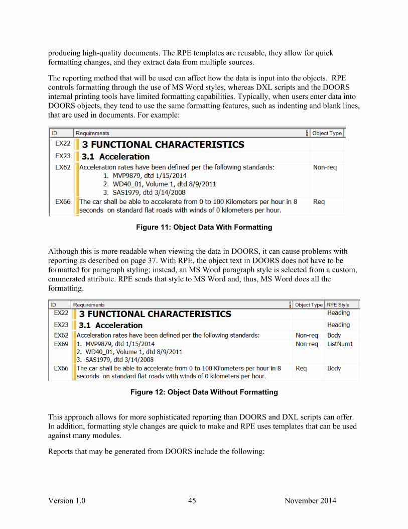
Version 1.0 45 November 2014
producing high-quality documents. The RPE templates are reusable, they allow for quick formatting changes, and they extract data from multiple sources.
The reporting method that will be used can affect how the data is input into the objects. RPE controls formatting through the use of MS Word styles, whereas DXL scripts and the DOORS internal printing tools have limited formatting capabilities. Typically, when users enter data into DOORS objects, they tend to use the same formatting features, such as indenting and blank lines, that are used in documents. For example:
Figure 11: Object Data With Formatting
Although this is more readable when viewing the data in DOORS, it can cause problems with reporting as described on page 37. With RPE, the object text in DOORS does not have to be formatted for paragraph styling; instead, an MS Word paragraph style is selected from a custom, enumerated attribute. RPE sends that style to MS Word and, thus, MS Word does all the formatting.
Figure 12: Object Data Without Formatting
This approach allows for more sophisticated reporting than DOORS and DXL scripts can offer. In addition, formatting style changes are quick to make and RPE uses templates that can be used against many modules.
Reports that may be generated from DOORS include the following:
Version 1.0 46 November 2014
Formal reports for customers. If there are multiple customers with varying reporting requirements on the same data, these differences will need to be accounted for in the information architecture and/or in RPE.
Internal verification, inspection, or review. These reports could be used by individuals or in a team setting.
Traceability. These reports support gap analysis and completeness reviews. The trace reports can be one or multiple levels.
Comparisons. Identifying changes in the current version with a baselined version.
Metrics. Metric reports could include such things as identifying how many requirement objects have changed since the last baseline or how many requirements have not yet been linked.
3.3. Modeling the DOORS Information
3.3.1 Information Architecture Concepts
Communicating with DOORS users on how they use requirements information, such as for filtering and sorting, and how they want to interact with the tool to accomplish various tasks will help define the information architecture from data and usability perspectives. A DOORS project will also need information to administer and manage the DOORS project, such as importing data, as well as a playground area where people can learn DOORS functionalities. Diagrams, pictures, and other graphics can be managed in a separate version control system, such as TeamForgeSVN, and imported into the DOORS modules.
We document as much of the information architecture in DOORS modules as possible, either by running scripts to populate the module, or by manual data entry. This information is augmented by an information architecture document that is version controlled and contains diagrams for illustrating concepts.
After designing the folder structure, all of the information architecture elements must eventually be analyzed and tested as a whole. This includes how the information is segmented into modules, the required traces, and the security model. If the information architecture is difficult to document, explain to others, or requires some “trickery” to implement, then the information architecture will be difficult to support over the life of the project and a redesign is highly recommended.
3.3.2 Module Architecture Approaches
There are three main approaches to designing the modules in the information architecture. Whatever approach you use, which could be a hybrid approach, the module structure is based on a thorough analysis of the requirements information to be managed in DOORS, including any existing requirements documents that will be imported. The composition of the project and the existing data will determine what approach to take.
Version 1.0 47 November 2014
3.3.2.1. Data-Driven Architecture
In a data-driven architecture, the data use and access needs drive how the modules are set up for managing the requirements. This is the ideal approach, as there are no existing constraints on how you organize the information into modules, so you don’t have to make concessions on the design. A data modeling methodology, such as ORM described on page 11, and concrete examples will aid the architect in segmenting the information into modules that support creating and editing requirements, tracing, and reporting.
The first step is to find commonalities amongst the information in order to create a folder hierarchy for traceability. One example would be system, components, and subcomponents. Another would be customer requirements, Sandia policies, Sandia processes. The next step is to divide the common information into categories, which translates to individual modules. Then test your structure to ensure that people can edit the modules without conflicts with other users and that your tracing needs are met.
3.3.2.2. Document-Driven Architecture
In a document-driven architecture, there is a one-to-one mapping between a DOORS requirement/design module and the document to be generated. The ideal situation is if the document set is designed taking into account the DOORS linking model so that the traceability needs can be easily met. This architecture also tends to be better for having multiple editors for content and linking because a module can be opened for editing (Exclusive Edit2) by only one person at any one time, and with this architecture only a subset of the requirements is usually stored in any one module.
On the other hand, a drawback of this information architecture is that requirements are distributed among several modules in DOORS which makes it difficult if engineers want to view requirements from other modules or include those requirements in the report generated from the original module. This architecture does not directly support that ability since copying requirements from one module to another module is never recommended as it will create conflicting, duplicate sets of requirements. We can use the RPE reporting tool to include requirements from multiple modules into a single report. DXL also can be used to include requirements from multiple modules into a single view, but a DXL solution can be more complicated than an RPE solution and may impact performance within DOORS.
3.3.2.3. Level-Driven Architecture
In this model, all of the requirements that are in a particular level in the satisfies trace are stored in a single module. A components module, for example, would contain all of the project’s component requirements, which could be thousands of requirement objects. Views with filters are created to display the requirements for export to generate each document report. Pictures, tables, and diagrams are stored in a single module and linked to the requirements module. There is a separate module for document front matter and another for document back matter.
2 DOORS does have a Shareable Edits feature that allows for multiple editors in a single module; however, as indicated earlier in this document, this feature can cause maintenance issues, and we do not recommend it.
Version 1.0 48 November 2014
This information architecture works best for smaller projects, where there is a small number of requirements and only one or two people editing and linking requirements. Because a diagram is potentially used in more than one document, it is unnecessary to store multiple copies of the diagram in the modules. Instead, a link is made from an object in the requirements module to an object in the diagrams module.
The linking model may be more complex than in a document-driven architecture. Linking within a single module is technically possible, but discouraged because of the complexity; therefore, the linking model needs to be designed carefully to ensure that all traceability needed is technically feasible in DOORS before the information architecture is implemented. Views with filters are thoroughly tested, and checks are made on all of the attribute values to ensure that the correct set of data is displayed for a complete and accurate export to a document.
3.3.3. SCN vs. SRN DOORS
If a portion of a project’s requirement information is classified and traceability reports will be generated, then we recommend that all of the requirement information be stored on the Sandia Classified Network (SCN). Linking requirements between the Sandia Restricted Network (SRN) and the SCN is not technically feasible. In addition, managing the requirements in two databases on two networks can be overly complicated, time consuming, and error prone. Most importantly of all, the aggregation of requirements information on the SRN could result in a security incident by producing classified information. If an unclassified report is generated from SCN DOORS, it can be transferred to the SRN using Sandia’s downshifting process. If it is decided that requirements information will be kept on both the SRN and SCN, then a DOORS synchronization process is available to sync DOORS information between the two repositories.
If both the SCN and SRN DOORS are used to store separate sets of requirements that are not linked between the SCN and the SRN, a derivative classifier needs to be involved in the decision, as well as consumers of the information, to determine what their needs are for editing, reading, tracing, and generating reports. The architectures should be the same for both SRN and SCN DOORS projects for optimal maintenance and management, with the possible exception of the folder structure. Detailed processes should be developed and implemented to manage the two repositories of requirements, including auditing processes.
We have had success creating and editing requirements on the SRN and then using the Reliable Automated File Transfer Service (RAFTS) to transfer modules to the SCN that have read-only access. See SCN RAFTS for more information. However, this precludes any linking on the SCN, as you need editing permissions to link.
Our unclassified information architecture models, scripts, and other DOORS functionality are developed on the SRN and managed in either DOORS or the TeamForge SVN repository. The information is then released to the SRN and/or SCN using a formal release process. If the script or model is classified, it is created and maintained only on the SCN.
An SCN DOORS project may need to link to information used by several projects that are stored in another SRN DOORS project, such as a subset of the D&P Manual or the Technical Business Practices in the Nuclear Weapons program. One option for addressing this situation is to RAFT the modules from the SRN DOORS project, i.e., the gold copy of the information, to the SCN
Version 1.0 49 November 2014
DOORS project. Then link from the requirement object to the object in the reference document. A process to keep the project information in sync with the gold copy data needs to be developed. A second option is to create a Document Reference module on the SCN and list all of the documents so they are uniquely identified. Then link from the requirement object to the document object. This relationship is a coarser granularity than the first option but requires less synchronization oversight.
3.3.4. Describing and Viewing Data Content
A template module containing standard attributes, types, and views can be used to create all requirements modules or administrative modules, which ensures that the modules contain the same attributes, types, and views. This is important so that you are not “managing by exception” and that all of the attributes and types exist in every module to execute DXL scripts or run RPE reports. If an attribute or view is not applicable in a module, then the users just ignore it. We recommend maintaining one template for the entire project and using naming standards to indicate standard vs. non-standard attributes or views, or administrative vs. technical attributes.
The ReqMAPS team has a global template module that we use for all of the DOORS projects that we support. If there are project-specific needs, we create a project-specific template, based on the global template. The global template is managed and maintained on the SRN and RAFTed to the SCN if needed.
The ReqMAPS team has developed DXL auditing scripts to identify any attributes, types, and views in DOORS that are not in the template module. This provides a way to keep the information architecture intact. If new or modified attributes, types, and views are discovered during the audits, the architects can talk with the staff that made the changes to find out their reasons for the changes. Typically the users didn’t understand the architecture or their needs are not being met. The changes can be analyzed and potentially implemented.
3.4. Security Model
Every DOORS project will have a different security model to control access to the project, folders, and modules, as well as controlling permissions for reading, creating, modifying, deleting, and administering information. The security model balances risk and administrative burden. The first questions to ask when defining a security model are the following:
What are the risks if everyone on the project has full permissions on all of the information?
Can the project adequately manage those risks?
Can we afford the administrative burden to manage a stringent security model, both in dollars and staff?
Can we ensure that staff will have access to all the information they need to perform their work in a timely manner?
Identifying the project roles, the tasks each role performs, and how each role interacts with the DOORS data will help determine the security model. In addition, some information is inherently
Version 1.0 50 November 2014
more sensitive and may require more stringent controls. There may be many people performing work in multiple roles on a larger project, and it is critical for each person to understand and respect the boundaries of the various roles. If there is a history of unauthorized edits made to information by a person not in a designated role, chaos could ensue and trust relationships broken. This may force a redesign of the security model.
Modules and all of the information they contain should inherit the DOORS permissions for read, create, modify, delete, and administer from the parent folder. Inheritance can be broken at the project or folder level, as that is relatively easy to manage. Using metagroups to control access to projects, folders, and modules is required for the CEE and Org. 5700 DOORS installations at Sandia, even if there is just one metagroup controlling access to the entire project. All metagroups should have at least Read access at the project level. This ensures proper inheritance as well as migrating data with the correct metagroups to a different DOORS installation or possibly a different requirements tool.
If the security model seems overly complex, such as controlling access at the attribute level for individual requirement objects, then you need to reanalyze the linking, folder, module, and security models. Most likely you are trying to use attributes when linking would be more appropriate.
3.5. Supporting the Requirements Engineering Process
3.5.1. Data Content and Information Architecture Change Management
Change management processes should be defined for both the data content and the DOORS architecture.
3.5.1.1. Data Content Change Management
While requirements change management functionality is included in the DOORS application, we consider the functionality to be woefully inadequate for comprehensive requirements change management. Note that the change management is at the requirement object level, which is not the same as using a version control system to manage the reports generated from DOORS. Change management must be conducted at both levels.
A manual process for change management can be implemented, but there is no way to enforce that process within DOORS, such as with automated tools. IBM’s Rational Team Concert (RTC) tool for requirements change management integrates with the DOORS application and provides comprehensive requirements change management functionality. The RTC tool requires a learning curve to design and implement the change management workflows, and the software tool needs to be stood up and maintained. However, for medium- to large-sized or complex projects, we recommend standing up the tool and planning the change workflows as it is less costly than reacting to fix problems when unauthorized, unapproved, or non-communicated changes are made to requirements.
3.5.1.2. Architecture Change Management
Version 1.0 51 November 2014
All changes to the information architecture must follow an information architecture change management process. This encompasses changes to the security model, attributes, types, views, modules, and folder structure. Proposed changes should be analyzed, tested, and documented before implementation. Changes to the information architecture can be captured as they occur by updating a module specifically for this purpose. We have used a module called “ArchitectureChangeLog.lup” to record details of the information architecture change, including description, rationale, implementer, and implementation date.
The following is a change management process that can be implemented manually:
1. Submit proposed change, using a tracking system such as a Tracker in TeamForge.
2. Discuss the proposed change with the appropriate staff and management to understand the proposed change, technical implications and risk, options for implementing, resources required, and schedule. Decide whether the change should be implemented and if so, if there are any adjustments to the original proposed change. Document all of this in the tracking system.
3. If approved, implement the proposed changes in your DOORS quality environment. The quality environment could be DOORS on the quality server or a separate project you have created in DOORS to use as the quality environment, which is protected with more stringent access controls.
4. Define and conduct testing, following your testing processes. Special attention is paid to how the change would affect DXL scripts, views, filtering, traceability, and reporting, as well as data exported to other applications such as Rhapsody.
5. Review the implementation in the DOORS quality environment with the appropriate staff and management. If needed, modifications are made, tested and reviewed.
6. Document testing and reviewing results in the tracking system.
7. Obtain approval to install the change in the DOORS production environment.
8. Notify users about any down time while installing the information architecture change in the DOORS production environment, along with the description of the changes.
9. Make the proposed changes in the DOORS production environment.
10. Update the documentation and communicate details of the information architecture change. The project information architecture document or modules are also updated, if needed.
11. Update and close the item in the tracking system, communicate the changes to the users, and publish the updated documentation.
3.5.2. Baselining
A baseline is a read-only version of a module that captures a point in time of the module. We recommend using two types of baselines: formal and checkpoint. A formal (FML) baseline
Version 1.0 52 November 2014
should be used to capture a formal snapshot of requirement configuration items that represent the requirements and associated data at a specific point in time which represents a significant project milestone. Once requirements have been formally baselined, a change management process should be followed to make subsequent changes to the requirements.
There are other points in time during the requirement lifecycle when a snapshot of requirement configuration items may be taken, but the snapshot is not a formal baseline requiring change management processes to be enacted. To differentiate these requirement snapshots from the formal baseline snapshots, we refer to these other snapshots as checkpoints (CKP) or checkpoint baselines.
3.5.2.1. Baselining Process
The process of creating either a formal baseline or a checkpoint is called baselining, and both formal baselines and checkpoints are referred to generically as baselines. The DOORS tool has a baseline capability, and the terminology used in the tool is baseline. When using the baseline terminology with respect to the DOORS capability, it includes actions taken within DOORS and the result of those actions within DOORS.
Every baseline is assigned a baseline version as part of the DOORS baselining steps. The standard format for a baseline version is
<major number>.<minor number> .<number>[_<brief description>]_<baseline type>
The major and minor numbers are required by DOORS whenever a DOORS baseline is created. They also are controlled by DOORS so that only certain options are allowed. The rest of the baseline version is an optional suffix for a DOORS baseline and may contain unique identifying information that makes it easier to understand the type of baseline (FML or CKP) and the purpose.
An example baseline version for a Formal baseline is 1.1.0_milestoneFY14M2_FML where
1 is the major number
0 is the minor number
0 is an identifying number
“milestoneFY14M2” indicates a capture for a project milestone
FML indicates it is a formal baseline and the contents should be placed under change control
An example of a baseline version for a Checkpoint baseline is 2.2.0_preFagan_CKP where
2 is the major number
2 is the minor number indicating the second baseline of the contents
0 is an identifying number
“preFagan” indicates a capture prior to a Fagan inspection of the versioned contents
Version 1.0 53 November 2014
“CKP” indicates it is a checkpoint baseline and the contents are not placed under change control
A detailed description of the steps needed for baselining requirements in DOORS can be found in the DOORS Requirements Baselining Procedures document on Sandia’s DOORS SharePoint site at https://sharepoint.sandia.gov/sites/DOORS/SitePages/Home.aspx?RootFolder=%2Fsites%2FDOORS%2FDOORS%20User%20Documentation%2FHow%20To%27s. A DOORS baseline does not include views and external DXL code, that is DXL code kept on the file system and not stored in a DXL attribute in DOORS. The referenced baselining procedures includes instructions and suggestions for capturing views and external DXL.
3.5.2.2. Baseline Sets
A DOORS baseline is a snapshot of a single module at a particular point in time. Requirements information may exist in multiple modules in DOORS, so every module that contains information relevant to the requirements needs to be included when baselining requirements. If you need to capture information in more than one module or capture relationships (links) between the modules, then a DOORS baseline set should be used.
Per the DOORS manual “[a] baseline set is a group of baselines that you want to treat as a single unit for project planning and management purposes.” For our purposes, the key reason for using baseline sets is to baseline links. If a baseline set is not used, then links will point to the current version of the object in the target module regardless of whether the target module has been baselined. This means that if the content of the object linked to in the target module changes, then we will have lost what was being linked to at the time of the baseline. Figure 13 illustrates the impact of baseline sets on linked information and baselines.
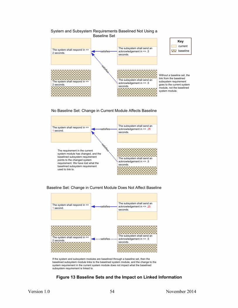
Version 1.0 54 November 2014
Baseline Set: Change in Current Module Does Not Affect Baseline
satisfies
The subsystem shall send an acknowledgement in <= .5 seconds.
satisfies
The system shall respond in <= 1 second.
The subsystem shall send an acknowledgement in <= .25 seconds.
If the system and subsystem modules are baselined through a baseline set, then the baselined subsystem module links to the baselined system module, and the change to the system requirement in the current system module does not impact what the baselined subsystem requirement is linked to.
KeycurrentbaselinesatisfiesThe system shall respond in <=
2 seconds.
The subsystem shall send an acknowledgement in <= .5 seconds.
System and Subsystem Requirements Baselined Not Using a Baseline Set
The subsystem shall send an acknowledgement in <= .5 seconds.
satisfies
No Baseline Set: Change in Current Module Affects Baseline
satisfiesThe system shall respond in <= 1 second.
The subsystem shall send an acknowledgement in <= .5 seconds.
satisfiesThe requirement in the current system module has changed, and the baselined subsystem requirement points to the changed system requirement. We have lost what the baselined subsystem requirement used to link to.
The subsystem shall send an acknowledgement in <= .25 seconds.
The system shall respond in <= 2 seconds.
The system shall respond in <= 2 seconds.
Without a baseline set, the link from the baselined subsystem requirement goes to the current system module, not the baselined system module.
Figure 13 Baseline Sets and the Impact on Linked Information
Version 1.0 55 November 2014
So, the key in determining whether a baseline set is needed is determining whether the linking needs to be preserved.
The following criteria can be used in determining what should be included in the baseline set:
1. The main requirements module hierarchy should be captured.
2. Any module that is a target or source module of a linkset for the modules in the main requirements hierarchy may be included in the baseline. If the information from a target or source module is providing significant data in the main requirements module (e.g. through a DXL attribute or layout DXL column created through the analysis wizard), then that target or source module should be included in the baseline.
We also recommend an additional means of saving links in a baseline or baseline set by using a utility that is part of the DOORS add-on PS Toolbox. The utility in the PS Toolbox is called “Save links as an Attribute.” The utility is run in the source module of a linkset and saves the absolute number of the target object of the link in an attribute of the source module. This provides a secondary capture of the links that is independent of the link module. More information about saving link information using the “Save links as an Attribute” utility can be found in the DOORS Requirements Baselining Procedures document on Sandia’s DOORS SharePoint site at https://sharepoint.sandia.gov/sites/DOORS/SitePages/Home.aspx?RootFolder=%2Fsites%2FDOORS%2FDOORS%20User%20Documentation%2FHow%20To%27s.
3.5.2.3. Locations of Baseline Sets in the DOORS Structure
Baseline sets are maintained within the DOORS folder hierarchy and are part of the folder data. To determine which baseline sets are available, right click on a folder, select Properties, and go to the Baseline Set Definitions tab. To see if an existing Baseline of a module is associated with a baseline set, use the “Baseline -> View” command from the DOORS File menu item within the module.
To capture baseline sets, there are two philosophical views on the best architectural approach. One is to create a specific folder with a meaningful name and do not include formal modules within the folder. The folder should be associated with a particular level in your hierarchy. An example hierarchy with corresponding baseline set folders illustrating this recommendation is shown in Figure 14. The advantage of this architectural setup is that the location of the baseline sets is very clear, especially for users who access the baseline sets infrequently. The disadvantage is a parallel folder structure with empty folders has to be set up and maintained. Furthermore, the empty folders can be confusing for a novice or periodic user who does not understand that the baseline sets are part of the folder data and is looking for an object within the folder. If the architecture change management is weak, then a risk exists of someone deleting the seemingly unused baseline sets folders. If the folder is deleted, the baseline sets are lost. (We know about this risk because it occurred in a very early incarnation of an architecture we had set up.)
The other architectural approach is to define the baseline sets directly on the level folder. With this approach, the parallel folder hierarchy is not necessary; however, the existence and location of baseline sets are not obvious. The risk of the folder with the defined baseline sets being
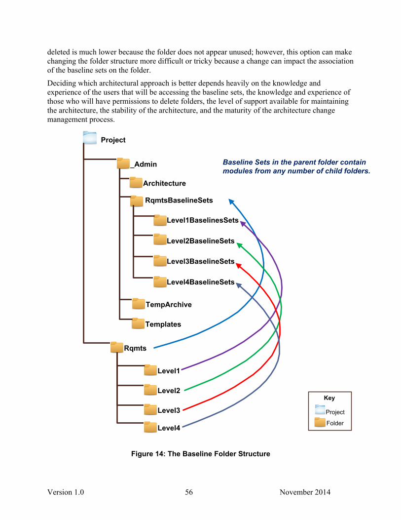
Version 1.0 56 November 2014
deleted is much lower because the folder does not appear unused; however, this option can make changing the folder structure more difficult or tricky because a change can impact the association of the baseline sets on the folder.
Deciding which architectural approach is better depends heavily on the knowledge and experience of the users that will be accessing the baseline sets, the knowledge and experience of those who will have permissions to delete folders, the level of support available for maintaining the architecture, the stability of the architecture, and the maturity of the architecture change management process.
Key
Project
Folder
Project
_Admin
Rqmts
TempArchive
Templates
Architecture
RqmtsBaselineSets
Level1BaselinesSets
Level2BaselineSets
Level3BaselineSets
Level4BaselineSets
Level3
Level4
Level1
Level2
Baseline Sets in the parent folder contain modules from any number of child folders.
Figure 14: The Baseline Folder Structure
Version 1.0 57 November 2014
4. REFERENCES
1. Shelley M. Eaton, Gregory N. Conrad, Identifying and Implementing Patterns in Data Models (U), SAND2003-0804, Sandia National Laboratories, Albuquerque, NM (SRD), March 2003.
Version 1.0 58 November 2014
DISTRIBUTION
1 MS0899 Technical Library 9536 (electronic copy)

Version 1.0 59 November 2014

Version 1.0 60 November 2014