general model ox400 specifications - yokogawa …cdn2.us.yokogawa.com/product_ox400_gs_03.pdf ·...
TRANSCRIPT

GeneralSpecifications
Yokogawa Electric Corporation2-9-32, Nakacho, Musashino-shi, Tokyo, 180-8750 JapanTel.: 81-422-52-5617 Fax.: 81-422-52-6792
Model OX400Low Concentration Zirconia Oxygen Analyzer
GS 11M10B01-01E
GS 11M10B01-01E©Copyright Jun. 2009 1st Edition Jun. 20093rd Edition Mar. 2011
The OX400 is a highly accurate and reliable low-con-centration zirconia oxygen analyzer that is capable of measuring a wide range of concentrations, from 0-10 ppm up to 0-100 vol% O2. This is the latest oxygen analyzer from Yokogawa, and its development was based on the company’s long experience and strong track record with this technology. A proprietary new thin-film deposition technology was used in the zirconia sensor that creates a molecular bond between the zirconia element and the platinum layer. This prevents separation, enables a reduction in sensor size and ensures a high-speed response and long life.The OX400 can be used to control and monitor various semiconductor applications, and to control environ-ment, air leakage into inert gas, and other processes.
Features
Long life and high-speed response• Thanks to the use of Yokogawa’s proprietary new
thin-film deposition technology, the sensor has three times the lifespan of those used in our earlier prod-ucts.
• A cylindrical sensor design facilitates the replacement of measurement gases, thereby helping to assure a high-speed response.
High performance and high reliability• Superior repeatability and linearity even at low oxy-
gen concentrations• Either pump or aspirator sampling can be selected,
depending on the application.• CE, C-tick, cCSAus certification.Built-in functions and a variety of self-diagnosis functions• Comes with multi selector, auto range, partial range,
and pump on/off functions• A variety of self-diagnosis functions are provided that
detect malfunctions such as heater temperature error, temperature sensor burnout, and sensor resistance value error.
Superior maintainability• The sensor can be replaced on-site.• Compact and lightweight for easy installation.
Applications• Oxygen concentration control in semiconductor-relat-
ed diffusion and drying furnaces and in LCD manu-facturing processes
• Oxygen concentration control in solder pot flow and re-flow ovens, and glove boxes used in electronics manufacturing, and in gas production processes
• Oxygen concentration measurements to prevent dust explosions during powder transfer
2
All Rights Reserved. Copyright © 2009, Yokogawa Electric Corporation GS 11M10B01-01E
Standard SpecificationsMeasurement object : Oxygen concentrations in inert
gases containing no flammable gas, silica, corrosive gas, or liquid (including water vapor).
Measurement system: Zirconia systemSampling method
: Pump, aspirator, or no suction device.
Pump and aspirator suction flow rate : Approx. 1.0 l/min.Aspirator suction conditions : Air or N2, supply pressure 65 to 100
kPaG, total discharge flow 10 l/min max. (when gas inlet and outlet are at ambient atmospheric pressure).
Sample gas conditionsFlow rate : 200 ± 25 ml/min (only applies to
sensor).Temperature : 0-50°C (non-condensing).Humidity : Non-condensing.Pressure : 0-300 PaG
Measurement range : 0-10 ppm O2 to 0-100 vol% O2.
Resolution : 0.01 ppm O2.Display : 4 digit LED.
Main display : O2 concentration (auto switching).Sub display : Parameter or alarm/error number
Unit : %, ppm.Output range
Auto : 0-10 ppm, 0-100 ppm, 0-1000 ppm, 0-1%, 0-10%, 0-100% (default) Other: 0-0 ppm, 0-00 ppm, 0-000 ppm, 0-%, 0-0%, is an inte-ger from 2 to 9.
Fixed : Set to 0-10 ppm, 0-100 ppm, 0-1000 ppm, 0-1%, 0-10%, or 0-100%.
Partial : Lower value or upper value of range can be set.
Note :Span (upper value-lower value) is 20% FS or more of above fixed range.
Example: 200-400 ppm when fixed range is 0-1000 ppm , 20-40 ppm when fixed range is 0-100 ppm.
Analog output : 2 outputs, Primary : 4 to 20 mA DC (maximum load
resistance: 550Ω ) Secondary : Select from 0-1, 0-5, 0-10 V DC
(load resistance: 10 kΩ or greater)Contact output : 3 outputs, Error, O2 concentration alarm contact, range
marker contact Multi selector (optional) : Contact output for switching of
measurement flow path, contact output for measurement flow path data. Note: For detailed information, see the external dimensions.
Contact output specifications General : RelayNominal contact capacity: 2 A 30V DC, 2 A 240 V AC
(120 V AC for 100 V power supply) for resistive load
Maximum power: 60 W, 480 VAMaximum voltage: 30 V DC, 264 V AC (132 V AC for
100 V power supply)Maximum current: 2 A DC/AC
Contact input : Voltage-free contact, 1 point : Remote switching for sample gas
suction pump ON/OFFSelf-diagnostics
Error (failure) : Sensor unit error, heater temperature error, temperature sensor disconnection, device temperature error, CPU error, fan stop.
Alarm (warning) : Heater unstable, sensor defect, electromotive force abnormal, asymmetry voltage error, calibration error, sensor resistance error, O2 concentration upper/lower, over range.
Serial communicationComm. signal :RS-232 , one wayBaud rate : 38,400 bpsData (ASCII) : O2 concentration, unit, alarm/error
Calibration methods: (1) 3 point: 10 ppm, 1000 ppm, air(2) 2 point: zero and span calibration may be set
freely(3) 1 point(4) Air calibration
Warm-up time: Within 20 minPower supply:
Power supply : 100 - 120 V AC/200 - 240 V AC, 50/60 Hz
Acceptable range: 100 to 120 V AC ±10% 200 to 240 V AC ±10%, 50/60 Hz
Power consumption : 100 to 120 V AC, 200 VA max. 200 to 240 V AC, 400 VA max.
Dimension : 213 (W) x 132 (H) x approx. 375 (D)
mmWeight : Approx. 5 kgFinish : Polyester coatingLine connection
Gas inlet : Rc1/4 or 1/4NPT femaleGas outlet : Rc1/4 or 1/4NPT female
Electrical connectionExternal output terminals: M3 screwContact input/output terminals: M3 screwSerial communication: D-sub 9 pin connectorGround: within power cord connector
Environment and operational conditionsInstallation conditions: Indoors, panel or wall mount-
ing, non explosion areaAmbient temperature: 0 to 40°C, non-condensingAmbient humidity: 5 to 85% RHStorage temperature: -5 to 50°C
3rd Edition Mar.14, 2011-00Mar.14, 2011-00, 2011-00
3
All Rights Reserved. Copyright © 2009, Yokogawa Electric Corporation GS 11M10B01-01E
Conformance to safety and EMC standards
, , USCR
Safety : EN61010-1 CAN/CSA-C22.2 No. 61010-1-04, UL Std. No. 61010-1
EMC : EN 61326-1 Class A, Table 2 (For use in industrial locations) EN 61326-2-3 EN 61000-3-2 EN 61000-3-3
CharacteristicsRepeatability : ±1% FS (Hereafter, either 10, 100, 1000
ppm, 1%, 10%, or 100% O2 is FS)Linearity : ±2% FS
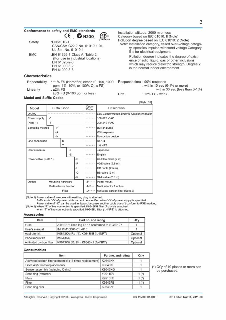
±3% FS (0-100 ppm or less)Model and Suffix Codes
Model Suffix Code DescriptionOptionCode
OX400 Low Concentration Zirconia Oxygen Analyzer
Power supply -5 100-120 V AC
(Note 1) -3 200-240 V AC
Sampling method -P Built-in pump
-A With aspirator -N No suction device
Line connection R Rc 1/4
T 1/4 NPT
User’s manual -J Japanese
-E English
Power cable (Note 1) -D UL/CSA cable (2 m)
-F VDE cable (2.5 m)
-H GB cable (2.5 m)
-Q BS cable (2 m)
-R SAA cable (2.5 m)
Option Mounting hardware /P Panel mount
Multi selector function /MS Multi selector function
Filter /A Activated carbon filter (Note 2)
(Note 1) Power cable of two-pole with earthing plug is attached. Suffix code “-D” of power cable can not be specified when “-3” of power supply is specified. Power cable of “-D” can be used in Japan, because another cable doesn’t conform to PSE marking.(Note 2) When “R” of line connection is specified, K9643KH filter (Rc1/4) is attached, when “T” of line connection is specified, K9643KJ filter (1/4NPT) is attached.
[Style: S2]
3rd Edition Mar.14, 2011-00Mar.14, 2011-00, 2011-00
Installation altitude: 2000 m or lessCategory based on IEC 61010: II (Note)Pollution degree based on IEC 61010: 2 (Note)
Note: Installation category, called over-voltage catego-ry, specifies impulse withstand voltage.Category II is for electrical equipment.
Pollution degree indicates the degree of exist-ence of solid, liquid, gas or other inclusions which may reduce dielectric strength. Degree 2 is the normal indoor environment.
Response time : 90% response : within 10 sec (0-1% or more)
within 30 sec (less than 0-1%)Drift : ±2% FS / week
(*) Qt’y of 10 pieces or more can be purchased.
AccessoriesItem Part no. and rating Qt’y
Fuse A1113EF: Time-lag T3.15 conformed to IEC60127 1User’s manual IM 11M10B01-01, -01E 1Aspirator kit K9643KA (Rc1/4), K9643KB (1/4NPT) OptionalPanel mount kit K9643KC OptionalActivated carbon filter K9643KH (Rc1/4), K9643KJ (1/4NPT) Optional
ConsumablesItem Part no. and rating Qt’y
Activated carbon filter element kit (15 times replacement) K9643KK 1Filter kit (5 times replacement) K9643KL 1Sensor assembly (including O-ring) K9643KG 1Snap ring (retainer) Y9011EV 1 (*)Plate K9213FB 1 (*)Filter K9643FB 1 (*)Snap ring plier K9643ZE 1
4
All Rights Reserved. Copyright © 2009, Yokogawa Electric Corporation GS 11M10B01-01E
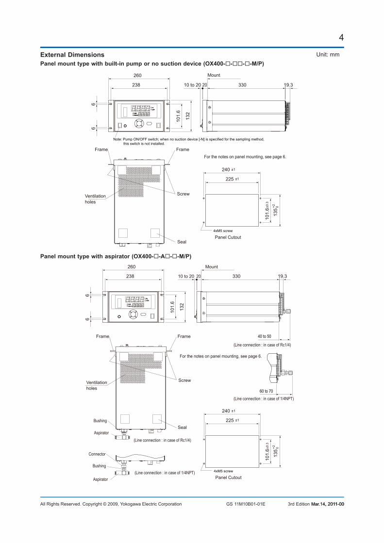
External DimensionsPanel mount type with built-in pump or no suction device (OX400----M/P)
135
+2 0
101.
6±0.
3
240 ±1
225 ±1
19.33302010 to 206
6
132
101.
6
260
238
Seal
Ventilationholes
FrameFrame
Screw
4xM5 screw
Panel Cutout
Mount
Note: Pump ON/OFF switch; when no suction device [-N] is specified for the sampling method, this switch is not installed.
For the notes on panel mounting, see page 6.
Panel mount type with aspirator (OX400--A--M/P)
40 to 50
(Line connection : in case of Rc1/4)
(Line connection : in case of Rc1/4)
(Line connection : in case of 1/4NPT)
(Line connection : in case of 1/4NPT)
Mount
Ventilationholes
Bushing
Bushing
Aspirator
Aspirator
Connector
4xM5 screw
Panel Cutout
60 to 70
101.
6±0.
3
135
+2 0
240 ±1
225 ±1
19.33302010 to 20
FrameFrame
Screw
Seal
66
132
101.
6
260
238
For the notes on panel mounting, see page 6.
3rd Edition Mar.14, 2011-00Mar.14, 2011-00, 2011-00
Unit: mm
5
All Rights Reserved. Copyright © 2009, Yokogawa Electric Corporation GS 11M10B01-01E
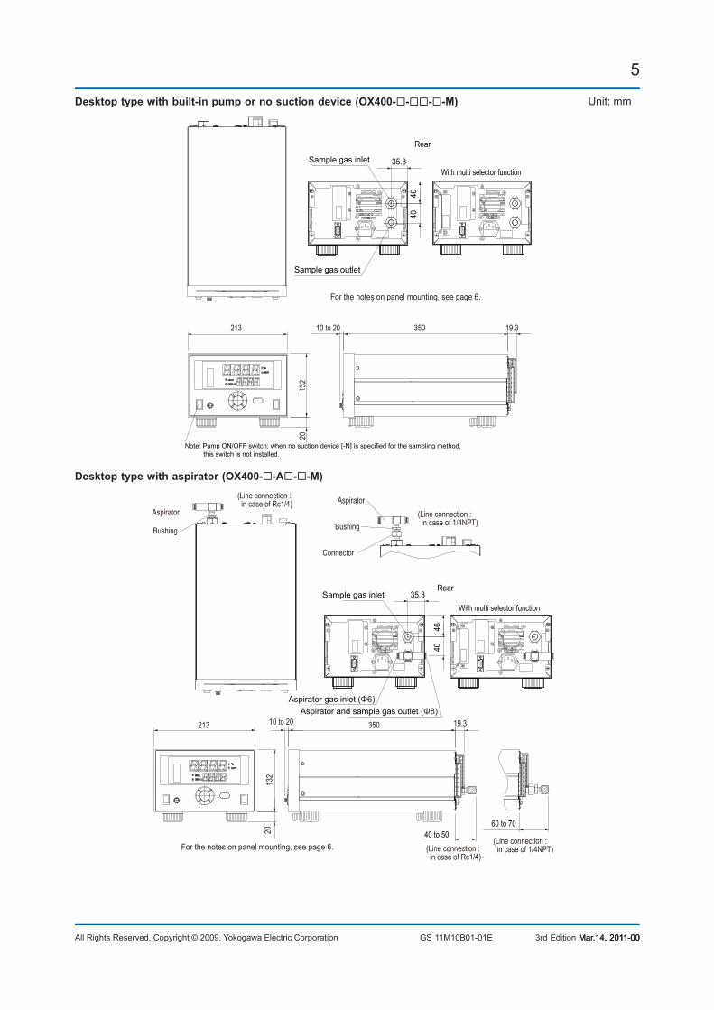
Desktop type with built-in pump or no suction device (OX400----M)
10 to 20213
132
20
350 19.3
Rear
Note: Pump ON/OFF switch; when no suction device [-N] is specified for the sampling method, this switch is not installed.
For the notes on panel mounting, see page 6.
With multi selector function35.3
40
Sample gas inlet
Sample gas outlet
46
Desktop type with aspirator (OX400--A--M)
With multi selector function
Rear
40 to 5060 to 70
(Line connection : in case of 1/4NPT)
(Line connection : in case of 1/4NPT)
(Line connection : in case of Rc1/4)
(Line connection : in case of Rc1/4)
Bushing Bushing
AspiratorAspirator
Connector
10 to 20213
132
20
350 19.3
Sample gas inlet
Aspirator gas inlet (Φ6)Aspirator and sample gas outlet (Φ8)
35.3
4640
For the notes on panel mounting, see page 6.
3rd Edition Mar.14, 2011-00Mar.14, 2011-00, 2011-00
Unit: mm
6
All Rights Reserved. Copyright © 2009, Yokogawa Electric Corporation GS 11M10B01-01E
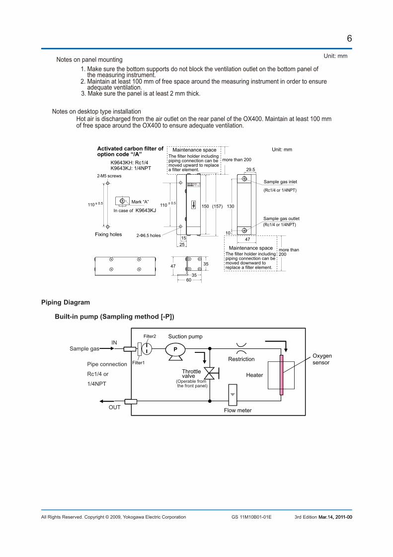
3. Make sure the panel is at least 2 mm thick.
2. Maintain at least 100 mm of free space around the measuring instrument in order to ensure adequate ventilation.
1. Make sure the bottom supports do not block the ventilation outlet on the bottom panel of the measuring instrument.
Notes on panel mounting
Hot air is discharged from the air outlet on the rear panel of the OX400. Maintain at least 100 mm of free space around the OX400 to ensure adequate ventilation.
Notes on desktop type installation
(Rc1/4 or 1/4NPT)
(Rc1/4 or 1/4NPT)
110
K9643KH: Rc1/4K9643KJ: 1/4NPT
± 0.5 ± 0.5
Unit: mm
Sample gas outlet
2-Ф6.5 holes
2-M5 screws
Mark “A”
In case of K9643KJ
Activated carbon filter of option code “/A”
Sample gas inlet
Fixing holes
more than 200
Maintenance spaceThe filter holder including piping connection can be moved upward to replace a filter element.
more than200
Maintenance spaceThe filter holder including piping connection can be moved downward to replace a filter element.
110 150 130
47
29.5
2515
10
(157)
35
35
60
47
Piping Diagram
PP
Throttlevalve
Flow meter
Suction pump
Heater
Oxygensensor
IN
OUT
Built-in pump (Sampling method [-P])
RestrictionFilter1
Filter2
Sample gas
Pipe connection
Rc1/4 or
1/4NPT (Operable from the front panel)
3rd Edition Mar.14, 2011-00Mar.14, 2011-00, 2011-00
Unit: mm
7
All Rights Reserved. Copyright © 2009, Yokogawa Electric Corporation GS 11M10B01-01E 3rd Edition Mar.14, 2011-00Mar.14, 2011-00, 2011-00
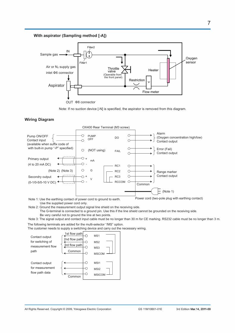
IN
OUT
Oxygensensor
With aspirator (Sampling method [-A])
Filter1
Filter2
Aspirator
Sample gas
Air or N2 supply gas
inlet Φ6 connector
Φ8 connector
Note: If no suction device [-N] is specified, the aspirator is removed from this diagram.
Flow meter
Heater
Restriction
(Operable from the front panel)
Throttlevalve
Wiring Diagram
MS1
MS2
MS3
MSI1
MSI2
MSICOM
MSCOM
1st flow path
2nd flow path
3rd flow path
OX400 Rear Terminal (M3 screw)
The following terminals are added for the multi-selector “/MS” option. The customer needs to supply a switching device and carry out the necessary wiring.
Contact outputfor switching ofmeasurement flowpath
Contact output for measurement flow path data
Common
Common
Common
PUMPOFF
mA
G
V
RC2
RC3
RCCOM
RC1
FAIL
DOPump ON/OFFContact input(available when suffix code of with built-in pump “-P” specified)
Secondry output
(0-1/0-5/0-10 V DC)
Power cord (two-pole plug with earthing contact)
Primary output
(4 to 20 mA DC)
+
-
+
-
Alarm(Oxygen concentration high/low)Contact output
Error (Fail)Contact output
Range marker Contact output
(Note 2) (Note 3)
(Note 1)
Note 1: Use the earthing contact of power cord to ground to earth. Use the supplied power cord only.Note 2: Ground the measurement output signal line shield on the receiving side. The G-terminal is connected to a ground pin. Use this if the line shield cannot be grounded on the receiving side. Be very careful not to ground the line at two points.Note 3: The signal output and contact input cable must be no longer than 30 m for CE marking. RS232 cable must be no longer than 3 m.
(NOT using)

8
All Rights Reserved. Copyright © 2009, Yokogawa Electric Corporation GS 11M10B01-01E 3rd Edition Mar.14, 2011-00Mar.14, 2011-00, 2011-00
Specifications Inquiry Sheet for OX400 Low Concentration Zirconia Oxygen Analyzer Please place checkmarks () in the pertinent boxes and filling in the blanks.
1. General informationName of your company: Name of inquirer: Dept. or sect.: (telephone: )Name of plant: Measuring point: Purpose of use: Indication Record Alarm ControlPower supply: V AC Hz
2. Process conditions(1) Measuring gas components: (2) Oxygen concentration: to , normally ppm O2 vol%O2
(3) Temperature: to , normally [°C](4) Pressure: to , normally [Pa](5) Gas flow: to , normally [ml/min](6) Dust: No dust Dust type Size to [μm] Quantity [g/Nm3](7) Other remarks:
3. Installation environment (1) Ambient temperature: to [°C](2) Vibration: No vibration Vibration (3) Installation: Desktop Built-in Others (4) Sampling method: Pump Aspirator No suction device
4. Specification requirements(1) Measuring range: to , normally ppm O2 vol%O2
(2) Output signal: 4-20 mA DC 0-1 V 0-5 V 0-10 V DC(3) Multi selector function (switching of measurement flow path) : Without With(4) Other remarks :
Subject to change without notice.