general electric - ge grid solutions · 2003-05-16 · gek-24994 general description the basic...
TRANSCRIPT
GEK-24994
INSTRUCTIONS
VALUTROL* MAIN CONTROL MODULEFULL WAVE, REGENERATIVE
i ...... -- I I III III I I I I I I I I I IIII
INSTALLATION - OPERATION - MAINTENANCE
!_!_'_Y::'i' F" ,-..c.af _?:_ELECTRIC
:[
F[
?hese tnstruet_ons do not purport to cover all details or variations m eqmpment nor to provide for every possible contingency to be met in
onneetion with installanon, operanon or maintenance. Should further mformahon be desJred or should particular problems ar_se which are not
_vered sufficiently for the purchaser's purposes, tbe matter should be referred to General Electric Company
GENERAL0 ELECTRIC_REGISTERED TRADEMARK OF GENERAL ELECTRIC COMPANY, U.S.A.
GEK-24994
TABLE OF CONI'ENTS
Page
GeneralDescription .............................................................................. 4
Power SupplyCard............................................................................. 4Main Control Card ............................................................................. 4
Auxiliary ControlCard.......................................................................... 4Test Instrument and Probe ...................................................................... 6Interface Card................................................................................. 8Motor Field Exciter Card ........................................................................ 9Motor Field Control Card ....................................................................... 9
DiagnosticCard................................................................................ 94.
Exciter and ControlPower ........................................ ............................. 10
SynchronizingSignal Power ....................................... '. ............................ 10Power Connections ............................................................................ 10
Control Connections........................................................................... 10ModificationRack............................................................................. 10
Start Up....................................................................................... 11
Sequence of Operations .......................................................................... 17PowerApplied................................................................................ 17
Switch Logic.................................................................................. 17Signal Flow .................................................................................. 17Stop ........................................................................................ 21DiagnosticStatic.............................................................................. 21
Logic ...................................................................................... 21SignalFlow ................................................................................ 22
DiagnosticRun ................................................................................ 22
CalibrationProcedure ........................................................................... 22
Calibration with Motor Field Control ............................................................. 23Calibration with Motor Field Exciter ............................................................. 25
Trouble Shooting ............................................................................... 27RecommendedInstrumentation ................................................................. 27
Procedures.................................................................................... 27
Removal/Repair ................................................................................. 27Printed Circuit Cards ........................................................................... 27
Glossaryof Terms........................................................................... 28, 29
Hot Line Telephone Number ............................................................... Back Cover
GEK-24994
LIST OF ILLUSTRATIONS
Figure Page
1 Typical VALUTROL Main Control Module Block Diagram ............................. 52 PowerSupplyCard ............................................................. 63 AuxiliaryControlCard .......................................................... 64 MainControlCard.............................................................. 75 InterfaceCard.................................................................. 86 Motor FieldExciter Card......................................................... 97 MotorFieldControlCard ........................................................ 9
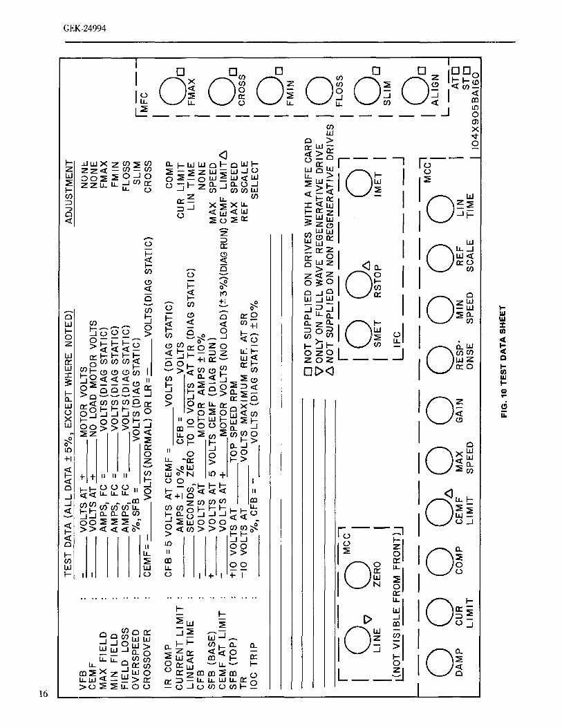
8 DiagnosticCard and Modification Rack ............................................ 109 Component and Signal Connection Location ........................................ 1210 TypicalTest DataSheet ........................................................ 1611 Current Feedback (CFB) at Low Current Level ..................................... 1812 Current Feedback (CFB) at Continuous Current Level ............................... 1813 VoltageFeedback(VFB) at LowCurrent ........................................... 1814 Voltage Feedback (VFB) at Continuous Current .................................... 1815 Oscillator(OSC)............................................................... 1916 InitialPulse (IPU)............................................................. 19
17 SynchronizingSignal (SA) ...................................................... 1918 SpeedFeedback Signal (SFB) with AC Tach 450 RPM ............................... 1919 Tachometer Feedback Signal (TFB) with AC Tach 450 RPM .......................... 2020 Tachometer Feedback Signal (TFB) with AC Tach 3160 RPM ......................... 2021 Speed Feedback Signal (SFB) with AC Tach 3160 RPM .............................. 2022 PulseOutput (PO) Normal...................................................... 2023 Diagnostic Test Circuits ........................................................ 2224 GainAdjustment .............................................................. 25
LIST OF TABLES
Table Page
I SignalConnections.............................................................. 13II FaultConditions............................................................... 15
III RecalibratingAdjustment Sequences .............................................. 23
GEK-24994
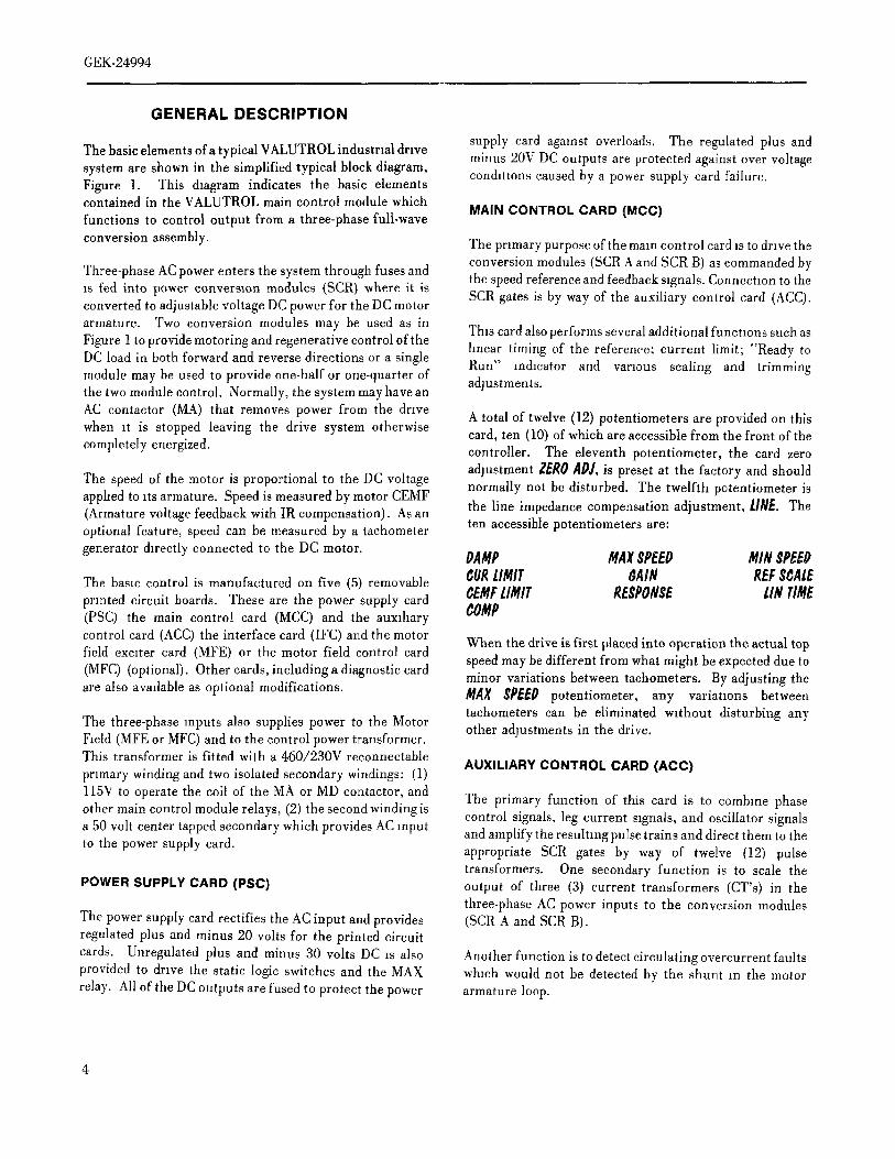
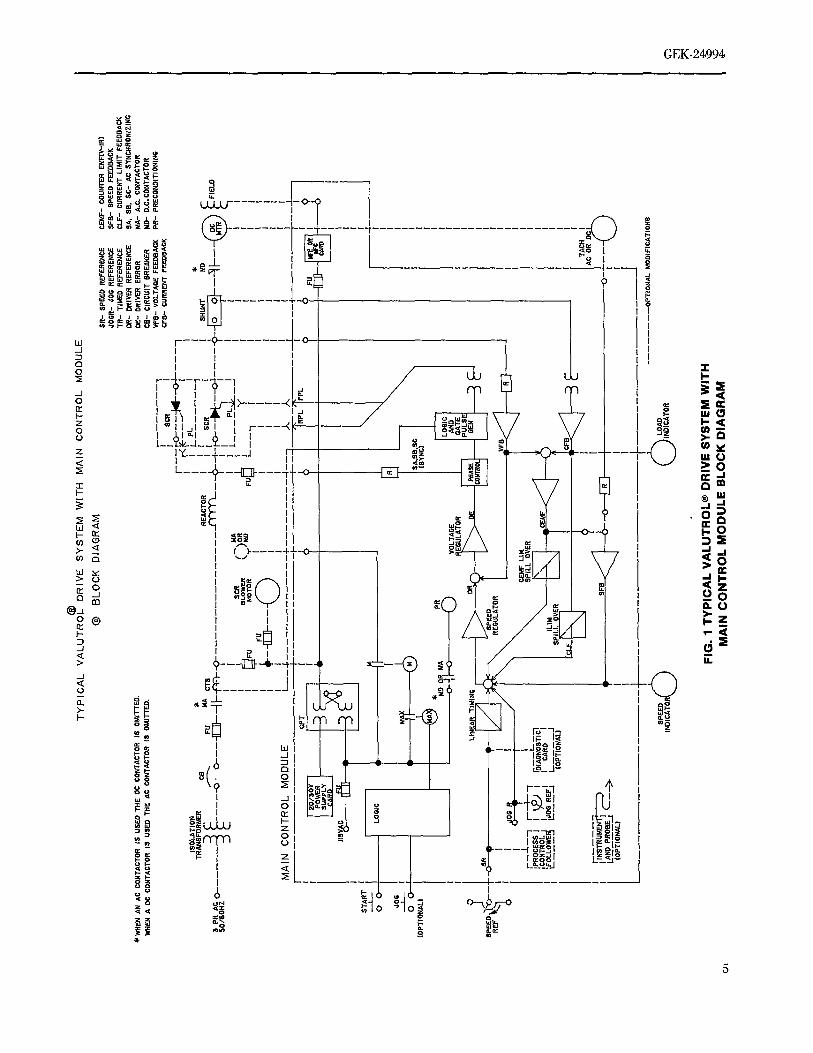
GENERAL DESCRIPTION
The basic elements ofa typicalVALUTROLindustnal drive supply card against overloads. The regulated plus andminus 20V DC outputs are protected against over voltage
system are shown in the simplified typical block diagram, condmons caused by a power supply card failure.Figure 1. This &agram indicates the basic elementscontained in the VALUTROL main control module which
MAIN CONTROL CARD (MCC)functions to control output from a three-phase full-wave
conversionassembly. The primarypurposeof themarecontrol cardis to drivetheconversion modules (SCR A and SCR B) as commanded by
Three-phase AC power enters the system through fuses and the speed reference and feedback signals. Connectmn to theis fed into power conversion modules (SCR) where it is SCR gates is by way of the auxiliary control card (ACC).converted to adjustable voltage DC power for the DC motor
armature. Two conversion modules may be used as in This card also performs several additional functmns such asFigure 1 toprovidemotoringandregenerativecontrolofthe hnear timing of the reference; current limit; "Ready toDC load in both forward and reverse directions or a single Run" m&cator and varmus scaling and trimmingmodule may be used to provide one-half or one-quarter ofthe two module control. Normally, the system may have an adjustments.AC contactor (MA) that removes power from the drive
A total of twelve (12) potentiometers are provided on thiswhen it is stopped leaving the drive system otherwise card, ten (10) of which are accessible from the front of the
completely energized, controller. The eleventh potentiometer, the card zero
adjustment ZEROADJ, is preset at the factory and shouldThe speed of the motor is proportional to the DC voltage normally not be disturbed. The twelfth potentiometer isapphed to _ts armature. Speed is measured by motor CEMF(Armature voltage feedback with IR compensation). As an the line impedance compensation adjustment, lINE. The
ten accessible potentiometers are:optional feature, speed can be measured by a tachometergenerator &rectly connected to the DC motor. PAMP MAX$PEEP MIN $PEEP
The basic control is manufactured on five (5) removable CURLIMIT $AIN REF$¢ALI_printed circuit boards. These are the power supply card CE/ifFLIMIT REgPONgE LINTilde(PSC) the main control card (MCC) and the auxlhary COMP
control card (ACC) the interface card (IFC) and the motor When the drive is first placed into operation the actual topfield exmter card (MFE) or the motor field control card speed may be different from what might be expected due to
(MFC) (optional). Other cards, including a diagnostic card minor variations between tachometers. By adjusting theare also avadable as optional modifications. MAX $PEE0 potentiometer, any variatlons between
tachometers can be eliminated without disturbing anyThe three-phase inputs also supplies power to the Motor other adjustments in the drive.Field (MFE or MFC) and to the control power transformer.This transformer is fitted with a 460/230V reconnectable
AUXILIARY CONTROL CARD (ACC)primary winding and two isolated secondary windings: (1)
l15V to operate the coil of the MA or MD contactor, and The primary function of this card is to combine phaseother main control module relays, (2) the second winding is control signals, leg current signals, and oscillator signalsa 50 volt center tapped secondary which provides AC input and amplify the resulting pulse trains and direct them to theto the power supply card. appropriate SCR gates by way of twelve (12) pulse
transformers. One secondary function is to scale thePOWER SUPPLY CARD (PSC) output of three (3) current transformers (CT's) in the
three-phase AC power inputs to the conversion modulesThe power supply card rectifies the AC input and provides (SCR A and SCR B).regulated plus and minus 20 volts for the printed circuit
cards. Unregulated plus and minus 30 volts DC _s also Another function is to detect circulating overcurrent faultsprovided to drive the static logic switches and the MAX whmh would not be detected by the shunt m the motorrelay. All of the DC outputs are fused to protect the power armature loop.
®T
YP
ICA
LV
ALU
TR
OL
DR
IVE
SY
ST
EM
WIT
HM
AIN
CO
NT
RO
LM
OD
ULE
©B
LOC
KD
IAG
RA
MS
R-
SP
EE
DR
EF
ER
EN
CE
CE
MF
-C
OU
I_'F
.RE
MF
(V,-
-IR
)4O
CR
-,J
OG
RE
FE
RE
NC
ES
FR
-S
PE
ED
FE
ED
BA
CK
'IR-
TIU
ED
RE
FE
RE
NC
EC
LF-
CU
RR
EN
TLI
MIT
FE
ED
BA
CK
DR
-D
RIV
ER
RE
FE
RE
NC
ES
A,
SB
.S
C-
AC
SY
NC
HR
ON
IZIN
G*W
HE
NA
NA
CC
DN
TA
CT
OR
iSU
SE
DT
HE
DC
CO
NT
AC
TO
RIS
OM
ITT
ED
.D
_-D
RIV
ER
ER
RO
RM
A-
A.C
.C
DN
TA
CT
OR
WH
EN
AD
CC
ON
TA
CT
OR
ISU
SE
DT
HE
AC
CO
NT
AC
TO
RIS
OM
ITT
ED
.C
B-
CIR
CU
ITB
RE
AK
ER
MD
-D
.C.C
ON
TA
CT
OR
VF
S-
VO
LTA
GE
FE
ED
BA
CK
PR
-P
RE
CO
ND
ITIO
NIN
GC
FS
-_R
RE
NT
EE
ED
BA
CK
!S
CR
r-__r2z-_:
z_--_
1I
I',F
*T,
IiS
OLA
TIO
_,
IL!
_...
...I
*T
RA
NS
FO
RM
ER
C5
RE
AC
TO
R]
!I
.___
_[
SH
UN
TM
D_
_::
o---
-[E
]]--_
l-y_-
_r
,'h
I_
'i'
,..M
,./$
PHAC
05O
/6O
HZ
II
]L_
__&
L_._
__!
'T"
_M
A
SC
Rf
'tOR
_I
IB
LOW
ER
'_._
,'/M
OI
YI
FU
MO
TO
RF
U_-
---_
I]
:A_
,,
I!
---
--I
II
I
MA
INC
ON
TR
OL
MO
DU
LEI
LL--
U_.
.__
II
II!
J.4-
---_
,/,A
,--
IJ
....
I
ST
AR
T--
-S
OO
LOG
IC
(OP
TIO
NA
L}
/_
*o_.
A_
/.I-
:%'-I
I!
·o
-..l,
i.---
o(D
:_O
_T_.
__/
I:.r.
_lI
RE
FI_
Q'--l
j]
T,,
RE
GU
LAT
OR
_RO
CE
SS
-]_
L'%
SP
ILL
OV
ER
,ED
NT
Ro'
,I
II
CA
RD
IL
JlM
M
LA._
_P._
O!_
,---
>_-
SFD
&_
O-T
----
-L._
.J{O
PT
ION
AL}
] 1S
pF_.
E_
f/"L_
//_LO
AD
OP
TIO
NA
LM
OD
IFIC
AT
ION
O
IND
ICA
TO
__,
,_F
IND
IC_T
OR
m t_F
IG.
1T
YP
ICA
LV
ALU
TR
OL®
DR
IVE
SY
ST
EM
WIT
H_
MA
INC
ON
TR
OL
MO
DU
LEB
LOC
KD
IAG
RA
M
GEK-24994
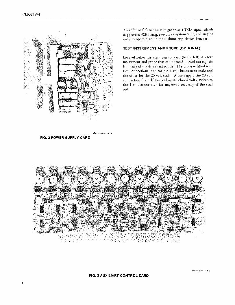
An additional function is to generate a TRIP signal which_: , ; suppresses SCR firing, executes a system fault, and may be
:' ,,y;,';- used to operate an optional shunt trip circuit breaker.
_, : TEST INSTRUMENT AND PROBE (OPTIONAL)
_"' ','_'E:: Located below the mare control card (to the left) is a test&:F' _?_, ' · -_, instrument and probe that can be used to read out signals
i,: - : from any of the drive test pomts. The probe is fitted with· ,_ _r'_2;
_5_(_ two connections, one for the 4 volt instrument scale and
[_, :, ?,_? :_ the other for the 20 volt scale. Always apply the 20 volt!_,,Y,:}:,, _3 _,'_'_ connection first. If the reading is below 4 volts, switch to
the 4 volt connecnon for improved accuracy of the read
_,_ _,_, out.
(P|mm MG 5246 201
FIG. 2 POWER SUPPLY CARD
!
_r_ :_ '
(Photo MG 5374 9)
FIG. 3 AUI([L[ARY CONTROL CAFIO
6
_-,
(:q_
)Q3
:_O
tlY'l
9NO
1YS
.LS
Od
.LS
3.L
:3.L
ON
)*_
I.-bZ
$_;-
_DIN
Old
VO
'IOI:I
J.N
O0
NIV
IN!_
'Old
·,
·,
·_
·_
_',,
__
__,
,_
,,_;
v;%
_%_7
%_
__
__,
_,._
,__l
_j_
___
-_-_
'_,
_,_'
,_
,,_
'_J_
·_'
_*_'
?._?
_:_'
_?*_
__
___
-_,
_,_'
_
GEK-24994
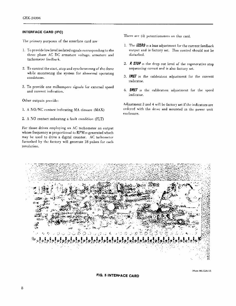
INTERFACE CARD (IFC)There are (4) potentiometers on this card.
The primary purposes of the interface card are-1. The IZEROis a bias adjustment for the current feedback
1. To provide lowlevel isolated slgnalscorrespondmgto the output and is factory set. Th_s control should not bethree phase AC DC armature voltage, armature and disturbed,tachometer feedback.
2. R $1'0P is the drop out level of the regenerative stop2. To control the start, stop and synchromzmg of the drive sequencing c]remt and is also factory set.
while momtormg the system for abnormal operatingconditions. 3. I/i_EI'is the cahbratlon adjustment for the current
mdlcator.
3. To provide one m]lhampere signals for external speedand current indication. 4. $MET is the eahbratlon adjustment for the speed
indicator.
Other outputs provide:Adjustment 3 and 4 will be factory set if the indicators are
1. A NO/NC contact indicating MA closure (MAX) ordered with the drive and mounted m the power unitenclosure.
2. A NO contact m&catmg a fault condition (FLT)
For those drives employing an AC tachometer an outputwhose frequency is proportional to RPM isgenerated whichmay be used to drive a digital counter. AC tachometerfurmshed by the factory will generate 18 pulses for eachrevolution.
.'..*_ :';.. _ ._.-_/}.'..%':;... ;¢.m.'.;".L"..r'/..%" '_ . '.;'/ '.'_. ; '..'_' ;..._".';.*:j;/_.:.:_.. "; ;' '_' :'4".. ' ' "./ ?5' ':q. '"' .'g4'._.;_Z:?; ..'/.'._.'%'_.. :;r ' ; -'_ 'd
. ' .... *';.'?".;?.'f..;"_;_;_°""'_'..f?%C._'_."'.""...' /".Yd_ "?;"_.'?'l'::""'_'"',';;';':';_'_"". 'z.' :_.`_.._`_;/t``_`_`%_._4_._:`_;_?;¢_.`_.Z;*.;_;;C_;_2_`"_:_% _ :' .
"_5 ,_ '? . " ' _ ' j
· ,i%i
(Photo MG-5236-13)
FIG. 5 ]NTERFACF CARD
8
GEK,24;
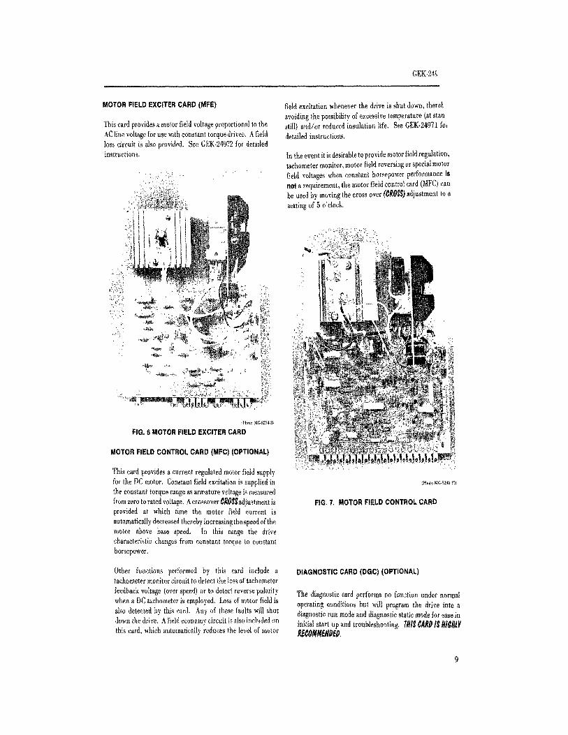
MOTORFIELDEXCITERCARD(MFE) field excitationwhenever the drive is shut down,theret,
avoidingthe possibilityof excessivetemperature(at stunThiscard providesa motor fieldvoltageproportionalto the still) and/or reducedinsulation life. See GEK.24971foeAC line voltage for use with constant torque drives, A field detailed instructions.loss circuit is also provided, See GEK-24972for detadedinstructions. In the eventit isdesirabletoprovidemotor fieldregulation,
tachometermonitor,motor fieldreversir;gor specialmotor
"_;,,y/ _'/. '-- ' field voltageswhen constant horsepowerperformanceis':,:__, _'?'-!::" nota requirement,the motor field controlcard (MFC)can
_' '_:"_ be used by movingthe cross over(¢RO_)adjustment to a, setting of 5 o'clock,
(P_olo MG.5_743_
FIG.6 MOTORFIELDEXCITERCARD
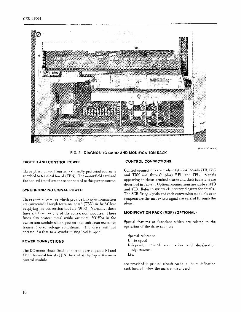
MOTORFIELDCONTROLCARD(MFC)(OPTIONAL)
This card provides a current regulated motor field supplyfor the DCmotor. Constantfield excitationis suppliedin !p_,,,,o_l¢-s,_l_lthe constant torque range as armature voltage is measuredfromzerotorated voltage.Acrossover¢_0$,_adjnstmentis FIG.7, MOTORFIELDCONTROLCARDprovided at which time the motor field current is
automatically decreased thereby increasing the speed of themotor above base speed. In this range the drivecharacteristic changes from constant torque to constanthorsepower,
Other functions performed by this card include a DIAGNOSTICCARD(DGC)(OPTIONAL)tachometermonitorcircuitto detect the lossof tachometer
feedbackvoltage{overspeed) or to detect reversepolarity The diagnosticcard performs no function under normalwhena DCtachometeris employed, Lossof motor fieldis operating conditionsbut will program the drive into aalso detectedby this card. Any of these faults will shut diagnosticrun modeand diagnosticstatic modefor easeindownthe drive. Afieldeconomycircuitis alsoincludedon initial start up and troubleshooting. T#I$¢llRPIg#/_l}tthis card, whichautomaticallyreducesthe level of motor _¢0_II./t_OEO,
GEK-24994
9 :-:::
7!i';::2;:;;;;721;¸
] 7
:::__,: __:_5i:!i:577,_'_
(Photo MG-5§93-1]
FIG. 8. DIAGNOSTIC CARD AND MODIFICATION RACK
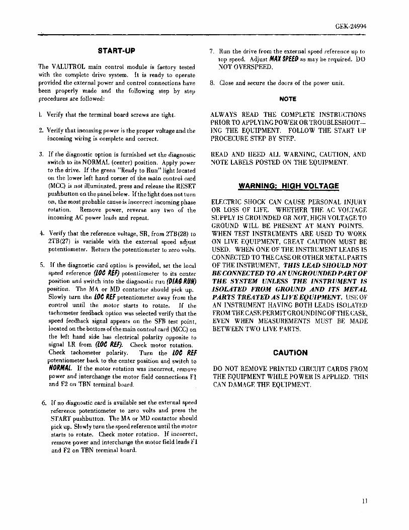
EXCITER AND CONTROL POWER CONTROL CONNECTIONS
Three phase power from an externally protected source is Control connections are made to terminal boards 2TB, TBCsupplied to terminal board (TBN). Themotor field cardand and TBN and through plugs RPL and FPL. Signalsthe control transformer are connected to this power source, appearing on these terminal boards and their functions are
described in Table 1. Optional connections are made at 3TBSYNCHRONIZING SIGNAL POWER and 4TB. Refer to system elementary diagram for details.
The SCR firing signals and each conversion module's over
Three resistance wires which provide line synchronization tempei'ature thermal switch signal are carried through theare connected through terminal board (TBN) to the AC line plugs.supplying the conversion module (SCR). Normally, theselines are fused in one of the conversion modules. These MODIFICATION RACK (MDR) (OPTIONAL)
fuses also protect metal oxide varistors (MOWs) in theconversion module which protect that unit from excessive Special features or functions which are related to thetransient over voltage conditions. The drive will not operation of the drive such as:operate if a fuse to a synchronizing lead is open.
Special referencePOWER CONNECTIONS Up to speed
Independent timed acceleration and deceleration
The DC motor shunt field connections are at points F1 and adjustmentsF2 on terminal board (TBN) located at the top of the main Etc.control module.
are provided in printed circuit cards in thc modificationrack located below the main control card.
10
GEK-24994
START-UP 7. Run the drive from the external speed reference up totop speed. Adjust MAXSPEEDas may be required. DO
The VALUTROL main control module is factory tested NOT OVERSPEED.with the complete drive system. It is ready to operateprovided the external power and control connections have 8. Close and secure the doors of the power unit.been properly made and the following step by stepprocedures are followed: NOTE
1. Verify that the terminal board screws are tight. ALWAYS READ THE COMPLETE INSTRUCTIONSPRIOR TO APPLYING POWER OR TROUBLESHOOT--
2. Verify that incoming power is the proper voltage and the lNG THE EQUIPMENT, FOLLOW THE START TIPincoming wiring is complete and correct. PROCECURE STEP BY STEP.
3. If the diagnostic option is furnished set the diagnostic READ AND HEED ALL WARNING, CAUTION, ANDswitch to its NORMAL (center) position. Apply power NOTE LABELS POSTED ON THE EQUIPMENT.to the drive. If the green "Ready to Run" light locatedon the lower left hand corner of the main control card
(MCC) is not illuminated, press and release the RESET WARNING: HIGH VOLTAGEpushbutton on the panel below. If the light does not turnon, the most probable cause is incorrect incoming phase ELECTRIC SHOCK CAN CAUSE PERSONAL INJURYrotation. Remove power, reverse any two of the OR LOSS OF LIFE. WHETHER THE AC VOLTAGEincoming AC power leads and repeat. SUPPLY IS GROUNDED OR NOT, HIGH VOLTAGE TO
GROUND WILL BE PRESENT AT MANY POINTS.
4. Verify that the reference voltage, SR, from 2TB(28) to WHEN TEST INSTRUMENTS ARE USED TO WORK
2TB(27) is variable with the external speed adjust ON LIVE EQUIPMENT, GREAT CAUTION MUST BEpotentiometer. Return the potentiometer to zero volts. USED. WHEN ONE OF TIfE INSTRUMENT LEADS IS
CONNECTED TO THE CASE OR OTHER METAL PARTS
5. If the diagnostic card option is provided, set the local OF THE INSTRUMENT, THIS LEAD SHOULD NOTspeed reference (10C REF)potentiometer to its center HE CONNECTED TO AN UNGROUNDED PART OFposition and switch into the diagnostic run (I}IA_RUN) THE SYSTEM UNLESS THE INSTRUMENT ISposition. The MA or MD contactor should pick up. ISOLATED FROM GROUND AND ITS METALSlowly turn the lOCREFpotentiometer away from the PARTS TREATED AS LIVE EQUIPMENT. USE OFcontrol until the motor starts to rotate. If the AN INSTRUMENT HAVING BOTH LEADS ISOLATED
tachometer feedback option was selected verify that the FROM THE CASE PERMIT GROUNDING OFTHE CASE,speed feedback signal appears on the SFB test point, EVEN WHEN MEASUREMENTS MUST BE MADElocated on the bottom of the main control card (MCC) on BETWEEN TWO LIVE PARTS.the left hand side has electrical polarity opposite tosignal LR from (lOC REF). Check motor rotation.Check tachometer polarity. Turn the lOC REt: CAUTIONpotentiometer back to the center position and switch toNORMAl. If the motor rotation was incorrect, remove DO NOT REMOVE PRINTED CIRCUIT CARDS FROMpower and interchange the motor field connections F1 THE EQUIPMENT WHILE POWER IS APPLIED. THISand F2 on TBN terminal board. CAN DAMAGETHE EQUIPMENT.
6. If no diagnostic card is available set the external speedreference potentiometer to zero volts and press theSTART pushbutton. The MA or MD contactor shouldpick up. Slowly turn the speed reference until the motorstarts to rotate. Check motor rotation. If incorrect,
remove power and interchange the motor field leads F1and F2 on TBN terminal board.
II
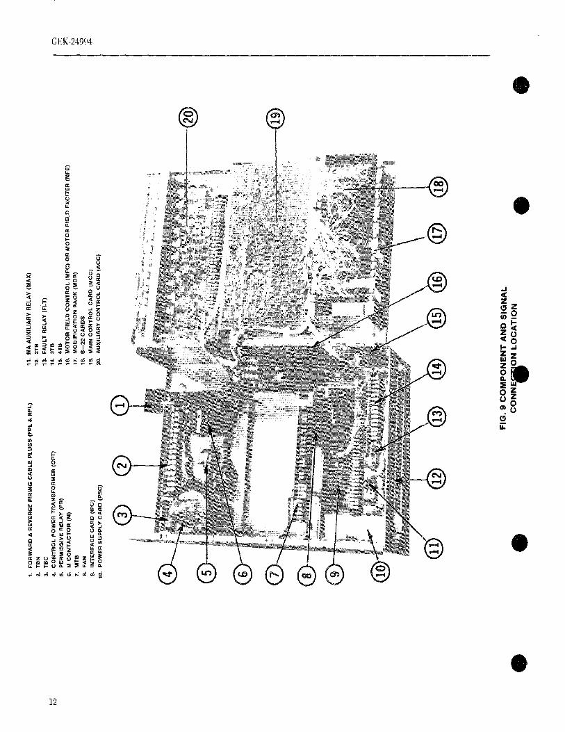
1.F
OR
WA
RD
&R
EV
ER
SE
FIR
ING
CA
BLE
PLU
GS
(FP
L&
RP
L)11
.M
AA
UX
ILIA
RY
RE
LAY
(MA
X)
2.T
SN
12.
2TS
3.T
BC
13.
FA
ULT
RE
LAY
[FLT
)
4.C
ON
TR
OL
PO
WE
RT
RA
NS
FO
RM
ER
(CP
T}
14.
3TB
5.
PE
RM
ISS
IVE
RE
LA
Y(PR
)1
5.4
TB
6.M
CO
NT
AC
TO
R(M
)16
.M
OT
OR
FIE
LDC
ON
TR
OL
(MF
C)
OR
MO
TO
RF
IELD
EX
CIT
ER
(MF
E)
?
7.M
TB
17.
MO
DIF
ICA
TIO
NR
AC
K'(M
DR
)_:
_
8,F
AN
18.
S--
22C
AR
DS
9.IN
TE
RF
AC
EC
AR
Dlit
'C)
lg.
MA
INC
ON
TR
OL
CA
RD
[MC
C)
,_
10.
PO
WE
RS
UP
PLY
CA
RD
(PS
C)
20.
AU
XIL
IAR
YC
ON
TR
OL
CA
RD
(AC
C)
}:
;2
:
o:
¢::
®@
®
_,G
.9C
OM
PO.E
.TA
.OS,
G.A
LC
O..E
_O.'O
CA
T,O
.O
GEK-24994
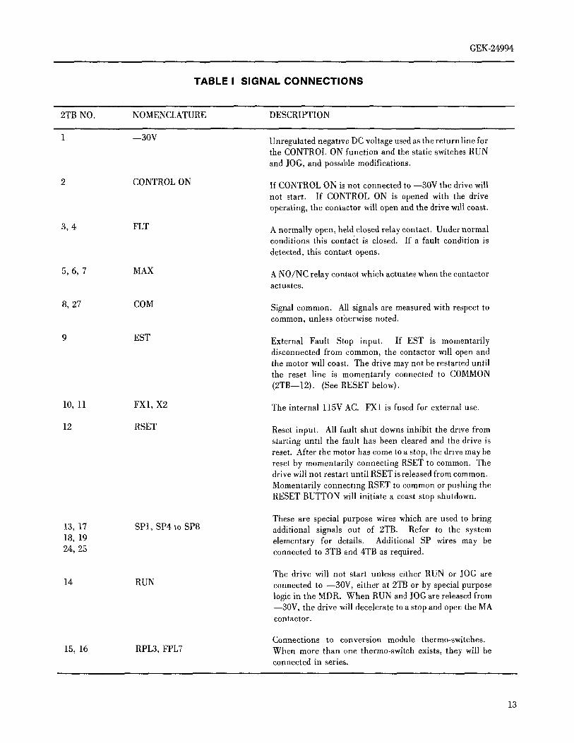
TABLE I SIGNAL CONNECTIONS
2TB NO. NOMENCLATURE DESCRIPTION
1 --30V Unregulated neganve DC voltage used as the returnline forthe CONTROL ON function and the static switches RUN
and JOG, and possible modifications.
2 CONTROLON If CONTROLON is not connected to --30V the drivewill
not start. If CONTROL ON is opened with the driveoperating, the contactor will open and the drive w_ll coast.
3, 4 FLT A normally open, held closed relay contact. Under normalconditions this contact is closed. If a fault condition is
detected, this contact opens.
5, 6, 7 MAX A NO/NC relay contact which actuates when the contactoractuates.
8, 27 COM Signalcommon. All signalsare measuredwithrespecttocommon, unless otherwise noted.
9 EST External Fault Stop input. If EST is momentarilydisconnected from common, the contactor will open andthe motor will coast. The drive may not be restarted untilthe reset line is momentarily connected to COMMON(2TB--12). (See RESET below).
10, 11 FX1,X2 The internal l15V AC. FX1is fused for externaluse.
12 RSET Reset input. All fault shut downsinhibit the drivefromstarting until the fault has been cleared and the drive isreset. After the motor has come to a stop, the drive may bereset by momentarily connecting RSET to common. Thedrive will not restart until RSET is released from common.
Momentarily connecting RSET to common or pushing theRESET BUTTON will initiate a coast stop shutdown.
These are special purpose wires which are used to bring13, 17 SP1, SP4 to SP8 additional signals out of 2TB. Refer to the system18, 19 elementary for details. Additional SP wires may be24,25 connectedto 3TBand4TBas required.
The drive will not start unless either RUN or lOG are
14 RUN connectedto --30V, either at 2TBor by specialpurposelogic in the MDR. When RUN and JOG are released from--30V, the drive will decelerate to a stop and open the MAcontactor.
Connections to conversion module thermo-switches.
15, 16 RPL3, FPL7 When more than one thermo-switch exists, they will beconnected in series.
13
CEK.24994
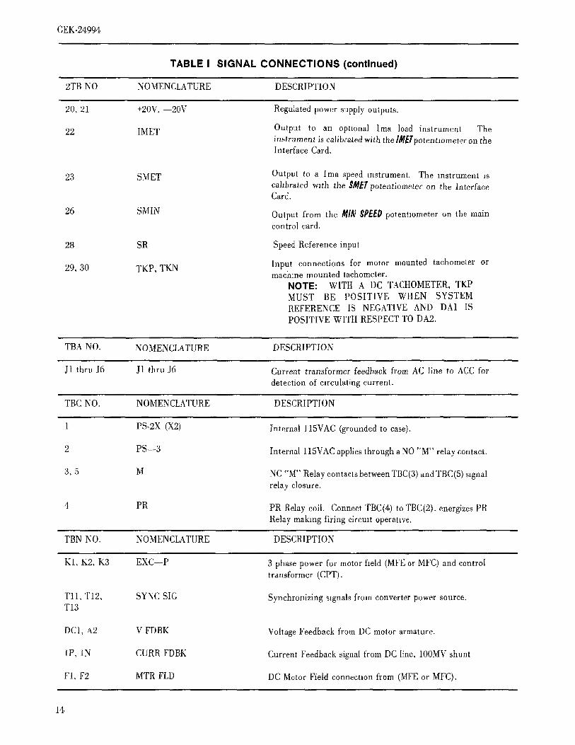
TABLE I SIGNAL CONNECTIONS (continued)
2TB NO NOMENCLATURE DESCRIPTION
20, 21 +20V, --20V Regulate) power supply outputs.
22 IMET Output to an optmnal lma load instrument Theinstrument is calibrated with the ]llf_Tpotentlometer on theInterface Card.
23 SMET Output to alma speed instrument. The instrument iscahbrated with the $/1_7'potentiometer on the InterfaceCard.
26 SMIN Output from the /l_lN$PEEP potentlometer on the maincontrol card.
28 SR Speed Reference input
29, 30 TKP, TKN Input connections for motor mounted tachometer ormachine mounted tachometer.NOTE: WITH A DC TACHOMETER, TKPMUST BE POSITIVE WHEN SYSTEMREFERENCE IS NEGATIVE AND DA1 ISPOSITIVE WITH RESPECT TO DA2.
TBA NO. NOMENCLATURE DESCRIPTION
J1 thru J6 J1 thru J6 Current transformer feedback from AC line to ACC for
detection of circulating current.
TBC NO. NOMENCLATURE DESCRIPTION
1 PS-2X(X2) Internalll5VAC(groundedto case).
2 PS--3 Internal 115VACappliesthroughaNO'_M"relaycontact.
3, 5 M NC"M"RelaycontactsbetweenTBC(3)andTBC(5)signalrelay closure.
4 PR PR Relaycoil. ConnectTBC(4)toTBC(2),energizesPR
Relay making firing circmt operative,
TBN NO. NOMENCLATURE DESCRIPTION
K1, K2, K3 EXC--P 3 phase power for motor field (MFEor MFC)and controltransformer (CPT).
Tll, T12, SYNC SIG Synchronizing signalsfrom converter power source.T13
DC1, A2 V FDBK Voltage Feedback from DC motor armature.
1P, 1N CURR FDBK Current Feedbacksignal from DC line, 100MVshunt
Fi, F2 MTRFLD DCMotor Field connectionfrom (MFEor MFC).
14
GEK-24994
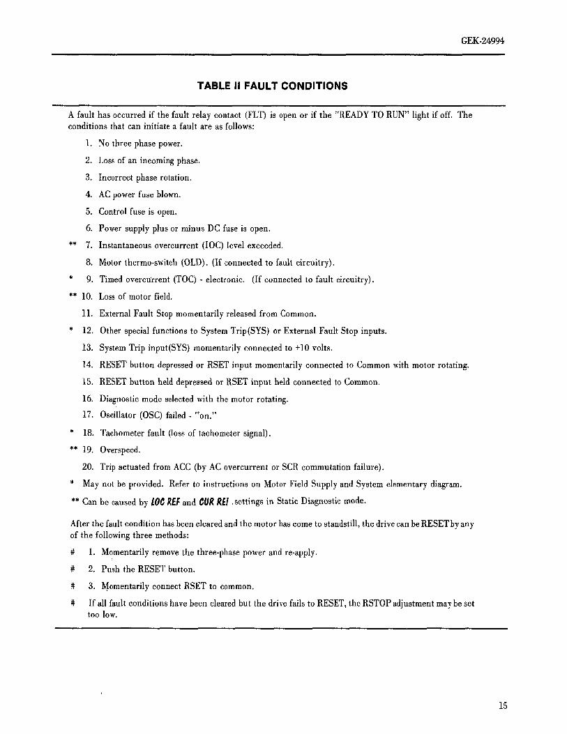
TABLE II FAULT CONDITIONS
A fault has occurred if the fault relay contact (FLT) is open or if the "READY TO RUN" light if off. Theconditions that can initiate a fault are as follows:
1. No three phase power.
2. Loss of an incoming phase.
3. Incorrect phase rotation.
4. AC power fuse blown.
5. Control fuse is open.
6. Power supply plus or minus DC fuse is open.
** 7. Instantaneous overcurrent (lOC) level exceeded.
8. Motor thermo-switch (OLD). (If connected to fault circuitry).
* 9. Timed overcuYrent (TOC) - electronic. (If connected to fault circuitry).
** 10. Loss of motor field.
11. External Fault Stop momentarily released from Common.
* 12. Other special functions to System Trip(SYS) or External Fault Stop inputs.
13. System Trip input(SYS) momentarily connected to +10 volts.
14. RESET button depressed or RSET input momentarily connected to Common with motor rotating.
15. RESET button held depressed or RSET input held connected to Common.
16. Diagnostic mode selected with the motor rotating.
17. Oscillator (OSC) failed-"on."
* 18. Tachometer fault (loss of tachometer signal).
** 19. Overspeed.
20. Trip actuated from ACC (by AC overcurrent or SCR commutation failure).
* May not be provided. Refer to instructions on Motor Field Supply and System elementary diagram.
** Can be caused by 10C REFand CURRE!. settings in Static Diagnostic mode.
After the fault condition has been cleared and the motor has come to standstill, the drive can be RESET by anyof the following three methods:
# 1. Momentarily remove the three-phase power and re-apply.
# 2. Push the RESET button.
# 3. Momentarily connect RSET to common.
# If all fault conditions have been cleared but the drive fails to RESET, the RSTOP adjustment may be settoo low.
15
TE
ST
DA
TA
(ALL
DA
TA
+5%
,E
XC
EP
TW
HE
RE
NO
TE
D)
AD
JUS
TM
EN
Tc_
VF
B:
-V
OLT
SAT
+M
OT
ORVO
LT
SN
ON
Eg:
CE
MF
:-
VO
LTS
AT
+N
OLO
AD
MO
TO
RV
OLT
SN
ON
EM
AX
FIE
LD:
AM
PS
_F
C=
VO
LTS
(DIA
GS
TA
TIC
)F
MA
XM
tNF
IELD
:.A
MP
S,
FC
=V
OLT
S(D
IAG
ST
AT
IC)
FM
INF
IELD
LOS
S:
AM
PS
,F
C=
VO
LTS
(DIA
GS
TA
TIC
)F
LOS
S
OV
ER
SP
EE
D:
%,S
FB
=V
OLT
S(D
IAG
ST
AT
IC)
SLI
MIM
FC
CR
OS
SO
VE
R:
CE
MF
=-
VO
LTS
(NO
RM
AL)
OR
LR=
--V
OLT
S(D
IAG
ST
AT
IC)
CR
OS
SI
IRC
OM
P:
CF
B=
5V
OLT
SA
TC
EM
F=
VO
LTS
(DIA
GS
TA
TIC
)C
OM
PI
CU
RR
EN
TLI
MIT
:A
MP
S+
10%
,C
FB
=V
OLT
SC
UR
LIM
ITI
_[]
LIN
EA
RT
IME
:S
EC
ON
DS
,Z
ER
OT
OI0
VO
LTS
AT
TR
(DIA
GS
TA
TIC
)LI
NT
IME
mF
MA
XC
FB
:-
VO
LTS
AT
.MO
TO
RA
MP
S_+
10%
NO
NE
IS
FB
(BA
SE
):
+V
OLT
SA
T5
VO
LTS
CE
MF
(D1A
GR
UN
)M
AX
SP
EE
D'
CE
MF
AT
LIM
IT:
-V
OLT
SA
T+
MO
TO
RV
OLT
S(N
OLO
AD
)(-
+3%
)(D
IAG
RU
N)
CE
MF
LIM
ITA
IS
FB
(TO
P)
:+
10V
OLT
SA
TT
OP
SP
EE
DR
PM
MA
XS
PE
ED
,'[]
TR
'-I
0V
OLT
SAT
VO
LT
SM
AX
IMU
MR
EF
.AT
SR
RE
FS
CA
LE
IC
RO
SS
lOC
TR
IP:
%,
CF
B=
-VO
LTS
(DIA
GS
TA
TIC
)-1
'10%
SE
LEC
TI !_
[]FM
INI
[]N
OT
SU
PP
LIE
DO
ND
RIV
ES
WIT
HA
MF
EC
AR
D!
VO
NL
YO
NF
UL
LW
AV
ER
EG
EN
ER
AT
IVE
DR
IVE
I{)
AN
OT
SU
PP
LIE
DO
NN
ON
RE
GE
NE
RA
TIV
ED
RIV
ES
I
'0
0'00
0I
.I
I_
II
[]
I(N
OTV
ISIB
LEF
RO
MFR
ON
T)J
LIF
CI
I i
t.J
mm
0000
0000
O0
i,A
T•
DA
MP
CU
RC
OM
PC
EM
FM
AX
GA
INR
ES
P'
MIN
RE
FLI
NJ
ST
OL
IMIT
LIM
ITS
PE
ED
ON
SE
SP
EE
DS
CA
LE
TIM
Ei
10
4X
90
5B
Ai6
0I
FIG
.10
TE
ST
DA
TA
SH
EE
T
GEK-24994
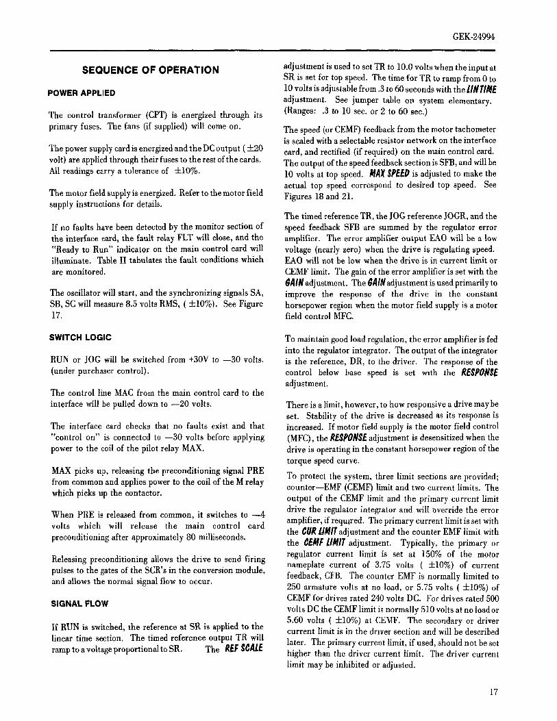
SEQUENCE OF OPERATION adjustment is used to set TR to 10.0 volts when the input atSR is set for top speed. The time for TR to ramp from 0 to10 volts is adjustable from .3 to 60 seconds with the II#HldE
POWER APPLIED adjustment. See jumper table on system elementary.
The control transformer (CPT) is energized through its (Ranges: .3 to 10 sec. or 2 to 60 sec.)
primary fuses. The fans (if supplied) will come on. The speed (or CEMF) feedback from the motor tachometeris scaled with a selectable resistor network on the interface
The power supply card is energized and the DC output ( +20 card, and rectified (if required) on the main control card.
volt) are applied through their fuses to the rest of the cards. The output of the speed feedback section is SFB, and will beAll readings carry a tolerance of +10%. 10 volts at top speed. MAXSPEEDis adjusted to make the
actual top speed correspond to desired top speed. SeeThe motor field supply is energized. Refer to the motor field Figures 18 and 21.supply instructions for details.
The timed reference TR, the lOG reference JOGR, and the
If no faults have been detected by the monitor section of speed feedback SFB are summed by the regulator errorthe interface card, the fault relay FLT will dose, and the amplifier. The error amplifier output EAO will be a low
"Ready to Run" indicator on the main control card will voltage (nearly zero) when the drive is regulating speed.illuminate. Table II tahulates the fault conditions which EAO will not be low when the drive is in current limit or
are monitored. CEMFlimit. Thegainof theerror amplifieris setwiththe$A/N adjustment. The $A/Nadjustment is used primarily to
The oscillator will start, and the synchronizing signals SA, improve the response of the drive in the constantSB, SC will measure 8.5 volts RMS, (+-10%), See Figure horsepower region when the motor field supply is a motor17. fieldcontrolMFC.
SWITCH LOGIC To maintain good load regulation, the error amplifier is fedinto the regulator integrator. The output of the integrator
RUN or JOG will be switched from +30V to --30 volts, is the reference, DR, to the driver. The response of the(under purchaser control), control below base speed is set with the RESPONSE
adjustment.The control line MAC from the main control card to the
interface will be pulled down to --20 volts. There is a limit, however, to how responsive a drive may be
set. Stability of the drive is decreased as its response isThe interface card checks that no faults exist and that increased. If motor field supply is the motor field control"control on" is connected to --30 volts before applying (MFC), the RESPONSEadjustment is desensitized when the
power to the coil of the pilot relay MAX. drive is operating in the constant horsepower region of thetorque speed curve.
MAX picks up, releasing the preconditioning signal PRE To protect the system, three limit sections are provided;from common and applies power to the coil of the M relay counter--EMF (CEMF) limit and two current limits. Thewhich picks up the contactor.
output of the CEMF limit and the primary current limitdrive the regulator integrator and will Override the errorWhen PRE is released from common, it switches to --4
volts which will release the main control card amplifier, if required. The primary current limit is set withthe CUR14MITadjustment and the counter EMF limit with
preconditioning after approximately 80 milliseconds.the _EMF lIMIT adjustment. Typically, the primary orregulator current limit is set at 150% of the motor
Releasing preconditioning allows the drive to send firing nameplate current of 3.75 volts (-t-10%) of current
pulses to the gates of the SCR's in the conversion module, feedback, CFB. The counter EMF is normally limited toand allows the normal signal flow to occur. 250 armature volts at no load, or 5.75 volts (+.10%) of
CEMF for drives rated 240 volts DC. For drives rated 500
SIGNAL FLOW volts DC the CEMF limit is normally 510 volts at no load or5.60 volts (4-10%) at CEMF. The secondary or driver
If RUN is switched, the reference at SR is applied to the current limit is in the driver section and will be described
linear time section. The timed reference output TR will later. The primary current limit, if used, should not be setramp to a voltage proportional to SR. The R_FSCAIE higher than the driver current limit. The driver current
limit may be inhibited or adjusted.
17
GEK-24994
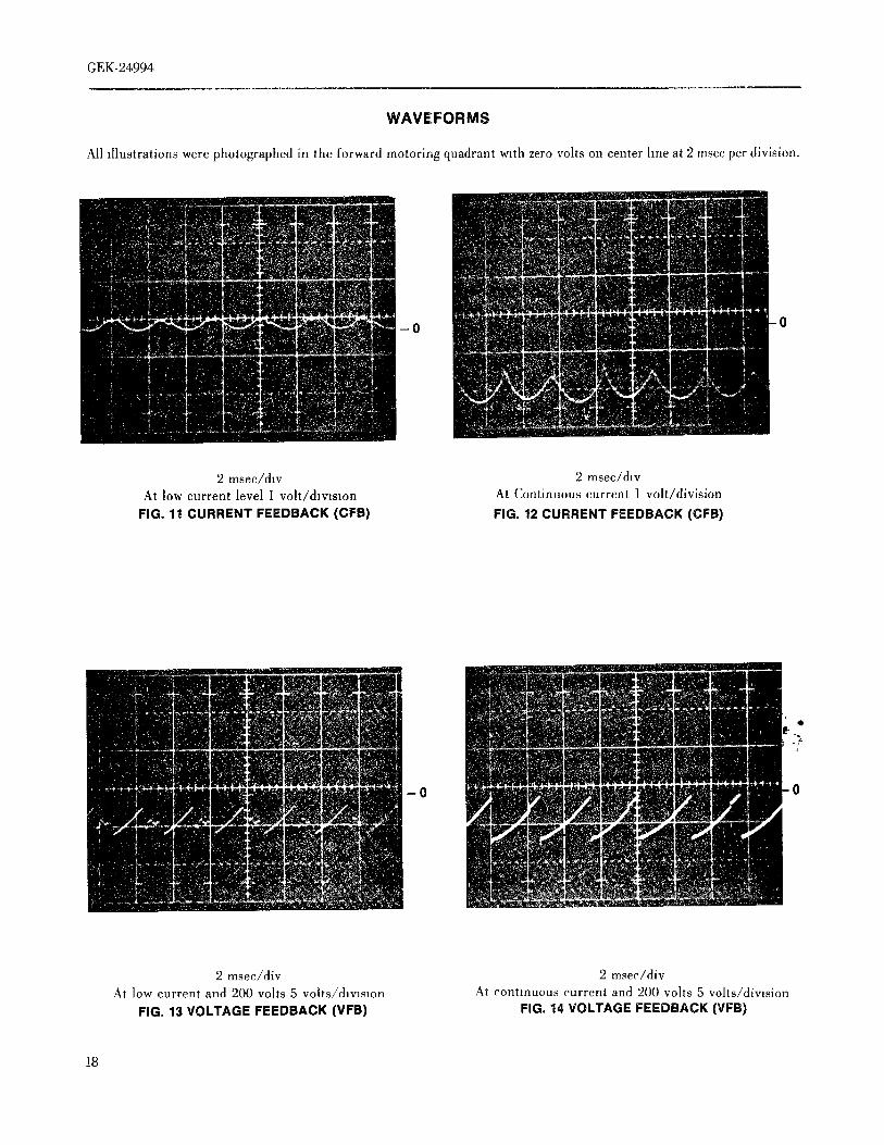
WAVE:FORMS
All illustrations were photographed in the forward motoring quadrant with zero volts on center line at 2 msec per division.
-0 0
2 msec/dlv 2 msec/d,vAt low current level 1 volt/division At Continuous current 1 volt/division
FIG. 11 CURRENT FEEDBACK (CFB) FIG. 12 CURRENT FEEDBACK (CFB)
* ·
_0 ;ami,,gm 0
2 msec/div 2 msec/divAt low current and 200 volts 5 volts/dmslon At continuous current and 200 volts 5 volts/division
FIG. 13 VOLTAGE FEEDBACK (VFB) FIG. *i4 VOLTAGE FEEDBACK (VFB)
18
GEK-24994
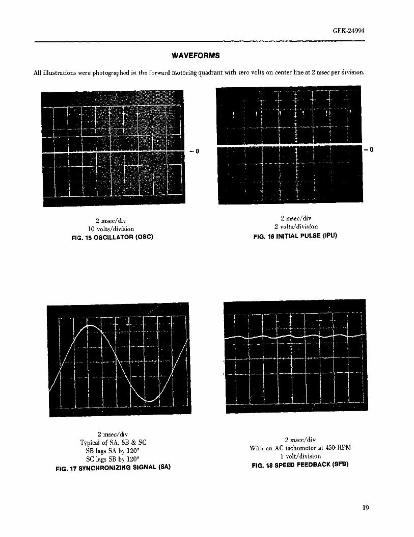
WAVEFORMS
All illustrations were photographed in the forward motoring quadrant with zero volts on center line at 2 msec per &vismn.
-0
-0
2 msec/div 2 msec/div10 volts/division 2 volts/division
FIG. 15 OSCILLATOR (OSC) FIG. 16 INITIAL PULSE (IPU)
2 msec/div
Typical of SA, SB & SC 2 msec/div
SBlagsSAby 120° With an ACtachometerat 45(_RPMSC lags SB b_ 120 ° 1 volt/division
FIG. 17 SYNCHRONIZING SIGNAL (SA) FIG. 18 SPEED FEEDBACK (SFB)
19
GEK.24994
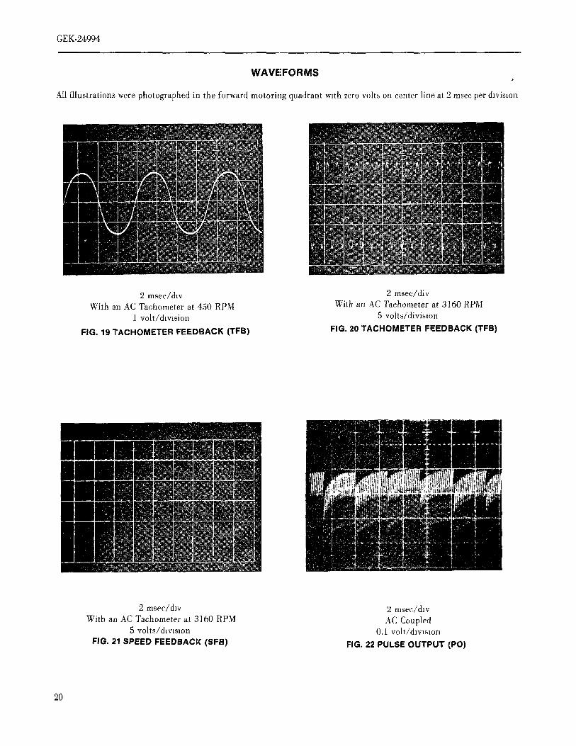
WAVEFORMS
Ail illustrations were photographed in the forward motoring quadrant with zero volts on center line at 2 msec per division
2 msec/&v 2 msec/divWith an AC Tachometer at 450 RPM With an AC Tachometer at 3_60 RPM
1 volt/division 5 vohs/divislon
FIG, 19 TACHOMETER FEEDBACK (TFB) FIG. 20 TACHOMETER FEEDBACK (TFB)
2 msec/dlv 2 msec/&v
With an AC Tachometer at 3160 RPM AC Coupled5 volts/d_vtslon 0.1 volt/&VlSlOn
FIG. 21 SPEED FEEDBACK (SFB) FIG. 22 PULSE OUTPUT (PO)
20
GEK-24994
RUN will switch from --30 volts to +30 volts. MAC will
The main purpose of the secondary, or driver, current limit switch to zero volts and the system reference input to theis to be an operating current limit if the regulator, or linear time section will be shunted to common.primary current limit, is not used and the system is
controlled by other signals summed at the driver junction. ,The timed reference TR will begin to time down to zero andThe driver current limit may be increased by connecting a the drive speed will come down accordingly.jumper from DC)( to DCY on the main control card whichwill increase the limit from approximately 130% to 175% of The regenerative stop circuit on the interface card will hold
the motor nameplate current. Alternative levels may be the contactor closed until the CEMF signal is almost zero,established by connecting a resistor betweenDCLandDCX corresponding to zero speed. At this time, theon the main control card. For normal levels of regulating preconditioning signal PRE goes to common, removingcurrent limit, either DCX should be jumpered on DCY to power from the MAX coil. 100 milliseconds later, MAX
increase the driver current hmit or it should be inhibited by drops out removing power from M, which then drops out.connecting DCI to COM. For regulating current hmit above The CEMF level corresponding to zero speed is set by the150%, a resistor should be connected between DCL and RgTOPadjustment. If RSTOPis set too far (CW), power isDCX to raise the driver limit above 175% or it should be
removed prematurely and the drive will coast into zeroinhibited with a jumper between DCI and COM.
speed. IfRSTOPis set too far (CCW) the contactor will not
The counter--EMF signal CEMF is developed on the main open at all.
control card by subtracting a signal proportional to the IR In some cases the regenerative stop circuit, (described
drop ofthe motor from voltage feedback. This is set with the above) may be under the control of the speed feedbackCOMP adjustment, signal, SFB, rather than the CEMF signal.
The driver reference, DR, the voltage feedback, VFB, an FAULTSTOP- Fault detected (See Table II) or CONTROL
armature current signal from damping adjustment, I)A_P, ON is open.and the driver current limit output are summed at the input
to the driver. The driver converts this error to pulse trains The preconditioning signal PRE is immediately applied towhich drive the SCR gates in such a manner as to maintain the main control card, forcing the drive into zero current orthe motor voltage proportionalto the driverreference. The coast conditions. As soon as the current goes to zero,damping adjustment l_AlflPcontrols the response of the preconditioning is established throughout the card.driver.
The contactor unconditionally drops out 100 millisecondsGenerally speaking, DAMPis used only to quiet small after the fault condmon occurs.oscillations which occur m the current under light load
conditions. Too much damping will slow down the system The drive can not be restarted until the motor has come toand response and tend to cause over shoot. rest. If the STOP was initiated by a fault, this is taken care
of automatically, but it is the purchaser's responsibility toThe driver provides a signal IPU to the oscillator on the not reclose "CONTROL ON" before the motor has come to
interface card to generate an initial pulse at the exact point rest. After the motor has stopped, push the RESET button.intimethatanSCRis tobefired.SeeFig.16.
DIAGNOSTIC STATIC (SWITCH TO LEFT)Two driver monitor points are available, PCR and PO. PCR
is the phase control reference which causes the output pulse LOGICtrains to phase shift in time with respect to the AC line. As
PCR moves from zero to +6 volts (+10%), the output pulses The RUN and JOG inputs are inhibited. This prevents thewill shift from full off to full on. PO is used to monitor the references SR and JOGR from activating the drive and
pulse outputs to the SCR's. See Fig. 22. holds the contactor open.
STOP The current reference potentiometer CURREFcontrols the
current feedback signal CFB.There are two stop sequences, normal stop and fault stop.
With a normal stop the drive regenerates to near zero speed The local reference lOC REFpotentiometer is connected
before opening the contactor. A fault stop opens the into the input of the hnear time section and into the speedcontactor and drive coasts to a stop. feedback section. The local reference is also connected to
the field diagnostic reference FDR. Refer to motor fieldNormal stop (disconnect RUN from --30 volts), control instructions (GEK-24971) for details of operation.
21
To simplify signal tracing, the gain of the regulator and The net effect Is the drive operates as a base speed voltagedrive is reduced and the speed feedback signal to the regulator from the [0¢ REFpotentlometer.regulator error amplifier is removed.
SIGNAL FLOW CALIBRATION PROCEDURE
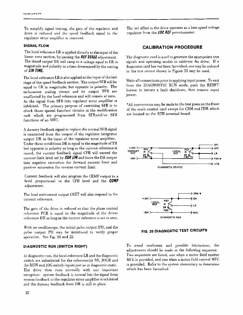
The local reference LR is applied directly to the input of thelinear time section, by-passing the R_F$¢,/1l_adjustment. The daagnostlc card is used to generate the appropriate testThe timed output TR will ramp to a voltage equal to LR in signals and operating modes to calibrate the drive. If amagnitude and polarity in a time determined by the setting &agnostic card has not been furnished, one may be orderedof lIN TI/V/_. or the test circuit shown in Figure 23 may be used.
The local reference LR is also applied to the input of the last
stage of the speed feedback section. The output SFB will be Make all connections prior to applying input power. To exitequal to LR in magnitude, but opposite in polarity. The from the DIAGNOSTIC RUN mode, push the RESETtachometer scaling circuit and its output TFB are button to initiate a fault shutdown, then remove inputunaffected by the local reference and will remain at zero. power.As the signal from SFB into regulator error amplifier _sinhibited. The primary purpose of exercising SFB is to *All connections may be made to the test posts on the frontcheck those specml function circuits m the modification of the main control card except for CRM and FUR whichrack whmh are programmed from SFB,and/or SFB are located on the RTB terminal board.functions of an MFC.
A dummy feedback signal to replace the normal SFB signalis connected from the output of the regulator integrator
output DR to the input of the regulator error amplifier.Under these conditions DR is equal to the magnitude of TR oPibut opposite in polarity as long as the current reference is +2ov_' REv - aEv -cv..E.. ,K Loc^.,K i >o.araised, the current feedback signal CFB will exceed the .ar zw _k.x>------_ azF aw_,[.-e T ) Lacurrent limit level set by t_lJR/IMand force the DR output -asr _ rid _ _ _WDTM r > r_a,into negative saturation for forward current limit and I > cv_positive saturation for reverse current limit, mAONOSTIC!iTATIC
Current feedback will also program the CEMF output to alevel proportional to the CFB level and the COMPadjustment.
The load instrument output IMET will also respond to the / >cam.current reference. +zovX _ - >UPI
LOCAL REVJ
The gain of the drive is reduced so that the phase control a£r _;_.__,tj%k,._LR
reference PCR is equal to the magnitude of the driver -a0v> '"-i ) _^creference DR as long as the current reference _sset to zero. DIAGNOSTICRON
With an oscilloscope, the initial pulse output IPU, and thepulse output PO may be monitored to verify proper FIG. 23 DIAGNOSTIC TEST CIRCUITSoperation. See Fig. 16 and 22.
DIAGNOSTIC RUN (SWITCH RIGHT) To avmd confusion and possible interaction, theadjustments should be made in the following sequence.
In diagnostic run, the local reference LR and the diagnostic Two sequences are listed, one when a motor field exciterswitch are substituted for the reference(s) SR, jOGR and MFE is provided, and one when a motor field control MFC
the RUN and JOG switch inputs just as m &agnostic static, is provided. Refer to the system elementary to determineThe drive then runs normally with one important which has been furnished.exception: system feedback is normal but the signal fromsystem feedback to the regulator error amplifier is inhibitedand the dummy feedback from DR is still in place.
22
GEK-24994
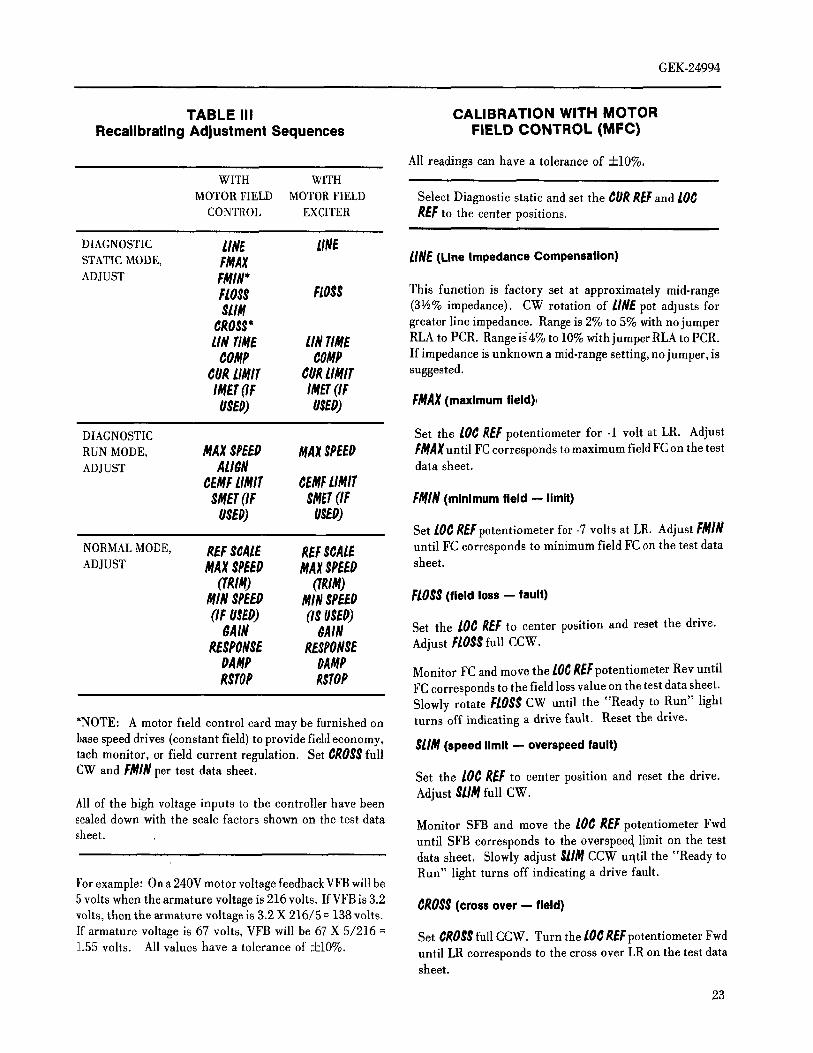
TABLE III CALIBRATION WITH MOTOR
Recalibrating Adjustment Sequences FIELD CONTROL (MFC)
All readings can have a tolerance of -4-10%,WITH WITH
MOTOR FIELD MOTORFIELD Select Diagnostic static and set the CURRE/:and LOC
CONTROL EXCITER REFto the center positions.
DIAGNOSTIC LIN_ LINE
STATIC MODE, FNAX tINE (Line Impedance Compensation)ADJUST FRIN*
FLOSS FLOSS This function is factory set at approximately mid-range
SLIM (3va% impedance). CW rotation of LINEpot adjusts forCROSS* greater line impedance. Range is 2% to 5% with no jumperLINTIRE LINTIME RLA to PCR. Range id4% to 10% with jumper RLA to PCR.
COMP COMP If impedance is unknown a mid-range setting, no jumper, is
CURLIMIT CURLIMIT suggested.
IMET(IF IMET(IFUSED) USED) FMAX(maximum fleld)_
DIAGNOSTIC Set the LOCREFpotentiometer for -1 volt at LR. Adjust
RUN MODE, MAXSPEED MAXSPEED FMAXuntil FC corresponds to maximum field FC on the testADJUST ALIDN data sheet.
¢EMFLIMIT ¢EMFLIMITSHET(IF SMET(IF FMIN (minimum field -- limit)OSEO) USED)
Set LOCREFpotentiometer for -7 volts at LR. Adjust FMIN
NORMALMODE, REFSCALE REFSCALE until FC corresponds to minimum field FC on the test data
ADJUST MAXSPEEO MAXSPEED sheet.
(TRIM) OgtM)MIN SPEED MI# SPEED FLOSS(field loss -- fault)(IF USED) (IS USED)
$AIN $AIN Set the lot REFto center position and reset the drive.RESPONSE RESPONSE Adjust FLOSSfull CCW.
DA_/IP OAMPRSTOP RSTOP Monitor FC and move the LOtREFpotentiometer Rev until
FC corresponds to the field loss value on the test data sheet.Slowly rotate FLOSSCW until the "Ready to Run" light
'NOTE: A motor field control card may be furnished on turns off indicating a drive fault. Reset the drive.
base speed drives (constant field) to provide field economy, SlIM (speed limit -- overspeed fault)tach monitor, or field current regulation. Set GROSSfull
CW and FMINper test data sheet. Set the lot REF to center position and reset the drive.
Adjust SLIMfull CW.All of the high voltage inputs to the controller have been
scaled down with the scale factors shown on the test data Monitor SFB and move the LOt REFpotentiometer Fwd
sheet, until SFBcorrespondsto the overspeec_limiton the testdata sheet. Slowly adjust SlimCCW uqtil the "Ready toRun" light turns off indicating a drive fault.
For example: On a 240V motor voltage feedback VFB will be
5 volts when the armature voltage is 216 volts. If VFB is 3.2 CROSS(cross over -- field)volts, then the armature voltage is 3.2 X 216/5 = 138 volts.
If armature voltage is 67 volts, VFB will be 67 X 5/216 = Set GROSSfull CCW. Turn the LOtREFpotentiometer Fwd
1.55 volts. All values have a tolerance of +10%. until LR corresponds to the cross over LR on the test datasheet.
23
GEK-24994
Monitor FC and adjust ¢R055 CW until FC just starts to ,;MET(speed instrument calibration)increase ¢ROg_may be checked when the drive is running
in normal operation by verifying that CEMF reads the value Turn the lO_R£Fpotentiometer until SFB is3 volts (±10%).on the test data sheet with the drive operating above base The optional speed indicator should md±cate 30% topspeed, speed. If _tdoesnot,pushtheRESETbuttonto initiatea
lINTIME(linear time) shut down. Remove power, adjust $liET and repeat.
Return the Diagnostic Switch to Normal.Monitor TR and set to zero wah the/OCREFpotent]ometer.
Rapidly turn the lOCREFfull Fwd and measure the time for REFSCAlE/MAX$PEEg(reference scale/max speed)TR to ramp to l0 volts(±10%), Adjust lINTIMEuntil this
time corresponds to the test data sheet linear time. Turn REFSeAl/; full CCW. Start the drive and apply top
COMP(compensation -- IR) speed reference to SR. Adiust the R_FSCAlEpotentiometeruntil SFB is lO volts (±10%). This normalizes the timed
Set the 10C REFpotent]ometer to center position. AdJust reference TR and speed feedback, SFB for 10volts(+10%)atthe CURREFpotentiometer Fwd or Rev until CFB is at 5 top speedvolts (=k10%).
Now measure motor RPM and adjust MAX SP£_I? (if
Momtor CEMF and adjust COMPuntil CEMF equals the necessary) until the actual RPM corresponds to the desiredvalue on the test data sheet, top speed. If actual top RPM was off by more than 5% reset
A/I$_I as detailed above.¢ORLIMIT(current limit)
RSTOP(regenerative stop)
Set CURl/lilT full CW. Adjust the C/JRREFpotentmmeter With the momtor operating at some RPM, call for a driveuntil CFB corresponds to the current limit level on the test stop by initiating the proper magnetics which will releasedata sheet. Momtor DR and turn C//RJlliIT CCW until DR 2TB-14 from --30 volts. The motor will decelerate to a low
just movesaway from zero. speed and the contactor willopen. If the contactor opensbefore the drive comes down to a stop, RSTOPis set too far
/MET(load instrument calibration) CW, If the contactor fails to open, RSTOPis set too farCCW. Push the RESET button to drop out the contactor
Adjust the CURREF until CFB corresponds to full load prior to removing power. RSTOPshould be readjusted withcurrent. Verify that the optional load instrument reads full power removed.
load. If not, remove power; adjust I/lETand repeat, lil_/$P_ (minimum speed)
Set the lOC R_Fto the center posltion; reset the driveand sw_tch to Diagnostm Run. Reduce the system reference to minimum and start the
drive. Adjust li[_/$PEEO, as required, to meet system
CE)IF//lilT (counter emf limit) minimum speed requirements. Refer to system elementaryfor mrcuit details.
Turn CE)IF L/MIT full CCW and turn the [0¢ REF _AIN, RESPONSE,gAIIPand ¢OliP (Stabilitypctentmmeter full Fwd. Adjust CE)IFl/lilT until CEMF adjustments)corresponds to the CE)IF//lilt on the test data sheet.
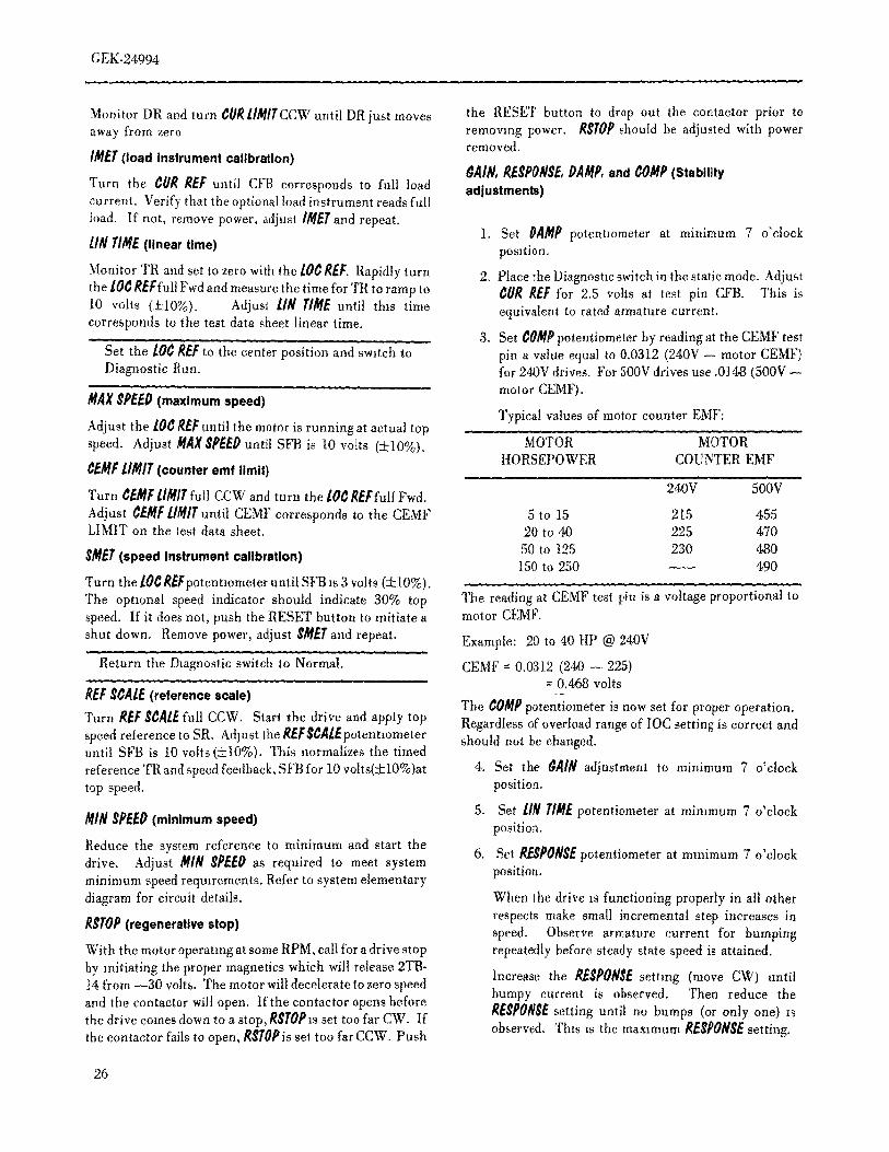
1 Set ÜAMP potentiometer at minimum 7 o'clock/flAX SPEEO/AI/_N(max speed/tachometer loss align- position.
fault). 2. Place the Diagnostic switch in the static mode. Adjust¢0R REF for 2.5 volts at test pin CFB. This is
Turn MAXSPEEDfull CW. Turn AII_N full CW. Adjust equivalent to rated armature current.the lOC REFpotentiometer until CEMF reads 5 volts (+10%)
Adjust ii/IX SPEEPuntil SFB corresponds to the base speed 3. Set ¢0MP potentiometer by reading at the CEMF testfeedbackon the test data sheet, pin a valueequal to 0.0312(240V-- motor CEMF)
for 240V drives. For 500V drives use .0148 (500V --Momtor TA and adjust AZI_N CCW until TA is motor CEMF).approximately zero volts.
Typical values of motor counter EMF:
24
GEK-24994
MOTOR MOTOR When the drive is functioningproperlyin all otherHORSEPOWER COUNTER EMF respects make small incremental step increases and
decreases in speed below base speed. Observe
240V 500V armature current for bumping repeatedly beforesteady state speed is attained.
5 to 15 215 45520 to 40 225 470 Increase the RESPONSEsetting (move CW) until50'to 125 230 480 bumpy current is observed. Then reduce the150 to 250 ---- 490 RESPONSEsetting tmtil no bumps (or only one) is
observed. This is the maximum RESPONSEsetting.
The reading at CEMF test pin is a voltage proportional In general, settings below 10 o'clock will show signsto motorCEMF. of increasingsluggishness.Settingsgreaterthan 2Example: 20 to 40 HP @ 240V o'clock may showsigns of hard or even continuousCEMF = 0.0312 (240- 225) bumping. Full RESPONSEsetting (5 o'clock) will
=0.468volts usuallytripthe lOC.
The C0MP potentiometer is now set for proper operation. 7. RESET lIN TIREto required setting.Regardless of overload range, lOC setting or motor fieldrange this setting is correct and should not be changed. CALIBRATION WITH MOTOR
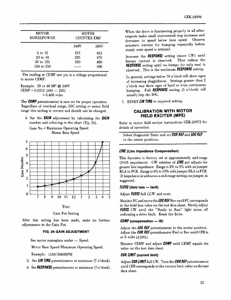
4. Set the _AIN adjustment by calculating the _AIN FIELD EXCITER (MFE)number and referring to the chart (Fig. 24). Refer to motor field exciter instructions GEK-24972 for
Gain No = Maximum Operating Speed details of operation,
Motor Base Speed Select Diagnostic Static and set CURREFand LOCREFto the center positions.
7 I i6/ LINE(Line Impedance Compensation)
5 // This functionis factoryset at approximatelymid-range
'_4 ' ' ); i (3V2%impedance). CW rotation of LINEpot adjusts for
Z / greater line impedance. Range is 2% to 5% with no jumper.9 3 , _,;. RLA to PCR. Range is 4% to 10% with jumper RLA to PCR.
2 ..... , _- ' If impedance is unknown amid-range setting, no jumper, is...... _ t-'"-' ' . suggested.
1 ,_ _ t-.'-'_' FLOSS(field loss -- fault)Z
...... AdjustFLOSSfull CCW and reset.0 7 8 9 10 11 12 I 2 3 4 5
Monitor FC and move the LOCREFRev until FC corresponds
Time to the fieldloss valueon the test data sheet. SlowlyadjustFLOSSCW until the '{Ready to Run" light turns off
Gain Pot Setting indicatinga drive fault. Reset the drive.
After this setting has been made, make no further COMP(compensation- IR)adjustments to the Gain Pot.
Adjust the LOCREFpotentiometer to the center position.FIG, 24[GAIN ADJUSTMENT Adjust the CURREFpotentiometer Fwd or Rev until CFB is
at 5 volts (+10%).See motor nameplate under -- Speed.
Monitor CEMF and adjust COMPuntil CEMF equals theMotor Base Speed/Maximum Operating Speed. value on the test data sheet.
Example: 1150/3600RPM CURL/MIT(current limit)
5. Set LINI/lifEpotentiometer at minimum (7 o'clock). Adjust CURLI_ITfull CW. Turn the ¢URf_EFpotentiometer
6. Set RESPONSEpotentiometer at minimum (7 o'clock), until CFB corresponds to the current limit value on the testdata sheet.
25
GEK-24994
Monitor DR and turn ¢UR/IMITCCW until DRjust moves the RESET button to drop out the contactor prior toaway from zero removing power. _$TOl}should be adjusted with power
removed./MET(load instrument calibration)
_AIN, REgl}ONSE,OAMI},and COMP(StabilityTurn the ¢OR REF until CFB corresponds to full load adjustments)current. Verify that the optional load instrument reads fullload. If not, remove power, adjust iMETand repeat.
1, Set DAMl}potentlometer at minimum 7 o'clocklin TIME(linear time) position.
Monitor TR and set to zero with the/0C REF. Rapidly turn 2. Place the Diagnostic switch in the static mode. Adjustthe L0CREFfull Fwd and measure the time for TR to ramp to CUR R£F for 2.5 volts at test pin CFB. This is10 volts (-+10%). Adjust l/N TIMEuntil this time equivalent to rated armature current.corresponds to the test data sheet linear time.
3, Set COMPpotentiometer by reading at the CEMF test
Set the 10C REFto the center position and switch to pin a value equal to 0,0312 (240V -- motor CEMF)Diagnostic Run. for 240V drives. For 500V drives use .0148 (500V
motor CEMF).MAXgl}EEO(maximum speed)
Typical values of motor counter EMF:Adjust the 10C gEFuntil the motor is running at actual topspeed. Adjust MAX$I}EE0until SFB is 10 volts (_+10%). MOTOR MOTOR
HORSEPOWER COUNTER EMF¢EltfFl/MIT (counter emf limit)
Turn C_MF//MIT full CCW and turn the lOCREFfull Fwd. 240V 500V
Adjust CEMFlIMITuntil CEMF corresponds to the CEMF 5 to 15 215 455LIMITonthe testdatasheet, 20to40 225 470
$MET(speed Instrument calibration) 50 to 125 230 480150to250 ---- 490
Turn the/0¢ REFpotentlometer until SFB is 3 volts (_+10%).The optional speed indicator should indicate 30% top The reading at CEMF test pin is a voltage proportional tospeed. If it does not, push the RESET button to initiate a motor CEMF.
shut down, Remove power, adjust $MEl'and repeat. Example: 20 to 40 HP @ 240V
Return the Dmgnostic switch to Normal. CEMF _ 0.0312 (240 -- 225)= 0.468 volts
REFSCALE(reference scale) The _OMl}potentiometer is now set for proper operation.Turn REFStAlEfull CCW, Start the drive and apply top Regardless of overload range of IOC setting is correct andspeed reference to SR, Adjust the/_EF$CAlEpotentlometer should not be changed.until SFB is 10 volts (:k10%). This normalizes the timedreference TRend speed feedback, SFB for lOvolts(±10%)at 4, Set the _JlIN adjustment to minimum 7 o'clocktopspeed, position.
Miff $l}EED(minimum speed) 5. Set lift T/MEpotentiometer at mimmum 7 o'clockposition.
Reduce the system reference to minimum and start the6. Set REgl}ONSEpotentiometer at minimum 7 o'clock
drive. Adjust MIN gl}EEO as required to meet system
minimum speed reqmrements, Refer to system elementary position.diagram for circuit details. When the drive is functioning properly in all other
RgTOP(regenerative stop) respects make small incremental step increases inspeed. Observe armature current for bumping
With the motor operating at some RPM, call for adrive stop repeatedly before steady state speed is attained,by initiating the proper magnetics which will release 2TB-14 from _30 volts. The motor will decelerate to zero speed Increase the RESPOfl_Esetting (move CW) until
bumpy current is observed. Then reduce the
and the contactor will open. If the contactor opens before RE$I}ONSEsetting until no bumps (or only one) isthe drive comes down to a stop, RSTOI}]s set too far CW. Ifthe contactor fails to open, RSTOl}isset too farCCW. Push observed, This is the maxlmum/_ESP0_/$E setting.
26
GEK-24994
In general, setting below 10 o'clock will show signs of Detailed adjustments for these two cards are found in GEK-increasing sluggishness. Settings greater than 2 24971 for the MFC card and GEK-24972 for the MFE card.o'clock may show signs of hard or even continuousbumping. Full RESPONSEsetting (5 o'clock) willusually trip the lOC. REMOVAL/REPAIR
7. Reset lin TIMEto required setting.PRINTED CIRCUIT CARDS
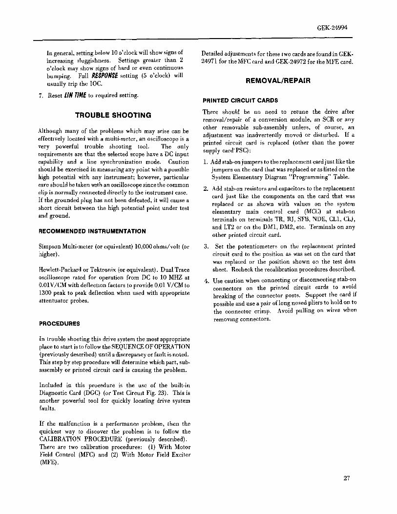
TROUBLE SHOOTING There should be no need to retune the drive afterremoval/repair of a conversion module, an SCR or anyother removable sub-assembly unless, of course, an
Although many of the problems which may arise can be adjustment was inadvertently moved or disturbed. If aeffectively located with a multi-meter, an oscilloscope is avery powerful trouble shooting tool. The only printed circuit card is replaced (other than the powerrequirements are that the selected scope have a DC input supply card*PSC):capability and a line synchronization mode. Caution 1. Add stab-on jumpers to the replacement cardjustliketheshould be exercised in measuring any point with a possible jumpers on the card that was replaced or as listed on thehigh potential with any instrument; however, particular System Elementary Diagram "Programming" Table.
care should be taken w_than oscilloscope since the common 2. Add stab-on resistors and capacitors to the replacementclip is normally connected directly to the instrument case. card just like the components on the card that wasIf the grounded plug has not been defeated, it will cause a replaced or as shown with values on the systemshort circuit between the high potential point under test elementary main control card (MCC) at stab-onand ground, terminals on terminals TR, RJ, SFB, NDE, CL1, CLJ,
and LT2 or on the DM1, DM2, etc. Terminals on anyRECOMMENDED INSTRUMENTATIONother printed circuit card.
Simpson Multi-meter (or equivalent)10,000ohms/volt (or 3. Set the potentiometers on the replacement printedhigher), circuit card to the position as was set on the card that
was replaced or the position shown on the test dataHewlett-Packard or Tektronix (or equivalent). Dual Trace sheet. Recheck the recalibration procedures described.oscilloscope rated for operation from DC to 10 MHZ at 4. Use caution when connecting or disconnecting stab-on
0.01V/CM withdeflectlon factors to provide 0.01 V/CMto connectors on the printed circuit cards to avoid
1300 peak to peak deflection when used with appropriate breaking of the connector posts. Support the card ifattentuator probes, possible and use a pair of long nosed pliers to hold on to
the connector crimp. Avoid pulling on wires when
PROCEDURES removing connectors.
In trouble shooting this drive system the most appropriateplace to start is to follow the SEQUENCE OF OPERATION(previously described) until a discrepancy or fault is noted.This step by step procedure will determine which part, sub-assembly or printed circuit card is causing the problem.
Included in this procedure is the use of the built-inDiagnostic Card (DGC) (or Test Circmt Fig. 23). This isanother powerful tool for quickly locating drive systemfaults.
If the malfunction is a performance problem, then thequickest way to discover the problem is to follow theCALIBRATION PROCEDURE (previously described).There are two calibration procedures: (1) With MotorField Control (MFC) and (2) With Motor Field Exciter(MFE).
27
GEK-24994
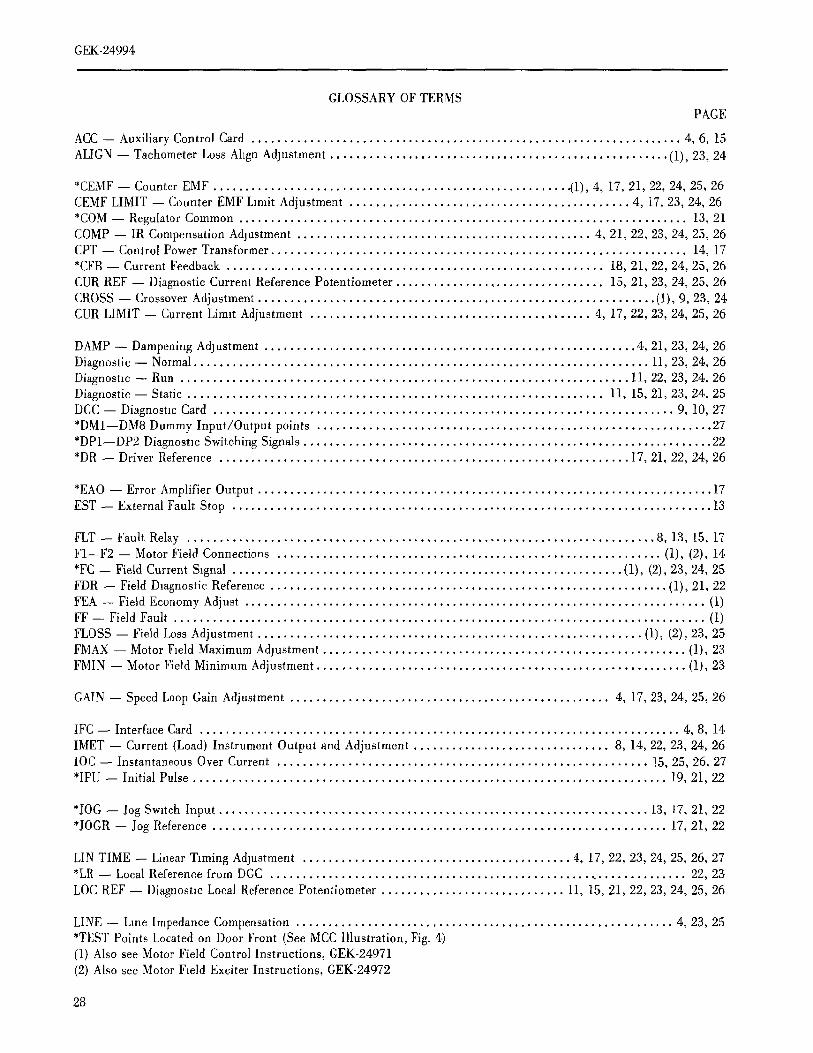
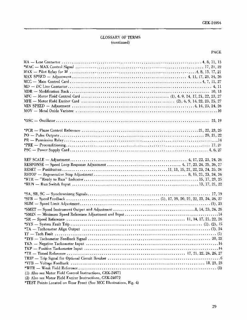
GLOSSARY OF TERMSPAGE
ACC -- Auxiliary Control Card ................................................................... 4, 6, 15
ALIGN -- Tachometer Loss Align Adjustment ..................................................... (1), 23, 24
*CEMF -- Counter EMF ........................................................ (1), 4, 17, 21, 22, 24, 25, 26CEMF LIMIT -- Counter EMF Limit Adjustment ............................................ 4, 17, 23, 24, 26*COM-- Regulator Common ...................................................................... 13, 21COMP -- IR Compensation Adlsstment .............................................. 4, 21, 22, 23, 24, 25, 26CPT -- Control Power Transformer ................................................................. 14, 17*CFB -- Current Feedback ........................................................... 18, 21, 22, 24, 25, 26
CUR REF -- Diagnostic Current Reference Potentiometer ................................. 15, 21, 23, 24, 25, 26CROSS-- CrossoverAdjustment .............................................................. (1), 9, 23, 24CUR LIMIT -- Current Limit Adjustment ............................................ 4, 17, 22, 23, 24, 25, 26
DAMP -- Dampening Adjustment .......................................................... 4, 21, 23, 24, 26Diagnostic -- Normal ....................................................................... 11, 23, 24, 26Diagnostic -- Run ...................................................................... 11, 22, 23, 24, 26Diagnostic -- Static ................................................................. 11, 15, 21, 23, 24, 25DCC-- DiagnosticCard ........................................................................ 9, 10,27*DM1--DM8 Dummy Input/Output points .............................................................. 27*DP1--DP2 Diagnostic Switching Signals ................................................................ 22*DR -- Driver Reference ................................................................ 17, 21, 22, 24, 26
*EAO-- Error Amplifier Output ....................................................................... 17
EST -- External Fault Stop ........................................................................... 13
FLT -- Fault Relay ......................................................................... 8, 13, 15, 17Fl--F2 -- Motor Field Connections ............................................................ (1), (2), 14*FC-- Field Current Signal ............................................................. (1), (2), 23, 24, 25
FDR -- Field Diagnostic Reference .............................................................. (1), 21, 22FEA -- Field Economy Adjust ........................................................................ (1)FF -- FieldFault ................................................................................... (1)
FLOSS -- Field Loss Adjustment ............................................................ (1), (2), 23, 25FMAX -- Motor Field Maximum Adjustment ......................................................... (1), 23
FMIN -- Motor Field Minimum Adjustment .......................................................... (1), 23
GAIN -- Speed Loop Gain Adjustment .................................................. 4, 17, 23, 24, 25, 26
IFC -- Interface Card ........................................................................... 4, 8, 14
IMET -- Current (Load) Instrument Output and Adjustment ............................... 8, 14, 22, 23, 24, 26lOC -- Instantaneous Over Current .......................................................... 15, 25, 26, 27*IPU -- Initial Pulse .......................................................................... 19, 21, 22
*JOG -- Jog Switch Input ................................................................... 13, 17, 21, 22*JOGR-- Jog Reference ....................................................................... 17, 21, 22
LIN TIME -- Linear Timing Adjustment .......................................... 4, 17, 22, 23, 24, 25, 26, 27*LR -- Local Reference from DGC ................................................................. 22, 23
LOC REF -- Diagnostic Local Reference Potentiometer ............................. 11, 15, 21, 22, 23, 24, 25, 26
LINE -- Line Impedance Compensation ........................................................... 4, 23, 25*TEST Points Located on Door Front (See MCC Illustration, Fig. 4)(1) Also see Motor Field Control Instructions, GEK-24971(2) Also see Motor Field Exciter Instructions, GEK-24972
28
GEK-24994
GLOSSARY OF TERMS
(continued)
PAGE
MA -- Line Contactor ........................................................................ 4, 8, 11, 13
*MAC -- MAX Control Signal .................................................................. 17, 21, 22MAX -- Pilot Relay for M ................................................................. 4, 8, 13, 17, 21MAX SPEED -- Adjustment ........................................................... 4, 11, 17, 23, 24, 26MCC -- Main Control Card .................................................................... 4, 7, 11, 27MD -- DC Line Contactor .......................................................................... 4, 11
MDR -- Modification Rack ........................................................................ 10, 13_IFC -- Motor Field Control Card .............................................. (1), 4, 9, 14, 17, 21, 22, 23, 27MFE -- Motor Field Exciter Card ................................................ (2), 4, 9, 14, 22, 23, 25, 27MIN SPEED -- Adjustment ............................................................... 4, 14, 23, 24, 26MOV -- Metal Oxide Varistor ......................................................................... 10
*OSC -- Oscillator ............................................................................... 15, 19
*PCR -- Phase Control Reference ............................................................ 21, 22, 23, 25
PO -- Pulse Outputs .......................................................................... 20, 21, 22PR -- PermissiveRelay............................................................................... 14*PRE -- Preconditioning .......................................................................... 17, 21
PSC -- Power Supply Card ....................................................................... 4, 6, 27
REF SCALE -- Adjustment ............................................................ 4, 17, 22, 23, 24, 26RESPONSE -- Speed Loop Response Adjustment ...................................... 4, 17, 23, 24, 25, 26, 27RESET -- Pushbutton ...................................................... 11, 13, 15, 21, 22, 23, 24, 25, 26
RSTOP -- Regenerative Stop Adjustment ................................................ 8, 15, 21, 23, 24, 26*RTR -- "Ready to Run" Indicator ........................................................... 15, 17, 23, 25*RUN -- Run Switch Input ................................................................. 13, 17, 21, 22
*SA, SB, SC -- Synchronizing Signals ............................................................... 17, 19*SFB -- Speed Feedback ................................................ (1), 17, 19, 20, 21, 22, 23, 24, 26, 27SLIM -- Speed Limit Adjustment ................................................................... (1), 23
*SMET -- Speed Instrument Output and Adjustment .......................................... 8, 14, 23, 24, 26*SMIN -- Minimum Speed Reference Adjustment and Input ................................................ 14*SR -- Speed Reference ............................................................. 11, 14, 17, 21, 22, 26*SYS-- SystemFault Trip .................................................................... (1), (2), 15*TA-- Tachometer Align Output .................................................................. (1), 24TF -- Tach Fault ................................................................................... (1)
*TFB-- Tachometer Feedback Signal ................................................................ 20, 22
TKN -- Negative Tachometer Input .................................................................... 14TKP -- Positive Tachometer Input ..................................................................... 14*TR -- Timed Reference ............................................................. 17, 21, 22, 24, 26, 27
TRIP -- Trip Signal for Optional Circuit Breaker .......................................................... 6
*VFB -- Voltage Feedback ..................................................................... 18, 21, 23*WFR -- Weak Field Reference....................................................................... (1)
(1) Also see Motor Field Control Instructions, GEK-24971(2) Also see Motor Field Exciter Instructions, GEK-24972
*TEST Points Located on Door Front (See MCC Illustrations, Fig. 4)
29
HOT LINE TELEPHONE NUMBER
The Contract Warranty for VALUTROL drives is stated in General Electric Apparatus Handbook Section 105,Page 7 !.
The purpose of the following is to provide specific instructions to the Valutrol--Drive user regarding warrantyadmhtistration and how to obtain assistance on out-of-warranty failures.
I. In the event of failure or misapplication during "in warranty" refer to the instruction book to identify thedefective part or subassembly.
2. When the defective part has been identified (or for assistance in identification)
General Electric Company
Erie, Pennsylvania
814--455--3219
(24 Hour Phone Service)
or
Contact the nearest
General Electric Installation and Service Engineering Office listed in your telephone d!rectory. Before calling,
list model numbers of the power unit and DC motor.
GENERAL ELECTRIC COMPANYSPEED VARIATOR PRODUCTS OPERATION
ERIE, PENNSYLVANIA 16531
GENERA[. ELECTRIC
GEK-24994(1/82) 600(P)