general + definite purpose contactors - schuh · general + definite purpose contactors ... unique...
TRANSCRIPT
visit www.sprecherschuh.com/ecatalog for pricing and the most up to date informationSSNA2018
A1
General + Definite Purpose Contactors
General Information .................................................................................. A2Horse Power Rating Charts .................................................................... A4Contact Life ........................................................................................... A8Contactor Number Structure ................................................................ A11
Series CA8 Miniature Contactors and Starters ......................................... A13Accessories ......................................................................................... A21Contactor Cross Reference................................................................... A23Technical Information & Dimensions (Online)........................................ A24
Series CA7 Contactors ............................................................................. A30Reversing ............................................................................................ A37Special Use CA7 Contactors ............................................................... A40 CNX Special Purpose ...................................................................... A41 NEMA Labeled Contactors ............................................................... A42 CA7Y2 Wye-Delta Contactors .......................................................... A44 CAL7 Lighting Rated ....................................................................... A45Accessories ......................................................................................... A47Renewal Coils ...................................................................................... A56Contactor Cross Reference................................................................... A58Technical Information & Dimensions (Online)........................................ A59
Series CA9 Contactors ............................................................................. A90Accessories ......................................................................................... A93Contactor Cross Reference................................................................... A98Technical Information & Dimensions (Online)........................................ A99
Series CA6 Contactors (Discontinued) .................................................... A120Accessories ....................................................................................... A129Renewal Coils .................................................................................... A134Contactor Cross Reference................................................................. A137Technical Information & Dimensions (Online)...................................... A138
Series CA5 Contactors (Discontinued) .................................................... A156Accessories ....................................................................................... A159Renewal Coils .................................................................................... A161Technical Information & Dimensions (Online)...................................... A163
Series CDP2 Definite Purpose Contactors ............................................... A178Accessories ....................................................................................... A184Technical Information & Dimensions (Online)...................................... A185
A
Con
tact
ors
A
Con
tact
ors
www.sprecherschuh.com/ecatalog - All pricing shown in US dollars

A2visit www.sprecherschuh.com/ecatalog for pricing and the most up to date information SSNA2018
A
Cont
acto
rs
www.sprecherschuh.com/ecatalog - All pricing shown in US dollars
Contactors – General Purpose and Definite Purpose
A rugged and comprehensive range of contactors from 5 to 900 HP
Sprecher + Schuh’s broad line of general purpose contactors combine performance and reliability in space saving designs that are well proven and used the world over. Sprecher + Schuh’s IEC design is dimensionally among the smallest devices in the industry. A range of definite purpose contactors is also available, providing reliable and economic performance in commercial applications.
Economy and selectionFour different contactor families pro-vide a wide variety of contactor sizes, one for practically every horsepower increment! The ability to select inter-mediate sizes assures a closer match for your motor and provides economy not found with traditionally sized devices. Definite purpose contactors are avail-able in one, two, three and four pole, up to 90A.
Precisely match the contactor to the applicationUnique to IEC-style contactors is the ability to select the exact device required for a specific application. By identifying the conditions under which the contactor will be used, i.e., resistive loads, reversing, inching and plugging, etc., published “life-curve” data predicts contact life in millions of operations. This information enables you to select the precise contactor for your application… without buying too much or too little.
Designed for long lifeDestructive electrical arcs are com-mon when opening or “breaking” the contacts of larger contactors. Sprecher + Schuh general purpose contactors are designed to dramatically reduce electrical arcing by quickly guiding the arc off of the contacts and into specially designed “arc chutes.” This special design divides and eliminates the electrical arcs quickly, significantly increasing contact life and assuring reliable operation.
Limitless choicesA comprehensive selection of modular accessories is available for all contactor families, which allows infinite contactor and starter combinations, both open and enclosed.
Safety in mind…Virtually all Sprecher + Schuh contactors are designed to be safe from accidental contact with the finger or back-of-hand. On the smaller contactors, terminals and set screws are recessed, while larger devices (up to Series CA9) accept terminal covers that provide protection according to VDE 0106, Part 100.
Manufactured to rigorous quality standardsSprecher + Schuh contactors are designed and manufactured in plants that maintain quality certification to the rigorous international standards, ISO 9001. Sprecher + Schuh manufac-turing facilities renew ISO certification every three years by passing an exact-ing quality assurance audit.
International standards and approvalsAll Sprecher+Schuh IEC contactors are cULus CSA Approved, along with several other certifications. They also carry the CE Mark and meet IEC 60947-1 requirements. They are ap-proved in virtually every international market.
Sprecher+Schuh IEC contactors are designed and manufactured in plants that are quality certified
to international standard ISO 9001
A3visit www.sprecherschuh.com/ecatalog for pricing and the most up to date informationSSNA2018
A
Cont
acto
rs
www.sprecherschuh.com/ecatalog - All pricing shown in US dollars
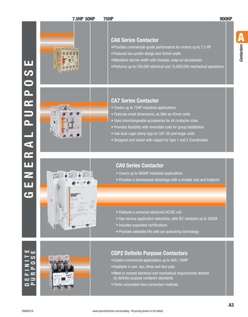
CA9 Series Contactor• Covers up to 900HP industrial applications
• Provides a dimensional advantage with a smaller size and footprint
• Features a universal electronic AC/DC coil
• Has various application selections, with IEC solutions up to 2650A
• Includes expanded certifications
• Provides extended life with arc quenching technology
CDP2 Definite Purpose Contactors• Covers commercial applications up to 90A / 50HP
• Available in one, two, three and four pole
• Meet or exceed electrical and mechanical requirements defined by definite purpose contactor standards
• Three convenient wire connection methods
CA7 Series Contactor• Covers up to 75HP industrial applications
• Features small dimensions, as little as 45mm wide
• Uses interchangeable accessories for all contactor sizes
• Provides flexibility with reversible coils for group installation
• Has dual-cage clamp lugs on CA7-30 and larger units
• Designed and tested with respect to Type 1 and 2 Coordination
CA8 Series Contactor• Provides commercial-grade performance for motors up to 7.5 HP
• Features low-profile design and 45mm width
• Maintains narrow width with modular, snap-on accessories
• Performs up to 700,000 electrical and 15,000,000 mechanical operations
7.5HP 50HP 75HP 900HP
GE
NE
RA
L P
UR
PO
SE
DE
FI
NI
TE
P U
RP
OS
E
A4visit www.sprecherschuh.com/ecatalog for pricing and the most up to date information SSNA2018
A
Cont
acto
rs
www.sprecherschuh.com/ecatalog - All pricing shown in US dollars
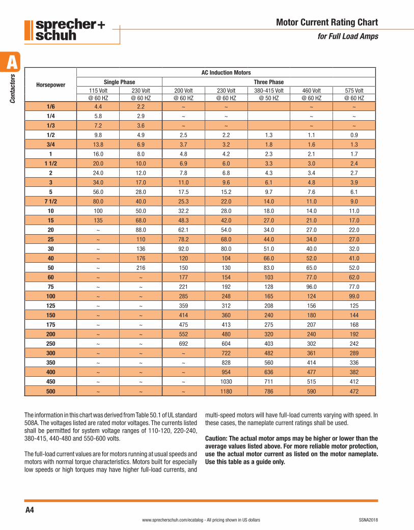
Motor Current Rating Chartfor Full Load Amps
The information in this chart was derived from Table 50.1 of UL standard 508A. The voltages listed are rated motor voltages. The currents listed shall be permitted for system voltage ranges of 110-120, 220-240, 380-415, 440-480 and 550-600 volts.
The full-load current values are for motors running at usual speeds and motors with normal torque characteristics. Motors built for especially low speeds or high torques may have higher full-load currents, and
multi-speed motors will have full-load currents varying with speed. In these cases, the nameplate current ratings shall be used.
Caution: The actual motor amps may be higher or lower than the average values listed above. For more reliable motor protection, use the actual motor current as listed on the motor nameplate. Use this table as a guide only.
Horsepower
AC Induction Motors
Single Phase Three Phase115 Volt 230 Volt 200 Volt 230 Volt 380-415 Volt 460 Volt 575 Volt@ 60 HZ @ 60 HZ @ 60 HZ @ 60 HZ @ 50 HZ @ 60 HZ @ 60 HZ
1/6 4.4 2.2 ~ ~ ~ ~
1/4 5.8 2.9 ~ ~ ~ ~
1/3 7.2 3.6 ~ ~ ~ ~
1/2 9.8 4.9 2.5 2.2 1.3 1.1 0.9
3/4 13.8 6.9 3.7 3.2 1.8 1.6 1.3
1 16.0 8.0 4.8 4.2 2.3 2.1 1.7
1 1/2 20.0 10.0 6.9 6.0 3.3 3.0 2.4
2 24.0 12.0 7.8 6.8 4.3 3.4 2.7
3 34.0 17.0 11.0 9.6 6.1 4.8 3.9
5 56.0 28.0 17.5 15.2 9.7 7.6 6.1
7 1/2 80.0 40.0 25.3 22.0 14.0 11.0 9.0
10 100 50.0 32.2 28.0 18.0 14.0 11.0
15 135 68.0 48.3 42.0 27.0 21.0 17.0
20 ~ 88.0 62.1 54.0 34.0 27.0 22.0
25 ~ 110 78.2 68.0 44.0 34.0 27.0
30 ~ 136 92.0 80.0 51.0 40.0 32.0
40 ~ 176 120 104 66.0 52.0 41.0
50 ~ 216 150 130 83.0 65.0 52.0
60 ~ ~ 177 154 103 77.0 62.0
75 ~ ~ 221 192 128 96.0 77.0
100 ~ ~ 285 248 165 124 99.0
125 ~ ~ 359 312 208 156 125
150 ~ ~ 414 360 240 180 144
175 ~ ~ 475 413 275 207 168
200 ~ ~ 552 480 320 240 192
250 ~ ~ 692 604 403 302 242
300 ~ ~ ~ 722 482 361 289
350 ~ ~ ~ 828 560 414 336
400 ~ ~ ~ 954 636 477 382
450 ~ ~ ~ 1030 711 515 412
500 ~ ~ ~ 1180 786 590 472
A5visit www.sprecherschuh.com/ecatalog for pricing and the most up to date informationSSNA2018
A
Cont
acto
rs
www.sprecherschuh.com/ecatalog - All pricing shown in US dollars
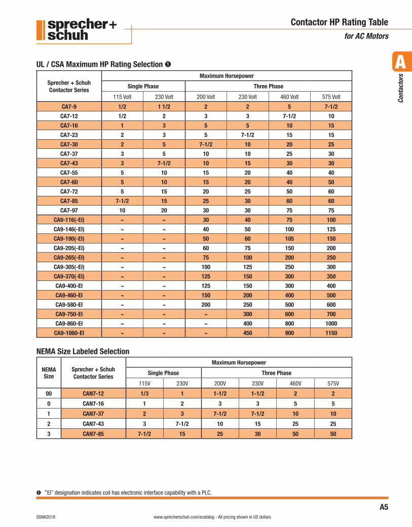
Contactor HP Rating Tablefor AC Motors
➊ “EI” designation indicates coil has electronic interface capability with a PLC.
Sprecher + SchuhContactor Series
Maximum Horsepower
Single Phase Three Phase
115 Volt 230 Volt 200 Volt 230 Volt 460 Volt 575 Volt
CA7-9 1/2 1 1/2 2 2 5 7-1/2
CA7-12 1/2 2 3 3 7-1/2 10
CA7-16 1 3 5 5 10 15
CA7-23 2 3 5 7-1/2 15 15
CA7-30 2 5 7-1/2 10 20 25
CA7-37 3 5 10 10 25 30
CA7-43 3 7-1/2 10 15 30 30
CA7-55 5 10 15 20 40 40
CA7-60 5 10 15 20 40 50
CA7-72 5 15 20 25 50 60
CA7-85 7-1/2 15 25 30 60 60
CA7-97 10 20 30 30 75 75
CA9-116(-EI) ~ ~ 30 40 75 100
CA9-146(-EI) ~ ~ 40 50 100 125
CA9-190(-EI) ~ ~ 50 60 105 150
CA9-205(-EI) ~ ~ 60 75 150 200
CA9-265(-EI) ~ ~ 75 100 200 250
CA9-305(-EI) ~ ~ 100 125 250 300
CA9-370(-EI) ~ ~ 125 150 300 350
CA9-400-EI ~ ~ 125 150 300 400
CA9-460-EI ~ ~ 150 200 400 500
CA9-580-EI ~ ~ 200 250 500 600
CA9-750-EI ~ ~ ~ 300 600 700
CA9-860-EI ~ ~ ~ 400 800 1000
CA9-1060-EI ~ ~ ~ 450 900 1150
NEMA Size Labeled Selection
NEMA Size
Sprecher + SchuhContactor Series
Maximum Horsepower
Single Phase Three Phase
115V 230V 200V 230V 460V 575V
00 CAN7-12 1/3 1 1-1/2 1-1/2 2 2
0 CAN7-16 1 2 3 3 5 5
1 CAN7-37 2 3 7-1/2 7-1/2 10 10
2 CAN7-43 3 7-1/2 10 15 25 25
3 CAN7-85 7-1/2 15 25 30 50 50
UL / CSA Maximum HP Rating Selection ➊

A6visit www.sprecherschuh.com/ecatalog for pricing and the most up to date information SSNA2018
A
Cont
acto
rs
www.sprecherschuh.com/ecatalog - All pricing shown in US dollars
Contactor HP Rating Tablefor DC Motors
Table 50.2Full-load motor-running currents in amperes corresponding to various DC horsepower ratings
Table 50.2 effective April 25, 2003
Horsepower 90 Volts 110-120 Volts 180 Volts 220-240 Volts 500 Volts 550-600 Volts1/10 ~ 2.0 ~ 1.0 ~ ~1/8 ~ 2.2 ~ 1.1 ~ ~1/6 ~ 2.4 ~ 1.2 ~ ~1/4 4.0 3.1 2.0 1.6 ~ ~1/3 5.2 4.1 2.6 2.0 ~ ~1/2 6.8 5.4 3.4 2.7 ~ ~3/4 9.6 7.6 4.8 3.8 ~ 1.61 12.2 9.5 6.1 4.7 ~ 2.0
1-1/2 ~ 13.2 8.3 6.6 ~ 2.72 ~ 17 10.8 8.5 ~ 3.63 ~ 25 16 12.2 ~ 5.25 ~ 40 27 20 ~ 8.3
7-1/2 ~ 58 ~ 29 13.6 12.210 ~ 76 ~ 38 18 1615 ~ 110 ~ 55 27 2420 ~ 148 ~ 72 34 31
DC Motor Ratings
A7visit www.sprecherschuh.com/ecatalog for pricing and the most up to date informationSSNA2018
A
Cont
acto
rs
www.sprecherschuh.com/ecatalog - All pricing shown in US dollars
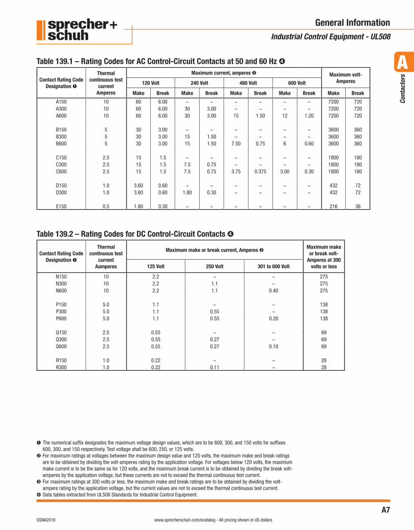
General InformationIndustrial Control Equipment - UL508
Table 139.1 – Rating Codes for AC Control-Circuit Contacts at 50 and 60 Hz ➍
Table 139.2 – Rating Codes for DC Control-Circuit Contacts ➍
Contact Rating Code Designation ➊
Thermal continuous test
current Amperes
Maximum current, amperes ➋ Maximum volt-Amperes120 Volt 240 Volt 480 Volt 600 Volt
Make Break Make Break Make Break Make Break Make Break
A150 10 60 6.00 ~ ~ ~ ~ ~ ~ 7200 720A300 10 60 6.00 30 3.00 ~ ~ ~ ~ 7200 720A600 10 60 6.00 30 3.00 15 1.50 12 1.20 7200 720
B150 5 30 3.00 ~ ~ ~ ~ ~ ~ 3600 360B300 5 30 3.00 15 1.50 ~ ~ ~ ~ 3600 360B600 5 30 3.00 15 1.50 7.50 0.75 6 0.60 3600 360
C150 2.5 15 1.5 ~ ~ ~ ~ ~ ~ 1800 180C300 2.5 15 1.5 7.5 0.75 ~ ~ ~ ~ 1800 180C600 2.5 15 1.5 7.5 0.75 3.75 0.375 3.00 0.30 1800 180
D150 1.0 3.60 0.60 ~ ~ ~ ~ ~ ~ 432 72D300 1.0 3.60 0.60 1.80 0.30 ~ ~ ~ ~ 432 72
E150 0.5 1.80 0.30 ~ ~ ~ ~ ~ ~ 216 36
Contact Rating Code Designation ➊
Thermal continuous test
currentAamperes
Maximum make or break current, Amperes ➌ Maximum make or break volt-
Amperes at 300 volts or less125 Volt 250 Volt 301 to 600 Volt
N150 10 2.2 ~ ~ 275N300 10 2.2 1.1 ~ 275N600 10 2.2 1.1 0.40 275
P150 5.0 1.1 ~ ~ 138P300 5.0 1.1 0.55 ~ 138P600 5.0 1.1 0.55 0.20 138
Q150 2.5 0.55 ~ ~ 69Q300 2.5 0.55 0.27 ~ 69Q600 2.5 0.55 0.27 0.10 69
R150 1.0 0.22 ~ ~ 28R300 1.0 0.22 0.11 ~ 28
➊ The numerical suffix designates the maximum voltage design values, which are to be 600, 300, and 150 volts for suffixes 600, 300, and 150 respectively. Test voltage shall be 600, 250, or 125 volts.
➋ For maximum ratings at voltages between the maximum design value and 120 volts, the maximum make and break ratings are to be obtained by dividing the volt-amperes rating by the application voltage. For voltages below 120 volts, the maximum make current is to be the same as for 120 volts, and the maximum break current is to be obtained by dividing the break volt-amperes by the application voltage, but these currents are not to exceed the thermal continuous test current.
➌ For maximum ratings at 300 volts or less, the maximum make and break ratings are to be obtained by dividing the volt-ampere rating by the application voltage, but the current values are not to exceed the thermal continuous test current.
➍ Data tables extracted from UL508 Standards for Industrial Control Equipment.
A8visit www.sprecherschuh.com/ecatalog for pricing and the most up to date information SSNA2018
A
Cont
acto
rs
www.sprecherschuh.com/ecatalog - All pricing shown in US dollars
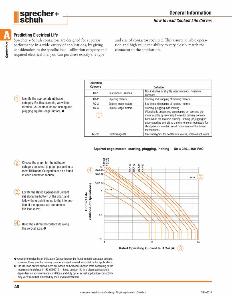
Sprecher + Schuh contactors are designed for superior performance in a wide variety of applications, by giving consideration to the specific load, utilization category and required electrical life, you can purchase exactly the type
and size of contactor required. This assures reliable opera-tion and high value the ability to very closely match the contactor to the application.
General InformationHow to read Contact Life Curves
Predicting Electrical Life
➊ A comprehensive list of Utilization Categories can be found in each contactor section, however, these are the primary categories used in most industrial motor applications.
➋ The life-load curves shown here are based on Sprecher+Schuh tests according to the requirements defined in IEC 60947-4-1. Since contact life in a given application is dependent on environmental conditions and duty cycle, actual application contact life may vary from that indicated by the curves shown here.
➁
➂
➃
➀
Squirrel-cage motors: starting, plugging, inching Ue = 230…460 VAC
.01
0.1
1
10
001011
Con
tact
Life
(Mill
ions
of O
pera
tions
)
CA7-9
CA
7-85
CA
7-72
CA
7-60C
A7-
43C
A7-
37C
A7-
30
CA7-23CA7-16
CA7-12
CA
7-97
AC-4
Rated Operating Current Ie AC-4 [A] ➂
➃➁
➀
Utilization Category Definition
AC-1 Resistance FurnacesNon inductive or slightly inductive loads, Resistive Furnaces
AC-2 Slip-ring motors Starting and stopping of running motors
AC-3 Squirrel-cage motors Starting and stopping of running motorsAC-4 Squirrel-cage motors Starting, plugging, and inching
(Plugging is understood as stopping or reversing the motor rapidly by reversing the motor primary connec-tions while the motor is running. Inching [or jogging] is understood as energizing a motor once or repeatedly for short periods to obtain small movements of the driven mechanism.)
AC-15 Electromagnets Electromagnets for contactors, valves, solenoid actuators
Identify the appropriate utilization category. For this example, we will de-termine CA7 contact life for inching and plugging squirrel-cage motors. ➊
Choose the graph for the utilization category selected. (a graph pertaining to most Utilization Categories can be found in each contactor section.)
Locate the Rated Operational Current (Ie) along the bottom of the chart and follow the graph lines up to the intersec-tion of the appropriate contactor’s life-load curve.
Read the estimated contact life along the vertical axis. ➋
A9visit www.sprecherschuh.com/ecatalog for pricing and the most up to date informationSSNA2018
A
Cont
acto
rs
www.sprecherschuh.com/ecatalog - All pricing shown in US dollars
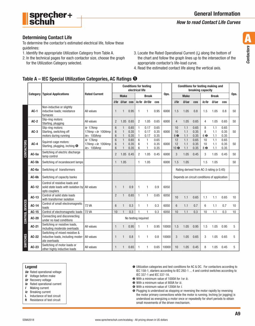
General InformationHow to read Contact Life Curves
Determining Contact Life
Table A – IEC Special Utilization Categories, AC Ratings ➊
➊ Utilization categories and test conditions for AC & DC. For contactors according to IEC 158-1, starters according to IEC 292-1 ... 4 and control switches according to IEC 337-1 and IEC 337-1A.
➋ With a minimum value of 1000A for I or Ic.➌ With a minimum value of 800A for Ic. ➍ With a minimum value of 1200A for I.➎ Plugging is understood as stopping or reversing the motor rapidly by reversing
the motor primary connections while the motor is running. Inching [or jogging] is understood as energizing a motor once or repeatedly for short periods to obtain small movements of the driven mechanism.
LegendUe Rated operational voltageU Voltage before makeUr Recovery voltageIe Rated operational currentI Making currentIc Breaking currentL Inductance of test circuitR Resistance of test circuit
Category Typical Applications Rated Current
Conditions for testing electrical life
Ops.
Conditions for testing making and breaking capacity
Ops.Make Break Make Break
I/Ie U/ue cos Ic/Ie Ur/Ue cos I/Ie U/ue cos Ic/Ie U/ue cos
CONT
ACTO
RS
AC-1Non-inductive or slightly inductive loads; resistance furnaces
All values 1 1 0.95 1 1 0.95 6000 1.5 1.05 0.8 1.5 1.05 0.8 50
AC-2Slip-ring motors: Starting, plugging
All values 2 1.05 0.65 2 1.05 0.65 6000 4 1.05 0.65 4 1.05 0.65 50
AC-3Slip-ring motors: Starting, switching off motors during running
Ie 17Amp17Amp <Ie 100AmpIe> 100Amp
666
111
0.650.350.35
111
0.170.170.17
0.650.350.35
60001010
8 ➋
1.11.11.1
0.650.350.35
88
6 ➌
1.11.11.1
0.650.350.35
50
AC-4Squirrel-cage motors: Starting, plugging, inching ➎
Ie 17Amp17Amp <Ie 100AmpIe> 100Amp
666
111
0.650.350.35
666
111
0.650.350.35
60001212
10 ➍
1.11.11.1
0.650.350.35
1010
8 ➋
1.11.11.1
0.650.350.35
50
AC-5aSwitching of electric discharge lamp control
2 1.05 0.45 2 1.05 0.45 6000 3 1.05 0.45 3 1.05 0.45 50
AC-5b Switching of incandescent lamps 1 1.05 1 1.05 6000 1.5 1.05 1.5 1.05 50
AC-6a Switching of transformers Rating derived from AC-3 rating (x 0.45)
AC-6b Switching of capacity banks Depends on circuit conditions of application
AC-12Control of resistive loads and solid state loads with isolation by opto couplers
All values 1 1 0.9 1 1 0.9 6050
CONT
ROL
DEVI
CES
AC-13Control of solid state loads with transformer isolation
2 1 0.65 1 1 0.65 605010 1.1 0.65 1.1 1.1 0.65 10
AC-14Control of small electromagnetic loads
72 VA 6 1 0.3 1 1 0.3 6050 6 1.1 0.7 6 1.1 0.7 10
AC-15 Control of electromagnetic loads 72 VA 10 1 0.3 1 1 0.3 6050 10 1.1 0.3 10 1.1 0.3 10
AC-20Connecting and disconnecting under no load conditions
No testing required
AC-21Switching or resistive loads, including moderate overloads
All values 1 1 0.95 1 1 0.95 10000 1.5 1.05 0.95 1.5 1.05 0.95 5
SWIT
CHES AC-22
Switching of mixed resistive & inductive loads, including moder-ate overloads
All values 1 1 0.8 1 1 0.8 10000 3 1.05 0.65 3 1.05 0.65 5
AC-23Switching of motor loads or other highly inductive loads
All values 1 1 0.65 1 1 0.65 10000 10 1.05 0.45 8 1.05 0.45 5
To determine the contactor’s estimated electrical life, follow these guidelines:1. Identify the appropriate Utilization Category from Table A.2. In the technical pages for each contactor size, choose the graph
for the Utilization Category selected.
3. Locate the Rated Operational Current (le) along the bottom of the chart and follow the graph lines up to the intersection of the appropriate contactor’s life-load curve.
4. Read the estimated contact life along the vertical axis.
A10visit www.sprecherschuh.com/ecatalog for pricing and the most up to date information SSNA2018
A
Cont
acto
rs
www.sprecherschuh.com/ecatalog - All pricing shown in US dollars
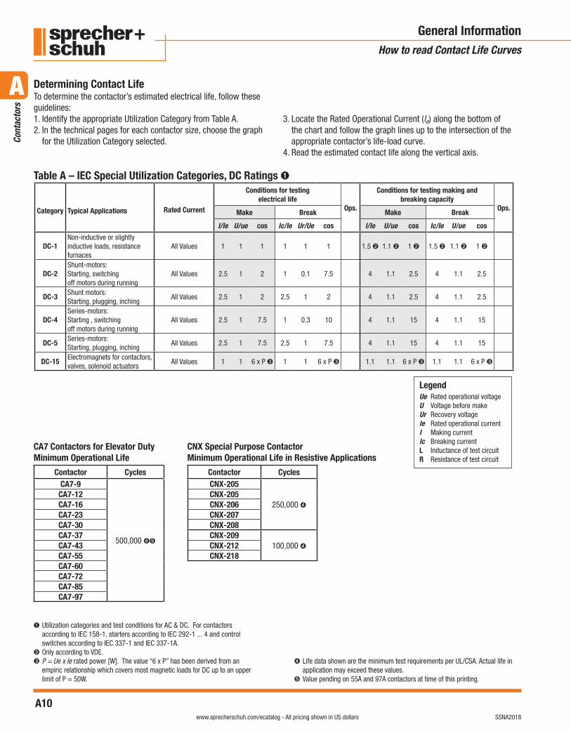
General InformationHow to read Contact Life Curves
Table A – IEC Special Utilization Categories, DC Ratings ➊
➊ Utilization categories and test conditions for AC & DC. For contactors according to IEC 158-1, starters according to IEC 292-1 ... 4 and control switches according to IEC 337-1 and IEC 337-1A.
➋ Only according to VDE.➌ P = Ue x Ie rated power [W]. The value “6 x P” has been derived from an
empiric relationship which covers most magnetic loads for DC up to an upper limit of P = 50W.
➍ Life data shown are the minimum test requirements per UL/CSA. Actual life in application may exceed these values.
➎ Value pending on 55A and 97A contactors at time of this printing.
Determining Contact LifeTo determine the contactor’s estimated electrical life, follow these guidelines:1. Identify the appropriate Utilization Category from Table A.2. In the technical pages for each contactor size, choose the graph
for the Utilization Category selected.
3. Locate the Rated Operational Current (le) along the bottom of the chart and follow the graph lines up to the intersection of the appropriate contactor’s life-load curve.
4. Read the estimated contact life along the vertical axis.
LegendUe Rated operational voltageU Voltage before makeUr Recovery voltageIe Rated operational currentI Making currentIc Breaking currentL Inductance of test circuitR Resistance of test circuit
Category Typical Applications Rated Current
Conditions for testing electrical life
Ops.
Conditions for testing making and breaking capacity
Ops.Make Break Make Break
I/Ie U/ue cos Ic/Ie Ur/Ue cos I/Ie U/ue cos Ic/Ie U/ue cos
DC-1Non-inductive or slightly inductive loads, resistance furnaces
All Values 1 1 1 1 1 1 1.5 ➋ 1.1 ➋ 1 ➋ 1.5 ➋ 1.1 ➋ 1 ➋
DC-2Shunt-motors: Starting, switchingoff motors during running
All Values 2.5 1 2 1 0.1 7.5 4 1.1 2.5 4 1.1 2.5
DC-3Shunt motors: Starting, plugging, inching
All Values 2.5 1 2 2.5 1 2 4 1.1 2.5 4 1.1 2.5
DC-4Series-motors: Starting , switchingoff motors during running
All Values 2.5 1 7.5 1 0.3 10 4 1.1 15 4 1.1 15
DC-5Series-motors: Starting, plugging, inching
All Values 2.5 1 7.5 2.5 1 7.5 4 1.1 15 4 1.1 15
DC-15Electromagnets for contactors, valves, solenoid actuators
All Values 1 1 6 x P ➌ 1 1 6 x P ➌ 1.1 1.1 6 x P ➌ 1.1 1.1 6 x P ➌
CA7 Contactors for Elevator Duty Minimum Operational Life
Contactor CyclesCA7-9
500,000 ➍➎
CA7-12CA7-16CA7-23CA7-30CA7-37CA7-43CA7-55CA7-60CA7-72CA7-85CA7-97
CNX Special Purpose ContactorMinimum Operational Life in Resistive Applications
Contactor CyclesCNX-205
250,000 ➍CNX-205CNX-206CNX-207CNX-208CNX-209
100,000 ➍CNX-212CNX-218
A11visit www.sprecherschuh.com/ecatalog for pricing and the most up to date informationSSNA2018
A
Cont
acto
rs
www.sprecherschuh.com/ecatalog - All pricing shown in US dollars
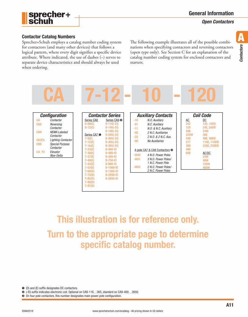
CA 7-12 - 10 - 120
General InformationOpen Contactors
➊ (D) and (E) suffix designates DC contactors.➋ (-EI) suffix indicates electronic coil. Optional on CA9-116…365, standard on CA9-400…2650.➌ On four pole contactors, this number designates main power pole configuration.
Coil CodeAC 24Z120208220W240277380480600
DC12E, 12DD24E, 24DD24W36E48E, 48DD110E, 110DD220E, 220DD
AC/DC24W48W120W480W
Contactor Catalog NumbersSprecher+Schuh employs a catalog number coding system for contactors (and many other devices) that follows a logical pattern, where every digit signifies a specific device attribute. Where indicated, the use of dashes (–) serves to separate device characteristics and should always be used when ordering.
The following example illustrates all of the possible combi-nations when specifying contactors and reversing contactors (open type only). See Section C for an explanation of the catalog number coding system for enclosed contactors and starters.
This illustration is for reference only.
Turn to the appropriate page to determinespecific catalog number.
ConfigurationCA ContactorCAU Reversing
ContactorCAN NEMA Labeled
ContactorCA(V)L Lighting ContactorCNX Special Purpose
ContactorCA_Y2 Elevator
Wye-Delta
Contactor SeriesSeries CA8 8-09(C)8-12(C)
Series CA7 ➊7-9(E)7-12(E)7-16(E)7-23(E)7-30(E)7-37(E)7-40(E)7-43(E)7-55(E)7-60(D)7-72(D)7-85(D)7-90(D)7-97(D)
Series CA9 ➋9-116(-EI)9-146(-EI)9-190(-EI)9-205(-EI)9-265(-EI)9-305(-EI)9-365(-EI)9-400-EI9-460-EI9-580-EI9-750-EI9-860-EI9-1060-EI9-1260-EI9-2050-EI9-2650-EI
Auxiliary Contacts-10 N.O. Auxiliary-01 N.C. Auxiliary-11 N.O. & N.C. Auxiliary-02 2 N.C. Auxiliaries-22 2 N.O. & 2 N.C. Aux.-00 No Auxiliaries
4-pole CA7 & CA8 Contactors ➌
-M40 4 N.O. Power Poles-M31 3 N.O. Power Poles/
1 N.C. Power Pole-M22 2 N.O. Power Poles/
2 N.C. Power Poles
A12visit www.sprecherschuh.com/ecatalog for pricing and the most up to date information SSNA2018
A
Cont
acto
rs
www.sprecherschuh.com/ecatalog - All pricing shown in US dollars
Notes
General Information