gebrauchs- und montageanleitung operating and … · produktdatenblatt nach vorgabe der eu...
TRANSCRIPT
05.17
Gebrauchs- und Montageanleitung Operating and installation instructions
Warmwasserspeicher S 50/80/100
Water storage heater S 50/80/100
de > 2
en > 11
S 50 / S 80 / S 100
2
Inhalt
1. Sicherheitshinweise . . . . . . . . . . . . . . . . . . . . . . . . . . . . . . . . . . . . . . . . . . . . . . . . . . . . . . . . . . . . 3
2. Legionellenprävention . . . . . . . . . . . . . . . . . . . . . . . . . . . . . . . . . . . . . . . . . . . . . . . . . . . . . . . . . . 5
Informationen gemäß europäischer Norm CEN/TR 16355. . . . . . . . . . . . . . . . . . . . . . . . . . . . . 5
Allgemeine Empfehlungen . . . . . . . . . . . . . . . . . . . . . . . . . . . . . . . . . . . . . . . . . . . . . . . . . . . . . . 5
Typen von Warmwasseranlagen . . . . . . . . . . . . . . . . . . . . . . . . . . . . . . . . . . . . . . . . . . . . . . . . . . 5
3. Übersicht . . . . . . . . . . . . . . . . . . . . . . . . . . . . . . . . . . . . . . . . . . . . . . . . . . . . . . . . . . . . . . . . . . . . . 6
4. Technische Daten . . . . . . . . . . . . . . . . . . . . . . . . . . . . . . . . . . . . . . . . . . . . . . . . . . . . . . . . . . . . . . 6
5. Installation . . . . . . . . . . . . . . . . . . . . . . . . . . . . . . . . . . . . . . . . . . . . . . . . . . . . . . . . . . . . . . . . . . . 7
Gerät montieren . . . . . . . . . . . . . . . . . . . . . . . . . . . . . . . . . . . . . . . . . . . . . . . . . . . . . . . . . . . . . . . 7
Wasseranschluss. . . . . . . . . . . . . . . . . . . . . . . . . . . . . . . . . . . . . . . . . . . . . . . . . . . . . . . . . . . . . . . 7
6. Inbetriebnahme . . . . . . . . . . . . . . . . . . . . . . . . . . . . . . . . . . . . . . . . . . . . . . . . . . . . . . . . . . . . . . . 8
Erstinbetriebnahme . . . . . . . . . . . . . . . . . . . . . . . . . . . . . . . . . . . . . . . . . . . . . . . . . . . . . . . . . . . . 8
Geschlossener Betrieb . . . . . . . . . . . . . . . . . . . . . . . . . . . . . . . . . . . . . . . . . . . . . . . . . . . . . . . . . . 8
Offener Betrieb . . . . . . . . . . . . . . . . . . . . . . . . . . . . . . . . . . . . . . . . . . . . . . . . . . . . . . . . . . . . . . . . 8
Elektroanschluss . . . . . . . . . . . . . . . . . . . . . . . . . . . . . . . . . . . . . . . . . . . . . . . . . . . . . . . . . . . . . . . 8
7. Bedienung. . . . . . . . . . . . . . . . . . . . . . . . . . . . . . . . . . . . . . . . . . . . . . . . . . . . . . . . . . . . . . . . . . . . 9
Einstellung der Betriebstemperatur . . . . . . . . . . . . . . . . . . . . . . . . . . . . . . . . . . . . . . . . . . . . . . . 9
8. Wartung, Reinigung und Pflege . . . . . . . . . . . . . . . . . . . . . . . . . . . . . . . . . . . . . . . . . . . . . . . . . . 9
Wartungsvorschriften . . . . . . . . . . . . . . . . . . . . . . . . . . . . . . . . . . . . . . . . . . . . . . . . . . . . . . . . . . 9
9. Selbsthilfe bei Problemen und Kundendienst . . . . . . . . . . . . . . . . . . . . . . . . . . . . . . . . . . . . . . 10
10. Umwelt und Recycling . . . . . . . . . . . . . . . . . . . . . . . . . . . . . . . . . . . . . . . . . . . . . . . . . . . . . . . . 10
11. Produktdatenblatt nach Vorgabe der EU Verordnungen - 812/2013 814/2013. . . . . . . . 20
12. Abbildungen. . . . . . . . . . . . . . . . . . . . . . . . . . . . . . . . . . . . . . . . . . . . . . . . . . . . . . . . . . . . . . . . . . I
CLAGE
3
1. Sicherheitshinweise
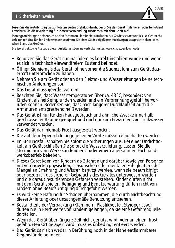
Lesen Sie diese Anleitung bis zur letzten Seite sorgfältig durch, bevor Sie das Gerät installieren oder benutzen! Bewahren Sie diese Anleitung für spätere Verwendung zusammen mit dem Gerät auf!
Montageanleitungen richten sich an den Fachmann, der für die Installation des Gerätes verantwortlich ist. Gebrauchs-anleitungen sind für den Endanwender bestimmt. Die dem Gerät beigefügten Anleitungen entsprechen dem techni-schen Stand des Gerätes.
Die jeweils aktuelle Ausgabe dieser Anleitung ist online verfügbar unter: www.clage.de/downloads
• Benutzen Sie das Gerät nur, nachdem es korrekt instal liert wurde und wenn es sich in technisch ein wand freiem Zustand befindet.
• Öffnen Sie niemals das Gerät, ohne vorher die Strom zufuhr zum Gerät dau-erhaft unterbrochen zu haben.
• Nehmen Sie am Gerät oder an den Elektro- und Wasser leitungen keine tech-nischen Änderungen vor.
• Das Gerät muss geerdet werden. • Beachten Sie, dass Wasser tempe raturen über ca. 43 °C, besonders von
Kindern, als heiß empfunden werden und ein Verbrennungs gefühl hervor-rufen können. Bedenken Sie, dass nach längerer Durch laufzeit auch die Armaturen entsprechend heiß werden.
• Das Gerät ist nur für den Haus gebrauch und ähnliche Zwecke innerhalb geschlossener Räume geeignet und darf nur zum Erwärmen von Trinkwasser verwendet werden.
• Das Gerät darf niemals Frost ausgesetzt werden. • Die auf dem Typenschild angegebenen Werte müssen eingehalten werden.• Im Störungsfall schalten Sie sofort die Sicherungen aus. Bei einer Undichtig-
keit am Gerät schließen Sie sofort die Wasser zuleitung. Lassen Sie die Störung nur vom Werks kundendienst oder einem anerkannten Fachhand-werks betrieb beheben.
• Dieses Gerät kann von Kindern ab 3 Jahren und darüber sowie von Personen mit verringerten physischen, sensorischen oder mentalen Fähigkeiten oder Mangel an Erfahrung und Wissen benutzt werden, wenn sie beaufsichtigt oder bezüglich des sicheren Gebrauchs des Gerätes unterwiesen wurden und die daraus resultierenden Gefahren verstehen. Kinder dürfen nicht mit dem Gerät spielen. Reinigung und Benutzerwartung dürfen nicht von Kindern ohne Beaufsichtigung durchgeführt werden.
• Es wird keine Haftung für Schäden übernommen, die durch Nichtbeachtung dieser Anleitung oder unsachgemäße Benutzung entstehen.
• Bestandteile der Verpackung (Klammern, Plastikbeutel, Styropor usw.) dürfen nie in Reichweite von Kindern gelangen, da sie eine Gefahrenquelle darstellen.
• Wenn das Gerät über längere Zeit nicht genutzt wird, oder an einem frost-gefährdeten Ort gelagert wird, muss es unbedingt entleert werden.
• Das Gerät darf sich weder in Berührung noch in der Nähe entflammbarer Gegenstände befinden.
S 50 / S 80 / S 100
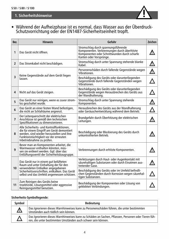
Symbol Bedeutung
Das Ignorieren dieses Warnhinweises kann zu Personenschäden führen, die unter bestimmten Umständen auch tödlich sein können.
Das Ignorieren dieses Warnhinweises kann zu Schäden an Sachen, Pflanzen, Personen oder Tieren füh-ren, die unter bestimmten Umständen auch schwer sein können.
Bez. Hinweis Gefahr Zeichen
1 Das Gerät nicht öffnen.
Stromschlag durch span nungsführende Komponenten. Verbrennungen durch überhitzte Komponenten oder Schnittwunden durch scharfe Kanten oder Vorsprünge.
2 Das Stromkabel nicht beschädigen. Stromschlag durch unter Spannung stehende blanke Kabel.
3 Keine Gegenstände auf dem Gerät liegen lassen.
Personenschäden durch fallende Gegenstände wegen Vibrationen.
Beschädigung des Geräts oder darunterliegenden Gegenstände durch fallende Gegenständen wegen Vibrationen.
4 Nicht auf das Gerät steigen.Beschädigung des Geräts oder darunterliegenden Gegenstände wegen Herausbrechen des Geräts aus der Wandhalterung.
5 Das Gerät nur reinigen, wenn es zuvor strom-los geschaltet wurde.
Stromschlag durch unter Spannung stehende Komponenten.
6 Das Gerät an einer festen Wand befestigen, die nicht an Schlafräume angrenzt.
Herausbrechen des Geräts aus der Wandhalterung oder Geräuschentwicklung während dem Betrieb.
7Der Leiterquerschnitt der elektrischen Anschlüsse ist gemäß den technischen Spezifikationen zu dimensionieren.
Brandgefahr durch Überhitzung der elektrischen Leitungen.
8
Alle Sicherheits- und Kontrollfunktionen, die für einem Eingriff am Gerät demontiert werden, sind wieder herzustellen und ihre Funktionstüchtigkeit vor der erneuten Inbetriebnahme zu prüfen.
Beschädigung oder Blockierung des Geräts durch unkontrollierten Betrieb.
9
Bevor man an Komponenten arbeitet, die Warmwasser enthalten könnten, müs-sen sie entleert werden. Ggf. über das Entlüftungsventil der Sicherheitsbaugruppe.
Verbrennungen durch erhitzte Komponenten.
10
Das Gerät nur in einem gut belüfteten Raum und unter Einhaltung der für den verwendeten Entkalker angegebenen Sicherheitsvorschriften, entkalken. Das Gerät selbst und das Umfeld angemessen schützen.
Verletzungen durch Haut- oder Augenkontakt mit säurehaltigen Substanzen oder durch Einatmen aus-tretender Gase.
Beschädigung des Geräts oder im Umfeld befindli-chen Gegenständen durch Korrosion wegen säurehal-tigen Substanzen.
11Zum Reinigen des Geräts keine Insektizide, Lösungsmittel oder aggressive Reinigungsmittel benutzen.
Beschädigung der Komponenten oder Lösung von geklebten Verbindungen.
4
Sicherheits-Symbollegende:
1. Sicherheitshinweise
• Während der Aufheizphase ist es normal, dass Wasser aus der Überdruck-Schutzvorrichtung oder der EN1487-Sicherheitseinheit tropft.
CLAGE
Kaltwasser und Warmwasser separat Kaltwasser und Warmwasser gemischt
Keine Speicherung Speicherung Keine Speicherung über den Mischventilen
Speicherung über den Mischventilen
Keine Speicherung über den Mischventilen
Kein Warmwasserumlauf
Mit Warmwasserumlauf
Kein Mischwasserumlauf
Mit Mischwasserumlauf
Kein Mischwasserumlauf
Mit Mischwasserumlauf
Kein Mischwasserumlauf
Mit Mischwasserumlauf
Kein Mischwasserumlauf
Mit Mischwasserumlauf
Bez. in Anhang C C.1 C.2 C.3 C.4 C.5 C.6 C.7 C.8 C.9 C.10Temperatur ≥ 50 °C e in
Warmwasserspeicher a
≥ 50 °C e Wärmedesinfektion d
Wärmedesinfektion d
inWarmwasser
speicher a
≥ 50 °C e
Wärmedesinfektion d
Wärmedesinfektion d
Wärmedesinfektion d
Stauung ≤ 3 l b ≤ 3 l b ≤ 3 l b ≤ 3 l b ≤ 3 l b
Sediment entfernen c entfernen c entfernen c entfernen c
a Temperatur ≥ 55 °C den ganzen Tag oder wenigstens 1 Std pro Tag ≥ 60 °C.b Wasservolumen in den Rohrleitungen zwischen dem Umlaufsystem und dem Hahn mit größerem Abstand im Verhältnis zum System.c Sediment aus dem Warmwasserspeicher gemäß lokalen Bedingungen entfernen, jedenfalls mindestens einmal pro Jahr.d Wärmedesinfektion 20 Minuten lang bei einer Temperatur von 60 °C, 10 Minuten lang bei 65 °C oder 5 Minuten lang bei 70 °C an allen Entnahmestellen,
mindestens einmal pro Woche. e Die Wassertemperatur im Umlaufring darf nicht höher als 50 °C sein. Nicht erforderlich.
5
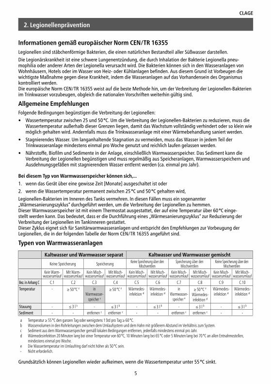
Informationen gemäß europäischer Norm CEN/TR 16355Legionellen sind stäbchenförmige Bakterien, die einen natürlichen Bestandteil aller Süßwasser darstellen.
Die Legionärskrankheit ist eine schwere Lungenentzündung, die durch Inhalation der Bakterie Legionella pneu-mophilia oder anderer Arten der Legionella verursacht wird. Die Bakterien können sich in den Wasseranlagen von Wohnhäusern, Hotels oder im Wasser von Heiz- oder Kühlanlagen befinden. Aus diesem Grund ist Vorbeugen die wichtigste Maßnahme gegen diese Krankheit, indem die Wasseranlagen auf das Vorhandensein des Organismus kontrolliert werden. Die europäische Norm CEN/TR 16355 weist auf die beste Methode hin, um der Verbreitung der Legionellen-Bakterien im Trinkwasser vorzubeugen, obgleich die nationalen Vorschriften weiterhin gültig sind.
Allgemeine Empfehlungen Folgende Bedingungen begünstigen die Verbreitung der Legionellen:
• Wassertemperatur zwischen 25 und 50 °C. Um die Verbreitung der Legionellen-Bakterien zu reduzieren, muss die Wassertemperatur außerhalb dieser Grenzen liegen, damit das Wachstum vollständig verhindert oder so klein wie möglich gehalten wird. Andernfalls muss die Trinkwasseranlage mit einer Wärmebehandlung saniert werden.
• Stagnierendes Wasser. Um langanhaltende Stagnation zu vermeiden, muss das Wasser in jedem Teil der Trinkwasseranlage mindestens einmal pro Woche genutzt und reichlich laufen gelassen werden.
• Nährstoffe, Biofilm und Sedimente in der Anlage, einschließlich Warmwasserspeicher. Das Sediment kann die Verbreitung der Legionellen begünstigen und muss regelmäßig aus Speicheranlagen, Warmwasserspeichern und Ausdehnungsgefäßen mit stagnierendem Wasser entfernt werden (ca. einmal pro Jahr).
Bei diesem Typ von Warmwasserspeicher können sich,...
1. wenn das Gerät über eine gewisse Zeit [Monate] ausgeschaltet ist oder
2. wenn die Wassertemperatur permanent zwischen 25 °C und 50 °C gehalten wird,
Legionellen-Bakterien im Inneren des Tanks vermehren. In diesen Fällen muss ein sogenannter „Wärmesanierungszyklus“ durchgeführt werden, um die Verbreitung der Legionellen zu hemmen. Dieser Warmwasserspeicher ist mit einem Thermostat ausgestattet, der auf eine Temperatur über 60 °C einge-stellt werden kann. Das bedeutet, dass er die Durchführung eines „Wärmesanierungszyklus“ zur Reduzierung der Verbreitung der Legionellen im Tankinneren gestattet. Dieser Zyklus eignet sich für Sanitärwarmwasseranlagen und entspricht den Empfehlungen zur Vorbeugung der Legionellen, die in der folgenden Tabelle der Norm CEN/TR 16355 angeführt sind.
Typen von Warmwasseranlagen
2. Legionellenprävention
Grundsätzlich können Legionellen wieder aufkeimen, wenn die Wassertemperatur unter 55 °C sinkt.
S 50 / S 80 / S 100
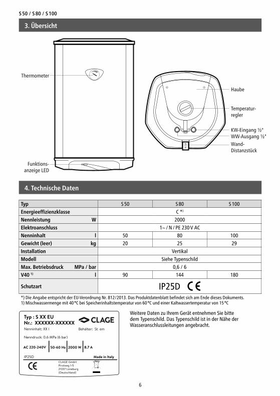
Typ S 50 S 80 S 100
Energieeffizienzklasse C *)
Nennleistung W 2000
Elektroanschluss 1~ / N / PE 230 V AC
Nenninhalt l 50 80 100
Gewicht (leer) kg 20 25 29
Installation Vertikal
Modell Siehe Typenschild
Max. Betriebsdruck MPa / bar 0,6 / 6
V40 1) l 90 144 180
Schutzart IP25D*) Die Angabe entspricht der EU-Verordnung Nr. 812/2013. Das Produktdatenblatt befindet sich am Ende dieses Dokuments.1) Mischwassermenge mit 40 °C bei Speicherinhaltstemperatur von 60 °C und einer Kaltwassertemperatur von 15 °C
6
4. Technische Daten
Typ : S XX EUNr.: XXXXXX-XXXXXXNenninhalt: XX l
IP25DCLAGE GmbHPirolweg 1-521337 Lüneburg(Deutschland)
Nenndruck: 0.6 MPa (6 bar)
AC 220-240V 50-60 Hz 2000 W 8.7 A
Made in Italy
Behälter: St em
Weitere Daten zu Ihrem Gerät entnehmen Sie bitte dem Typenschild. Das Typenschild ist in der Nähe der Wasseranschlussleitungen angebracht.
3. Übersicht
Thermometer
Funktions-anzeige LED
Wand-Distanzstück
WW-Ausgang ½"KW-Eingang ½"
Temperatur-regler
Haube

CLAGE
7
ACHTUNG! In den Ländern, in denen die europäische Norm EN 1487 angenommen wurde, muss eine normge-rechte Vorrichtung mit einen maximalen Druck von 0,7 MPa (7 bar) installiert werden und mindestens folgende Teile umfassen: einen Absperrhahn, ein Rückschlagventil, eine Kontrollvorrichtung des Rückschlagventils, ein Sicherheitsventil und eine Unterbrechungsvorrichtung der Wasserlast. Das mit dem Gerät mitgelieferte Überdruckventil ist in diesen Ländern nicht zugelassen!Dieses Gerät ist dazu bestimmt, entsprechend der geltenden Vorschriften ausschließlich in einem Innenraum installiert zu werden. Dabei sind folgende Hinweise bezüglich des Umfeldes am Installationsort zu beachten:
Bei Wänden aus Ziegelsteinen oder Hohlblocksteinen, Zwischenwänden von beschränkter Stabilität oder Mauerwerk, das nicht dem angegebenen Mauerwerk entspricht, ist vor der Installation die Stabilität der Wände und Mauern, an denen das Gerät installiert wird, zu überprüfen.
Gerät montierenDie Wandbefestigungshaken müssen derart beschaffen sein, dass sie das dreifache Gewicht des vollen Warmwassergeräts tragen können. Wir empfehlen, die mitgelieferten Haken zu verwenden.
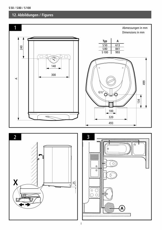
1. Markieren Sie die Befestigungspunkte des Warmwasserspeichers gemäß der Maße in Abb. 1 und bohren die Löcher.
2. Befestigen Sie die Haken an der Wand.
3. Hängen Sie das Warmwassergerät in die Haken ein.
4. Justieren Sie das Warmwassergerät mit dem regulierbaren Wand-Distanzstück „X“ lotrecht (Abb. 2).
Die lokalen Vorschriften können Einschränkungen für die Installation im Badezimmer vorsehen. Halten Sie sich stets an die in den geltenden Vorschriften angegebenen Mindestabstände. Der Warmwasserspeicher ist so nah wie möglich an den Zapfstellen zu installieren, sodass unnötiger Wärmeverlust durch lange Rohrleitungen vermieden wird („A“ in Abb. 3).
Zur Wartung des Gerätes ist ein Freiraum von mindestens 50 cm unterhalb des Speichers vorzusehen, um an die Elektroteile gelangen zu können.
WasseranschlussVor dem Wasseranschluss sind die Wasserleitungen gründlich durchzuspülen, damit eventuelle Rückstände oder Verschmutzungen, welche die Funktionstüchtigkeit des Warmwasserspeichers beeinträchtigen könnten, entfernt werden.
Vergewissern Sie sich, dass die Leitungen (Wasserzufuhr und -entnahme) mit Rohren oder Verbindungsstücken angeschlossen werden, die nicht nur dem Betriebsdruck sondern auch den hohen Wassertemperaturen des Warmwasserspeichers, die im Normalfall 80 °C übersteigen können, standhalten.
Wird der Ablauf des Sicherheitsventils nicht direkt über dem Ablauftrichter angeordnet, muss er an einen Schlauch mit kontinuierlicher Neigung und an einer frostsicheren Stelle angeschlossen werden.
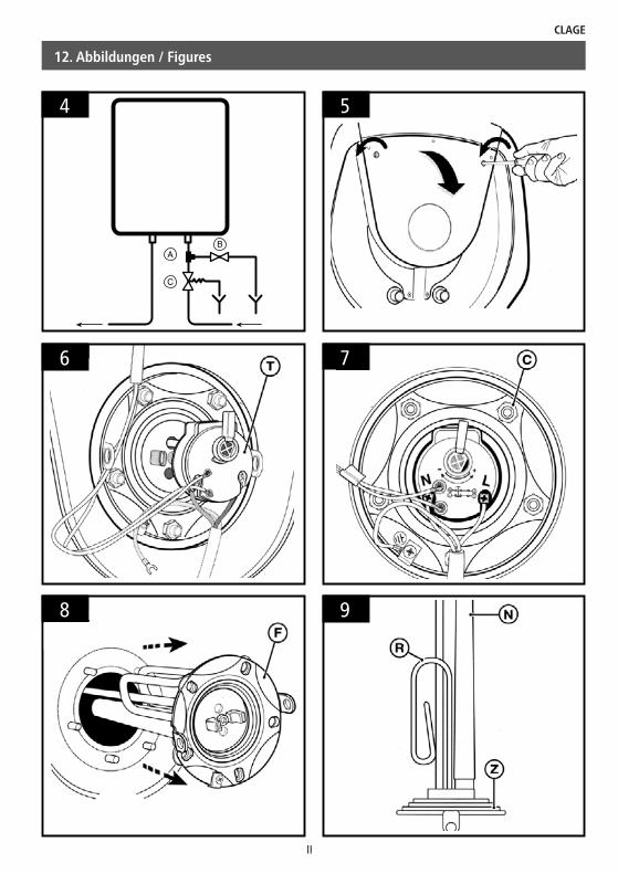
Für die leichtere Entleerung des Speichers empfehlen wir einen Anschluss nach Abb. 4. Verbinden Sie ein T-Stück „A“ mit dem Kaltwasserzulauf des Speichers und am seitlichen Teil wird ein Ablaufventil „B“ installiert, welches ausschließlich mit Werkzeug geöffnet werden kann. Die Sicherheitsbaugruppe „C“ muss dann mit dem anderen Anschluss des T-Stückes verbunden werden.
Bei besonders hartem Wasser (>14 °dH) steigert sich die Kalkablagerung im Inneren des Gerätes, was Einbußen der Funktionstüchtigkeit des Geräts und eine Beschädigung des Heizelementes zur Folge haben kann. Das Gerät muss ent-
Zu beachten sind:
• VDE 0100
• EN 806
• Bestimmungen der örtlichen Energie- und Wasser versorgungs unternehmen
• Technische Daten und Angaben auf dem Typenschild
• Die ausschließliche Verwendung von geeignetem und unbeschädigtem Werkzeug• Das Gerät muss vor dem Elektroanschluss an die Wasserversorgung angeschlossen und gefüllt werden
• Installation und Inbetriebnahme des Warmwasserspeichers dürfen nur von einem anerkannten Fachhand-werksbetrieb durchgeführt werden
• Der Warmwasserspeicher darf keiner direkten Sonneneinstrahlung ausgesetzt sein
• Das Gerät darf nicht an einer Zirkulationsleitung angeschlossen werden
5. Installation
S 50 / S 80 / S 100
8
sprechend regelmäßig entkalkt werden. Um Kalkablagerungen zu verringern, können Sie das Wasser im Kaltwassereinlauf mit einer entsprechenden trinkwassergeeigneten Vorrichtung enthärten.
Für die korrekte Funktionsweise des galvanischen Schutzsystemes ist es allerdings erforderlich, dass das Wasser nicht unter einen Wert von 8,4 °dH enthärtet wird.
Ab Wasserhärten unter 6,7 °dH ist eine Nutzung des Gerätes nicht mehr zulässig!
Geschlossener BetriebInstallieren Sie das Gerät nahe der Zapfstelle, bei der das meiste Warmwasser entnommen wird.
Es ist immer eine Baumuster geprüfte Sicherheitsventil-Kombination einzubauen. Bei einem Wasserdruck größer als 0,48 MPa (4,8 bar) ist zusätzlich ein Druckminderer-Ventil einzubauen und entsprechend einzustellen. Zwischen den Sicherheitsbaugruppen und dem Speicher darf kein Absperrventil montiert werden.
Das mit dem Gerät gelieferte Überdruckventil ist in Ländern, die die Norm EN 1487 angenommen haben, nicht zugelassen!
Der Ablauf des Sicherheitsventils muss immer offen sein. Die Sicherheitsventil-Kombination muss für geschlossenen Betrieb zugelassen sein (Baumuster geprüft).
Anmerkung: Nach dem Energie-Einspargesetz muss die Temperatur bei Warmwasser-Leitungen, die eine Länge von 5 m überschreiten, auf 60 °C begrenzt werden.
Offener BetriebFür drucklose Geräte ist eine geeignete Mischbatterie zu installieren. Der Auslauf der Mischbatterie muss immer offen sein. Verwenden Sie ausschließlich CLAGE Strahlregler für drucklose Speicher. Am Kaltwasser-Zulauf ist ein Rückflussverhinderer zu installieren.
ElektroanschlussBauliche Voraussetzungen
• Das Gerät muss über die Anschlussleitung an eine vorschriftsmäßig installierte Schutzkontakt-Steckdose angeschlos-sen werden. Mehrfachstecker dürfen nicht verwendet werden!
• Die Anschlussleitung muss sich in einem einwandfreien Zustand befinden und darf bei Beschädigung nur durch einen Fachmann und nur durch originale Ersatzteile ausgetauscht werden.
• Installationsseitig ist eine allpolige Trennvorrichtung mit einer Kontaktöffnungsweite von mindestens 3 mm pro Pol vorzusehen (z.B. über Sicherungen).
• Zur Absicherung des Gerätes ist ein Sicherungselement für Leitungsschutz mit einem dem Gerätenennstrom ange-passten Auslösestrom zu montieren
1. Schalten Sie vor dem Elektroanschluss die Zuleitungen zum Gerät, z. B. über Sicherungen, spannungsfrei und sichern Sie diese gegen unbeabsichtigtes Wiedereinschalten.
2. Stecken Sie den Schutzkontaktstecker in die Steckdose.
Bitte überprüfen Sie, ob die elektrische Hausinstallation für die vom Gerät bezogene maximale Leistung ausgelegt ist (Daten vom Typenschild beachten).
5. Installation
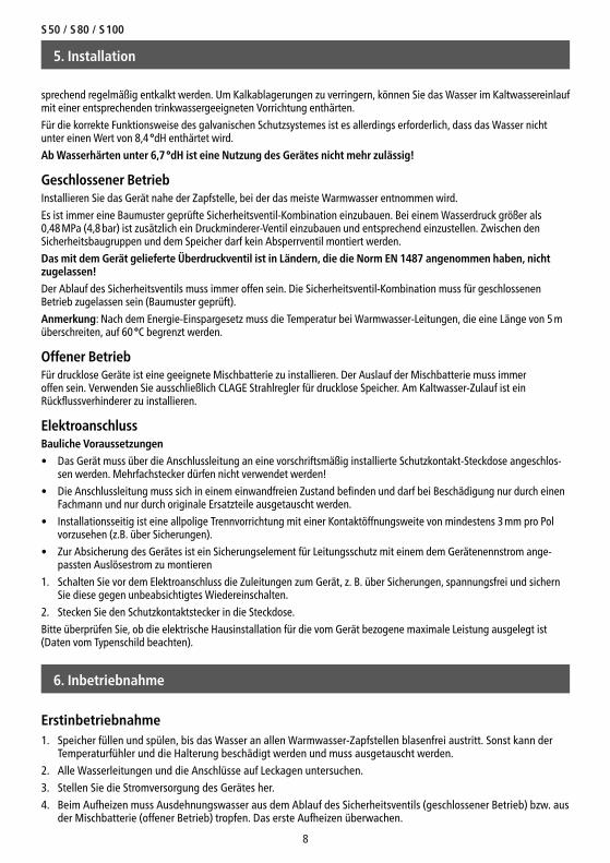
Erstinbetriebnahme1. Speicher füllen und spülen, bis das Wasser an allen Warmwasser-Zapfstellen blasenfrei austritt. Sonst kann der
Temperaturfühler und die Halterung beschädigt werden und muss ausgetauscht werden.
2. Alle Wasserleitungen und die Anschlüsse auf Leckagen untersuchen.
3. Stellen Sie die Stromversorgung des Gerätes her.
4. Beim Aufheizen muss Ausdehnungswasser aus dem Ablauf des Sicherheitsventils (geschlossener Betrieb) bzw. aus der Mischbatterie (offener Betrieb) tropfen. Das erste Aufheizen überwachen.
6. Inbetriebnahme
CLAGE
9
Wartungsvorschriften Vor jedem Wartungseingriff oder vor dem Einbau eines neuen Bauteils ist das Gerät von der Stromversorgung zu trennen. Falls notwendig, ist der Warmwasserspeicher zu entleeren.
Nach jeweils einem Betriebsjahr sind folgende Schritte durchzuführen:
• Entleeren Sie das Gerät (Wasserzulauf sperren, Warmwasserarmaturen öffnen und über Sicherheitsventil oder ggf. installiertem Ablaufventil entleeren) und entfernen Sie das Heizelement.
• Entfernen Sie regelmäßig (min. alle 2 Jahre) sämtliche Kalkablagerungen an dem Heizelement „R“ (Abb. 9); falls Sie dazu keine für diesen Zweck geeigneten Säuren verwenden möchten, kann die Kalkkruste auch mit Hilfe von nicht metallenen Gegenständen abgekratzt werden. Dabei ist darauf zu achten, dass das Schutzgehäuse des Heizelementes nicht beschädigt wird. Für den Ausbau des Heizelementes / der Anode gehen Sie wie folgt vor:
1. Nachdem Sie den Speicher entleert und die Stromversorgung getrennt haben, öffnen Sie die Gerätehaube (Abb.5).
2. Entfernen Sie den Thermostaten „T“ (Abb. 6). Muss der Thermostat ersetzt werden, ist er vom Zuleitungskabel abzutrennen und aus seinem Sitz herauszuziehen.
3. Schrauben Sie die fünf Sechskantschrauben „C“ (Abb. 7) hinaus und nehmen Sie den Flansch „F“ (Abb. 8) ab. Am Flansch ist das Heizelement „R“ und die Anode „N“ (Abb. 9) gekoppelt.
• Die Polung der elektrischen Anschlüsse (Abb. 7) muss bei Wiederzusammenbau eingehalten werden.
• Es wird empfohlen, die Dichtung „Z“ (Abb. 9) nach jedem Entfernen des Heizelementes zu ersetzen.
• Überprüfen Sie den Zustand der Anode „N“ (Abb. 9); diese verschleißt mehr oder weniger stark je nach entnomme-ner Wasser menge und schützt den Kessel vor Korrosion.
• Die Anode ist auszutauschen, wenn ihr Gesamtvolumen im Vergleich zu ihrem ursprünglichen Volumen, um mehr als 50% abgenommen hat, mindestens aber alle zwei Jahre.
• Bei erneuter Montage des 5-Schraubenflansches „F“ ist darauf zu achten, dass das Anziehen der Muttern über Kreuz erfolgt.
• Prüfen sie regelmäßig (mindestens einmal pro Monat) die ordnungsgemäße Funktion der Sicherheitsbaugruppe. Betätigen Sie hierzu den Sicherheitsüberlauf, um eventuelle Kalkablagerungen auszuspülen.
Beim Zusammenbau ist darauf zu achten, dass alle Komponenten ihre ursprüngliche Position wieder erhalten. Füllen Sie nach jeder Wartungsarbeit den Speicher mit Wasser und spülen Sie ihn gründlich, um eventuelle Verunreinigungen zu beseitigen. Verwenden Sie ausschließlich Original-Ersatzteile.
8. Wartung, Reinigung und Pflege
Wartungsarbeiten dürfen nur von einem anerkannten Fachhand werksbetrieb durchgeführt werden.
Einstellung der BetriebstemperaturDie Speicher sind ab Werk auf eine energieeffiziente Betriebstemperatur voreingestellt.
• S50 = 67 °C
• S80 = 60 °C
• S100 = 67 °C
1. Stellen Sie die Temperatur mit dem stufenlosen Temperaturregler zwischen Min. ca. 8 °C (Frostschutz) und Max. ca 70 °C ein.
2. Die Funktionsanzeige LED leuchtet auf, solange das Gerät heizt und schaltet ab, sobald die Wunschtemperatur erreicht ist.
Das Gerät lässt sich über den Temperaturregler nicht abschalten. Zum Deaktivieren des Speichers, ziehen Sie den Netzstecker.
7. Bedienung
S 50 / S 80 / S 100
10
9. Selbsthilfe bei Problemen und Kundendienst
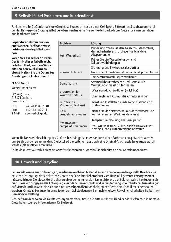
Funktioniert Ihr Gerät nicht wie gewünscht, so liegt es oft nur an einer Kleinigkeit. Bitte prüfen Sie, ob aufgrund fol-gender Hinweise die Störung selbst behoben werden kann. Sie vermeiden dadurch die Kosten für einen unnötigen Kundendiensteinsatz.
Problem Lösung
Kein Wasserfluss
Prüfen und öffnen Sie den Wasserhauptanschluss, das Sicherheitsventil und eventuelle andere Absperrventile
Prüfen Sie die Wasserleitungen und Schlauchverbindungen
Wasser bleibt kalt
Sicherung und Elektroanschluss prüfen
Heizelement durch Werkskundendienst prüfen lassen
Temperatureinstellung kontrollieren
Dampfaustritt Stromzufuhr unterbrechen und Gerät durch Werkskundendienst prüfen lassen
Unzureichender Warmwasserfluss
Wasserdruck kontrollieren (< 1,5 bar)
Strahlregler am Auslauf der Armatur reinigen
Kurzschluss (Sicherung löst aus)
Gerät und Installation durch Werkskundendienst prüfen lassen
Kein Ausdehnungswasser
ziehen Sie den Netzstecker aus der Steckdose und kontaktieren den Werkskundendienst
Warmwasser-temperatur zu niedrig
Temperatureinstellung am Gerät prüfen
evtl. wurde in kurzer Zeit zu viel Warmwasser ent-nommen, dann Aufheizvorgang abwarten
CLAGE GmbH
Werkskundendienst
Pirolweg 1 – 5 21337 Lüneburg Deutschland
Fon: +49 4131 8901-40 Fax: +49 4131 8901-41 E-Mail: [email protected]
Wenn die Netzanschlussleitung des Gerätes beschädigt ist, muss sie durch einen Fachmann ausgetauscht werden, um Gefährdungen zu vermeiden. Die beschädigte Leitung muss durch eine Original-Anschlussleitung ausgetauscht werden (als Ersatzteil erhältlich).
Sollte das Gerät weiterhin nicht einwandfrei funktionieren, wenden Sie sich bitte an den Werkskundendienst.
Reparaturen dürfen nur von aner kann ten Fach hand werks-betrieben durchgeführt wer-den.
Wenn sich ein Fehler an Ihrem Gerät mit dieser Tabelle nicht beheben lässt, wenden Sie sich bitte an den Werks kunden-dienst. Halten Sie die Daten des Geräte typen schildes bereit!
10. Umwelt und Recycling
Ihr Produkt wurde aus hochwertigen, wiederverwendbaren Materialien und Kompo nenten hergestellt. Beachten Sie bei einer Entsorgung, dass elektrische Geräte am Ende ihrer Lebensdauer vom Hausmüll getrennt entsorgt werden müssen. Bringen Sie dieses Gerät daher zu einer der kommunalen Sammelstellen, die Elektronikschrott entgegenneh-men. Diese ordnungsgemäße Entsorgung dient dem Umweltschutz und verhindert mögliche schädliche Auswirkungen auf Mensch und Umwelt, die sich aus einer unsachgemäßen Handhabung der Geräte am Ende ihrer Lebensdauer ergeben könnten. Genauere Infor ma tionen zur nächstgelegenen Sammelstelle bzw. Recyclinghof erhalten Sie bei Ihrer Gemeinde verwaltung.
Geschäftskunden: Wenn Sie Geräte entsorgen möchten, treten Sie bitte mit Ihrem Händler oder Lieferanten in Kontakt. Diese halten weitere Informationen für Sie bereit.
CLAGE
11
Contents
1. Safety instructions . . . . . . . . . . . . . . . . . . . . . . . . . . . . . . . . . . . . . . . . . . . . . . . . . . . . . . . . . . . . 12
2. Legionella prevention . . . . . . . . . . . . . . . . . . . . . . . . . . . . . . . . . . . . . . . . . . . . . . . . . . . . . . . . . 14
Recommendations based on European standard CEN/TR 16355 . . . . . . . . . . . . . . . . . . . . . . 14
General recommendations . . . . . . . . . . . . . . . . . . . . . . . . . . . . . . . . . . . . . . . . . . . . . . . . . . . . . 14
Types of hot water installation . . . . . . . . . . . . . . . . . . . . . . . . . . . . . . . . . . . . . . . . . . . . . . . . . . 14
3. Overview . . . . . . . . . . . . . . . . . . . . . . . . . . . . . . . . . . . . . . . . . . . . . . . . . . . . . . . . . . . . . . . . . . . . 15
4. Technical Data . . . . . . . . . . . . . . . . . . . . . . . . . . . . . . . . . . . . . . . . . . . . . . . . . . . . . . . . . . . . . . . 15
5. Installation . . . . . . . . . . . . . . . . . . . . . . . . . . . . . . . . . . . . . . . . . . . . . . . . . . . . . . . . . . . . . . . . . . 16
Installing the appliance . . . . . . . . . . . . . . . . . . . . . . . . . . . . . . . . . . . . . . . . . . . . . . . . . . . . . . . . 16
Water connection . . . . . . . . . . . . . . . . . . . . . . . . . . . . . . . . . . . . . . . . . . . . . . . . . . . . . . . . . . . . . 16
Closed operation. . . . . . . . . . . . . . . . . . . . . . . . . . . . . . . . . . . . . . . . . . . . . . . . . . . . . . . . . . . . . . 17
Open operation. . . . . . . . . . . . . . . . . . . . . . . . . . . . . . . . . . . . . . . . . . . . . . . . . . . . . . . . . . . . . . . 17
Electrical connection. . . . . . . . . . . . . . . . . . . . . . . . . . . . . . . . . . . . . . . . . . . . . . . . . . . . . . . . . . . 17
6. Initial operation . . . . . . . . . . . . . . . . . . . . . . . . . . . . . . . . . . . . . . . . . . . . . . . . . . . . . . . . . . . . . . 17
Initial Use . . . . . . . . . . . . . . . . . . . . . . . . . . . . . . . . . . . . . . . . . . . . . . . . . . . . . . . . . . . . . . . . . . . 17
7. How to use . . . . . . . . . . . . . . . . . . . . . . . . . . . . . . . . . . . . . . . . . . . . . . . . . . . . . . . . . . . . . . . . . . 18
Adjusting the temperature . . . . . . . . . . . . . . . . . . . . . . . . . . . . . . . . . . . . . . . . . . . . . . . . . . . . . 18
8. Maintenance and cleaning . . . . . . . . . . . . . . . . . . . . . . . . . . . . . . . . . . . . . . . . . . . . . . . . . . . . . 18
Maintenance regulations. . . . . . . . . . . . . . . . . . . . . . . . . . . . . . . . . . . . . . . . . . . . . . . . . . . . . . . 18
9. Trouble-shooting and service . . . . . . . . . . . . . . . . . . . . . . . . . . . . . . . . . . . . . . . . . . . . . . . . . . . 19
10. Environment and recycling . . . . . . . . . . . . . . . . . . . . . . . . . . . . . . . . . . . . . . . . . . . . . . . . . . . . 19
11. Product data sheet in accordance with EU regulation - 812/2013 814/2013. . . . . . . . . . 20
12. Figures. . . . . . . . . . . . . . . . . . . . . . . . . . . . . . . . . . . . . . . . . . . . . . . . . . . . . . . . . . . . . . . . . . . . . . . I
S 50 / S 80 / S 100
12
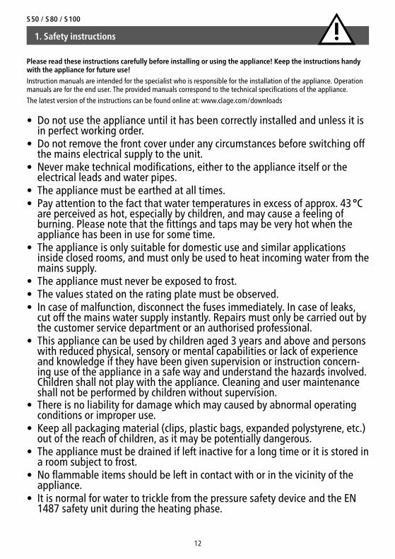
1. Safety instructions
Please read these instructions carefully before installing or using the appliance! Keep the instructions handy with the appliance for future use!
Instruction manuals are intended for the specialist who is responsible for the installation of the appliance. Operation manuals are for the end user. The provided manuals correspond to the technical specifications of the appliance.
The latest version of the instructions can be found online at: www.clage.com/downloads
• Do not use the appliance until it has been correctly installed and unless it is in perfect working order.
• Do not remove the front cover under any circumstances before switching off the mains electrical supply to the unit.
• Never make technical modifications, either to the appliance itself or the electrical leads and water pipes.
• The appliance must be earthed at all times. • Pay attention to the fact that water temperatures in excess of approx. 43 °C
are perceived as hot, especially by children, and may cause a feeling of burning. Please note that the fittings and taps may be very hot when the appliance has been in use for some time.
• The appliance is only suitable for domestic use and similar applications inside closed rooms, and must only be used to heat incoming water from the mains supply.
• The appliance must never be exposed to frost. • The values stated on the rating plate must be observed.• In case of malfunction, disconnect the fuses immediately. In case of leaks,
cut off the mains water supply instantly. Repairs must only be carried out by the customer service department or an authorised professional.
• This appliance can be used by children aged 3 years and above and persons with reduced physical, sensory or mental capabilities or lack of experience and knowledge if they have been given supervision or ins truction concern-ing use of the appliance in a safe way and understand the hazards involved. Children shall not play with the appliance. Cleaning and user maintenance shall not be performed by children without supervision.
• There is no liability for damage which may caused by abnormal operating conditions or improper use.
• Keep all packaging material (clips, plastic bags, expanded polystyrene, etc.) out of the reach of children, as it may be potentially dangerous.
• The appliance must be drained if left inactive for a long time or it is stored in a room subject to frost.
• No flammable items should be left in contact with or in the vicinity of the appliance.
• It is normal for water to trickle from the pressure safety device and the EN 1487 safety unit during the heating phase.
CLAGE
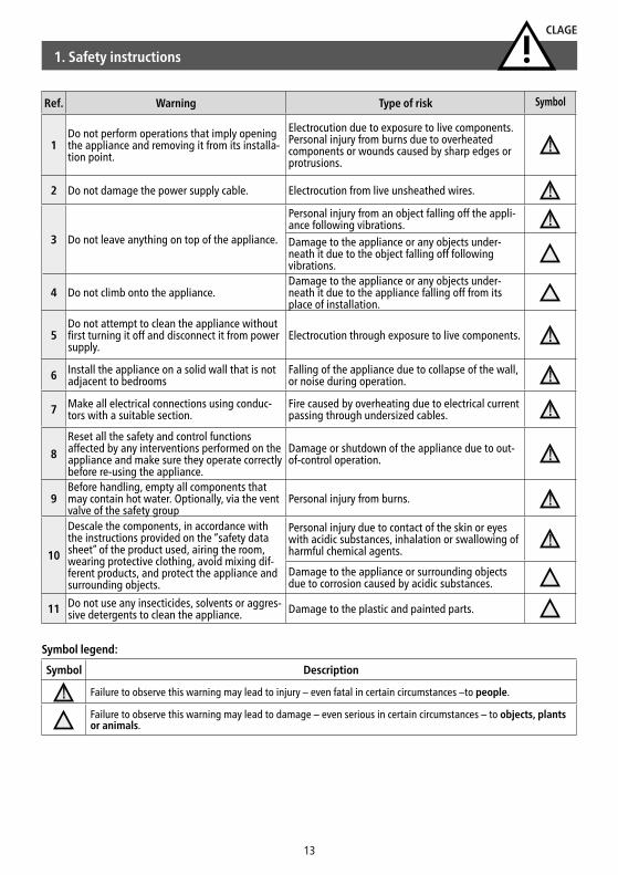
Symbol Description
Failure to observe this warning may lead to injury – even fatal in certain circumstances –to people.
Failure to observe this warning may lead to damage – even serious in certain circumstances – to objects, plants or animals.
Ref. Warning Type of risk Symbol
1Do not perform operations that imply opening the appliance and removing it from its installa-tion point.
Electrocution due to exposure to live components. Personal injury from burns due to overheated components or wounds caused by sharp edges or protrusions.
2 Do not damage the power supply cable. Electrocution from live unsheathed wires.
3 Do not leave anything on top of the appliance.
Personal injury from an object falling off the appli-ance following vibrations.Damage to the appliance or any objects under-neath it due to the object falling off following vibrations.
4 Do not climb onto the appliance.Damage to the appliance or any objects under-neath it due to the appliance falling off from its place of installation.
5Do not attempt to clean the appliance without first turning it off and disconnect it from power supply.
Electrocution through exposure to live components.
6 Install the appliance on a solid wall that is not adjacent to bedrooms
Falling of the appliance due to collapse of the wall, or noise during operation.
7 Make all electrical connections using conduc-tors with a suitable section.
Fire caused by overheating due to electrical current passing through undersized cables.
8
Reset all the safety and control functions affected by any interventions performed on the appliance and make sure they operate correctly before re-using the appliance.
Damage or shutdown of the appliance due to out-of-control operation.
9Before handling, empty all components that may contain hot water. Optionally, via the vent valve of the safety group
Personal injury from burns.
10
Descale the components, in accordance with the instructions provided on the “safety data sheet” of the product used, airing the room, wearing protective clothing, avoid mixing dif-ferent products, and protect the appliance and surrounding objects.
Personal injury due to contact of the skin or eyes with acidic substances, inhalation or swallowing of harmful chemical agents.
Damage to the appliance or surrounding objects due to corrosion caused by acidic substances.
11 Do not use any insecticides, solvents or aggres-sive detergents to clean the appliance. Damage to the plastic and painted parts.
13
Symbol legend:
1. Safety instructions
S 50 / S 80 / S 100
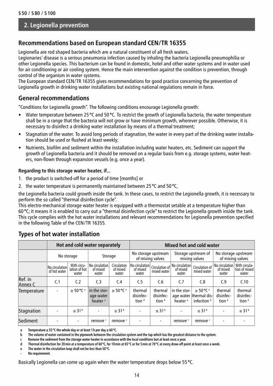
Hot and cold water separately Mixed hot and cold water
No storage Storage No storage upstream of mixing valves
Storage upstream of mixing valves
No storage upstream of mixing valves
No circulation of hot water
With circu-lation of hot
water
No circulation of mixed
water
Circulationof mixed
water
No circulation of mixed
waterCirculation of mixed water
No circulation of mixed
waterCirculation of mixed water
No circulation of mixed
water
With circula-tion of mixed
waterRef. inAnnex C C.1 C.2 C.3 C.4 C.5 C.6 C.7 C.8 C.9 C.10
Temperature - ≥ 50 °C e in the stor-age water
heater a
≥ 50 °C e thermal disinfec-
tion d
thermal disinfec-
tion d
in the stor-age water
heater a
≥ 50 °C e thermal dis-infection d
thermal disinfec-
tion d
thermal disinfec-
tion d
Stagnation - ≤ 3 l b - ≤ 3 l b - ≤ 3 l b - ≤ 3 l b - ≤ 3 l b
Sediment - - remove c remove c - - remove c remove c - -
a Temperature ≥ 55 °C the whole day or at least 1 h per day ≥ 60 °C.b The volume of water contained in the pipework between the circulation system and the tap which has the greatest distance to the system.c Remove the sediment from the storage water heater in accordance with the local conditions but at least once a year.d Thermal disinfection for 20 min at a temperature of 60 °C, for 10 min at 65 °C or for 5 min at 70 °C at every draw-off point at least once a week.e The water in the circulation loop shall not be less than 50 °C.- No requirement.
14
Recommendations based on European standard CEN/TR 16355Legionella are rod shaped bacteria which are a natural constituent of all fresh waters. Legionaries’ disease is a serious pneumonia infection caused by inhaling the bacteria Legionella pneumophilia or other Legionella species. This bacterium can be found in domestic, hotel and other water systems and in water used for air conditioning or air cooling system. Hence the main intervention against the condition is prevention, through control of the organism in water systems. The European standard CEN/TR 16355 gives recommendations for good practice concerning the prevention of Legionella growth in drinking water installations but existing national regulations remain in force.
General recommendations “Conditions for Legionella growth”. The following conditions encourage Legionella growth:
• Water temperature between 25 °C and 50 °C. To restrict the growth of Legionella bacteria, the water temperature shall be in a range that the bacteria will not grow or have minimum growth, wherever possible. Otherwise, it is necessary to disinfect a drinking water installation by means of a thermal treatment;
• Stagnation of the water. To avoid long periods of stagnation, the water in every part of the drinking water installa-tion should be used or flushed at least weekly;
• Nutrients, biofilm and sediment within the installation including water heaters, etc. Sediment can support the growth of Legionella bacteria and it should be removed on a regular basis from e.g. storage systems, water heat-ers, non-flown through expansion vessels (e.g. once a year).
Regarding to this storage water heater, if...
1. the product is switched-off for a period of time [months] or
2. the water temperature is permanently maintained between 25 °C and 50 °C,
the Legionella bacteria could growth inside the tank. In these cases, to restrict the Legionella growth, it is necessary to perform the so called “thermal disinfection cycle”. This electro-mechanical storage water heater is equipped with a thermostat setable at a temperature higher than 60 °C; it means it is enabled to carry out a “thermal disinfection cycle” to restrict the Legionella growth inside the tank. This cycle complies with the hot water installations and relevant recommendations for Legionella prevention specified in the following Table of the CEN/TR 16355.
Types of hot water installation
2. Legionella prevention
Basically Legionella can come up again when the water temperature drops below 55 °C.
CLAGE
Typ : S XX EUNr.: XXXXXX-XXXXXXNenninhalt: XX l
IP25DCLAGE GmbHPirolweg 1-521337 Lüneburg(Deutschland)
Nenndruck: 0.6 MPa (6 bar)
AC 220-240V 50-60 Hz 2000 W 8.7 A
Made in Italy
Behälter: St em
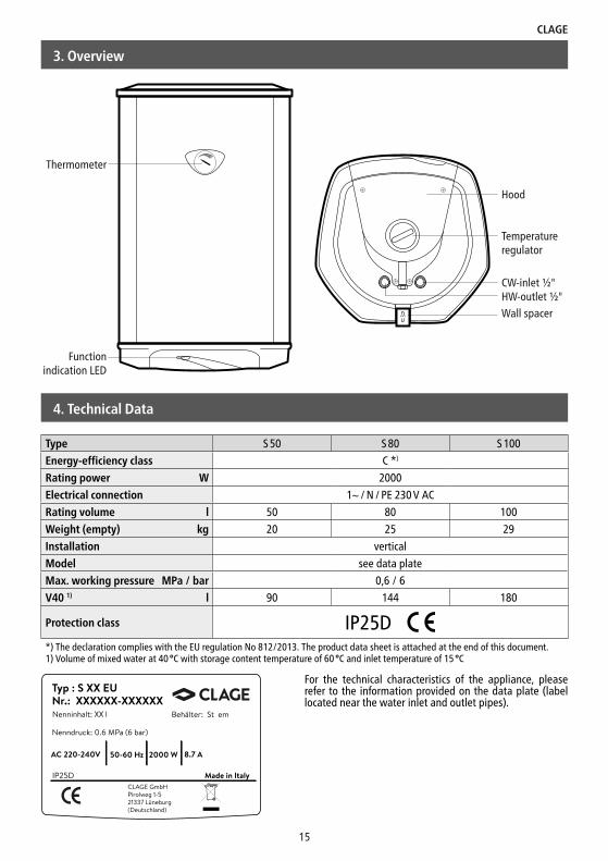
Type S 50 S 80 S 100
Energy-efficiency class C *)
Rating power W 2000
Electrical connection 1~ / N / PE 230 V AC
Rating volume l 50 80 100
Weight (empty) kg 20 25 29
Installation vertical
Model see data plate
Max. working pressure MPa / bar 0,6 / 6
V40 1) l 90 144 180
Protection class IP25D*) The declaration complies with the EU regulation No 812/2013. The product data sheet is attached at the end of this document.1) Volume of mixed water at 40 °C with storage content temperature of 60 °C and inlet temperature of 15 °C
15
4. Technical Data
For the technical characteristics of the appliance, please refer to the information provided on the data plate (label located near the water inlet and outlet pipes).
3. Overview
Thermometer
Function indication LED
Wall spacerHW-outlet ½"CW-inlet ½"
Temperature regulator
Hood
S 50 / S 80 / S 100
5. Installation
16
The following regulations must be observed:
• VDE 0100
• EN 806
• Installation must comply with all statutory regulations, as well as those of the local electricity and water supply companies.
• The rating plate and technical specifications
• Only intact and appropriate tools must be used
• The appliance must be connected to water supply first and be filled with water before connecting it to the power supply.
• The appliance must be installed and commissioned by a qualified technician in accordance with estab-lished regulations and local health and safety regulations
• The appliance must not be exposed to direct sunrays, even in the presence of windows
• Do not use or connect the appliance to a circulation line
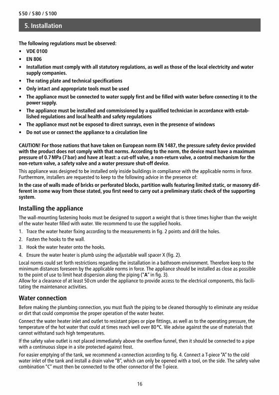
CAUTION! For those nations that have taken on European norm EN 1487, the pressure safety device provided with the product does not comply with that norms. According to the norm, the device must have a maximum pressure of 0.7 MPa (7 bar) and have at least: a cut-off valve, a non-return valve, a control mechanism for the non-return valve, a safety valve and a water pressure shut-off device.
This appliance was designed to be installed only inside buildings in compliance with the applicable norms in force. Furthermore, installers are requested to keep to the following advice in the presence of:
In the case of walls made of bricks or perforated blocks, partition walls featuring limited static, or masonry dif-ferent in some way from those stated, you first need to carry out a preliminary static check of the supporting system.
Installing the applianceThe wall-mounting fastening hooks must be designed to support a weight that is three times higher than the weight of the water heater filled with water. We recommend to use the supplied hooks.
1. Trace the water heater fixing according to the measurements in fig. 2 points and drill the holes.
2. Fasten the hooks to the wall.
3. Hook the water heater onto the hooks.
4. Ensure the water heater is plumb using the adjustable wall spacer X (fig. 2).
Local norms could set forth restrictions regarding the installation in a bathroom environment. Therefore keep to the minimum distances foreseen by the applicable norms in force. The appliance should be installed as close as possible to the point of use to limit heat dispersion along the piping (“A” in fig. 3). Allow for a clearance of at least 50 cm under the appliance to provide access to the electrical components, this facili-tating the maintenance activities.
Water connectionBefore making the plumbing connection, you must flush the piping to be cleaned thoroughly to eliminate any residue or dirt that could compromise the proper operation of the water heater.
Connect the water heater inlet and outlet to resistant pipes or pipe fittings, as well as to the operating pressure, the temperature of the hot water that could at times reach well over 80 °C. We advise against the use of materials that cannot withstand such high temperatures.
If the safety valve outlet is not placed immediately above the overflow funnel, then it should be connected to a pipe with a continuous slope in a site protected against frost.
For easier emptying of the tank, we recommend a connection according to fig. 4. Connect a T-piece “A” to the cold water inlet of the tank and install a drain valve “B”, which can only be opened with a tool, on the side. The safety valve combination “C” must then be connected to the other connector of the T-piece.
CLAGE
17
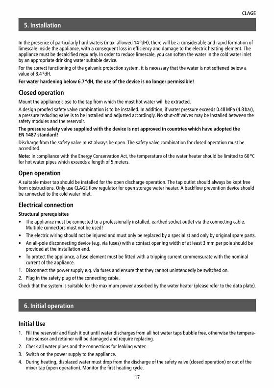
In the presence of particularly hard waters (max. allowed 14 °dH), there will be a considerable and rapid formation of limescale inside the appliance, with a consequent loss in efficiency and damage to the electric heating element. The appliance must be decalcified regularly. In order to reduce limescale, you can soften the water in the cold water inlet by an appropriate drinking water suitable device.
For the correct functioning of the galvanic protection system, it is necessary that the water is not softened below a value of 8.4 °dH.
For water hardening below 6.7 °dH, the use of the device is no longer permissible!
Closed operationMount the appliance close to the tap from which the most hot water will be extracted.
A design proofed safety valve combination is to be installed. In addition, if water pressure exceeds 0.48 MPa (4.8 bar), a pressure reducing valve is to be installed and adjusted accordingly. No shut-off valves may be installed between the safety modules and the reservoir.
The pressure safety valve supplied with the device is not approved in countries which have adopted the EN 1487 standard!
Discharge from the safety valve must always be open. The safety valve combination for closed operation must be accredited.
Note: In compliance with the Energy Conservation Act, the temperature of the water heater should be limited to 60 °C for hot water pipes which exceeds a length of 5 meters.
Open operationA suitable mixer tap should be installed for the open discharge operation. The tap outlet should always be kept free from obstructions. Only use CLAGE flow regulator for open storage water heater. A backflow prevention device should be connected to the cold water inlet.
Electrical connectionStructural prerequisites
• The appliance must be connected to a professionally installed, earthed socket outlet via the connecting cable. Multiple connectors must not be used!
• The electric wiring should not be injured and must only be replaced by a specialist and only by original spare parts.
• An all-pole disconnecting device (e.g. via fuses) with a contact opening width of at least 3 mm per pole should be provided at the installation end.
• To protect the appliance, a fuse element must be fitted with a tripping current commensurate with the nominal current of the appliance.
1. Disconnect the power supply e.g. via fuses and ensure that they cannot unintendedly be switched on.
2. Plug in the safety plug of the connecting cable.
Check that the system is suitable for the maximum power absorbed by the water heater (please refer to the data plate).
5. Installation
Initial Use1. Fill the reservoir and flush it out until water discharges from all hot water taps bubble free, otherwise the tempera-
ture sensor and retainer will be damaged and require replacing.
2. Check all water pipes and the connections for leaking water.
3. Switch on the power supply to the appliance.
4. During heating, displaced water must drop from the discharge of the safety valve (closed operation) or out of the mixer tap (open operation). Monitor the first heating cycle.
6. Initial operation
S 50 / S 80 / S 100
18
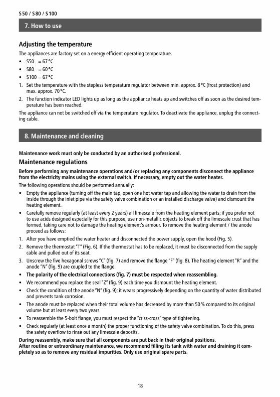
Adjusting the temperatureThe appliances are factory set on a energy efficient operating temperature.
• S50 = 67 °C
• S80 = 60 °C
• S100 = 67 °C
1. Set the temperature with the stepless temperature regulator between min. approx. 8 °C (frost protection) and max. approx. 70 °C.
2. The function indicator LED lights up as long as the appliance heats up and switches off as soon as the desired tem-perature has been reached.
The appliance can not be switched off via the temperature regulator. To deactivate the appliance, unplug the connect-ing cable.
Maintenance regulationsBefore performing any maintenance operations and/or replacing any components disconnect the appliance from the electricity mains using the external switch. If necessary, empty out the water heater.
The following operations should be performed annually:
• Empty the appliance (turning off the main tap, open one hot water tap and allowing the water to drain from the inside through the inlet pipe via the safety valve combination or an installed discharge valve) and dismount the heating element.
• Carefully remove regularly (at least every 2 years) all limescale from the heating element parts; if you prefer not to use acids designed especially for this purpose, use non-metallic objects to break off the limescale crust that has formed, taking care not to damage the heating element’s armour. To remove the heating element / the anode proceed as follows:
1. After you have emptied the water heater and disconnected the power supply, open the hood (Fig. 5).
2. Remove the thermostat “T” (Fig. 6). If the thermostat has to be replaced, it must be disconnected from the supply cable and pulled out of its seat.
3. Unscrew the five hexagonal screws “C” (fig. 7) and remove the flange “F” (fig. 8). The heating element “R” and the anode “N” (fig. 9) are coupled to the flange.
• The polarity of the electrical connections (fig. 7) must be respected when reassembling.
• We recommend you replace the seal “Z” (fig. 9) each time you dismount the heating element.
• Check the condition of the anode “N” (fig. 9); it wears progressively depending on the quantity of water distributed and prevents tank corrosion.
• The anode must be replaced when their total volume has decreased by more than 50 % compared to its original volume but at least every two years.
• To reassemble the 5-bolt flange, you must respect the “criss-cross” type of tightening.
• Check regularly (at least once a month) the proper functioning of the safety valve combination. To do this, press the safety overflow to rinse out any limescale deposits.
During reassembly, make sure that all components are put back in their original positions. After routine or extraordinary maintenance, we recommend filling its tank with water and draining it com-pletely so as to remove any residual impurities. Only use original spare parts.
Maintenance work must only be conducted by an authorised professional.
7. How to use
8. Maintenance and cleaning
CLAGE
19
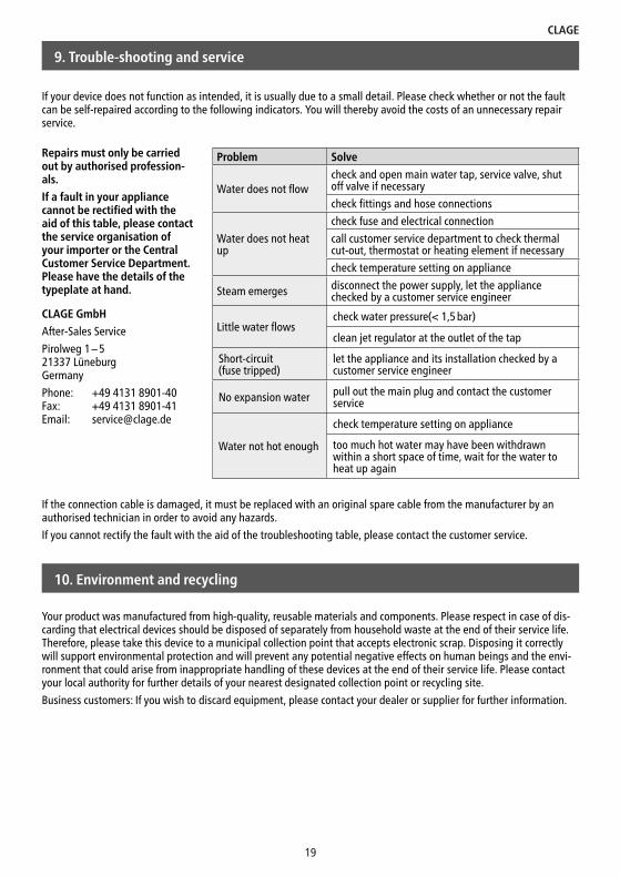
If your device does not function as intended, it is usually due to a small detail. Please check whether or not the fault can be self-repaired according to the following indicators. You will thereby avoid the costs of an unnecessary repair service.
10. Environment and recycling
Your product was manufactured from high-quality, reusable materials and components. Please respect in case of dis-carding that electrical devices should be disposed of separately from household waste at the end of their service life. Therefore, please take this device to a municipal collection point that accepts electronic scrap. Disposing it correctly will support environmental protection and will prevent any potential negative effects on human beings and the envi-ronment that could arise from inappropriate handling of these devices at the end of their service life. Please contact your local authority for further details of your nearest designated collection point or recycling site.
Business customers: If you wish to discard equipment, please contact your dealer or supplier for further information.
CLAGE GmbH
After-Sales Service
Pirolweg 1 – 5 21337 Lüneburg Germany
Phone: +49 4131 8901-40 Fax: +49 4131 8901-41 Email: [email protected]
9. Trouble-shooting and service
Repairs must only be carried out by authorised profession-als.
If a fault in your appliance cannot be rectified with the aid of this table, please contact the service organisation of your importer or the Central Customer Service Department. Please have the details of the typeplate at hand.
If the connection cable is damaged, it must be replaced with an original spare cable from the manufacturer by an authorised technician in order to avoid any hazards.
If you cannot rectify the fault with the aid of the troubleshooting table, please contact the custo mer service.
Problem Solve
Water does not flowcheck and open main water tap, service valve, shut off valve if necessary
check fittings and hose connections
Water does not heat up
check fuse and electrical connection
call customer service department to check thermal cut-out, thermostat or heating element if necessary
check temperature setting on appliance
Steam emerges disconnect the power supply, let the appliance checked by a customer service engineer
Little water flowscheck water pressure(< 1,5 bar)
clean jet regulator at the outlet of the tap
Short-circuit(fuse tripped)
let the appliance and its installation checked by acustomer service engineer
No expansion water pull out the main plug and contact the customer service
Water not hot enough
check temperature setting on appliance
too much hot water may have been withdrawn within a short space of time, wait for the water to heat up again
S 50 / S 80 / S 100
20
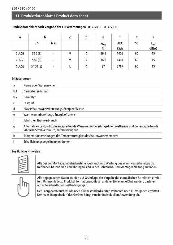
Produktdatenblatt nach Vorgabe der EU Verordnungen - 812/2013 814/2013
a b c d e f h i
b.1 b.2 ηWH AEC °C LWA
% kWh dB(A)
CLAGE S 50 (E) - M C 36,5 1409 60 15
CLAGE S 80 (E) - M C 36,6 1404 60 15
CLAGE S 100 (E) - L C 37 2767 60 15
Erläuterungen
a Name oder Warenzeichen
b.1 Gerätebezeichnung
b.2 Gerätetyp
c Lastprofil
d Klasse Warmwasserbereitungs-Energieeffizienz
e Warmwasserbereitungs-Energieeffizienz
f Jährlicher Stromverbrauch
g Alternatives Lastprofil, die entsprechende Warmwasserbereitungs-Energieeffizienz und der entsprechende jährliche Stromverbrauch, sofern verfügbar.
h Temperatureinstellungen des Temperaturreglers des Warmwasserbereiters
i Schallleistungspegel in Innenräumen
Zusätzliche Hinweise
Alle bei der Montage, Inbetriebnahme, Gebrauch und Wartung des Warmwasserbereiters zu treffenden besonderen Vorkehrungen sind in der Gebrauchs- und Montageanleitung zu finden.
Alle angegebenen Daten wurden auf Grundlage der Vorgabe der europäischen Richtlinien ermit-telt. Unterschiede zu Produktinformationen, die an anderer Stelle angeführt werden, basieren auf unterschiedlichen Testbedingungen.
Der Energieverbrauch wurde nach einem standardisierten Verfahren nach EU-Vorgaben ermittelt. Der reale Energiebedarf des Gerätes hängt von der individuellen Anwendung ab.
11. Produktdatenblatt / Product data sheet
CLAGE
21
11. Produktdatenblatt / Product data sheet
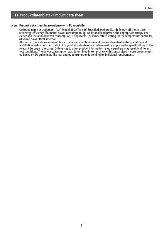
> en Product data sheet in accordance with EU regulation(a) Brand name or trademark, (b.1) Model, (b.2) Type, (c) Specified load profile, (d) Energy-efficiency class, (e) Energy-efficiency, (f) Annual power consumption, (g) Additional load profile, the appropriate energy-effi-ciency and the annual power consumption, if applicable, (h) Temperature setting for the temperature controller, (i) Sound power level, internal.All specific precautions for assembly, installation, maintenance and use are described in the operating and installation instructions. All data in this product data sheet are determined by applying the specifications of the relevant European directives. Differences to other product information listed elsewhere may result in different test conditions. The power consumption was determined in compliance with standardized measurement meth-od based on EU guidelines. The real energy consumption is pending on individual requirements.
I
S 50 / S 80 / S 100
3
X
1
2
320
300
493
100
140
240
134
499
A
G½"
Typ AS 50 613S 80 841
S 100 993
Dimensions in mmAbmessungen in mm
12. Abbildungen / Figures
25
II
CLAGE
4
6
5
8
7
9
12. Abbildungen / Figures
Technische Änderungen, Änderungen der Ausführung und Irrtum vorbehalten. Subject to technical changes, design changes and errors. 9120-91896 05.17
CLAGE GmbHPirolweg 1–5 21337 Lüneburg DeutschlandTelefon: +49 4131 8901-0 Telefax: +49 4131 83200 E-Mail: [email protected] Internet: www.clage.de