geant4 geometry – building your virtual experiment 1 image source: alice experiment
TRANSCRIPT
1
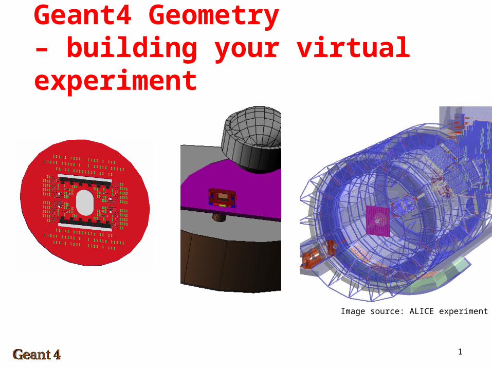
Geant4 Geometry– building your virtual experiment
Image source: ALICE experiment
2
Geant4 Geometry – Building an Experiment
The geometry defines the location and extents of materials in the simulation
At each step in tracking it is checked in which object within the simulation geometry a particle is located.
Simulated geometries can be very simple (e.g. a box) to very complex (e.g. an LHC)
Simulated geometries can be very small (e.g. a SMD-component) to very large (e.g. Earth and its magnetosphere)
Complex geometries lead to longer simulation times and more complex analysis – an important task before implementing a new simulation is defining a geometry which is as detailed as needed but as simple as possible.
3
Detector description
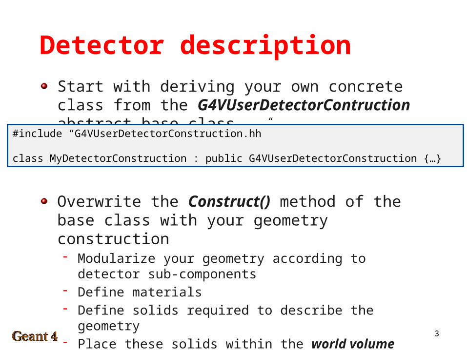
Start with deriving your own concrete class from the G4VUserDetectorContruction abstract base class
Overwrite the Construct() method of the base class with your geometry construction- Modularize your geometry according to detector sub-components- Define materials- Define solids required to describe the geometry- Place these solids within the world volume- Optionally, define sensitive detectors, visualization attributes,
fields and detector regions
#include “G4VUserDetectorConstruction.hh”
class MyDetectorConstruction : public G4VUserDetectorConstruction {…}
4
Example
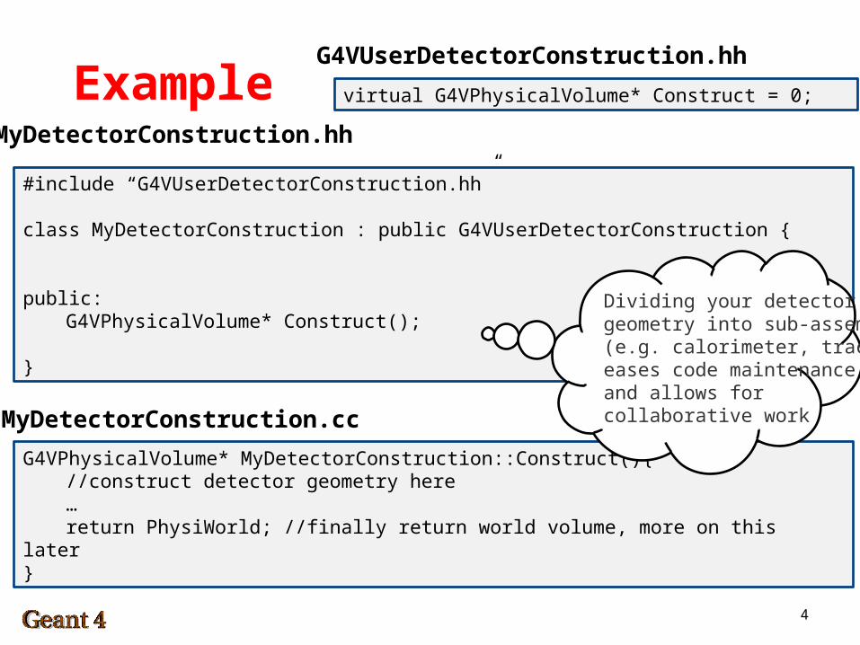
#include “G4VUserDetectorConstruction.hh”
class MyDetectorConstruction : public G4VUserDetectorConstruction {
public:G4VPhysicalVolume* Construct();
}
G4VPhysicalVolume* MyDetectorConstruction::Construct(){//construct detector geometry here…return PhysiWorld; //finally return world volume, more on this
later}
virtual G4VPhysicalVolume* Construct = 0;
MyDetectorConstruction.hh
MyDetectorConstruction.cc
G4VUserDetectorConstruction.hh
Dividing your detectorgeometry into sub-assemblies(e.g. calorimeter, tracker)eases code maintenanceand allows for collaborative work
5
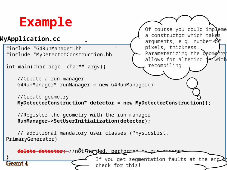
Example
#include “G4RunManager.hh”#include “MyDetectorConstruction.hh”
int main(char argc, char** argv){
//Create a run managerG4RunManager* runManager = new G4RunManager();
//Create geometryMyDetectorConstruction* detector = new MyDetectorConstruction();
//Register the geometry with the run managerRunManager->SetUserInitialization(detector);
// additional mandatory user classes (PhysicsList, PrimaryGenerator)
delete detector; //not needed, performed by run manager}
MyApplication.cc
Of course you could implementa constructor which takesarguments, e.g. number ofpixels, thickness.Parameterizing the geometryallows for altering it without recompiling
If you get segmentation faults at the end of each simulation,check for this!
6
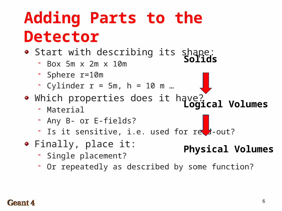
Adding Parts to the Detector
Start with describing its shape:- Box 5m x 2m x 10m- Sphere r=10m- Cylinder r = 5m, h = 10 m …
Which properties does it have?- Material- Any B- or E-fields?- Is it sensitive, i.e. used for read-out?
Finally, place it:- Single placement?- Or repeatedly as described by some function?
Solids
Logical Volumes
Physical Volumes
7
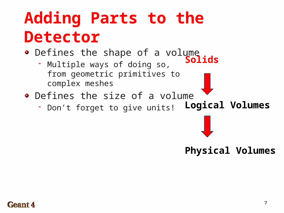
Adding Parts to the Detector
Solids
Logical Volumes
Physical Volumes
Defines the shape of a volume- Multiple ways of doing so,
from geometric primitives tocomplex meshes
Defines the size of a volume- Don’t forget to give units!
8
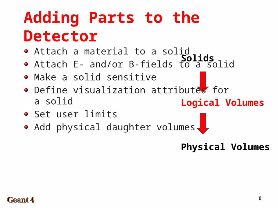
Adding Parts to the Detector
Solids
Logical Volumes
Physical Volumes
Attach a material to a solid
Attach E- and/or B-fields to a solid
Make a solid sensitive
Define visualization attributes fora solid
Set user limits
Add physical daughter volumes
9
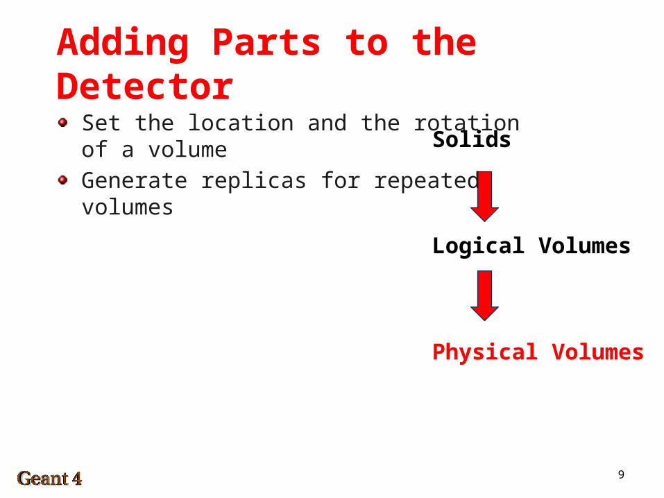
Adding Parts to the Detector
Solids
Logical Volumes
Physical Volumes
Set the location and the rotationof a volume
Generate replicas for repeatedvolumes
10
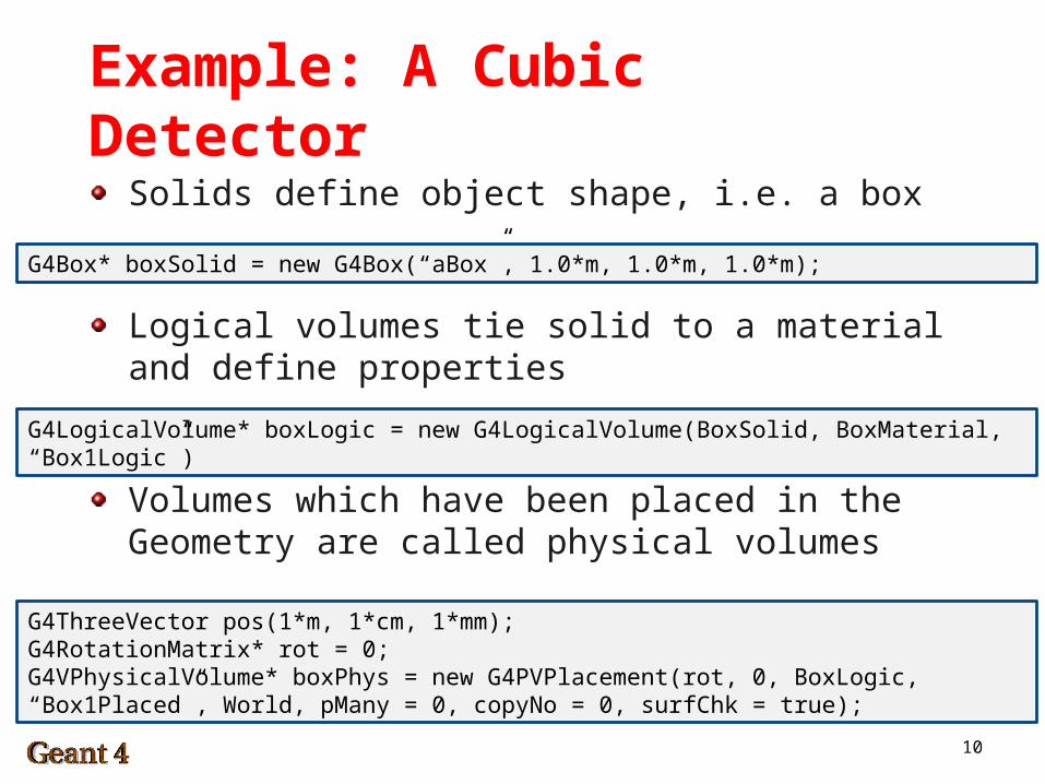
Example: A Cubic Detector
Solids define object shape, i.e. a box
Logical volumes tie solid to a material and define properties
Volumes which have been placed in the Geometry are called physical volumes
G4Box* boxSolid = new G4Box(“aBox”, 1.0*m, 1.0*m, 1.0*m);
G4LogicalVolume* boxLogic = new G4LogicalVolume(BoxSolid, BoxMaterial, “Box1Logic”)
G4ThreeVector pos(1*m, 1*cm, 1*mm);G4RotationMatrix* rot = 0;G4VPhysicalVolume* boxPhys = new G4PVPlacement(rot, 0, BoxLogic, “Box1Placed”, World, pMany = 0, copyNo = 0, surfChk = true);
11
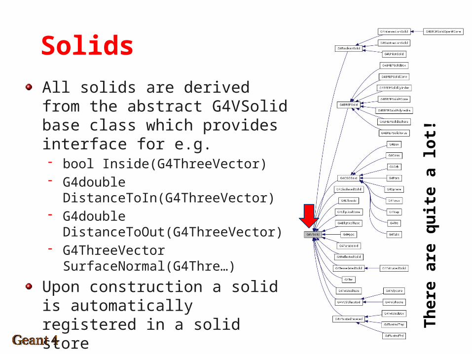
Solids
All solids are derived from the abstract G4VSolid base class which provides interface for e.g.- bool Inside(G4ThreeVector)- G4double DistanceToIn(G4ThreeVector)- G4double DistanceToOut(G4ThreeVector)- G4ThreeVector SurfaceNormal(G4Thre…)
Upon construction a solid is automatically registered in a solid store
Th
ere
are
qu
ite
a lo
t!
12
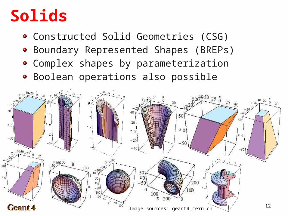
SolidsConstructed Solid Geometries (CSG)
Boundary Represented Shapes (BREPs)
Complex shapes by parameterization
Boolean operations also possible
Image sources: geant4.cern.ch
13
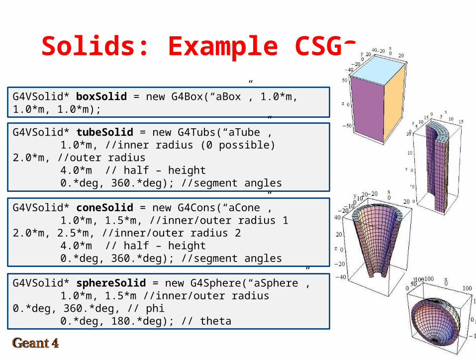
Solids: Example CSGs
G4VSolid* boxSolid = new G4Box(“aBox”, 1.0*m, 1.0*m, 1.0*m);
G4VSolid* tubeSolid = new G4Tubs(“aTube”,1.0*m, //inner radius (0 possible) 2.0*m, //outer radius4.0*m // half – height0.*deg, 360.*deg); //segment
anglesG4VSolid* coneSolid = new G4Cons(“aCone”,
1.0*m, 1.5*m, //inner/outer radius 1 2.0*m, 2.5*m, //inner/outer radius 2
4.0*m // half – height0.*deg, 360.*deg); //segment
anglesG4VSolid* sphereSolid = new G4Sphere(“aSphere”,1.0*m, 1.5*m //inner/outer radius 0.*deg, 360.*deg, // phi0.*deg, 180.*deg); // theta
14
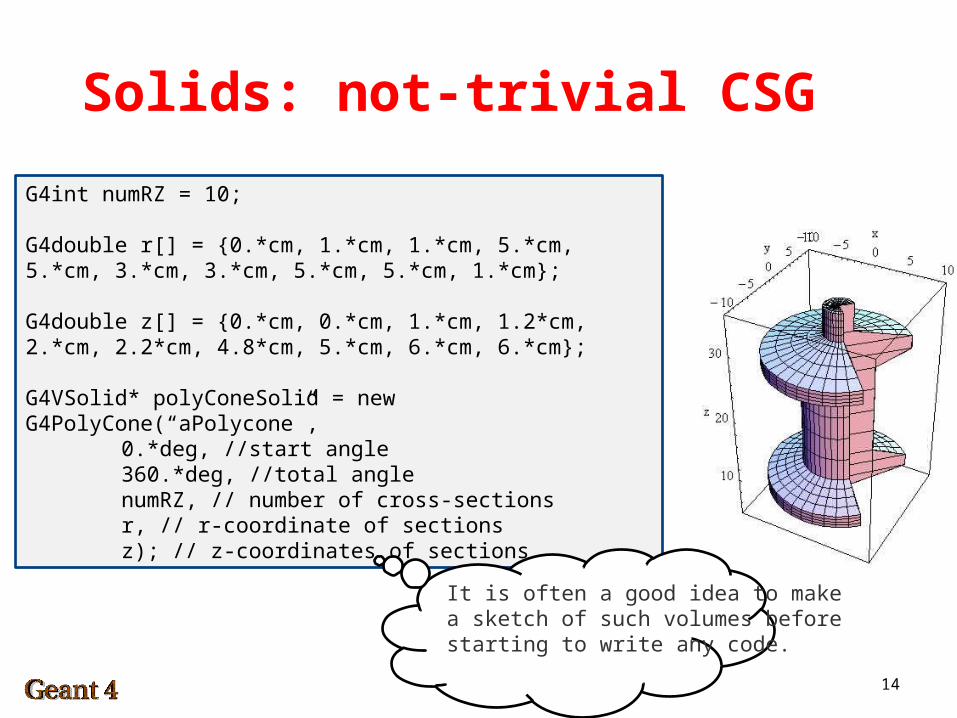
Solids: not-trivial CSG
G4int numRZ = 10;
G4double r[] = {0.*cm, 1.*cm, 1.*cm, 5.*cm, 5.*cm, 3.*cm, 3.*cm, 5.*cm, 5.*cm, 1.*cm};
G4double z[] = {0.*cm, 0.*cm, 1.*cm, 1.2*cm, 2.*cm, 2.2*cm, 4.8*cm, 5.*cm, 6.*cm, 6.*cm};
G4VSolid* polyConeSolid = new G4PolyCone(“aPolycone”,
0.*deg, //start angle360.*deg, //total anglenumRZ, // number of cross-sectionsr, // r-coordinate of sectionsz); // z-coordinates of sections
It is often a good idea to makea sketch of such volumes beforestarting to write any code.
15
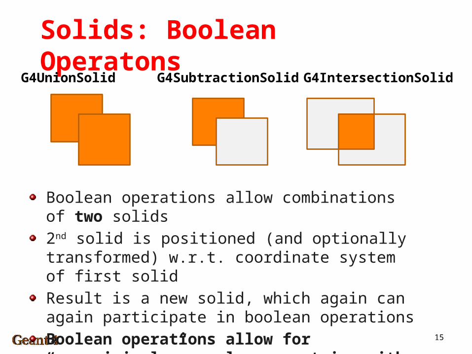
Solids: Boolean OperatonsG4UnionSolid G4SubtractionSolid G4IntersectionSolid
Boolean operations allow combinations of two solids
2nd solid is positioned (and optionally transformed) w.r.t. coordinate system of first solid
Result is a new solid, which again can again participate in boolean operations
Boolean operations allow for “surprisingly” complex geometries with usually quite little effort.
16
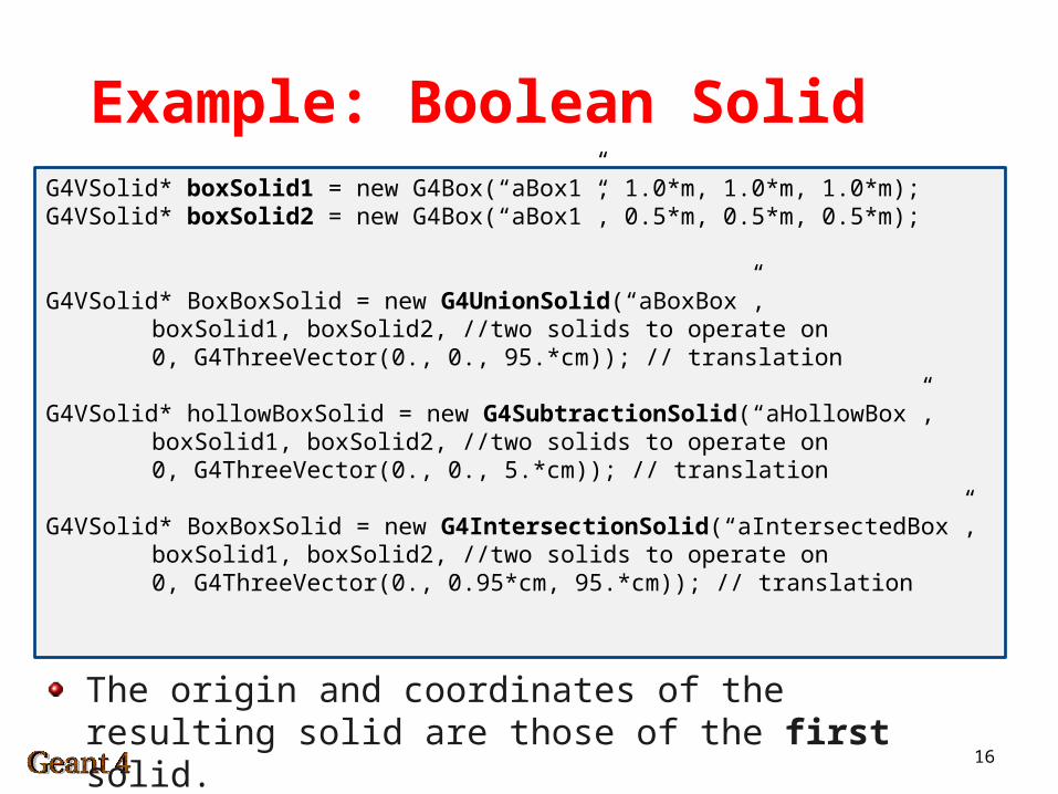
Example: Boolean SolidG4VSolid* boxSolid1 = new G4Box(“aBox1”, 1.0*m, 1.0*m, 1.0*m);G4VSolid* boxSolid2 = new G4Box(“aBox1”, 0.5*m, 0.5*m, 0.5*m);
G4VSolid* BoxBoxSolid = new G4UnionSolid(“aBoxBox”,boxSolid1, boxSolid2, //two solids to operate on0, G4ThreeVector(0., 0., 95.*cm)); // translation
G4VSolid* hollowBoxSolid = new G4SubtractionSolid(“aHollowBox”,boxSolid1, boxSolid2, //two solids to operate on0, G4ThreeVector(0., 0., 5.*cm)); // translation
G4VSolid* BoxBoxSolid = new G4IntersectionSolid(“aIntersectedBox”,boxSolid1, boxSolid2, //two solids to operate on0, G4ThreeVector(0., 0.95*cm, 95.*cm)); //
translation
The origin and coordinates of the resulting solid are those of the first solid.
17
Geant4 Geometry – CAD ImportImport from existing CAD models is not trivial
Geant4 can import GDML files – G4GDMLParser- parser.read(“myCoolGeometry.gdml”)- G4VPhysicalVolume world = parser.GetWorldVolume();
Problem: most CAD tools do not export GDML
Solution: convert to STEP, open e.g. in FastRad or ST-Developer, convert to GDML- Material information can be lost- Conversion errors may occur
Question to ask: is geometry sufficiently complex that I need to import from CAD or can it be quickly reconstructed from Geant4 provided geometric objects? The latter is usually preferable if possible.
18
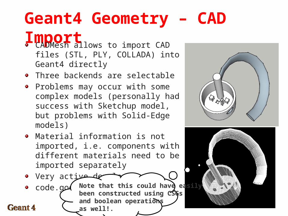
Geant4 Geometry – CAD ImportCADMesh allows to import CAD files (STL, PLY, COLLADA) into Geant4 directly
Three backends are selectable
Problems may occur with some complex models (personally had success with Sketchup model, but problems with Solid-Edge models)
Material information is not imported, i.e. components with different materials need to be imported separately
Very active developers
code.google.com/p/cadmesh
Note that this could have easily been constructed using CSGsand boolean operationsas well!.
19
Logical Volumes
The solids just discussed define the shape and size of a volume
Now let’s add properties to it:- Materials- E-/B- fields- Visualization attributes- Sensitivity- Position of daughter volumes- Regions
A logical volume does not define the position and rotation of a volume (physical volumes define these)
Logical volumes can be shared amongst physical volumes of the same type
20
Logical Volumes
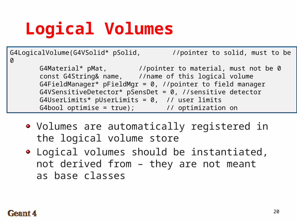
Volumes are automatically registered in the logical volume store
Logical volumes should be instantiated, not derived from – they are not meant as base classes
G4LogicalVolume(G4VSolid* pSolid, //pointer to solid, must to be 0
G4Material* pMat, //pointer to material, must not be 0
const G4String& name, //name of this logical volumeG4FieldManager* pFieldMgr = 0, //pointer to field
managerG4VSensitiveDetector* pSensDet = 0, //sensitive detectorG4UserLimits* pUserLimits = 0, // user limitsG4bool optimise = true); // optimization on
21
Physical Volumes
So far we have created a description of our volume:- Defined shape and size of volume (Solid)- Defined properties such as material, sensitivity (Logical volume)
Now we make it “physical” by actually placing it:- Define position and rotation with respect to other (logical)
volumes
=> Physical volumes are placed instances of logical volumes
22
Physical Volumes
Multiple options exist for placing volumes- Single placement of a volume- Repeated placement as replicas or parameterized volumes (think
of a detector which has many identical subcomponents)- A logical volume max be placed more than once (be careful that
you distinguish it properly e.g. when using it as a sensitive detector)
Volumes in Geant4 constitute a hierarchical geometry- At the top: the root volume, often referred to as the world volume- All other volumes have a mother volume- A mother volume may have any number of daughter volumes
Physical volumes derive from G4VPhysicalVolume
23
Hierarchical Placement
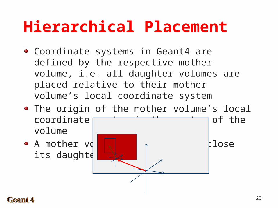
Coordinate systems in Geant4 are defined by the respective mother volume, i.e. all daughter volumes are placed relative to their mother volume’s local coordinate system
The origin of the mother volume’s local coordinate system is the center of the volume
A mother volume has to fully enclose its daughter volumes
24
Hierarchical Placement
A logical mother volume knows about the physical volumes it contains, it is the unique mother volume to these.
If a logical mother volume is placed multiple times, all daughter volumes (and accordingly also daughters of daughters) appear in all physical instances of this mother.
The hierarchy requires a root volume, known as the world volume- Defines the global coordinate system with origin at its center- The position of a particle track is given relative to the world
coordinate system- The simplest world volume is a box
25
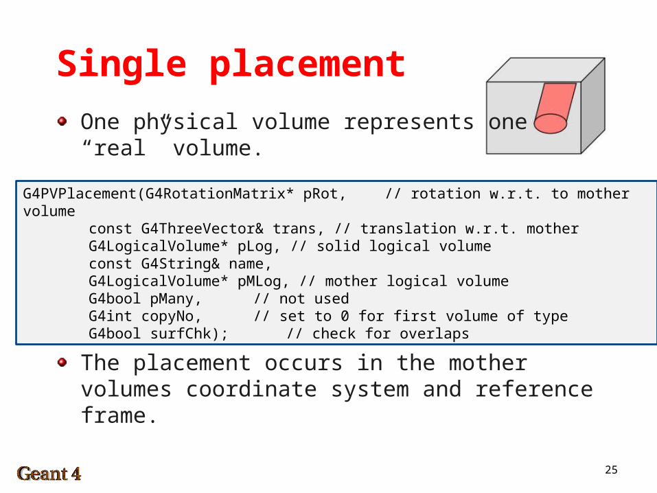
Single placement
One physical volume represents one “real” volume.
The placement occurs in the mother volumes coordinate system and reference frame.
G4PVPlacement(G4RotationMatrix* pRot, // rotation w.r.t. to mother volume
const G4ThreeVector& trans, // translation w.r.t. motherG4LogicalVolume* pLog, // solid logical volumeconst G4String& name,G4LogicalVolume* pMLog, // mother logical volumeG4bool pMany, // not usedG4int copyNo, // set to 0 for first volume of
typeG4bool surfChk); // check for overlaps
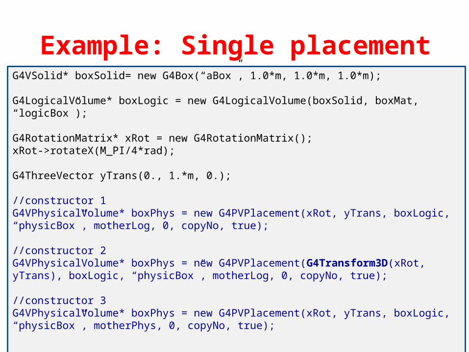
26
Example: Single placementG4VSolid* boxSolid= new G4Box(“aBox”, 1.0*m, 1.0*m, 1.0*m);
G4LogicalVolume* boxLogic = new G4LogicalVolume(boxSolid, boxMat, “logicBox”);
G4RotationMatrix* xRot = new G4RotationMatrix();xRot->rotateX(M_PI/4*rad);
G4ThreeVector yTrans(0., 1.*m, 0.);
//constructor 1G4VPhysicalVolume* boxPhys = new G4PVPlacement(xRot, yTrans, boxLogic, “physicBox”, motherLog, 0, copyNo, true);
//constructor 2G4VPhysicalVolume* boxPhys = new G4PVPlacement(G4Transform3D(xRot, yTrans), boxLogic, “physicBox”, motherLog, 0, copyNo, true);
//constructor 3G4VPhysicalVolume* boxPhys = new G4PVPlacement(xRot, yTrans, boxLogic, “physicBox”, motherPhys, 0, copyNo, true);
27
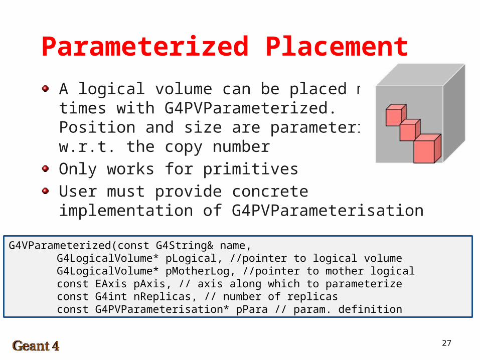
Parameterized Placement
A logical volume can be placed multipletimes with G4PVParameterized.Position and size are parameterizedw.r.t. the copy number
Only works for primitives
User must provide concrete implementation of G4PVParameterisation
G4VParameterized(const G4String& name,G4LogicalVolume* pLogical, //pointer to logical volumeG4LogicalVolume* pMotherLog, //pointer to mother logicalconst EAxis pAxis, // axis along which to parameterizeconst G4int nReplicas, // number of replicasconst G4PVParameterisation* pPara // param. definition
28
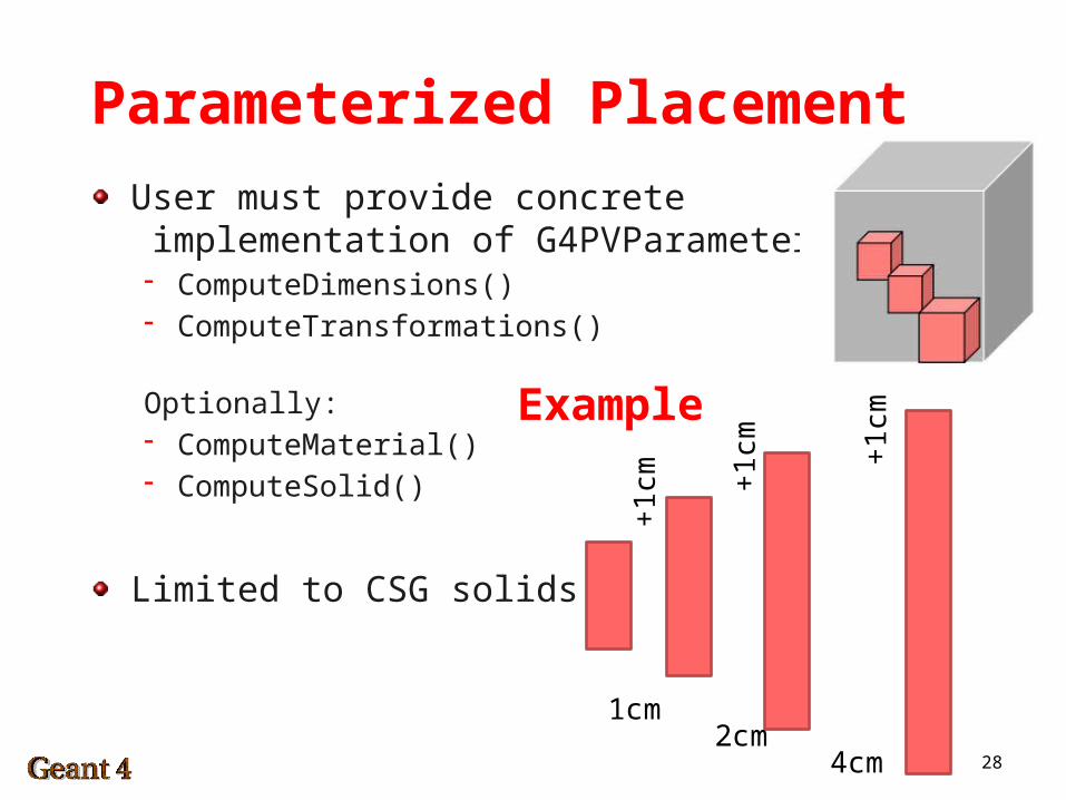
Parameterized Placement
User must provide concrete implementation of G4PVParameterisation- ComputeDimensions()- ComputeTransformations()
Optionally:- ComputeMaterial()- ComputeSolid()
Limited to CSG solids
1cm2cm
4cm
+1
cm +1
cm +1
cmExample
29
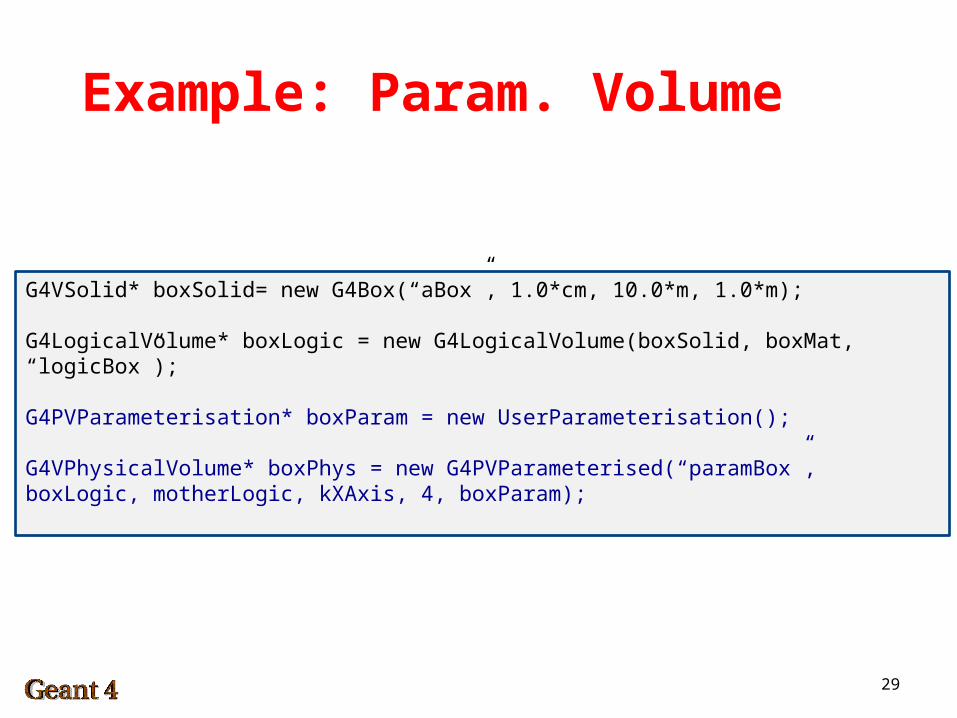
Example: Param. Volume
G4VSolid* boxSolid= new G4Box(“aBox”, 1.0*cm, 10.0*m, 1.0*m);
G4LogicalVolume* boxLogic = new G4LogicalVolume(boxSolid, boxMat, “logicBox”);
G4PVParameterisation* boxParam = new UserParameterisation();
G4VPhysicalVolume* boxPhys = new G4PVParameterised(“paramBox”, boxLogic, motherLogic, kXAxis, 4, boxParam);
30
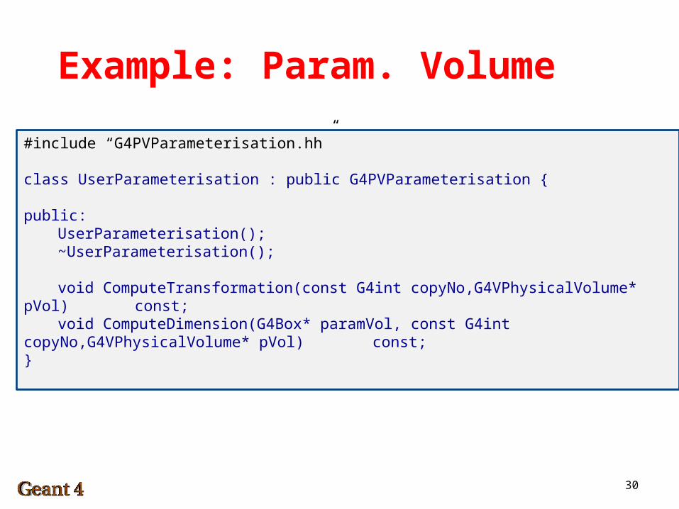
Example: Param. Volume
#include “G4PVParameterisation.hh”
class UserParameterisation : public G4PVParameterisation {
public:UserParameterisation();~UserParameterisation();
void ComputeTransformation(const G4int copyNo,G4VPhysicalVolume* pVol) const;
void ComputeDimension(G4Box* paramVol, const G4int copyNo,G4VPhysicalVolume* pVol) const;
}
31
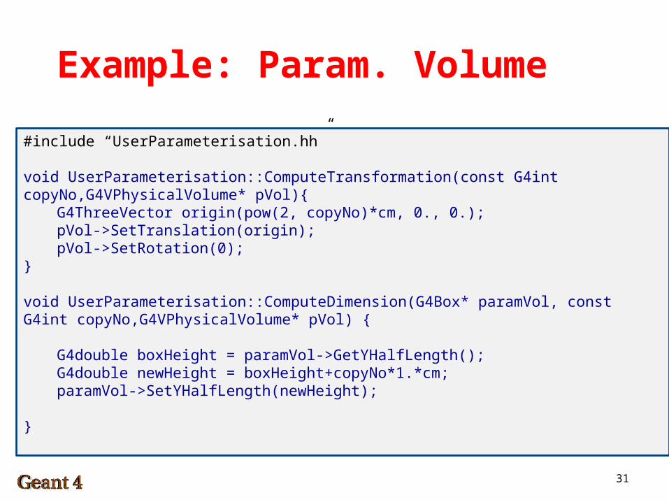
Example: Param. Volume
#include “UserParameterisation.hh”
void UserParameterisation::ComputeTransformation(const G4int copyNo,G4VPhysicalVolume* pVol){
G4ThreeVector origin(pow(2, copyNo)*cm, 0., 0.);pVol->SetTranslation(origin);pVol->SetRotation(0);
}
void UserParameterisation::ComputeDimension(G4Box* paramVol, const G4int copyNo,G4VPhysicalVolume* pVol) {
G4double boxHeight = paramVol->GetYHalfLength();G4double newHeight = boxHeight+copyNo*1.*cm;paramVol->SetYHalfLength(newHeight);
}
32
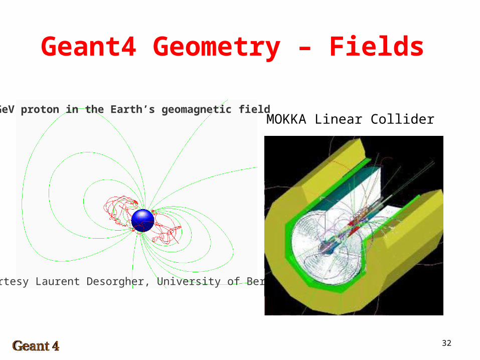
Geant4 Geometry – Fields
Courtesy Laurent Desorgher, University of Bern
1 GeV proton in the Earth’s geomagnetic fieldMOKKA Linear Collider
33
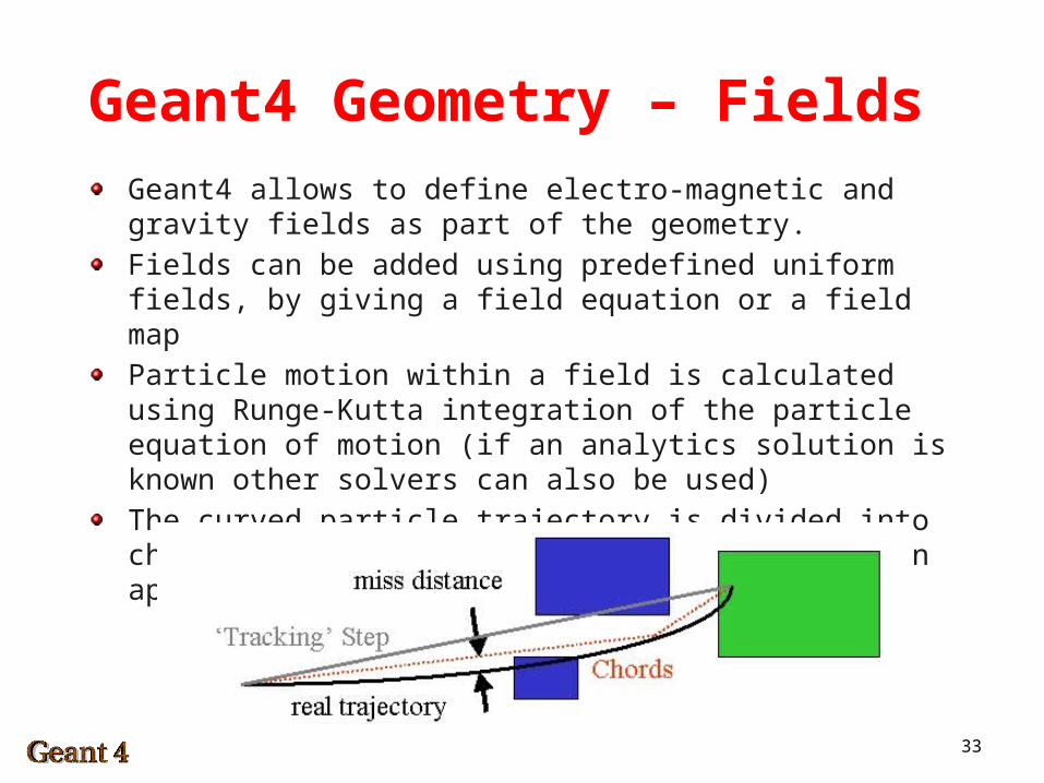
Geant4 Geometry – FieldsGeant4 allows to define electro-magnetic and gravity fields as part of the geometry.
Fields can be added using predefined uniform fields, by giving a field equation or a field map
Particle motion within a field is calculated using Runge-Kutta integration of the particle equation of motion (if an analytics solution is known other solvers can also be used)
The curved particle trajectory is divided into chords, the user is responsible for setting an appropriate precision for this divisions
34
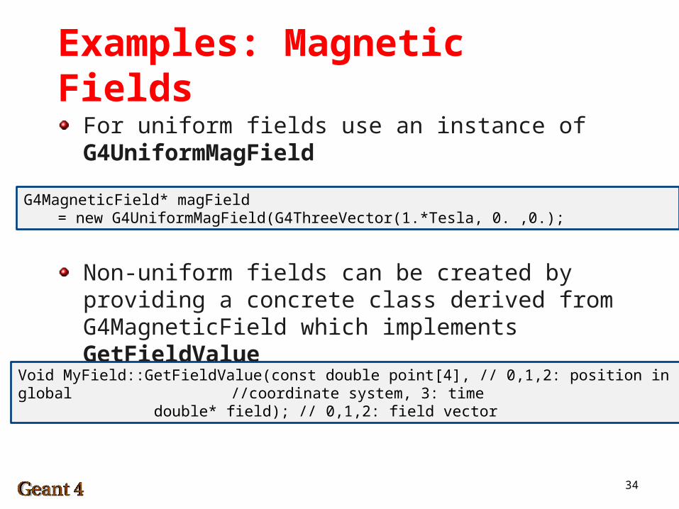
Examples: Magnetic Fields
For uniform fields use an instance of G4UniformMagField
G4MagneticField* magField = new G4UniformMagField(G4ThreeVector(1.*Tesla, 0. ,0.);
Non-uniform fields can be created by providing a concrete class derived from G4MagneticField which implements GetFieldValue
Void MyField::GetFieldValue(const double point[4], // 0,1,2: position in global //coordinate system, 3: time
double* field); // 0,1,2: field vector
35
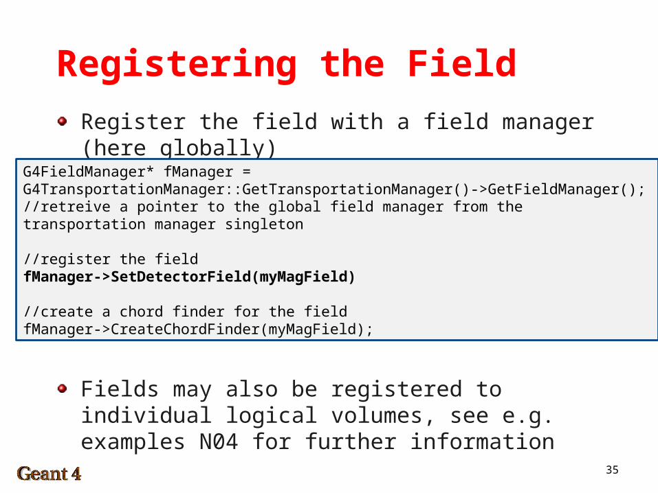
Registering the Field
Register the field with a field manager (here globally)
Fields may also be registered to individual logical volumes, see e.g. examples N04 for further information
G4FieldManager* fManager = G4TransportationManager::GetTransportationManager()->GetFieldManager(); //retreive a pointer to the global field manager from the transportation manager singleton
//register the fieldfManager->SetDetectorField(myMagField)
//create a chord finder for the fieldfManager->CreateChordFinder(myMagField);
36
Regions & Cuts
In Geant4 production thresholds (cuts) are expressed by lengths (i.e. minimum range of secondary) on a per-particle (or global) basis
The user should define appropriate length scales for individual detector components, i.e. 5 micron for a vertex detector but 5 mm for a muon tracker
Simply using small cuts everywhere is not a good choice, it will result in performance penalties!
Cuts can be defined globally or for different detector sub regions.
Thinking about cuts includes thinking about what physics arerelevant … the two go hand in hand
37
Regions & Cuts
The world volume is the default root volume with default cuts as defined in the physics list
Assigning a logical volume to a region makes it a root volume and defines the cuts for all its daughter volumes (hierarchy applies, i.e. a daughter may be assigned to another region)
A region cannot be shared amongst multiple logical volumes
38
Regions & Cuts
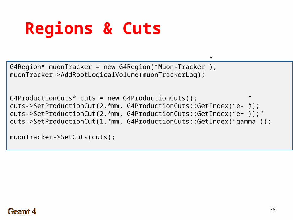
G4Region* muonTracker = new G4Region(“Muon-Tracker”);muonTracker->AddRootLogicalVolume(muonTrackerLog);
G4ProductionCuts* cuts = new G4ProductionCuts();cuts->SetProductionCut(2.*mm, G4ProductionCuts::GetIndex(“e-”));cuts->SetProductionCut(2.*mm, G4ProductionCuts::GetIndex(“e+”));cuts->SetProductionCut(1.*mm, G4ProductionCuts::GetIndex(“gamma”));
muonTracker->SetCuts(cuts);
39
Read Out Geometries
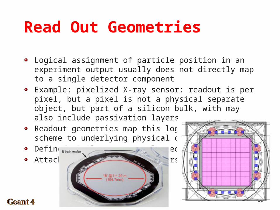
Logical assignment of particle position in an experiment output usually does not directly map to a single detector component
Example: pixelized X-ray sensor: readout is per pixel, but a pixel is not a physical separate object, but part of a silicon bulk, with may also include passivation layers
Readout geometries map this logical output scheme to underlying physical components.
Defined similar to “normal” geometries
Attaches to sensitive detectors
40
Read Out Geometries
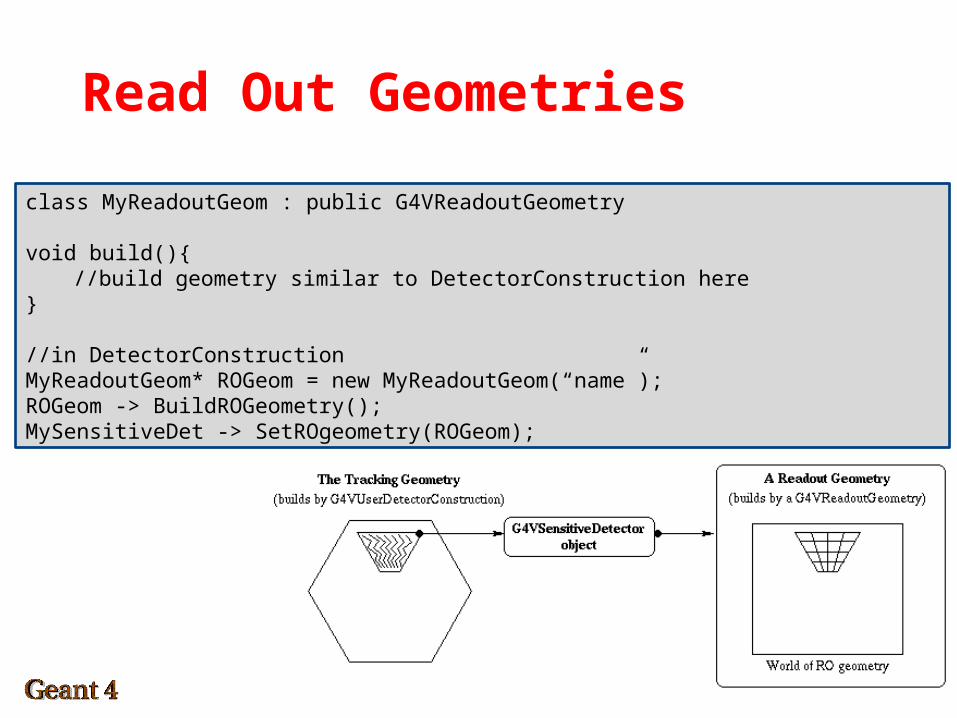
class MyReadoutGeom : public G4VReadoutGeometry
void build(){//build geometry similar to DetectorConstruction here
}
//in DetectorConstructionMyReadoutGeom* ROGeom = new MyReadoutGeom(“name”);ROGeom -> BuildROGeometry();MySensitiveDet -> SetROgeometry(ROGeom);
41
Debugging Geometries
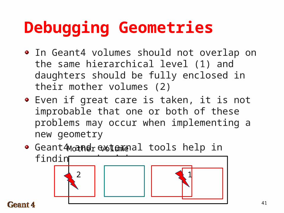
In Geant4 volumes should not overlap on the same hierarchical level (1) and daughters should be fully enclosed in their mother volumes (2)
Even if great care is taken, it is not improbable that one or both of these problems may occur when implementing a new geometry
Geant4 and external tools help in finding such mishaps
Mother volume
12
42
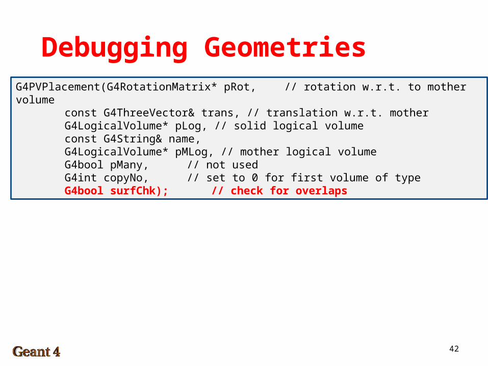
Debugging GeometriesG4PVPlacement(G4RotationMatrix* pRot, // rotation w.r.t. to mother volume
const G4ThreeVector& trans, // translation w.r.t. motherG4LogicalVolume* pLog, // solid logical volumeconst G4String& name,G4LogicalVolume* pMLog, // mother logical volumeG4bool pMany, // not usedG4int copyNo, // set to 0 for first volume of
typeG4bool surfChk); // check for overlaps
43
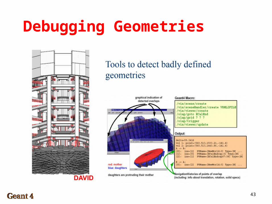
Debugging Geometries
44
Debugging Geometries
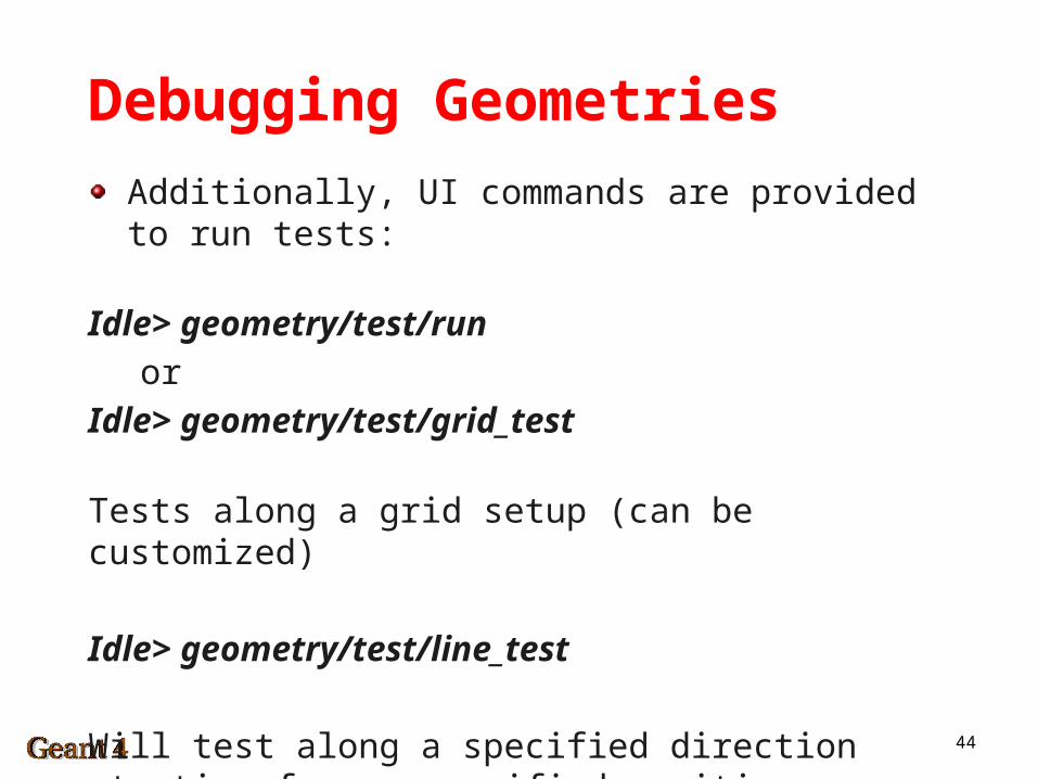
Additionally, UI commands are provided to run tests:
Idle> geometry/test/run
or
Idle> geometry/test/grid_test
Tests along a grid setup (can be customized)
Idle> geometry/test/line_test
Will test along a specified direction starting from a specified position
45
Geometry Hints
Before you start coding:- Think about how to simplify the real world detector. You usually
do not need to model every nut and bolt!- Think about ifyour detector can be grouped into sub-
components/assemblies. Do they require different levels of detail? Do they require different cuts – define regions where appropriate.
- Identify which components are repetitive, and whether they can be parameterized.
- If you have an existing CAD model, estimate how complex it will be after simplification. Does it make sense to go through the troubles of importing it component-wise and re-assigning materials? Or will it be quicker to implement it in CSGs possibly using boolean operations?
- Identify mother volumes, i.e. such volumes which are suitable reference frames for positioning other volumes.
46
Geometry Hints
While you code:- If you can’t visualize the shape of a volume (like boolean or
complex CSG) by though, often it is better to sketch it on paper than trying to debug in code.
- Visualize your geometry using Geant4 visualization options while you build your detector. This way you find mistakes early on and can be sure parts you have already tested are okay! Set surfChk=true when placing physical volumes.
- Maintain a consistent and expressive style for naming your materials and volumes. E.g. add Solid to all solids, Logic to all logical volumes and Phys to all physical volumes.
- Define positions and sizes using variables with meaningful names (trackerLength = 5.*cm) and not just give numbers in the solid definition or the PVPlacement.