ge fanuc automation - logic, inc. 90-30... · ge fanuc automation makes no representation or...
TRANSCRIPT

Î
GE Fanuc Automation
Programmable Control Products
Series 90 -30
Enhanced Genius Communications Module
User’s Manual
GFK-0695A July 1997

GFL–002
Warnings, Cautions, and Notesas Used in this Publication
Warning
Warning notices are used in this publication to emphasize thathazardous voltages, currents, temperatures, or other conditions thatcould cause personal injury exist in this equipment or may beassociated with its use.
In situations where inattention could cause either personal injury ordamage to equipment, a Warning notice is used.
Caution
Caution notices are used where equipment might be damaged if care isnot taken.
Note
Notes merely call attention to information that is especially significant tounderstanding and operating the equipment.
This document is based on information available at the time of its publication. Whileefforts have been made to be accurate, the information contained herein does notpurport to cover all details or variations in hardware or software, nor to provide forevery possible contingency in connection with installation, operation, or maintenance.Features may be described herein which are not present in all hardware and softwaresystems. GE Fanuc Automation assumes no obligation of notice to holders of thisdocument with respect to changes subsequently made.
GE Fanuc Automation makes no representation or warranty, expressed, implied, orstatutory with respect to, and assumes no responsibility for the accuracy, completeness,sufficiency, or usefulness of the information contained herein. No warranties ofmerchantability or fitness for purpose shall apply.
The following are trademarks of GE Fanuc Automation North America, Inc.
Alarm MasterCIMPLICITYCIMPLICITY ControlCIMPLICITY PowerTRACCIMPLICITY 90-ADSCIMSTAR
Field ControlGEnetGeniusGenius PowerTRACHelpmateLogicmaster
ModelmasterPowerMotionProLoopPROMACROSeries FiveSeries 90
Series OneSeries SixSeries ThreeVuMasterWorkmaster
Copyright 1992–97 GE Fanuc Automation North America, Inc.All Rights Reserved

Series 90 -30 Enhanced Genius Communications Module User’s Manual – July 1997
iiiGFK-0695A
Preface
This book describes the features, installation, and operation of the Series 90-30Enhanced Genius Communications Module.
Contents of this Manual
This book contains the following chapters:
Chapter 1. Introduction: describes the capabilities and appearance of the EnhancedGenius Communications Module and lists its specifications.
Chapter 2. Hardware Installations: explains how to install or remove an EnhancedGenius Communications Module and how to remove and replace the module’s TerminalAssembly. This chapter also explains how to choose and install the bus cable, and how toinstall an optional connector for a Genius Hand-held Monitor.
Chapter 3. Operation and Timing: explains how the GCM+ sends, receives, andallocates Global Data. It also describes how other devices on the bus handle GCM+Global Data and explains how to estimate the CPU sweep time and bus scan timecontribution of the GCM+.
Chapter 4. Configuration: describes the module’s selectable features and summarizesconfiguration steps for a Hand-held Programmer.
Chapter 5. Diagnostics: describes the diagnostics features of the Enhanced GeniusCommunications Module:
Appendix A. Characteristics of the Genius Bus.
Appendix B. Comparison of the GCM+ and GCM.
Changes in This Version of the Manual
This manual has been extensively revised and reorganized. Major changes include:
1. Information on bus cable types has been updated and expanded.
2. Information on bus installation has been expanded.
3. Information specific to the Logicmaster 90 programming and configurationsoftware has been removed.
4. The module configuration chapter has been restructured to include Hand–heldProgrammer configuration steps with parameter definitions.
5. An appendix detailing the electrical characteristics of the bus has been added.

Preface
Series 90 -30 Enhanced Genius Communications Module User’s Manual – July1997
iv GFK-0695A
Related Publications
For more information, refer to the following publications:
Series 90-30 Installation and Operation Manual (GFK-0356): This manual is the primaryreference for information about the Series 90-30 PLC.
Hand-held Programmer User’s Manual (GFK-0402): This book describes the Hand-heldProgrammer displays, and explains operator procedures for module configuration,programming, and data monitoring.
Logicmaster 90-30 Software User’s Manual: This manual explains how to use theLogicmaster 90-30 software for programming and configuring a Series 90-30 PLC.
Genius I/O System User’s Manual (GEK–90486–1): Reference manual for systemdesigners, programmers, and others involved in integrating Genius I/O products in aPLC or host computer environment. This book provides a system overview, anddescribes the types of systems that can be created using Genius products. Datagrams,Global Data, and data formats are defined.
We Welcome Your Comments and Suggestions
At GE Fanuc automation, we strive to produce quality technical documentation. Afteryou have used this manual, please take a few moments to complete and return theReader ’s Comment Card located on the next page.
Jeanne Grimsby Senior Technical Writer

Contents
vGFK-0695A Series 90-30 Enhanced Genius Communications Module User’s Manual – July 1997
Chapter 1 Introduction 1-1. . . . . . . . . . . . . . . . . . . . . . . . . . . . . . . . . . . . . . . . . . . . . . . .
Overview 1-1. . . . . . . . . . . . . . . . . . . . . . . . . . . . . . . . . . . . . . . . . . . . . . . . . . . . . . .
Module Description 1-2. . . . . . . . . . . . . . . . . . . . . . . . . . . . . . . . . . . . . . . . . . . . . . . LEDs 1-2. . . . . . . . . . . . . . . . . . . . . . . . . . . . . . . . . . . . . . . . . . . . . . . . . . . . . . . . .
Module Specifications 1-3. . . . . . . . . . . . . . . . . . . . . . . . . . . . . . . . . . . . . . . . . . . . .
Compatibility 1-3. . . . . . . . . . . . . . . . . . . . . . . . . . . . . . . . . . . . . . . . . . . . . . . . . . . .
Global Data for the GCM+ 1-4. . . . . . . . . . . . . . . . . . . . . . . . . . . . . . . . . . . . . . . . .
Diagnostics Provided by the GCM+ 1-4. . . . . . . . . . . . . . . . . . . . . . . . . . . . . . . . .
Some Special Applications 1-5. . . . . . . . . . . . . . . . . . . . . . . . . . . . . . . . . . . . . . . . . Data Monitoring by a Computer 1-5. . . . . . . . . . . . . . . . . . . . . . . . . . . . . . . . . Monitoring Inputs from I/O Blocks 1-6. . . . . . . . . . . . . . . . . . . . . . . . . . . . . . . Communications Among Bus Devices 1-7. . . . . . . . . . . . . . . . . . . . . . . . . . . . Using Global Data Communications to Emulate Remote I/O 1-8. . . . . . . . .
Chapter 2 Hardware Installation 2-1. . . . . . . . . . . . . . . . . . . . . . . . . . . . . . . . . . . . . . .
Module Installation and Removal 2-1. . . . . . . . . . . . . . . . . . . . . . . . . . . . . . . . . . . Module Installation 2-1. . . . . . . . . . . . . . . . . . . . . . . . . . . . . . . . . . . . . . . . . . . . Module Removal 2-2. . . . . . . . . . . . . . . . . . . . . . . . . . . . . . . . . . . . . . . . . . . . . .
Terminal Assembly Removal and Installation 2-3. . . . . . . . . . . . . . . . . . . . . . . . .
Bus Cable Selection 2-5. . . . . . . . . . . . . . . . . . . . . . . . . . . . . . . . . . . . . . . . . . . . . . . Using Other Cable Types 2-6. . . . . . . . . . . . . . . . . . . . . . . . . . . . . . . . . . . . . . . .
Bus Length 2-6. . . . . . . . . . . . . . . . . . . . . . . . . . . . . . . . . . . . . . . . . . . . . . . . . . . . . .
Baud Rate Selection 2-6. . . . . . . . . . . . . . . . . . . . . . . . . . . . . . . . . . . . . . . . . . . . . . .
Bus Installation 2-7. . . . . . . . . . . . . . . . . . . . . . . . . . . . . . . . . . . . . . . . . . . . . . . . . . .
Wiring Guidelines 2-9. . . . . . . . . . . . . . . . . . . . . . . . . . . . . . . . . . . . . . . . . . . . . . . . Lightning Transient Suppression 2-9. . . . . . . . . . . . . . . . . . . . . . . . . . . . . . . . .
Installing a Hand-held Monitor Connector 2-10. . . . . . . . . . . . . . . . . . . . . . . . . .
Chapter 3 Operation & Timing 3-1. . . . . . . . . . . . . . . . . . . . . . . . . . . . . . . . . . . . . . . . .
How the GCM+ Handles Global Data 3-1. . . . . . . . . . . . . . . . . . . . . . . . . . . . . GCM+ Receives Global Data 3-2. . . . . . . . . . . . . . . . . . . . . . . . . . . . . . . . . . . . GCM+ Sends Global Data 3-3. . . . . . . . . . . . . . . . . . . . . . . . . . . . . . . . . . . . . . Global Data Without an Application Program 3-3. . . . . . . . . . . . . . . . . . . . . .
How Other Devices Handle GCM+ Global Data 3-4. . . . . . . . . . . . . . . . . . . .
Timing Considerations 3-5. . . . . . . . . . . . . . . . . . . . . . . . . . . . . . . . . . . . . . . . . . Bus Scan Time for Global Data 3-6. . . . . . . . . . . . . . . . . . . . . . . . . . . . . . . . . . . . . .
Estimating Data Response Time 3-7. . . . . . . . . . . . . . . . . . . . . . . . . . . . . . . . . . . .
Chapter 4 Configuration 4-1. . . . . . . . . . . . . . . . . . . . . . . . . . . . . . . . . . . . . . . . . . . . . .
Initial Configuration 4-1. . . . . . . . . . . . . . . . . . . . . . . . . . . . . . . . . . . . . . . . . . . . . .
Global Data Transmissions during Reconfiguration 4-1. . . . . . . . . . . . . . . . . . . .

Contents
vi Series 90-30 Enhanced Genius Communications Module User’s Manual – July 1997 GFK-0695A
Starting Hand-held Programmer Configuration 4-2. . . . . . . . . . . . . . . . . . . .
Configurable Features of the GCM+ 4-4. . . . . . . . . . . . . . . . . . . . . . . . . . . . . . Status 4-4. . . . . . . . . . . . . . . . . . . . . . . . . . . . . . . . . . . . . . . . . . . . . . . . . . . . . . . .
Bus Address (Device Number) 4-5. . . . . . . . . . . . . . . . . . . . . . . . . . . . . . . . . . .
Baud Rate 4-5. . . . . . . . . . . . . . . . . . . . . . . . . . . . . . . . . . . . . . . . . . . . . . . . . . . .
Series Six Reference 4-6. . . . . . . . . . . . . . . . . . . . . . . . . . . . . . . . . . . . . . . . . . . .
Data Default 4-6. . . . . . . . . . . . . . . . . . . . . . . . . . . . . . . . . . . . . . . . . . . . . . . . . .
Report Faults 4-7. . . . . . . . . . . . . . . . . . . . . . . . . . . . . . . . . . . . . . . . . . . . . . . . . .
Drop ID 4-7. . . . . . . . . . . . . . . . . . . . . . . . . . . . . . . . . . . . . . . . . . . . . . . . . . . . . .
Global Data References, Lengths, & Offsets 4-8. . . . . . . . . . . . . . . . . . . . . . . .
Configuration Example 1 4-10. . . . . . . . . . . . . . . . . . . . . . . . . . . . . . . . . . . . . . . . . .
Configuration Example 2 4-12. . . . . . . . . . . . . . . . . . . . . . . . . . . . . . . . . . . . . . . . . .
Configuration Example 3 4-14. . . . . . . . . . . . . . . . . . . . . . . . . . . . . . . . . . . . . . . . . .
Configuration Example 4 4-16. . . . . . . . . . . . . . . . . . . . . . . . . . . . . . . . . . . . . . . . . .
Configuration Example 5 4-19. . . . . . . . . . . . . . . . . . . . . . . . . . . . . . . . . . . . . . . . . .
Chapter 5 Diagnostics 5-1. . . . . . . . . . . . . . . . . . . . . . . . . . . . . . . . . . . . . . . . . . . . . . . .
Status Bits 5-1. . . . . . . . . . . . . . . . . . . . . . . . . . . . . . . . . . . . . . . . . . . . . . . . . . . . . . .
Fault Reports 5-2. . . . . . . . . . . . . . . . . . . . . . . . . . . . . . . . . . . . . . . . . . . . . . . . . . . . .
Appendix A Characteristics of the Genius Bus A-1. . . . . . . . . . . . . . . . . . . . . . . . . . . . .
Electrical Interface A-2. . . . . . . . . . . . . . . . . . . . . . . . . . . . . . . . . . . . . . . . . . . . . . . .
Serial Bus Waveforms A-4. . . . . . . . . . . . . . . . . . . . . . . . . . . . . . . . . . . . . . . . . . . . .
Effect of Long Cables, Repeaters, or Unspecified Cable Types on Maximum LengthBus A-5. . . . . . . . . . . . . . . . . . . . . . . . . . . . . . . . . . . . . . . . . . . . . . . . . . . . . . . . . . . .
Serial Data Format A-6. . . . . . . . . . . . . . . . . . . . . . . . . . . . . . . . . . . . . . . . . . . . . . . .
Bus Access A-7. . . . . . . . . . . . . . . . . . . . . . . . . . . . . . . . . . . . . . . . . . . . . . . . . . . . . . .
Bus Errors Caused by Noise A-7. . . . . . . . . . . . . . . . . . . . . . . . . . . . . . . . . . . . . . . .
Appendix B Comparison of the GCM+ and the GCM B-1. . . . . . . . . . . . . . . . . . . . . .

1section level 1 figure bi level 1 table_big level 1
Restarts for autonumbers that do not restart in eachchapter.figure bi level 1, reset table_big level 1, reset chap_big level 1, reset1app_big level 1, resetAfigure_ap level 1, resettable_ap level 1, resetfigure level 1, reset table level 1, reset Table 1.
these restarts must be in the header frame of chapter 1.a:ebx, l 1 resetAa:obx:l 1, resetAa:bigbx level 1 resetAa:ftr level 1 resetAc:ebx, l 1 reset1c:obx:l 1, reset1c:bigbx level 1 reset1c:ftr level 1 reset1
Reminders for autonumbers that need to be restartedmanually (first instance will always be 4) let_in level 1: A. B. C. letter level 1:A.B.C.num level 1: 1. 2. 3.num_in level 1: 1. 2. 3.rom_in level 1: I. II. III.roman level 1: I. II. III. steps level 1: 1. 2. 3.
1-1GFK-0695A
Chapter 1 Introduction
Overview
The Series 90–30 Enhanced Genius Communications Module (IC693CMM302) is anintelligent module that provides automatic “global data” communications between aSeries 90-30 PLC and up to 31 other devices on a Genius bus.
The Enhanced Genius Communications Module (GCM+) can be located in any standardSeries 90-30 CPU rack, I/O rack, or remote I/O rack.
Two or more GCM+ modules can be installed in a Series 90-30 PLC. Each GCM+ has itsown Genius bus, which can serve up to 31 additional devices. That means a Series 90-30PLC equipped with two GCM+ modules can exchange global data with as many as 62other Genius devices automatically.
Series 90-30
Series 90-70
Bus Controller
Series 90-30 HHP
GC
M+
Computer Usedfor Programmingand Configuration
Genius Bus
PCIM
Computer Usedfor Data Monitoring
The illustration above represents a Series 90-30 PLC with an Enhanced GeniusCommunications Module that can exchange Global Data with a Series 90-70 PLC and acomputer equipped with a PCIM card. The diagram also shows a Hand-heldProgrammer and a computer, both of which can be used to configure the Series 90-30PLC and GCM+. The GCM+ can monitor input data from I/O devices; however, itcannot control I/O devices.

1
1-2 Series 90 -30 Enhanced Genius Communications Module User’s Manual –July 1997
GFK-0695A
Module DescriptionThe GCM+ is a standard Series 90-30 PLC module. It plugs easily into the PLC’sbackplate. The latch on the bottom of the module secures it in position.
The module’s Terminal Assembly, with its protective hinged cover, is removable. Busconnections are made to the Terminal Assembly and routed out through the bottom. TheTerminal Assembly can be removed without breaking the bus and disrupting Geniuscommunications if appropriately installed as described in chapter 2.
ÎÎÎÎÎÎÎÎÎÎÎÎÎÎÎÎÎÎÎÎÎÎÎÎÎÎÎÎÎÎÎÎÎÎÎÎÎÎÎÎÎÎÎÎÎÎÎÎÎÎÎÎ
Î
ÎÎ
LATCH
REMOVABLETERMINALASSEMBLY
HINGEDCOVER
COMM OK(LED)
OK(LED)
a43394
ÎÎÎ
There are no DIP switches or jumpers to set on the module. Its configuration iscompleted using the Hand-held Programmer or system programming software. AGCM+ can not be configured with a Genius Hand-held Monitor.
LEDsLEDs on the front of the GCM+ module indicate its operating status, and the status ofcommunications between the module and the Series 90-30 PLC.
indicates that the GCM+ has passed its powerup test and is operating.
indicates that the GCM+ is configured and is transmitting or receivingglobal data.
If either OK or COMM is off or blinking, look for the following causes:
OK LED COMM LED Indicates:
ON ON Normal operation
ON Blinking Intermittent bus operation
Synchronousblinking
Synchronousblinking
Genius Bus Address conflict
ON OFF Module not configured, or nocommunications
OFF OFF No power or fatal powerup error
OK
COMM

1
1-3GFK-0695A Chapter 1 Introduction
Module Specifications
Ordering information IC693CMM302
Module type Series 90-30 PLC module, providing Genius Global Data communications with up to 31 other devices.
Quantity per PLC Up to 2Current consumption <300mA at +5VDC
Global data length per GCM+ Transmitted: Up to 128 bytes. Received: Up to 128 bytes each from up to 31 other devices.Series 90-30 PLC, memory types forglobal data
%G, %I, %Q, %AI, %AQ, %R
LEDs OK, COMMSoftware diagnostics Status bits, Fault Reporting to Series 90-70 PLCEnvironmental: Operating temperature 0C to +60C (+32F to +140F) Storage temperature –25 C to +70C (– 13F to +158F) Humidity 5% to 95% (non–condensing)Vibration and shock 0.2 inch displacement 5Hz to 10Hz
1 G 10Hz to 200Hz5 G 10Ms duration
CompatibilitySpecific equipment or software versions required for compatibility with the GCM+module are listed below.
CPU: The GCM+ module can be used with CPU models: IC693CPU311K, 321K, 331L orlater. Other CPU models can be any version. The CPU firmware must be rel. 3.5 or later.
Logicmaster 90-30 software: rel. 3.5 (IC641SWP301L, 304J, 306F, 307F) or later is required.
Genius Communications Module: The GCM+ cannot be installed in a Series 90-30 PLCthat also has a Genius Communications Module (IC693CMM301). However, that modulecan be located in another PLC on the bus, and it may exchange global data with aGCM+. Appendix B compares the features of the GCM+ with those of the GCM.
Bus Controller: v. 3.0 (IC697BEM731D) or later is required. If the Series 90-70 PLC willreceive fault reports from the GCM+, the bus controller must be v. 4.0 (IC697BEM731F)or later. If Logicmaster 90-70 Software is used, it must be version 4.0 or later.
Bus Controller: To exchange global data with a GCM+, the Series Six Bus Controllermust be catalog number IC660CBB902F/903F (firmware version 1.5), or later.
A Genius Hand-held Monitor can be used to display: the GCM+ Bus Address, itssoftware version, and the Series Six register address configured for global data. HHMversion IC660HHM501H (rev. 4.5) or later is required. There is no Hand-held Monitorconnector on the GCM+ module, but a Hand-held Monitor may communicate with theGCM+ while connected to any other device on the bus. Optionally, an additional HHMmating connector can be installed on the bus near the GCM+.
Genius I/O blocks may be present on the same bus. However, the GCM+ is notcompatible with older “phase” A blocks; they should not be installed on the same bus.
Series 90-30PLC
Series 90-70PLC
Series SixPLC
GeniusHand-heldMonitor
Genius I/O Blocks

1
1-4 Series 90 -30 Enhanced Genius Communications Module User’s Manual –July 1997
GFK-0695A
Global Data for the GCM+Global data is data that is transmitted automatically and repeatedly, allowing theformation of a shared database. The GCM+ can exchange global data with any otherPLC or host computer in the bus.
Each bus scan, a GCM+ module can send up to 128 bytes of global data from exactly oneof the following: %I, %Q, %G, %AI, %AQ, or %R memory in the Series 90-30 PLC.Because the global data is broadcast, the same data is available to all other global datadevices on the bus.
GC
M+
GC
M+
GC
M+
global data
Conversely, each bus scan the GCM+ module can pass to the CPU up to 128 bytes ofglobal data each from up to 31 other devices on the bus. If the Series 90-30 PLC does notneed certain global data that is being sent, the GCM+ can easily be configured to ignoreall or part of any global data message.
GC
M+
GC
M+
GC
M+
global data global data
Incoming global data can be placed in %I, %Q, %G, %AI, %AQ, or %R memory in theSeries 90-30 PLC. One destination per incoming message is permitted.
For the Series 90-30 PLC, no special programming is needed to start or stop global data.
Chapter 3 explains how global data passes between the Series 90-30 PLC and a GCM+module. It also describes operation of the Genius bus scan, and explains how to estimateglobal data timing.
Diagnostics Provided by the GCM+The GCM+ provides two kinds of diagnostic information. (For more information aboutthese diagnostics features, see chapter 5).
Status Bits: The GCM+ uses 32 status bits in %I memory to indicate the presence orabsence of each device on the bus. The status bits also verify operation of the GCM+itself. Each bit represents one bus device, from bus address 0 in the LSB to bus address 31in the MSB.
Fault Reports: If this feature is enabled by configuration, the GCM+ will send faultreports to be monitored by a Series 90-70 PLC on the bus. Among the diagnosticinformation available is the addition or loss of a rack in the Series 90-30 PLC, and theaddition or loss of a module. Each Series 90-30 PLC is treated as a remote drop by theSeries 90-70 PLC.

1
1-5GFK-0695A Chapter 1 Introduction
Some Special Applications
In addition to basic global data exchange, the GCM+ module can be used forapplications such as:
Data monitoring by a personal or industrial computer.
Monitoring data from I/O blocks.
Communications among devices on the bus.
Emulating remote I/O for the Series 90-30 by allowing another device on the bus toread input data and control output data in a Series 90-30 PL.C.
Data Monitoring by a Computer
In the example system below, there are two Series 90-30 PLCs, a Series 90-70 PLC, and ahost computer on a bus. Each bus scan, the Series 90-70 PLC sends one global datamessage to communicate with both of the Series 90-30 PLCs. Each of the Series 90-30PLCs sends one global data message to communicate with the Series 90-70 PLC and withthe other Series 90-30. The host computer acts as a monitor, and reads all global data.
global data
global data
global data
In this system:
The Series 90-70 PLC broadcasts 100 bytes of global data each bus scan. Within this100 bytes, the first 60 bytes is data for one Series 90-30 PLC, and the last 40 bytes isdata for the other Series 90-30 PLC.
Each Series 90-30 PLC places the corresponding portion of the data received fromthe Series 90-70 PLC directly into its host PLC‘s memory, and discards the rest.
Both Series 90-30 PLCs send 50 bytes of global data.
Each Series 90-30 PLC listens to 10 bytes of the other’s global data and discards therest.
The Series 90-70 PLC automatically receives all Global Data from both Series 90-30PLCs.
Configuration
Because each of these GCM+ modules receives much more incoming global data thanits host PLC needs, the GCM+ module’s offset and length configuration features areused to discard the extra data. For configuration details, see chapter 4.

1
1-6 Series 90 -30 Enhanced Genius Communications Module User’s Manual –July 1997
GFK-0695A
Monitoring Inputs from I/O Blocks
Devices on a bus may include Genius I/O blocks which are under the control of anothertype of host (either a PLC or computer). The GCM+ cannot be used to control I/Oblocks. However, it is possible for the Series 90-30 PLC to monitor the input data that isbroadcast by individual I/O blocks.
In this system:
The Series 90-70 PLC controls the operation of the I/O blocks.
The Series 90-30 PLCs listen to input data from the I/O blocks, but cannot controltheir outputs.
All three PLCs exchange global data with each other.
Configuration
The Series 90-30 PLC will receive the input data from block if the block’s bus address(SBA) is assigned a length during configuration of the GCM+ module. See chapter 4 forconfiguration instructions.

1
1-7GFK-0695A Chapter 1 Introduction
Communications Among Bus Devices
In the system represented below, four Series 90-30 PLCs exchange communications viaGCM+ modules. Every bus scan, each Series 90-30 sends global data to all of the others.Using the message length and offset configuration features of the GCM+, each of theother Series 90-30s is able to read a designated 8–byte section of the message anddiscard the rest.
8 bytes 8 bytes 8 bytes
In this example, each Series 90-30 PLC sends its global data from output (%Q) memory,and places incoming global data into input (%I) memory.
8 bytes 8 bytes 8 bytes
OutputTable
InputTable
InputTable
InputTable
The illustrations represent the global data transmission for one Series 90-30 PLC. In thesame bus scan, the three other PLCS also send global data which is read by the others inthe same way.
Configuration
Configuration for this type of application is explained in chapter 4.

1
1-8 Series 90 -30 Enhanced Genius Communications Module User’s Manual –July 1997
GFK-0695A
Using Global Data Communications to Emulate Remote I/OIn this example, four Series 90-30 PLCs exchange data from their I/O tables. One of thePLCs sends output data to the others and receives input data from them in return. Here,the device sending outputs is a Series 90-30 PLC. The device sending outputs could alsobe a Series 90-70 PLC, a host computer, or a Series Six or Series Five PLC.
PLC Sends Outputs (example)
Every bus scan, the device that controls outputs sends global data. Each of the otherPLCs reads its own 8-byte section of the message and discards the rest.
8 bytes 8 bytes 8 bytes
Device that Sends Outputs
Because the first PLC sends global data from its output table to the output tables of theother PLCs, it can actually control the other PLCs’ output devices.
8 bytes 8 bytes 8 bytes
OutputTable
OutputTable
OutputTable
OutputTable
Device that Sends Outputs
Other PLCs Send Inputs
In the same bus scan, each of the other PLCs sends data from its own input table to thefirst PLC’s input table. The application program in the first PLC can act on these globaldata inputs as though they were inputs from its own PLC system.
Device that Sends Outputs
inputs sent as global data
Configuration
Configuration for this type of application is explained in chapter 4.

2section level 1 figure bi level 1 table_big level 1
2-1GFK-0695A
Chapter 2 Hardware Installation
This chapter explains how to:
install and remove a GCM+ module remove and install the module’s Terminal Assembly select and install the Bus Cable connect and terminate the communications bus plan system wiring installation and protect against lightning surges install a separate Genius Hand-held Monitor connector on the bus
Module Installation and Removal The GCM+ module may be installed and removed in the same manner as all otherSeries 90-30 modules. Power must be OFF when installing or removing the module.
Module Installation
To install the GCM+ module in the Series 90-30 PLC backplate:
1. Grasp the module with the terminal board toward you and the rear hook facing awayfrom you.
2. Align the module with the desired base slot and connector. Tilt the module upwardso that the top rear hook on the module engages the slot on the baseplate.
3. Swing the module downward until the connectors mate and the locking lever onthe bottom of the module snaps into place, engaging the baseplate notch.
Î
ÎÎÎÎ
a43055ÎÎÎÎÎÎÎÎÎÎÎÎÎÎÎÎÎÎÎÎÎÎÎÎÎÎÎÎÎÎÎÎÎÎÎÎÎÎÎÎÎÎÎÎÎÎÎÎÎÎÎÎÎÎÎÎÎÎÎÎÎÎÎ
ÎÎÎÎÎ
ÎÎ
Note the slot number; this number must be entered when the module is configured.

2
2-2 Series 90 -30 Enhanced Genius Communications Module User’s Manual –July 1997
GFK-0695A
Module RemovalThe module can be removed without powering down the communications bus,provided the incoming and outgoing Serial 1 wires have been connected to one terminaland the Serial 2 wires have been connected to one terminal or jumpered as described onthe next page. If this has been done, do not disconnect the bus cable or any terminatingresistor. Remove the Terminal Assembly from the front of the GCM+ carefully. Avoidcontact with exposed cable wiring. Place the Terminal Assembly, with the bus wiring stillattached, in a protected location.
Caution
If exposed wiring comes in contact with conductive material, data onthe bus may be corrupted, possibly causing the system to shut down.
If the rest of the bus is powered down, the bus wiring can be removed from the module.
To remove the module:
1. Locate the release lever on the bottom of the module. Firmly press it up toward themodule.
2. While holding the module firmly at the top, continue fully depressing the releaselever and swing the module upward.
3. Disengage the hook at the top of the module by raising the module up and movingit away from the baseplate.
Î
ÎÎ
a43056
PRESSRELEASE LEVER
Note
If the Genius bus is operating at 76.8Kbaud, the bus must be properlyterminated before powering–up the GCM+ module.
The module will not power up on an unterminated bus at 76.8Kbaud.

2
2-3GFK-0695A Chapter 2 Hardware Installation
Terminal Assembly Removal and Installation
The Terminal Assembly of all Series 90–30 modules can be removed or installed fromthe module as described below.
Terminal Assembly Removal1. Open the hinged cover on the front of the module.
2. There is a jacking lever above the wiring terminals, on the left. Push this leverupward to release the terminal block.
ÎÎÎÎ
ÎÎÎÎÎÎ
ÎÎÎÎÎÎÎÎÎÎ
ÎÎÎÎ
ÎÎÎÎÎÎÎÎÎÎÎÎÎÎÎÎÎÎÎÎÎÎÎÎÎÎÎÎÎÎÎÎÎÎÎÎ
JACKINGLEVER
a43061
3. Grasp the narrower pull–tab located at the right of the retaining tab. Pull the tabtoward you until the contacts have separated from the module housing and thehook has disengaged.
ÎÎÎÎÎÎÎÎÎÎÎÎÎ
ÎÎ
PULLTAB
a43715

2
2-4 Series 90 -30 Enhanced Genius Communications Module User’s Manual –July 1997
GFK-0695A
Terminal Assembly InstallationTo replace the Terminal Assembly, follow the steps below. If wiring is already in place, besure that the Terminal Assembly is being connected to the proper type of module.
Caution
Check the label on the hinged door and the label on the module to besure they match. If a wired Terminal Assembly is installed on thewrong module type, damage to the module may result.
1. If the pull tab at the top of the Terminal Assembly is extended, push it back. Closethe Terminal Assembly door.
2. Place the hook at the bottom of the Terminal Assembly into the corresponding slot atthe bottom of the module.
3. Pivot the Terminal Assembly upward and firmly press it into position.
4. Open the door and check to be sure that the latch is securely holding the TerminalAssembly in place.
a43062
ÎÎÎÎÎÎÎÎÎÎÎÎÎÎÎÎÎÎ
ÎÎÎÎÎÎÎÎ
ÎÎÎÎÎÎÎÎÎÎÎÎÎÎÎÎÎÎÎÎÎÎÎÎÎÎÎÎÎÎÎÎÎÎÎÎÎÎÎÎÎÎÎÎÎÎÎÎÎÎÎÎÎÎÎÎÎÎÎÎÎÎÎÎÎÎÎÎÎÎÎÎÎÎÎÎÎÎÎÎÎÎÎÎÎÎÎÎÎÎÎÎÎÎÎÎÎÎÎÎÎÎÎÎÎÎÎÎ
ÎÎÎÎ
ÎÎÎÎÎ
2
3
1
REFER TO TEXT FORINSTALLATION PROCEDURE
2
2-5GFK-0695A Chapter 2 Hardware Installation
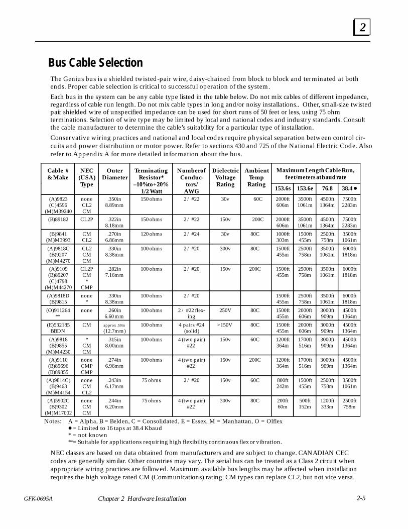
Bus Cable SelectionThe Genius bus is a shielded twisted-pair wire, daisy-chained from block to block and terminated at bothends. Proper cable selection is critical to successful operation of the system.
Each bus in the system can be any cable type listed in the table below. Do not mix cables of different impedance,regardless of cable run length. Do not mix cable types in long and/or noisy installations.. Other, small-size twistedpair shielded wire of unspecified impedance can be used for short runs of 50 feet or less, using 75 ohmterminations. Selection of wire type may be limited by local and national codes and industry standards. Consultthe cable manufacturer to determine the cable’s suitability for a particular type of installation.
Conservative wiring practices and national and local codes require physical separation between control cir-cuits and power distribution or motor power. Refer to sections 430 and 725 of the National Electric Code. Alsorefer to Appendix A for more detailed information about the bus.
Cable #& Make
NEC(USA)T
OuterDiameter
Terminating Resistor*
10%t +20%
Number ofConduc-
t /
DielectricVoltageR ti
AmbientTempR ti
Maximum Length Cable Run, feet/meters at baud rate
Type –10%to+20%1/2 Watt
tors/AWG
Rating Rating153.6s 153.6e 76.8 38.4
(A)9823(C)4596
(M)M39240
noneCL2CM
.350in8.89mm
150 ohms 2 / #22 30v 60C 2000ft606m
3500ft1061m
4500ft1364m
7500ft2283m
(B)89182 CL2P .322in8.18mm
150 ohms 2 / #22 150v 200C 2000ft606m
3500ft1061m
4500ft1364m
7500ft2283m
(B)9841(M)M3993
CMCL2
.270in6.86mm
120 ohms 2 / #24 30v 80C 1000ft303m
1500ft455m
2500ft758m
3500ft1061m
(A)9818C(B)9207
(M)M4270
CL2CMCM
.330in8.38mm
100 ohms 2 / #20 300v 80C 1500ft455m
2500ft758m
3500ft1061m
6000ft1818m
(A)9109(B)89207(C)4798
(M)M44270
CL2PCM
*CMP
.282in7.16mm
100 ohms 2 / #20 150v 200C 1500ft455m
2500ft758m
3500ft1061m
6000ft1818m
(A)9818D(B)9815
none*
.330in8.38mm
100 ohms 2 / #20 1500ft455m
2500ft758m
3500ft1061m
6000ft1818m
(O)911264**
none .260in6.60 mm
100 ohms 2 / #22 flex-ing
250V 80C 1500ft455m
2000ft606m
3000ft909m
4500ft1364m
(E)532185BBDN
CM approx .50in
(12.7mm)100 ohms 4 pairs #24
(solid)>150V 80C 1500ft
455m2000ft606m
3000ft909m
4500ft1364m
(A)9818(B)9855
(M)M4230
*CMCM
.315in8.00mm
100 ohms 4 (two pair)#22
150v 60C 1200ft364m
1700ft516m
3000ft909m
4500ft1364m
(A)9110(B)89696(B)89855
noneCMPCMP
.274in6.96mm
100 ohms 4 (two pair)#22
150v 200C 1200ft364m
1700ft516m
3000ft909m
4500ft1364m
(A)9814C)(B)9463
(M)M4154
noneCMCL2
.243in6.17mm
75 ohms 2 / #20 150v 60C 800ft242m
1500ft455m
2500ft758m
3500ft1061m
(A)5902C(B)9302
(M)M17002
noneCMCM
.244in6.20mm
75 ohms 4 (two pair)#22
300v 80C 200ft60m
500ft152m
1200ft333m
2500ft758m
Notes: A = Alpha, B = Belden, C = Consolidated, E = Essex, M = Manhattan, O = Olflex = Limited to 16 taps at 38.4 Kbaud * = not known**= Suitable for applications requiring high flexibility, continuous flex or vibration.
NEC classes are based on data obtained from manufacturers and are subject to change. CANADIAN CECcodes are generally similar. Other countries may vary. The serial bus can be treated as a Class 2 circuit whenappropriate wiring practices are followed. Maximum available bus lengths may be affected when installationrequires the high voltage rated CM (Communications) rating. CM types can replace CL2, but not vice versa.

2
2-6 Series 90 -30 Enhanced Genius Communications Module User’s Manual –July 1997
GFK-0695A
Using Other Cable Types The cable types listed in the preceding table are recommended for use. If the cable typeslisted above are not available, the cable selected must meet the following guidelines.
1. High quality construction. Most important is uniformity of cross section along thelength of the cable. Poor quality cable may cause signal distortion, and increase thepossibility of damage during installation.
2. Precision-twisted shielded wire of EIA RS422 standard type, having a uniformnumber of twists per unit of length. In a catalog, this type of cable may also be listedas twinaxial cable, data cable, or computer cable.
3. Relatively high characteristic impedance; 100 to 150 ohms is best; 75 ohms is theminimum recommended.
4. Low capacitance between wires, typically less than 20pF/foot (60pF/meter). Thismay be accomplished by inner dielectrics of foamed type, usually polypropylene orpolyethylene, having a low dielectric constant. Alternatively, the conductors may bespaced relatively far apart. Lower impedance types have smaller cross–sections, andprovide easier wiring for shorter total transmission distances.
5. Shield coverage of 95% or more. Solid foil with an overlapped folded seam and drainwire is best. Braided copper is less desirable; spiral wound foil is least desirable.
6. An outer jacket that provides appropriate protection, such as water, oil, or chemicalresistance. While PVC materials can be used in many installations, Teflon,polyethelene, or polypropylene are usually more durable.
7. Electrical characteristics: cable manufacturers’ information about pulse rise time andNRZ data rate is useful for comparing cable types. The Genius bit consists of threeAC pulses; the equivalent NRZ bit rate is about three times as great.
For assistance in selecting a cable type, please consult your local GE Fanuc application engineer.
Bus Length
The maximum bus length for shielded, twisted-pair cable is 7500 feet. Some cable typesare restricted to shorter bus lengths. If the application requires greater bus length, fiberoptics cable and modems can be used. For more information, see the Genius I/O Systemand Communications Manual.
Baud Rate Selection
The bus length determines which baud rate may be selected. A Genius bus can operateat one of four baud rates: 153.6 Kbaud standard, 153.6 Kbaud extended, 76.8 Kbaud, or38.4 Kbaud. The baud rate selected should be indicated on all devices, especially ifdifferent busses in the facility use different baud rates. The baud rate must be configuredusing a Hand-held Programmer or the system configuration software.
Note that in noisy environments, 153.6 Kbaud extended provides improved noiseimmunity with little effect on bus scan time. If a system is experiencing excessiveblinking of the bus controller’s COMM OK light, or if the I/O blocks’ I/O Enabled LEDsgo off frequently, 153.6 Kbaud extended should be used.

2
2-7GFK-0695A Chapter 2 Hardware Installation
Bus Installation
The Genius bus is connected to the terminal assembly on the front of the GCM+module. For the GCM+ module, these terminals have the following assignments:
a45138
OK
COM
ENHANCED
GENIUS
COMM
ÎÎÎÎÎÎÎÎÎÎÎÎÎÎÎÎÎÎÎÎÎÎÎÎÎÎÎÎÎÎÎÎÎÎÎÎÎÎÎÎÎÎÎÎÎÎÎÎÎÎÎÎÎÎÎÎÎÎÎÎÎÎÎÎÎÎÎÎÎÎÎÎÎÎÎÎÎÎ
GENIUS
COMMUNICATIONS
MODULE1
3
2
5
6
7
8
9
10
11
12
13
14
15
16
17
18
19
20
4
44A729182–016R02FOR USE WITH
IC693CMM301 / 302
SER
1
SER
2
SHD
IN
SHD
OUT
Connection can be made to any of the terminals in a group. The cable is routed to andfrom the terminals via the bottom of the Terminal Assembly cavity.
Using the cable type selected for the application, connect the Serial 1 terminals ofadjacent devices and the Serial 2 terminals of adjacent devices. Connect Shield In to theShield Out terminal of the previous device. Connect Shield Out to the Shield In terminalof the next device. For the first device on the bus, Shield In is not connected. For the lastdevice on the bus, Shield Out is not connected.
a43391FIRST
DEVICE
SHIELD
OUT
SHIELD
IN
SERIAL
2
SERIAL
1
R
SHIELD
OUT
SHIELD
OUT
LASTDEVICE
SHIELD
OUT
R
ÎÎ
ÎÎÎÎ
ÎÎÎÎ
ÎÎ
Î
ÎÎ
Î
Î
ÎÎ
Î
Î
ÎÎ
Î
Î Î
ÎÎ
ÎÎ
ÎÎ
SHIELD
IN
SERIAL
2
SERIAL
1
SHIELD
IN
SERIAL
2
SERIAL
1
SHIELD
IN
SERIAL
2
SERIAL
1
Each terminal will accept up to one AWG #14 wire or two AWG #16 wires using ring orlug–type connectors.
The bus shield wires are not insulated; do not permit them to touch other wires orterminals. The use of spaghetti tubing for this purpose is recommended.

2
2-8 Series 90 -30 Enhanced Genius Communications Module User’s Manual –July 1997
GFK-0695A
Serial Wire ConnectionsThe Serial 1 and Serial 2 terminals are interconnected on the circuit board, not on theterminal strip. Incoming and outgoing signal wire pairs can be connected to either oneor two Serial 1 or Serial 2 terminals:
12
34
5
Serial 1terminals
Serial 1signal wires
jumper
12
34
5
Serial 1terminals
Serial 1signal wires
Signal Wires Connectedto One Terminal
Signal Wires Connectedto Two Terminals
If you are connecting two signal wires to the same terminal, use spade or lug–typeconnectors, or twist the exposed ends of the wires together before inserting them. Thiswill allow future removal of the Terminal Assembly without disrupting other devices onthe bus (see Module Removal, in this section).
If you are connecting two signal wires to separate terminals, install a jumper betweenthe two terminals as shown on the right above. Failure to install the jumper will causethe entire bus to be disrupted whenever the faceplate is removed.
Terminating the BusThe bus must be terminated at both ends by its characteristic impedance. The list ofcable types in chapter 3 includes the termination requirements for each cable type. If theGCM+ is at the end of the bus, install a resistor of the appropriate impedance across itsSerial 1 and Serial 2 terminals as shown below.
If you need to install the terminating resistor across different terminals than those usedfor the signal wires, attach jumper wires between the signal wire terminals and theresistor terminals to prevent the bus from becoming unterminated if the TerminalAssembly is removed. Failure to do so will cause the entire bus to be disrupted wheneverthe faceplate is removed.
1
10
Signal Wires and Resistor Connectedto Different Terminals1
23
45
Serial 1 and 2 terminals
Serial 1signal wire
Signal Wires and Resistor Connectedto Same Terminals (preferred)
10
98
76
Serial 2signal wire
3
5Serial 1
signal wire
9
76
Serial 2signal wire
resistor
resistor
jumpers
Serial 1 and 2 terminals

2
2-9GFK-0695A Chapter 2 Hardware Installation
Wiring Guidelines
Four types of wiring may be encountered in a typical factory installation:
1. Power wiring – the plant power distribution, and high power loads such as high horse-power motors.
2. Control wiring – usually either low voltage DC or 120 VAC of limited energy rating.Examples are wiring to start/stop switches, contactor coils, and machine limit switches.This is generally the interface level of the Genius discrete I/O.
3. Analog wiring – transducer outputs and analog control voltages.
4. Communications and signal wiring – the communications network that ties everythingtogether, including computer LANs, MAP, and the Genius communications bus.
These four types of wiring should be separated as much as possible to reduce the hazardsfrom insulation failure, miswiring, and interaction (noise) between signals. A typical PLCsystem may require some mixing of the latter three types of wiring, particularly in crampedareas inside motor control centers and on control panels. In general, it is acceptable to mix theGenius bus cable with the I/O wiring, as well as associated control level wiring. All noisepickup is cumulative, depending on both the spacing between wires and the distance spanthey run together. I/O wires and Genius bus cable can be placed randomly in a wiring troughfor lengths of up to 50 feet. If wiring is cord-tied (harnessed), do not include the bus cable inthe harness, since binding wires tightly together can damage some cable types.
Wiring external to equipment and in cable trays should be separated following NEC practices.
Lightning Transient Suppression
Running the bus cable outdoors or between buildings may subject it to lightningtransients beyond the 1,500 volt transient rating of the system. Installing cableunderground reduces the probability of a direct lightning strike. However, buried cablescan pick up hundreds of amperes of current when lightning contacts the ground nearby.
Therefore, it is important to protect the installation by including surge protectors onunderground data lines. The cable shields should be grounded directly. Surgesuppressors and spark gaps should be used to limit the voltage that might appear on thesignal lines. It is recommended to install two (only) silicon surge suppressors or sparkgaps to control transients of 1 to 25 Kilovolts from 100 to 1000 amps or more. Thesedevices should be installed close to the entrance of the bus to the outdoors.
Silicon Surge Suppressors are available many sources, including Clare/GeneralInstruments and Motorola, For information about this product, in the US contact LucasIndustries Incorporated, 5500 New King Street, Troy, Michigan 48098. Spark gaps areavailable from Clare. Refer to the vendor’s literature for installation details.
In extreme situations such as totally-isolated power systems, additional protectionagainst lightning damage should be provided by adding surge suppressors for groups ofI/O blocks. Such suppressors should be installed from incoming power leads to ground(enclosure baseplate/block case where leads enter the enclosure).
A device specifically designed to protect the Genius bus is available from CONTROLTECHNOLOGY, 835 Hwy 90, Hancock Square Suite 10 (P. O. Box 2908), Bay Saint Louis, MS39520. (tel 601 466– 4550, fax 601 466– 4553). Contact them for application information. Thedevide must be used in combination with power line suppression to fully protect thesystem.

2
2-10 Series 90 -30 Enhanced Genius Communications Module User’s Manual –July 1997
GFK-0695A
Installing a Hand-held Monitor Connector
The GCM+ does not have a built-in connector for a Genius Hand-held Monitor.However, a Hand-held Monitor connector can be added directly to the serial bus at anylocation.
The unit shown below (catalog number 44A736310-001-R001) provides a Hand-heldMonitor connector and serial bus terminals in a single convenient package.
Hand-held Monitor Connector
Serial Bus Terminals
Panel Mounting Ear2.834 in7.198 cm
1.673 in4.249cm
.5 in1.27 cm
shown at 100% of actual size
X1
X1 X2
X2 SA SB
SA SBX1 Serial 1X2 Serial 2SA Shield InSB Shield Out
46357
Mounting the HHM Connector
This unit can be easily mounted on a rail such as a standard 35mm or 15mm DIN rail.The panel-mounting ears are not used if the unit is installed on a DIN rail.
35mm DIN rail
(Removable) DIN railMounting Feet
side view: shown at 50% of actual size
46358
Alternatively, it can be installed directly on a panel using screws through its mountingears. The DIN rail feet on the back of the unit are removed when the unit ispanel-mounted.

2
2-11GFK-0695A Chapter 2 Hardware Installation
Making the Bus Connections
The Hand-held Monitor connector has two sets of terminals; one for incoming cable andthe other for outgoing cable.
Connect the Serial 1, Serial 2, and Shield In terminal of either connector to the previousdevice. Connect the Serial 1, Serial 2, and Shield In terminal of the other connector to thenext device.
The following illustration shows connections for incoming and outgoing serial bus cable.As with other devices, the HHM connector can be at either end of its bus. If it is, therewill only be one bus cable attached.
X1
X1 X2
X2 SA SB
SA SB
X1 Serial 1X2 Serial 2SA Shield InSB Shield Out
Bus In
Bus Out
As with other devices, if the Hand-held Monitor Connector is at either end of its bus,install an appropriate terminating resistor across the Serial 1 and Serial 2 terminals.
2
2-12 Series 90 -30 Enhanced Genius Communications Module User’s Manual –July 1997
GFK-0695A
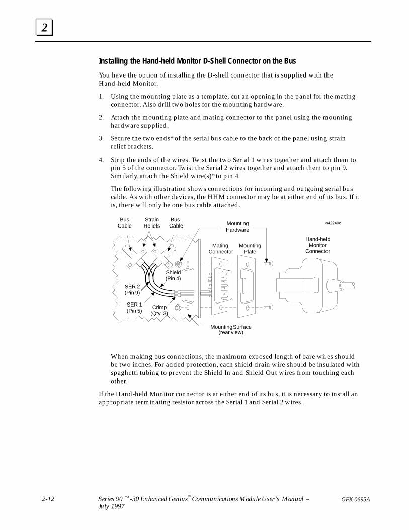
Installing the Hand-held Monitor D-Shell Connector on the Bus
You have the option of installing the D-shell connector that is supplied with theHand-held Monitor.
1. Using the mounting plate as a template, cut an opening in the panel for the matingconnector. Also drill two holes for the mounting hardware.
2. Attach the mounting plate and mating connector to the panel using the mountinghardware supplied.
3. Secure the two ends* of the serial bus cable to the back of the panel using strainrelief brackets.
4. Strip the ends of the wires. Twist the two Serial 1 wires together and attach them topin 5 of the connector. Twist the Serial 2 wires together and attach them to pin 9.Similarly, attach the Shield wire(s)* to pin 4.
The following illustration shows connections for incoming and outgoing serial buscable. As with other devices, the HHM connector may be at either end of its bus. If itis, there will only be one bus cable attached.
MountingHardware
ÎÎÎ
ÎÎÎÎÎÎÎÎÎ
ÎÎÎÎÎÎ
Î
ÎÎ
BusCable
Bus Cable
StrainReliefs
Shield(Pin 4)
Mounting Surface(rear view)
MountingPlate
Hand-heldMonitor
Connector
a42240c
SER 1(Pin 5)
Crimp(Qty. 3)
Mating Connector
SER 2(Pin 9)
When making bus connections, the maximum exposed length of bare wires shouldbe two inches. For added protection, each shield drain wire should be insulated withspaghetti tubing to prevent the Shield In and Shield Out wires from touching eachother.
If the Hand-held Monitor connector is at either end of its bus, it is necessary to install anappropriate terminating resistor across the Serial 1 and Serial 2 wires.

3section level 1 figure bi level 1 table_big level 1
3-1GFK-0695A
Chapter 3 Operation & Timing
This chapter explains:
How the GCM+ sends and receives global data.
What happens to global data if some communications stop.
Application programming needed for global data.
The relationship between the bus scan and the CPU sweep.
How other devices handle global data received from the GCM+.
How to estimate bus scan time.
How to estimate data response time.
How to avoid unnecessarily slowing down both the CPU sweep time and the scantime of the Genius bus.
How the GCM+ Handles Global Data
The GCM+ can send global data to all the other global Genius devices on the bus. It canalso automatically pass to the CPU any global data that has been sent by any otherdevices on the same bus.
Global data can be sent from and received into the following memories in the Series90–30 PLC: %G, %I, %Q, %AI, %AQ, and %R. Status data uses %I memory.

3
3-2 Series 90 -30 Enhanced Genius Communications Module User’s Manual –July 1997
GFK-0695A
GCM+ Receives Global DataThe GCM + passes to the CPU global data from all devices for which a length has beenconfigured.
In the following example, two devices (at Bus Addresses 18 and 22) send globaldata on the bus. Each module broadcasts its global data while it has the bustoken. The global data is received by a GCM+ module in a Series 90–30 PLC(#20 in the diagram).
GCM+
SBA #18 SBA #22SBA #20
Global datafrom SBA #22
Global datafrom SBA #22
Series 90–30Memory
%G, %I,%Q, %AI,%AQ, %R
The GCM+ module stores the global data it receives. When the Series 90–30 CPUexecutes the input update portion of its sweep, it reads both global data and status bits(see below) from the GCM+.
In this example, the PLC CPU copies global data from the GCM+ into thememory locations configured for the devices at Bus Addresses 18 and 22.
GCM+
SBA #18 SBA #22SBA #20
Series 90–30Memory
%G, %I,%Q, %AI,%AQ, %R
What Happens If Incoming Global Data StopsAs part of the GCM+ configuration a data default selection (OFF or Hold Last State)must be configured. If the GCM+ stops receiving global data from any device(s) forwhich a global data length has been configured, the GCM+ sets the correspondingmemory locations to the selected default. If the default is OFF, the GCM+ supplies 0s forthe missing data. If the default is Hold, the GCM+ continues to supply the last set ofvalid data it received.
Status BitsThe GCM+ maintains a status bit for every potential bus device. Those bits are set to 1for every device that sends global data. If the GCM+ does not receive, or stops receiving,communications from any device, its bit is set to 0. In addition, it defaults the data asdescribed above. The configuration supplied to the GCM+ must provide a location in %Iin which to place the 32 status bits. The status bits are updated every PLC sweep.

3
3-3GFK-0695A Chapter 3 Operation & Timing
GCM+ Sends Global DataIf there is an application program running in the 90–30, it executes before the PLC CPUupdates outputs. During the output portion of the sweep. if the GCM+ is configured tosend global data, the PLC CPU also writes the content of the selected memory locationto the GCM+.
Continuing the same example, the CPU sends new global data to its GCM+from the memory location configured for Bus Address 20.
GCM+
SBA #18 SBA #22SBA #20
Series 90–30Memory
%G, %I,%Q, %AI,%AQ, %R
The GCM+ module stores this data until it receives the bus token. At that time, itbroadcasts the global data to all the other devices on the bus.
In the example system, both Bus Addresses 18 and 22 will receive the global datasent from Bus Address 20:
GCM+
SBA #18 SBA #22SBA #20
Series 90–30Memory
%G, %I,%Q, %AI,%AQ, %R
Global datafrom SBA #20
What Happens If the CPU Stops Supplying Global DataAs mentioned above, a data default of OFF or Hold Last State must be selected. If theGCM+ stops being scanned by the Series 90–30 PLC CPU, it defaults its outgoing globaldata. If the default is OFF, it sends all 0s. If the default is Hold, it continues to send thelast set of valid data it received from the CPU.
Global Data Without an Application ProgramThe Series 90–30 can transmit and receive global data with or without running anapplication program. Configuring I/O modules in the Series 90–30 to have the samereference addresses used for global data allows the I/O modules to effectively exchangeI/O data with another device on the bus. Thus, where it is desired to set up the Series90–30 PLC without a program, incoming data to the GCM+ will be mapped to %Q and%AQ (where output modules are also mapped) and outgoing global data will bemapped to %I or %AI (where input modules are also mapped).

3
3-4 Series 90 -30 Enhanced Genius Communications Module User’s Manual –July 1997
GFK-0695A
How Other Devices Handle GCM+ Global Data
Global data sent by a GCM+ can be received by any other GCM+, bus controller, PCIM,QBIM, or GCM on the bus. All of the devices will receive the same global data messagefrom the GCM+. How each type of device handles the message is summarized below.
A GCM+ or bus controller in another Series 90–30 PLC places the datain the memory location specified when that GCM+ or bus controller isconfigured. If the GCM+ or bus controller does not need all of the data,a message offset and length can be specified.
The Series 90–30 Genius Communications Module (GCM) uses specific%G memory locations for global data. It places incoming global data inthe %G memory location corresponding to Device Number (16–23) ofthe device that sent the data. The GCM will not receive global data sentfrom SBAs 0 to 15 or 24 to 31.
The Series 90–70 PLC places incoming global data into the memorylocation selected during configuration of its bus controller.
If a Series Six Reference is specified during GCM+ configuration, anySeries Six and/or Series Five PLC on the bus will automatically receive allglobal data from the GCM+ and place it in that register location.
See Series Six PLC.
Data from the GCM+ is placed into the PCIM or QBIM Input TableSegment corresponding to the Bus Address of the GCM+. Thecomputer ’s application program is responsible for transferring globaldata between the CPU and the PCIM or QBIM.
I/O blocks (controlled by another host) can be present on the bus, butthey cannot receive global data.
Series 90–30PLC GCM+Module orBus Control-ler
Series 90–30PLC GCMModule
Series 90–70PLC
Series SixPLC
Series FivePLC
Computer
I/O Blocks

3
3-5GFK-0695A Chapter 3 Operation & Timing
Timing Considerations
Communications on the Genius bus occur by a method called “token passing”. Thedevices on the bus pass an implicit token, which rotates among the devices in sequencefrom bus address 0 to bus address 31. Unused bus addresses (SBAs) are passed withvery slight delays. This sequence is called a bus scan. After device 31 has had its turn,the scan restarts at device 0.
a43393
TOKEN PATH
DEVICESON THE
BUS0 16 23 31
Each device on the bus can listen to messages at all times (not just when it has thetoken). A GCM+ module listens to all broadcast messages. These are messages that aresent to all devices on the bus. Global data is a type of broadcast message.
While each device holds the token, it can send messages. To end its turn, thetransmitting device sends one specific broadcast message which acts as a sign–offmessage, and the token passes to the next device.
Bus Scan Time and CPU Sweep TimeGlobal Data adds to both the CPU sweep time in the Series 90–30 and to the scan timeof the Genius bus. You can estimate the CPU sweep time and bus scan time added byglobal data, and the time it can take for a Series 90–30 PLC to send global data and thenreceive a response based on that data.
If CPU sweep time is slower than bus scan time, it is possible that some incoming globaldata might change before it is picked up by the CPU. It is important to be sure that thedata will not be sent so briefly that it will be missed.
If program execution time is faster than bus scan time, the CPU may process the samedata repeatedly. Also, if output data changes too quickly, some outputs may changebefore they are sent out on the Genius bus.
The Series 90-30 PLC Installation Manual (GFK-0356) explains how you can estimate busscan time.

3
3-6 Series 90 -30 Enhanced Genius Communications Module User’s Manual –July 1997
GFK-0695A
Bus Scan Time for Global Data
The minimum amount of time required for the token to make a complete bus rotation is3mS. This minimum time limit is imposed by the GCM+ and other types of businterface modules. The maximum possible bus scan time is 400mS, but this will never bereached under normal circumstances.
The presence of other PLCs, a host computer, I/O blocks, or datagrams on the bus addsto the bus scan time (although the time required for each individual messagetransmission remains the same). Using one of the slower baud rates also increases busscan time. The scan time increase from 153.6 Kbaud standard to 153.6 Kbaud extended isslight. But scan time is about twice as long at 76.8 Kbaud and four times as long at 38.4Kbaud.
Estimating Bus Scan TimeIf you want to estimate bus scan time, follow the instructions below for GCM+ modules.If the bus also has other types of controllers or Genius I/O blocks, you will needadditional information from the Genius I/O System User’s Manual.
1. First, add up the time needed to service all 32 possible bus addresses (includingunused bus addresses), at the bus baud rate. See the table below.
Device TypeContribution time in mS at each baud rate
Device Type153.6 Kb std 153.6 Kb ext 76.8 Kb 38.4 Kb
GCM+ 0.586 0.658 1.324 2.655
Unused Bus Address 0.026 0.052 0.104 0.208
2. Next, find the total amount of global data transmitted each bus scan. For example,if two GCM+ modules each send a 24–byte global data message and there is noother global data on the bus, the total is 48 bytes.
3. Multiply the total amount of global data by the transmission rate:
0.0715ms per byte for 153.6 Kbaud (either standard or extended)0.143ms per byte for 76.8 Kbaud0.286ms per byte for 38.4 Kbaud
Example
A bus has eight GCM+ modules and no other devices. Each GCM+ sends 24 bytes ofglobal data. The baud rate 153.6 Kbaud standard.
8 GCM+ modules (8 x 0.586) 4.688ms24 unused Device Numbers (24 x 0.026) 0.624ms8 global data messages, 24 bytes each ((8 x 24) x 0.0715) 13.728mS
Total bus scan time = 19.040mS
Reducing Bus Scan TimeBus scan time can be shortened by reducing the number of devices on the bus, reducingthe amount of global data transmitted, or both.

3
3-7GFK-0695A Chapter 3 Operation & Timing
Estimating Data Response Time
If you want to find out approximately how long it will take for one module to sendglobal data to another and to receive a response based upon that data, add together themaximum times that may be required for each portion of the input to output cycle.
GCM+ GCM+
BUS
DataOut
DataOut
DataIn
DataIn
CPU2CPU1
ProgramExecution
ProgramExecution
Tcpu Tcpu
Tmsg 1–2
Tmsg 2–1
The equation to use when calculating response time is:
2(Tcpu 1 ) + (Tmsg 2 – 1 + Tmsg 1 – 2 ) + 2(Tcpu 2 ) = response time
Bus Scan Time (Tmsg)Whenever a GCM+ gets its turn on the bus, it obtains the latest global data from theSeries 90–30 PLC CPU, then transmits that data on the bus. An application programnormally will process the incoming global data before preparing a response. In the worstcase, this will result in the response being sent on a separate Genius bus scan. Thus, fromCPU1 to CPU2 there is a delay of Tmsg1– 2 and from CPU2 to CPU1 there is a delay ofTmsg2– 1. Calculate Tmsg for a GCM+ by going through steps 1, 2, and 3 on theprevious page. Don’t include unused bus addresses.
CPU Time (Tbus) for Each CPUA GCM+ module stores incoming global data where it can be accessed by theapplication program currently executing in the CPU. If the CPU services the moduleshortly after it receives new global data, the data is read into CPU memory quickly.However, if the GCM+ module has just been serviced by the CPU, the global data won‘tbe read until the next sweep. The worst–case delay is therefore Tcpu.
If the application program will send global data in response to global data it hasreceived, one additional CPU sweep is needed for the application program to processthe data and update the GCM+. Again, this represents a delay of Tcpu, Total delay timewithin each CPU is 2Tcpu.

4section level 1 figure bi level 1 table_big level 1
4-1GFK-0695A
Chapter 4 Configuration
This chapter describes:
Configuration parameters of the GCM+
Configuration steps for the GCM+ using a Series 90-30 Hand-held Programmer
The GCM+ must be physically present to be configured by a Hand-held Programmer(HHP). It does not have to be present if it will be configured using the systemconfiguration software. The HHP may be used to enter, change, or remove a GCM+configuration. The HHP will work whether the Series 90-30 was previously configuredwith the system configuration software to include a GCM+ or not. Note that a GeniusHand-held Monitor cannot be used to configure a GCM+.
Initial ConfigurationAn unconfigured GCM+ may be installed in a Series 90-30 PLC and connected to theGenius bus. Until such time as it is configured, it will not communicate on the Geniusbus and will not exchange any data with its host CPU. To configure the GCM+, the CPUmust be in Stop mode.
Global Data Transmissions during ReconfigurationConfiguration data is stored by the PLC. Once defined, the configuration cannot bealtered without stopping the PLC. Note that placing the PLC in Stop mode forreconfiguration does not stop the GCM+ from sending global data. The content of the datadepends on the modules’s configured data default. If its data default is OFF, the GCM+sends all 0s each bus scan. If its data default is Hold Last State, the GCM+ sends a copy ofthe last valid set of data it received from the CPU.
You can prevent the GCM+ sending default data during reconfiguration by temporarilyremoving it from the bus. The bus wiring must have been installed as described in chapter 2so that the bus is not “broken” by removal from the GCM+ . The recommendedconfiguration sequence is:
disconnect the bus
place the PLC in Stop mode
change the configuration
return to Run mode
reconnect the bus
After you finish reconfiguration and return to Run mode, the GCM+ starts sending newglobal data as soon as it is supplied by the PLC CPU.
4
4-2 Series 90 -30 Enhanced Genius Communications Module User’s Manual –July 1997
GFK-0695A
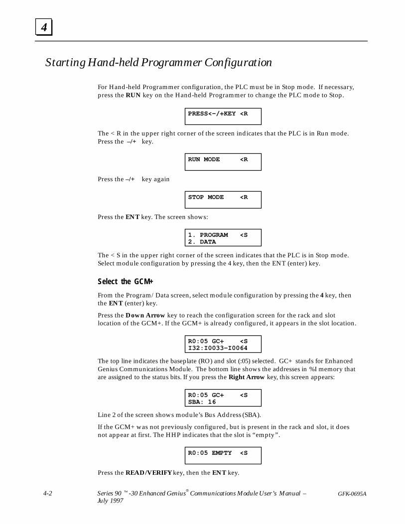
Starting Hand-held Programmer Configuration
For Hand-held Programmer configuration, the PLC must be in Stop mode. If necessary,press the RUN key on the Hand-held Programmer to change the PLC mode to Stop.
PRESS<–/+KEY <R
The < R in the upper right corner of the screen indicates that the PLC is in Run mode.Press the –/+ key.
RUN MODE <R
Press the –/+ key again
STOP MODE <R
Press the ENT key. The screen shows:
1. PROGRAM <S2. DATA
The < S in the upper right corner of the screen indicates that the PLC is in Stop mode.Select module configuration by pressing the 4 key, then the ENT (enter) key.
Select the GCM+
From the Program/Data screen, select module configuration by pressing the 4 key, thenthe ENT (enter) key.
Press the Down Arrow key to reach the configuration screen for the rack and slotlocation of the GCM+. If the GCM+ is already configured, it appears in the slot location.
R0:05 GC+ <SI32:I0033–I0064
The top line indicates the baseplate (RO) and slot (:05) selected. GC+ stands for EnhancedGenius Communications Module. The bottom line shows the addresses in %I memory thatare assigned to the status bits. If you press the Right Arrow key, this screen appears:
R0:05 GC+ <SSBA: 16
Line 2 of the screen shows module’s Bus Address (SBA).
If the GCM+ was not previously configured, but is present in the rack and slot, it doesnot appear at first. The HHP indicates that the slot is “empty”.
R0:05 EMPTY <S
Press the READ/VERIFY key, then the ENT key.

4
4-3GFK-0695A Chapter 4 Configuration
HHP Error MessagesThe Hand-held Programmer will display a message if you make an error duringconfiguration, or if the GCM+ is not present or not communicating with the host PLC.
REF ER May indicate either of the following:
A. The reference address assigned to that SBA exceeds thereference limit for the PLC model.
B. The SBA message offset plus the length of the referenceassigned to the SBA exceed 128 bytes.
REF ADJ May indicate either of the following:
A. References have been adjusted (rounded) down to a byteboundary.
B. For discrete references, the reference length for the SBA hasbeen rounded up to a byte boundary.
GCM ERR May indicate either of the following:
A. Too many GCM+ modules have been configured (the limit is 3).
B. You have tried to configure a GCM+ module and a GCMmodule in the same PLC. The GCM+ cannot be installed inthe same PLC as a GCM module.
IOM ERR The GCM+ module is not available.
I/O ERR You have assigned reference addresses that overlap referencesalready assigned.
DAT ERR A parameter (such as the Series Six reference address) is out ofbounds.

4
4-4 Series 90 -30 Enhanced Genius Communications Module User’s Manual –July 1997
GFK-0695A
Configurable Features of the GCM+
Configuration supplies the following setup information for a GCM+:
Parameter Default Choices Comments
Slot numberof the GCM+
none Any Series 90-30 rack slot
SBA 16 0 – 31 Bus Address
Drop ID 33 16 – 254. Optional. Used with the ReportFaults feature.
Baud Rate 153.6 Kb st. 153.6 Kb standard or extended,76.8 KB, or 38.4 Kb.
All devices on the bus must usethe same baud rate.
Data Default Off Off or Hold Last State Determines data content if com-munications are lost.
Report Faults No Yes or No Optional. Used to send FaultReports to a Series 90-70 PLC.
S6 Reference 0 1–16,383 Optional. For sending globaldata to a Series Six or SeriesFive PLC.
Status %I0001 Any available %I reference inhost.
Requires 32–bit memory space.
Starting Ref-erence
see text. Any available %I, %Q, %G, %AI,%AQ, or %R reference in host.
One table memory type permessage.
ReferenceLength
0 0 – 64 words or 0 to 1024 bits inselected host memory.
A length must be specified toexchange global data.
Message Buff-er Byte Offset
0 0 – 128 bytes. Optional. Used to skip the startof an incoming global data mes-sage. The configured offsetplus length should not exceedthe end of the message.
Status
This is the beginning address of a 32–bit status area in the %I memory of the Series90-30 PLC where the GCM+ can locate status information.
Hand-held Programmer Configuration
R0:05 GC+ <SI32:I _
Enter the beginning reference in %I memory for the GCM+ module’s 32 status bits. It isnot necessary to enter leading zeros. After entering the number, press the Enter key. TheHHP displays the range of selected status bit addresses. For example:
R0:05 GC+ <SI32:I0001–I0032
Press the Right Arrow key to go to the next configuration screen.

4
4-5GFK-0695A Chapter 4 Configuration
Bus Address (Device Number)Each Genius communications bus can serve up to 32 devices, which are identified by aBus Address (sometimes called a Device Number) from 0 to 31. By convention, certainnumbers are associated with specific types of devices. For example, Bus Address 0 isnormally used for a Genius Hand-held Monitor. The Series 90-70 PLC and the Series SixPLC use Bus Addresses 30 and 31 for Bus Controllers in a backup (redundancy) type ofsystem. The Series 90-30 Genius Communications Module, an earlier version of theGCM+, uses Bus Addresses 16 through 23 for global data.
Hand-Held Programmer Configuration
If the Bus Address shown is not correct for this GCM+, enter the new number from thekeypad. Press the ENT key to display the new Bus Address. For example:
R0:05 GC+ <SBUS ADDR: 17
To continue configuring the same module, press the Right Arrow key.
Baud Rate
All devices on a bus must be configured to use the same baud rate: 153.6 Kbaudstandard, 153.6 Kbaud extended, 76.8 Kbaud, or 38.4 Kbaud. The module is set to operateat 153.6 Kbaud standard when shipped from the factory.
Baud rate must be selected on the basis of cable type (see the table in chapter 2) and thefollowing considerations.
1. If the cable length is less than 2000 feet, either 153.6 Kbaud standard or 153.6 Kbaudextended can be used. The use of 153.6 Kbaud extended is recommended, especiallyif the system will include a dual bus with Bus Switching Modules.
2. If cable length is between 2000 and 3500 feet, select 153.6 Kbaud extended.
3. If the cable length is between 3500 and 4500 feet, select 76.8 Kbaud.
4. If the cable length is between 4500 and 7500 feet, you must select 38.4 Kbaud. Thisdata rate only supports a maximum of 16 device on the bus.
5. If there are any older Genius products on the bus (catalog numbers IC660CBDnnn,IC660CBSnnn, IC660CBAnnn, IC660HHM500, or IC660CBB900/901), the bus mustbe set up to use 153.6 Kbaud standard.
Hand-Held Programmer Configuration
Pressing the right arrow key once from the Bus Address screen shows thecurrently–configured baud rate. For example:
R0:05 GC+ <SBAUD:153.6KSt
If the baud rate shown is not correct, press the +/– key to change it. When the correctbaud rate appears, press the Enter key then the Right Arrow key to display the nextconfigurable feature of the module.

4
4-6 Series 90 -30 Enhanced Genius Communications Module User’s Manual –July 1997
GFK-0695A
Series Six Reference
This entry can be used to specify a beginning register to be used by a Series Six or SeriesFive PLC for global data received from the GCM+.
All Series Six and Series Five PLCs on the bus will use this reference. The range ofregisters available for global data use is 1 to 16,383. A Series Six or Series Five PLC willfigure out the length automatically and will require this amount of register space forglobal data.
If a previously–configured Series Six or Series Five PLC should no longer receive globaldata from a GCM+, this should be set to 0.
Hand-Held Programmer Configuration
If there is a Series Six or Series Five PLC on the bus that should receive global data fromthe GCM+, enter a register number here.
If a previously–configured Series Six or Series Five PLC should no longer receive globaldata from a GCM+, enter 0.
R0:05 GC+ <SS6 REF:
Data Default
This parameter determines how the GCM+ will respond if it loses communications.Data will either HOLD its last state, or be set to 0 (OFF). If the GCM+ stops beingscanned by the PLC CPU, it applies the data default as outputs. If the GCM+ stopsreceiving data from one or more devices on the bus, it applies the data default for themissing devices as inputs being passed back to the CPU. The same type of default (laststate or zero) is used for both outgoing and incoming data.
If data should hold its last state when communications are lost, select HOLD. If datashould be set to 0, select OFF.
Hand-Held Programmer Configuration
R0:05 GC+ <SDATA DEF:OFF
Press the –/+ key to select OFF or HOLD, then press the ENT key.

4
4-7GFK-0695A Chapter 4 Configuration
Report Faults
The GCM+ can send fault reports that can be read by any Series 90-70 PLC on the samebus (the Bus Controller in the Series 90-70 PLC must be rev. 4.0 or later).
If Fault Reports is set to YES, a Drop ID (see below) must be assigned to the Series 90-30PLC where the GCM+ is located.
If the GCM+ will send fault reports, set Report Faults to YES.
Hand-Held Programmer Configuration
R0:05 GC+ <SREPORT FLTS:NO
Use the –/+ key toggles between YES and NO. Press Entr. Press the Right Arrow key togo to the next item.
Drop ID
A Drop ID must be assigned if a Series 90-70 PLC on the bus will monitor fault reportdiagnostic messages sent by the GCM+.
The Drop ID (a number from 16 to 254) is used to identify the Series 90-30 PLC wherethe fault has occurred. This number must not duplicate one used by another PLC thatsends Fault Reports, or a Remote I/O Scanner, or a device in the 90-70 system that usesSNP communications.
If two GCM+ modules in the same PLC will both send fault reports, configure the sameDrop ID for both.
Hand-Held Programmer Configuration
If there is a Series 90-70 PLC that should receive fault reports from the GCM+, enter aDrop ID for the Series 90-30 PLC where the GCM+ module is located.
R0:05 GC+ <SDROP ID: 33
Press Entr. Press the Right Arrow key to go to the next item.
4
4-8 Series 90 -30 Enhanced Genius Communications Module User’s Manual –July 1997
GFK-0695A
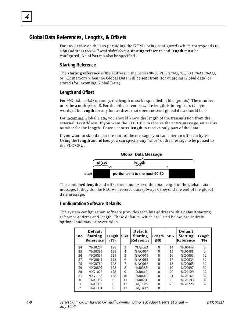
Global Data References, Lengths, & OffsetsFor any device on the bus (including the GCM+ being configured) which corresponds toa bus address that will send global data, a starting reference and length must beconfigured. An offset can also be specified.
Starting Reference
The starting reference is the address in the Series 90-30 PLC’s %G, %I, %Q, %AI, %AQ,or %R memory when the Global Data will be sent from (for outgoing Global data) orstored (for incoming Global Data).
Length and Offset
For %G, %I, or %Q memory, the length must be specified in bits (points). The numbermust be a multiple of 8. For the other memories, the length is in registers (2–bytewords). The length for any bus address that does not send global data should be 0.
For incoming Global Data, you should know the length of the transmission from theexternal Bus Address. If you want the PLC CPU to receive the entire message, enter thisnumber for the length. Enter a shorter length to receive only part of the data.
If you want to skip data at the start of the message, you can enter an offset in bytes.Using the length and offset, you can specify any “slice” of the message to be passed tothe PLC CPU.
length
Global Data Message
offset
portion sent to the host 90-30start
The combined length and offset must not exceed the total length of the global datamessage. If they do, the PLC will receive data (always 0) beyond the end of the globaldata message.
Configuration Software Defaults
The system configuration software provides each bus address with a default startingreference address and length. These defaults, which are listed below, are entirelyoptional and may be overridden.
SBADefaultStarting
ReferenceLength
(F9)SBA
DefaultStarting
ReferenceLength
(F9)SBA
DefaultStarting
ReferenceLength
(F9)
2425262728293031012
%G0257%G0385%G0513%G0641%G0769%G0897%G1025%G1153%AI057%AI059%AI061
128128128128128128128128000
345678910111213
%AI063%AQ057%AQ059%AQ061%AQ063%I0385%I0417%I0449%I0481
%Q0385%Q0417
00000000000
14151617181920212223
%Q0449%Q0481%G0001%G0033%G0065%G0097%G0129%G0161%G0193%G0225
003232323232323232

4
4-9GFK-0695A Chapter 4 Configuration
Hand-Held Programmer Configuration
Configuration is the same for sending or receiving global data.
There are two screens for every bus address from 0 to 31. Press the Right Arrow key toadvance from screen to screen. If you want to go back, use the Left Arrow key. On thescreen that represents the bus address of the GCM+ itself, you will see an asterisk (*) infront of the SBA number. The first of these configuration screens is for bus address 0.
R0:05 GC+ SB00<SIGNORE DEVICE
If you want to skip (“ignore”) any bus address, press the Right Arrow key.
If the GCM+ will receive global data from the device whose bus address is shown in theupper right corner of the screen, or if the GCM+ module’s own bus address is beingdisplayed, enter the memory type (I, Q, G, AI, AQ, or R) where the data will be locatedin the Series 90-30 PLC. Press the ENT key. Example:
R0:05 GC+ SB04>SI _
Press the IAI key once. Enter the number of bits or registers of the global data to be
written or read. For %G, %I, or %Q memory, the number must be a multiple of 8. If itisn’t, the HHP will automatically adjust it. Press ENT.
R0:05 GC+ SB04>SI0040:I_
Enter the beginning reference for the data and press ENT. The HHP displays referencesthat correspond to the starting reference and length you have entered. For example, fora starting reference of 33 and length of 40, the HHP would show:
R0:05 GC+ SB04>SI0040:I0033–0072
Press the Right Arrow key to display the second configuration screen for the same busaddress. For example:
R0:05 GC+ SB04>SMSG OFFS: 0
If the current configuration screen is for the GCM+ module itself, skip to the next busaddress, or exit if you have finished configuring devices.
If the configuration is for a device that will send data to the GCM+, and if the GCM+should read only part of a global data message, but not the beginning, enter an offset,then press the Enter key. The offset is the amount, in bytes, to be skipped at the start ofthe message.
Use the Right Arrow key to continue configuring global data parameters. Skip the busaddresses that don’t correspond to global data devices. It isn’t necessary to go throughall 32 bus devices; when you finish configuring devices, you can exit.

4
4-10 Series 90 -30 Enhanced Genius Communications Module User’s Manual –July 1997
GFK-0695A
Configuration Example 1GCM+ modules in two Series 90-30 PLCs exchange global data with each other. One ofthem also exchanges global data with another Series 90-30 PLC that has an older GeniusCommunications (GCM) Module (IC693CMM301) instead of a GCM+. If there is a GCMon the bus, the following restrictions exist:
1. Any device that communicates with a GCM must use an SBA from 16 to 23.
2. Any device that communicates with a GCM is constrained to send an amount ofdata the GCM can handle. GCM modules can send and/or receive up to a total of 32bytes (256 bits) of global data.
3. As a result, devices that send large amounts of global data should not communicatewith a GCM and so should not use an SBA from 16 to 23 when on a bus whichcontains a GCM.
In this example:
The GCM+ that does not exchange global data with the GCM uses SBA #1. Every busscan, this GCM+ sends 48 bytes of global data from %R memory. The data is receivedby the GCM+ at SBA #20, which is configured to place the data into %R memory. TheGCM module in the third PLC is not capable of receiving the data from SBA #1.
SBA #1 SBA #20 SBA #16
48 bytes
GCMGCM+GCM+
The second GCM+ sends 16 bytes of global data from %G memory. To allow its datato be received by the GCM module, the second GCM+ is assigned SBA #20. TheGCM+ module at SBA #1 places the data into %I memory. The GCM module uses%G memory for all global data.
SBA #1 SBA #20 SBA #16
16 bytes
GCMGCM+GCM+
The GCM module, which uses SBA #16, sends 16 bytes of global data from %Gmemory. Both of the GCM+ modules receive the data and place it in %I memory.
SBA #1 SBA #20 SBA #16
16 bytes
GCMGCM+GCM+

4
4-11GFK-0695A Chapter 4 Configuration
Device SBATransmit: Refs/Bytes
Received from#1: Refs/Bytes
Received from#16: Refs/Bytes
Received from#20:R efs/Bytes
GCM+ 1 %R0001/48 none %I0001/16 %I00017/16GCM+ 20 %G0001/16 %R0001/48 %I0001/16 none
90-30 GCM 16 %G001/16 none none %G129/16
1. Configure the first GCM+ at SBA #1.
2. Configure the baud rate so that all devices operate at the same rate.3. Configure the references, lengths and offsets for global data.
A. On the configuration screen, there is an asterisk (*) beside SBA #1, because it isthe device being configured. Enter the parameters for the data to be transmitted:
Starting Reference %R0001Reference Length 24 registers (=48 bytes)Msg Buffer Byte Offset 0
B. Enter the parameters for the data to be received from GCM+ #20:
Starting Reference %I0001Reference Length 128 bits (==16 bytes)Msg Buffer Byte Offset 0
C. Enter the parameters for the data to be received from the GCM at SBA #16:Starting Reference %I0017Reference Length 128 bits (16 bytes)Msg Buffer Byte Offset 0
D. For all other SBAs on the bus:Starting Reference don’t careReference Length 0 (required)Msg Buffer Byte Offset 0
1. Configure the second GCM+ at SBA #20.2. Configure the baud rate so that all devices operate at the same rate.
3. Configure the references, lengths and offsets for global data.
A. On the configuration screen, there is an asterisk (*) beside SBA #20, because it isthe device being configured. Enter the parameters for the data to be transmitted:
Starting Reference %G0001Reference Length 128 bits (=16 bytes)Msg Buffer Byte Offset 0
B. Enter the parameters for the data to be received from GCM+ #1:
Starting Reference %R0001Reference Length 24 registers (=48 bytes)Msg Buffer Byte Offset 0
C. Enter the parameters for the data to be received from the GCM at SBA #16:
Starting Reference %I0017Reference Length 128 bits (=8 x 16 bytes)Msg Buffer Byte Offset 0
D. For all other SBAs on the bus:
Starting Reference don’t careReference Length 0 (required)Msg Buffer Byte Offset 0
Please see the Genius Communications Module User’s Manual (GFK–0412) if you needmore information about how the GCM is configured, and how it handles global data.
ConfigurationSummary for this Example
Configuration for GCM+ #1
Configuration for GCM+ #20
Configuration for GCM #16

4
4-12 Series 90 -30 Enhanced Genius Communications Module User’s Manual –July 1997
GFK-0695A
Configuration Example 2
There are two Series 90-30 PLCs with GCM+ modules on a bus with a Series 90-70 PLCand a host computer.
SBA #31 SBA #1 SBA #2SBA #29
Both Series 90-30 PLCs send 50 bytes of global data.
Each Series 90-30 PLC listens to 10 bytes of the other’s global data and places thedata into its own %G memory.
SBA #1 SBA #2
First 10 bytesglobal data
The Series 90-70 PLC receives all Global Data from both Series 90-30s. Both sets ofincoming global data are placed into %I memory.
50 bytes
SBA #31 SBA #1 SBA #2
50 bytes global data
The Series 90-70 PLC broadcasts 100 bytes of global data each bus scan. The first 60bytes is for one Series 90-30 PLC and the last 40 bytes is for the other.
60 bytes 40 bytes
SBA #31
global data
Each Series 90-30 PLC reads only the intended portion of the data sent by the 90-70,and discards the rest by using the offset and length parameters.
SBA #1 SBA #2 SBA #1 SBA #2
60 bytesglobal data
offset = 0 bytes 40 bytesglobal data
offset = 60 bytes
The computer acts as a monitor, and reads all global data from the Series 90-30 andSeries 90-70 PLCs, and transmits no global data itself.

4
4-13GFK-0695A Chapter 4 Configuration
Device SBATransmit: Refs/Bytes
Received from#1: Refs/Bytes
Received from#2: Refs/Bytes
Received from#31:R efs/Bytes
GCM+ 1 %I0001/50 none %G0001/10 %Q0001/60GCM+ 2 %I0001/50 %G0001/10 none %Q0001/40
90-70 GBC 31 %Q0001/100 %I1001/50 %I2001/50 nonePCIM 29 none all all all
1. Configure the first GCM+ at SBA #1.2. Configure the baud rate so that all devices operate at the same rate.3. Configure the references, lengths and offsets for global data.
A. On the configuration screen, there is an asterisk (*) beside SBA #1, because it isthe device being configured. Enter the parameters for the data to be transmitted:
Starting Reference %I0001Reference Length 400 bits (=50 bytes)Msg Buffer Byte Offset 0
B. Enter the parameters for the data to be received from GCM+ #2:Starting Reference %G0001Reference Length 80 bits (=10 bytes)Msg Buffer Byte Offset 0 (the first 10 bytes will be received)
C. Enter the parameters for the data to be received from the Series 90-70 PLC’s BusController, at SBA #31:
Starting Reference %Q0001Reference Length 480 bits (=60 bytes)Msg Buffer Byte Offset 0 (the first 60 bytes will be received)
D. For all other SBAs on the bus:Starting Reference don’t careReference Length 0 (required)Msg Buffer Byte Offset 0
1. Configure the second GCM+ at SBA #2.2. Configure the baud rate so that all devices operate at the same rate.3. Configure the references, lengths and offsets for global data.
A. Enter the parameters for the data to be received from GCM+ #1:Starting Reference %G0001Reference Length 80 bits (=10 bytes)Msg Buffer Byte Offset 0 (the first 10 bytes will be received)
B. On the configuration screen, there is an asterisk (*) beside SBA #2, because it isthe device being configured. Enter the parameters for the data to be transmitted:
Starting Reference %I0001Reference Length 400 bits (=50 bytes)Msg Buffer Byte Offset 0
C. Enter the global data reference, length, and offset for the data to be receivedfrom the Series 90-70 PLC’s Bus Controller, at SBA #31:
Starting Reference %Q0001Reference Length 320 bits (=40 bytes)Msg Buffer Byte Offset 60 (the first 60 bytes will be skipped)
D. For all other SBAs on the bus:Starting Reference don’t careReference Length 0 (required)Msg Buffer Byte Offset 0
The PCIM at SBA #29 is set up to handle the three global data messages via itsapplication program. The Series 90-70 PLC at SBA #31 configures GCM+ modules atSBAs #1 and #2, and expects each to send 50 bytes, which it places in 90-70 memory at%I1001–%I1401 and %I2001–%I2401 respectively.
ConfigurationSummary for this Example
Configuration for GCM+ #1
Configuration for GCM+ #2
Configuration for the Other Devices

4
4-14 Series 90 -30 Enhanced Genius Communications Module User’s Manual –July 1997
GFK-0695A
Configuration Example 3
In this example, there are four Series 90-30 PLCs. Each one sends global data from %Qmemory. Each of the other Series 90-30s reads 8 bytes of the global data and places it into%I memory.
SBA #1 SBA #2 SBA #3 SBA #4
8 bytes
8 bytes 8 bytes
This illustration represents the global data transmission for one Series 90-30 PLC. In thesame bus scan, the three other PLCS also send global data the same way.
In this system:
A GCM+ is installed in each Series 90-30 PLC. The GCM+ modules are configuredto use Bus Addresses (SBAs) 1 through 4.
In each Series 90-30 PLC, the first 32 bytes (256 bits) of %I and %Q memory is setaside for global data. The 32 bytes are divided into 4 segments of 8 bytes each; thesegments are organized in ascending order of SBAs.
SBA #1
SBA #2
SBA #3
SBA #4
SBA #1
SBA #2
SBA #3
SBA #4
%Q Memory %I Memory
Thus, each PLC has a segment of its %Q memory set up to convey data to anotherspecific PLC, and a corresponding segment set up in I% to receive data. There is anunused segment in each table, which corresponds to the SBA of that GCM+.
from SBA #1
from SBA #2
SBA #3
from SBA #4SBA #1
to SBA #2
to SBA #3
to SBA #4
to SBA #1
SBA #2
to SBA #3to SBA #4
to SBA #1to SBA #2
to SBA #3
SBA #4
(%I)
(%Q) (%Q) (%Q)

ÉÉÉÉ
ÉÉÉÉÉÉ
ÉÉÉÉÉÉ
ÉÉÉÉÉÉÉÉÉ
ÉÉÉÉ
ÉÉÉÉÉÉ
ÉÉÉÉ
ÉÉÉÉÉÉÉÉÉ
ÉÉÉÉÉÉ
ÉÉÉÉÉÉ
ÉÉÉÉÉÉ
ÉÉÉÉÉÉ
SBA
SBA #1SBA #2SBA #3SBA #4
all others
StartingReference
%Q0001%I0065%I0129%I0193
x
ReferenceLength(bits)2566464640
MessageBuffer Offset
(bytes)x000x
SBA
SBA #1SBA #2SBA #3SBA #4
all others
StartingReference
%I0001%Q0001%I0129%I0193
x
Configuration For SBA #4
ReferenceLength(bits)
6425664640
MessageBuffer Offset
(bytes)8x88x
SBA
SBA #1SBA #2SBA #3SBA #4
all others
StartingReference
%I0001%I0065
%Q0001%I0193
x
ReferenceLength(bits)
6464
256640
MessageBuffer Offset
(bytes)1616x
16x
SBA
SBA #1SBA #2SBA #3SBA #4
all others
StartingReference
%I0001%I0065%I0129%Q0001
x
ReferenceLength(bits)
646464
2560
MessageBuffer Offset
(bytes)242424xx
%ISBA #4
%I %QSBA #3
%I %QSBA #2
%I %QSBA #1
Configuration For SBA #1
Configuration For SBA #3
Configuration For SBA #2
%I %QSBA #4
%I %QSBA #3
%I %QSBA #2
%I %QSBA #1
8 8 8 8
%I %QSBA #4
%I %QSBA #3
%I %QSBA #2
%I %QSBA #1
8 8 8 8
%I %QSBA #4
%I %QSBA #3
%I %Q
SBA #4
SBA #2%I %QSBA #1
8
SBA #3
8 8 8
SBA #2SBA #1
ÉÉÉÉ
ÉÉÉÉÉÉ ÉÉÉ
%IÉÉÉÉÉÉ
%IÉÉÉÉÉÉ
%Q
offset 0 8 16 24
offset 0 8 16 24
offset 0 8 16 24
%I
offset 0 8 16 24
ÉÉÉÉÉÉ
%QÉÉÉÉÉÉÉÉÉ
%I %Q
ÉÉÉÉ
ÉÉÉÉ
ÉÉÉÉÉÉÉ
ÉÉÉ
ÉÉÉ ÉÉÉÉÉÉ
ÉÉÉÉ ÉÉ
ÉÉÉÉ
ÉÉÉÉÉÉÉÉÉÉÉ
ÉÉÉ
ÉÉ
ÉÉÉÉ
SBA #1 Sends Global Data
SBA #2 Sends Global Data
SBA #3 Sends Global Data
SBA #4 Sends Global Data
ÉÉÉÉÉÉ
8 8 8 8ÉÉÉÉÉÉ
4
4-15GFK-0695A Chapter 4 Configuration
Configuration for each of the four GCM+ modules in the example system is listed below,along with a representation of what happens when that GCM+ sends global data. EachGCM+ is set up to transmit 32 bytes of %Q data (8 bytes for each other GCM+ and 8“unused” bytes). Each GCM+ is also configured to receive 8 bytes from each of the otherGCM+ modules. Each GCM+ uses the same Message Byte Offset for each global datamessage it receives. The offset corresponds to its place in the SBA sequence. Otherconfiguration for each GCM+ includes setting status to %I1025.
ConfigurationSummary for this Example

4
4-16 Series 90 -30 Enhanced Genius Communications Module User’s Manual –July 1997
GFK-0695A
Configuration Example 4
Global Data can be used to emulate a remote I/O option for Series 90-30 PLCs. In thistype of system, one device controls the I/O of one or more Series 90-30 PLCs. While thecontroller shown in this example is a Series 90-30 PLC, a Series 90-70 PLC or other typeof host could also serve this function.
In the previous example, each PLC sent global data from its output table to the inputtables of all the others. In this example, one PLC sends 24 bytes of global data from itsoutput table to the output tables of the others, so it can actually control the outputdevices of three Series 90-30 PLCs. Each 90-30 PLC uses 8 bytes of the output data.
SBA #1 SBA #2 SBA #3 SBA #4
8 bytes
8 bytes 8 bytes
(%Q) (%Q)
Each Series 90-30 PLC sends global data from its own input table to the first PLC’s inputtable, so the application program in the first PLC can act on inputs from the “remote”90-30s as though they were inputs from its own PLC system.
%I %I %I %I
8 bytes
8 bytes
8 bytes
The Series 90-30 PLCs that act as remote I/O devices do not need to contain anapplication program to use the %I and %Q data. The data is exchanged directly withinput and output modules that are assigned to these same %I and %Q references.
When configuring GCM+ modules in PLCs that will have no application program, thedata default parameter should be configured to be OFF. That will ensure thatdisruptions (caused by loss of PLCs or loss of communications) results in a predictable,“safe” shutdown. If the data default parameter were set to hold last state instead, someoutputs would remain ON until the disruption was resolved.

4
4-17GFK-0695A Chapter 4 Configuration
In this system:
A GCM+ is installed in each Series 90-30 PLC. The GCM+ modules are configuredto use Bus Addresses (SBAs) 1 through 4.
The GCM+ in the Series 90-30 PLC that will control the other PLCs’ inputs andoutputs is assigned SBA #1. The GCM+ modules in the “remote” PLCs are assigned#2, 3, and 4.
In the Series 90-30 PLC that will be the controller, the first 24 bytes (192 bits) of %Iand %Q memory is set aside for global data. The 24 bytes are divided into 3segments of 8 bytes each; the segments are organized in ascending order of SBAs.
SBA #2
SBA #3
SBA #4
SBA #2
SBA #3
SBA #4
%Q Memory %I Memory
In each Series 90-30 PLC that will serve the “remote I/O” function, the GCM+ isconfigured to receive from the controller the portion of the %Q table that is assignedto it.
During operation, the following occurs each bus scan:
A. The GCM+ module in the controller PLC broadcasts 24 bytes of global databeginning at %Q0001 to all other devices on the bus.
B. Every “remote I/O” GCM+ receives 24 bytes of global data from the controller, butpasses only the 8–byte segment that starts at its configured Message Buffer ByteOffset to the PLC CPU.
C. Each remote PLC broadcasts 8 bytes of global data from %I0001 to all other deviceson the bus.
D. The GCM+in the controller receives the three broadcasts and places all the data incontiguous 64–bit blocks at %I0001 – %I0193.
E. Each remote GCM+ also receives the broadcasts from the other two remote PLCs.Because the length parameter for these SBAs is 0, the GCM+ modules in the remotePLCs discard each others’ messages.

For SBA #1
Global output data sentby SBA #1 (controller)
inputs sent by SBA #2as global data
For SBA #2
For SBA #3
For SBA #4
Offset 0 forotherSBA#s onbus
Offset 0 forcontrollerSBA #1
Offset 8 forcontrollerSBA #1
Offset 16 forcontrollerSBA #1
inputs sent by SBA #3as global data
inputs sent by SBA #4as global data
4
4-18 Series 90 -30 Enhanced Genius Communications Module User’s Manual –July 1997
GFK-0695A
Global data configuration for each of the four GCM+ modules in the example system isshown below. Other configuration for each GCM+ includes setting status to %I1025.The baud rate and S6 ref selections remain defaulted.
SBA StartingReference
ReferenceLength (bits)
Message BufferByte Offset
SBA #1* %Q0001 192 x
SBA #2 %I0001 64 0
SBA #3 %I0065 64 0
SBA #4 %I0129 64 0
all others x 0 x
SBA StartingReference
ReferenceLength (bits)
Message BufferByte Offset
SBA #1 %Q0001 64 0
SBA #2* %I0001 64 x
all others x 0 x
SBA StartingReference
ReferenceLength (bits)
Message BufferByte Offset
SBA #1 %Q0001 64 8
SBA #3* %I0001 64 x
all others x 0 x
SBA StartingReference
ReferenceLength (bits)
Message BufferByte Offset
SBA #1 %Q0001 64 16
SBA #4* %I0001 64 x
all others x 0 x
For this example, the only part of the GCM+ configuration that changes in the remotePLCs is the offset; it increments by eight as the Bus Address of the GCM+ increments.
ConfigurationSummary

4
4-19GFK-0695A Chapter 4 Configuration
Configuration Example 5A Series 90-70 PLC exchanges I/O data with two Series 90-30 PLCs.
SBA #31 SBA #1 SBA #2
During the input portion of each Series 90-30 PLC’s sweep, input data from I/Omodules is placed into the same references used for sending global data.
SBA #1 SBA #2
(%I) ← ← (%AI) ← ←
When each GCM+ module has its turn on the bus, it transmits the input as GlobalData, which is read by the Series 90-70 PLC.
3 bytes (24bits) of %I data
SBA #31 SBA #1 SBA #2
16 bytes (8 words)of %AI data
The application program in the Series 90-70 PLC processes the input data. It provides100 bytes of outputs to be sent to the Series 90-30s as global data. Within the 100-byteglobal data message, the first 60 bytes is discrete output data for one Series 90-30 PLCand the last 40 bytes is analog output data for the other.
60 bytes 40 bytes
SBA #31
global data
Each Series 90-30 PLC reads only the intended portion of the data sent by the 90-70,and discards the rest by using the offset and length parameters. The first GCM+places its portion of the data into %Q memory in its Series 90-30 PLC. The secondGCM+ places its portion of the data into %AQ memory.
SBA #1 SBA #2
60 bytesglobal data
offset = 0 bytes
(%Q)
SBA #1 SBA #2
60 bytes 40 bytesglobal data
offset = 60 bytes
(%AQ)
During the output portion of each PLC’s sweep, the received output data is sent tooutput modules that are configured to use the same %Q and %AQ references as theglobal data. Because the Series 90-70 acts as the controller for the 90-30 I/O modules,90-30 application programming is not needed.

4
4-20 Series 90 -30 Enhanced Genius Communications Module User’s Manual –July 1997
GFK-0695A
Device SBATransmit: Refs/Bytes
Received from#1: Refs/Bytes
Received from#2: Refs/Bytes
Received from#31:R efs/Bytes
GCM+ 1 %I0001/3 none none %Q0001/60GCM+ 2 %AI0001/16 none none %AQ0001/40
90-70 GBC 31 %G0001/100 %I1001/3 %AI0001/16 none
1. Configure the first GCM+ at SBA #1.
2. Configure the baud rate so that all devices operate at the same rate.
3. Configure the references, lengths and offsets for global data.
A. On the configuration screen, there is an asterisk (*) beside SBA #1, because it isthe device being configured. Enter the parameters for the data to be transmitted:
Starting Reference %I0001Reference Length 24 bits (=3 bytes)Msg Buffer Byte Offset 0
B. Enter the parameters for the data to be received from the Series 90-70 PLC’s BusController, at SBA #31:
Starting Reference %Q0001Reference Length 480 bits (=60 bytes)Msg Buffer Byte Offset 0 (the first 60 bytes will be received)
C. For all other SBAs on the bus:
Starting Reference don’t careReference Length 0 (required)Msg Buffer Byte Offset 0
1. Configure the second GCM+ at SBA #2.
2. Configure the baud rate so that all devices operate at the same rate.
3. Configure the references, lengths and offsets for global data.
A. On the configuration screen, there is an asterisk (*) beside SBA #2, because it isthe device being configured. Enter the parameters for the data to be transmitted:
Starting Reference %AI0001Reference Length 8 words (=16 bytes)Msg Buffer Byte Offset 0
B. Enter the global data reference, length, and offset for the data to be receivedfrom the Series 90-70 PLC’s Bus Controller, at SBA #31:
Starting Reference %Q0001Reference Length 320 bits (=40 bytes)Msg Buffer Byte Offset 60 (the first 60 bytes will be skipped)
C. For all other SBAs on the bus:
Starting Reference don’t careReference Length 0 (required)Msg Buffer Byte Offset 0
The Series 90-70 PLC at SBA #31 configures GCM+ modules via the systemconfiguration software at SBAs #1 and #2. It assigns 24 bits (=8 bytes) of %I memory tothe input data from the first GCM+, and 8 words (=16 bytes) of %AI memory to theinput data from the second GCM+.
ConfigurationSummary for this Example
Configuration for GCM+ #1
Configuration for GCM+ #2
Configuration for the Other Devices

5section level 1 figure bi level 1 table_big level 1
5-1GFK-0695A
Chapter 5 Diagnostics
This chapter describes the diagnostics features of the Enhanced Genius CommunicationsModule:
Status bits that reflect the presence or absence of other devices on the bus, andconfirm the operating status of the GCM+ itself.
Diagnostic messages that report the operating status of the Series 90–30 PLC and itsmodules to a Series 90–70 PLC on the same bus.
The diagnostic features of the GCM+ must be configured. See chapter 4 for moreinformation about configuration.
Status BitsThe GCM+ uses 32 reference address bits in %I memory to supply status informationfor the PLC. A default beginning reference (the next available %I) for the status bits isautomatically supplied by the system configuration software or by a Hand–heldProgrammer, but a different %I reference can be selected. Status bits are organized inascending order of the devices’ Bus Addresses (SBAs), beginning at the first %I statusreference.
0 1 2 3 4 5 6 7 29 30 31• • • • • • • • • • • • • • • • • • • • •
First %I status reference,for example: %I0001
Last %I status reference,for example: %I0032
Status BitsLow reference High reference
Monitoring GCM+ and Bus Device StatusEvery bus scan, the Series 90–30 PLC reads the status bits from the GCM+. Yourapplication program logic may monitor the selected %I memory area regularly to checkon the operating status of the GCM+ and the devices on its bus. This is especiallyrecommended it the data default parameter has been set to hold last state.
The status bits for devices other than the GCM+ itself indicate whether they arecurrently on the bus (status = 1). If the status bit for a device is 0, any global datareceived from that Bus Address should be discarded. If the data default parameterhas been set to OFF, this data will be 0.
During normal operation, the status bit for the GCM+ is 1 if the GCM+ is on the busand 0 if it isn’t.

5
5-2 Series 90 -30 Enhanced Genius Communications Module User’s Manual –July 1997
GFK-0695A
Fault Reports
If the Fault Reports capability of the GCM+ is enabled by configuration, the GCM+ willsend diagnostic messages that can be read by a Series 90–70 PLC on the same bus. TheBus Controller in the Series 90–70 PLC must be rev. 4.0 or later.
These messages will report:
I/O faults like addition or loss of a module or of another rack (see below) within theSeries 90–30 PLC.
Series 90–30 board–specific faults.
If a fault occurs, the GCM+ sends one Series 90 fault datagram. Even if the fault stillexists, the GCM+ does not repeat the fault report. For example, for a Loss of Modulefault, a module must be added back at the same rack and slot location before anotherLoss of Module fault can be reported.
Both the GCM+ and its PLC CPU must be operating for the Series 90–30 to send Series90 fault datagrams. So these diagnostics will not report loss or addition of the GCM+, theCPU module, or their rack(s).
At powerup, the GCM+ cannot report faults that occur before it receives itsconfiguration from the PLC. To avoid missing any faults, the GCM+ should be installedright next to the CPU module. In that way, the GCM+ will receive its configurationbefore the rest of the modules in the system are logged in.
Fault ClearingFaults are cleared in the normal way, from the programming software or using aHand–held Programmer.
Clearing a fault in the Series 90–30 PLC does not remove it from the fault table in theSeries 90–70 PLC. That fault message can be cleared using the programming software.No 90–70 fault contacts are associated with the fault.
Drop ID
Part of the Series 90–70 fault display is the Drop ID (a number between 16 and 254). TheDrop ID is intended to uniquely identify a remote drop, so each 90–30 should use adifferent Drop ID. If there are two GCM+ modules installed in one Series 90–30 PLC,they should use the same Drop ID, so the 90–30 gets reported in the same way viaeither GCM+. The Series 90–70 Remote I/O Scanner also uses the Drop ID, soassignments should take this into account.
Note that unlike the Remote I/O Scanner, the GCM+ does not use the Drop ID as part ofits SNP ID; there is no SNP association in the GCM+.

Asection level 1 . . . . . . . . . . . . . . .
A-1GFK-0695A
Appendix A Characteristics of the Genius Bus
This appendix describes the characteristics of the bus cable that links Genius devices.
Electrical Interface
Serial Bus Waveforms
Effect of Long Cables, Repeaters, or Unspecified Cable Types on Bus Length
Serial Data Format
Bus Access
Bus Errors Caused by Noise
This information supercedes the equivalent text portion of chapter 2 of the The Genius I/OSystem and Communications Manual (GFK-90486), “The Communications Bus”.
A Genius serial bus consists of two or more Genius devices, and (usually) the bus cable thatconnects them. A single block or bus controller with a Hand-held Monitor directly attached,properly terminated with a 75Ω resistor, are considered the smallest possible Geniuscommunications bus.

A
A-2 Series 90 -30 Enhanced Genius Communications Module User’s Manual – July 1997 GFK-0695A
Electrical Interface
The Genius serial bus uses computer grade twisted pair data cable. The half duplex tokensequence used requires only a single pair since at any time only one station is transmittingand all others are receiving. All stations must receive in order to track the present tokenvalue and take their appropriate turn on the bus, regardless whether the data is to be usedlocally. The transmit sequence is the same as the serial bus address (SBA) set into eachlocation during configuration. A simplified interface circuit is shown below:
LOCALSUPPLY
CHASSISGROUND
COMP
COMP
R
R
RX+
RX–
TX+
TX–
INTERFACE LOGIC
+ REF
– REF
LOCALCOMMON
ISOLATION
SHIELDIN
SHIELDOUT
SER1
SER2
+5 to 10 V
SER1
SER2
SER2
Wiring Terminals
Signal coupling to the bus is via a high frequency, high isolation pulse transformer. Thispermits the bus and the local logic to be at different voltage levels. The pulse waveforms arebipolar (see next section below) to reduce DC baseline offsets in the waveform.
The daisy–chained bus is shown on the left in the above illustration. The SER 1 andSER 2 lines are merely tapped at the intermediate locations along the bus. Theseconnections must be consistent since the signal is polarized. The shield of the cable isbroken into segments at each location. Each shield segment is DC grounded at one end(SHIELD OUT), and terminated with a small capacitor at the other (SHIELD IN). Thesegmenting breaks up long ground loop paths. The capacitor termination reducescommon mode noise from high frequency pickup, while preventing large ground loopcurrents in the shield at low frequencies.
The alternately switching transistors produce a negative pulse followed by a positivepulse across SERIAL 1 relative to SERIAL 2. The bit waveform is a series of these pulses,as will be shown later. The transformer provides isolation (2500 volts test) between thebus and the local logic, permitting these to be at different voltages. The internal resistorsin each line provide current limit and some termination function during transmission.
The balanced (differential) signals on the twisted pair provide high noise immunity dueto the magnetic (H field) cancellation effect of the twisting, as well as electric (E field)reduction by the shielding. Most remaining noise pickup is common mode: thetransformer provides a high common mode noise rejection by looking only at thedifferential signal across the SER 1–2 lines. The two input comparators detect thepositive polarity input pulses separately from the negative; these are sent to a custominterface logic chip which digitally filters these for timing and sequence, thenreconstructs the NRZ digital data. Voltages between the two thresholds are ignored. Thisfiltering, and the high input threshold if the comparators, are highly effective in rejectingboth random impulse noise and low level line reflections. Finally a CRC–6 checksumcheck is performed before the data is sent to the local processor (not shown).

A
A-3GFK-0695A Appendix A Characteristics of the Genius Bus
Genius Transceiver Electrical Specification
Property Min Max
Normal peak voltage Vp into 78 ohm terminated cable (1) 3.5 volts 5.5 volts
Normal peak voltage Vp into 150 ohm terminated cable (1) 6.0 volts 9.5 volts
Rated bus impedance (2) 78 ohms 150 ohms
Maximum output voltage (SER 1 and 2 open) (3) Peak RMS
35 volts15 volts
Maximum output current (SER 1 and 2 shorted together) Peak RMS
180 milliamp50 milliamp
Transmitter source resistance 80 ohms 140 ohms
Transmitter source inductance (transformer leakage inductance) 10 microhenries
Receiver input threshold; +Vr, –Vr (4) 0.7 volt 1.1 volt
Receive mode input impedance 10 K ohm
Receive mode load inductance (transformer shunt inductance) 6 millihenries 12 millihenries
Receiver common mode rejection (DC to 1 MHZ) 60 dB
Shield capacitor termination 0.1 microfarad
Isolation, serial bus to circuit, continuous 240 volts AC
Notes:
(1) Vp may vary among various module types.
(2) Rated load is half cable impedance when termination is included.
(3) Peak open circuit voltage contains underdamped ringing due to lack oftermination.
(4) Input voltages between +Vr and –Vr thresholds are ignored.

A
A-4 Series 90 -30 Enhanced Genius Communications Module User’s Manual – July 1997 GFK-0695A
Serial Bus Waveforms
The actual waveforms seen on the cable depend on the cable impedance and thedistance from the station presently transmitting. A data “0” is a series of three AC pulses,while a “1” is no pulse.
“0”” “0”” “0””“1” “1”
+Vp
–Vp
+Vr
–Vr
SERIAL 1 VOLTAGE RELATIVE TO SERIAL 2t = ––––––––
baud rate
1
Use caution when connecting instrumentation to the bus. A differential probe or asummation of two probes relative to ground is required. Inadvertent grounding of oneside of the bus can cause loss of data or data errors.
The pulse frequency is three times the baud frequency, for example 460.8 KHz at 153.6 Kb.
The peak transmitted voltage Vp and the receiver thresholds Vr are per the electricalspecification above. The peak voltages measured will decline with distance along thecable from the transmitting station, so different stations will have varying amplitudes.The wave shape will also become more rounded with distance.
The minimum amplitude pulses seen during a “0” should exceed the receiver thresholdVr of 900 millivolts by 50% (about 1.4 volts) for best reliability. An occasional pulse at orbelow the threshold may still not cause the bit to be missed, due to a voting algorithm inthe logic, however.
Likewise, no pulses greater than Vr should exist during logic “1” intervals. Occasionalextra pulses during this interval are also rejected by the logic.
Line reflections will show up as notch distortion during the pulse or low level pulsesduring “1” intervals, and their appearance is synchronized to the baud frequency. Thesecause no problem if they do not cause violation of the amplitude criteria of the previousparagraphs.
The Serial 1 and Serial 2 lines should always have a termination resistor equal to thecharacteristic impedance of the cable connected at each extreme end. When testing aGenius block or other device using a Hand Held Monitor, when no serial bus is present,a terminating resistor will improve integrity. 75 Ohms is recommended.

A
A-5GFK-0695A Appendix A Characteristics of the Genius Bus
Effect of Long Cables, Repeaters, or Unspecified Cable Types onMaximum Length Bus
Three effects limit the maximum length bus available at any baud rate:
1. Voltage attenuation
2. Waveform distortion (frequency dispersion)
3. Propagation delays
Attenuation
The transmitter output levels and receiver thresholds determine the maximumattenuation that can be tolerated. For Genius products, this is the principal determinantwhen using recommended cable types.
DistortionWaveform distortion is due to the limited bandwidth of wire media, which causes thevarious frequency components of a pulse waveform to travel at different speeds andthus arrive separately in time (called dispersion). As a result, the received pulse appearsrounded and distorted. The signal at the extreme end from the transmitter may lookrounded and skewed as shown below. Distortion is most apparent near the beginningand end of a pulse train where in may appear as a change in phase or a frequency shift.Critical timing for a logic 0 transmission is shown below in a more detailed version of thewaveform:
Tw Tw
+Vr
–Vr
Tp/2 Tp/2
Note the first and last half–cycle look wider. The most critical to operation is the first fullcycle of the first start bit of the transmission. Detection of this pulse establishes the timesynchronization of the receiver to the incoming waveform. Missing this first pulse doesnot cause the data to be missed, but may compromise the noise immunity with respectto extra or missing pulses. The frequency of the AC pulse is 3X the baud rate as notedearlier. This means the normal period Tp(normal) is:
2.17 microseconds at 153.6 Kb
4.34 microseconds at 76.8 Kb
8.68 microseconds at 38.4 Kb.

A
A-6 Series 90 -30 Enhanced Genius Communications Module User’s Manual – July 1997 GFK-0695A
The half cycle pulse width, when measured between the positive and negative receiverthresholds, denoted as Tp/2 in the figure, will vary along the waveform due todispersion, and resembles a frequency shift.. The digital input filter essentially is a bandpass filter which looks at the half cycle timing Tp/2, and the duration above thethresholds, Tw. The limits are:
Tp/2 = 0.6 Tp(normal) maximum
Tw = 0.188 Tp(normal) minimum
These measurements can be taken when evaluating the maximum length of anunspecified cable. Dispersion is much less of a problem with fiber optic links since themedia is much wider bandwidth, and therefore has less distortion.
Propagation DelayThe propagation delay is caused by travel time of the signal down the cable. Typicalsignal velocity in data grade cables is around 65– 78% of the speed of light. This requiresabout 3 microseconds to travel a 2000 foot long bus. This is about half a bit time at 153,6Kb. This skew could affect the bus access sequence since only one bit of quiet bus (skip)time is usually allocated between transmission of adjacent addresses. (Refer to BusAccess Time section below.) The signal must reach all devices on the bus within theperiod of one bit. Propagation delay causes the ultimate limitation in bus length, evenwith ideal media. Propagation speed through fiber optic is not significantly differentthan wire, and delays through the interfaces must be accounted for.
Serial Data Format
The Genius protocol is designed to produce maximum throughput of data by using aminimum overhead of control and synchronizing characters.
Each character is 11 bits long, comprising a start bit (always 0), next a control bit,followed by 8 bits of data, sent LSB first. The last bit is a stop bit, always 1. Successivecharacters are sent with no time space between them. The control bit is used to signalthe type of character being sent. A 1 indicates a control character, and 0 a data character.
A minimum transmission is comprised of a start character, one or more data characters, anda stop character. The Start character data contains the address and whether thetransmission is directed to a specific address or a broadcast to all. The End character containsthe CRC– 6 checksum. More complex transmissions may have additional start and end ofblock characters to break up the message into “blocks” of data (not to be confused withGenius I/O “Blocks”). For example, a Bus Controller can send device specific messages(blocks of data) to all devices on the bus during one transmission cycle.

A
A-7GFK-0695A Appendix A Characteristics of the Genius Bus
Bus Access
All devices must receive the current SBA and the stop character even though the data isirrelevant locally. After the stop control character is received, each device on the busstarts a timer. The time delay is equal to a “skip time”, times the difference between thedevice Serial Bus Address (SBA) and the last SBA received. The device will transmit afterthe time delay if no other start bits are detected first. Thus each device takes turn inorder of SBA. Unused SBAs result in longer times between messages. All devices mustdetect messages within this skip time delay. A bus “collision” (two sources transmittingsimultaneously) results if this sequence is missed. The skip time value is equal to one bitperiod, except on the 153.6e rate, where it is two bit periods long. The longer interval isuseful to accommodate the longer propagation delays due to longer bus cables, or whendelays are introduced by fiber optic or other repeaters, The worse case is when adjacentSBAs are physically located at opposite ends of a long bus. For example, assume SBA 4and 6 are at one end of a 2000 foot bus and SBA5 at the other, operating at 153.6s Kb.When SBA 4 end character is detected, SBA6 immediately starts timing 2 skip times (13uSec) to start of it’s transmission. SBA5 receives the end character 3 uSec later, and startstiming 1 skip time (6.5 uSec). Thus SBA 5 will start transmitting 9.5 uSec after SBA 4 quit.This allows 3.5 uSec for the signal to get back to SBA6 to cancel it’s transmission turn.The 3 uSec transmission delay leaves only 0.5 uSec to do this and avoid a collisionbetween SBA5 and 6.
Bus collisions result in missing data or detected CRC errors. Problems resulting from buscollisions can be fixed by not using (skipping) a SBA, resequencing SBAs in order alongthe bus, going from 153.6s baud to the 153.6e, or a lower baud rate.
Bus Errors Caused by Noise
Most capacitively- and magnetically-coupled noise shows up as common mode voltageon the bus. The bus provides a 60 dB common mode rejection ratio. A noise spike above1000 volts would be required to corrupt the data. The bus receivers filter out corrupteddata and perform a 6-bit cyclic redundancy check to reject bad data. Corrupted signalsdue to noise show up as missed data rather than incorrect data. The bus continuesoperating to the maximum extent possible when bus errors are detected; random buserrors do not shut down communications. Bad data is rejected by the receiving deviceand excessive errors are reported to the controller. Bus errors are indicated by flickeringof I/O block and bus controller LEDs. If excessive bus errors occur, the problem should befound and corrected.


Bsection level 1 figure_ap level 1 table_ap level 1
B-1GFK-0695A
Appendix B Comparison of the GCM+ and the GCM
The Genius Communications Module (GCM) is an earlier, less powerful version of theGCM+. Both types of module can be used on the same bus, but they cannot be installedin the same PLC. The two types of module can exchange global data with each other.
Differences between the GCM+ and GCM are summarized below.
GCM+ GCM
Module Number IC693CMM302 IC693CMM301
Quantity per 90–30 PLC 1, 2, or 3 1
Global Data Lengths:t itt d t 128 b t t 256 bit t t l l b l d ttransmittedreceived
up to 128 bytesup to 128 bytes each from up to 31
up to 256 bits total global data,transmitted and receivedreceived up to 128 bytes each from up to 31
other devicestransmitted and received
Number of Other Global Data Devices
31 7
Bus Addresses (SBAs)for Global Data
0–31 16 to 23 only
Memory Types for Global Data
%G, %I, %Q, %AI, %AQ, %R %G only
Diagnostics
LEDs OK, COMM OK, COMM
Software diagnostics status bits,Fault Reports to Series 90–70 PLC
none–
Ability to pass to hostPLC a partial globaldata message only?
yes no
Host PLC Scan Impact faster transferspotentially more data
slower transfersrestricted maximum data
Host PLC Program not needed for certain configura-tions
required
Data Default may default to 0 no option
Series Six Interface selectable fixed

Index
Index-1GFK-0695A Series 90-30 Enhanced Genius Communications Module User’s Manual – July 1997
AAttenuation, A-5
BBaud Rate, Choosing, 4-5
Baud rateconfiguration, 4-4selection guidelines, 2-6, 4-5
Busaccess, A-7baud rate, 2-6, 4-5cable characteristics, 2-6cable types, 2-5disconnecting for reconfiguration, 4-1electrical interface, A-2general transceiver specifications, A-3how to disconnect, 2-2installation, 2-7length, 2-6lightning transients, 2-9noise, 2-2noise, effect on data, A-7outdoors, 2-9removal, 2-2repeaters, using, A-5serial data format, A-6surge suppression, 2-9termination, 2-8unspecified cable type, using, A-5using other cable types, 2-6waveforms, A-4
Bus Address, 4-4, 4-5
Bus scan, 3-5
Bus scan time, 3-7
CCable types, 2-5
Catalog number, 1-3
Catalog numbers, inline HHM port,44A736310-001-R001, 2-10
COMM LED, 1-2
Communicationsloss of, data defaults for, 4-6master/slave, example, 1-8, 4-16
peer–to–peer , example, 1-7, 4-14stopped, 3-2, 3-3
Compatibility, 1-3
Computerreceives global data from GCM+, 3-4using to monitor data, 1-5, 4-12, 4-19
Configuration, summary of features anddefaults, 4-4
Connector, Hand-held Monitor, 2-10
Control wiring, 2-9
CPU sweep, 3-2, 3-3
CRC checking, A-7
DData default, 3-2, 3-3, 4-1, 4-4, 4-6
Data monitoring, 1-5
Device Number, 4-5
DiagnosticsFault Reports, 1-4, 5-2status bits, 1-4, 5-1
Drop ID, 4-4, 4-7, 5-2
D-shell connector, installing, 2-12
EEnvironmental specifications, 1-3
FFault clearing, 5-2
Fault Reports, 4-4, 4-7, 5-2
Fiber optics, 2-9
GGCM module, 1-3
compared to GCM+, B-1configuration example, 4-10receives global data from GCM+, 3-4
GCM+ moduleillustration, 1-2number per PLC, 1-1specifications, 1-3

Index
Index-2 GFK-0412BSeries 90-30 Enhanced Genius Communications Module User’s Manual – July 1997
Genius I/O blocks on bus, 1-1, 1-6
Global dataamount, 1-4length, 4-4, 4-9memory types, 1-4, 3-1offset, 4-4, 4-8, 4-9operation, 3-2, 3-3programming for, 1-4references, 4-8sent during configuration, 4-1
Grounding, 2-9
HHand–held Monitor (Genius), compati-
bility, 1-3
Hand–held Programmer, 1-1As part of a system, 1-1
Hand-held Monitor, connector, 2-10
Hold last state, 4-1, 4-6
II/O blocks on bus, 1-1, 1-6, 3-4
Input data, monitoring with GCM+, 1-6
LLEDs, 1-2
Logicmaster 90–30 software, compatibili-ty, 1-3
Logicmaster 90–70 software, compatibili-ty, 1-3
MMemory for global data, in other types of
host, 3-4
Module Installation, 2-1
Module location, 1-1
OOffset for global data, 4-4, 4-8
OK LED, 1-2
PPower wiring, 2-9
Propagation delays, A-5
RRacks, installing GCM+ in, 1-1
Reconfiguring the GCM+, 4-1
Remote I/O, emulating with global data,1-8, 4-16
Removing the Module, 2-2
SSBA, 4-4, 4-5
Series 90–30 PLC, compatibility, 1-3
Series 90–70 PLCcompatibility, 1-3monitoring diagnostics from GCM+,
1-4, 5-2receives global data from GCM+, 3-4
Series Five PLC, 3-4receives global data from GCM+, 3-4reference address, 4-4, 4-6
Series Six PLCcompatibility, 1-3receives global data from GCM+, 3-4reference address, 4-4, 4-6
Shock, 1-3
Signal wiring, 2-9
Slot Number, 2-1
Slot number, 4-4
Specifications, 1-3
Status bits, 1-4, 4-4, 5-1meaning, 3-2memory for, 3-1
Surge suppressors, 2-9

Index
Index-3GFK-0695A Series 90-30 Enhanced Genius Communications Module User’s Manual – July 1997
TTerminal Assembly
illustration, 1-2installation, 2-4removal, 2-3, 4-1
Terminating the bus, 2-5
Timingbus scan time, 3-6bus scan/CPU sweep, 3-5Device to device response time, 3-7
VVibration, 1-3
Voltage attenuation, A-5
WWiring guidelines, 2-9