ge fanuc automation 90-30 profibus slave module user's...ge fanuc automation makes no...
TRANSCRIPT

GE Fanuc Automation
Programmable Control Products
Series 90™-30 PROFIBUS Slave Module
User's Manual
GFK-2193A August 2004
GFL-002
Warnings, Cautions, and Notes as Used in this Publication
Warning Warning notices are used in this publication to emphasize that hazardous voltages, currents, temperatures, or other conditions that could cause personal injury exist in this equipment or may be associated with its use.
In situations where inattention could cause either personal injury or damage to equipment, a Warning notice is used.
Caution Caution notices are used where equipment might be damaged if care is not taken.
Note: Notes merely call attention to information that is especially significant to understanding
and operating the equipment.
This document is based on information available at the time of its publication. While efforts have been made to be accurate, the information contained herein does not purport to cover all details or variations in hardware or software, nor to provide for every possible contingency in connection with installation, operation, or maintenance. Features may be described herein which are not present in all hardware and software systems. GE Fanuc Automation assumes no obligation of notice to holders of this document with respect to changes subsequently made.
GE Fanuc Automation makes no representation or warranty, expressed, implied, or statutory with respect to, and assumes no responsibility for the accuracy, completeness, sufficiency, or usefulness of the information contained herein. No warranties of merchantability or fitness for purpose shall apply. The following are trademarks of GE Fanuc Automation North America, Inc.
Alarm Master Genius PowerMotion VersaMax CIMPLICITY Helpmate PowerTRAC VersaPro CIMPLICITY 90–ADS Logicmaster Series 90 VuMaster CIMSTAR Modelmaster Series Five Workmaster Field Control Motion Mate Series One FrameworX ProLoop Series Six GEnet PROMACRO Series Three
©Copyright 2002—2004 GE Fanuc Automation North America, Inc. All Rights Reserved.

Contents
GFK-2193A iii
Overview and Specifications........................................................................................ 1-1
PROFIBUS Information................................................................................................... 1-1 Related Publications....................................................................................................... 1-1 IC693PBS201 Slave Module Specifications.................................................................. 1-2 PROFIBUS Basics ........................................................................................................... 1-3 PROFIBUS Network Overview.......................................................................................... 1-3 Bus Communication .......................................................................................................... 1-3 Network Topology ............................................................................................................. 1-4 Network Connectors.......................................................................................................... 1-5
Installation ..................................................................................................................... 2-1
Reviewing System Power Requirements...................................................................... 2-1 Installing the PROFIBUS Module in the PLC Rack ...................................................... 2-1 Connecting the Slave to the PROFIBUS Network........................................................ 2-2 Network Segment Length.................................................................................................. 2-2 PROFIBUS Cable Types................................................................................................... 2-3 Network Termination ......................................................................................................... 2-3 Network Baud Rate ........................................................................................................... 2-4 Removing the Module from the Rack............................................................................ 2-4
Configuration................................................................................................................. 3-1
Adding a PROFIBUS Slave Module to the Hardware Configuration .......................... 3-1 Configuring a PROFIBUS Slave Module ....................................................................... 3-2 Settings Tab ...................................................................................................................... 3-2 Input Data Area Tab.......................................................................................................... 3-3 Output Data Area Tab ....................................................................................................... 3-4 Power Consumption Tab................................................................................................... 3-4
Status and Diagnostics................................................................................................. 4-1
PROFIBUS Slave Module LED Indicators ..................................................................... 4-1 Status/Firmware ID Array ............................................................................................... 4-2 Word 1 – Slave Status Word............................................................................................. 4-2 Network Parameter Errors ................................................................................................ 4-2 Communication Requests.............................................................................................. 4-3 COMMREQ Ladder Instruction ......................................................................................... 4-3
Operation of the Communications Request ............................................................... 4-4 COMMREQ Programming Requirements and Recommendations ............................ 4-5 Error Detection and Handling ..................................................................................... 4-5
Corrective Actions for COMMREQ Errors ..................................................... 4-5 COMMREQ Status Word............................................................................... 4-6
PROFIBUS Slave Module COMMREQ Reference......................................................... 4-7 Get Slave Status COMMREQ (3)...................................................................................... 4-7
Memory Types ............................................................................................................ 4-7
Contents
iv Series 90™-30 PROFIBUS Slave Module User's Manual –August 2004 GFK-2193A
Get Slave Status Command Block – Basic Example ................................................. 4-7 Get Slave Status - Reply Data Format ....................................................................... 4-8 Network Parameter Errors.......................................................................................... 4-9
Read Module Header (5)................................................................................................. 4-10 Read Module Header Command Block – Basic Example ........................................ 4-10 Read Module Header Reply Data Format for Slave................................................. 4-11
Clear Counters (6)........................................................................................................... 4-12 Clear Counters Command Block – Basic Example .................................................. 4-12 Clear Counters Reply Data Format .......................................................................... 4-12
GFK-2121A 1-1
Overview and Specifications
This manual provides instructions for installing, programming, and troubleshooting control systems that use the Series 90-30 PROFIBUS slave module, IC693PBS201. It is assumed that you have a basic understanding of Series 90-30 PLCs and are familiar with PROFIBUS-DP protocol.
The Series 90-30 PROFIBUS Slave module enables a Series 90-30 CPU to be a slave on a PROFIBUS DP network and to communicate with a PROFIBUS DP master. It operates as a slave on the network, automatically exchanging data with a master device. The slave module has no bus access rights. It can only acknowledge received messages or transmit messages to a master upon request. Its features include:
� ability to read up to 244 bytes of input data from the network, and send up to 244 bytes of output data
� support for all standard PROFIBUS data rates
� PROFIBUS-compliant Module and Network Status LEDs
� an RS-232 serial port (the Service port) for upgrading the firmware
PROFIBUS Information Please refer to the following sources for PROFIBUS information:
� PROFIBUS standard DIN 19245 parts 1 (low-level protocol and electrical characteristics) and 3 (DP protocol)
� European standard EN 50170
� ET 200 Distributed I/O system, 6ES5 998-3ES22
� IEEE 518 Guide for the Installation of Electrical Equipment to Minimize Electrical Noise Input to Controllers
Related Publications Series 90-30 PROFIBUS Master Module User’s Manual, GFK-2121
Series 90-30 Installation and Hardware Manual, GFK-0356.
Series 90-30/20/Micro PLC CPU Instruction Set Reference Manual, GFK-0467
Proficy™ Machine Edition Getting Started, GFK-1868
Proficy Machine Edition Logic Developer-PLC Getting Started Guide, GFK-1918
1 Chapter
1-2 Series 90™-30 PROFIBUS Slave Module User's Manual – August 2004 GFK-2121A
1
SYS COM
PROFIBUS DP SLAVE
5-IGND
SERVICE RS232
PROFIBUS
3-TxD 2-RxD
5-IGND 8-A 3-B
1-SHLD
1
3
2
IC693PBS201 PROFIBUS
Slave Module
4
Key
1
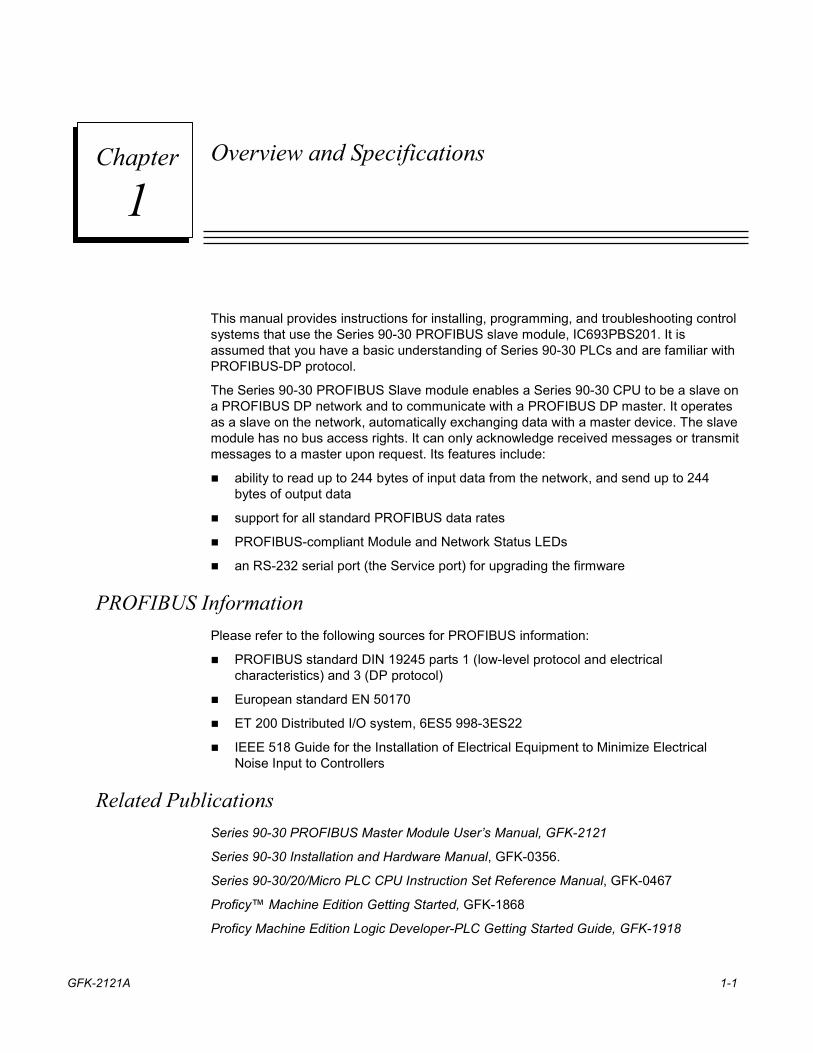
LEDs System (SYS) and Communications (COM) indicators
2
Service Port RS232, 9-pin male, D-Shell Connector. Used for module firmware upgrades.
3
PROFIBUS Port
9-pin female D-Shell Connector. Used for connecting to a PROFIBUS network.
4
Label (not shown)
Label on side of module contains catalog number, description, standard conformance, and serial number information
Figure 1-1. PROFIBUS Slave Module
IC693PBS201 Slave Module Specifications Catalog number IC693PBS201 Description Series 90-30 Slave module for PROFIBUS DP networks Configuration software requirement
Requires Proficy Machine Edition Logic Developer version 2.6 or later
CPU version requirement
Requires CPU firmware version 8.00 or later
Mounting location Can reside in any Series 90-30 baseplate (CPU, expansion, or remote) slot except for slot 1 of a modular CPU baseplate
Environment Storage temperature = –40°C to 85°C Operating temperature = 0°C to 60°C
Backplane current consumption
450 mA at 5VDC (typical)
Data rates Supports all standard Data Rates (9.6KBps, 19.2KBps, 93.75KBps, 187.5KBps, 500KBps, 1.5Mbps, 3MBps, 6MBps and 12MBps)
Status information Slave Status Word Firmware module revision
Note: The PROFIBUS Slave module does not support Sync and Freeze modes
GFK-2121A Chapter 1 Overview and Specifications 1-3
1
PROFIBUS Basics
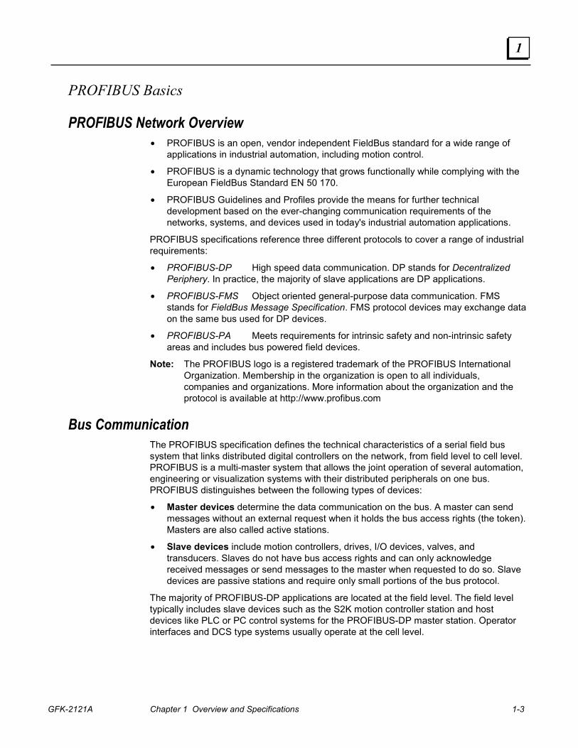
PROFIBUS Network Overview • PROFIBUS is an open, vendor independent FieldBus standard for a wide range of
applications in industrial automation, including motion control.
• PROFIBUS is a dynamic technology that grows functionally while complying with the European FieldBus Standard EN 50 170.
• PROFIBUS Guidelines and Profiles provide the means for further technical development based on the ever-changing communication requirements of the networks, systems, and devices used in today's industrial automation applications.
PROFIBUS specifications reference three different protocols to cover a range of industrial requirements:
• PROFIBUS-DP High speed data communication. DP stands for Decentralized Periphery. In practice, the majority of slave applications are DP applications.
• PROFIBUS-FMS Object oriented general-purpose data communication. FMS stands for FieldBus Message Specification. FMS protocol devices may exchange data on the same bus used for DP devices.
• PROFIBUS-PA Meets requirements for intrinsic safety and non-intrinsic safety areas and includes bus powered field devices.
Note: The PROFIBUS logo is a registered trademark of the PROFIBUS International Organization. Membership in the organization is open to all individuals, companies and organizations. More information about the organization and the protocol is available at http://www.profibus.com
Bus Communication The PROFIBUS specification defines the technical characteristics of a serial field bus system that links distributed digital controllers on the network, from field level to cell level. PROFIBUS is a multi-master system that allows the joint operation of several automation, engineering or visualization systems with their distributed peripherals on one bus. PROFIBUS distinguishes between the following types of devices:
• Master devices determine the data communication on the bus. A master can send messages without an external request when it holds the bus access rights (the token). Masters are also called active stations.
• Slave devices include motion controllers, drives, I/O devices, valves, and transducers. Slaves do not have bus access rights and can only acknowledge received messages or send messages to the master when requested to do so. Slave devices are passive stations and require only small portions of the bus protocol.
The majority of PROFIBUS-DP applications are located at the field level. The field level typically includes slave devices such as the S2K motion controller station and host devices like PLC or PC control systems for the PROFIBUS-DP master station. Operator interfaces and DCS type systems usually operate at the cell level.
1-4 Series 90™-30 PROFIBUS Slave Module User's Manual – August 2004 GFK-2121A
1
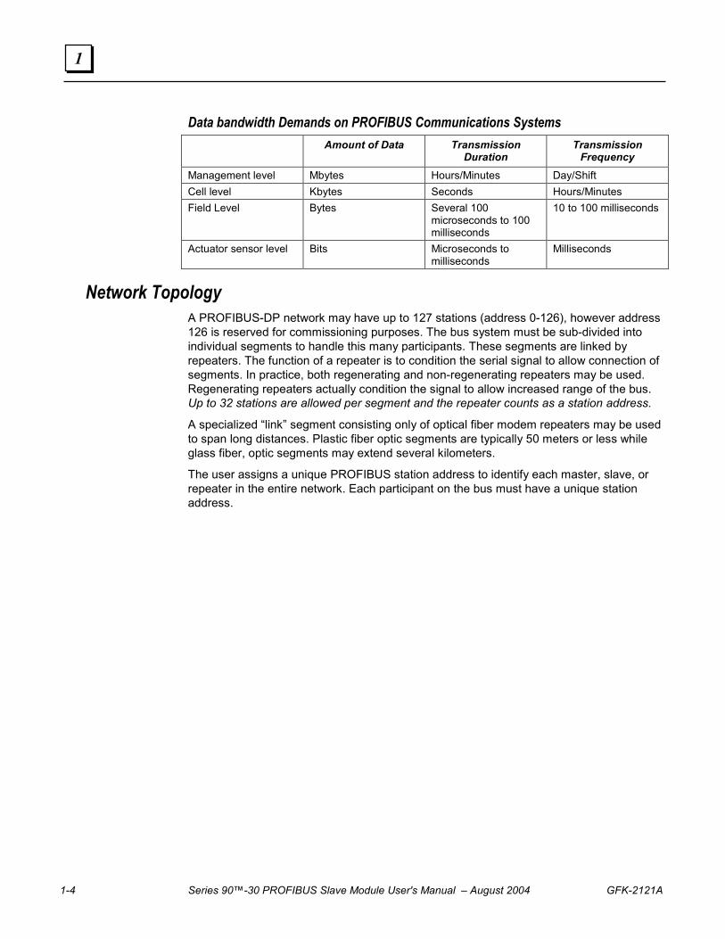
Data bandwidth Demands on PROFIBUS Communications Systems Amount of Data Transmission
Duration Transmission
Frequency Management level Mbytes Hours/Minutes Day/Shift Cell level Kbytes Seconds Hours/Minutes Field Level Bytes Several 100
microseconds to 100 milliseconds
10 to 100 milliseconds
Actuator sensor level Bits Microseconds to milliseconds
Milliseconds
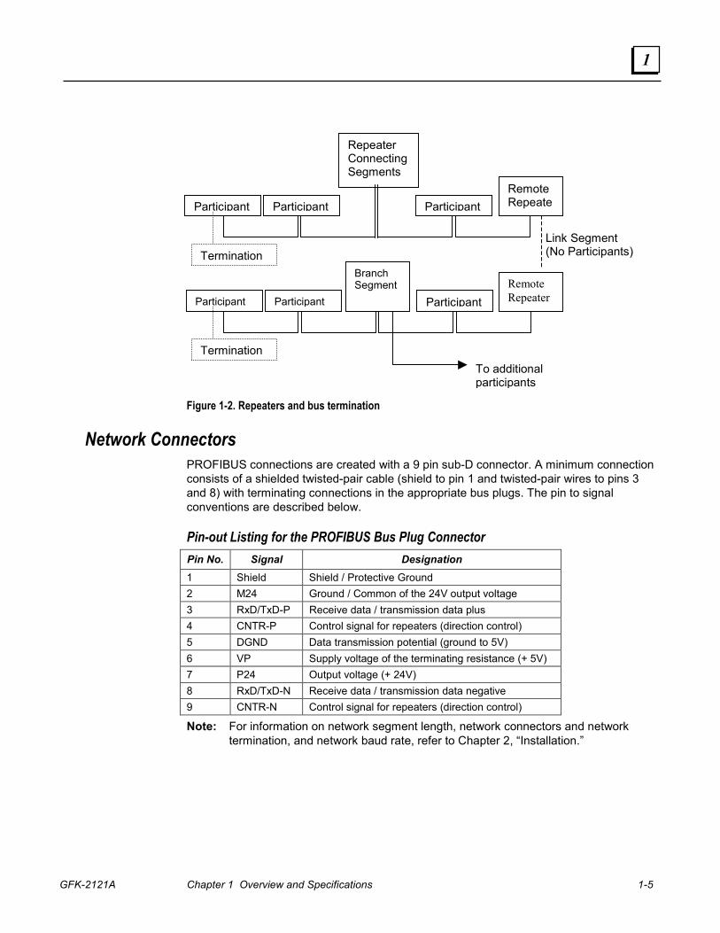
Network Topology A PROFIBUS-DP network may have up to 127 stations (address 0-126), however address 126 is reserved for commissioning purposes. The bus system must be sub-divided into individual segments to handle this many participants. These segments are linked by repeaters. The function of a repeater is to condition the serial signal to allow connection of segments. In practice, both regenerating and non-regenerating repeaters may be used. Regenerating repeaters actually condition the signal to allow increased range of the bus. Up to 32 stations are allowed per segment and the repeater counts as a station address.
A specialized “link” segment consisting only of optical fiber modem repeaters may be used to span long distances. Plastic fiber optic segments are typically 50 meters or less while glass fiber, optic segments may extend several kilometers.
The user assigns a unique PROFIBUS station address to identify each master, slave, or repeater in the entire network. Each participant on the bus must have a unique station address.
GFK-2121A Chapter 1 Overview and Specifications 1-5
1
Figure 1-2. Repeaters and bus termination
Network Connectors PROFIBUS connections are created with a 9 pin sub-D connector. A minimum connection consists of a shielded twisted-pair cable (shield to pin 1 and twisted-pair wires to pins 3 and 8) with terminating connections in the appropriate bus plugs. The pin to signal conventions are described below.
Pin-out Listing for the PROFIBUS Bus Plug Connector Pin No. Signal Designation 1 Shield Shield / Protective Ground 2 M24 Ground / Common of the 24V output voltage 3 RxD/TxD-P Receive data / transmission data plus 4 CNTR-P Control signal for repeaters (direction control) 5 DGND Data transmission potential (ground to 5V) 6 VP Supply voltage of the terminating resistance (+ 5V) 7 P24 Output voltage (+ 24V) 8 RxD/TxD-N Receive data / transmission data negative 9 CNTR-N Control signal for repeaters (direction control)
Note: For information on network segment length, network connectors and network termination, and network baud rate, refer to Chapter 2, “Installation.”
To additional participants
Link Segment (No Participants)
Participant Participant
ParticipantParticipant
Participant
Participant
Branch Segment
Repeater ConnectingSegments
Remote Repeate
Remote Repeater
Termination
Termination
GFK-2193A 2-1
Installation
This chapter contains information on the following procedures:
� Reviewing system power requirements
� Installing the PROFIBUS module in the PLC rack
� Installing PROFIBUS wiring
� Connecting the Slave to the PROFIBUS network
� Selecting the proper line type
� PROFIBUS cable types
� Installing bus termination
Reviewing System Power Requirements Review the power requirements of your system to ensure that your power supply has sufficient capacity to support the PROFIBUS Slave module. Power supply load is automatically calculated by the CIMPLICITY Machine Edition configuration software. Details on manually calculating power supply load can be found in the Series 90-30 Installation and Hardware Manual, GFK-0356.
Note: High capacity Series 90-30 power supplies IC693PWR330 or IC693PWR331 are recommended, particularly for systems with CPU350 or higher, or that have Ethernet adapters and/or multiple PROFIBUS modules. The Series 90-30 PROFIBUS Slave module consumes 450mA at 5VDC (typical).
Installing the PROFIBUS Module in the PLC Rack 1. Remove power from Series 90-30 rack.
2. Turn off power to rack.
3. Place the module into slot 1 or higher in the rack (slot 2 or higher in the Main rack) by hooking the top of the module on the notch above the slot and slowly lowering the module until it snaps into place.
4. Attach the PROFIBUS cable and terminate as required.
Note: For details about installing Series 90-30 rack systems and modules, refer to the Series 90-30 Installation Manual and Hardware Manual, GFK-0356.
2 Chapter

2-2 Series 90™-30 PROFIBUS Slave Module User's Manual – August 2004 GFK-2193A
2
Connecting the Slave to the PROFIBUS Network
Network Segment Length A PROFIBUS network uses either fiber optic or RS-485 copper media. The copper bus line specified in EN 50 170 is “Line Type A” and is the recommended cable type. A more economical copper cable “Line Type B” is commonly used for smaller installations; however, it is not specified in EN 50 170. It is extremely important to use cable rated to PROFIBUS specifications. The higher the baud rate selected and the longer the distances involved, the more critical cable selection becomes. (PROFIBUS cable has a distinctive purple color.)
Stub or “T” type branch connections are supported if the total stub (branch) lengths do not exceed 6.6 meters. Do not use stubs at all on 12 Mbaud networks.
The data rates for network communication with maximum segment trunk length per cable type are provided below. Multiple segments may be connected via repeater stations to extend the total bus length.
Line Types Baud Rate Line A
Distance (Max) 1, 2 Line B
Distance (Max) 1, 2 Glass Fiber
9.6KBps, 19.2KBps and 93.75KBps 1200 m 1200 m 6Km 187.5KBps 1000 m 600 m 6Km 500KBps 400 m 200 m 6Km 1.5MBps 200 m NA 6Km 3, 6 and 12MBps 100 m NA 6Km
1 If using a combination of both line types, divide the lengths shown by two. 2 Values shown are the sum of all bus segment and drop cable lengths. NA = Not Applicable Note: The two physical ends of the PROFIBUS network should be terminated. There
should be two, and only two, terminators on a network.
GFK-2193A Chapter 2 Installation 2-3
2
PROFIBUS Cable Types The recommended cable is
� Belden 3079A PROFIBUS Cable
This is a shielded, 150 ohm twinaxial (single twisted pair) cable. It has 22 AWG conductors and a mutual capacitance of 9.0 pF per foot, nominal. For complete specifications on this cable, please contact your Belden dealer or visit their website at www.belden.com.
Alternate cable types are:
� Siemens 6XV1 830-OAH10 Two Core shielded
� Siemens 6XV1 830-OBH10 w/PE Sheath
� Siemens 6XV1 830-3AH10 for underground burial
� Siemens 6XV1 830-3BH10 trailing cable
� Bosch Comnet DP #913 548 Flexible PROFIBUS cable
� Bosch Comnet DP #917 201 Trailing PROFIBUS Cable
� Bosch Comnet DP #917 202 Massive PROFIBUS Cable
Note: Allen Bradley “blue hose,” which has an impedance of 78 ohms, is not recommended for this application.
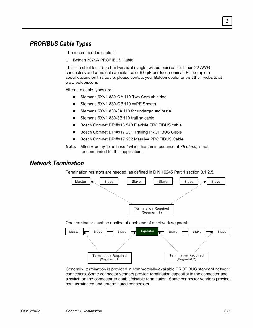
Network Termination Termination resistors are needed, as defined in DIN 19245 Part 1 section 3.1.2.5.
Master Slave Slave Slave SlaveSlave
Termination Required(Segment 1)
One terminator must be applied at each end of a network segment.
Master Slave Slave Slave SlaveSlaveRepeater
Termination Required(Segment 1)
Term ination Required(Segment 2)
Generally, termination is provided in commercially-available PROFIBUS standard network connectors. Some connector vendors provide termination capability in the connector and a switch on the connector to enable/disable termination. Some connector vendors provide both terminated and unterminated connectors.
2-4 Series 90™-30 PROFIBUS Slave Module User's Manual – August 2004 GFK-2193A
2
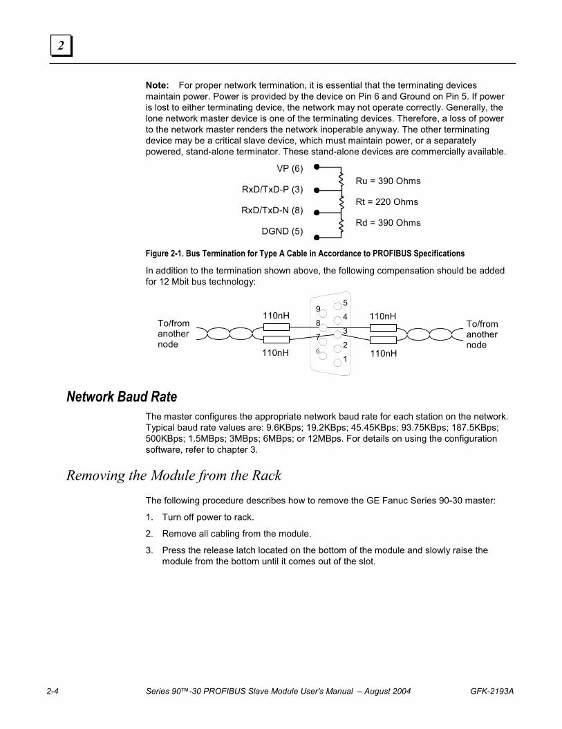
Note: For proper network termination, it is essential that the terminating devices maintain power. Power is provided by the device on Pin 6 and Ground on Pin 5. If power is lost to either terminating device, the network may not operate correctly. Generally, the lone network master device is one of the terminating devices. Therefore, a loss of power to the network master renders the network inoperable anyway. The other terminating device may be a critical slave device, which must maintain power, or a separately powered, stand-alone terminator. These stand-alone devices are commercially available.
VP (6)
RxD/TxD-P (3)
RxD/TxD-N (8)
DGND (5)
Ru = 390 Ohms
Rt = 220 Ohms
Rd = 390 Ohms
Figure 2-1. Bus Termination for Type A Cable in Accordance to PROFIBUS Specifications
In addition to the termination shown above, the following compensation should be added for 12 Mbit bus technology:
To/fromanothernode
110nH
110nHTo/fromanothernode
110nH
110nH5
4
3
2
1
9
8
76
Network Baud Rate The master configures the appropriate network baud rate for each station on the network. Typical baud rate values are: 9.6KBps; 19.2KBps; 45.45KBps; 93.75KBps; 187.5KBps; 500KBps; 1.5MBps; 3MBps; 6MBps; or 12MBps. For details on using the configuration software, refer to chapter 3.
Removing the Module from the Rack The following procedure describes how to remove the GE Fanuc Series 90-30 master:
1. Turn off power to rack.
2. Remove all cabling from the module.
3. Press the release latch located on the bottom of the module and slowly raise the module from the bottom until it comes out of the slot.
GFK-2193A 3-1
Configuration
These configuration procedures are intended for users with at least a basic knowledge of the CIMPLICITY Machine Edition Logic Developer software and the Series 90-30 PLC. For help with using the software, please see the software’s built-in help system.
Note: The PROFIBUS Slave is supported only in Machine Edition Logic Developer-PLC.
Adding a PROFIBUS Slave Module to the Hardware Configuration Add the IC693PBS201 module to the PLC rack configuration.
1. In the Project tab of the Navigator, expand the Hardware Configuration folder.
2. In the Hardware Configuration folder, right click the PLC Slot where you wish to install the PROFIBUS Slave module. Note that a PROFIBUS module is not a valid choice for slot 1 of a modular CPU rack.
3. Select Add Module from the shortcut menu. The Module Catalog dialog box appears.
Note: To edit a module that already appears in the rack, right click the module and select Configure. The module’s Parameter Editor window opens.
4. Click the Communications tab. The Communications module list appears.
5. Select the IC693PBS201 PROFIBUS Slave and click the OK button. The module is added to the PLC configuration in the Navigator window, and the module’s Parameter Editor window appears in the InfoViewer window space.
3 Chapter
3-2 Series 90™-30 PROFIBUS Slave Module User's Manual – August 2004 GFK-2193A
3
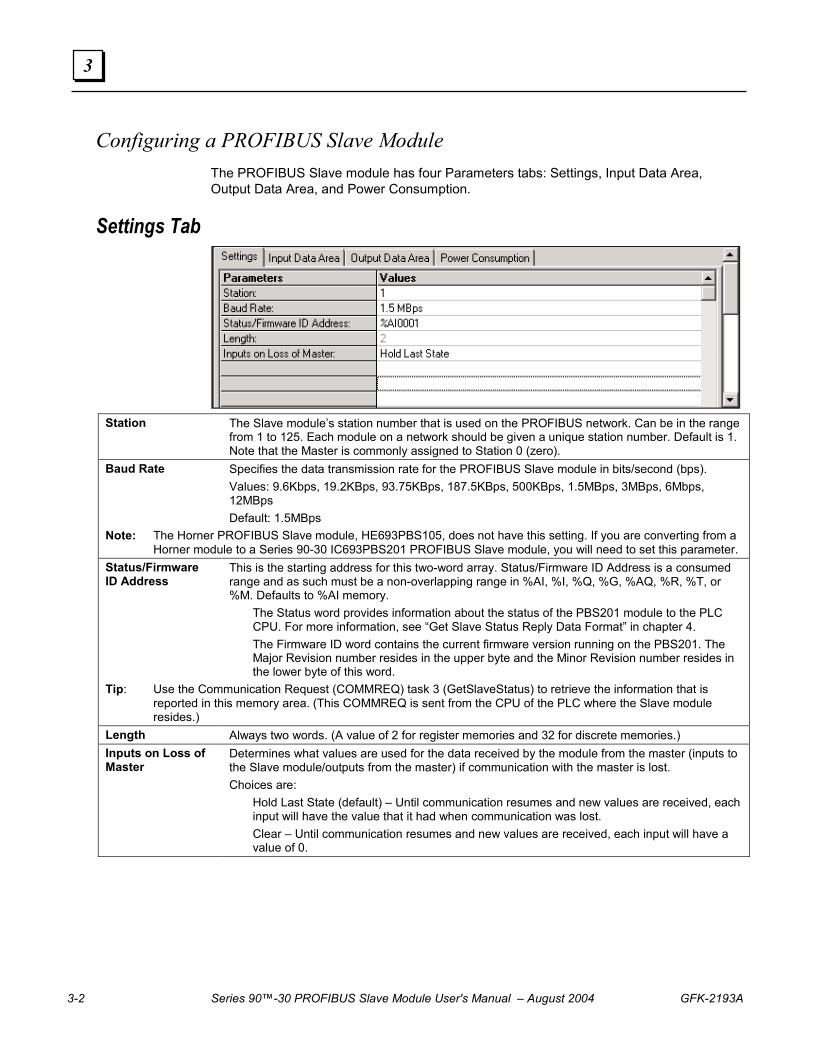
Configuring a PROFIBUS Slave Module The PROFIBUS Slave module has four Parameters tabs: Settings, Input Data Area, Output Data Area, and Power Consumption.
Settings Tab
Station The Slave module’s station number that is used on the PROFIBUS network. Can be in the range
from 1 to 125. Each module on a network should be given a unique station number. Default is 1. Note that the Master is commonly assigned to Station 0 (zero).
Baud Rate Specifies the data transmission rate for the PROFIBUS Slave module in bits/second (bps). Values: 9.6Kbps, 19.2KBps, 93.75KBps, 187.5KBps, 500KBps, 1.5MBps, 3MBps, 6Mbps, 12MBps Default: 1.5MBps
Note: The Horner PROFIBUS Slave module, HE693PBS105, does not have this setting. If you are converting from a Horner module to a Series 90-30 IC693PBS201 PROFIBUS Slave module, you will need to set this parameter.
Status/Firmware ID Address
This is the starting address for this two-word array. Status/Firmware ID Address is a consumed range and as such must be a non-overlapping range in %AI, %I, %Q, %G, %AQ, %R, %T, or %M. Defaults to %AI memory. The Status word provides information about the status of the PBS201 module to the PLC
CPU. For more information, see “Get Slave Status Reply Data Format” in chapter 4. The Firmware ID word contains the current firmware version running on the PBS201. The
Major Revision number resides in the upper byte and the Minor Revision number resides in the lower byte of this word.
Tip: Use the Communication Request (COMMREQ) task 3 (GetSlaveStatus) to retrieve the information that is reported in this memory area. (This COMMREQ is sent from the CPU of the PLC where the Slave module resides.)
Length Always two words. (A value of 2 for register memories and 32 for discrete memories.) Inputs on Loss of Master
Determines what values are used for the data received by the module from the master (inputs to the Slave module/outputs from the master) if communication with the master is lost. Choices are: Hold Last State (default) – Until communication resumes and new values are received, each
input will have the value that it had when communication was lost. Clear – Until communication resumes and new values are received, each input will have a
value of 0.
GFK-2193A Chapter 3 Configuration 3-3
3
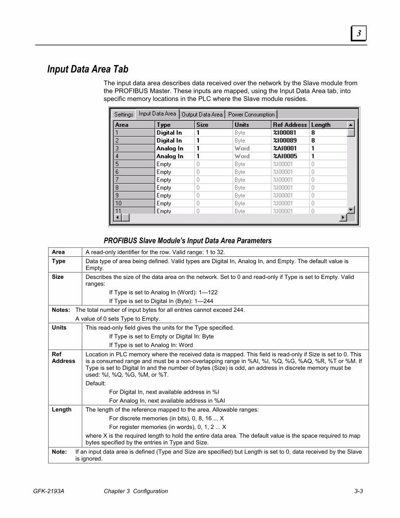
Input Data Area Tab The input data area describes data received over the network by the Slave module from the PROFIBUS Master. These inputs are mapped, using the Input Data Area tab, into specific memory locations in the PLC where the Slave module resides.
PROFIBUS Slave Module’s Input Data Area Parameters Area A read-only identifier for the row. Valid range: 1 to 32. Type Data type of area being defined. Valid types are Digital In, Analog In, and Empty. The default value is
Empty. Size Describes the size of the data area on the network. Set to 0 and read-only if Type is set to Empty. Valid
ranges: If Type is set to Analog In (Word): 1—122 If Type is set to Digital In (Byte): 1—244
Notes: The total number of input bytes for all entries cannot exceed 244. A value of 0 sets Type to Empty. Units This read-only field gives the units for the Type specified.
If Type is set to Empty or Digital In: Byte If Type is set to Analog In: Word
Ref Address
Location in PLC memory where the received data is mapped. This field is read-only if Size is set to 0. This is a consumed range and must be a non-overlapping range in %AI, %I, %Q, %G, %AQ, %R, %T or %M. If Type is set to Digital In and the number of bytes (Size) is odd, an address in discrete memory must be used: %I, %Q, %G, %M, or %T. Default: For Digital In, next available address in %I For Analog In, next available address in %AI
Length The length of the reference mapped to the area. Allowable ranges: For discrete memories (in bits), 0, 8, 16 ... X For register memories (in words), 0, 1, 2 ... X where X is the required length to hold the entire data area. The default value is the space required to map bytes specified by the entries in Type and Size.
Note: If an input data area is defined (Type and Size are specified) but Length is set to 0, data received by the Slave is ignored.
3-4 Series 90™-30 PROFIBUS Slave Module User's Manual – August 2004 GFK-2193A
3
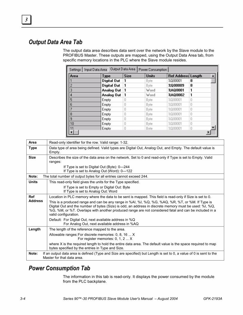
Output Data Area Tab The output data area describes data sent over the network by the Slave module to the PROFIBUS Master. These outputs are mapped, using the Output Data Area tab, from specific memory locations in the PLC where the Slave module resides.
Area Read-only identifier for the row. Valid range: 1-32. Type Data type of area being defined. Valid types are Digital Out, Analog Out, and Empty. The default value is
Empty. Size Describes the size of the data area on the network. Set to 0 and read-only if Type is set to Empty. Valid
ranges: If Type is set to Digital Out (Byte): 0—244 If Type is set to Analog Out (Word): 0—122
Note: The total number of output bytes for all entries cannot exceed 244. Units This read-only field gives the units for the Type specified.
If Type is set to Empty or Digital Out: Byte If Type is set to Analog Out: Word
Ref Address
Location in PLC memory where the data to be sent is mapped. This field is read-only if Size is set to 0. This is a produced range and can be any range in %AI, %I, %Q, %G, %AQ, %R, %T, or %M. If Type is Digital Out and the number of bytes (Size) is odd, an address in discrete memory must be used: %I, %Q, %G, %M, or %T. Overlaps with another produced range are not considered fatal and can be included in a valid configuration. Default: For Digital Out, next available address in %Q For Analog Out, next available address in %AQ
Length The length of the reference mapped to the area. Allowable ranges: For discrete memories: 0, 8, 16 ... X For register memories: 0, 1, 2 ... X where X is the required length to hold the entire data area. The default value is the space required to map bytes specified by the entries in Type and Size.
Note: If an output data area is defined (Type and Size are specified) but Length is set to 0, a value of 0 is sent to the Master for that data area.
Power Consumption Tab The information in this tab is read-only. It displays the power consumed by the module from the PLC backplane.
GFK-2193A 4-1
Status and Diagnostics
The following methods can be used to obtain status and diagnostic data:
� Observing and interpreting the LED indicators on the PROFIBUS module, described below
� Monitoring the Status/Firmware ID Array, page 4-2
� Using Communications Request (COMMREQ) ladder logic instructions to instruct the PROFIBUS module to gather diagnostic or status data and report it to the PLC CPU, page 4-3
Note: The PROFIBUS Slave Module does not generate faults for the Fault Table.
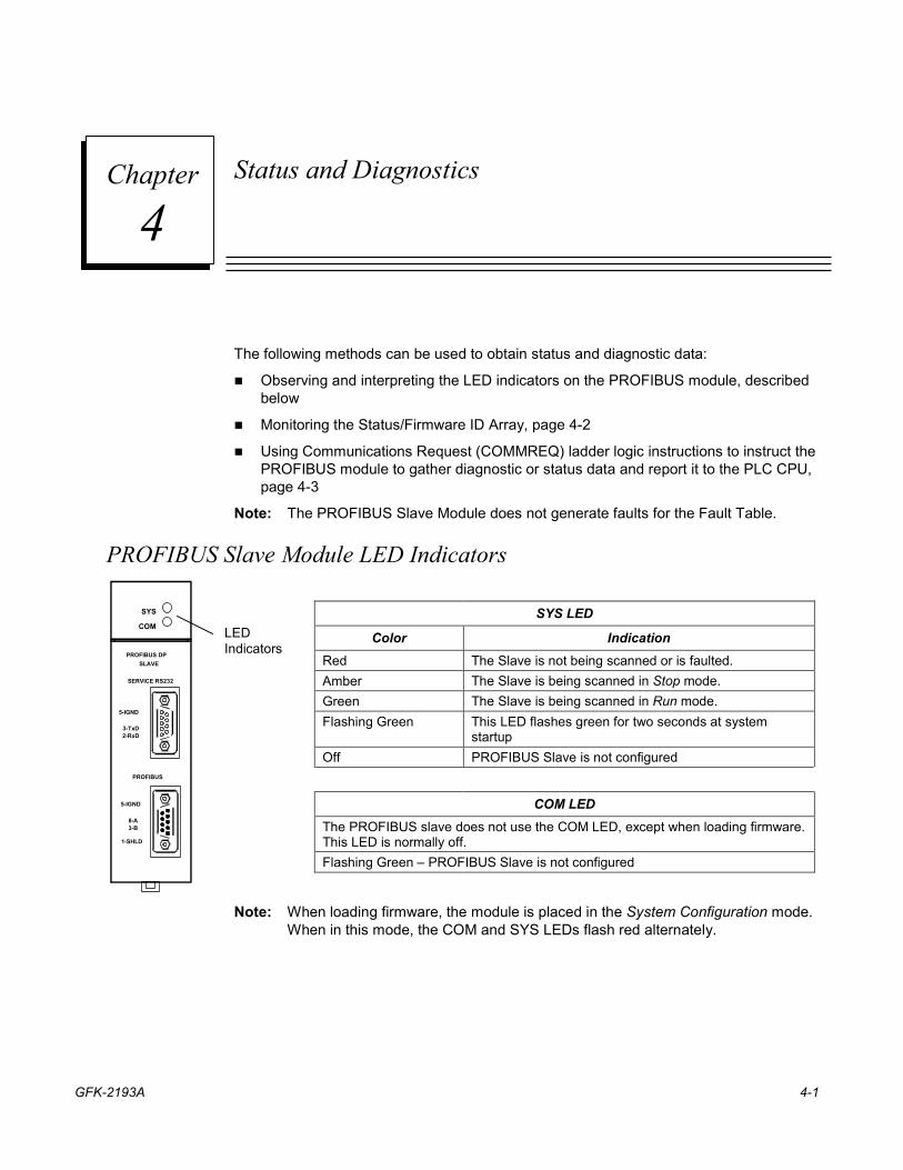
PROFIBUS Slave Module LED Indicators
SYS LED
Color Indication Red The Slave is not being scanned or is faulted. Amber The Slave is being scanned in Stop mode. Green The Slave is being scanned in Run mode. Flashing Green This LED flashes green for two seconds at system
startup Off PROFIBUS Slave is not configured
COM LED The PROFIBUS slave does not use the COM LED, except when loading firmware. This LED is normally off. Flashing Green – PROFIBUS Slave is not configured
SYS
COM
PROFIBUS DPSLAVE
5-IGND
SERVICE RS232
PROFIBUS
3-TxD2-RxD
5-IGND
8-A3-B
1-SHLD
LEDIndicators
Note: When loading firmware, the module is placed in the System Configuration mode. When in this mode, the COM and SYS LEDs flash red alternately.
4 Chapter
4-2 Series 90™-30 PROFIBUS Slave Module User's Manual – August 2004 GFK-2193A
4
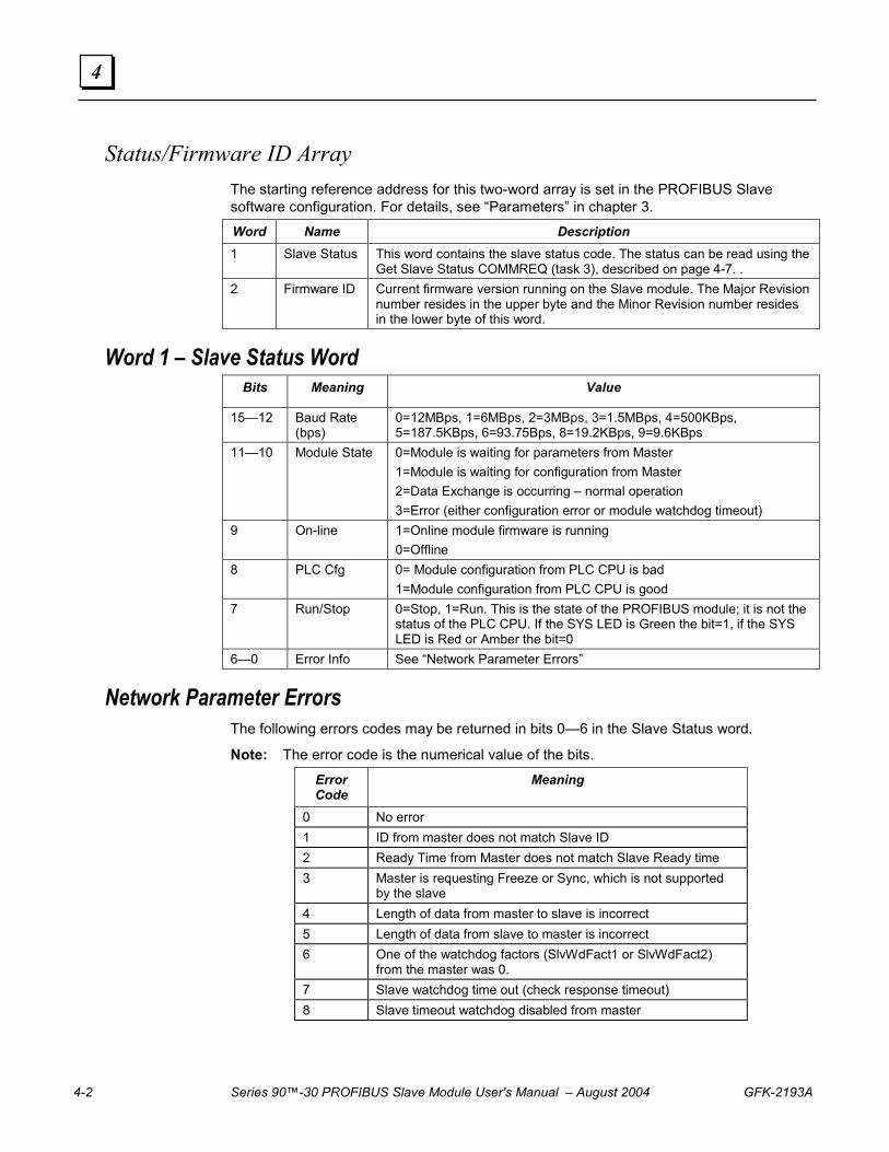
Status/Firmware ID Array The starting reference address for this two-word array is set in the PROFIBUS Slave software configuration. For details, see “Parameters” in chapter 3.
Word Name Description 1 Slave Status This word contains the slave status code. The status can be read using the
Get Slave Status COMMREQ (task 3), described on page 4-7. . 2 Firmware ID Current firmware version running on the Slave module. The Major Revision
number resides in the upper byte and the Minor Revision number resides in the lower byte of this word.
Word 1 – Slave Status Word Bits Meaning Value
15—12 Baud Rate (bps)
0=12MBps, 1=6MBps, 2=3MBps, 3=1.5MBps, 4=500KBps, 5=187.5KBps, 6=93.75Bps, 8=19.2KBps, 9=9.6KBps
11—10 Module State 0=Module is waiting for parameters from Master 1=Module is waiting for configuration from Master 2=Data Exchange is occurring – normal operation 3=Error (either configuration error or module watchdog timeout)
9 On-line 1=Online module firmware is running 0=Offline
8 PLC Cfg 0= Module configuration from PLC CPU is bad 1=Module configuration from PLC CPU is good
7 Run/Stop 0=Stop, 1=Run. This is the state of the PROFIBUS module; it is not the status of the PLC CPU. If the SYS LED is Green the bit=1, if the SYS LED is Red or Amber the bit=0
6—0 Error Info See “Network Parameter Errors”
Network Parameter Errors The following errors codes may be returned in bits 0—6 in the Slave Status word.
Note: The error code is the numerical value of the bits.
Error Code
Meaning
0 No error 1 ID from master does not match Slave ID 2 Ready Time from Master does not match Slave Ready time 3 Master is requesting Freeze or Sync, which is not supported
by the slave 4 Length of data from master to slave is incorrect 5 Length of data from slave to master is incorrect 6 One of the watchdog factors (SlvWdFact1 or SlvWdFact2)
from the master was 0. 7 Slave watchdog time out (check response timeout) 8 Slave timeout watchdog disabled from master
GFK-2193A Chapter 4 Status and Diagnostics 4-3
4
Enable Input
Command Block Pointer
Rack/Slot Location
Task #
Fault Output
COMM_REQ
IN FT
SYSID
TASK
Communication Requests
The Communications Request uses the parameters of the COMMREQ Ladder Instruction and an associated Command Block to define the characteristics of the request. An associated Status Word reports the results of each request.
The Communication Request function (COMMREQ) allows the program to communicate with a GE Fanuc intelligent module, such as a PROFIBUS slave module.
The COMMREQ function uses a command block that contains the data to be communicated to the other device, plus information related to the execution of the COMMREQ. The command block must be placed in the designated memory area using data move instructions, such as MOVE or BLKMOV (Block Move).
The CPU reports the result of the COMMREQ in the status word, which is a single location in PLC data memory. The status word address is specified in the command block. For a list of status codes reported in the status word, see “COMMREQ Status Word” on page 4-6.
The PROFIBUS slave module supports one COMMREQ, described on page 4-7.
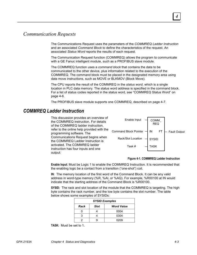
COMMREQ Ladder Instruction This discussion provides an overview of the COMMREQ instruction. For details of the COMMREQ ladder instruction, refer to the online help provided with the programming software. The Communications Request begins when the COMMREQ Ladder Instruction is activated. The COMMREQ ladder instruction has four inputs and one output:
Figure 4-1. COMMREQ Ladder Instruction
Enable Input: Must be Logic 1 to enable the COMMREQ Instruction. It is recommended that the enabling logic be a contact from a transition (“one-shot”) coil.
IN: The memory location of the first word of the Command Block. It can be any valid address in word-type memory (%R, %AI, or %AQ). For example, %R00100 at IN would indicate that the starting address of the Command Block is %R00100.
SYSID: The rack and slot location of the module that the COMMREQ is targeting. The high byte contains the rack number, and the low byte contains the slot number. The table below shows some examples of SYSIDs:
SYSID Examples
Rack Slot Word Value 0 4 0004 3 4 0304 2 9 0209
TASK: Must be set to 1.

4-4 Series 90™-30 PROFIBUS Slave Module User's Manual – August 2004 GFK-2193A
4
FT Output: The function’s FT (fault) output can provide an output to optional logic that can verify successful completion of the Communications Request. The FT output can have these states:
FT Output Truth Table
Enable Input Status Does an Error Exist? FT output
Active No Low Active Yes High Not active No execution Low
� The FT output is set High if:
� The specified target address is not present (for example, specifying Rack 1 when the system only uses Rack 0).
� The specified task number is not valid for the device.
� Data length is set to 0.
� The FT output can either be connected to another device, such as a set coil, or can be left open.
Operation of the Communications Request The figure below illustrates the flow of information between the PLC CPU and the PROFIBUS Slave module:
Status bits
Requested data
Command
PLC CPU
Ladderprogram
• COMMREQ
CPUmemory
• Data• Status word
PROFIBUS SlaveModule
Firmwareinstructions
On-boardmemory
PLCBackplane
PROFIBUSnetwork
to Master
Figure 4-2. Operation of the PROFIBUS Communications Request
A Communications Request is initiated when a COMMREQ ladder instruction is activated during the PLC scan. At this time, a command from the PLC via the Communications Request is sent to the PROFIBUS Master module (PBM).
At the conclusion of every request, the PLC CPU reports the status of the request to the Status Word, which is a location in PLC memory that is designated by the Status Word Pointer in the Command Block.
In Figure 4-2, the PBM is shown in the CPU rack and communications occur over the PLC backplane. If the PBM is located in an expansion or remote rack, the commands and data are sent over the CPU rack’s backplane, through the expansion or remote cable to the rack containing the PBM, and across that rack’s backplane to the PBM.
GFK-2193A Chapter 4 Status and Diagnostics 4-5
4
COMMREQ Programming Requirements and Recommendations � COMMREQ instructions should be enabled by a contact from a transition coil.
� If using more than one COMMREQ in a ladder program, verify that a previous COMMREQ executed successfully before executing another one. This can be done by checking the Status Word and the FT (Fault) output.
� The FT output is held False if the Enable Input is not active. This means that if the COMMREQ is enabled by a transitional (one-shot) contact and a fault occurs, the FT output is High for only one PLC scan. To capture the fact that a fault occurred, you can program the fault output as a Set coil, which would not be automatically reset at the end of a scan. Additional logic would then be needed to reset the fault output coil after the fault is acknowledged and before the next execution of the COMMREQ.
� Programming a device, such as a Set Coil, on the FT output of the COMMREQ is optional; this output may be left open if desired.
� It is necessary to initialize the data in the Command Block before executing the COMMREQ instruction. Since the normal PLC sweep order is from top to bottom, initializing the Command Block in an earlier rung (or rungs) than the rung that contains the COMMREQ will satisfy this requirement.
Error Detection and Handling As shown in “COMMREQ Status Word”, a value of 1 is returned to the Status Word if communications proceed normally, but if any error condition is detected, a value greater than 1 is returned. If you require error detection in your ladder program, you can use a Greater Than (GT) compare instruction to determine if the value in the Status Word is negative (less than zero). If an error occurs, the GT instruction’s output (Q) will go high. A coil driven by the output can be used to enable fault handling or error reporting logic.
The FT output of the COMMREQ, described on page 4-4, goes high for certain faults and can be used for fault detection also. Additionally, the first Status Word can be monitored by error message logic for display on an Operator Interface device, in which case, Status Word codes would correspond to appropriate error messages that would display on the operator screen.
To dynamically check the Status Word, write a non-significant positive number (0 or 99 are typically used) into the Status Word each time before its associated COMMREQ is executed. If the instruction executes successfully, the CPU will write the number 1 there. This method lets you know that if the number 1 is present, the last COMMREQ executed successfully, and that the 1 was not just left over from a previous execution.
When multiple COMMREQs are used, it is recommended that each be verified for successful communications before the next is enabled. Monitoring the Status Word is one way to accomplish this.
Corrective Actions for COMMREQ Errors The type of corrective action to take depends upon the application. If an error occurs during the startup or debugging stage of ladder development, you should verify the COMMREQ parameters. The same is true if an error occurs right after a program is modified. But, if an error occurs in a proven application that has been running successfully, the problem is more likely to be hardware-related. The PLC fault tables should be checked for possible additional information when troubleshooting Status Word errors.
4-6 Series 90™-30 PROFIBUS Slave Module User's Manual – August 2004 GFK-2193A
4
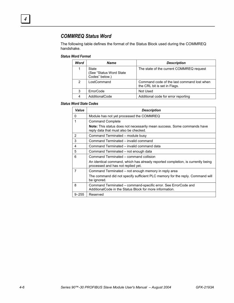
COMMREQ Status Word The following table defines the format of the Status Block used during the COMMREQ handshake.
Status Word Format Word Name Description
1 State (See “Status Word State Codes” below.)
The state of the current COMMREQ request
2 LostCommand Command code of the last command lost when the CRL bit is set in Flags.
3 ErrorCode Not Used 4 AdditionalCode Additional code for error reporting
Status Word State Codes Value Description 0 Module has not yet processed the COMMREQ 1 Command Complete
Note: This status does not necessarily mean success. Some commands have reply data that must also be checked.
2 Command Terminated – module busy 3 Command Terminated – invalid command 4 Command Terminated – invalid command data 5 Command Terminated – not enough data 6 Command Terminated – command collision
An identical command, which has already reported completion, is currently being processed and has not replied yet.
7 Command Terminated – not enough memory in reply area The command did not specify sufficient PLC memory for the reply. Command will be ignored.
8 Command Terminated – command-specific error. See ErrorCode and AdditionalCode in the Status Block for more information.
9–255 Reserved

GFK-2193A Chapter 4 Status and Diagnostics 4-7
4
PROFIBUS Slave Module COMMREQ Reference The PROFIBUS Slave module supports the following COMMREQ tasks and responses. Task Name Description Page No.3 Get Slave Status Retrieves detailed status information for the Slave. 4-7 5 Read Module Header Retrieves module header information. 4-10 6 Clear Counters Clears counters in ReadModuleHeader 4-12
Get Slave Status COMMREQ (3) The Get Slave Status COMMREQ retrieves detailed status information for the slave module from the 16-bit slave status word. The starting address of this word is configured as Status/Firmware ID Address in the PROFIBUS Slave module software configuration. For details, refer to “Parameters” in chapter 3.
Memory Types The following table lists the memory types that can be used for the Status Block and Reply Data areas.
COMMREQ Status Word Memory Type Codes Memory Type Abbreviation Memory Type Decimal
code to enter %I Discrete input table (BYTE mode) 16 %Q Discrete output table (BYTE mode) 18 %R Register memory 8 %AI Analog input table 10 %AQ Analog output table 12 %T Discrete temporary memory (BYTE) 20 %M Discrete internal memory (BYTE) 22
Get Slave Status Command Block – Basic Example Get Slave status for Device Return the COMMREQ status words to %R10—%R13. Return the Slave status to %R251-%R259.
Word Dec (Hex) Definition Word 1 4 (0004) Length of command Data Block Word 2 0 (0000) Always 0 (no-wait mode request) Word 3 8 (0008) Memory type of COMMREQ status word (%R) Word 4 9 (0009) COMMREQ status word address minus 1 (%R10) Word 5 0 (0000) Reserved Word 6 0 (0000) Reserved Word 7 3 (0003) Get Module Status command code. Word 8 8 (0008) Memory type to write response (%R) Word 9 250 (00FA) Starting Address to write response (response written to %R251) Word 10 5 (0005) Maximum size of response area. Must be 2 words or more, or an error
will be reported in the COMMREQ status and the Get Slave Status request will be ignored.
4-8 Series 90™-30 PROFIBUS Slave Module User's Manual – August 2004 GFK-2193A
4
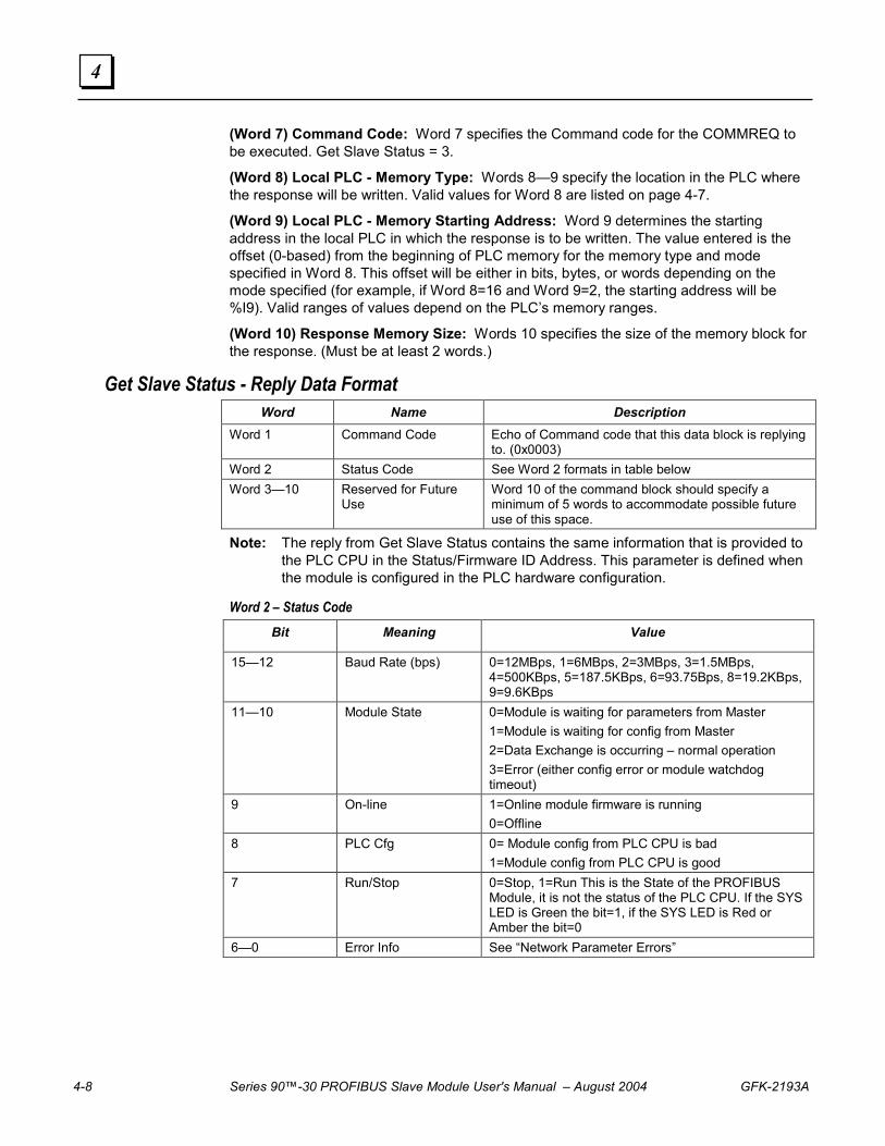
(Word 7) Command Code: Word 7 specifies the Command code for the COMMREQ to be executed. Get Slave Status = 3.
(Word 8) Local PLC - Memory Type: Words 8—9 specify the location in the PLC where the response will be written. Valid values for Word 8 are listed on page 4-7.
(Word 9) Local PLC - Memory Starting Address: Word 9 determines the starting address in the local PLC in which the response is to be written. The value entered is the offset (0-based) from the beginning of PLC memory for the memory type and mode specified in Word 8. This offset will be either in bits, bytes, or words depending on the mode specified (for example, if Word 8=16 and Word 9=2, the starting address will be %I9). Valid ranges of values depend on the PLC’s memory ranges.
(Word 10) Response Memory Size: Words 10 specifies the size of the memory block for the response. (Must be at least 2 words.)
Get Slave Status - Reply Data Format Word Name Description
Word 1 Command Code Echo of Command code that this data block is replying to. (0x0003)
Word 2 Status Code See Word 2 formats in table below Word 3—10 Reserved for Future
Use Word 10 of the command block should specify a minimum of 5 words to accommodate possible future use of this space.
Note: The reply from Get Slave Status contains the same information that is provided to the PLC CPU in the Status/Firmware ID Address. This parameter is defined when the module is configured in the PLC hardware configuration.
Word 2 – Status Code Bit Meaning Value
15—12 Baud Rate (bps) 0=12MBps, 1=6MBps, 2=3MBps, 3=1.5MBps, 4=500KBps, 5=187.5KBps, 6=93.75Bps, 8=19.2KBps, 9=9.6KBps
11—10 Module State 0=Module is waiting for parameters from Master 1=Module is waiting for config from Master 2=Data Exchange is occurring – normal operation 3=Error (either config error or module watchdog timeout)
9 On-line 1=Online module firmware is running 0=Offline
8 PLC Cfg 0= Module config from PLC CPU is bad 1=Module config from PLC CPU is good
7 Run/Stop 0=Stop, 1=Run This is the State of the PROFIBUS Module, it is not the status of the PLC CPU. If the SYS LED is Green the bit=1, if the SYS LED is Red or Amber the bit=0
6—0 Error Info See “Network Parameter Errors”
GFK-2193A Chapter 4 Status and Diagnostics 4-9
4
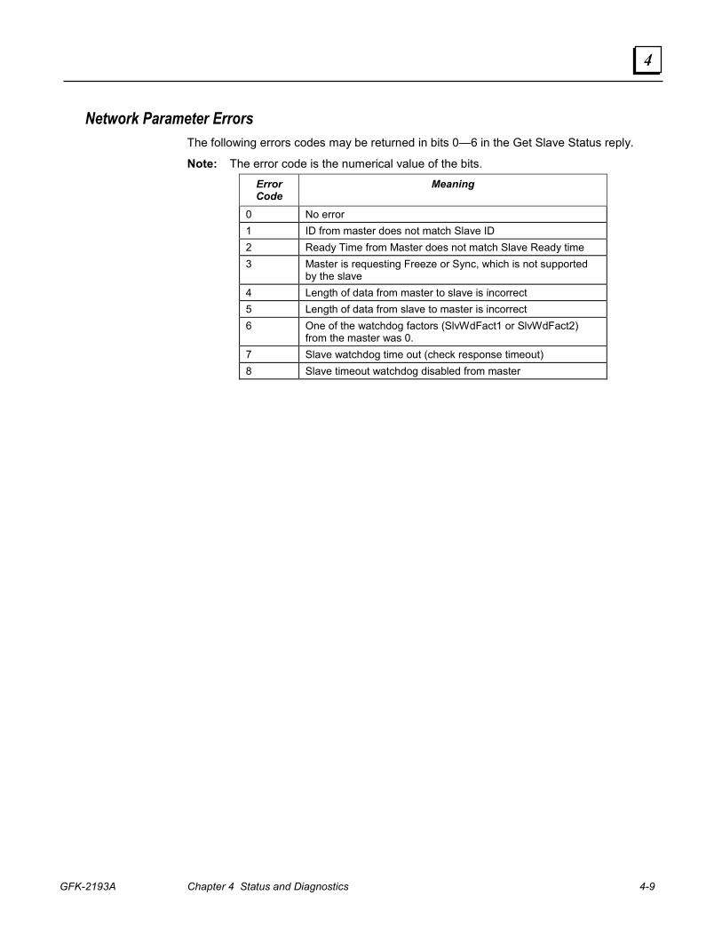
Network Parameter Errors The following errors codes may be returned in bits 0—6 in the Get Slave Status reply.
Note: The error code is the numerical value of the bits.
Error Code
Meaning
0 No error 1 ID from master does not match Slave ID 2 Ready Time from Master does not match Slave Ready time 3 Master is requesting Freeze or Sync, which is not supported
by the slave 4 Length of data from master to slave is incorrect 5 Length of data from slave to master is incorrect 6 One of the watchdog factors (SlvWdFact1 or SlvWdFact2)
from the master was 0. 7 Slave watchdog time out (check response timeout) 8 Slave timeout watchdog disabled from master

4-10 Series 90™-30 PROFIBUS Slave Module User's Manual – August 2004 GFK-2193A
4
Read Module Header (5) The Read Module Header command retrieves Network Diagnostic Information for the Device.
Read Module Header Command Block – Basic Example The following command block accomplishes the following:
Get Module Header Data Return the COMMREQ Status Word to %R10—%R13. Return the Device Status to %R251—%R275.
Word Dec (Hex) Definition Word 1 4 (0004) Length of command Data Block Word 2 0 (0000) Always 0 (no-wait mode request) Word 3 8 (0008) Memory type of COMMREQ status word (%R) Word 4 9 (0009) COMMREQ status word address minus 1 (%R10) Word 5 0 (0000) Reserved Word 6 0 (0000) Reserved Word 7 5 (0005) Read Module Header command number Word 8 8 (0008) Memory type to write response (%R) Word 9 250 (00FA) Starting Address to write response(response written to %R251)Word 10 25 (0019) Size of response area, 25 for slave
(Word 7) Command Code: Word 7 specifies the Command code for the COMMREQ to be executed . Read Module Header = 5
(Word 8) Local PLC - Memory Type: Words 8—9 specify the location in the PLC where the response will be written. Valid values for Word 8 are listed below:
Type
Value Dec (Hex)
Description
%R 8 (0008) Register memory (word mode) %AI 10 (000A) Analog input memory (word mode) %AQ 12 (000C) Analog output memory (word mode) %I 16 (0010) Discrete input memory (byte mode) %Q 18 (0012) Discrete output memory (byte mode) %T 20 (0014) Discrete temporary memory (byte mode) %M 22 (0016) Discrete momentary internal memory (byte mode)
GFK-2193A Chapter 4 Status and Diagnostics 4-11
4
(Word 9) Local PLC - Memory Starting Address: Word 9 determines the starting address in the local PLC in which the response is to be written. The value entered is the offset (0-based) from the beginning of PLC memory for the memory type and mode specified in Word 8. This offset will be either in bits, bytes, or words depending on the mode specified (for example, if Word 8=16 and Word 9=2, the starting address will be %I9). Valid ranges of values depend on the PLC’s memory ranges.
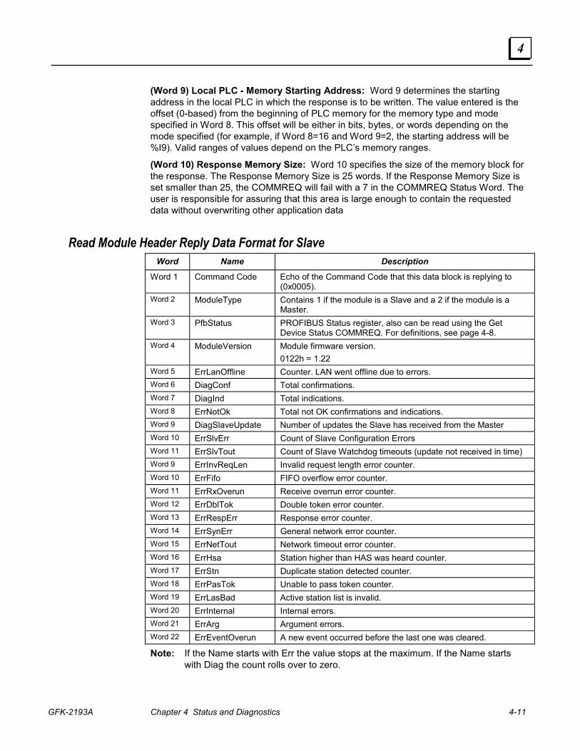
(Word 10) Response Memory Size: Word 10 specifies the size of the memory block for the response. The Response Memory Size is 25 words. If the Response Memory Size is set smaller than 25, the COMMREQ will fail with a 7 in the COMMREQ Status Word. The user is responsible for assuring that this area is large enough to contain the requested data without overwriting other application data
Read Module Header Reply Data Format for Slave Word Name Description
Word 1 Command Code Echo of the Command Code that this data block is replying to (0x0005).
Word 2 ModuleType Contains 1 if the module is a Slave and a 2 if the module is a Master.
Word 3 PfbStatus PROFIBUS Status register, also can be read using the Get Device Status COMMREQ. For definitions, see page 4-8.
Word 4 ModuleVersion Module firmware version. 0122h = 1.22
Word 5 ErrLanOffline Counter. LAN went offline due to errors. Word 6 DiagConf Total confirmations. Word 7 DiagInd Total indications. Word 8 ErrNotOk Total not OK confirmations and indications. Word 9 DiagSlaveUpdate Number of updates the Slave has received from the Master Word 10 ErrSlvErr Count of Slave Configuration Errors Word 11 ErrSlvTout Count of Slave Watchdog timeouts (update not received in time) Word 9 ErrInvReqLen Invalid request length error counter. Word 10 ErrFifo FIFO overflow error counter. Word 11 ErrRxOverun Receive overrun error counter. Word 12 ErrDblTok Double token error counter. Word 13 ErrRespErr Response error counter. Word 14 ErrSynErr General network error counter. Word 15 ErrNetTout Network timeout error counter. Word 16 ErrHsa Station higher than HAS was heard counter. Word 17 ErrStn Duplicate station detected counter. Word 18 ErrPasTok Unable to pass token counter. Word 19 ErrLasBad Active station list is invalid. Word 20 ErrInternal Internal errors. Word 21 ErrArg Argument errors. Word 22 ErrEventOverun A new event occurred before the last one was cleared.
Note: If the Name starts with Err the value stops at the maximum. If the Name starts with Diag the count rolls over to zero.
4-12 Series 90™-30 PROFIBUS Slave Module User's Manual – August 2004 GFK-2193A
4
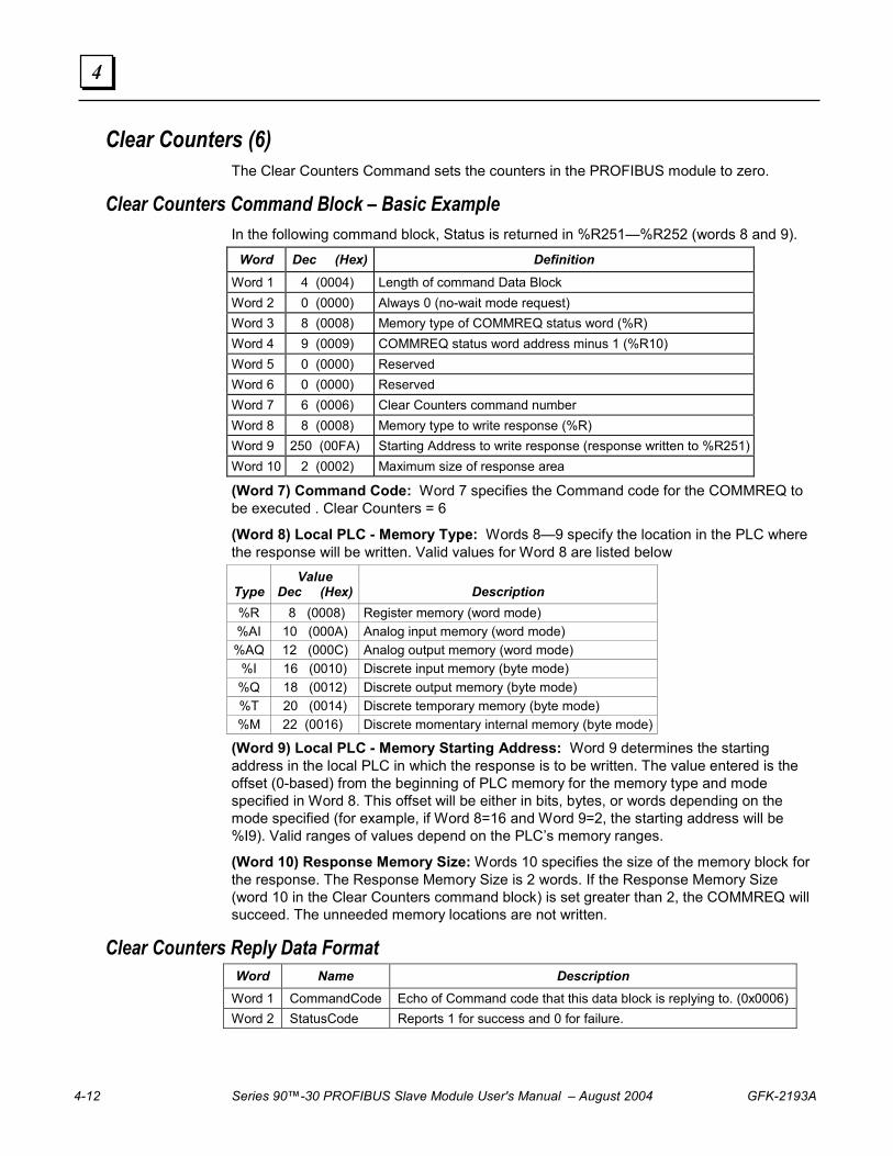
Clear Counters (6) The Clear Counters Command sets the counters in the PROFIBUS module to zero.
Clear Counters Command Block – Basic Example In the following command block, Status is returned in %R251—%R252 (words 8 and 9).
Word Dec (Hex) Definition Word 1 4 (0004) Length of command Data Block Word 2 0 (0000) Always 0 (no-wait mode request) Word 3 8 (0008) Memory type of COMMREQ status word (%R) Word 4 9 (0009) COMMREQ status word address minus 1 (%R10) Word 5 0 (0000) Reserved Word 6 0 (0000) Reserved Word 7 6 (0006) Clear Counters command number Word 8 8 (0008) Memory type to write response (%R) Word 9 250 (00FA) Starting Address to write response (response written to %R251)Word 10 2 (0002) Maximum size of response area
(Word 7) Command Code: Word 7 specifies the Command code for the COMMREQ to be executed . Clear Counters = 6
(Word 8) Local PLC - Memory Type: Words 8—9 specify the location in the PLC where the response will be written. Valid values for Word 8 are listed below
Type
Value Dec (Hex)
Description
%R 8 (0008) Register memory (word mode) %AI 10 (000A) Analog input memory (word mode) %AQ 12 (000C) Analog output memory (word mode)
%I 16 (0010) Discrete input memory (byte mode) %Q 18 (0012) Discrete output memory (byte mode) %T 20 (0014) Discrete temporary memory (byte mode) %M 22 (0016) Discrete momentary internal memory (byte mode)
(Word 9) Local PLC - Memory Starting Address: Word 9 determines the starting address in the local PLC in which the response is to be written. The value entered is the offset (0-based) from the beginning of PLC memory for the memory type and mode specified in Word 8. This offset will be either in bits, bytes, or words depending on the mode specified (for example, if Word 8=16 and Word 9=2, the starting address will be %I9). Valid ranges of values depend on the PLC’s memory ranges.
(Word 10) Response Memory Size: Words 10 specifies the size of the memory block for the response. The Response Memory Size is 2 words. If the Response Memory Size (word 10 in the Clear Counters command block) is set greater than 2, the COMMREQ will succeed. The unneeded memory locations are not written.
Clear Counters Reply Data Format Word Name Description
Word 1 CommandCode Echo of Command code that this data block is replying to. (0x0006) Word 2 StatusCode Reports 1 for success and 0 for failure.
Index
GFK-2193A Index-1
C Clear Counters (6), 4-12 COMMREQs
Clear Counters (6), 4-12 Get Slave Status
details, 4-7 memory types, 4-7
PROFIBUS Master, 4-7 Read Module Header (5), 4-10
COMMREQs, general information, 4-3 error detection and handling, 4-5 ladder instruction, 4-3 operation, 4-4 programming recommendations, 4-5 status word, 4-6
Configuration, 3-1 software, 1-2
CPU version, 1-2
F Features, 1-2
G Get Slave Status
details, 4-7 memory types, 4-7
I Indicators, 4-1 Installation procedures
installing bus termination, 2-3 installing the module in the rack, 2-1 reviewing system power requirements, 2-1
L LEDs, 4-1
M Mounting location, 1-2
P Pin-out
PROFIBUS bus plug connector, 1-5 Power consumption, 1-2 Power supplies, 2-1 PROFIBUS
baud rate, 2-4 bus communication, 1-3
network connectors, 1-5 network overview, 1-3 network topology, 1-4 standards, 1-1
R Read Module Header, 4-10 Reviewing system power requirements,
2-1
S Selecting the proper line type, 2-2 Specifications, 1-2
environment, 1-2 power consumption, 1-2
Standards PROFIBUS, 1-1
Status and diagnostic methods, 4-1 Status information, 1-2 Status Word codes, 4-6 Status/firmware ID array, 4-2