ge 60 vs-vsx 1 1 0 7 340609003 - gb - mosa 60 vsx.pdfdesign, production and servicing of engine...
TRANSCRIPT
GE 60 VS-VSX
340609003 - GB1 1 0 7
04/10/07 34060M00
Preparato da UPTApprovato da DITE
USE AND MAINTENANCE MANUALSPARE PARTS CATALOG
Quality system GE_, MS_, TS_, EAS_M01
© MOSA 1.2-05/03
UNI EN ISO 9001 : 2000
10/1
0/02
M01
-GB
MOSA has certified its quality system according toUNI EN ISO 9001:2000 to ensure a constant, highquality of its products. This certification covers thedesign, production and servicing of engine drivenwelders and generating sets.
The certifying institute, ICIM, which is a member ofthe International Certification Network IQNet,awarded the official approval to MOSA after anexamination of its operations at the head office andplant in Cusago (MI), Italy.
This certification is not a point of arrival but a pledgeon the part of the entire company to maintain a levelof quality of both its products and services whichwill continue to satisfy the needs of its clients, aswell as to improve the transparency and thecommunications regarding all the company’s activesin accordance with the official procedures and inharmony with the MOSA Manual of Quality.
The advantages for MOSA clients are:
· Constant quality of products and services at thehigh level which the client expects;
· Continuous efforts to improve the products andtheir performance at competitive conditions;
· Competent support in the solution of problems;
· Information and training in the correct applicationand use of the products to assure the security ofthe operator and protect the environment;
· Regular inspections by ICIM to confirm that therequirements of the company’s quality systemand ISO 9001 are being respected.
All these advantages are guaranteed by theCERTIFICATE OF QUALITY SYSTEM No.0192issued by ICIM S.p.A. - Milano (Italy ) - www.icim.it
INDEX GE 60 VS/VSXM1
© MOSA REV.1-11/07
M 01 QUALITY SYSTEMM 1.01 COPYRIGHTM 1.1 NOTESM 1.4 CE MARKM 1.5 TECHNICAL DATAM 2 - 2.1 SYMBOLS AND SAFETY PRECAUTIONSM 2.5 INSTALLATION AND ADVICE BEFORE USEM 2.6 INSTALLATION AND ADVICEM 2.7 INSTALLATIONM 3 UNPACKINGM 4 TRANSPORT AND DISPLACEMENTSM 6.8 ASSEMBLY: CTL 50M 20 PREPARING THE UNITM 21 START AND STOPM 30 CONTROLS LEGENDM 31 CONTROLSM 37 -….. USING THE GENERATORM 38.5.1 TCM 40 REMOTE CONTROLM 39.10 INSULATION MONITORING PROTECTIONM 39.11 EARTH LEAKAGE RELAYM 39.12 EP6 ENGINE PROTECTIONM 40.2 TROUBLESHOOTINGM 43 MAINTENANCEM 45 STORAGEM 46 CUST OFFM 53 DIMENSIONSM 60 ELECTRICAL SYSTEM LEGENDEM 61-….. ELECTRICAL SYSTEM
R 1 SPARE PARTS LISTIG... SPARE PARTS
04/1
0/07
340
60-G
B
Copyright GE_, MS_, TS_, EASM
1.01© MOSA 1.0-10/02
ATTENTION
© All rights are reserved to said Company.
It is a property logo of MOSA division of B.C.S.S.p.A. All other possible logos contained in thedocumentation are registered by the respectiveowners.
➠ The reproduction and total or partial use, in anyform and/or with any means, of thedocumentation is allowed to nobody without awritten permission by MOSA division of B.C.S.S.p.A.
To this aim is reminded the protection of the author’sright and the rights connected to the creation anddesign for communication, as provided by the lawsin force in the matter.
In no case MOSA division of B.C.S. S.p.A. will beheld responsible for any damaga, direct or indirect,in relation with the use of the given information.
MOSA division of B.C.S. S.p.A. does not take anyresponsibility about the shown information on firmsor individuals, but keeps the right to refuse servicesor information publication which it judges discutible,unright or illegal.
10/1
0/02
M1-
01-G
B
This use and maintenance manual is an importantpart of the machines in question.The assistance and maintenance personel mustkeep said manual at disposal, as well as that forthe engine and alternator (if the machine issynchronous) and all other documentation about themachine.
We advise you to pay attention to the pagesconcerning the security (see page M1.1).
INFORMATION
Dear Customer,We wish to thank you for having bought fromMOSA a high quality set.
Our sections for Technical Service and SpareParts will work at best to help you if it werenecessary.
To this purpose we advise you, for all control andoverhaul operations, to turn to the nearestauthorized Service Centre, where you will obtaina prompt and specialized intervention.
☞ In case you do not profit on these Services andsome parts are replaced, please ask and besure that are used exclusively original MOSAparts; this to guarantee that the performancesand the initial safety prescribed by the norms inforce are re-established.
☞ The use of non original spare parts will cancelimmediately any guarantee and Technical Ser-vice obligation from MOSA.
NOTES ABOUT THE MANUALBefore actioning the machine please read thismanual attentively. Follow the instructionscontained in it, in this way you will avoidinconveniences due to negligence, mistakes orincorrect maintenance. The manual is for qualifiedpersonnel, who knows the rules: about safety andhealth, installation and use of sets movable aswell as fixed.
You must remember that, in case you havedifficulties for use or installation or others, ourTechnical Service is always at your disposal forexplanations or interventions.
The manual for Use Maintenance and Spare Partsis an integrant part of the product. It must be keptwith care during all the life of the product.In case the machine and/or the set should beyielded to another user, this manual must alsogiven to him.Do not damage it, do not take parts away, do nottear pages and keep it in places protected fromdampness and heat.
You must take into account that some figurescontained in it want only to identify the describedparts and therefore might not correspond to themachine in your possession.
INFORMATION OF GENERAL TYPE
In the envelope given together with the machineand/or set you will find: the manual for UseMaintenance and Spare Parts, the manual foruse of the engine and the tools (if included in theequipment), the guarantee (in the countries whereit is prescribed by law).
Our products have been designed for the use ofgeneration for welding, electric and hydraulicsystem; ANY OTHER DIFFERENT USE NOTINCLUDED IN THE ONE INDICATED, relievesMOSA from the risks which could happen or,anyway, from that which was agreed when sellingthe machine; MOSA excludes any responsibilityfor damages to the machine, to the things or topersons in this case.
Our products are made in conformity with thesafety norms in force, for which it is advisable touse all these devices or information so that theuse does not bring damage to persons or things.
While working it is advisable to keep to thepersonal safety norms in force in the countries towhich the product is destined (clothing, work tools,etc.).
Do not modify for any motive parts of the machine(fastenings, holes, electric or mechanical devices,others..) if not duly authorized in writing by MOSA:the responsibility coming from any potentialintervention will fall on the executioner as in facthe becomes maker of the machine.
Notes GE_, MS_, TS_, EAS_M
1-1© MOSA 1.0-10/02
☞ Notice: this manual does not engage MOSA,who keeps the faculty, apart the essentialcharacteristics of the model here described andillustrated, to bring betterments and modificationsto parts and accessories, without putting thismanual uptodate immediately.
10/1
0/02
M 1
-1 G
B
CE MARKM
1.4© MOSA REV.4-10/07
10/1
0/02
M1-
4 G
B
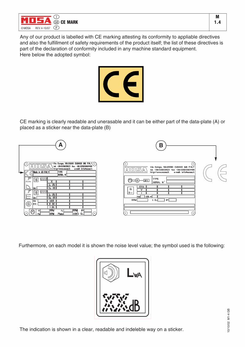
Any of our product is labelled with CE marking attesting its conformity to appliable directivesand also the fulfillment of safety requirements of the product itself; the list of these directives ispart of the declaration of conformity included in any machine standard equipment.Here below the adopted symbol:
CE marking is clearly readable and unerasable and it can be either part of the data-plate (A) orplaced as a sticker near the data-plate (B)
A B
Furthermore, on each model it is shown the noise level value; the symbol used is the following:
The indication is shown in a clear, readable and indeleble way on a sticker.
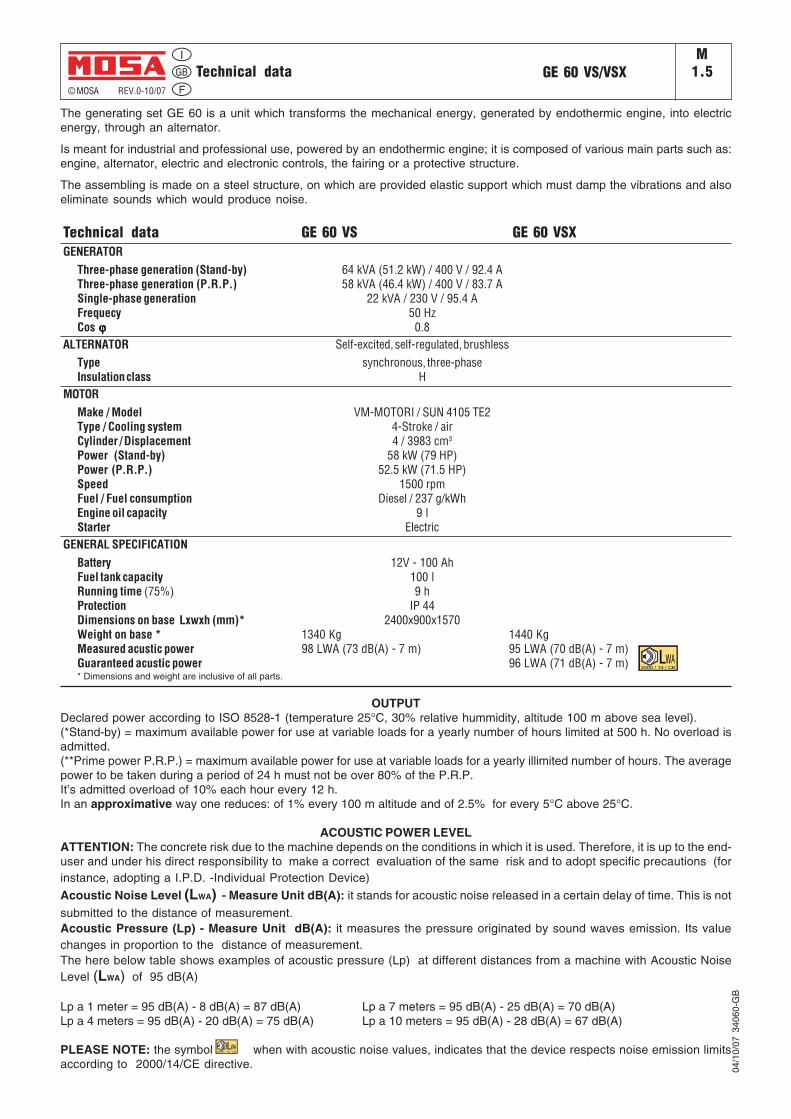
The generating set GE 60 is a unit which transforms the mechanical energy, generated by endothermic engine, into electricenergy, through an alternator.
Is meant for industrial and professional use, powered by an endothermic engine; it is composed of various main parts such as:engine, alternator, electric and electronic controls, the fairing or a protective structure.
The assembling is made on a steel structure, on which are provided elastic support which must damp the vibrations and alsoeliminate sounds which would produce noise.
Technical data GE 60 VS GE 60 VSXGENERATOR
Three-phase generation (Stand-by) 64 kVA (51.2 kW) / 400 V / 92.4 AThree-phase generation (P.R.P.) 58 kVA (46.4 kW) / 400 V / 83.7 ASingle-phase generation 22 kVA / 230 V / 95.4 AFrequecy 50 HzCos ϕϕϕϕϕ 0.8
ALTERNATOR Self-excited, self-regulated, brushlessType synchronous, three-phaseInsulation class H
MOTORMake / Model VM-MOTORI / SUN 4105 TE2Type / Cooling system 4-Stroke / airCylinder / Displacement 4 / 3983 cm3
Power (Stand-by) 58 kW (79 HP)Power (P.R.P.) 52.5 kW (71.5 HP)Speed 1500 rpmFuel / Fuel consumption Diesel / 237 g/kWhEngine oil capacity 9 lStarter Electric
GENERAL SPECIFICATIONBattery 12V - 100 AhFuel tank capacity 100 lRunning time (75%) 9 hProtection IP 44Dimensions on base Lxwxh (mm)* 2400x900x1570Weight on base * 1340 Kg 1440 KgMeasured acustic power 98 LWA (73 dB(A) - 7 m) 95 LWA (70 dB(A) - 7 m)Guaranteed acustic power 96 LWA (71 dB(A) - 7 m)* Dimensions and weight are inclusive of all parts.
© MOSA REV.0-10/07
GE 60 VS/VSXM
1.5Technical data
04/1
0/07
340
60-G
B
OUTPUTDeclared power according to ISO 8528-1 (temperature 25°C, 30% relative hummidity, altitude 100 m above sea level).(*Stand-by) = maximum available power for use at variable loads for a yearly number of hours limited at 500 h. No overload isadmitted.(**Prime power P.R.P.) = maximum available power for use at variable loads for a yearly illimited number of hours. The averagepower to be taken during a period of 24 h must not be over 80% of the P.R.P.It’s admitted overload of 10% each hour every 12 h.In an approximative way one reduces: of 1% every 100 m altitude and of 2.5% for every 5°C above 25°C.
ACOUSTIC POWER LEVELATTENTION: The concrete risk due to the machine depends on the conditions in which it is used. Therefore, it is up to the end-user and under his direct responsibility to make a correct evaluation of the same risk and to adopt specific precautions (forinstance, adopting a I.P.D. -Individual Protection Device)
Acoustic Noise Level (LWA) - Measure Unit dB(A): it stands for acoustic noise released in a certain delay of time. This is not
submitted to the distance of measurement.Acoustic Pressure (Lp) - Measure Unit dB(A): it measures the pressure originated by sound waves emission. Its valuechanges in proportion to the distance of measurement.The here below table shows examples of acoustic pressure (Lp) at different distances from a machine with Acoustic NoiseLevel (LWA) of 95 dB(A)
Lp a 1 meter = 95 dB(A) - 8 dB(A) = 87 dB(A) Lp a 7 meters = 95 dB(A) - 25 dB(A) = 70 dB(A)Lp a 4 meters = 95 dB(A) - 20 dB(A) = 75 dB(A) Lp a 10 meters = 95 dB(A) - 28 dB(A) = 67 dB(A)
PLEASE NOTE: the symbol when with acoustic noise values, indicates that the device respects noise emission limitsaccording to 2000/14/CE directive.
2000 / 14 / CE
2000 / 14 / CE
SYMBOLS AND SAFETY PRECAUTIONS GE_, MS_, TS_M2
© MOSA 1.0-11/99
SYMBOLS IN THIS MANUAL
- The symbols used in this manual are designed to callyour attention to important aspects of the operation ofthe machine as well as potential hazards and dangersfor persons and things.
IMPORTANT ADVICE
- Advice to the User about the safety:
☞ N.B.: The information contained in the manual canbe changed without notice.Potential damages caused in relation to the use ofthese instructions will not be considered becausethese are only indicative.Remember that the non observance of theindications reported by us might cause damage topersons or things.It is understood, that local dispositions and/or lawsmust be respected.
WARNING
Situations of danger - no harm to personsor things
Do not use without protective devices providedRemoving or disabling protective devices on themachine is prohibited.
Do not use the machine if it is not in good technicalconditionThe machine must be in good working order beforebeing used. Defects, especially those which regardthe safety of the machine, must be repaired beforeusing the machine.
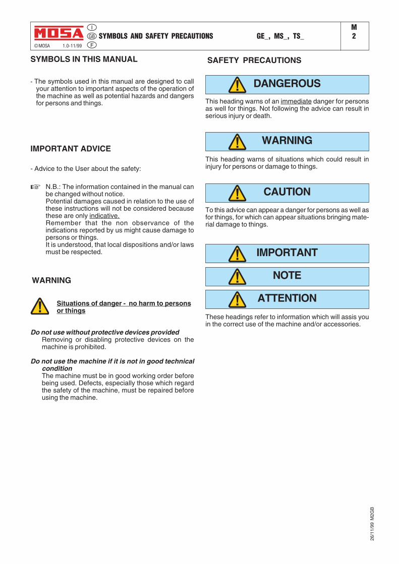
SAFETY PRECAUTIONS
This heading warns of an immediate danger for personsas well for things. Not following the advice can result inserious injury or death.
This heading warns of situations which could result ininjury for persons or damage to things.
To this advice can appear a danger for persons as well asfor things, for which can appear situations bringing mate-rial damage to things.
These headings refer to information which will assis youin the correct use of the machine and/or accessories.
ATTENTION
NOTE
IMPORTANT
CAUTION
WARNING
DANGEROUS
26/1
1/99
M2G
B
SYMBOLS AND SAFETY PRECAUTIONS GE_, MS_, TS_M
2-1© MOSA 1.1-04/03
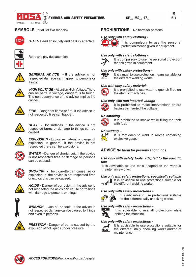
SYMBOLS (for all MOSA models)
STOP - Read absolutely and be duly attentive
Read and pay due attention
GENERAL ADVICE - If the advice is notrespected damage can happen to persons orthings.
HIGH VOLTAGE - Attention High Voltage.Therecan be parts in voltage, dangerous to touch.The non observance of the advice implies lifedanger.
FIRE - Danger of flame or fire. If the advice isnot respected fires can happen.
HEAT - Hot surfaces. If the advice is notrespected burns or damage to things can becaused.
EXPLOSION - Explosive material or danger ofexplosion. in general. If the advice is notrespected there can be explosions.
WATER - Danger of shortcircuit. If the adviceis not respected fires or damage to personscan be caused.
SMOKING - The cigarette can cause fire orexplosion. If the advice is not respected firesor explosions can be caused.
ACIDS - Danger of corrosion. If the advice isnot respected the acids can cause corrosionswith damage to persons or things.
WRENCH - Use of the tools. If the advice isnot respected damage can be caused to thingsand even to persons.
PRESSION - Danger of burns caused by theexpulsion of hot liquids under pressure.
PROHIBITIONS No harm for persons
Use only with safety clothing -It is compulsory to use the personalprotection means given in equipment.
Use only with safety clothing -It is compulsory to use the personal protectionmeans given in equipment.
Use only with safety protections -It is a must to use protection means suitable forthe different welding works.
Use with only safety material -It is prohibited to use water to quench fires onthe electric machines.
Use only with non inserted voltage -It is prohibited to make interventions beforehaving disinserted the voltage.
No smoking -It is prohibited to smoke while filling the tankwith fuel.
No welding -It is forbidden to weld in rooms containingexplosive gases.
ADVICE No harm for persons and things
Use only with safety tools, adapted to the specificuse -It is advisable to use tools adapted to the variousmaintenance works.
Use only with safety protections, specifically suitableIt is advisable to use protections suitable forthe different welding works.
Use only with safety protections -It is advisable to use protections suitablefor the different daily checking works.
Use only with safety protections -It is advisable to use all protections whileshifting the machine.
Use only with safety protections -It is advisable to use protections suitable forthe different daily checking works.and/or ofmaintenance.
26/1
1/99
M2-
1GB
ACCES FORBIDDEN to non authorizad peaple.
INSTALLATION AND ADVICE BEFORE USE GE_, MS_, TS_M
2-5© MOSA 1.0-06/00
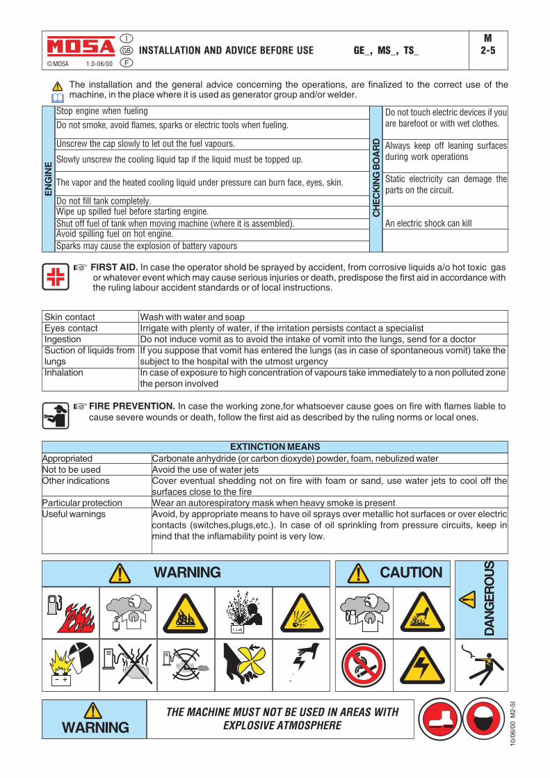
Stop engine when fueling
ENG
INE
CH
ECK
ING
BO
AR
D
Do not touch electric devices if youare barefoot or with wet clothes.
Always keep off leaning surfacesduring work operations
Static electricity can demage theparts on the circuit.
An electric shock can kill
The installation and the general advice concerning the operations, are finalized to the correct use of themachine, in the place where it is used as generator group and/or welder.
☞ FIRST AID. In case the operator shold be sprayed by accident, from corrosive liquids a/o hot toxic gasor whatever event which may cause serious injuries or death, predispose the first aid in accordance withthe ruling labour accident standards or of local instructions.
Skin contactEyes contactIngestionSuction of liquids fromlungsInhalation
Wash with water and soapIrrigate with plenty of water, if the irritation persists contact a specialistDo not induce vomit as to avoid the intake of vomit into the lungs, send for a doctorIf you suppose that vomit has entered the lungs (as in case of spontaneous vomit) take thesubject to the hospital with the utmost urgencyIn case of exposure to high concentration of vapours take immediately to a non polluted zonethe person involved
☞ FIRE PREVENTION. In case the working zone,for whatsoever cause goes on fire with flames liable tocause severe wounds or death, follow the first aid as described by the ruling norms or local ones.
AppropriatedNot to be usedOther indications
Particular protectionUseful warnings
Carbonate anhydride (or carbon dioxyde) powder, foam, nebulized waterAvoid the use of water jetsCover eventual shedding not on fire with foam or sand, use water jets to cool off thesurfaces close to the fireWear an autorespiratory mask when heavy smoke is presentAvoid, by appropriate means to have oil sprays over metallic hot surfaces or over electriccontacts (switches,plugs,etc.). In case of oil sprinkling from pressure circuits, keep inmind that the inflamability point is very low.
EXTINCTION MEANS
WARNING CAUTION
DANG
ERO
US
WARNINGTHE MACHINE MUST NOT BE USED IN AREAS WITH
EXPLOSIVE ATMOSPHERE
10/0
6/00
M2-
5I
Do not smoke, avoid flames, sparks or electric tools when fueling.
Unscrew the cap slowly to let out the fuel vapours.
Slowly unscrew the cooling liquid tap if the liquid must be topped up.
The vapor and the heated cooling liquid under pressure can burn face, eyes, skin.
Do not fill tank completely.Wipe up spilled fuel before starting engine.Shut off fuel of tank when moving machine (where it is assembled).Avoid spilling fuel on hot engine.Sparks may cause the explosion of battery vapours
INSTALLATION AND ADVICEM
2.6© MOSA REV.1-06/07
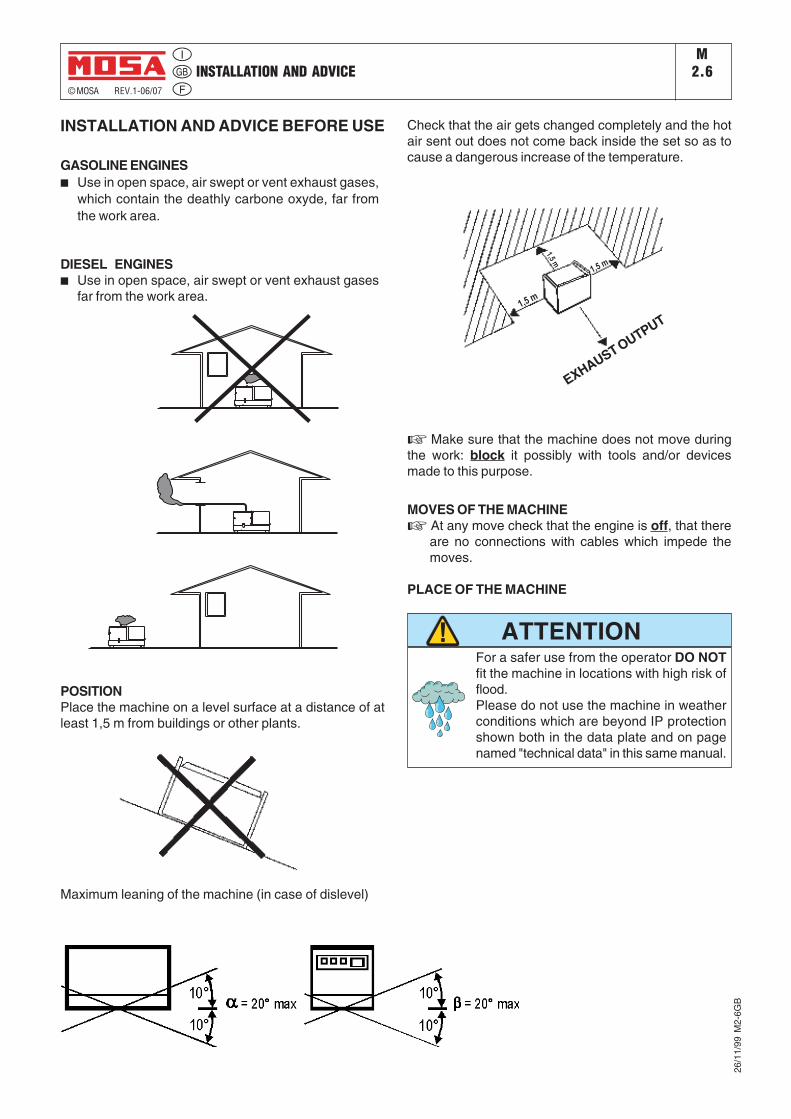
INSTALLATION AND ADVICE BEFORE USE
GASOLINE ENGINES■ Use in open space, air swept or vent exhaust gases,
which contain the deathly carbone oxyde, far fromthe work area.
DIESEL ENGINES■ Use in open space, air swept or vent exhaust gases
far from the work area.
POSITIONPlace the machine on a level surface at a distance of atleast 1,5 m from buildings or other plants.
Check that the air gets changed completely and the hotair sent out does not come back inside the set so as tocause a dangerous increase of the temperature.
☞ Make sure that the machine does not move duringthe work: block it possibly with tools and/or devicesmade to this purpose.
Maximum leaning of the machine (in case of dislevel)
26/1
1/99
M2-
6GB
1,5 m
1,5 m
1,5m
GAS DI SCARICO
EXHAUST OUTPUT
MOVES OF THE MACHINE☞ At any move check that the engine is off, that there
are no connections with cables which impede themoves.
PLACE OF THE MACHINE
ATTENTIONFor a safer use from the operator DO NOTfit the machine in locations with high risk offlood.Please do not use the machine in weatherconditions which are beyond IP protectionshown both in the data plate and on pagenamed "technical data" in this same manual.
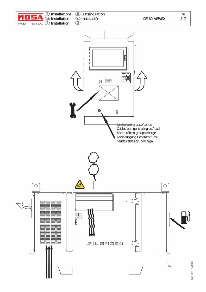
InstallazioneInstallationInstallation
GE 60 VS/VSXM
2.7© MOSA REV.0-10/07
04/1
0/07
340
60-I
LuftzirkulationInstalaciónE
D
NL
Uscita cavi gruppo/caricoCables out, generating set/loadSortie câbles groupe/chargeKabelausgang Generator/LastSalida cables grupo/carga
WARNUNG
ATTENTION
ATTENTION
ATTENZIONEFermare il motore prima di
effettuare qualsiasi manutenzione
Arreter le moteur avant
d'effectuer toute manutention
Stop the engine before
making any maintenance
Motor abstellen, bevor man
die Wartung durchfuhrt
:
EM
ERGEN
CY
I. CL.
TYPE
SERIAL N°
RPM
Hz COS ø
IP
UNPACKING GE_, MS_, TS_M3
© MOSA 1.1-02/04
NOTE
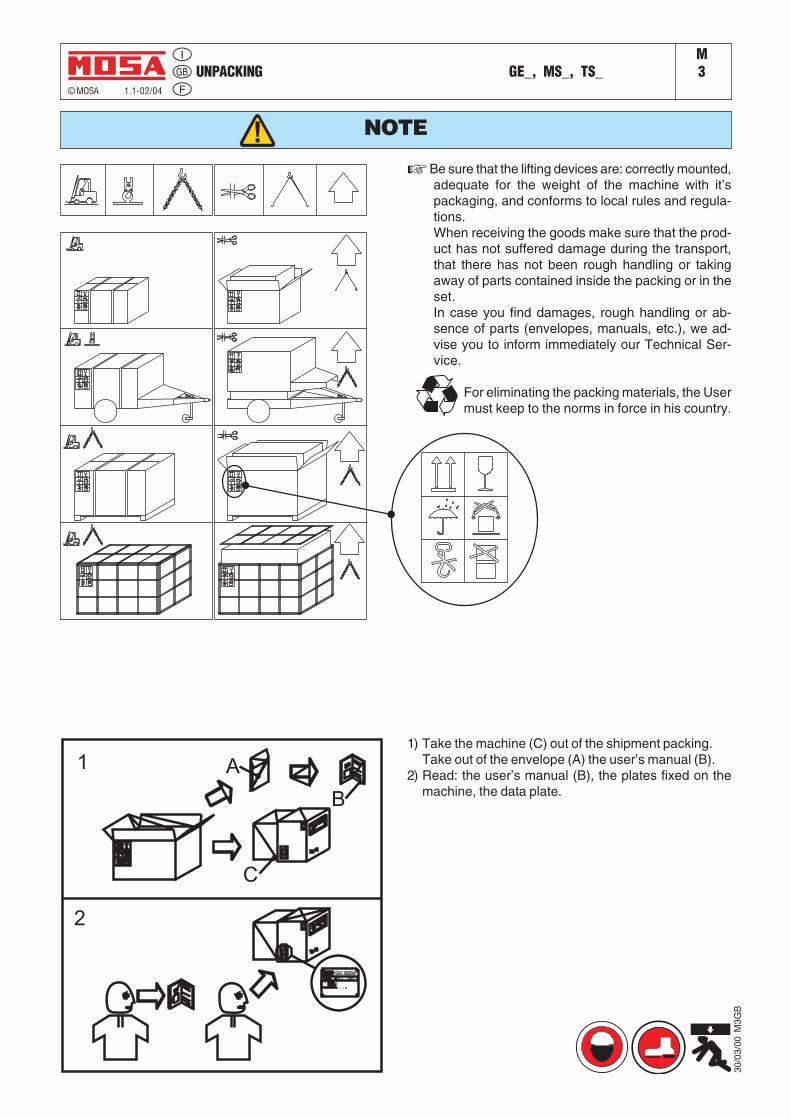
☞ Be sure that the lifting devices are: correctly mounted,adequate for the weight of the machine with it’spackaging, and conforms to local rules and regula-tions.When receiving the goods make sure that the prod-uct has not suffered damage during the transport,that there has not been rough handling or takingaway of parts contained inside the packing or in theset.In case you find damages, rough handling or ab-sence of parts (envelopes, manuals, etc.), we ad-vise you to inform immediately our Technical Ser-vice.
For eliminating the packing materials, the Usermust keep to the norms in force in his country.
1) Take the machine (C) out of the shipment packing.Take out of the envelope (A) the user’s manual (B).
2) Read: the user’s manual (B), the plates fixed on themachine, the data plate.
30/0
3/00
M3G
B
TRANSPORT AND DISPLACEMENTS COVERED UNITS AND SKID GE_, MS_, TS_M
4-2© MOSA 1.0-03/00
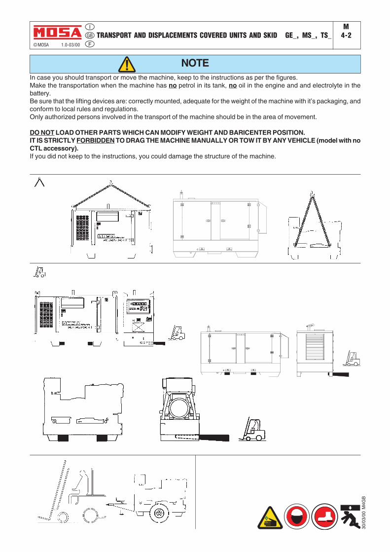
NOTEIn case you should transport or move the machine, keep to the instructions as per the figures.Make the transportation when the machine has no petrol in its tank, no oil in the engine and and electrolyte in thebattery.Be sure that the lifting devices are: correctly mounted, adequate for the weight of the machine with it’s packaging, andconform to local rules and regulations.Only authorized persons involved in the transport of the machine should be in the area of movement.
DO NOT LOAD OTHER PARTS WHICH CAN MODIFY WEIGHT AND BARICENTER POSITION.IT IS STRICTLY FORBIDDEN TO DRAG THE MACHINE MANUALLY OR TOW IT BY ANY VEHICLE (model with noCTL accessory).If you did not keep to the instructions, you could damage the structure of the machine.
30/0
3/00
M4G
B
ASSEMBLYCTL 35 -45 - 50 - 95
© MOSA 1.1-04/06
M6.8
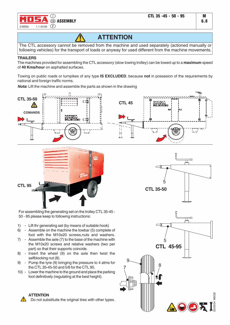
For assembling the generating set on the trolley CTL 35-45 -50 - 95 please keep to following instructions:
1) - Lift thr generating set (by means of suitable hook)6) - Assemble on the machine the towbar (5) complete of
foot with the M10x20 screws,nuts and washers.7) - Assemble the axle (7) to the base of the machine with
the M10x20 screws and relative washers (two perpart) so that their supports coincide.
8) - Insert the wheel (9) on the axle then twist theselfblocking nut (8).
9) - Pump the tyre (9) bringing the pressure to 4 atms forthe CTL 35-45-50 and 5/6 for the CTL 95.
10) - Lower the machine to the ground and place the parkingfoot definitively (regulating at the best height).
ATTENTION Do not substituite the original tires with other types.
ATTENTION
78
9
CTL 35-50CTL 45
COMANDS
5
5
CTL 35-50
CTL 45-95
CTL 95
30/0
3/04
M6G
B
The CTL accessory cannot be removed from the machine and used separately (actioned manually orfollowing vehicles) for the transport of loads or anyway for used different from the machine movements.
TRAILERSThe machines provided for assembling the CTL accessory (slow towing trolley) can be towed up to a maximum speedof 40 Kms/hour on asphalted surfaces.
Towing on public roads or turnpikes of any type IS EXCLUDED, because not in possesion of the requirements bynational and foreign traffic norms.Nota: Lift the machine and assemble the parts as shown in the drawing
Set-up for operation (Engine diesel)TS_GEAir cooled systems
M20
© MOSA 1.1-09/05
16/0
7/03
M20
-R-A
-GB
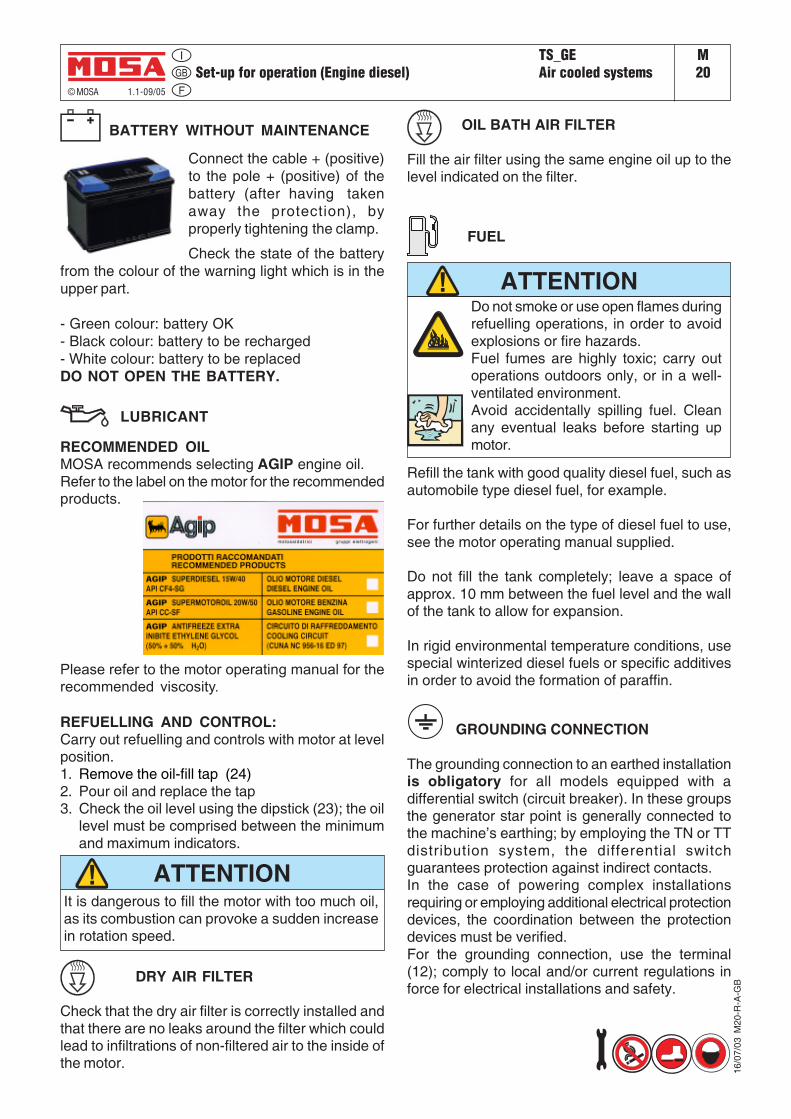
BATTERY WITHOUT MAINTENANCE
Connect the cable + (positive)to the pole + (positive) of thebattery (after having takenaway the protection), byproperly tightening the clamp.
Check the state of the batteryfrom the colour of the warning light which is in theupper part.
- Green colour: battery OK- Black colour: battery to be recharged- White colour: battery to be replacedDO NOT OPEN THE BATTERY.
RECOMMENDED OILMOSA recommends selecting AGIP engine oil.Refer to the label on the motor for the recommendedproducts.
LUBRICANT
Please refer to the motor operating manual for therecommended viscosity.
It is dangerous to fill the motor with too much oil,as its combustion can provoke a sudden increasein rotation speed.
ATTENTION
FUEL
Do not smoke or use open flames duringrefuelling operations, in order to avoidexplosions or fire hazards.Fuel fumes are highly toxic; carry outoperations outdoors only, or in a well-ventilated environment.Avoid accidentally spilling fuel. Cleanany eventual leaks before starting upmotor.
ATTENTION
Refill the tank with good quality diesel fuel, such asautomobile type diesel fuel, for example.
For further details on the type of diesel fuel to use,see the motor operating manual supplied.
Do not fill the tank completely; leave a space ofapprox. 10 mm between the fuel level and the wallof the tank to allow for expansion.
In rigid environmental temperature conditions, usespecial winterized diesel fuels or specific additivesin order to avoid the formation of paraffin.
GROUNDING CONNECTION
The grounding connection to an earthed installationis obligatory for all models equipped with adifferential switch (circuit breaker). In these groupsthe generator star point is generally connected tothe machine’s earthing; by employing the TN or TTdistribution system, the differential switchguarantees protection against indirect contacts.In the case of powering complex installationsrequiring or employing additional electrical protectiondevices, the coordination between the protectiondevices must be verified.For the grounding connection, use the terminal(12); comply to local and/or current regulations inforce for electrical installations and safety.
REFUELLING AND CONTROL:Carry out refuelling and controls with motor at levelposition.1. Remove the oil-fill tap (24)2. Pour oil and replace the tap3. Check the oil level using the dipstick (23); the oil
level must be comprised between the minimumand maximum indicators.
DRY AIR FILTER
Check that the dry air filter is correctly installed andthat there are no leaks around the filter which couldlead to infiltrations of non-filtered air to the inside ofthe motor.
OIL BATH AIR FILTER
Fill the air filter using the same engine oil up to thelevel indicated on the filter.
© MOSA REV.0-10/07
04/1
0/07
340
60-G
B
GE 20-55-65 PS/PSXGE 35 PS - GE 85-115 PSXGE 60 VS/VSX
M21START AND STOP
NOTE
CAUTION
MACHINE WITH EMERGENCY BUTTON
Pressing the button the engine will stopimmediately in any working condition.
CAUTION
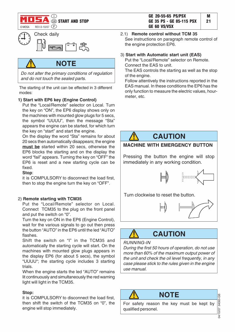
The starting of the unit can be effected in 3 differentmodes:
1) Start with EP6 key (Engine Control)Put the “Local/Remote” selector on Local. Turnthe key on “ON”, the EP6 display shows only onthe machines with mounted glow plugs for 5 secs,the symbol “UUUU”, then the message “Sta”appears the engine can be started, for which turnthe key on “start” and start the engine.On the display the word “Sta” remains for about20 secs then automatically disappears; the enginemust be started within 20 secs, otherwise theEP6 blocks the starting and on the display theword “fail” appears. Turning the key on “OFF” theEP6 is reset and a new starting cycle can befixed.Stop:it is COMPULSORY to disconnect the load first,then to stop the engine turn the key on “OFF”.
2) Remote starting with TCM35Put the “Local/Remote” selector on Local.Connect TCM35 to the plug on the front paneland put the switch on “0”.Turn the key on ON in the EP6 (Engine Control),wait for the various signals to go out then pressthe button “AUTO” in the EP6 until the led “AUTO”flashes.Shift the switch on “I” in the TCM35 andautomatically the starting cycle will start. On themachines with mounted glow plugs appears inthe display EP6 (for about 5 secs), the symbol“UUUU“; the starting cycle includes 3 startingtrials.When the engine starts the led “AUTO” remainslit continuously and simultaneously the red warninglight will light in the TCM35.
Stop:it is COMPULSORY to disconnect the load first,then shift the switch of the TCM35 on “0”, theengine will stop immediately.
2.1) Remote control without TCM 35See instructions on paragraph remote control ofthe engine protection EP6.
3) Start with Automatic start unit (EAS)Put the “Local/Remote” selector on Remote.Connect the EAS to unit.The EAS controls the starting as well as the stopof the engine.Follow attentively the instructions reported in theEAS manual. In these conditions the EP6 has theonly function to measure the electric values, hour-meter, etc.
Turn clockwise to reset the button.
For safety reason the key must be kept byqualified personel.
NOTE
Do not alter the primary conditions of regulationand do not touch the sealed parts.
Check daily
RUNNING-INDuring the first 50 hours of operation, do not usemore than 60% of the maximum output power ofthe unit and check the oil level frequently, in anycase please stick to the rules given in the engineuse manual.
CONTROLS LEGENDE GE_, MS_, TS_M30
© MOSA 1.0-05/01
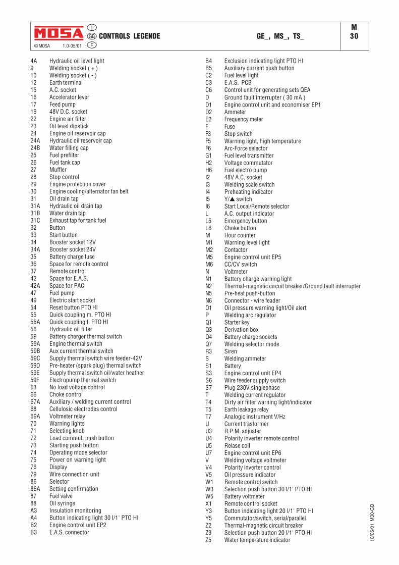
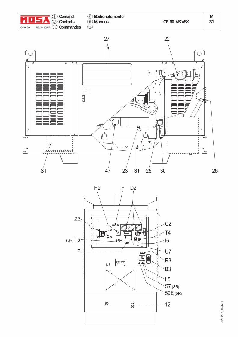
4A Hydraulic oil level light9 Welding socket ( + )10 Welding socket ( - )12 Earth terminal15 A.C. socket16 Accelerator lever17 Feed pump19 48V D.C. socket22 Engine air filter23 Oil level dipstick24 Engine oil reservoir cap24A Hydraulic oil reservoir cap24B Water filling cap25 Fuel prefilter26 Fuel tank cap27 Muffler28 Stop control29 Engine protection cover30 Engine cooling/alternator fan belt31 Oil drain tap31A Hydraulic oil drain tap31B Water drain tap31C Exhaust tap for tank fuel32 Button33 Start button34 Booster socket 12V34A Booster socket 24V35 Battery charge fuse36 Space for remote control37 Remote control42 Space for E.A.S.42A Space for PAC47 Fuel pump49 Electric start socket54 Reset button PTO HI55 Quick coupling m. PTO HI55A Quick coupling f. PTO HI56 Hydraulic oil filter59 Battery charger thermal switch59A Engine thermal switch59B Aux current thermal switch59C Supply thermal switch wire feeder-42V59D Pre-heater (spark plug) thermal switch59E Supply thermal switch oil/water heather59F Electropump thermal switch63 No load voltage control66 Choke control67A Auxiliary / welding current control68 Cellulosic electrodes control69A Voltmeter relay70 Warning lights71 Selecting knob72 Load commut. push button73 Starting push button74 Operating mode selector75 Power on warning light76 Display79 Wire connection unit86 Selector86A Setting confirmation87 Fuel valve88 Oil syringeA3 Insulation monitoringA4 Button indicating light 30 l/1' PTO HIB2 Engine control unit EP2B3 E.A.S. connector
B4 Exclusion indicating light PTO HIB5 Auxiliary current push buttonC2 Fuel level lightC3 E.A.S. PCBC6 Control unit for generating sets QEAD Ground fault interrupter ( 30 mA )D1 Engine control unit and economiser EP1D2 AmmeterE2 Frequency meterF FuseF3 Stop switchF5 Warning light, high temperatureF6 Arc-Force selectorG1 Fuel level transmitterH2 Voltage commutatorH6 Fuel electro pumpI2 48V A.C. socketI3 Welding scale switchI4 Preheating indicatorI5 Y/▲ switchI6 Start Local/Remote selectorL A.C. output indicatorL5 Emergency buttonL6 Choke buttonM Hour counterM1 Warning level lightM2 ContactorM5 Engine control unit EP5M6 CC/CV switchN VoltmeterN1 Battery charge warning lightN2 Thermal-magnetic circuit breaker/Ground fault interrupterN5 Pre-heat push-buttonN6 Connector - wire feaderO1 Oil pressure warning light/Oil alertP Welding arc regulatorQ1 Starter keyQ3 Derivation boxQ4 Battery charge socketsQ7 Welding selector modeR3 SirenS Welding ammeterS1 BatteryS3 Engine control unit EP4S6 Wire feeder supply switchS7 Plug 230V singlephaseT Welding current regulatorT4 Dirty air filter warning light/indicatorT5 Earth leakage relayT7 Analogic instrument V/HzU Current trasformerU3 R.P.M. adjusterU4 Polarity inverter remote controlU5 Relase coilU7 Engine control unit EP6V Welding voltage voltmeterV4 Polarity inverter controlV5 Oil pressure indicatorW1 Remote control switchW3 Selection push button 30 l/1' PTO HIW5 Battery voltmeterX1 Remote control socketY3 Button indicating light 20 l/1' PTO HIY5 Commutator/switch, serial/parallelZ2 Thermal-magnetic circuit breakerZ3 Selection push button 20 l/1' PTO HIZ5 Water temperature indicator 10
/05/
01 M
30-G
B
© MOSA REV.0-10/07
BedienelementeMandos GE 60 VS/VSX
M31
ComandiControlsCommandes
E
D
NL
H2 F D2
U7
T4
R3
B3
F
Z2
12
L5
(SR) T5
TANK0 4/4
FUSE
0.02
0.1
0.25
0.5
I° (A)I° (A)
TRIP2.5 ON
2
0.5
0.4
t (s)t (s)
x0.1I°
1.51
RESET
tx1MA
I°x1tx10
x10
RESET
0.30.2
TEST
40
A
20
30060
40
A
20
30060
ST
0TR
0RS
FUSEFUSE
ON
PUSH TO TRIP
I
N
0 . 6 3 x I n
0 . 8 x I n
x I n1
E
MERGENC
Y
I. CL.
TYPE
SERIAL N°
RPM
Hz COS ø
IP
40
A
20
30060
REMOTE STARTREMOTE START
LOCAL START
C2
22
253123 2647
27
30S1
S7 (SR)
59E (SR)
FUSEFUSE I6
04/1
0/07
340
60-I
Using the generatorM37
© MOSA 1.1-09/05
12/0
6/03
M37
GB
_150
0G_G
E
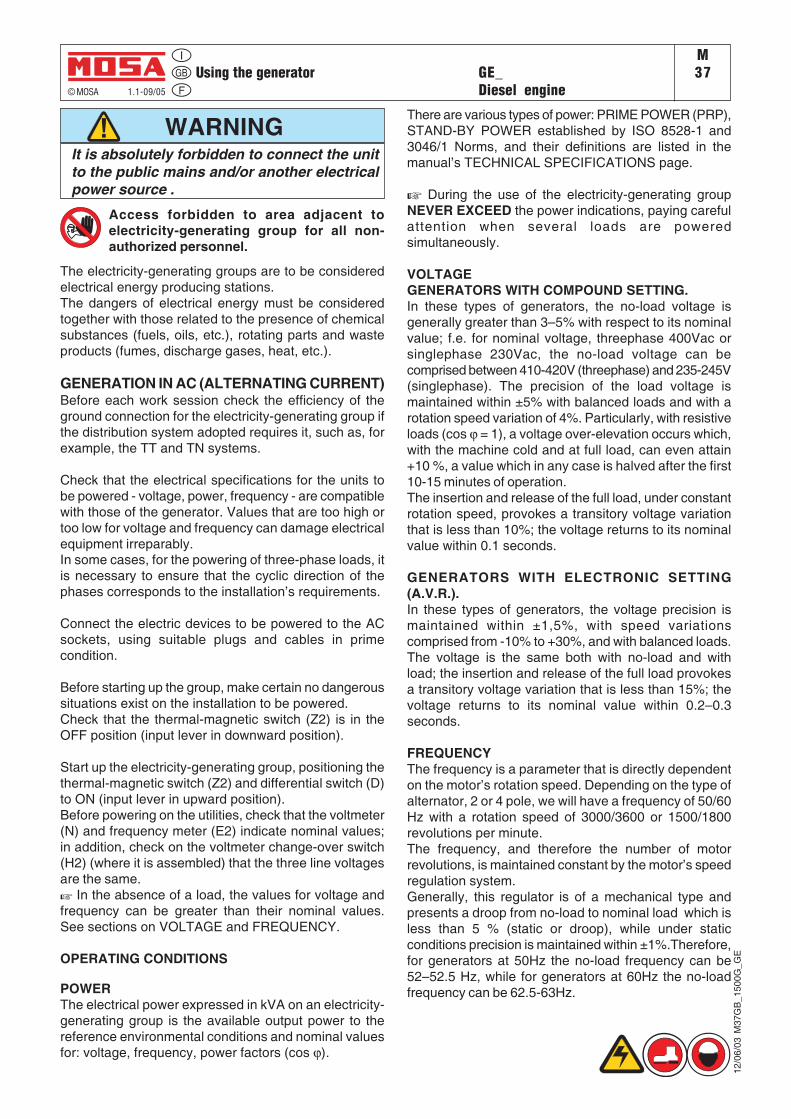
WARNING
Access forbidden to area adjacent toelectricity-generating group for all non-authorized personnel.
It is absolutely forbidden to connect the unitto the public mains and/or another electricalpower source .
GE_Diesel engine
The electricity-generating groups are to be consideredelectrical energy producing stations.The dangers of electrical energy must be consideredtogether with those related to the presence of chemicalsubstances (fuels, oils, etc.), rotating parts and wasteproducts (fumes, discharge gases, heat, etc.).
GENERATION IN AC (ALTERNATING CURRENT)Before each work session check the efficiency of theground connection for the electricity-generating group ifthe distribution system adopted requires it, such as, forexample, the TT and TN systems.
Check that the electrical specifications for the units tobe powered - voltage, power, frequency - are compatiblewith those of the generator. Values that are too high ortoo low for voltage and frequency can damage electricalequipment irreparably.In some cases, for the powering of three-phase loads, itis necessary to ensure that the cyclic direction of thephases corresponds to the installation’s requirements.
Connect the electric devices to be powered to the ACsockets, using suitable plugs and cables in primecondition.
Before starting up the group, make certain no dangeroussituations exist on the installation to be powered.Check that the thermal-magnetic switch (Z2) is in theOFF position (input lever in downward position).
Start up the electricity-generating group, positioning thethermal-magnetic switch (Z2) and differential switch (D)to ON (input lever in upward position).Before powering on the utilities, check that the voltmeter(N) and frequency meter (E2) indicate nominal values;in addition, check on the voltmeter change-over switch(H2) (where it is assembled) that the three line voltagesare the same.☞ In the absence of a load, the values for voltage andfrequency can be greater than their nominal values.See sections on VOLTAGE and FREQUENCY.
OPERATING CONDITIONS
POWERThe electrical power expressed in kVA on an electricity-generating group is the available output power to thereference environmental conditions and nominal valuesfor: voltage, frequency, power factors (cos ϕ).
There are various types of power: PRIME POWER (PRP),STAND-BY POWER established by ISO 8528-1 and3046/1 Norms, and their definitions are listed in themanual’s TECHNICAL SPECIFICATIONS page.
☞ During the use of the electricity-generating groupNEVER EXCEED the power indications, paying carefulattention when several loads are poweredsimultaneously.
VOLTAGEGENERATORS WITH COMPOUND SETTING.In these types of generators, the no-load voltage isgenerally greater than 3–5% with respect to its nominalvalue; f.e. for nominal voltage, threephase 400Vac orsinglephase 230Vac, the no-load voltage can becomprised between 410-420V (threephase) and 235-245V(singlephase). The precision of the load voltage ismaintained within ±5% with balanced loads and with arotation speed variation of 4%. Particularly, with resistiveloads (cos ϕ = 1), a voltage over-elevation occurs which,with the machine cold and at full load, can even attain+10 %, a value which in any case is halved after the first10-15 minutes of operation.The insertion and release of the full load, under constantrotation speed, provokes a transitory voltage variationthat is less than 10%; the voltage returns to its nominalvalue within 0.1 seconds.
GENERATORS WITH ELECTRONIC SETTING(A.V.R.).In these types of generators, the voltage precision ismaintained within ±1,5%, with speed variationscomprised from -10% to +30%, and with balanced loads.The voltage is the same both with no-load and withload; the insertion and release of the full load provokesa transitory voltage variation that is less than 15%; thevoltage returns to its nominal value within 0.2–0.3seconds.
FREQUENCYThe frequency is a parameter that is directly dependenton the motor’s rotation speed. Depending on the type ofalternator, 2 or 4 pole, we will have a frequency of 50/60Hz with a rotation speed of 3000/3600 or 1500/1800revolutions per minute.The frequency, and therefore the number of motorrevolutions, is maintained constant by the motor’s speedregulation system.Generally, this regulator is of a mechanical type andpresents a droop from no-load to nominal load which isless than 5 % (static or droop), while under staticconditions precision is maintained within ±1%.Therefore,for generators at 50Hz the no-load frequency can be52–52.5 Hz, while for generators at 60Hz the no-loadfrequency can be 62.5-63Hz.
Using the generatorM
37.1
© MOSA 1.1-09/05
GE_Diesel engine
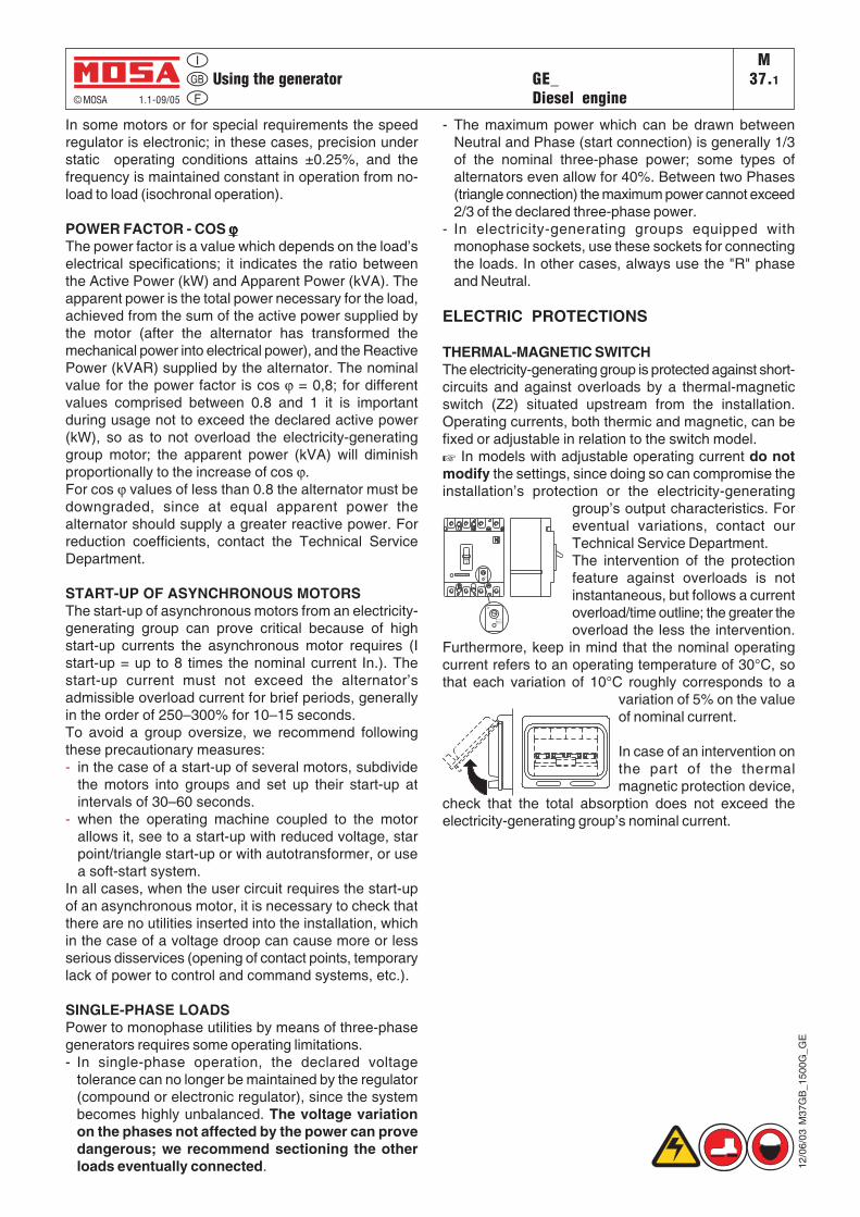
In some motors or for special requirements the speedregulator is electronic; in these cases, precision understatic operating conditions attains ±0.25%, and thefrequency is maintained constant in operation from no-load to load (isochronal operation).
POWER FACTOR - COS ϕϕϕϕϕThe power factor is a value which depends on the load’selectrical specifications; it indicates the ratio betweenthe Active Power (kW) and Apparent Power (kVA). Theapparent power is the total power necessary for the load,achieved from the sum of the active power supplied bythe motor (after the alternator has transformed themechanical power into electrical power), and the ReactivePower (kVAR) supplied by the alternator. The nominalvalue for the power factor is cos ϕ = 0,8; for differentvalues comprised between 0.8 and 1 it is importantduring usage not to exceed the declared active power(kW), so as to not overload the electricity-generatinggroup motor; the apparent power (kVA) will diminishproportionally to the increase of cos ϕ.For cos ϕ values of less than 0.8 the alternator must bedowngraded, since at equal apparent power thealternator should supply a greater reactive power. Forreduction coefficients, contact the Technical ServiceDepartment.
START-UP OF ASYNCHRONOUS MOTORSThe start-up of asynchronous motors from an electricity-generating group can prove critical because of highstart-up currents the asynchronous motor requires (Istart-up = up to 8 times the nominal current In.). Thestart-up current must not exceed the alternator’sadmissible overload current for brief periods, generallyin the order of 250–300% for 10–15 seconds.To avoid a group oversize, we recommend followingthese precautionary measures:- in the case of a start-up of several motors, subdivide
the motors into groups and set up their start-up atintervals of 30–60 seconds.
- when the operating machine coupled to the motorallows it, see to a start-up with reduced voltage, starpoint/triangle start-up or with autotransformer, or usea soft-start system.
In all cases, when the user circuit requires the start-upof an asynchronous motor, it is necessary to check thatthere are no utilities inserted into the installation, whichin the case of a voltage droop can cause more or lessserious disservices (opening of contact points, temporarylack of power to control and command systems, etc.).
SINGLE-PHASE LOADSPower to monophase utilities by means of three-phasegenerators requires some operating limitations.- In single-phase operation, the declared voltage
tolerance can no longer be maintained by the regulator(compound or electronic regulator), since the systembecomes highly unbalanced. The voltage variationon the phases not affected by the power can provedangerous; we recommend sectioning the otherloads eventually connected. 12
/06/
03 M
37G
B_1
500G
_GE
- The maximum power which can be drawn betweenNeutral and Phase (start connection) is generally 1/3of the nominal three-phase power; some types ofalternators even allow for 40%. Between two Phases(triangle connection) the maximum power cannot exceed2/3 of the declared three-phase power.
- In electricity-generating groups equipped withmonophase sockets, use these sockets for connectingthe loads. In other cases, always use the "R" phaseand Neutral.
ELECTRIC PROTECTIONS
THERMAL-MAGNETIC SWITCHThe electricity-generating group is protected against short-circuits and against overloads by a thermal-magneticswitch (Z2) situated upstream from the installation.Operating currents, both thermic and magnetic, can befixed or adjustable in relation to the switch model.☞ In models with adjustable operating current do notmodify the settings, since doing so can compromise theinstallation’s protection or the electricity-generating
group’s output characteristics. Foreventual variations, contact ourTechnical Service Department.The intervention of the protectionfeature against overloads is notinstantaneous, but follows a currentoverload/time outline; the greater theoverload the less the intervention.
Furthermore, keep in mind that the nominal operatingcurrent refers to an operating temperature of 30°C, sothat each variation of 10°C roughly corresponds to a
variation of 5% on the valueof nominal current.
In case of an intervention onthe part of the thermalmagnetic protection device,
check that the total absorption does not exceed theelectricity-generating group’s nominal current.
Using the generatorM
37.2
© MOSA 1.1-09/05
GE_Diesel engine
12/0
6/03
M37
GB
_150
0G_G
E
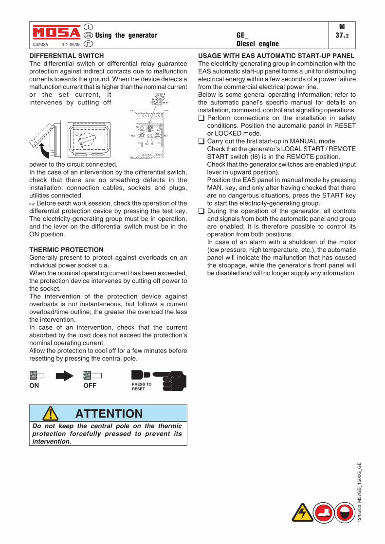
DIFFERENTIAL SWITCHThe differential switch or differential relay guaranteeprotection against indirect contacts due to malfunctioncurrents towards the ground. When the device detects amalfunction current that is higher than the nominal currentor the set current, itintervenes by cutting off
power to the circuit connected.In the case of an intervention by the differential switch,check that there are no sheathing defects in theinstallation: connection cables, sockets and plugs,utilities connected.☞ Before each work session, check the operation of thedifferential protection device by pressing the test key.The electricity-generating group must be in operation,and the lever on the differential switch must be in theON position.
THERMIC PROTECTIONGenerally present to protect against overloads on anindividual power socket c.a.When the nominal operating current has been exceeded,the protection device intervenes by cutting off power tothe socket.The intervention of the protection device againstoverloads is not instantaneous, but follows a currentoverload/time outline; the greater the overload the lessthe intervention.In case of an intervention, check that the currentabsorbed by the load does not exceed the protection’snominal operating current.Allow the protection to cool off for a few minutes beforeresetting by pressing the central pole.
ON OFF PRESS TORESET
Do not keep the central pole on the thermicprotection forcefully pressed to prevent itsintervention.
ATTENTION
USAGE WITH EAS AUTOMATIC START-UP PANELThe electricity-generating group in combination with theEAS automatic start-up panel forms a unit for distributingelectrical energy within a few seconds of a power failurefrom the commercial electrical power line.Below is some general operating information; refer tothe automatic panel’s specific manual for details oninstallation, command, control and signalling operations.
Perform connections on the installation in safetyconditions. Position the automatic panel in RESETor LOCKED mode.Carry out the first start-up in MANUAL mode.Check that the generator’s LOCAL START / REMOTESTART switch (I6) is in the REMOTE position.Check that the generator switches are enabled (inputlever in upward position).Position the EAS panel in manual mode by pressingMAN. key, and only after having checked that thereare no dangerous situations, press the START keyto start the electricity-generating group.During the operation of the generator, all controlsand signals from both the automatic panel and groupare enabled; it is therefore possible to control itsoperation from both positions.In case of an alarm with a shutdown of the motor(low pressure, high temperature, etc.), the automaticpanel will indicate the malfunction that has causedthe stoppage, while the generator’s front panel willbe disabled and will no longer supply any information.
T5.4
T5.1
T5.3
T5.2
T5.10
T5.6 T5.7
T5.8
T5.9
TRIPON
TESTRESET
0.25 2.5
20.5
1.51
0.02
0.1
0.2
0.5
0.3
0.4
RESET
I° (A) t (s)
RESETA M
tx10 tx1x1x10
x0.1I°I°
x10
tx10x1
I°
Mtx1
x0.1I°
A
1 c 0
1 d 0
1 b 0
1 a 0
T5.5
TCM 22 - 40 REMOTE CONTROLM
38.5.1
© MOSA 1.1-02/03
➔ When the TCM 22-40 is used, it is not possible to connect the E.A.S automatic intervention unit.➔ The selector LOCAL START/REMOTE START (I6) of the generating set must be switched on REMOTE
START.
MAKE SURE
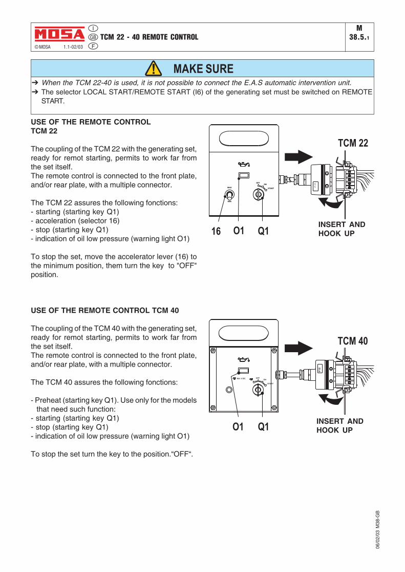
USE OF THE REMOTE CONTROLTCM 22
The coupling of the TCM 22 with the generating set,ready for remot starting, permits to work far fromthe set itself.The remote control is connected to the front plate,and/or rear plate, with a multiple connector.
The TCM 22 assures the following fonctions:- starting (starting key Q1)- acceleration (selector 16)- stop (starting key Q1)- indication of oil low pressure (warning light O1)
To stop the set, move the accelerator lever (16) tothe minimum position, them turn the key to "OFF"position.
USE OF THE REMOTE CONTROL TCM 40
The coupling of the TCM 40 with the generating set,ready for remot starting, permits to work far fromthe set itself.The remote control is connected to the front plate,and/or rear plate, with a multiple connector.
The TCM 40 assures the following fonctions:
- Preheat (starting key Q1). Use only for the modelsthat need such function:
- starting (starting key Q1)- stop (starting key Q1)- indication of oil low pressure (warning light O1)
To stop the set turn the key to the position.“OFF“.
INSERT ANDHOOK UP
INSERT ANDHOOK UP
06/0
2/03
M38
-GB
PROTECTIONS INSULATION MONITORINGM
39.10© MOSA 1.0-05/01
USE AS TROUBLE INDICATOR:Placed on the front panel, the insulation monitor(A3) is a relay which controls continuously theinsulation of the generation a.c. circuits towards theground.
The device generates internally a continuous 12Vvoltage which is applied between the circuit undercontrol and the ground.
USE AS TROUBLE INDICATOR ANDINTERVENTION:The insulation monitor controls a device (releasecoil, contactor, etc.) which opens the whole circuit,lifting voltage in the whole part of the machine a.c.generation.
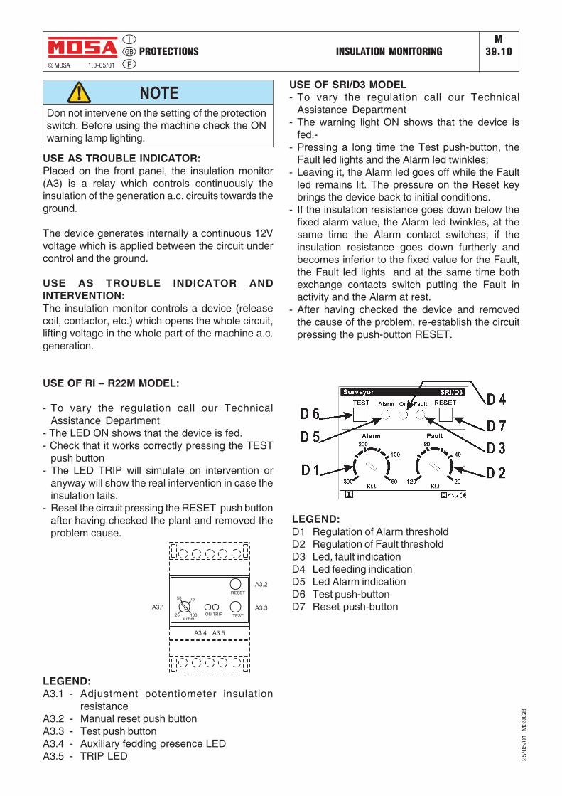
USE OF RI – R22M MODEL:
- To vary the regulation call our TechnicalAssistance Department
- The LED ON shows that the device is fed.- Check that it works correctly pressing the TEST
push button- The LED TRIP will simulate on intervention or
anyway will show the real intervention in case theinsulation fails.
- Reset the circuit pressing the RESET push buttonafter having checked the plant and removed theproblem cause.
Don not intervene on the setting of the protectionswitch. Before using the machine check the ONwarning lamp lighting.
NOTE
LEGEND:A3.1 - Adjustment potentiometer insulation
resistanceA3.2 - Manual reset push buttonA3.3 - Test push buttonA3.4 - Auxiliary fedding presence LEDA3.5 - TRIP LED
A3.2
A3.3A3.1
A3.5A3.4
RESET
TESTON TRIP25
50 75
100k ohm
USE OF SRI/D3 MODEL- To vary the regulation call our Technical
Assistance Department- The warning light ON shows that the device is
fed.-- Pressing a long time the Test push-button, the
Fault led lights and the Alarm led twinkles;- Leaving it, the Alarm led goes off while the Fault
led remains lit. The pressure on the Reset keybrings the device back to initial conditions.
- If the insulation resistance goes down below thefixed alarm value, the Alarm led twinkles, at thesame time the Alarm contact switches; if theinsulation resistance goes down furtherly andbecomes inferior to the fixed value for the Fault,the Fault led lights and at the same time bothexchange contacts switch putting the Fault inactivity and the Alarm at rest.
- After having checked the device and removedthe cause of the problem, re-establish the circuitpressing the push-button RESET.
LEGEND:D1 Regulation of Alarm thresholdD2 Regulation of Fault thresholdD3 Led, fault indicationD4 Led feeding indicationD5 Led Alarm indicationD6 Test push-buttonD7 Reset push-button
25/0
5/01
M39
GB
ENGINE PROTECTION USE EARTH LEAKAGE RELAYM
39.11© MOSA 1.1-10/05
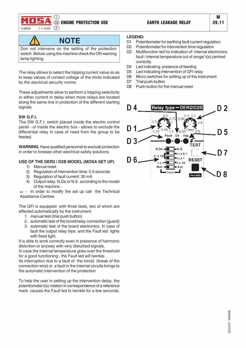
Don not intervene on the setting of the protectionswitch. Before using the machine check the ON warninglamp lighting.
NOTE
The relay allows to select the tripping current value so asto keep values of contact voltage of the limits indicatedby the electrical security norms.
These adjustments allow to perform a tripping selecticityor either current or delay when more relays are locatedalong the same line in protection of the different startingsignals.
SW G.F.I.The SW G.F.I. switch placed inside the electric controlpanel - or inside the electric box - allows to exclude thedifferential relay in case of need from the group to befeeded.
WARNING: Have qualified personnel to exclude protectionin order to foresee other electrical safety solutions.
USE OF THE DER2 / D2B MODEL (MOSA SET UP)1) Manual reset2) Regulation of intervention time: 0.5 seconds3) Regulation of fault current: 30 mA4) Output relay: N.De or N.E. according to the model
of the machine .☞ - In order to modify the set up call the TechnicalAssistance Centres
The GFI is equipped with three tests, two of which areeffected automatically by the instrument.
1. manual test (trial push button)2. automatic test of the toroid/relay connection (guard)3. automatic test of the board electronics. In case of
fault the output relay trips and the Fault led lightswith fixed light.
It is able to work correctly even in presence of harmonicdistortion or anyway with very disturbed signals.In case the internal temperature goes over the thresholdfor a good functioning , the Fault led will twinkle.Its interruption due to a fault of the toroid (break of theconnection wire) or a fault in the internal circuits brings tothe automatic intervention of the protection
To help the user in setting up the intervention delay, thepotentiometer t(s) rotation in correspondence of a referencemark causes the Fault led to twinkle for a few seconds.
25/0
5/01
M39
GB
LEGEND:D1 Potentiometer for earthing fault current regulationD2 Potentiometer for intervention time regulationD3 Multifunction led for indication of: internal electronics
fault / internal temperature out of range/ t(s) centredcorrectly.
D4 Led indicating presence of feedingD5 Led indicating intervention of GFI relayD6 Micro-switches for setting up of the instrumentD7 Trial push-buttonD8 Push-button for the manual reset
PROTECTIONS EP6 ENGINE PROTECTIONM
39.12.1
© MOSA 1.0-10/05
12/1
0/05
M39
GB
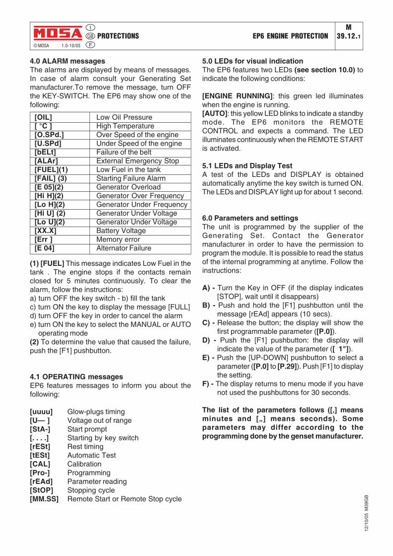
4.0 ALARM messagesThe alarms are displayed by means of messages.In case of alarm consult your Generating Setmanufacturer.To remove the message, turn OFFthe KEY-SWITCH. The EP6 may show one of thefollowing:
[OIL] Low Oil Pressure[ °C ] High Temperature[O.SPd.] Over Speed of the engine[U.SPd] Under Speed of the engine[bELt] Failure of the belt[ALAr] External Emergency Stop[FUEL](1) Low Fuel in the tank[FAIL] (3) Starting Failure Alarm[E 05](2) Generator Overload[Hi H](2) Generator Over Frequency[Lo H](2) Generator Under Frequency[Hi U] (2) Generator Under Voltage[Lo U](2) Generator Under Voltage[XX.X] Battery Voltage[Err ] Memory error[E 04] Alternator Failure
(1) [FUEL] This message indicates Low Fuel in thetank . The engine stops if the contacts remainclosed for 5 minutes continuously. To clear thealarm, follow the instructions:a) turn OFF the key switch - b) fill the tankc) turn ON the key to display the message [FULL]d) turn OFF the key in order to cancel the alarme) turn ON the key to select the MANUAL or AUTO
operating mode(2) To determine the value that caused the failure,push the [F1] pushbutton.
4.1 OPERATING messagesEP6 features messages to inform you about thefollowing:
[uuuu] Glow-plugs timing[U— ] Voltage out of range[StA-] Start prompt[. . . .] Starting by key switch[rESt] Rest timing[tESt] Automatic Test[CAL] Calibration[Pro-] Programming[rEAd] Parameter reading[StOP] Stopping cycle[MM.SS] Remote Start or Remote Stop cycle
5.0 LEDs for visual indicationThe EP6 features two LEDs (see section 10.0) toindicate the following conditions:
[ENGINE RUNNING]: this green led illuminateswhen the engine is running.[AUTO]: this yellow LED blinks to indicate a standbymode. The EP6 monitors the REMOTECONTROL and expects a command. The LEDilluminates continuously when the REMOTE STARTis activated.
5.1 LEDs and Display TestA test of the LEDs and DISPLAY is obtainedautomatically anytime the key switch is turned ON.The LEDs and DISPLAY light up for about 1 second.
6.0 Parameters and settingsThe unit is programmed by the supplier of theGenerating Set. Contact the Generatormanufacturer in order to have the permission toprogram the module. It is possible to read the statusof the internal programming at anytime. Follow theinstructions:
A) - Turn the Key in OFF (if the display indicates[STOP], wait until it disappears)
B) - Push and hold the [F1] pushbutton until themessage [rEAd] appears (10 secs).
C) - Release the button; the display will show thefirst programmable parameter ([P.0]).
D) - Push the [F1] pushbutton: the display willindicate the value of the parameter ([ 1"]).
E) - Push the [UP-DOWN] pushbutton to select aparameter ([P.0] to [P.29]). Push [F1] to displaythe setting.
F) - The display returns to menu mode if you havenot used the pushbuttons for 30 seconds.
The list of the parameters follows ([‚] meansminutes and [„] means seconds). Someparameters may differ according to theprogramming done by the genset manufacturer.
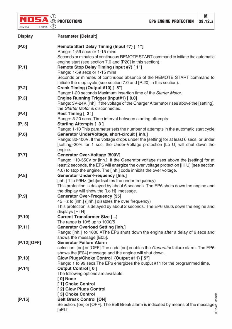
Display Parameter [Default]
[P.0] Remote Start Delay Timing (Input #7) [ 1"]Range: 1-59 secs or 1-15 minsSeconds or minutes of continuous REMOTE START command to initiate the automaticengine start (see section 7.0 and [P20] in this section).
[P.1] Remote Stop Delay Timing (Input #7) [ 1"]Range: 1-59 secs or 1-15 minsSeconds or minutes of continuous absence of the REMOTE START command toinitiate the stop cycle (see section 7.0 and [P.20] in this section).
[P.2] Crank Timing (Output #10) [ 5"]Range:1-20 seconds Maximum insertion time of the Starter Motor.
[P.3] Engine Running Trigger (Input#1) [ 8.0]Range: 3V-24V,[inh] If the voltage of the Charger Alternator rises above the [setting],the Starter Motor is disconnected.
[P.4] Rest Timing [ 3"]Range: 3-20 secs. Time interval between starting attempts
[P. 5] Starting Attempts [ 3 ]Range: 1-10 This parameter sets the number of attempts in the automatic start cycle
[P.6] Generator UnderVoltage, short-circuit [ inh.]Range: 80-400V. If the voltage drops under the [setting] for at least 6 secs, or under[setting]-20% for 1 sec, the Under-Voltage protection [Lo U] will shut down theengine.
[P.7] Generator Over-Voltage [500V]Range: 110-550V or [inh.]. If the Generator voltage rises above the [setting] for atleast 2 seconds, the EP6 will energize the over voltage protection [Hi U] (see section4.0) to stop the engine. The [inh.] code inhibits the over voltage.
[P.8] Generator Under-Frequency [Inh.][inh.] 1 to 99Hz ([inh]=disables the under frequency)This protection is delayed by about 6 seconds. The EP6 shuts down the engine andthe display will show the [Lo H] message.
[P.9] Generator Over-Frequency [55]45 Hz to [inh.] ([inh.] disables the over frequency)This protection is delayed by about 2 seconds. The EP6 shuts down the engine anddisplays [Hi H]
[P.10] Current Transformer Size [...]The range is 10/5 up to 1000/5
[P.11] Generator Overload Setting [inh.]Range: [inh.] to 1000 AThe EP6 shuts down the engine after a delay of 6 secs andshows the message [E05].
[P.12][OFF] Generator Failure Alarmselection: [on] or [OFF].The code [on] enables the Generator failure alarm. The EP6shows the [E04] message and the engine will shut down.
[P.13] Glow Plugs/Choke Control (Output #11) [ 5"]Range: 1 to 99 secs.The EP6 energizes the output #11 for the programmed time.
[P.14] Output Control [ 0 ]The following options are available:[ 0] None[ 1] Choke Control[ 2] Glow Plugs Control[ 3] Choke Control
[P.15] Belt Break Control [ON]Selection: [on] or [OFF]. The Belt Break alarm is indicated by means of the message[bELt]
PROTECTIONS EP6 ENGINE PROTECTIONM
39.12.2
© MOSA 1.0-10/05
12/1
0/05
M39
GB
PROTECTIONS EP6 ENGINE PROTECTIONM
39.12© MOSA 1.0-10/05
12/1
0/05
M39
GB
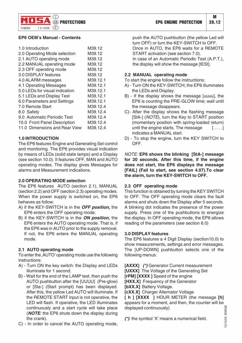
EP6 OEM’s Manual - Contents
1.0 Introduction M39.122.0 Operating Mode selection M39.122.1 AUTO operating mode M39.122.2 MANUAL operating mode M39.122.3 OFF operating mode M39.123.0 DISPLAY features M39.124.0 ALARM messages M39.12.14.1 Operating Messages M39.12.15.0 LEDs for visual indication M39.12.15.1 LEDs and Display Test M39.12.16.0 Parameters and Settings M39.12.17.0 Remote Start M39.12.48.0 Safety M39.12.49.0 Automatic Periodic Test M39.12.410.0 Front Panel Description M39.12.411.0 Dimensions and Rear View M39.12.4
1.0 INTRODUCTIONThe EP6 features Engine and Generating Set controland monitoring. The EP6 provides visual indicationby means of LEDs (solid state lamps) and a Display(see section 10.0). It features OFF, MAN and AUTOoperating modes. The display gives Messages foralarms and Measurement indications.
2.0 OPERATING MODE selectionThe EP6 features AUTO (section 2.1), MANUAL(section 2.2) and OFF (section 2.3) operating modes.When the power supply is switched on, the EP6behaves as follow:A) if the KEY-SWITCH is in the OFF position, the
EP6 enters the OFF operating mode.B) if the KEY-SWITCH is in the ON position, the
EP6 enters the AUTO operating mode. That is, ifthe EP6 was in AUTO prior to the supply removal.If not, the EP6 enters the MANUAL operatingmode.
2.1 AUTO operating modeTo enter the ‚AUTO‘ operating mode use the followinginstructions:A) - Turn ON the key switch: the Display and LEDs
illuminate for 1 second.B) - Wait for the end of the LAMP test, then push the
AUTO pushbutton after the [UUUU] (Pre-glow)or [Sta-] (Start prompt) has been displayed.After this, the yellow Led AUTO will illuminate. Ifthe REMOTE START input is not operative, theLED will flash. If operative, the LED illuminatescontinuously and a start cycle will take place(NOTE: the EP6 shuts down the display duringthe crank).
C) - In order to cancel the AUTO operating mode,
push the AUTO pushbutton (the yellow Led willturn OFF) or turn the KEY-SWITCH to OFF.Once in AUTO, the EP6 waits for a REMOTESTART activation (see section 7.0).In case of an Automatic Periodic Test (A.P.T.),the display will show the message [tESt].
2.2 MANUAL operating modeTo start the engine follow the instructions:A) - Turn ON the KEY-SWITCH; the EP6 illuminates
the LEDs and Display.B) - If the display shows the message [uuuu], the
EP6 is counting the PRE-GLOW time; wait untilthe message disappears.
C)- After the display shows the flashing message[StA-] (NOTE), turn the Key to START position(momentary position with spring-loaded return)until the engine starts. The message [ . . . .]indicates a MANUAL start.
D) - To stop the engine, turn the KEY SWITCH toOFF.
NOTE: EP6 shows the blinking [StA-] messagefor 20 seconds. After this time, if the enginedoes not start, the EP6 displays the message[FAIL] (Fail to start, see section 4.07).To clearthe alarm, turn the KEY-SWITCH to OFF.
2.3 OFF operating modeThis function is obtained by turning the KEY SWITCHto OFF. The OFF operating mode clears the faultalarms and shuts down the Display after 5 seconds.A blinking dot indicates the presence of the powersupply. Press one of the pushbuttons to energizethe display. In OFF operating mode, the EP6 allowsreading of the parameters (see section 6.0)
3.0 DISPLAY featuresThe EP6 features a 4 Digit Display (section10.0) toshow measurements, settings and error messages.The [UP-DOWN] pushbutton selects one of thefollowing menus:
[AXXX] (*) Generator Current measurement[UXXX] The Voltage of the Generating Set[rPM] [XXXX ] Speed of the engine[HXX.X] Frequency of the Generator[bXX.X] Battery Voltage.[cXX.X] Charger Alternator Voltage[ h ] [XXXX ] HOUR METER (the message [h]appears for a moment, and then, the counter will bedisplayed continuously)
(*): the symbol ‘X’ means a numerical field.
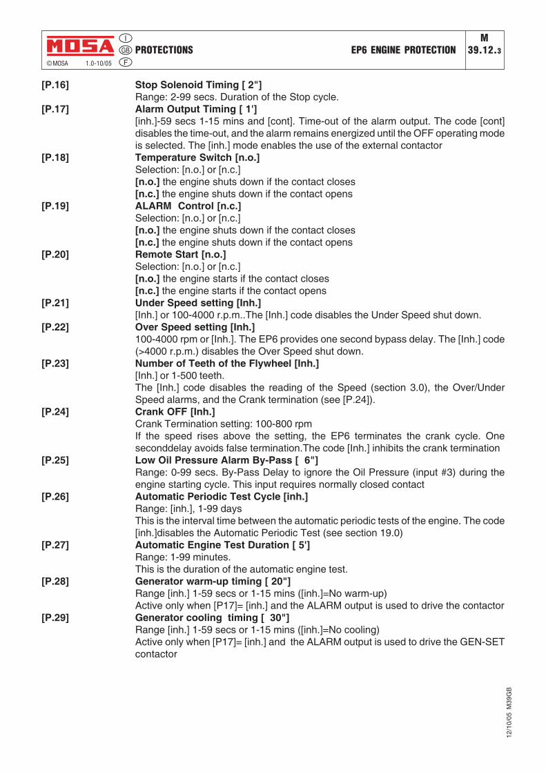
[P.16] Stop Solenoid Timing [ 2"]Range: 2-99 secs. Duration of the Stop cycle.
[P.17] Alarm Output Timing [ 1'][inh.]-59 secs 1-15 mins and [cont]. Time-out of the alarm output. The code [cont]disables the time-out, and the alarm remains energized until the OFF operating modeis selected. The [inh.] mode enables the use of the external contactor
[P.18] Temperature Switch [n.o.]Selection: [n.o.] or [n.c.][n.o.] the engine shuts down if the contact closes[n.c.] the engine shuts down if the contact opens
[P.19] ALARM Control [n.c.]Selection: [n.o.] or [n.c.][n.o.] the engine shuts down if the contact closes[n.c.] the engine shuts down if the contact opens
[P.20] Remote Start [n.o.]Selection: [n.o.] or [n.c.][n.o.] the engine starts if the contact closes[n.c.] the engine starts if the contact opens
[P.21] Under Speed setting [Inh.][Inh.] or 100-4000 r.p.m..The [Inh.] code disables the Under Speed shut down.
[P.22] Over Speed setting [Inh.]100-4000 rpm or [Inh.]. The EP6 provides one second bypass delay. The [Inh.] code(>4000 r.p.m.) disables the Over Speed shut down.
[P.23] Number of Teeth of the Flywheel [Inh.][Inh.] or 1-500 teeth.The [Inh.] code disables the reading of the Speed (section 3.0), the Over/UnderSpeed alarms, and the Crank termination (see [P.24]).
[P.24] Crank OFF [Inh.]Crank Termination setting: 100-800 rpmIf the speed rises above the setting, the EP6 terminates the crank cycle. Oneseconddelay avoids false termination.The code [Inh.] inhibits the crank termination
[P.25] Low Oil Pressure Alarm By-Pass [ 6"]Range: 0-99 secs. By-Pass Delay to ignore the Oil Pressure (input #3) during theengine starting cycle. This input requires normally closed contact
[P.26] Automatic Periodic Test Cycle [inh.]Range: [inh.], 1-99 daysThis is the interval time between the automatic periodic tests of the engine. The code[inh.]disables the Automatic Periodic Test (see section 19.0)
[P.27] Automatic Engine Test Duration [ 5']Range: 1-99 minutes.This is the duration of the automatic engine test.
[P.28] Generator warm-up timing [ 20"]Range [inh.] 1-59 secs or 1-15 mins ([inh.]=No warm-up)Active only when [P17]= [inh.] and the ALARM output is used to drive the contactor
[P.29] Generator cooling timing [ 30"]Range [inh.] 1-59 secs or 1-15 mins ([inh.]=No cooling)Active only when [P17]= [inh.] and the ALARM output is used to drive the GEN-SETcontactor
PROTECTIONS EP6 ENGINE PROTECTIONM
39.12.3
© MOSA 1.0-10/05
12/1
0/05
M39
GB

7.0 REMOTE STARTThe EP6 features REMOTE START only in AUTOoperating mode.To operate the REMOTE START, follow theinstructions.
A) - Turn the KEY-SWITCH to the ON position; theDisplay and LEDs illuminate for 1 sec.
B) - Wait until the end of the LEDs test.C) - Push the AUTO pushbutton as soon as possible
(otherwise, after 20 seconds the EP6 entersthe STARTING FAILURE); the [AUTO] yellowLED will illuminate as described in the nextsection
7.1 - REMOTE START SWITCH:If the REMOTE START input is activated, the[AUTO] yellow LED illuminates continuously andthe display will indicate the count down of the internalstart delay timer by means of the message [MM.SS](Minutes and seconds). The engine will start afterthe programmed start delay time. If the REMOTESTART is deactivated, the EP6 drives the stopdelay time. The display will indicate the count downby means of the message [MM.SS] (Minutes andseconds), and the [AUTO] yellow LED will flash.The engine will stop after the programmed stopdelay time.
Note start delay time: see section 6.0 parameter[P.0]
Note stop delay time: see section 6.0 parameter[P.1]
8.0 SAFETY
Test, we recommend the following procedures.- disconnect the power supply of the EP6 (consultyour genset supplier)
- wait for the desired start time (external clockreference)
- apply the power supply to the EP6 (consult yourgenset supplier)
- select the ‚AUTO‘ operating modeThe EP6 will start the engine after the programmednumber of days and the engine will run for theprogrammed time. To determine how the AutomaticPeriodic Test is programmed enter the ReadingMode (section 6.0 parameter [P.26] and [P.27]).
IMPORTANT NOTESIf the supply (battery voltage) is removed, theEP6 loses the counts and timings. If the supplyrestores, the EP6 starts to count the A.P.T.according to the programmed parameters [P.26]and [P.27]. It is important to synchronize thepower on sequence with the desired AutomaticPeriodic Test.
10.0 FRONT PANEL
High voltage is present inside the EP6. To avoidelectric-shock hazard, operating personnel mustnot remove the protective cover. Do notdisconnect the grounding connection. Anyinterruption of the grounding connection can cre-ate an electric shock hazard. Before makingexternal connections, always ground the PANELfirst by connecting the control panel to ground.
NOTE
9.0 Automatic periodic TEST
The EP6 does not use a clock to count theprogrammed days ([P.26] setting, section 6.0). Themaximum error and drift of the counter is +/-0,5%.The user may experiment with shifting the periodictests. To avoid error accumulation, and in caseyour unit is programmed to allow Automatic Periodic
PROTECTIONS EP6 ENGINE PROTECTIONM
39.12.4
© MOSA 1.0-10/05
12/1
0/05
M39
GB
4 digits DISPLAY
Ideograms
Button[F1]
Button[ENTER] (*)
Key(OFF-ON-START)
Button [+](*)
Button [-] (*)
Button[AUTO]
AUTO (YellowLed)
[UP DOWN]Button
Green LEDengine on
Front view
Closingcover
Cables outlet
Rear viewRecommended hole dimensions:
91mm (+/- 0.5) x 91mm (+/- 0.5)
Rear cover
(*) The use of these buttons isreserved only to the manufacturerof the generating set.
11.0 DIMENSIONS
TroubleshootingM
40.2© MOSA REV.3-07/06
28/0
1/03
M40
I_15
00G
_GE
GEDiesel engine
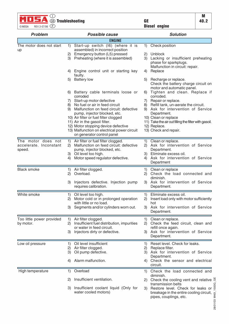
The motor does not startup
1) Start-up switch (I6) (where it isassembled) in incorrect position
2) Emergency button (L5) pressed3) Preheating (where it is assembled)
4) Engine control unit or starting keyfaulty.
5) Battery low
6) Battery cable terminals loose orcorroded
7) Start-up motor defective8) No fuel or air in feed circuit9) Malfunction on feed circuit: defective
pump, injector blocked, etc.10) Air filter or fuel filter clogged11) Air in the gasoil filter.12) Motor stopping device defective13) Malfunction on electrical power circuit
on generator control panel
1) Check position
2) Unblock3) Lacking or insufficient preheating
phase for sparkplugs.Malfunction in circuit: repair.
4) Replace
5) Recharge or replace.Check the battery charge circuit onmotor and automatic panel.
6) Tighten and clean. Replace ifcorroded.
7) Repair or replace.8) Refill tank, un-aerate the circuit.9) Ask for intervention of Service
Department.10) Clean or replace11) Take the air out filling the filter with gasoil.12) Replace.13) Check and repair.
Problem Possible cause Solution
The motor does notaccelerate. Inconstantspeed.
1) Air filter or fuel filter clogged.2) Malfunction on feed circuit: defective
pump, injector blocked, etc.3) Oil level too high.4) Motor speed regulator defective.
1) Clean or replace.2) Ask for intervention of Service
Department.3) Eliminate excess oil.4) Ask for intervention of Service
Department
Black smoke 1) Air filter clogged.2) Overload.
3) Injectors defective. Injection pumprequires calibration.
1) Clean or replace2) Check the load connected and
diminish.3) Ask for intervention of Service
Department.
White smoke 1) Oil level too high.2) Motor cold or in prolonged operation
with little or no load.3) Segments and/or cylinders worn out.
1) Eliminate excess oil.2) Insert load only with motor sufficiently
hot3) Ask for intervention of Service
Department.
Too little power providedby motor.
1) Air filter clogged.2) Insufficient fuel distribution, impurities
or water in feed circuit.3) Injectors dirty or defective.
1) Clean or replace.2) Check the feed circuit, clean and
refill once again.3) Ask for intervention of Service
Department.
Low oil pressure 1) Oil level insufficient2) Air filter clogged.3) Oil pump defective.
4) Alarm malfunction.
1) Reset level. Check for leaks.2) Replace filter.3) Ask for intervention of Service
Department.4) Check the sensor and electrical
circuit.
High temperature 1) Overload
2) Insufficient ventilation.
3) Insufficient coolant liquid (Only forwater cooled motors)
1) Check the load connected anddiminish.
2) Check the cooling vent and relativetransmission belts
3) Restore level. Check for leaks orbreakage in the entire cooling circuit,pipes, couplings, etc.
ENGINE
TroubleshootingM
40.2.1
© MOSA REV.3-07/06
12/0
6/03
M40
GB
_150
0G_G
E
GEDiesel engine
Problem Possible cause Solution
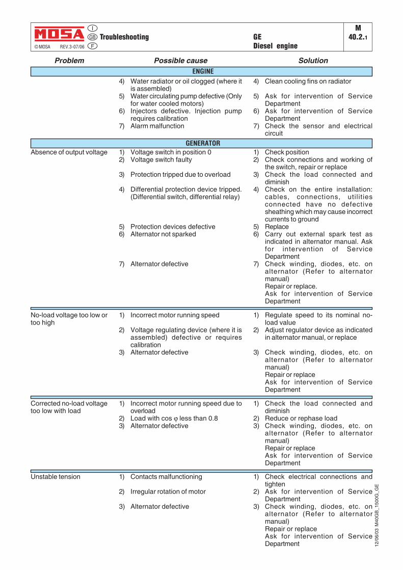
4) Water radiator or oil clogged (where itis assembled)
5) Water circulating pump defective (Onlyfor water cooled motors)
6) Injectors defective. Injection pumprequires calibration
7) Alarm malfunction
4) Clean cooling fins on radiator
5) Ask for intervention of ServiceDepartment
6) Ask for intervention of ServiceDepartment
7) Check the sensor and electricalcircuit
Absence of output voltage 1) Voltage switch in position 02) Voltage switch faulty
3) Protection tripped due to overload
4) Differential protection device tripped.(Differential switch, differential relay)
5) Protection devices defective6) Alternator not sparked
7) Alternator defective
1) Check position2) Check connections and working of
the switch, repair or replace3) Check the load connected and
diminish4) Check on the entire installation:
cables, connections, util it iesconnected have no defectivesheathing which may cause incorrectcurrents to ground
5) Replace6) Carry out external spark test as
indicated in alternator manual. Askfor intervention of ServiceDepartment
7) Check winding, diodes, etc. onalternator (Refer to alternatormanual)Repair or replace.Ask for intervention of ServiceDepartment
No-load voltage too low ortoo high
1) Incorrect motor running speed
2) Voltage regulating device (where it isassembled) defective or requirescalibration
3) Alternator defective
1) Regulate speed to its nominal no-load value
2) Adjust regulator device as indicatedin alternator manual, or replace
3) Check winding, diodes, etc. onalternator (Refer to alternatormanual)Repair or replaceAsk for intervention of ServiceDepartment
Corrected no-load voltagetoo low with load
1) Check the load connected anddiminish
2) Reduce or rephase load3) Check winding, diodes, etc. on
alternator (Refer to alternatormanual)Repair or replaceAsk for intervention of ServiceDepartment
1) Check electrical connections andtighten
2) Ask for intervention of ServiceDepartment
3) Check winding, diodes, etc. onalternator (Refer to alternatormanual)Repair or replaceAsk for intervention of ServiceDepartment
1) Incorrect motor running speed due tooverload
2) Load with cos ϕ less than 0.83) Alternator defective
1) Contacts malfunctioning
2) Irregular rotation of motor
3) Alternator defective
Unstable tension
ENGINE
GENERATOR
MAINTENANCEM43
© MOSA 1.0-09/05
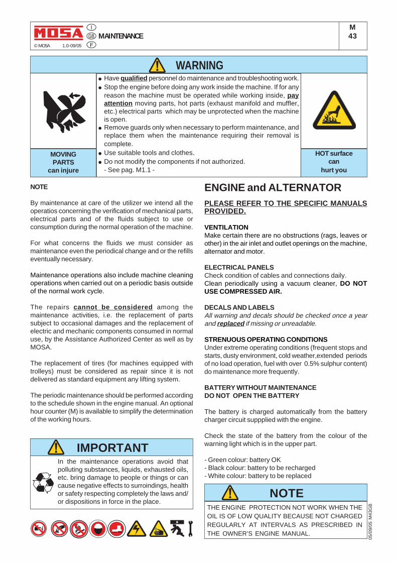
NOTE
By maintenance at care of the utilizer we intend all theoperatios concerning the verification of mechanical parts,electrical parts and of the fluids subject to use orconsumption during the normal operation of the machine.
For what concerns the fluids we must consider asmaintenance even the periodical change and or the refillseventually necessary.
Maintenance operations also include machine cleaningoperations when carried out on a periodic basis outsideof the normal work cycle.
The repairs cannot be considered among themaintenance activities, i.e. the replacement of partssubject to occasional damages and the replacement ofelectric and mechanic components consumed in normaluse, by the Assistance Authorized Center as well as byMOSA.
The replacement of tires (for machines equipped withtrolleys) must be considered as repair since it is notdelivered as standard equipment any lifting system.
The periodic maintenance should be performed accordingto the schedule shown in the engine manual. An optionalhour counter (M) is available to simplify the determinationof the working hours.
THE ENGINE PROTECTION NOT WORK WHEN THEOIL IS OF LOW QUALITY BECAUSE NOT CHARGEDREGULARLY AT INTERVALS AS PRESCRIBED INTHE OWNER’S ENGINE MANUAL.
NOTE
IMPORTANTIn the maintenance operations avoid thatpolluting substances, liquids, exhausted oils,etc. bring damage to people or things or cancause negative effects to surroindings, healthor safety respecting completely the laws and/or dispositions in force in the place.
WARNING● Have qualified personnel do maintenance and troubleshooting work.● Stop the engine before doing any work inside the machine. If for any
reason the machine must be operated while working inside, payattention moving parts, hot parts (exhaust manifold and muffler,etc.) electrical parts which may be unprotected when the machineis open.
● Remove guards only when necessary to perform maintenance, andreplace them when the maintenance requiring their removal iscomplete.
● Use suitable tools and clothes.● Do not modify the components if not authorized.
- See pag. M1.1 -
HOT surfacecan
hurt you
MOVINGPARTS
can injure
05/0
9/05
M43
GB
ENGINE and ALTERNATORPLEASE REFER TO THE SPECIFIC MANUALSPROVIDED.
VENTILATIONMake certain there are no obstructions (rags, leaves orother) in the air inlet and outlet openings on the machine,alternator and motor.
ELECTRICAL PANELSCheck condition of cables and connections daily.Clean periodically using a vacuum cleaner, DO NOTUSE COMPRESSED AIR.
DECALS AND LABELSAll warning and decals should be checked once a yearand replaced if missing or unreadable.
STRENUOUS OPERATING CONDITIONSUnder extreme operating conditions (frequent stops andstarts, dusty environment, cold weather,extended periodsof no load operation, fuel with over 0.5% sulphur content)do maintenance more frequently.
BATTERY WITHOUT MAINTENANCEDO NOT OPEN THE BATTERY
The battery is charged automatically from the batterycharger circuit suppplied with the engine.
Check the state of the battery from the colour of thewarning light which is in the upper part.
- Green colour: battery OK- Black colour: battery to be recharged- White colour: battery to be replaced
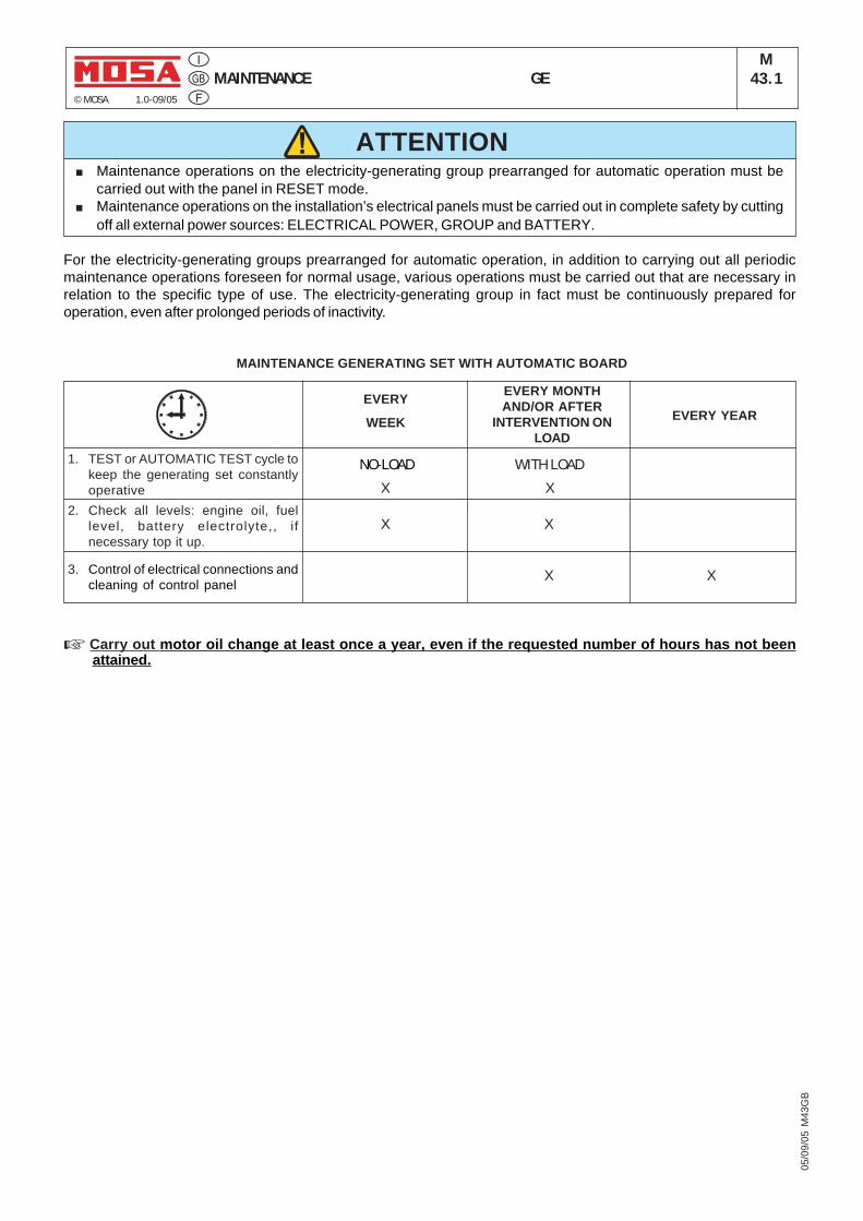
MAINTENANCE GEM
43.1© MOSA 1.0-09/05
05/0
9/05
M43
GB
ATTENTION■ Maintenance operations on the electricity-generating group prearranged for automatic operation must be
carried out with the panel in RESET mode.■ Maintenance operations on the installation’s electrical panels must be carried out in complete safety by cutting
off all external power sources: ELECTRICAL POWER, GROUP and BATTERY.
EVERY MONTHAND/OR AFTER
INTERVENTION ONLOAD
EVERY YEAR
1. TEST or AUTOMATIC TEST cycle tokeep the generating set constantlyoperative
2. Check all levels: engine oil, fuellevel, battery electrolyte,, ifnecessary top it up.
3. Control of electrical connections andcleaning of control panel
EVERY
WEEK
NO-LOAD
X
WITH LOAD
X
X X
X X
For the electricity-generating groups prearranged for automatic operation, in addition to carrying out all periodicmaintenance operations foreseen for normal usage, various operations must be carried out that are necessary inrelation to the specific type of use. The electricity-generating group in fact must be continuously prepared foroperation, even after prolonged periods of inactivity.
MAINTENANCE GENERATING SET WITH AUTOMATIC BOARD
☞ Carry out motor oil change at least once a year, even if the requested number of hours has not beenattained.
STORAGE GE_, MS_, TS_M45
© MOSA 1.0-06/00
In case the machine should not be used for more than 30days, make sure that the room in which it is storedpresents a suitable shelter from heat sources, weatherchanges or anything which can cause rust, corrosion ordamages to the machine.
☞ Have qualified personnel prepare the machine forstorage.
GASOLINE ENGINE
Start the engine: lt will run until it stops due to the lack offuel.
Drain the oil from the engine sump and fill it with new oil(see page M25).
Pour about 10 cc of oil into the spark plug hole and screwthe spark plug, after having rotated the crankshaft severaltimes.
Rotate the crankshaft slowly until you feel a certaincompression, then leave it.
In case the battery, for the electric start, is assembled,disconnect it.
Clean the covers and all the other parts of the machinecarefully.
Protect the machine with a plastic hood and store it in odry place.
DIESEL ENGINE
For short periods of time it is advisable, about every 10days, to make the machine work with load for 15-30minutes, for a correct distribution of the lubricant, torecharge the battery and to prevent any possible blokingof the injection system.
For long periods of inactivity, turn to the after solesservice of the engine manufacturer.
Clean the covers and all the other parts of the machinecarefully.
Protect the machine with a plastic hood and store it in adry place.
In the storage operations avoid thatpolluting substances, liquids, exhaustedoils, etc. bring damage to people orthings or can cause negative effects tosurroindings, health or safety respectingcompletely the laws and/or dispositionsin force in the place.
IMPORTANT
30/0
0/00
M45
GB
In case of necessity for first aid and of fire prevention,see page. M2.5.
CUST OFF GE_, MS_, TS_M46
© MOSA 1.0-03/00
In the cust-off operations avoid thatpolluting substances, liquids, exhaustedoils, etc. bring damage to people orthings or can cause negative effects tosurroindings, health or safety respectingcompletely the laws and/or dispositionsin force in the place.
IMPORTANT
☞ Have qualified personnel disassemble themachine and dispose of the parts, including theoil, fuel, etc., in a correct manner when it is tobe taken out of service.
As cust off we intend all operations to be made, atutilizer’s care, at the end of the use of the machine.This comprises the dismantling of the machine, thesubdivision of the several components for a furtherreutilization or for getting rid of them, the eventualpacking and transportation of the eliminated partsup to their delivery to the store, or to the bureauencharged to the cust off or to the storage office,etc.
The several operations concerning the cust off,involve the manipulation of fluids potentiallydangerous such as: lubricating oil and batteryelectrolyte.
The dismantling of metallic parts liable to causeinjuries or wounds, must be made wearing heavygloves and using suitable tools.
The getting rid of the various components of themachine must be made accordingly to rules in forceof law a/o local rules.Particular attention must be paid when gettingrid of:lubricating oils, battery electrolyte, andinflamable liquids such as fuel, cooling liquid.
The machine user is responsible for the observanceof the norms concerning the environment conditionswith regard to the elimination of the machine beingcust off and of all its components.
In case the machine should be cust off without anyprevious disassembly it is however compulsory toremove:- tank fuel- engine lubricating oil- cooling liquid from the engine- battery
NOTE: MOSA is involved with custing off themachine only for the second hand ones, when notreparable.This, of course, after authorization.
In case of necessity for first aid and fire prevention,see page M2.5.
30/0
3/00
M45
GB
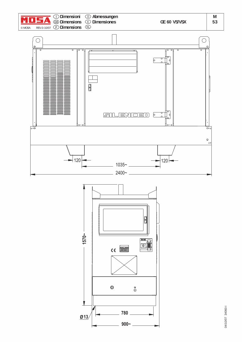
© MOSA REV.0-10/07
DimensioniDimensionsDimensions
GE 60 VS/VSXM53
AbmessungenDimensionesE
D
NL
04/1
0/07
340
60-I
Ø
E
MERGENCY
I. CL.
TYPE
SERIAL N°
RPM
Hz COS ø
IP
1570~
900~
78013
2400~
1201035~
120
ELECTRICAL SYSTEM LEGENDE GE_, MS_, TS_M60
© MOSA REV.5-09/07
26/0
7/04
M60
GB
A: AlternatorB: Wire connection unitC: CapacitorD: G.F.I.E: Welding PCB transformerF: FuseG: 400V 3-phase socketH: 230V 1phase socketI: 110V 1-phase socketL: Socket warning lightM: Hour-counterN: VoltmeterP: Welding arc regulatorQ: 230V 3-phase socketR: Welding control PCBS: Welding current ammeterT: Welding current regulatorU: Current transformerV: Welding voltage voltmeterZ: Welding socketsX: ShuntW: D.C. inductorY: Welding diode bridge
A1: Arc striking resistorB1: Arc striking circuitC1: 110V D.C./48V D.C. diode bridgeD1: E.P.1 engine protectionE1: Engine stop solenoidF1: Acceleration solenoidG1: Fuel level transmitterH1: Oil or water thermostatI1: 48V D.C. socketL1: Oil pressure switchM1: Fuel warning lightN1: Battery charge warning lightO1: Oil pressure warning lightP1: FuseQ1: Starter keyR1: Starter motorS1: BatteryT1: Battery charge alternatorU1: Battery charge voltage regulatorV1: Solenoid valve control PCBTZ1: Solenoid valveW1: Remote control switchX1: Remote control and/or wire feeder
socketY1: Remote control plug
A2: Remote control welding regulatorB2: E.P.2 engine protectionC2: Fuel level gaugeD2: AmmeterE2: Frequency meterF2: Battery charge trasformerG2: Battery charge PCBH2: Voltage selector switchI2: 48V a.c. socketL2: Thermal relayM2: ContactorN2: G.F.I. and circuit breakerO2: 42V EEC socketP2: G.F.I. resistorQ2: T.E.P. engine protectionR2: Solenoid control PCBTS2: Oil level transmitterT2: Engine stop push-button T.C.1U2: Engine start push-buttonT.C.1V2: 24V c.a. socketZ2: Thermal magnetic circuit breakerW2: S.C.R. protection unitX2: Remote control socketY2: Remote control plug
A3: Insulation moitoringB3: E.A.S. connectorC3: E.A.S. PCBD3: Booster socketE3: Open circuit voltage switchF3: Stop push-buttonG3: Ignition coilH3: Spark plugI3: Range switchL3: Oil shut-down buttonM3: Battery charge diodeN3: RelayO3: ResistorP3: Sparkler reactorQ3: Output power unitR3: Electric sirenS3: E.P.4 engine protectionT3: Engine control PCBU3: R.P.M. electronic regulatorV3: PTO HI control PCBZ3: PTO HI 20 l/min push-buttonW3: PTO HI 30 l/min push-buttonX3: PTO HI reset push-buttonY3: PTO HI 20 l/min indicator
A4: PTO HI 30 l/min indicatorB4: PTO HI reset indicatorC4: PTO HI 20 l/min solenoid valveD4: PTO HI 30 l/ min solenoid valveE4: Hydraulic oil pressure switchF4: Hycraulic oil level gaugeG4: Preheating glow plugsH4: Preheating gearboxI4: Preheating indicatorL4: R.C. filterM4: Heater with thermostatN4: Choke solenoidO4: Step relayP4: Circuit breakerQ4: Battery charge socketsR4: Sensor, cooling liquid temperatureS4: Sensor, air filter cloggingT4: Warning light, air filter cloggingU4: Polarity inverter remote controlV4: Polarity inverter switchZ4: Transformer 230/48VW4: Diode bridge, polarity changeX4: Base current diode bridgeY4: PCB control unit, polarity inverter
A5: Base current switchB5: Auxiliary push-button ON/OFFC5: Accelerator electronic controlD5: ActuatorE5: Pick-upF5: Warning light, high temperatureG5: Commutator auxiliary powerH5: 24V diode bridgeI5: Y/s commutatorL5: Emergency stop buttonM5: Engine protection EP5N5: Pre-heat push-buttonO5: Accelerator solenoid PCBP5: Oil pressure switchQ5: Water temperature switchR5: Water heaterS5: Engine connector 24 polesT5: Electronic GFI relaisU5: Release coil, circuit breakerV5: Oil pressure indicatorZ5: Water temperature indicatorW5: Battery voltmeterX5: Contactor, polarity changeY5: Commutator/switch, series/parallel
A6: Commutator/switchB6: Key switch, on/offC6: QEA control unitD6: Connector, PACE6: Frequency rpm regulatorF6: Arc-Force selectorG6: Device starting motorH6: Fuel electro pump 12V c.c.I6: Start Local/Remote selectorL6: Choke buttonM6: Switch CC/CVN6: Connector – wire feederO6: 420V/110V 3-phase transformerP6: Switch IDLE/RUNQ6: Hz/V/A analogic instrumentR6: EMC filterS6: Wire feeder supply switchT6: Wire feeder socketU6: DSP chopper PCBV6: Power chopper supply PCBZ6: Switch and leds PCBW6: Hall sensorX6: Water heather indicatorY6: Battery charge indicator
A7: Transfer pump selector AUT-0-MANB7: Fuel transfer pumpC7: „GECO“ generating set testD7: Flooting with level switchesE7: Voltmeter regulatorF7: WELD/AUX switchG7: Reactor, 3-phaseH7: Switch disconnectorI7: Solenoid stop timerL7: "VODIA" connectorM7: "F" EDC4 connectorN7: OFF-ON-DIAGN. selectorO7: DIAGNOSTIC push-buttonP7: DIAGNOSTIC indicatorQ7: Welding selector modeR7: R.C. netS7: 230V 1-phase plugT7: V/Hz analogic instrumentU7: Engine protection EP6V7: G.F.I. relay supply switchZ7: Radio remote control receiverW7: Radio remote control trasnsmitterX7: Isometer test push-buttonY7: Remote start socket
A8: Transfer fuel pump controlB8: Ammeter selector switchC8: 400V/230V/115V commutatorD8: 50/60 Hz switchE8: Cold start advance with temp. switchF8: START/STOP switchG8: Polarity inverter two way switchH8: Engine protection EP7I8: AUTOIDLE switchL8: AUTOIDLE PCBM8:N8:O8:P8:Q8:R8:S8:T8:U8:V8:Z8:W8:X8:Y8:
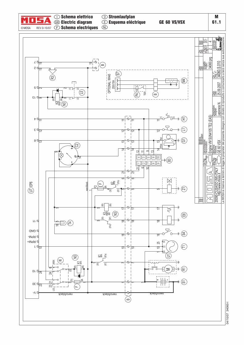
© MOSA REV.0-10/07
GE 60 VS/VSXM
61.1E
D
NL
Schema elettricoElectric diagramSchema electriques
StromlaufplanEsquema eléctrique
04/1
0/07
340
60-I
2009
0-C
US
AG
O(M
I)-I
TALY
http
://w
ww
.mos
a.it
GE
60VS
X
Engi
neVM
SUN4
105
TE2
(EAS
)34
060.
prg
3406
0.S.
010
Lepo
race
N.
2 Appr
ovat
o:
Esp.
Data
Dis.
Appr
.M
odific
a
Deno
min
azio
ne:
Mac
chin
a:Da
ta:
Prog
etto
:di
n°Pa
g.n°
4
Date
Appr
.
Appr
oved
:
Proj
ect:
Deno
min
atio
n:
Mac
hine
:
Mod
ificat
ion
Date
:
DaPa
g.
Alla
Pag.
ToPa
ge
From
Page
Desig
ner:
ofn°
Desi.
Dis.
n°:
Exp.
Page
n°
Dwg.
n°:
Dise
gnat
ore:
La
MO
SA
sirise
rva
ate
rmin
idi l
eg
ge
lap
rop
rie
ta' d
elp
rese
nte
dis
eg
no
con
div
ieto
di r
ipro
du
rlo
oco
mu
nic
arlo
ate
rzis
en
zasu
aa
uto
rizz
azi
on
e.
31
25
46
LOC.
REM
. I6
K1(8
5)
(86)
N3
avv.
K1(3
0)
(87)
(87a
)
avv.
V-
30
10
1
RPM+
GND
6
3
4
23 23
24 2421
6
10
322
1 1
1 7
1
5
2114
1211
1211
13
5
10
13 13
92
14
nero/black
nero
/bla
ck
nero/black
11
-+ C2
1
-+ M R1
-+
S1
7
B3
1 2
109
4 3 5
68
17
521
1412
1110
1412
11
13 13W
hite
Red
G1
(1)
(2)
H1
1025
15
nero/black
L1
B+W
D+
U1
T1
EP6
U7
RPM-
66
4K2
(30)
(87)
(87a
)
stop
Z15
(1)
(2)
L5
(1)
(2)
1616
T4
B
1519 19
2
7
-+
R3
B
F1
F
5A
F2
F
8A
516
S4
18
E8
5(3
0)
(87)
(87a
)
5
5 17
1817
1817
8
K3 aid
N3star
t
S7
250V
/10A
OPT
IONA
L:W
H45
M4
P4 10A
B
K2(8
5)
(86)
N3stop
21 6 10
1112 9 13
2
25.0
9.20
07
(85)
(86)
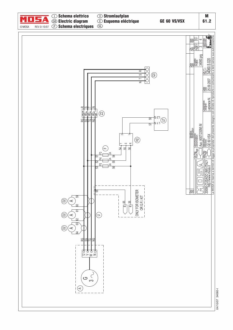
© MOSA REV.0-10/07
GE 60 VS/VSXM
61.2E
D
NL
Schema elettricoElectric diagramSchema electriques
StromlaufplanEsquema eléctrique
04/1
0/07
340
60-I
2009
0-CU
SAG
O (M
I)-IT
ALY
http
://ww
w .m
osa.
itGE
60VS
X
Aux.
(400T
/230M
) M34
060.p
rg
3406
0.S.02
0Le
porac
eN.
3 Appro
vato:
Esp.
Data
Dis.
Appr.
Modif
icaDe
nomi
nazio
ne:
Macc
hina:
Data:
Prog
etto:
di n°
Pag.n
°
4
Date
Appr.
Appro
ved:
Proje
ct:De
nomi
natio
n:
Mach
ine:Mo
difica
tion
Date:
Da P
ag.
Alla P
ag.
To P
age
From
Page
Desig
ner:
of n°
Desi.
Dis.
n°:
Exp.
Page
n°
Dwg.
n°:
Dise
gnato
re:
La M
OS
Asi
ris
erva
a te
rmin
i di l
egge
la p
ropr
ieta
' del
pre
sent
e di
segn
o co
n di
viet
o di
rip
rodu
rlo o
com
unic
arlo
a te
rzi s
enza
sua
aut
oriz
zazi
one.
R S TSG TG NG
N
RS
TN
RG
5352
5165
5960
6261
6463
RG SG TG NG
5655
54
56
54 55 56
Z2
AD2
AD2
AD2
U
3GA
NU V W
12
RST
H2
F5 2A
F4 2A
F3F
2A
L2
U7L1
5857
25.09
.2007
Q3
465
4
ONLY
FOR
ISOM
ETER
OR G
.F.I.K
IT
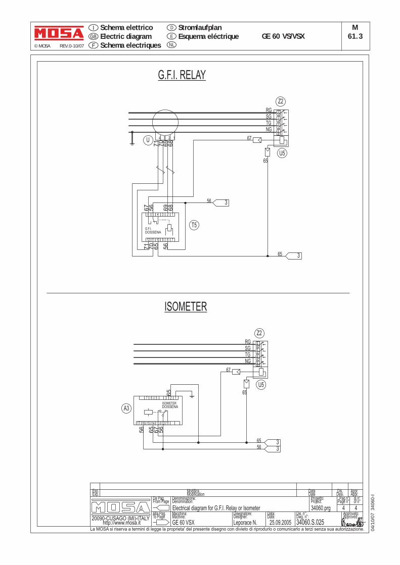
© MOSA REV.0-10/07
GE 60 VS/VSXM
61.3E
D
NL
Schema elettricoElectric diagramSchema electriques
StromlaufplanEsquema eléctrique
04/1
0/07
340
60-I
20090-CUSAGO (MI)-ITALYhttp://www.mosa.it GE 60 VSX
Electrical diagram for G.F.I. Relay or Isometer 34060.prg
34060.S.025Leporace N.
4Approvato:
Esp. Data Dis. Appr.Modifica
Denominazione:
Macchina: Data:
Progetto: di n°Pag.n°
4
Date Appr.
Approved:
Project:Denomination:
Machine:
Modification
Date:
Da Pag.
Alla Pag.To Page
From Page
Designer:
of n°
Desi.
Dis. n°:
Exp.
Page n°
Dwg. n°:Disegnatore:
La MOSA si riserva a termini di legge la proprieta' del presente disegno con divieto di riprodurlo o comunicarlo a terzi senza sua autorizzazione.
1234U
6 5 4 3 2 1
789101112
G.F.I.DOSSENA
T5
68
68
69
69
70
71
70
71
RGSGTGNG
Z2
U5
67
65
67
65
65
56
3
ISOMETER
G.F.I. RELAY
RGSGTGNG
67
65
65
6556
Z2
U5
2 13567
17 15 13 11121416
DOSSENAISOMETER
A3
56
56
67
65
3
33
56
56
25.09.2005

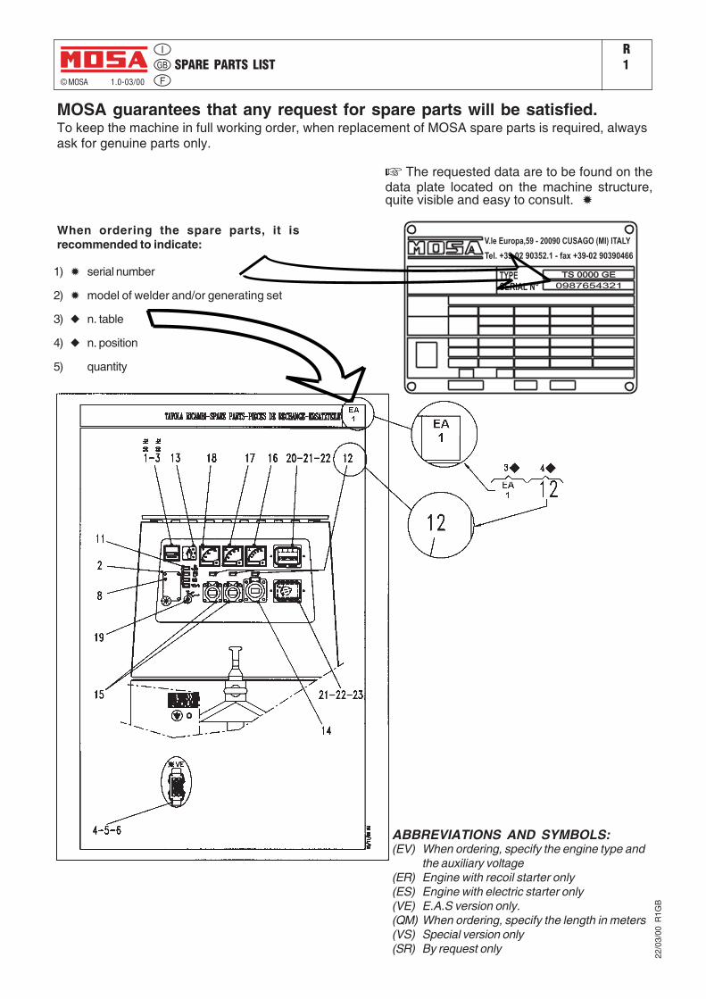
SPARE PARTS LISTR1
© MOSA 1.0-03/00
MOSA guarantees that any request for spare parts will be satisfied.To keep the machine in full working order, when replacement of MOSA spare parts is required, alwaysask for genuine parts only.
When ordering the spare parts, it isrecommended to indicate:
1) ✹ serial number
2) ✹ model of welder and/or generating set
3) ◆ n. table
4) ◆ n. position
5) quantity
TS 0000 GETS 0000 GE
V.le Europa,59 - 20090 CUSAGO (MI) ITALY
Tel. +39-02 90352.1 - fax +39-02 90390466
0987654321
TYPE
SERIAL N°
22/0
3/00
R1G
B
The requested data are to be found on thedata plate located on the machine structure,quite visible and easy to consult. ✹
ABBREVIATIONS AND SYMBOLS:(EV) When ordering, specify the engine type and
the auxiliary voltage(ER) Engine with recoil starter only(ES) Engine with electric starter only(VE) E.A.S version only.(QM) When ordering, specify the length in meters(VS) Special version only(SR) By request only
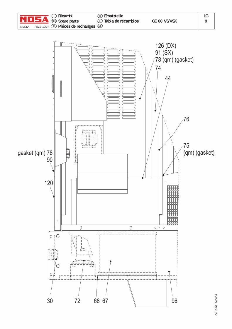
© MOSA REV.0-10/07
04/1
0/07
340
60-I
GE 60 VS/VSXIG9E
D
NL
RicambiSpare partsPiéces de rechanges
ErsatzteileTabla de recambios
75(qm) (gasket)
126 (DX)91 (SX)78 (qm) (gasket)
76
74
gasket (qm) 7890
9668 6772
120
44
30
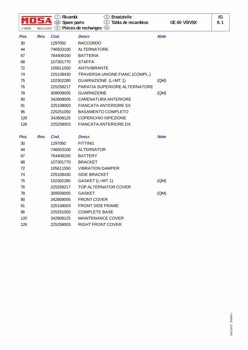
© MOSA REV.0-10/07
04/1
0/07
340
60-I
GE 60 VS/VSXIG
9.1E
D
NL
RicambiSpare partsPiéces de rechanges
ErsatzteileTabla de recambios
Pos. Rev. Cod. Descr. Note
30 1297050 RACCORDO
44 746503100 ALTERNATORE
67 764409150 BATTERIA
68 107301770 STAFFA
72 105611550 ANTIVIBRANTE
74 225108430 TRAVERSA UNIONE FIANC.(COMPL.)
75 102302280 GUARNIZIONE (L=MT.1) (QM)
76 225258217 PARATIA SUPERIORE ALTERNATORE
78 309509005 GUARNIZIONE (QM)
90 342808005 CARENATURA ANTERIORE
91 225108003 FIANCATA ANTERIORE SX
96 225251050 BASAMENTO COMPLETO
120 342808125 COPERCHIO ISPEZIONE
126 225258003 FIANCATA ANTERIORE DX
Pos. Rev. Cod. Descr. Note
30 1297050 FITTING
44 746503100 ALTERNATOR
67 764409150 BATTERY
68 107301770 BRACKET
72 105611550 VIBRATION DAMPER
74 225108430 SIDE BRACKET
75 102302280 GASKET (L=MT.1) (QM)
76 225258217 TOP ALTERNATOR COVER
78 309509005 GASKET (QM)
90 342808005 FRONT COVER
91 225108003 FRONT SIDE FRAME
96 225251050 COMPLETE BASE
120 342808125 MAINTENANCE COVER
126 225258003 RIGHT FRONT COVER
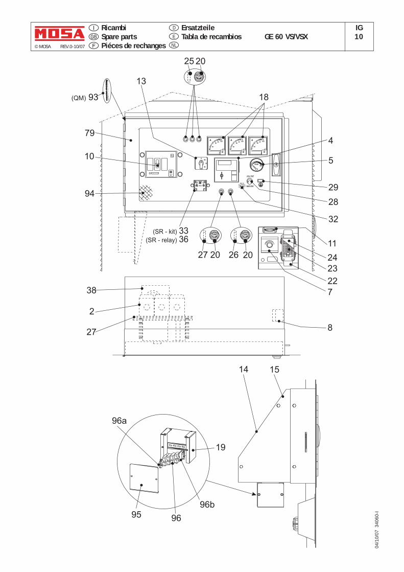
© MOSA REV.0-10/07
04/1
0/07
340
60-I
GE 60 VS/VSXIG10E
D
NL
RicambiSpare partsPiéces de rechanges
ErsatzteileTabla de recambios
FUSE
FUSE
40
A
20
30060
40
A
20
30060
ST
0TR
0RS
40
A
20
30060
FUSEFUSE
1514
18
19
38
2
278
7
11
26
(SR - kit)
(SR - relay)
3336
94
95
23
24
29
13
20
10
22
25 20
28
79
(QM) 93
32
96a
96
96b
EM
ERGEN
CY
TANK0 4/4
FUSE
0.02
0.1
0.25
0.5
I° (A)
TRIP2.5 ON
2
0.5
0.4
t (s)
x0.1I°
1.51
RESET
tx1MA
I°x1tx10
x10
RESET
0.30.2
TEST
FUSEFUSE
ON
PUSH TO TRIP
I
N
0 .6 3 x I n
0 .8 x I n
x I n1
REMOTE START
LOCAL START
5
FUSE
27 20
4
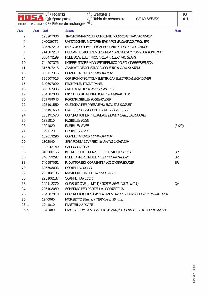
© MOSA REV.0-10/07
04/1
0/07
340
60-I
GE 60 VS/VSXIG
10.1E
D
NL
RicambiSpare partsPiéces de rechanges
ErsatzteileTabla de recambios
Pos. Rev. Cod. Descr. Note
2 125207306 TRASFORMATORE DI CORRENTE / CURRENT TRANSFORMER4 JK0029770 UNITA’CONTR. MOTORE (EP6) / PCB ENGINE CONTROL EP65 325507210 INDICATORE LIVELLO CARBURANTE / FUEL LEVEL GAUGE7 744507219 PULSANTE STOP D’EMERGENZA / EMERGENCY PUSH BUTTON STOP8 306479199 RELE’ AVV. ELETTRICO / RELAY, ELECTRIC START
10 744507325 INTERRUTTORE MAGNETOTERMICO / CIRCUIT BREAKER BOX11 315507215 AVVISATORE ACUSTICO / ACOUSTIC ALARM SYSTEM13 305717315 COMMUTATORE / COMMUTATOR14 325507015 COPERCHIO SCATOLA ELETTRICA / ELECTRICAL BOX COVER15 340607020 FRONTALE / FRONT PANEL18 325257305 AMPEROMETRO / AMPEROMETER19 734507308 CASSETTA ALIMENTAZIONE / TERMINAL BOX20 307759045 PORTAFUSIBILE / FUSE HOLDER22 105191550 CUSTODIA PER PRESA EAS / BOX, EAS SOCKET23 105191560 FRUTTO PRESA CONNETTORE / SOCKET, EAS24 105191570 COPERCHIO PER PRESA EAS / BLIND PLATE, EAS SOCKET25 1291010 FUSIBILE / FUSE26 1291020 FUSIBILE / FUSE (5x20)27 1291120 FUSIBILE / FUSE28 102013290 COMMUTATORE / COMMUTATOR29 1302040 SPIA ROSSA 12V / RED WARNING LIGHT 12V32 102042740 CAPPUCCIO / CAP33 340600165 KIT RELE’ DIFFERENZ. ELETTRONICO / GFI KIT SR36 740559297 RELE’ DIFFERENZIALE / ELECTRONIC RELAY SR38 740557052 RIDUTTORE DI CORRENTE / VOLTAGE REDUCER SR79 325508093 PORTELLA / DOOR87 225108136 MANIGLIA COMPLETA / KNOB ASSY88 225108137 SCARPETTA / LOCK93 105112270 GUARNIZIONE (L=MT.1) / STRIP, SEALING (L=MT.1) QM94 225108089 SCHERMO PER PORTELLA / PROTECTION95 734507313 COPERCHIO CHIUS.CASS.ALIMENTAZ. / CLOSING COVER TERMINAL BOX96 1240060 MORSETTO 35mmq / TERMINAL 35mmq96 a 1241010 PIASTRINA / PLATE96 b 1242080 PIASTR.TERM. X MORSETTO 35MMQ / THERMAL PLATE FOR TERMINAL
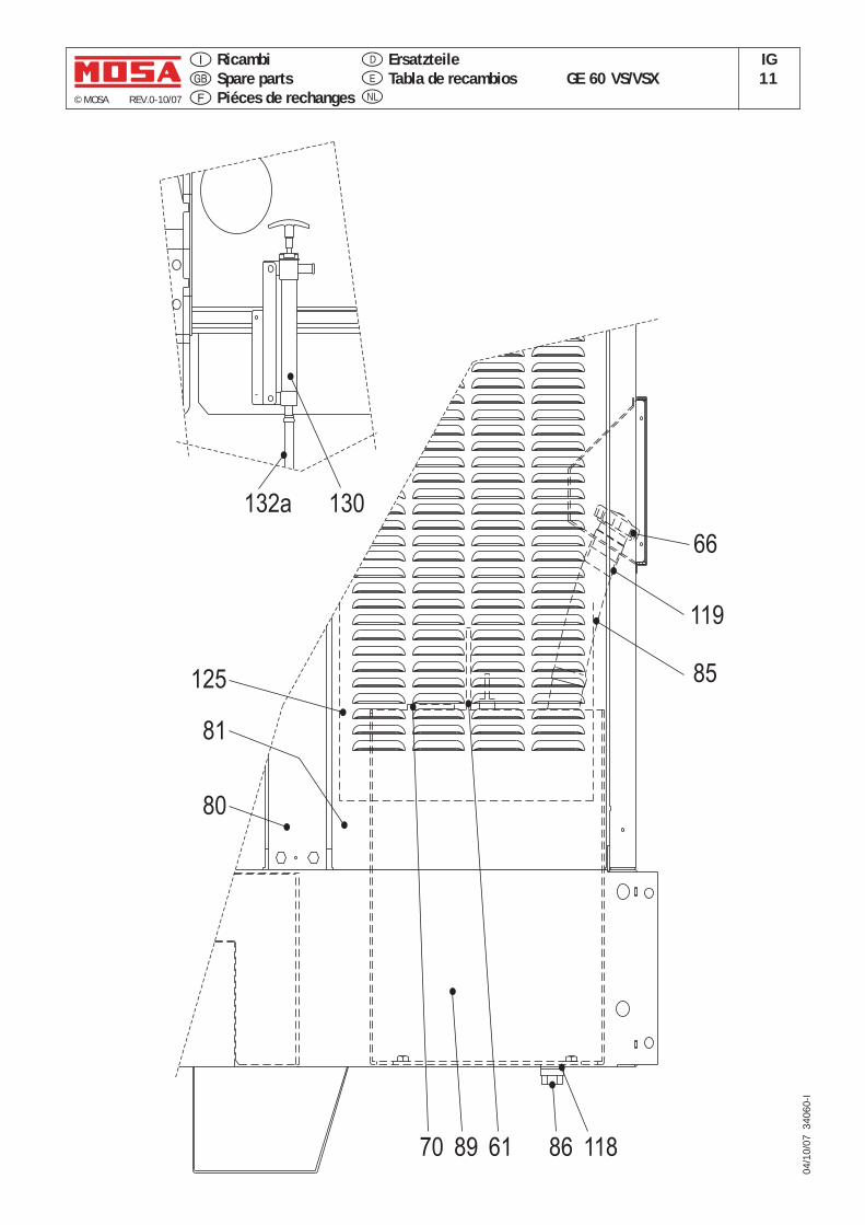
© MOSA REV.0-10/07
04/1
0/07
340
60-I
GE 60 VS/VSXIG11E
D
NL
RicambiSpare partsPiéces de rechanges
ErsatzteileTabla de recambios
132a 130
66
119
85
8970 61 86 118
125
80
81
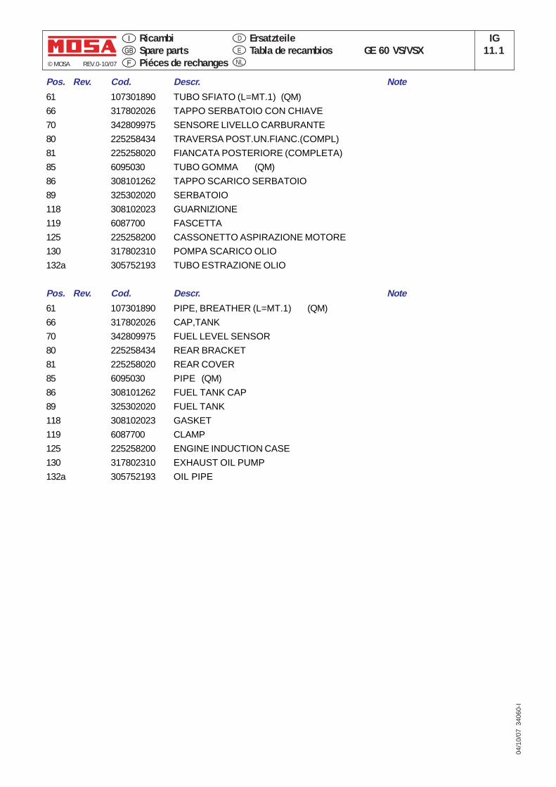
© MOSA REV.0-10/07
04/1
0/07
340
60-I
GE 60 VS/VSXIG
11.1E
D
NL
RicambiSpare partsPiéces de rechanges
ErsatzteileTabla de recambios
Pos. Rev. Cod. Descr. Note
61 107301890 TUBO SFIATO (L=MT.1) (QM)
66 317802026 TAPPO SERBATOIO CON CHIAVE
70 342809975 SENSORE LIVELLO CARBURANTE
80 225258434 TRAVERSA POST.UN.FIANC.(COMPL)
81 225258020 FIANCATA POSTERIORE (COMPLETA)
85 6095030 TUBO GOMMA (QM)
86 308101262 TAPPO SCARICO SERBATOIO
89 325302020 SERBATOIO
118 308102023 GUARNIZIONE
119 6087700 FASCETTA
125 225258200 CASSONETTO ASPIRAZIONE MOTORE
130 317802310 POMPA SCARICO OLIO
132a 305752193 TUBO ESTRAZIONE OLIO
Pos. Rev. Cod. Descr. Note
61 107301890 PIPE, BREATHER (L=MT.1) (QM)
66 317802026 CAP,TANK
70 342809975 FUEL LEVEL SENSOR
80 225258434 REAR BRACKET
81 225258020 REAR COVER
85 6095030 PIPE (QM)
86 308101262 FUEL TANK CAP
89 325302020 FUEL TANK
118 308102023 GASKET
119 6087700 CLAMP
125 225258200 ENGINE INDUCTION CASE
130 317802310 EXHAUST OIL PUMP
132a 305752193 OIL PIPE
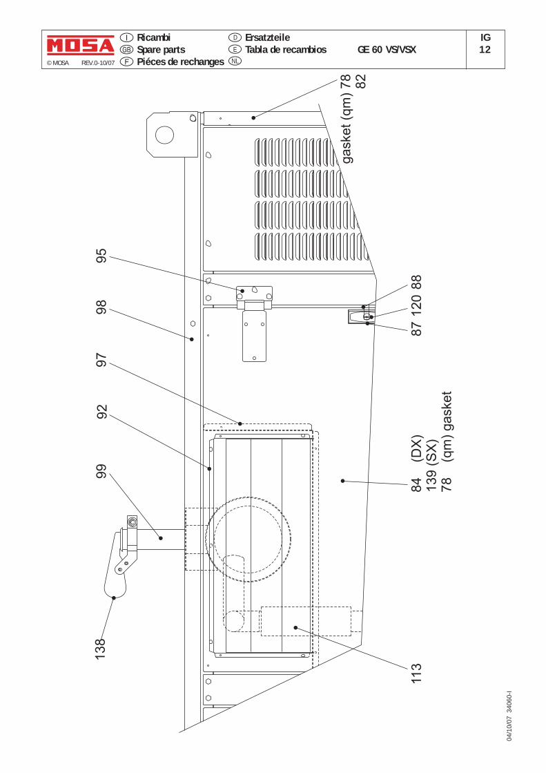
© MOSA REV.0-10/07
04/1
0/07
340
60-I
GE 60 VS/VSXIG12E
D
NL
RicambiSpare partsPiéces de rechanges
ErsatzteileTabla de recambios
ga
ske
t(q
m)
78
82
95
98
97
92
99
11
38
4(D
X)
13
9(S
X)
78
(qm
)g
aske
t
87
12
0
13
8
88
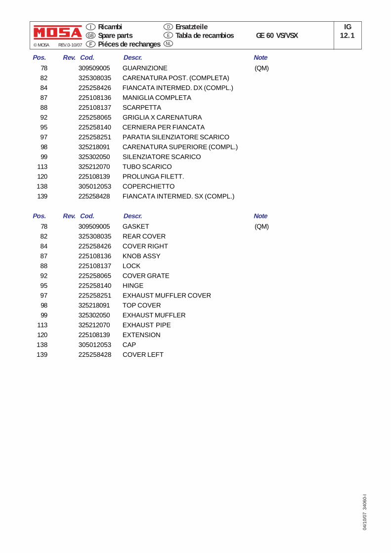
© MOSA REV.0-10/07
04/1
0/07
340
60-I
GE 60 VS/VSXIG
12.1E
D
NL
RicambiSpare partsPiéces de rechanges
ErsatzteileTabla de recambios
Pos. Rev. Cod. Descr. Note
78 309509005 GUARNIZIONE (QM)
82 325308035 CARENATURA POST. (COMPLETA)
84 225258426 FIANCATA INTERMED. DX (COMPL.)
87 225108136 MANIGLIA COMPLETA
88 225108137 SCARPETTA
92 225258065 GRIGLIA X CARENATURA
95 225258140 CERNIERA PER FIANCATA
97 225258251 PARATIA SILENZIATORE SCARICO
98 325218091 CARENATURA SUPERIORE (COMPL.)
99 325302050 SILENZIATORE SCARICO
113 325212070 TUBO SCARICO
120 225108139 PROLUNGA FILETT.
138 305012053 COPERCHIETTO
139 225258428 FIANCATA INTERMED. SX (COMPL.)
Pos. Rev. Cod. Descr. Note
78 309509005 GASKET (QM)
82 325308035 REAR COVER
84 225258426 COVER RIGHT
87 225108136 KNOB ASSY
88 225108137 LOCK
92 225258065 COVER GRATE
95 225258140 HINGE
97 225258251 EXHAUST MUFFLER COVER
98 325218091 TOP COVER
99 325302050 EXHAUST MUFFLER
113 325212070 EXHAUST PIPE
120 225108139 EXTENSION
138 305012053 CAP
139 225258428 COVER LEFT
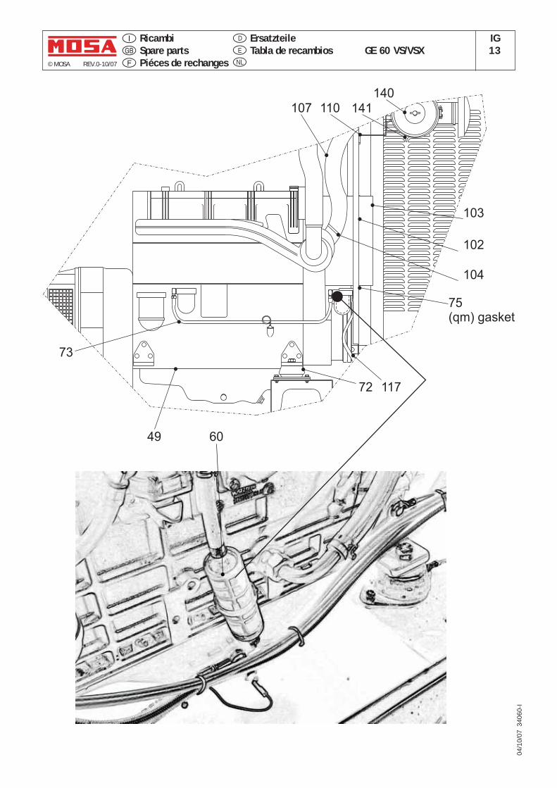
© MOSA REV.0-10/07
04/1
0/07
340
60-I
GE 60 VS/VSXIG13E
D
NL
RicambiSpare partsPiéces de rechanges
ErsatzteileTabla de recambios
107
49
110
73
117
60
72
75(qm) gasket
102
103
140
141
104
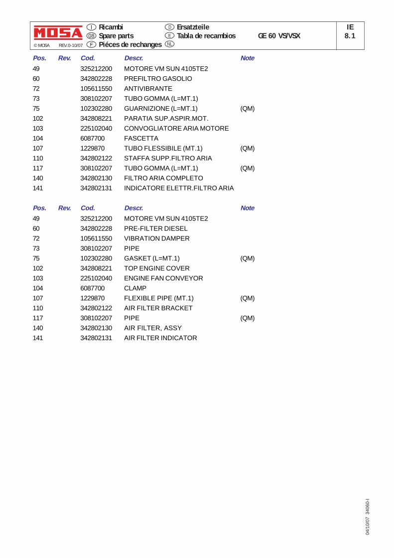
Pos. Rev. Cod. Descr. Note
49 325212200 MOTORE VM SUN 4105TE2
60 342802228 PREFILTRO GASOLIO
72 105611550 ANTIVIBRANTE
73 308102207 TUBO GOMMA (L=MT.1)
75 102302280 GUARNIZIONE (L=MT.1) (QM)
102 342808221 PARATIA SUP.ASPIR.MOT.
103 225102040 CONVOGLIATORE ARIA MOTORE
104 6087700 FASCETTA
107 1229870 TUBO FLESSIBILE (MT.1) (QM)
110 342802122 STAFFA SUPP.FILTRO ARIA
117 308102207 TUBO GOMMA (L=MT.1) (QM)
140 342802130 FILTRO ARIA COMPLETO
141 342802131 INDICATORE ELETTR.FILTRO ARIA
Pos. Rev. Cod. Descr. Note
49 325212200 MOTORE VM SUN 4105TE2
60 342802228 PRE-FILTER DIESEL
72 105611550 VIBRATION DAMPER
73 308102207 PIPE
75 102302280 GASKET (L=MT.1) (QM)
102 342808221 TOP ENGINE COVER
103 225102040 ENGINE FAN CONVEYOR
104 6087700 CLAMP
107 1229870 FLEXIBLE PIPE (MT.1) (QM)
110 342802122 AIR FILTER BRACKET
117 308102207 PIPE (QM)
140 342802130 AIR FILTER, ASSY
141 342802131 AIR FILTER INDICATOR
© MOSA REV.0-10/07
04/1
0/07
340
60-I
GE 60 VS/VSXIE
8.1E
D
NL
RicambiSpare partsPiéces de rechanges
ErsatzteileTabla de recambios
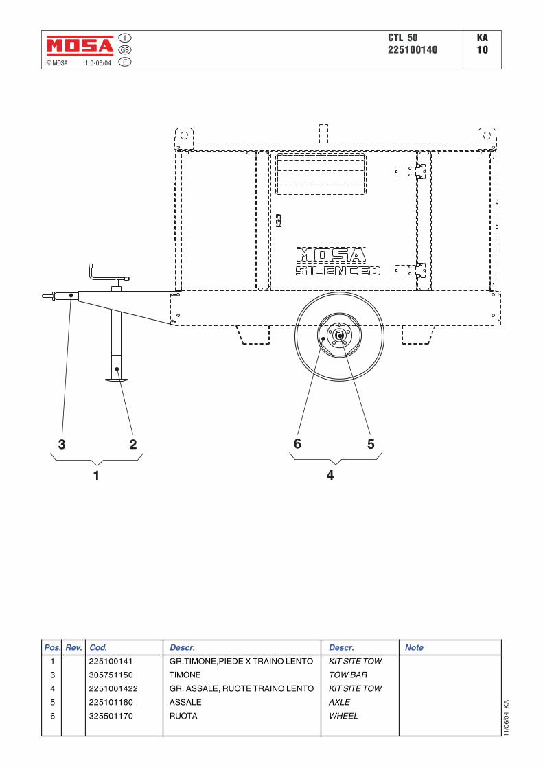
© MOSA 1.0-06/04
11/0
6/04
KA
CTL 50225100140
KA10
Pos. Rev. Cod. Descr. Descr. Note
1 225100141 GR.TIMONE,PIEDE X TRAINO LENTO KIT SITE TOW
3 305751150 TIMONE TOW BAR
4 2251001422 GR. ASSALE, RUOTE TRAINO LENTO KIT SITE TOW
5 225101160 ASSALE AXLE
6 325501170 RUOTA WHEEL
3 2
1
6 5
4
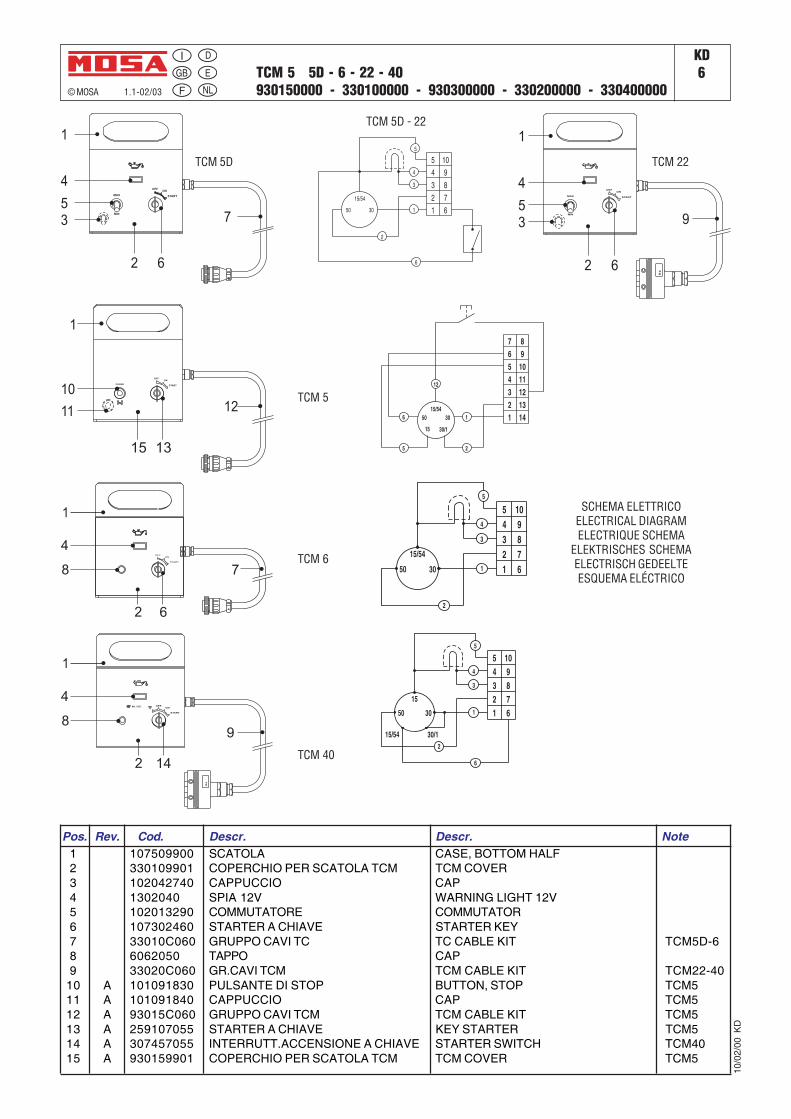
TCM 5 5D - 6 - 22 - 40930150000 - 330100000 - 930300000 - 330200000 - 330400000
KD6
© MOSA 1.1-02/03
10/0
2/00
KD
SCHEMA ELETTRICOELECTRICAL DIAGRAMELECTRIQUE SCHEMA
ELEKTRISCHES SCHEMAELECTRISCH GEDEELTEESQUEMA ELÉCTRICO
E
D
NL
Pos. Rev. Cod. Descr. Descr. Note1 107509900 SCATOLA CASE, BOTTOM HALF2 330109901 COPERCHIO PER SCATOLA TCM TCM COVER3 102042740 CAPPUCCIO CAP4 1302040 SPIA 12V WARNING LIGHT 12V5 102013290 COMMUTATORE COMMUTATOR6 107302460 STARTER A CHIAVE STARTER KEY7 33010C060 GRUPPO CAVI TC TC CABLE KIT TCM5D-68 6062050 TAPPO CAP9 33020C060 GR.CAVI TCM TCM CABLE KIT TCM22-40
10 A 101091830 PULSANTE DI STOP BUTTON, STOP TCM511 A 101091840 CAPPUCCIO CAP TCM512 A 93015C060 GRUPPO CAVI TCM TCM CABLE KIT TCM513 A 259107055 STARTER A CHIAVE KEY STARTER TCM514 A 307457055 INTERRUTT.ACCENSIONE A CHIAVE STARTER SWITCH TCM4015 A 930159901 COPERCHIO PER SCATOLA TCM TCM COVER TCM5
TCM 5
TCM 5D
TCM 6
TCM 22
TCM 40
TCM 5D - 22
