gd&t - faculty of mechanical engineeringfkm.utm.my/~jinhoe/notes/skmv4792 automotive...
TRANSCRIPT

GD&T

What is GD&T
• ASME Y14.5M-1994
• -The national standard for dimensioning and tolerancing in theUnited States.
• ASME stands for American Society of Mechanical Engineers.
• The Y14.5 is the standard number.
• "M" is to indicate the standard is metric, and 1994 is the date the standard was officially approved.

What is GD&T
• Geometric Dimensioning and tolerancing (GD&T) isa language used on mechanical engineering drawings composed of symbols that are used to efficiently and accurately communicate geometry requirements for associated features on component and assemblies.
• A method to specify the shape of a piece of hardware on an engineering drawing.

• A set of fourteen symbols used in the language of GD&T. It consists of well-defined of symbols, rules, definitions and conventions, used on engineering drawings to accurately describe a part.
• GD&T is a precise mathematical language that can be used to describe the size, form, orientation, and location of part features.
• GD&T is also a design philosophy on how to design and dimension parts
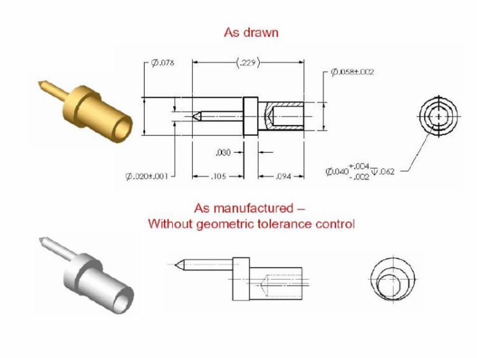

Example of part with no GD&T

Example part with GD&T

Compare!

Manufactured parts

Advantages of GD&T
• Use of this language or tool “can provide economic and technical advantage” stated the ASME.
• Maximizes quality of the products.
• Provides uniformity of specification and interpretation(reducing guesswork and controversy)

• Geometric dimensioning dramatically reduces the need for drawing notes to describe complex geometry requirements on a component or assembly by the use of standard symbology

Advantages of GD&T
• Ensures the design requirements are carried out.
• GD&T facilitates an efficient means to communicate specific datums on a part. Without the use of a datum system (zero reference) on a part, it is not clear to manufacturing or quality where to manufacture or measure from. Additionally, the use of datums dramatically simplifies the design and specification of parts for use in manufacturing and quality verification steps.

Advantages of GD&T
• Create a part design that focuses on the product function. • Convert product requirements into dimensional
specifications. • Better define parts without the need for assumptions. • Document the design for future use. • Discover problems in the design stage • Ensure that parts will assemble. • Have less "hand fitting" at assembly. • Ensure that parts are inspected as intended. • Inspect parts more quickly. • Reduce scrap or rework. • Make a replacement that fits into the assembly

Advantages of GD&T
• Have multiple sources on various parts of an assembly. • Make valid engineering calculations. • Have common parts across similar assemblies. • Design subassemblies in different locations andhave them
function correctly. • Do tolerance analysis to study the effect of parttolerances
on the assembly. • Use state of the art software tools to analyze parts inan
assembly. • Use state of the art software tools to inspect the parts. • Reduce the risk caused by vague specifications. • saves money

Geometric Tolerances are divided into five categories
• 1.Form control
• 2.Orientation control
• 3.Location control
• 4.Composite control
• 5.Profile controls

Form control

Orientation control

Location control

Composite control

Profile control

Summary of control tolerances
• Orientation is refinement of location.
• Form is refinement of orientation

Geometric Dimensioning &Tolerancing symbols

modifiers

Feature control symbols with datum references

Datum

datum

Datum vs datum feature

Datum feature symbol
• When the datum is the axis or center plane

Datum feature symbol

datum targets
• The datum targets are indicated by a circular frame divided in two compartments by a horizontal line.
• The lower compartment is reserved for a letter and a digit.
• The letter represents the datum feature and the digit datum target number.
• The upper compartment is reserved for additional information, such as dimensions of the target area.

Datum target
• A specified point, line or area on a part used to establish a datum.

Common datum
• A common_datum is a type of Datum that corresponds to a datumt hat is established from more than one datum feature.
• On technical drawing, a datum that is established from multiple datum features is indicated by by placing the identifying letters of the datum features, separated by a dash, within a single compartment in a feature control frame.
• There is no significance to the order of the datum feature identifying letters within a compartment of the feature control frame
Datum system
• A group of two or more separate datumsused as a combined reference for atoleranced feature.
Datum reference frame
Datum reference frames are coordinate systems used to locate and orient part features.

Datum reference frame
• A framework that consists of three mutually perpendicular datum planes, three datum axes(located at the intersection of each pair of datum planes), and a datum point (that is located at the intersection of the three datum planes).
• A Cartesian coordinate system established using the Datums extracted from a set of Datum Features referenced in a Feature Control Frame. Datum Reference Frames serve to orient and locate tolerance zones.

Datum reference frame


Material conditions
• Features of size which includes datum features have size tolerances
• The size condition or material (amount of metal) condition can vary from maximum metal condition (MMC) to the least metal condition (LMC)
• If the center planes or axes of a feature of size are controlled by geometric tolerances a modifying symbol can be specified in the feature control frame, that applies the tolerance value either MMC or LMC
• Can also use for a datum that a feature of size
• If a symbol is not specified – regardless of material condition, use RFS (regardless of feature size)

Regardless of Feature Size (RFS):
• It is applicable if theMMC or the LMC are not specified for individual features of size tolerances or for datum featuresof size.
• The tolerance is limited to the specified value in the FCF and if applied to a datum feature of size the actual axis or center plane have to be established regardless of the feature size.
• It is always used for run out, concentricity, and symmetry controls • It is also used when targets are specified to establish datum axes
and center plane sbecause the targets have to contact the datum features to be useful.
• Also it is used to control wall thickness variation between external and internal features. Hard gages are not applicable since there is no additional or bonus tolerance as allowed for MMC and LMC.

Example: RFS

Maximum Material Condition (MMC)
• The condition in which a feature of size contains the maximum amount of material every where within the stated limits of size

Maximum Material Condition (MMC)

MMC vs LMC

Least Material Condition (MMC)
• The condition in which a feature of size contains the least amount of material everywhere within the stated limits of size

Maximum Material Condition (MMC)
• This is the condition when the actual mating size or envelope size is at the maximum material condition which is maximum size for an external feature such as a cylinder and the minimum size for an internal feature such as a hole. The symbol is “M”
• The added tolerance is the difference between the actual mating envelope size and the MMC size.
• the largest actual mating envelope named virtual condition is equal to the MMC size plus the tolerance specified in the FCF for an external feature and minus for an internal feature.
• The MMC symbol is used to assure that parts will assemble and it allows the use of so called hard gages (go gages) for quick inspections.
• The actual local size has to meet the size tolerance however the actual local size does not affect the geometric characteristic tolerance

Maximum metal condition

Least Material Condition (LMC) • This is the opposite of MMC
• this is the condition when the actual minimum mating size or envelope is at the minimum material condition which is minimum size for an external feature such as a cylinder and the maximum size for an internal feature such as a hole. The symbol is “L”
• the smallest actual mating size is equal to the LMC size minus the tolerance specified in the FCF for an external feature and plus for an internal feature.
• The LMC symbol is used to assure a minimum amount of machining stock for features that are to be machined and for assuring a minimum amount of wall thickness between external and internal features.
• Hard gages cannot be used for inspection • the actual local size has to meet the size tolerance however the
local size does not affect the geometric characteristic tolerance

Least metal condition

Maximum and minimum material condition – two hole patterns

True-position dimensioning

roundness

cylindricity

Concentricity
• Concentricity describes a condition in which two or more features (cylinders, cones, spheres, etc.) In any combination have a common axis.

concetricity

Straightness

Angular

Flatness

Flatness
• All surface elements of the tolerance feature must lie between two parallel planes 0.2 apart.

Flatness Applications
• To ensure the integrity of mating or mounting surfaces
• To ensure that surfaces seal properly
• Appearance

Flatness – flange mounting

Flatness – sealing surface
• Flatness control - to ensure proper gasket compression

Flatness- sealing surface

Angularity

Profile

Profile

concentricity

perpendicularity


Parallelism

Parallelism


Circular runout
• A dial indicator is often used to verify a runout control
• First, the part is located in a chuck or collet to establish datum axis A.
• A dial indicator is placed on the surface being checked.
• As the part is rotated 360 degree, the dial indicator movement is the run out value of the circular element.
• Several independent dial indicator readings are made at different places along the diameter.

Total runout
• Total run out is used to control the combined variations of circularity, straightness, coaxiality, angularity, taper and profile when applied to surfaces around and at right angles to a datum axis.
• Note that total runout cannot be applied to conical or curved surfaces as can circular runout.

Run-out


Application of GD&T

Surface texture symbols

Application of surface texture symbol

Lay symbols