gcp-30 series genset control - precision controls ... · 37239a installation software version...
TRANSCRIPT
37239A
Installation Software Version 4.3xxx
Manual 37239A
GCP-30 Series Genset Control

Manual 37239A GCP-30 Series - Genset Control
Page 2/47 © Woodward
WARNING Read this entire manual and all other publications pertaining to the work to be performed before install-ing, operating, or servicing this equipment. Practice all plant and safety instructions and precautions. Failure to follow instructions can cause personal injury and/or property damage. The engine, turbine, or other type of prime mover should be equipped with an overspeed (overtempera-ture, or overpressure, where applicable) shutdown unit(s), that operates totally independently of the prime mover control unit(s) to protect against runaway or damage to the engine, turbine, or other type of prime mover with possible personal injury or loss of life should the mechanical-hydraulic gover-nor(s) or electric control(s), the actuator(s), fuel control(s), the driving mechanism(s), the linkage(s), or the controlled unit(s) fail.
CAUTION To prevent damage to a control system that uses an alternator or battery-charging unit, make sure the charging unit is turned off before disconnecting the battery from the system. Electronic controls contain static-sensitive parts. Observe the following precautions to prevent dam-age to these parts. • Discharge body static before handling the control (with power to the control turned off, contact a
grounded surface and maintain contact while handling the control). • Avoid all plastic, vinyl, and Styrofoam (except antistatic versions) around printed circuit boards. • Do not touch the components or conductors on a printed circuit board with your hands or with
conductive units. Important Definitions
WARNING Indicates a potentially hazardous situation that, if not avoided, could result in death or serious injury. Appropriate precautions have to be taken.
CAUTION Indicates a potentially hazardous situation that, if not avoided, could result in damage to equipment. This note should absolutely be observed when connecting the control.
NOTE References to other notes and supplements as well as tables and lists are identified by means of the "i" symbol. Most of the referenced sections are included in the Annex.
Woodward Governor Company reserves the right to update any portion of this publication at any time. Information provided by Wood-ward Governor Company is believed to be correct and reliable. However, Woodward Governor Company assumes no responsibility unless otherwise expressly undertaken.
© Woodward Governor Company
All Rights Reserved.
Manual 37239A GCP-30 Series - Genset Control
© Woodward Page 3/47
Revision History
Rev. Date Editor Changes NEW 04-06-02 Tr Release A 04-09-23 TP Update: wiring of multi-functional three-position controller, functionality V4.3xxx
Contents
NOTE All functions described in this manual are included in all controls (all versions) of the GCP-30 and AMG 2 series. Any differences between the control units will be indicated by having the model number for the applicable control unit at the beginning of the text. Please note that the AMG series controller is not explicitly described in this manual. [GCP-32] The functions marked and described for applications with 2 power circuit breakers (control
types GCP-32 and AMG 2/N2PB). [GCP-31] The functions marked and described for applications with 1 power circuit breaker (control
types GCP-31 and AMG 2/N1PB).
CHAPTER 1. GENERAL INFORMATION.........................................................................................7 Related Documents.................................................................................................................................7 CHAPTER 2. ELECTROSTATIC DISCHARGE AWARENESS .............................................................8 CHAPTER 3. HOUSING ...............................................................................................................9 Dimensions .............................................................................................................................................9 Panel Cut-Out .......................................................................................................................................10 Side view...............................................................................................................................................11 Installation .............................................................................................................................................12 CHAPTER 4. WIRING DIAGRAMS - OVERVIEW ...........................................................................13 GCP-31/BPD Package..........................................................................................................................14 GCP-31/BPQ Package .........................................................................................................................15 GCP-31/XPD Package..........................................................................................................................16 GCP-31/XPQ Package .........................................................................................................................17 GCP-31/XPQ+SB03 Package ..............................................................................................................18 GCP-31/XPQ+SC06 Package ..............................................................................................................19 GCP-32/BPD Package..........................................................................................................................20 GCP-32/BPQ Package .........................................................................................................................21 GCP-32/XPD Package..........................................................................................................................22 GCP-32/XPQ Package .........................................................................................................................23 GCP-32/XPQ+SB03 Package ..............................................................................................................24 GCP-32/XPQ+SC06 Package ..............................................................................................................25
Manual 37239A GCP-30 Series - Genset Control
Page 4/47 © Woodward
CHAPTER 5. CONNECTORS - DETAILS ..................................................................................... 26 Power Supply........................................................................................................................................ 26 Measuring Inputs .................................................................................................................................. 27
Voltage ....................................................................................................................................... 27 Current........................................................................................................................................ 29
Discrete Inputs...................................................................................................................................... 31 Control Inputs ............................................................................................................................. 31 Alarm Inputs ............................................................................................................................... 32 Operation Mode Selection Via DI (Option A2, from V4.3010) ................................................... 34
Analog Inputs (Packages XP, Option T701)......................................................................................... 35 Pick-Up ................................................................................................................................................. 36 Relay Outputs ....................................................................................................................................... 37
Controller Outputs ...................................................................................................................... 37 Relay Manager ........................................................................................................................... 37
Analog Outputs (Package XP, Option A2) ........................................................................................... 38 Controller Outputs ................................................................................................................................ 38
Three-Position Controller (Packages D) .................................................................................... 38 Multi Functional Controller Outputs (Package Q, Option Q)...................................................... 39
Interface................................................................................................................................................ 41 Interface Wiring .......................................................................................................................... 41 CAN Bus Shielding..................................................................................................................... 42 The CAN Bus Loop .................................................................................................................... 42 DPC - Direct Configuration Interface.......................................................................................... 42
CHAPTER 6. TECHNICAL DATA ................................................................................................ 43 CHAPTER 7. ACCURACY.......................................................................................................... 46
Manual 37239A GCP-30 Series - Genset Control
© Woodward Page 5/47
Illustrations and Tables
Illustrations Figure 3-1: Housing - Dimensions ............................................................................................................................................. 9 Figure 3-2: Housing - Control panel cut-out ............................................................................................................................ 10 Figure 3-3: Side view – without clamps................................................................................................................................... 11 Figure 3-4: Side view – with clamps........................................................................................................................................ 11 Figure 4-1: Wiring diagram GCP-31/BPD Package ................................................................................................................ 14 Figure 4-2: Wiring diagram GCP-31/BPQ Package ................................................................................................................ 15 Figure 4-3: Wiring diagram GCP-31/XPD Package ................................................................................................................ 16 Figure 4-4: Wiring diagram GCP-31/XPQ Package ................................................................................................................ 17 Figure 4-5: Wiring diagram GCP-31/XPQ+SB03 Package ..................................................................................................... 18 Figure 4-6: Wiring diagram GCP-31/XPQ+SC06 Package ..................................................................................................... 19 Figure 4-7: Wiring diagram GCP-32/BPD Package ................................................................................................................ 20 Figure 4-8: Wiring diagram GCP-32/BPQ Package ................................................................................................................ 21 Figure 4-9: Wiring diagram GCP-32/XPD Package ................................................................................................................ 22 Figure 4-10: Wiring diagram GCP-32/XPQ Package .............................................................................................................. 23 Figure 4-11: Wiring diagram GCP-32/XPQ+SB03 Package ................................................................................................... 24 Figure 4-12: Wiring diagram GCP-32/XPQ+SC06 Package ................................................................................................... 25 Figure 5-1: Power supply......................................................................................................................................................... 26 Figure 5-2: Measuring inputs - Voltage - Generator ................................................................................................................ 27 Figure 5-3: Measuring inputs - Voltage - Busbar..................................................................................................................... 28 Figure 5-4: Measuring inputs - Voltage - Mains...................................................................................................................... 28 Figure 5-5: Measuring inputs - Current - Generator ................................................................................................................ 29 Figure 5-6: Measuring inputs - Current - Mains – via transformer .......................................................................................... 30 Figure 5-7: Measuring inputs - Current - Mains – via measuring transducer........................................................................... 30 Figure 5-8: Discrete inputs – Control inputs ............................................................................................................................ 31 Figure 5-9: Discrete inputs – Alarm inputs - positive logic ..................................................................................................... 32 Figure 5-10: Discrete inputs – Alarm inputs - negative logic (Example)................................................................................. 33 Figure 5-11: Analog inputs - Package XP, Option T701 ......................................................................................................... 35 Figure 5-12: Pickup.................................................................................................................................................................. 36 Figure 5-13: Pickup – Typical behavior of the input voltage sensitivity ................................................................................. 36 Figure 5-14: Relay outputs – Controller outputs – CB activation............................................................................................ 37 Figure 5-15: Relay outputs – Relay manager........................................................................................................................... 37 Figure 5-16: Analog outputs .................................................................................................................................................... 38 Figure 5-17: Controller – Three-position controller................................................................................................................. 38 Figure 5-18: Three-position controller – external RC wiring for relay .................................................................................... 39 Figure 5-19: Analog controller output n/f/P – Wiring and external jumper setting ................................................................. 40 Figure 5-20: Analog controller output V/Q – Wiring and jumper setting ................................................................................ 40 Figure 5-21: Interface - Terminals ........................................................................................................................................... 41 Figure 5-22: Interface – CAN bus shielding ............................................................................................................................ 42 Figure 5-23: Interfaces – Loop the CAN bus ........................................................................................................................... 42
Manual 37239A GCP-30 Series - Genset Control
Page 6/47 © Woodward
Tables Table 1-1: Manual - Overview................................................................................................................................................... 7 Table 3-1: Housing - panel cut-out .......................................................................................................................................... 10 Table 5-1: Terminal assignment - power supply...................................................................................................................... 26 Table 5-2: Terminal assignment - generator voltage measuring .............................................................................................. 27 Table 5-3: Terminal assignment - busbar voltage measuring .................................................................................................. 28 Table 5-4: Terminal assignment - mains voltage measuring.................................................................................................... 28 Table 5-5: Terminal assignment - generator current measuring .............................................................................................. 29 Table 5-6: Terminal assignment - mains current measuring .................................................................................................... 30 Table 5-7: Terminal assignment - mains current measuring .................................................................................................... 30 Table 5-8: Terminal assignment - control inputs ..................................................................................................................... 31 Table 5-9: Terminal assignment - alarm inputs positive logic ................................................................................................. 32 Table 5-10: Terminal assignment - alarm inputs negative logic .............................................................................................. 33 Table 5-11: Discrete inputs - operation mode selection........................................................................................................... 34 Table 5-12: Analog inputs - terminal assignment .................................................................................................................... 35 Table 5-13: Pickup - terminal assignment ............................................................................................................................... 36 Table 5-14: Pickup – minimum input voltage.......................................................................................................................... 36 Table 5-15: Relay outputs - terminal assignment .................................................................................................................... 37 Table 5-16: Relay manager - terminal assignment................................................................................................................... 37 Table 5-17: Analog outputs - terminal assignment .................................................................................................................. 38 Table 5-18: Controller outputs - terminal assignment.............................................................................................................. 38 Table 5-19: Controller outputs - three-position ....................................................................................................................... 39 Table 5-20: Controller outputs - analog or PWM .................................................................................................................... 40 Table 5-21: Controller outputs - analog................................................................................................................................... 40 Table 5-22: Interface - terminal assignment ............................................................................................................................ 41
Manual 37239A GCP-30 Series - Genset Control
© Woodward Page 7/47
Chapter 1. General Information
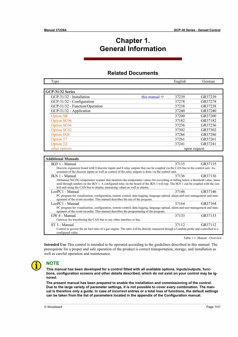
Related Documents Type English German GCP-31/32 Series GCP-31/32 - Installation this manual 37239 GR37239 GCP-31/32 - Configuration 37278 GR37278 GCP-31/32 - Function/Operation 37238 GR37238 GCP-31/32 - Application 37240 GR37240 Option SB 37200 GR37200 Option SC06 37182 GR37182 Option SC04 37236 GR37236 Option SC02 37302 GR37302 Option D08 37286 GR37286 Option T7 37261 GR37261 Option TZ 37241 GR37241 other options upon request Additional Manuals IKD 1 - Manual 37135 GR37135 Discrete expansion board with 8 discrete inputs and 8 relay outputs that can be coupled via the CAN bus to the control unit. As-
sessment of the discrete inputs as well as control of the relay outputs is done via the control unit. IKN 1 - Manual 37136 GR37136 20channel NiCrNi temperature scanner that monitors the temperature values for exceeding or falling below a threshold value, meas-
ured through senders on the IKN 1. A configured relay on the board of the IKN 1 will trip. The IKN 1 can be coupled with the con-trol unit using the CAN bus to display measuring values as well as alarms.
LeoPC1 - Manual 37146 GR37146 PC program for visualization, configuration, remote control, data logging, language upload, alarm and user management and man-
agement of the event recorder. This manual describes the use of the program. LeoPC1 - Manual 37164 GR37164 PC program for visualization, configuration, remote control, data logging, language upload, alarm and user management and man-
agement of the event recorder. This manual describes the programming of the program. GW 4 - Manual 37133 GR37133 Gateway for transferring the CAN bus to any other interface or bus.
ST 3 - Manual 37112 GR37112 Control to govern the air fuel ratio of a gas engine. The ratio will be directly measured though a Lambda probe and controlled to a
configured value.
Table 1-1: Manual - Overview
Intended Use This control is intended to be operated according to the guidelines described in this manual. The prerequisite for a proper and safe operation of the product is correct transportation, storage, and installation as well as careful operation and maintenance.
NOTE This manual has been developed for a control fitted with all available options. Inputs/outputs, func-tions, configuration screens and other details described, which do not exist on your control may be ig-nored. The present manual has been prepared to enable the installation and commissioning of the control. Due to the large variety of parameter settings, it is not possible to cover every combination. The man-ual is therefore only a guide. In case of incorrect entries or a total loss of functions, the default settings can be taken from the list of parameters located in the appendix of the Configuration manual.

Manual 37239A GCP-30 Series - Genset Control
Page 8/47 © Woodward
Chapter 2. Electrostatic Discharge Awareness
All electronic equipment is static-sensitive, some components more than others. To protect these components from static damage, you must take special precautions to minimize or eliminate electrostatic discharges. Follow these precautions when working with or near the control. 1. Before doing maintenance on the electronic control, discharge the static electricity on your body to
ground by touching and holding a grounded metal object (pipes, cabinets, equipment, etc.). 2. Avoid the build-up of static electricity on your body by not wearing clothing made of synthetic materials.
Wear cotton or cotton-blend materials as much as possible because these do not store static electric charges as much as synthetics.
3. Keep plastic, vinyl, and Styrofoam materials (such as plastic or Styrofoam cups, cup holders, cigarette
packages, cellophane wrappers, vinyl books or folders, plastic bottles, and plastic ash trays) away from the control, the modules, and the work area as much as possible.
4. Opening the Control unit will void the warranty!
Do not remove the printed circuit board (PCB) from the control cabinet unless absolutely necessary. If you must remove the PCB from the control cabinet, follow these precautions:
• Make sure that the unit is completely de-energized (all connectors have to be pulled off).
• Do not touch any part of the PCB except the edges.
• Do not touch the electrical conductors, connectors, or components with conductive devices or with
bare hands.
• When replacing a PCB, keep the new PCB in the plastic antistatic protective bag it comes in until you are ready to install it. Immediately after removing the old PCB from the control unit, place it in the antistatic protective bag.
WARNING To prevent damage to electronic components caused by improper handling, read and observe the pre-cautions in Woodward manual 82715, Guide for Handling and Protection of Electronic Controls, Printed Circuit Boards, and Modules.
Manual 37239A GCP-30 Series - Genset Control
© Woodward Page 9/47
Chapter 3. Housing
Dimensions ≡≡≡≡≡≡≡≡≡≡≡≡≡≡≡≡≡≡≡≡≡≡≡≡≡
136,0 mm
1
50
9990 93
83
Y1 Y5
48
105 111
X5X1 120
8,0 mm
111,0 mm
136,
0 m
m
54
24
60
25
144,
0 m
m
32,0 mm
42,0
mm
144,
0 m
m
12,0 mm
2004-02-11 | GCP30 Dimensions g2ww-0704-ab.skf
128
113
0
114
Configuration plug
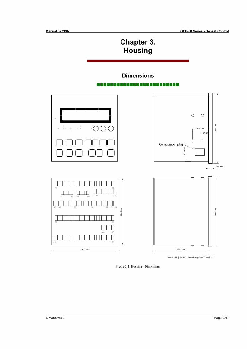
Figure 3-1: Housing - Dimensions
Manual 37239A GCP-30 Series - Genset Control
Page 10/47 © Woodward
Panel Cut-Out ≡≡≡≡≡≡≡≡≡≡≡≡≡≡≡≡≡≡≡≡≡≡≡≡≡
h' h H
bB
b'
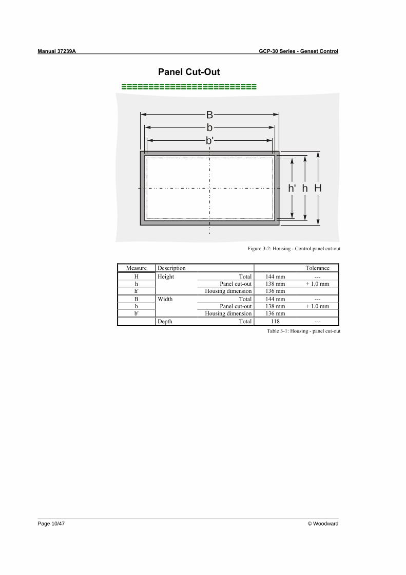
Figure 3-2: Housing - Control panel cut-out
Measure Description Tolerance
H Height Total 144 mm --- h Panel cut-out 138 mm + 1.0 mm h' Housing dimension 136 mm B Width Total 144 mm --- b Panel cut-out 138 mm + 1.0 mm b' Housing dimension 136 mm Depth Total 118 ---
Table 3-1: Housing - panel cut-out
Manual 37239A GCP-30 Series - Genset Control
© Woodward Page 11/47
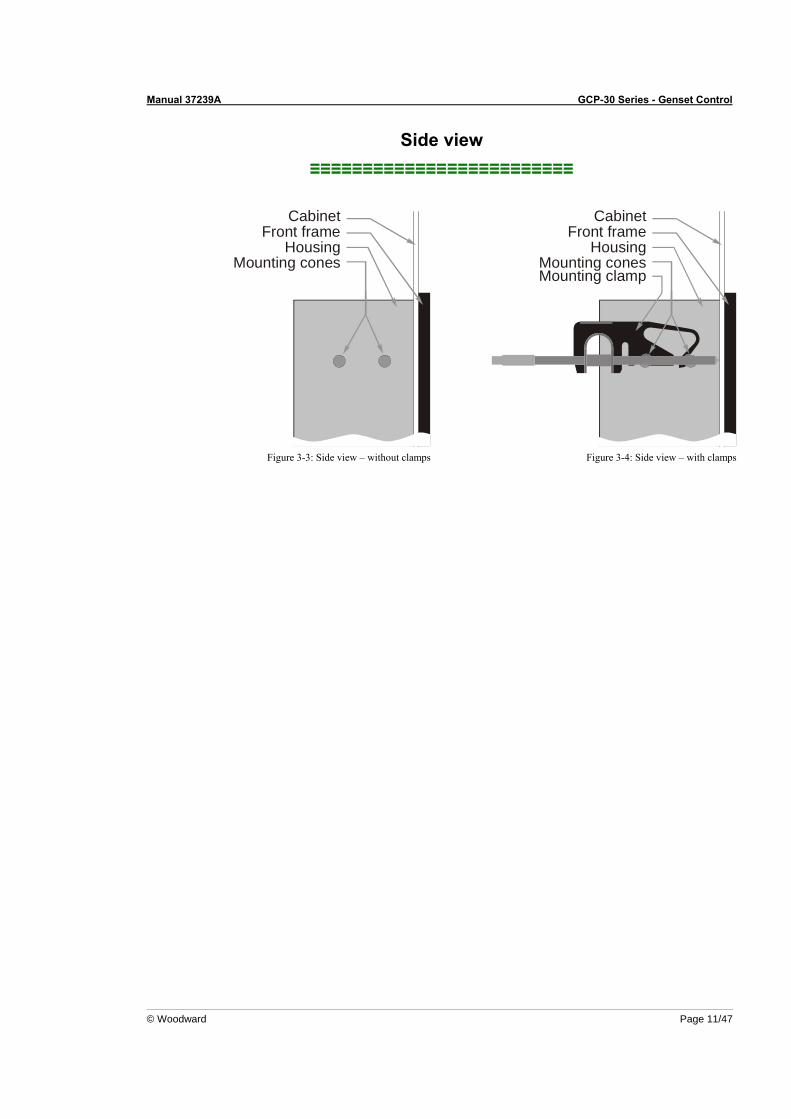
Side view ≡≡≡≡≡≡≡≡≡≡≡≡≡≡≡≡≡≡≡≡≡≡≡≡≡
CabinetFront frame
HousingMounting cones
Figure 3-3: Side view – without clamps
Cabinet
Front frameHousing
Mounting conesMounting clamp
Figure 3-4: Side view – with clamps
Manual 37239A GCP-30 Series - Genset Control
Page 12/47 © Woodward
Installation ≡≡≡≡≡≡≡≡≡≡≡≡≡≡≡≡≡≡≡≡≡≡≡≡≡
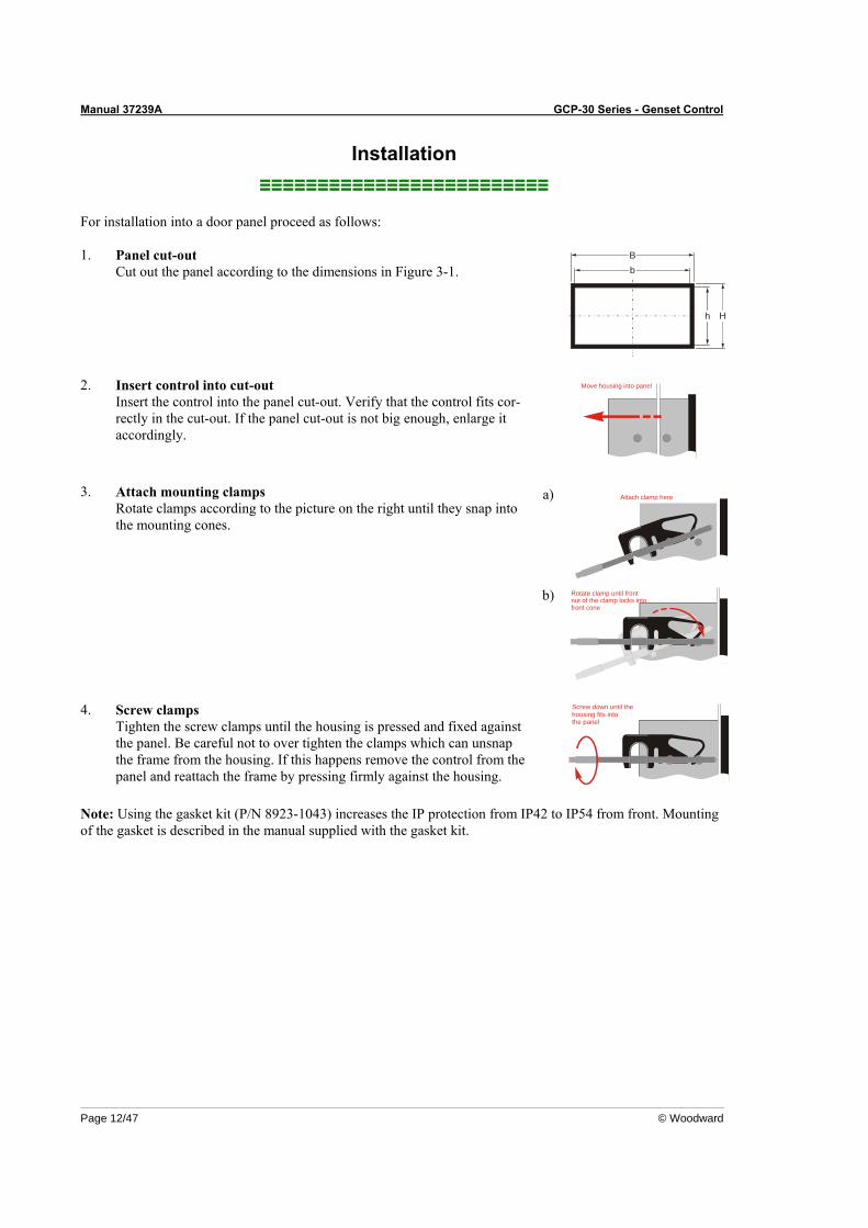
For installation into a door panel proceed as follows: 1. Panel cut-out
Cut out the panel according to the dimensions in Figure 3-1.
b
h H
B
2. Insert control into cut-out
Insert the control into the panel cut-out. Verify that the control fits cor-rectly in the cut-out. If the panel cut-out is not big enough, enlarge it accordingly.
Move housing into panel
a) Attach clamp here3. Attach mounting clamps
Rotate clamps according to the picture on the right until they snap into the mounting cones.
b) Rotate clamp until frontnut of the clamp locks intofront cone
4. Screw clamps
Tighten the screw clamps until the housing is pressed and fixed against the panel. Be careful not to over tighten the clamps which can unsnap the frame from the housing. If this happens remove the control from the panel and reattach the frame by pressing firmly against the housing.
Screw down until thehousing fits into the panel
Note: Using the gasket kit (P/N 8923-1043) increases the IP protection from IP42 to IP54 from front. Mounting of the gasket is described in the manual supplied with the gasket kit.

Manual 37239A GCP-30 Series - Genset Control
© Woodward Page 13/47
Chapter 4. Wiring Diagrams - Overview
WARNING A circuit breaker must be located near to the control and in a position easily accessible to the operator. This must also bear a sign identifying it as an isolating switch for the control.
NOTE Connected inductances (e.g. operating current coils, undervoltage tripping devices, auxiliary contac-tors, and/or power contactors) must be wired with an appropriate interference protection.
Manual 37239A GCP-30 Series - Genset Control
Page 14/47 © Woodward
GCP-31/BPD Package
CAN-L
G
5
9
6
7
8
A
B
C
D
E
F
G
2324
4114
154
2526
4229
3031
3220
2122
1112
138
910
X1X2
X3X4
X5
6263
6465
6667
6869
7071
7273
1819
4344
4546
7475
7677
7879
8081
8283
9091
92
L1
L2
s2 (l)
s1 (k)
s2 (l)
s1 (k)
s2 (l)
s1 (k)
Pickup
up to
13
addi
tiona
lge
nset
s (e
ach
via
one
GC
P-30
)
GAT
EWAY
GW
4(m
odem
)
Cont
rol r
oom
SPS
PC
Drive
GC
B
Reply: GCB is open
Readiness for operation
Alarm input 5 orCrank terminate
Alarm input 6 orMode selection locked
Alarm input 7 orBreaker logic
Alarm input 8
Alarm input 9
Alarm input 10 or'GCB close' without 'eng.mon.'
Alarm input 11 orblock emergency operation
Alarm input 12
Alarm input 13 or'Idle mode'
Alarm input 14
Alarm input 15
Alarm input 16
Start relay / Gas valve
Starter
Relay 1
Relay 2
Relay 3
Relay 4
Relay 5
Command: open GCB
Generator current L1
Generator current L2
Generator current L3
Generator voltage L1
Generator voltage L2
Generator voltage L3
Command: close GCB
The
sock
et fo
r the
PC
con
figur
atio
n is
situ
ated
on
the
side
of th
e un
it. T
his
is w
here
the
DPC
has
to b
e pl
ugge
d in
.
CAN bus interfaceGuidance level
GND
switching/inductive
GND
CAN-H
Termination
Relay 6
3837
Relay 7
4847
Standard =Ignition / preglow
Standard =Centralized alarm
Busbar voltage#1NO/
NC
#1NO/NC
#1NO/NC
#1NO/NC
#1NO/NC
#1NO/NC
#1NO/NC
#1NO/NC
#1NO/NC
#1NO/NC
#1NO/NC
#1NO/NC
P/N8440-15488440-15498440-15508440-1551
Package GCP-31/BPD
NameGCP-3111B/BPDGCP-3141B/BPDGCP-3115B/BPDGCP-3145B/BPD
PT; CT120 Vac; ../1 A400 Vac; ../1 A120 Vac; ../5 A400 Vac; ../5 A
3/(4
) 3
s1 (K) s1 (k)
s2 (L) s2 (l)
s1 (K)
s2 (L) s2 (l)
s1 (K) s1 (k)
s2 (L) s2 (l)
s1 (k)
L2
L1
L3
2
VOLTAGE / POW. FAC.(three-position controller)
raise
lower
raise
lower
SPEED / POWER(three-position controller)
Common = terminal 7
Mains current L1
0 Vdc
2004-08-26 | GCP30 Wiring Diagram g2ww-3504-aq.skf
2
1
4
3
5051
5227
2853
540 1
23
56
733
3435
3660
61
s2 (l)
s1 (k)
12/24 VdcNSubject to technical mocifications.
Mains voltage L1
Mains voltage L3
Mains voltage L2 Automatic 1
Automatic 2
Multi function terminal
Common (terminal 3/4/5/6/53/54)
Common
Alarm input 1(at sprinkler: emergency stop)
Alarm input 2
Alarm input 3
Common
Alarm input 4
conf
igur
able
dur
ing
setu
p (N
O/N
C)#1
#1
Batte
ry o
r ano
ther
pow
er s
uppl
y; te
rmin
al 7
/33/
60 is
pos
. or n
eg. s
igna
l#2
NO/NC
Isolated operation
Meaning Terminal 54 Terminal 53
Isolated operation YES (e.g. 24 Vdc) NO (e.g. 0 Vdc)
Mains parallel operation NO (e.g. 0 Vdc) YES (e.g. 24 Vdc)
Battery#2
#2Battery
Battery#2
#1NO/NC
#1NO/NC
#1NO/NC
#1NO/NC
#1NO/NC
#1NO/NC
starting firmware version 4.2xxx
GCP
-31/
BPD3/
(4)
3
s1 (K) s1 (k)
s2 (L) s2 (l)L1
Com
mon
=te
rmin
al 7
Mains parallel operationwith MCB "EXTERNAL"
Reply of the MCB(closed = NO,e.g. 0Vdc)
- MCB is to be closed: YES (e.g. 24 Vdc)- MCB is not to be closed: YES (e.g. 24 Vdc)
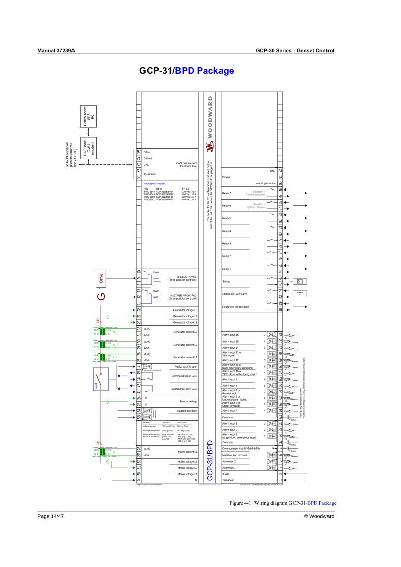
Figure 4-1: Wiring diagram GCP-31/BPD Package
Manual 37239A GCP-30 Series - Genset Control
© Woodward Page 15/47
GCP-31/BPQ Package
Mains current L1
CAN-L
G
5
0 Vdc
2004-08-26 | GCP30 Wiring Diagram g2ww-3504-aq.skf
2
1
4
3
9
6
7
8
A
B
C
D
E
F
G
5051
5227
2853
5423
2441
1415
425
2642
2930
3132
2021
2211
1213
89
10X1
X2X3
X4X5
0 12
35
67
3334
3536
6061
6263
6465
6667
6869
7071
7273
1819
4344
4546
7475
7677
7879
8081
8283
9091
92
s2 (l)
s1 (k)
L1
L2
s2 (l)
s1 (k)
s2 (l)
s1 (k)
s2 (l)
s1 (k)
12/24 VdcN
Pickup
up to
13
addi
tiona
lge
nset
s (e
ach
via
one
GC
P-30
)
GAT
EWAY
GW
4(m
odem
)
Cont
rol r
oom
SPS
PC
Drive
Subject to technical mocifications.
Mains voltage L1
Mains voltage L3
Mains voltage L2
GC
B
Reply: GCB is open
Automatic 1
Readiness for operation
Automatic 2
Multi function terminal
Common (terminal 3/4/5/6/53/54)
Common
Alarm input 1(at sprinkler: emergency stop)
Alarm input 2
Alarm input 3
Common
Alarm input 4
Alarm input 5 orCrank terminate
Alarm input 6 orMode selection locked
Alarm input 7 orBreaker logic
Alarm input 8
Alarm input 9
Alarm input 10 or'GCB close' without 'eng.mon.'
Alarm input 11 orblock emergency operation
Alarm input 12
Alarm input 13 or'Idle mode'
Alarm input 14
Alarm input 15
Alarm input 16
Start relay / Gas valve
Starter
Relay 1
Relay 2
Relay 3
Relay 4
Relay 5
Command: open GCB
Generator current L1
Generator current L2
Generator current L3
Generator voltage L1
Generator voltage L2
Generator voltage L3
Command: close GCB
The
sock
et fo
r the
PC
con
figur
atio
n is
situ
ated
on
the
side
of th
e un
it. T
his
is w
here
the
DPC
has
to b
e pl
ugge
d in
.
CAN bus interfaceGuidance level
GND
switching/inductive
GND
CAN-H
Termination
Relay 6
3837
Relay 7
4847
Standard =Ignition / preglow
Standard =Centralized alarm
conf
igur
able
dur
ing
setu
p (N
O/N
C)#1
#1
Batte
ry o
r ano
ther
pow
er s
uppl
y; te
rmin
al 7
/33/
60 is
pos
. or n
eg. s
igna
l#2
NO/NC
Isolated operation
Meaning Terminal 54 Terminal 53
Isolated operation YES (e.g. 24 Vdc) NO (e.g. 0 Vdc)
Mains parallel operation NO (e.g. 0 Vdc) YES (e.g. 24 Vdc)
Busbar voltage
Battery#2
#2Battery
Battery#2
#1NO/NC
#1NO/NC
#1NO/NC
#1NO/NC
#1NO/NC
#1NO/NC
#1NO/NC
#1NO/NC
#1NO/NC
#1NO/NC
#1NO/NC
#1NO/NC
#1NO/NC
#1NO/NC
#1NO/NC
#1NO/NC
#1NO/NC
#1NO/NC
starting firmware version 4.2xxx
3/(4
) 3
s1 (K) s1 (k)
s2 (L) s2 (l)
s1 (K)
s2 (L) s2 (l)
s1 (K) s1 (k)
s2 (L) s2 (l)
s1 (k)
L2
L1
L3
3/(4
)
3
s1 (K) s1 (k)
s2 (L) s2 (l)L1
2
GCP
-31/
BPQ
P/N8440-16078440-16088440-16098440-1610
Package GCP-31/BPQ
NameGCP-3111B/BPQGCP-3141B/BPQGCP-3115B/BPQGCP-3145B/BPQ
PT; CT120 Vac; ../1 A400 Vac; ../1 A120 Vac; ../5 A400 Vac; ../5 A
PWM
quas
i-con
tinuo
us c
ontro
ller
with
ana
log
outp
uts
(thre
e-po
sitio
nco
ntro
ller v
ia re
lay
man
ager
;ex
t. R/
C c
onne
ctio
n!)
DC
curre
nt
DC
volta
ge
PWM
SPEED / POWER(analog controller output)
VOLTAGE / POW. FAC.(analog controller output)
GND
GND
GND
PWM
UA
N/C
I A
GND
UA
GND
N/C
I A
Com
mon
=te
rmin
al 7
Common = terminal 7
Mains parallel operationwith MCB "EXTERNAL"
Reply of the MCB(closed = NO,e.g. 0Vdc)
- MCB is to be closed: YES (e.g. 24 Vdc)- MCB is not to be closed: YES (e.g. 24 Vdc)
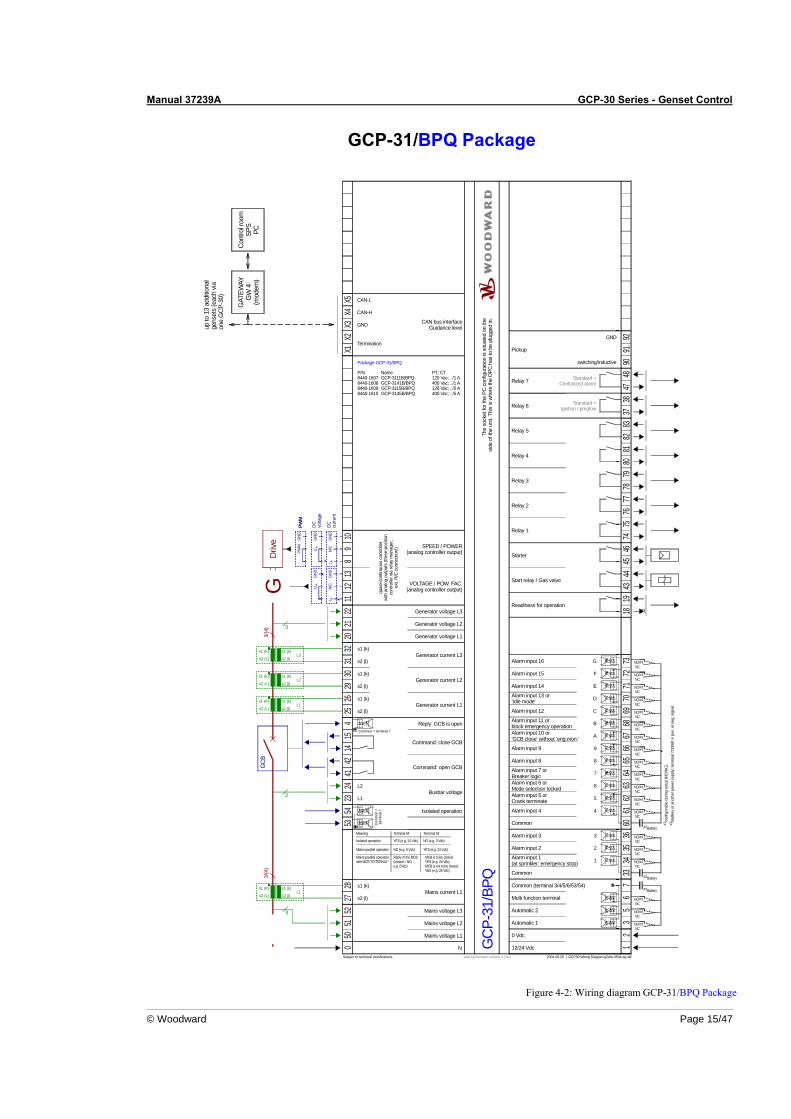
Figure 4-2: Wiring diagram GCP-31/BPQ Package

Manual 37239A GCP-30 Series - Genset Control
Page 16/47 © Woodward
GCP-31/XPD Package
Mains current L1
CAN-L
G
5
0 Vdc
2004-08-26 | GCP30 Wiring Diagram g2ww-3504-aq.skf
2
1
4
3
9
6
7
8
A
B
C
D
E
F
G
5051
5227
2853
5423
2441
1415
425
2642
2930
3132
2021
2211
1213
89
10X1
X2X3
X4X5
0 12
35
67
3334
3536
6061
6263
6465
6667
6869
7071
7273
1819
4344
4546
7475
7677
7879
8081
8283
9091
92
s2 (l)
s1 (k)
L1
L2
s2 (l)
s1 (k)
s2 (l)
s1 (k)
s2 (l)
s1 (k)
12/24 VdcN
Pickup
up to
13
addi
tiona
lge
nset
s (e
ach
via
one
GC
P-30
)
GAT
EWAY
GW
4(m
odem
)
Cont
rol r
oom
SPS
PC
Drive
Subject to technical mocifications.
Mains voltage L1
Mains voltage L3
Mains voltage L2
GC
B
Reply: GCB is open
Automatic 1
Readiness for operation
Automatic 2
Multi function terminal
Common (terminal 3/4/5/6/53/54)
Common
Alarm input 1(at sprinkler: emergency stop)
Alarm input 2
Alarm input 3
Common
Alarm input 4
Alarm input 5 orCrank terminate
Alarm input 6 orMode selection locked
Alarm input 7 orBreaker logic
Alarm input 8
Alarm input 9
Alarm input 10 or'GCB close' without 'eng.mon.'
Alarm input 11 orblock emergency operation
Alarm input 12
Alarm input 13 or'Idle mode'
Alarm input 14
Alarm input 15
Alarm input 16
Start relay / Gas valve
Starter
Relay 1
Relay 2
Relay 3
Relay 4
Relay 5
Command: open GCB
Generator current L1
Generator current L2
Generator current L3
Generator voltage L1
Generator voltage L2
Generator voltage L3
Command: close GCB
The
sock
et fo
r the
PC
con
figur
atio
n is
situ
ated
on
the
side
of th
e un
it. T
his
is w
here
the
DPC
has
to b
e pl
ugge
d in
.
CAN bus interfaceGuidance level
GND
switching/inductive
GND
CAN-H
Termination
Relay 6
3837
Relay 7
4847
Standard =Ignition / preglow
Standard =Centralized alarm
conf
igur
able
dur
ing
setu
p (N
O/N
C)#1
#1
Batte
ry o
r ano
ther
pow
er s
uppl
y; te
rmin
al 7
/33/
60 is
pos
. or n
eg. s
igna
l#2
NO/NC
Isolated operation
Meaning Terminal 54 Terminal 53
Isolated operation YES (e.g. 24 Vdc) NO (e.g. 0 Vdc)
Mains parallel operation NO (e.g. 0 Vdc) YES (e.g. 24 Vdc)
Busbar voltage
Battery#2
#2Battery
Battery#2
#1NO/NC
#1NO/NC
#1NO/NC
#1NO/NC
#1NO/NC
#1NO/NC
#1NO/NC
#1NO/NC
#1NO/NC
#1NO/NC
#1NO/NC
#1NO/NC
#1NO/NC
#1NO/NC
#1NO/NC
#1NO/NC
#1NO/NC
#1NO/NC
starting firmware version 4.2xxx
GCP
-31/
XPD
Package GCP-31/XPD
P/N8440-15528440-15538440-15548440-1555
NameGCP-3111B/XPDGCP-3141B/XPDGCP-3115B/XPDGCP-3145B/XPD
PT; CT120 Vac; ../1 A400 Vac; ../1 A120 Vac; ../5 A400 Vac; ../5 A
3/(4
) 3
s1 (K) s1 (k)
s2 (L) s2 (l)
s1 (K)
s2 (L) s2 (l)
s1 (K) s1 (k)
s2 (L) s2 (l)
s1 (k)
L2
L1
L3
3/(4
)
3
s1 (K) s1 (k)
s2 (L) s2 (l)L1
2
VOLTAGE / POW. FAC.(three-position controller)
raise
lower
raise
lower
SPEED / POWER(three-position controller)
105
106
107
108
109
110111
112113
120
121
122
123
9394
9596
9798
9910
010
110
210
310
4
GND
GND
AI
AI
Anal
og o
utpu
tm
anag
er
Analog output0/4-20 mA
Analog input 1 [T1]0/4-20 mA
Analog input 2 [T2]0/4-20 mA
Analog input 3 [T3]0/4-20 mA
Analog input 4 [T4]Pt100
Analog input 5 [T5]Pt100
Analog input 7 [T7]VDO Temperature 30-120 °C (0-380 Ohm)
or alternatively 86-248 °F (0-380 Ohm)
Analog input 6 [T6]VDO Pressure 0-5/10 bar (0-180 Ohm)
or alternatively 0-72.5/145 psi (0-180 Ohm)
max
. 8x
LS 4
Com
mon
=te
rmin
al 7
Common = terminal 7
Mains parallel operationwith MCB "EXTERNAL"
Reply of the MCB(closed = NO,e.g. 0Vdc)
- MCB is to be closed: YES (e.g. 24 Vdc)- MCB is not to be closed: YES (e.g. 24 Vdc)
124
127
128
Common
Operation mode STOP
Operation mode AUTOMATIC #1NO/NC
#1NO/NC
Battery#2
Figure 4-3: Wiring diagram GCP-31/XPD Package
Manual 37239A GCP-30 Series - Genset Control
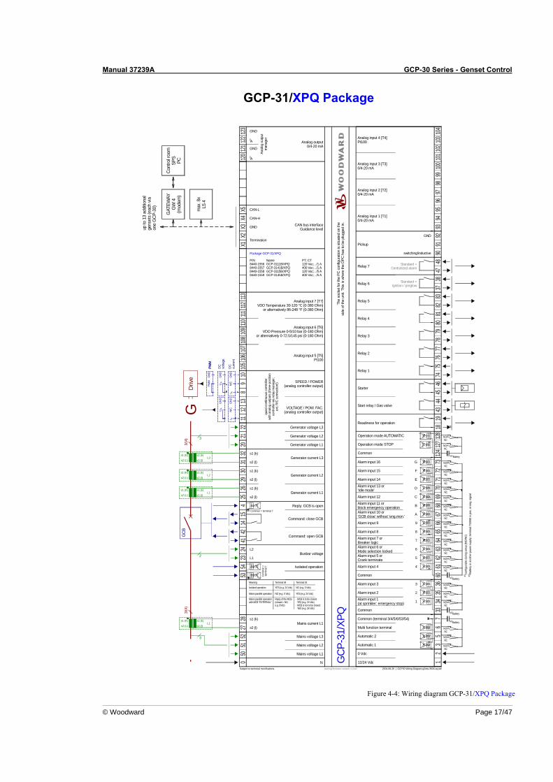
© Woodward Page 17/47
GCP-31/XPQ Package
Mains current L1
CAN-L
G
5
0 Vdc
2004-08-26 | GCP30 Wiring Diagram g2ww-3504-aq.skf
2
1
4
3
9
6
7
8
A
B
C
D
E
F
G
5051
5227
2853
5423
2441
1415
425
2642
2930
3132
2021
2211
1213
89
10X1
X2X3
X4X5
0 12
35
67
3334
3536
6061
6263
6465
6667
6869
7071
7273
1819
4344
4546
7475
7677
7879
8081
8283
9091
92
s2 (l)
s1 (k)
L1
L2
s2 (l)
s1 (k)
s2 (l)
s1 (k)
s2 (l)
s1 (k)
12/24 VdcN
Pickup
up to
13
addi
tiona
lge
nset
s (e
ach
via
one
GC
P-30
)
GAT
EWAY
GW
4(m
odem
)
Cont
rol r
oom
SPS
PC
Drive
Subject to technical mocifications.
Mains voltage L1
Mains voltage L3
Mains voltage L2
GC
B
Reply: GCB is open
Automatic 1
Readiness for operation
Automatic 2
Multi function terminal
Common (terminal 3/4/5/6/53/54)
Common
Alarm input 1(at sprinkler: emergency stop)
Alarm input 2
Alarm input 3
Common
Alarm input 4
Alarm input 5 orCrank terminate
Alarm input 6 orMode selection locked
Alarm input 7 orBreaker logic
Alarm input 8
Alarm input 9
Alarm input 10 or'GCB close' without 'eng.mon.'
Alarm input 11 orblock emergency operation
Alarm input 12
Alarm input 13 or'Idle mode'
Alarm input 14
Alarm input 15
Alarm input 16
Start relay / Gas valve
Starter
Relay 1
Relay 2
Relay 3
Relay 4
Relay 5
Command: open GCB
Generator current L1
Generator current L2
Generator current L3
Generator voltage L1
Generator voltage L2
Generator voltage L3
Command: close GCB
The
sock
et fo
r the
PC
con
figur
atio
n is
situ
ated
on
the
side
of th
e un
it. T
his
is w
here
the
DPC
has
to b
e pl
ugge
d in
.
CAN bus interfaceGuidance level
GND
switching/inductive
GND
CAN-H
Termination
Relay 6
3837
Relay 7
4847
Standard =Ignition / preglow
Standard =Centralized alarm
conf
igur
able
dur
ing
setu
p (N
O/N
C)#1
#1
Batte
ry o
r ano
ther
pow
er s
uppl
y; te
rmin
al 7
/33/
60 is
pos
. or n
eg. s
igna
l#2
NO/NC
Isolated operation
Meaning Terminal 54 Terminal 53
Isolated operation YES (e.g. 24 Vdc) NO (e.g. 0 Vdc)
Mains parallel operation NO (e.g. 0 Vdc) YES (e.g. 24 Vdc)
Busbar voltage
Battery#2
#2Battery
Battery#2
#1NO/NC
#1NO/NC
#1NO/NC
#1NO/NC
#1NO/NC
#1NO/NC
#1NO/NC
#1NO/NC
#1NO/NC
#1NO/NC
#1NO/NC
#1NO/NC
#1NO/NC
#1NO/NC
#1NO/NC
#1NO/NC
#1NO/NC
#1NO/NC
starting firmware version 4.2xxx
GCP
-31/
XPQ
3/(4
) 3
s1 (K) s1 (k)
s2 (L) s2 (l)
s1 (K)
s2 (L) s2 (l)
s1 (K) s1 (k)
s2 (L) s2 (l)
s1 (k)
L2
L1
L3
3/(4
)
3
s1 (K) s1 (k)
s2 (L) s2 (l)L1
2
PWM
quas
i-con
tinuo
us c
ontro
ller
with
ana
log
outp
uts
(thre
e-po
sitio
nco
ntro
ller v
ia re
lay
man
ager
;ex
t. R/
C c
onne
ctio
n!)
DC
curre
nt
DC
volta
ge
PWM
SPEED / POWER(analog controller output)
VOLTAGE / POW. FAC.(analog controller output)
GND
GND
GND
PWM
UA
N/C
I A
GND
UA
GND
N/C
I A
max
. 8x
LS 4
Package GCP-31/XPQ
P/N8440-15568440-15578440-15588440-1559
NameGCP-3111B/XPQGCP-3141B/XPQGCP-3115B/XPQGCP-3145B/XPQ
PT; CT120 Vac; ../1 A400 Vac; ../1 A120 Vac; ../5 A400 Vac; ../5 A
105
106
107
108
109
110111
112113
120
121
122
123
9394
9596
9798
9910
010
110
210
310
4
GND
GND
AI
AI
Anal
og o
utpu
tm
anag
er
Analog output0/4-20 mA
Analog input 1 [T1]0/4-20 mA
Analog input 2 [T2]0/4-20 mA
Analog input 3 [T3]0/4-20 mA
Analog input 4 [T4]Pt100
Analog input 5 [T5]Pt100
Analog input 7 [T7]VDO Temperature 30-120 °C (0-380 Ohm)
or alternatively 86-248 °F (0-380 Ohm)
Analog input 6 [T6]VDO Pressure 0-5/10 bar (0-180 Ohm)
or alternatively 0-72.5/145 psi (0-180 Ohm)
Com
mon
=te
rmin
al 7
Common = terminal 7
Mains parallel operationwith MCB "EXTERNAL"
Reply of the MCB(closed = NO,e.g. 0Vdc)
- MCB is to be closed: YES (e.g. 24 Vdc)- MCB is not to be closed: YES (e.g. 24 Vdc)
124
127
128
#1NO/NC
#1NO/NC
#2Common
Operation mode STOP
Operation mode AUTOMATIC
Battery
Figure 4-4: Wiring diagram GCP-31/XPQ Package
Manual 37239A GCP-30 Series - Genset Control
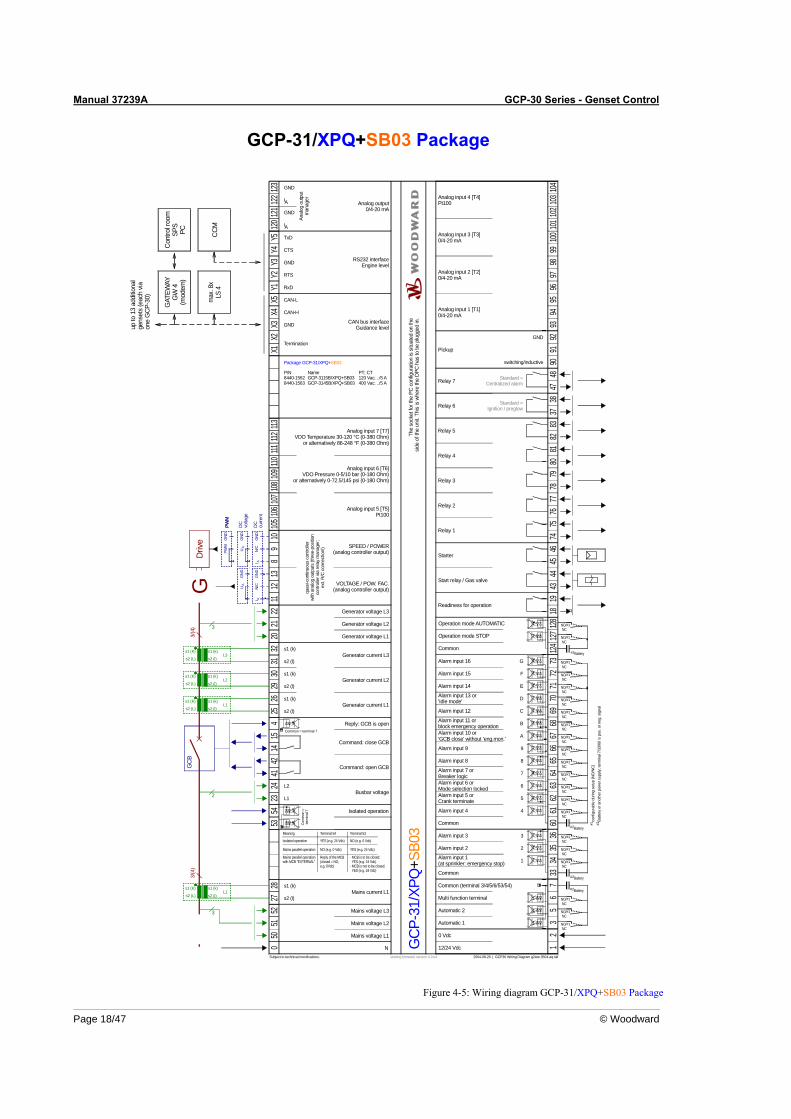
Page 18/47 © Woodward
GCP-31/XPQ+SB03 Package
Mains current L1
CAN-L
G
5
0 Vdc
2004-08-26 | GCP30 Wiring Diagram g2ww-3504-aq.skf
2
1
4
3
9
6
7
8
A
B
C
D
E
F
G
5051
5227
2853
5423
2441
1415
425
2642
2930
3132
2021
2211
1213
89
10X1
X2X3
X4X5
0 12
35
67
3334
3536
6061
6263
6465
6667
6869
7071
7273
1819
4344
4546
7475
7677
7879
8081
8283
9091
92
s2 (l)
s1 (k)
L1
L2
s2 (l)
s1 (k)
s2 (l)
s1 (k)
s2 (l)
s1 (k)
12/24 VdcN
Pickup
up to
13
addi
tiona
lge
nset
s (e
ach
via
one
GC
P-30
)
GAT
EWAY
GW
4(m
odem
)
Cont
rol r
oom
SPS
PC
Drive
Subject to technical mocifications.
Mains voltage L1
Mains voltage L3
Mains voltage L2
GC
B
Reply: GCB is open
Automatic 1
Readiness for operation
Automatic 2
Multi function terminal
Common (terminal 3/4/5/6/53/54)
Common
Alarm input 1(at sprinkler: emergency stop)
Alarm input 2
Alarm input 3
Common
Alarm input 4
Alarm input 5 orCrank terminate
Alarm input 6 orMode selection locked
Alarm input 7 orBreaker logic
Alarm input 8
Alarm input 9
Alarm input 10 or'GCB close' without 'eng.mon.'
Alarm input 11 orblock emergency operation
Alarm input 12
Alarm input 13 or'Idle mode'
Alarm input 14
Alarm input 15
Alarm input 16
Start relay / Gas valve
Starter
Relay 1
Relay 2
Relay 3
Relay 4
Relay 5
Command: open GCB
Generator current L1
Generator current L2
Generator current L3
Generator voltage L1
Generator voltage L2
Generator voltage L3
Command: close GCB
The
sock
et fo
r the
PC
con
figur
atio
n is
situ
ated
on
the
side
of th
e un
it. T
his
is w
here
the
DPC
has
to b
e pl
ugge
d in
.
CAN bus interfaceGuidance level
GND
switching/inductive
GND
CAN-H
Termination
Relay 6
3837
Relay 7
4847
Standard =Ignition / preglow
Standard =Centralized alarm
conf
igur
able
dur
ing
setu
p (N
O/N
C)#1
#1
Batte
ry o
r ano
ther
pow
er s
uppl
y; te
rmin
al 7
/33/
60 is
pos
. or n
eg. s
igna
l#2
NO/NC
Isolated operation
Meaning Terminal 54 Terminal 53
Isolated operation YES (e.g. 24 Vdc) NO (e.g. 0 Vdc)
Mains parallel operation NO (e.g. 0 Vdc) YES (e.g. 24 Vdc)
Busbar voltage
Battery#2
#2Battery
Battery#2
#1NO/NC
#1NO/NC
#1NO/NC
#1NO/NC
#1NO/NC
#1NO/NC
#1NO/NC
#1NO/NC
#1NO/NC
#1NO/NC
#1NO/NC
#1NO/NC
#1NO/NC
#1NO/NC
#1NO/NC
#1NO/NC
#1NO/NC
#1NO/NC
starting firmware version 4.2xxx
3/(4
) 3
s1 (K) s1 (k)
s2 (L) s2 (l)
s1 (K)
s2 (L) s2 (l)
s1 (K) s1 (k)
s2 (L) s2 (l)
s1 (k)
L2
L1
L3
3/(4
)
3
s1 (K) s1 (k)
s2 (L) s2 (l)L1
2
max
. 8x
LS 4
GCP
-31/
XPQ
+SB0
3
Package GCP-31/XPQ+SB03
P/N8440-15628440-1563
NameGCP-3115B/XPQ+SB03GCP-3145B/XPQ+SB03
PT; CT120 Vac; ../5 A400 Vac; ../5 A
PWM
quas
i-con
tinuo
us c
ontro
ller
with
ana
log
outp
uts
(thre
e-po
sitio
nco
ntro
ller v
ia re
lay
man
ager
;ex
t. R/
C c
onne
ctio
n!)
DC
curre
nt
DC
volta
ge
PWM
SPEED / POWER(analog controller output)
VOLTAGE / POW. FAC.(analog controller output)
GND
GND
GND
PWM
UA
N/C
I A
GND
UA
GND
N/C
I A
105
106
107
108
109
110111
112113
Y1Y2
Y3Y4
Y512
012
112
212
3
9394
9596
9798
9910
010
110
210
310
4
GND
GND
AI
AI
Anal
og o
utpu
tm
anag
er
RS232 interfaceEngine level
Analog output0/4-20 mA
GND
CTS
TxDCCM
Analog input 1 [T1]0/4-20 mA
Analog input 2 [T2]0/4-20 mA
Analog input 3 [T3]0/4-20 mA
Analog input 4 [T4]Pt100
Analog input 5 [T5]Pt100
Analog input 7 [T7]VDO Temperature 30-120 °C (0-380 Ohm)
or alternatively 86-248 °F (0-380 Ohm)
Analog input 6 [T6]VDO Pressure 0-5/10 bar (0-180 Ohm)
or alternatively 0-72.5/145 psi (0-180 Ohm)
RTS
RxD
Com
mon
=te
rmin
al 7
Common = terminal 7
Mains parallel operationwith MCB "EXTERNAL"
Reply of the MCB(closed = NO,e.g. 0Vdc)
- MCB is to be closed: YES (e.g. 24 Vdc)- MCB is not to be closed: YES (e.g. 24 Vdc)
124
127
128
#1NO/NC
#1NO/NC
#2Common
Operation mode STOP
Operation mode AUTOMATIC
Battery
Figure 4-5: Wiring diagram GCP-31/XPQ+SB03 Package
Manual 37239A GCP-30 Series - Genset Control
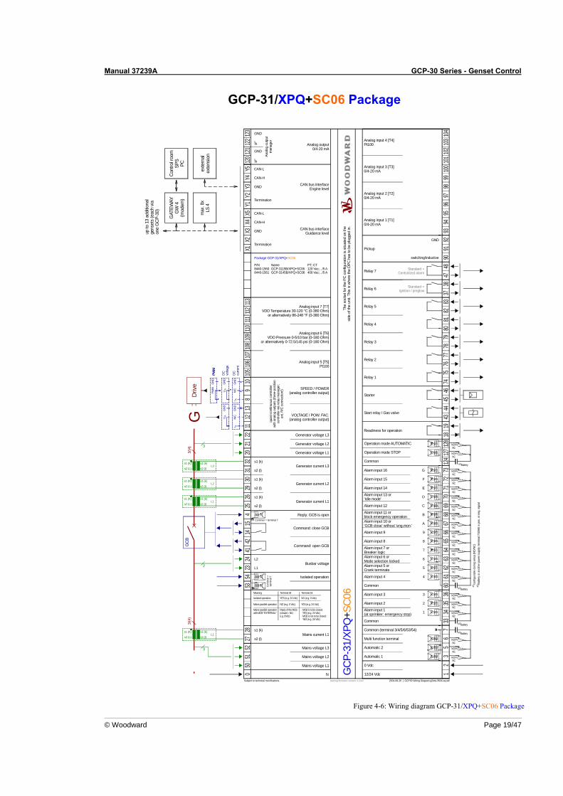
© Woodward Page 19/47
GCP-31/XPQ+SC06 Package
max
. 8x
LS 4
Mains current L1
CAN-L
G
5
0 Vdc
2004-08-26 | GCP30 Wiring Diagram g2ww-3504-aq.skf
2
1
4
3
9
6
7
8
A
B
C
D
E
F
G
5051
5227
2853
5423
2441
1415
425
2642
2930
3132
2021
2211
1213
89
10X1
X2X3
X4X5
0 12
35
67
3334
3536
6061
6263
6465
6667
6869
7071
7273
1819
4344
4546
7475
7677
7879
8081
8283
9091
92
s2 (l)
s1 (k)
L1
L2
s2 (l)
s1 (k)
s2 (l)
s1 (k)
s2 (l)
s1 (k)
12/24 VdcN
Pickup
up to
13
addi
tiona
lge
nset
s (e
ach
via
one
GC
P-30
)
GAT
EWAY
GW
4(m
odem
)
Cont
rol r
oom
SPS
PC
Drive
Subject to technical mocifications.
Mains voltage L1
Mains voltage L3
Mains voltage L2
GC
B
Reply: GCB is open
Automatic 1
Readiness for operation
Automatic 2
Multi function terminal
Common (terminal 3/4/5/6/53/54)
Common
Alarm input 1(at sprinkler: emergency stop)
Alarm input 2
Alarm input 3
Common
Alarm input 4
Alarm input 5 orCrank terminate
Alarm input 6 orMode selection locked
Alarm input 7 orBreaker logic
Alarm input 8
Alarm input 9
Alarm input 10 or'GCB close' without 'eng.mon.'
Alarm input 11 orblock emergency operation
Alarm input 12
Alarm input 13 or'Idle mode'
Alarm input 14
Alarm input 15
Alarm input 16
Start relay / Gas valve
Starter
Relay 1
Relay 2
Relay 3
Relay 4
Relay 5
Command: open GCB
Generator current L1
Generator current L2
Generator current L3
Generator voltage L1
Generator voltage L2
Generator voltage L3
Command: close GCB
The
sock
et fo
r the
PC
con
figur
atio
n is
situ
ated
on
the
side
of th
e un
it. T
his
is w
here
the
DPC
has
to b
e pl
ugge
d in
.
CAN bus interfaceGuidance level
GND
switching/inductive
GND
CAN-H
Termination
Relay 6
3837
Relay 7
4847
Standard =Ignition / preglow
Standard =Centralized alarm
conf
igur
able
dur
ing
setu
p (N
O/N
C)#1
#1
Batte
ry o
r ano
ther
pow
er s
uppl
y; te
rmin
al 7
/33/
60 is
pos
. or n
eg. s
igna
l#2
NO/NC
Isolated operation
Meaning Terminal 54 Terminal 53
Isolated operation YES (e.g. 24 Vdc) NO (e.g. 0 Vdc)
Mains parallel operation NO (e.g. 0 Vdc) YES (e.g. 24 Vdc)
Busbar voltage
Battery#2
#2Battery
Battery#2
#1NO/NC
#1NO/NC
#1NO/NC
#1NO/NC
#1NO/NC
#1NO/NC
#1NO/NC
#1NO/NC
#1NO/NC
#1NO/NC
#1NO/NC
#1NO/NC
#1NO/NC
#1NO/NC
#1NO/NC
#1NO/NC
#1NO/NC
#1NO/NC
starting firmware version 4.2xxx
GCP
-31/
XPQ
+SC0
6
Package GCP-31/XPQ+SC06
P/N8440-15608440-1561
NameGCP-3115B/XPQ+SC06GCP-3145B/XPQ+SC06
PT; CT120 Vac; ../5 A400 Vac; ../5 A
3/(4
) 3
s1 (K) s1 (k)
s2 (L) s2 (l)
s1 (K)
s2 (L) s2 (l)
s1 (K) s1 (k)
s2 (L) s2 (l)
s1 (k)
L2
L1
L3
3/(4
)
3
s1 (K) s1 (k)
s2 (L) s2 (l)L1
2
PWM
quas
i-con
tinuo
us c
ontro
ller
with
ana
log
outp
uts
(thre
e-po
sitio
nco
ntro
ller v
ia re
lay
man
ager
;ex
t. R/
C c
onne
ctio
n!)
DC
curre
nt
DC
volta
ge
PWM
SPEED / POWER(analog controller output)
VOLTAGE / POW. FAC.(analog controller output)
GND
GND
GND
PWM
UA
N/C
I A
GND
UA
GND
N/C
I A
105
106
107
108
109
110111
112113
Y1Y2
Y3Y4
Y512
012
112
212
3
9394
9596
9798
9910
010
110
210
310
4
GND
GND
AI
AI
Anal
og o
utpu
tm
anag
er
CAN bus interfaceEngine level
Analog output0/4-20 mA
GND
CAN-H
CAN-L
Terminationex
tern
alex
tens
ion
Analog input 1 [T1]0/4-20 mA
Analog input 2 [T2]0/4-20 mA
Analog input 3 [T3]0/4-20 mA
Analog input 4 [T4]Pt100
Analog input 5 [T5]Pt100
Analog input 7 [T7]VDO Temperature 30-120 °C (0-380 Ohm)
or alternatively 86-248 °F (0-380 Ohm)
Analog input 6 [T6]VDO Pressure 0-5/10 bar (0-180 Ohm)
or alternatively 0-72.5/145 psi (0-180 Ohm)
Com
mon
=te
rmin
al 7
Common = terminal 7
Mains parallel operationwith MCB "EXTERNAL"
Reply of the MCB(closed = NO,e.g. 0Vdc)
- MCB is to be closed: YES (e.g. 24 Vdc)- MCB is not to be closed: YES (e.g. 24 Vdc)
124
127
128
#1NO/NC
#1NO/NC
#2Common
Operation mode STOP
Operation mode AUTOMATIC
Battery
Figure 4-6: Wiring diagram GCP-31/XPQ+SC06 Package
Manual 37239A GCP-30 Series - Genset Control
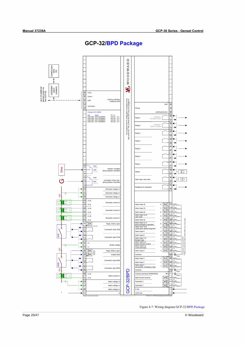
Page 20/47 © Woodward
GCP-32/BPD Package
17
VOLTAGE / POW. FAC.(three-position controller)
Mains current L1
CAN-L
G
5
0 Vdc
2004-08-26 | GCP30 Wiring Diagram g2ww-3504-aq.skf
2
1
4
3
9
6
7
8
A
B
C
D
E
F
G
5051
5227
2853
5423
2441
1415
425
2642
2930
3132
2021
2211
1213
89
10X1
X2X3
X4X5
0 12
35
67
3334
3536
6061
6263
6465
6667
6869
7071
7273
1819
4344
4546
7475
7677
7879
8081
8283
9091
92
s2 (l)
s1 (k)
L1
L2
s2 (l)
s1 (k)
s2 (l)
s1 (k)
s2 (l)
s1 (k)
12/24 VdcN
Pickup
up to
13
addi
tiona
lge
nset
s (e
ach
via
one
GC
P-30
)
GAT
EWAY
GW
4(m
odem
)
Cont
rol r
oom
SPS
PC
Drive
Subject to technical mocifications.
Mains voltage L1
Mains voltage L3
Mains voltage L2
GC
B
Reply: GCB is open
Automatic 1
Readiness for operation
Automatic 2
Multi function terminal
Common (terminal 3/4/5/6/53/54)
Common
Alarm input 1(at sprinkler: emergency stop)
Alarm input 2
Alarm input 3
Common
Alarm input 4
Alarm input 5 orCrank terminate
Alarm input 6 orMode selection locked
Alarm input 7 orBreaker logic
Alarm input 8
Alarm input 9
Alarm input 10 or'GCB close' without 'eng.mon.'
Alarm input 11 orblock emergency operation
Alarm input 12
Alarm input 13 or'Idle mode'
Alarm input 14
Alarm input 15
Alarm input 16
Start relay / Gas valve
Starter
Relay 1
Relay 2
Relay 3
Relay 4
Relay 5
Command: open GCB
Generator current L1
Generator current L2
Generator current L3
Generator voltage L1
Generator voltage L2
Generator voltage L3
Command: close GCB
The
sock
et fo
r the
PC
con
figur
atio
n is
situ
ated
on
the
side
of th
e un
it. T
his
is w
here
the
DPC
has
to b
e pl
ugge
d in
.
CAN bus interfaceGuidance level
GND
switching/inductive
GND
CAN-H
Termination
Relay 6
3837
Relay 7
4847
Standard =Ignition / preglow
Standard =Centralized alarm
conf
igur
able
dur
ing
setu
p (N
O/N
C)#1
#1
Batte
ry o
r ano
ther
pow
er s
uppl
y; te
rmin
al 7
/33/
60 is
pos
. or n
eg. s
igna
l#2
NO/NC
4016
39
MC
B
Reply: MCB is open
Command: close MCB
Enable MCB
Command: open MCB
Busbar voltage
raise
lower
raise
lower
Battery#2
#2Battery
Battery#2
#1NO/NC
#1NO/NC
#1NO/NC
#1NO/NC
#1NO/NC
#1NO/NC
#1NO/NC
#1NO/NC
#1NO/NC
#1NO/NC
#1NO/NC
#1NO/NC
#1NO/NC
#1NO/NC
#1NO/NC
#1NO/NC
#1NO/NC
#1NO/NC
starting firmware version 4.2xxx
GCP
-32/
BPD
Package GCP-32/BPD
P/N8440-15648440-15658440-15668440-1567
NameGCP-3211B/BPDGCP-3241B/BPDGCP-3215B/BPDGCP-3245B/BPD
PT; CT120 Vac; ../1 A400 Vac; ../1 A120 Vac; ../5 A400 Vac; ../5 A
SPEED / POWER(three-position controller)
3/(4
) 3
s1 (K) s1 (k)
s2 (L) s2 (l)
s1 (K)
s2 (L) s2 (l)
s1 (K) s1 (k)
s2 (L) s2 (l)
s1 (k)
L2
L1
L3
3/(4
)3/
(4)
3
s1 (K) s1 (k)
s2 (L) s2 (l)L1
2
Com
mon
=te
rmin
al 7
Common = terminal 7
Figure 4-7: Wiring diagram GCP-32/BPD Package
Manual 37239A GCP-30 Series - Genset Control
© Woodward Page 21/47
GCP-32/BPQ Package
17
Mains current L1
CAN-L
G
5
0 Vdc
2004-08-26 | GCP30 Wiring Diagram g2ww-3504-aq.skf
2
1
4
3
9
6
7
8
A
B
C
D
E
F
G
5051
5227
2853
5423
2441
1415
425
2642
2930
3132
2021
2211
1213
89
10X1
X2X3
X4X5
0 12
35
67
3334
3536
6061
6263
6465
6667
6869
7071
7273
1819
4344
4546
7475
7677
7879
8081
8283
9091
92
s2 (l)
s1 (k)
L1
L2
s2 (l)
s1 (k)
s2 (l)
s1 (k)
s2 (l)
s1 (k)
12/24 VdcN
Pickup
up to
13
addi
tiona
lge
nset
s (e
ach
via
one
GC
P-30
)
GAT
EWAY
GW
4(m
odem
)
Cont
rol r
oom
SPS
PC
Drive
Subject to technical mocifications.
Mains voltage L1
Mains voltage L3
Mains voltage L2
GC
B
Reply: GCB is open
Automatic 1
Readiness for operation
Automatic 2
Multi function terminal
Common (terminal 3/4/5/6/53/54)
Common
Alarm input 1(at sprinkler: emergency stop)
Alarm input 2
Alarm input 3
Common
Alarm input 4
Alarm input 5 orCrank terminate
Alarm input 6 orMode selection locked
Alarm input 7 orBreaker logic
Alarm input 8
Alarm input 9
Alarm input 10 or'GCB close' without 'eng.mon.'
Alarm input 11 orblock emergency operation
Alarm input 12
Alarm input 13 or'Idle mode'
Alarm input 14
Alarm input 15
Alarm input 16
Start relay / Gas valve
Starter
Relay 1
Relay 2
Relay 3
Relay 4
Relay 5
Command: open GCB
Generator current L1
Generator current L2
Generator current L3
Generator voltage L1
Generator voltage L2
Generator voltage L3
Command: close GCB
The
sock
et fo
r the
PC
con
figur
atio
n is
situ
ated
on
the
side
of th
e un
it. T
his
is w
here
the
DPC
has
to b
e pl
ugge
d in
.
CAN bus interfaceGuidance level
GND
switching/inductive
GND
CAN-H
Termination
Relay 6
3837
Relay 7
4847
Standard =Ignition / preglow
Standard =Centralized alarm
conf
igur
able
dur
ing
setu
p (N
O/N
C)#1
#1
Batte
ry o
r ano
ther
pow
er s
uppl
y; te
rmin
al 7
/33/
60 is
pos
. or n
eg. s
igna
l#2
NO/NC
4016
39
MC
B
Reply: MCB is open
Command: close MCB
Enable MCB
Command: open MCB
Busbar voltage
Battery#2
#2Battery
Battery#2
#1NO/NC
#1NO/NC
#1NO/NC
#1NO/NC
#1NO/NC
#1NO/NC
#1NO/NC
#1NO/NC
#1NO/NC
#1NO/NC
#1NO/NC
#1NO/NC
#1NO/NC
#1NO/NC
#1NO/NC
#1NO/NC
#1NO/NC
#1NO/NC
starting firmware version 4.2xxx
3/(4
) 3
s1 (K) s1 (k)
s2 (L) s2 (l)
s1 (K)
s2 (L) s2 (l)
s1 (K) s1 (k)
s2 (L) s2 (l)
s1 (k)
L2
L1
L3
3/(4
)3/
(4)
3
s1 (K) s1 (k)
s2 (L) s2 (l)L1
2
GCP
-32/
BPQ
P/N8440-16118440-16128440-16138440-1614
Package GCP-32/BPQ
NameGCP-3211B/BPQGCP-3241B/BPQGCP-3215B/BPQGCP-3245B/BPQ
PT; CT120 Vac; ../1 A400 Vac; ../1 A120 Vac; ../5 A400 Vac; ../5 A
PWM
quas
i-con
tinuo
us c
ontro
ller
with
ana
log
outp
uts
(thre
e-po
sitio
nco
ntro
ller v
ia re
lay
man
ager
;ex
t. R/
C c
onne
ctio
n!)
DC
curre
nt
DC
volta
ge
PWM
SPEED / POWER(analog controller output)
VOLTAGE / POW. FAC.(analog controller output)
GND
GND
GND
PWM
UA
N/C
I A
GND
UA
GND
N/C
I A
Com
mon
=te
rmin
al 7
Common = terminal 7
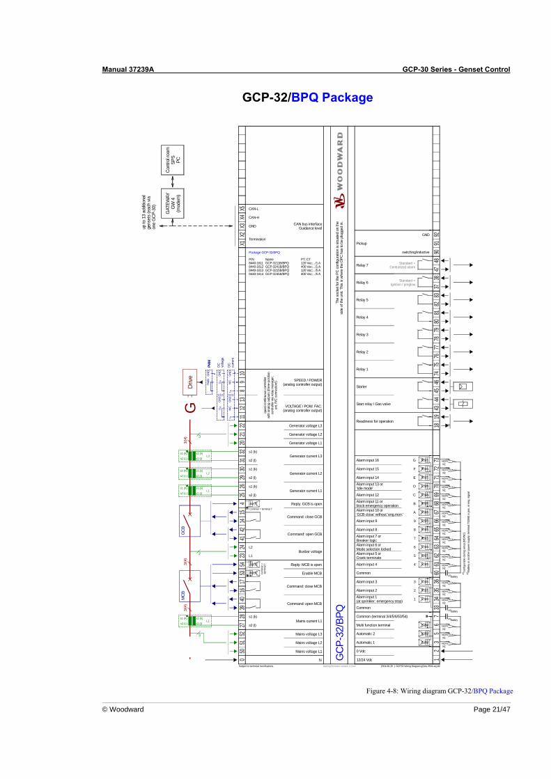
Figure 4-8: Wiring diagram GCP-32/BPQ Package
Manual 37239A GCP-30 Series - Genset Control
Page 22/47 © Woodward
GCP-32/XPD Package
17
Mains current L1
CAN-L
G
5
0 Vdc
2004-08-26 | GCP30 Wiring Diagram g2ww-3504-aq.skf
2
1
4
3
9
6
7
8
A
B
C
D
E
F
G
5051
5227
2853
5423
2441
1415
425
2642
2930
3132
2021
2211
1213
89
10X1
X2X3
X4X5
0 12
35
67
3334
3536
6061
6263
6465
6667
6869
7071
7273
1819
4344
4546
7475
7677
7879
8081
8283
9091
92
s2 (l)
s1 (k)
L1
L2
s2 (l)
s1 (k)
s2 (l)
s1 (k)
s2 (l)
s1 (k)
12/24 VdcN
Pickup
up to
13
addi
tiona
lge
nset
s (e
ach
via
one
GC
P-30
)
GAT
EWAY
GW
4(m
odem
)
Cont
rol r
oom
SPS
PC
Drive
Subject to technical mocifications.
Mains voltage L1
Mains voltage L3
Mains voltage L2
GC
B
Reply: GCB is open
Automatic 1
Readiness for operation
Automatic 2
Multi function terminal
Common (terminal 3/4/5/6/53/54)
Common
Alarm input 1(at sprinkler: emergency stop)
Alarm input 2
Alarm input 3
Common
Alarm input 4
Alarm input 5 orCrank terminate
Alarm input 6 orMode selection locked
Alarm input 7 orBreaker logic
Alarm input 8
Alarm input 9
Alarm input 10 or'GCB close' without 'eng.mon.'
Alarm input 11 orblock emergency operation
Alarm input 12
Alarm input 13 or'Idle mode'
Alarm input 14
Alarm input 15
Alarm input 16
Start relay / Gas valve
Starter
Relay 1
Relay 2
Relay 3
Relay 4
Relay 5
Command: open GCB
Generator current L1
Generator current L2
Generator current L3
Generator voltage L1
Generator voltage L2
Generator voltage L3
Command: close GCB
The
sock
et fo
r the
PC
con
figur
atio
n is
situ
ated
on
the
side
of th
e un
it. T
his
is w
here
the
DPC
has
to b
e pl
ugge
d in
.
CAN bus interfaceGuidance level
GND
switching/inductive
GND
CAN-H
Termination
Relay 6
3837
Relay 7
4847
Standard =Ignition / preglow
Standard =Centralized alarm
conf
igur
able
dur
ing
setu
p (N
O/N
C)#1
#1
Batte
ry o
r ano
ther
pow
er s
uppl
y; te
rmin
al 7
/33/
60 is
pos
. or n
eg. s
igna
l#2
NO/NC
4016
39
MC
B
Reply: MCB is open
Command: close MCB
Enable MCB
Command: open MCB
Busbar voltage
Battery#2
#2Battery
Battery#2
#1NO/NC
#1NO/NC
#1NO/NC
#1NO/NC
#1NO/NC
#1NO/NC
#1NO/NC
#1NO/NC
#1NO/NC
#1NO/NC
#1NO/NC
#1NO/NC
#1NO/NC
#1NO/NC
#1NO/NC
#1NO/NC
#1NO/NC
#1NO/NC
starting firmware version 4.2xxx
GCP
-32/
XPD
Package GCP-32/XPD
P/N8440-15688440-15698440-15708440-1571
NameGCP-3211B/XPDGCP-3241B/XPDGCP-3215B/XPDGCP-3245B/XPD
PT; CT120 Vac; ../1 A400 Vac; ../1 A120 Vac; ../5 A400 Vac; ../5 A
3/(4
) 3
s1 (K) s1 (k)
s2 (L) s2 (l)
s1 (K)
s2 (L) s2 (l)
s1 (K) s1 (k)
s2 (L) s2 (l)
s1 (k)
L2
L1
L3
3/(4
)3/
(4)
3
s1 (K) s1 (k)
s2 (L) s2 (l)L1
2
VOLTAGE / POW. FAC.(three-position controller)
raise
lower
raise
lower
SPEED / POWER(three-position controller)
105
106
107
108
109
110111
112113
120
121
122
123
9394
9596
9798
9910
010
110
210
310
4
GND
GND
AI
AI
Anal
og o
utpu
tm
anag
er
Analog output0/4-20 mA
Analog input 1 [T1]0/4-20 mA
Analog input 2 [T2]0/4-20 mA
Analog input 3 [T3]0/4-20 mA
Analog input 4 [T4]Pt100
Analog input 5 [T5]Pt100
Analog input 7 [T7]VDO Temperature 30-120 °C (0-380 Ohm)
or alternatively 86-248 °F (0-380 Ohm)
Analog input 6 [T6]VDO Pressure 0-5/10 bar (0-180 Ohm)
or alternatively 0-72.5/145 psi (0-180 Ohm)
Com
mon
=te
rmin
al 7
Common = terminal 7
124
127
128
#1NO/NC
#1NO/NC
#2Common
Operation mode STOP
Operation mode AUTOMATIC
Battery
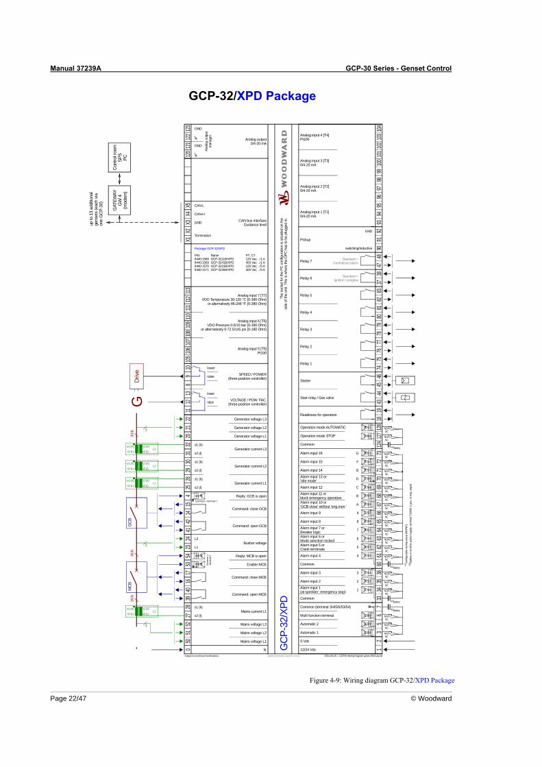
Figure 4-9: Wiring diagram GCP-32/XPD Package
Manual 37239A GCP-30 Series - Genset Control
© Woodward Page 23/47
GCP-32/XPQ Package
120
17
Mains current L1
CAN-L
G
5
0 Vdc
2004-08-26 | GCP30 Wiring Diagram g2ww-3504-aq.skf
2
1
4
3
9
6
7
8
A
B
C
D
E
F
G
5051
5227
2853
5423
2441
1415
425
2642
2930
3132
2021
2211
1213
89
10X1
X2X3
X4X5
0 12
35
67
3334
3536
6061
6263
6465
6667
6869
7071
7273
1819
4344
4546
7475
7677
7879
8081
8283
9091
92
s2 (l)
s1 (k)
L1
L2
s2 (l)
s1 (k)
s2 (l)
s1 (k)
s2 (l)
s1 (k)
12/24 VdcN
Pickup
up to
13
addi
tiona
lge
nset
s (e
ach
via
one
GC
P-30
)
GAT
EWAY
GW
4(m
odem
)
Cont
rol r
oom
SPS
PC
Drive
Subject to technical mocifications.
Mains voltage L1
Mains voltage L3
Mains voltage L2
GC
B
Reply: GCB is open
Automatic 1
Readiness for operation
Automatic 2
Multi function terminal
Common (terminal 3/4/5/6/53/54)
Common
Alarm input 1(at sprinkler: emergency stop)
Alarm input 2
Alarm input 3
Common
Alarm input 4
Alarm input 5 orCrank terminate
Alarm input 6 orMode selection locked
Alarm input 7 orBreaker logic
Alarm input 8
Alarm input 9
Alarm input 10 or'GCB close' without 'eng.mon.'
Alarm input 11 orblock emergency operation
Alarm input 12
Alarm input 13 or'Idle mode'
Alarm input 14
Alarm input 15
Alarm input 16
Start relay / Gas valve
Starter
Relay 1
Relay 2
Relay 3
Relay 4
Relay 5
Command: open GCB
Generator current L1
Generator current L2
Generator current L3
Generator voltage L1
Generator voltage L2
Generator voltage L3
Command: close GCB
The
sock
et fo
r the
PC
con
figur
atio
n is
situ
ated
on
the
side
of th
e un
it. T
his
is w
here
the
DPC
has
to b
e pl
ugge
d in
.
CAN bus interfaceGuidance level
GND
switching/inductive
GND
CAN-H
Termination
Relay 6
3837
Relay 7
4847
Standard =Ignition / preglow
Standard =Centralized alarm
conf
igur
able
dur
ing
setu
p (N
O/N
C)#1
#1
Batte
ry o
r ano
ther
pow
er s
uppl
y; te
rmin
al 7
/33/
60 is
pos
. or n
eg. s
igna
l#2
NO/NC
4016
39
MC
B
Reply: MCB is open
Command: close MCB
Enable MCB
Command: open MCB
Busbar voltage
Battery#2
#2Battery
Battery#2
#1NO/NC
#1NO/NC
#1NO/NC
#1NO/NC
#1NO/NC
#1NO/NC
#1NO/NC
#1NO/NC
#1NO/NC
#1NO/NC
#1NO/NC
#1NO/NC
#1NO/NC
#1NO/NC
#1NO/NC
#1NO/NC
#1NO/NC
#1NO/NC
starting firmware version 4.2xxx
GCP
-32/
XPQ
P/N8440-15728440-15738440-15748440-1575
PT; CT120 Vac; ../1 A400 Vac; ../1 A120 Vac; ../5 A400 Vac; ../5 A
Package GCP-32/XPQ
NameGCP-3211B/XPQGCP-3241B/XPQGCP-3215B/XPQGCP-3245B/XPQ
3/(4
) 3
s1 (K) s1 (k)
s2 (L) s2 (l)
s1 (K)
s2 (L) s2 (l)
s1 (K) s1 (k)
s2 (L) s2 (l)
s1 (k)
L2
L1
L3
3/(4
)3/
(4)
3
s1 (K) s1 (k)
s2 (L) s2 (l)L1
2
PWM
quas
i-con
tinuo
us c
ontro
ller
with
ana
log
outp
uts
(thre
e-po
sitio
nco
ntro
ller v
ia re
lay
man
ager
;ex
t. R/
C c
onne
ctio
n!)
DC
curre
nt
DC
volta
ge
PWM
SPEED / POWER(analog controller output)
VOLTAGE / POW. FAC.(analog controller output)
GND
GND
GND
PWM
UA
N/C
I A
GND
UA
GND
N/C
I A
105
106
107
108
109
110111
112113
121
122
123
9394
9596
9798
9910
010
110
210
310
4
GND
GND
AI
AI
Anal
og o
utpu
tm
anag
er
Analog output0/4-20 mA
Analog input 1 [T1]0/4-20 mA
Analog input 2 [T2]0/4-20 mA
Analog input 3 [T3]0/4-20 mA
Analog input 4 [T4]Pt100
Analog input 5 [T5]Pt100
Analog input 7 [T7]VDO Temperature 30-120 °C (0-380 Ohm)
or alternatively 86-248 °F (0-380 Ohm)
Analog input 6 [T6]VDO Pressure 0-5/10 bar (0-180 Ohm)
or alternatively 0-72.5/145 psi (0-180 Ohm)
Com
mon
=te
rmin
al 7
Common = terminal 7
124
127
128
#1NO/NC
#1NO/NC
#2Common
Operation mode STOP
Operation mode AUTOMATIC
Battery
Figure 4-10: Wiring diagram GCP-32/XPQ Package
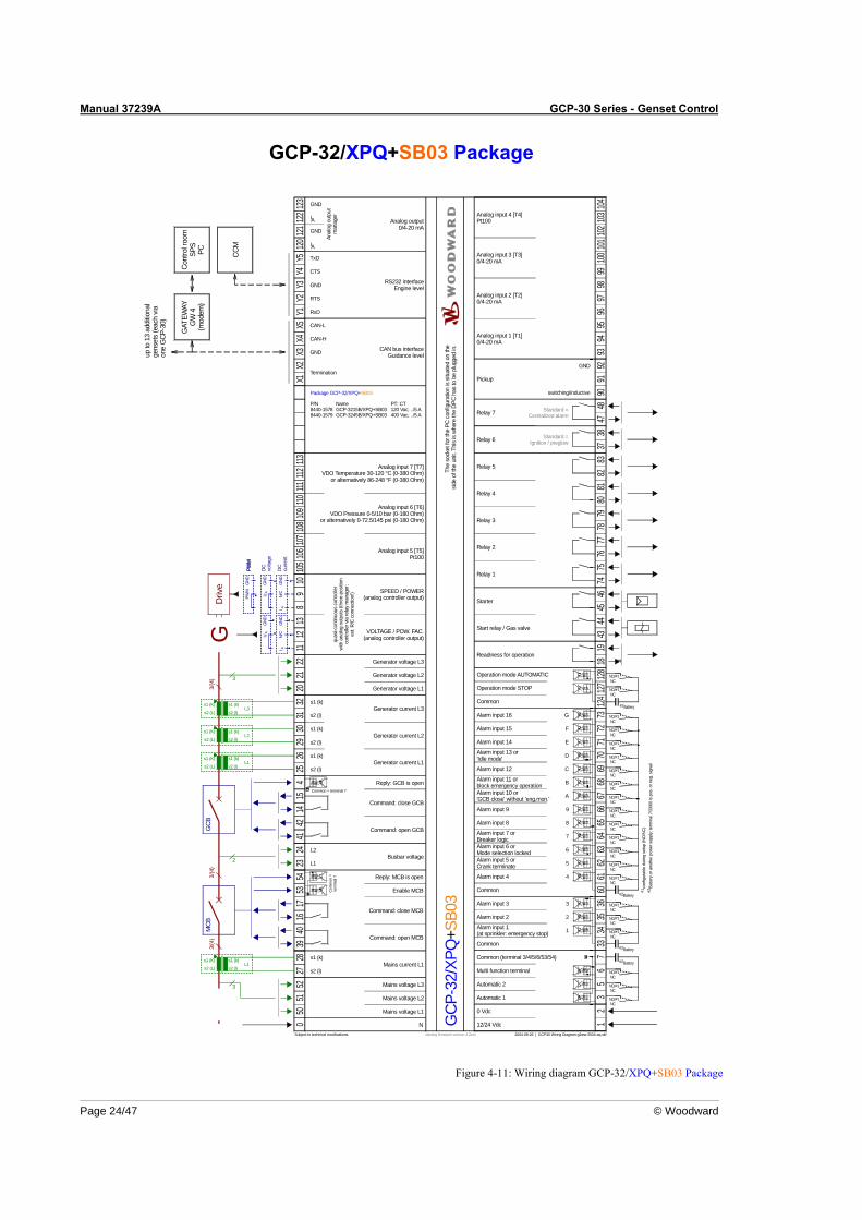
Manual 37239A GCP-30 Series - Genset Control
Page 24/47 © Woodward
GCP-32/XPQ+SB03 Package
17
Mains current L1
CAN-L
G
5
0 Vdc
2004-08-26 | GCP30 Wiring Diagram g2ww-3504-aq.skf
2
1
4
3
9
6
7
8
A
B
C
D
E
F
G
5051
5227
2853
5423
2441
1415
425
2642
2930
3132
2021
2211
1213
89
10X1
X2X3
X4X5
0 12
35
67
3334
3536
6061
6263
6465
6667
6869
7071
7273
1819
4344
4546
7475
7677
7879
8081
8283
9091
92
s2 (l)
s1 (k)
L1
L2
s2 (l)
s1 (k)
s2 (l)
s1 (k)
s2 (l)
s1 (k)
12/24 VdcN
Pickup
up to
13
addi
tiona
lge
nset
s (e
ach
viaon
e G
CP-3
0)
GAT
EWAY
GW
4(m
odem
)
Cont
rol r
oom
SPS
PC
Driv
e
Subject to technical mocifications.
Mains voltage L1
Mains voltage L3
Mains voltage L2
GCB
Reply: GCB is open
Automatic 1
Readiness for operation
Automatic 2
Multi function terminal
Common (terminal 3/4/5/6/53/54)
Common
Alarm input 1(at sprinkler: emergency stop)
Alarm input 2
Alarm input 3
Common
Alarm input 4
Alarm input 5 orCrank terminate
Alarm input 6 orMode selection locked
Alarm input 7 orBreaker logic
Alarm input 8
Alarm input 9
Alarm input 10 or'GCB close' without 'eng.mon.'
Alarm input 11 orblock emergency operation
Alarm input 12
Alarm input 13 or'Idle mode'
Alarm input 14
Alarm input 15
Alarm input 16
Start relay / Gas valve
Starter
Relay 1
Relay 2
Relay 3
Relay 4
Relay 5
Command: open GCB
Generator current L1
Generator current L2
Generator current L3
Generator voltage L1
Generator voltage L2
Generator voltage L3
Command: close GCB
The
sock
et fo
r the
PC
conf
igur
atio
n is
situ
ated
on
the
side
of th
e un
it. T
his
is wh
ere
the
DPC
has
to b
e pl
ugge
d in
.
CAN bus interfaceGuidance level
GND
switching/inductive
GND
CAN-H
Termination
Relay 6
3837
Relay 7
4847
Standard =Ignition / preglow
Standard =Centralized alarm
conf
igur
able
dur
ing
setu
p (N
O/N
C)
#1
#1
Batte
ry o
r ano
ther
pow
er s
uppl
y; te
rmin
al 7
/33/
60 is
pos
. or n
eg. s
igna
l#2
NO/NC
4016
39
MCB
Reply: MCB is open
Command: close MCB
Enable MCB
Command: open MCB
Busbar voltage
Battery#2
#2Battery
Battery#2
#1NO/NC
#1NO/NC
#1NO/NC
#1NO/NC
#1NO/NC
#1NO/NC
#1NO/NC
#1NO/NC
#1NO/NC
#1NO/NC
#1NO/NC
#1NO/NC
#1NO/NC
#1NO/NC
#1NO/NC
#1NO/NC
#1NO/NC
#1NO/NC
starting firmware version 4.2xxx
3/(4
) 3
s1 (K) s1 (k)
s2 (L) s2 (l)
s1 (K)
s2 (L) s2 (l)
s1 (K) s1 (k)
s2 (L) s2 (l)
s1 (k)
L2
L1
L3
3/(4
)3/
(4)
3
s1 (K) s1 (k)
s2 (L) s2 (l)L1
2
105
106
107
108
109
110111
112113
Y1Y2
Y3Y4
Y512
012
112
212
3
9394
9596
9798
9910
010
110
210
310
4
GND
GND
AI
AI
Anal
og o
utpu
tm
anag
er
RS232 interfaceEngine level
Analog output0/4-20 mA
GND
CTS
TxDCCM
PWM
Analog input 1 [T1]0/4-20 mA
Analog input 2 [T2]0/4-20 mA
Analog input 3 [T3]0/4-20 mA
Analog input 4 [T4]Pt100
Analog input 5 [T5]Pt100
Analog input 7 [T7]VDO Temperature 30-120 °C (0-380 Ohm)
or alternatively 86-248 °F (0-380 Ohm)
Analog input 6 [T6]VDO Pressure 0-5/10 bar (0-180 Ohm)
or alternatively 0-72.5/145 psi (0-180 Ohm)
quas
i-con
tinuo
us c
ontro
ller
with
ana
log
outp
uts
(thre
e-po
sitio
nco
ntro
ller v
ia re
lay
man
ager
;ex
t. R/
C co
nnec
tion!
)
DC
curre
nt
DC
volta
ge
PWM
SPEED / POWER(analog controller output)
VOLTAGE / POW. FAC.(analog controller output)
GN
D
GN
D
GN
DPW
M
UA
N/C
I A
GCP
-32/
XPQ
+SB0
3
Package GCP-32/XPQ+SB03
P/N8440-15788440-1579
NameGCP-3215B/XPQ+SB03GCP-3245B/XPQ+SB03
PT; CT120 Vac; ../5 A400 Vac; ../5 A
GN
DU
A
GN
DN/
CI A
RTS
RxD
Com
mon
=te
rmin
al 7
Common = terminal 7
124
127
128
#1NO/NC
#1NO/NC
#2Common
Operation mode STOP
Operation mode AUTOMATIC
Battery
Figure 4-11: Wiring diagram GCP-32/XPQ+SB03 Package
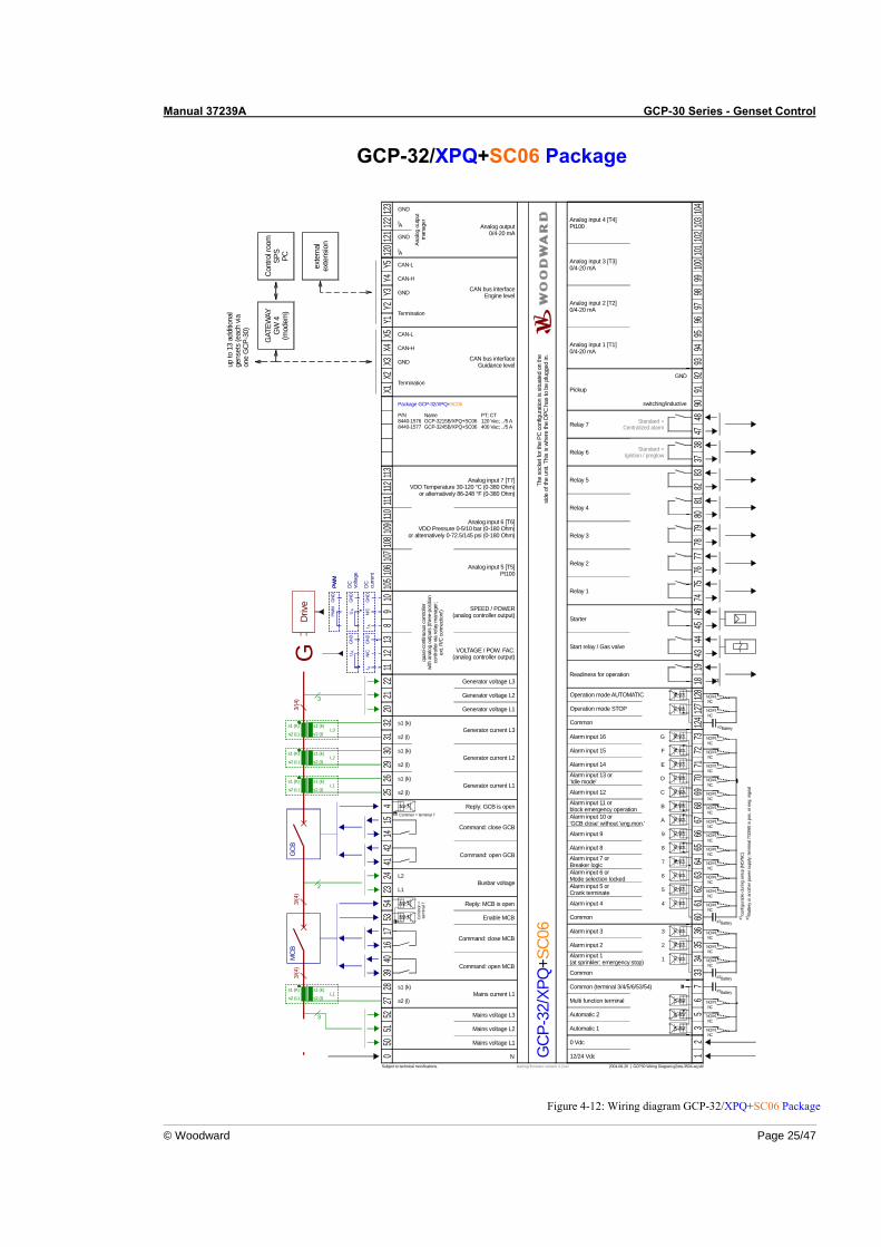
Manual 37239A GCP-30 Series - Genset Control
© Woodward Page 25/47
GCP-32/XPQ+SC06 Package
17
Mains current L1
CAN-L
G
5
0 Vdc
2004-08-26 | GCP30 Wiring Diagram g2ww-3504-aq.skf
2
1
4
3
9
6
7
8
A
B
C
D
E
F
G
5051
5227
2853
5423
2441
1415
425
2642
2930
3132
2021
2211
1213
89
1010
510
610
710
810
9110
111112
113X1
X2X3
X4X5
Y1Y2
Y3Y4
Y512
012
112
212
30 1
23
56
733
3435
3660
6162
6364
6566
6768
6970
7172
7318
1943
4445
4674
7576
7778
7980
8182
8390
9192
9394
9596
9798
9910
010
110
210
310
4
GND
s2 (l)
s1 (k)
L1
L2
s2 (l)
s1 (k)
s2 (l)
s1 (k)
s2 (l)
s1 (k)
GND
AI
AI
12/24 VdcN
Pickup
up to
13
addi
tiona
lge
nset
s (e
ach
via
one
GC
P-30
)
Anal
og o
utpu
tm
anag
er
GAT
EWAY
GW
4(m
odem
)
Cont
rol r
oom
SPS
PC
Drive
Subject to technical mocifications.
Mains voltage L1
Mains voltage L3
Mains voltage L2
GC
B
Reply: GCB is open
Automatic 1
Readiness for operation
Automatic 2
Multi function terminal
Common (terminal 3/4/5/6/53/54)
Common
Alarm input 1(at sprinkler: emergency stop)
Alarm input 2
Alarm input 3
Common
Alarm input 4
Alarm input 5 orCrank terminate
Alarm input 6 orMode selection locked
Alarm input 7 orBreaker logic
Alarm input 8
Alarm input 9
Alarm input 10 or'GCB close' without 'eng.mon.'
Alarm input 11 orblock emergency operation
Alarm input 12
Alarm input 13 or'Idle mode'
Alarm input 14
Alarm input 15
Alarm input 16
Start relay / Gas valve
Starter
Relay 1
Relay 2
Relay 3
Relay 4
Relay 5
Command: open GCB
Generator current L1
Generator current L2
Generator current L3
Generator voltage L1
Generator voltage L2
Generator voltage L3
CAN bus interfaceEngine level
Analog output0/4-20 mA
Command: close GCB
The
sock
et fo
r the
PC
con
figur
atio
n is
situ
ated
on
the
side
of th
e un
it. T
his
is w
here
the
DPC
has
to b
e pl
ugge
d in
.
CAN bus interfaceGuidance level
GND
switching/inductive
GND
CAN-H
Termination
GND
CAN-H
CAN-L
Termination
Relay 6
3837
Relay 7
4847
Standard =Ignition / preglow
Standard =Centralized alarm
exte
rnal
exte
nsio
nPW
M
conf
igur
able
dur
ing
setu
p (N
O/N
C)#1
#1
Batte
ry o
r ano
ther
pow
er s
uppl
y; te
rmin
al 7
/33/
60 is
pos
. or n
eg. s
igna
l#2
NO/NC
4016
39
MC
B
Reply: MCB is open
Command: close MCB
Enable MCB
Command: open MCB
Busbar voltage
Analog input 1 [T1]0/4-20 mA
Analog input 2 [T2]0/4-20 mA
Analog input 3 [T3]0/4-20 mA
Analog input 4 [T4]Pt100
Analog input 5 [T5]Pt100
Analog input 7 [T7]VDO Temperature 30-120 °C (0-380 Ohm)
or alternatively 86-248 °F (0-380 Ohm)
Analog input 6 [T6]VDO Pressure 0-5/10 bar (0-180 Ohm)
or alternatively 0-72.5/145 psi (0-180 Ohm)
quas
i-con
tinuo
us c
ontro
ller
with
ana
log
outp
uts
(thre
e-po
sitio
nco
ntro
ller v
ia re
lay
man
ager
;ex
t. R/
C c
onne
ctio
n!)
DC
curre
nt
DC
volta
ge
PWM
SPEED / POWER(analog controller output)
VOLTAGE / POW. FAC.(analog controller output)
Battery#2
#2Battery
Battery#2
#1NO/NC
#1NO/NC
#1NO/NC
#1NO/NC
#1NO/NC
#1NO/NC
#1NO/NC
#1NO/NC
#1NO/NC
#1NO/NC
#1NO/NC
#1NO/NC
#1NO/NC
#1NO/NC
#1NO/NC
#1NO/NC
#1NO/NC
#1NO/NC
starting firmware version 4.2xxx
GND
GND
GND
PWM
UA
N/C
I A
GCP
-32/
XPQ
+SC0
6
Package GCP-32/XPQ+SC06
P/N8440-15768440-1577
NameGCP-3215B/XPQ+SC06GCP-3245B/XPQ+SC06
PT; CT120 Vac; ../5 A400 Vac; ../5 A
GND
UA
GND
N/C
I A
3/(4
) 3
s1 (K) s1 (k)
s2 (L) s2 (l)
s1 (K)
s2 (L) s2 (l)
s1 (K) s1 (k)
s2 (L) s2 (l)
s1 (k)
L2
L1
L3
3/(4
)3/
(4)
3
s1 (K) s1 (k)
s2 (L) s2 (l)L1
2
Com
mon
=te
rmin
al 7
Common = terminal 7
124
127
128
#1NO/NC
#1NO/NC
#2Common
Operation mode STOP
Operation mode AUTOMATIC
Battery
Figure 4-12: Wiring diagram GCP-32/XPQ+SC06 Package
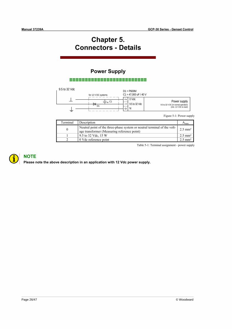
Manual 37239A GCP-30 Series - Genset Control
Page 26/47 © Woodward
Chapter 5. Connectors - Details
Power Supply ≡≡≡≡≡≡≡≡≡≡≡≡≡≡≡≡≡≡≡≡≡≡≡≡≡
01
2
N
0 Vdc
D1
C1
C1 = 47,000 uF / 40 VD1 = P600M
for 12 V DC systems
Power supply9.5 to 32 V DC (in normal operation)
(min. 12 V DC to start)9.5 to 32 Vdc
9.5 to 32 Vdc
Figure 5-1: Power supply
Terminal Description Amax
0 Neutral point of the three-phase system or neutral terminal of the volt-age transformer (Measuring reference point) 2.5 mm²
1 9.5 to 32 Vdc, 15 W 2.5 mm² 2 0 Vdc reference point 2.5 mm²
Table 5-1: Terminal assignment - power supply
NOTE Please note the above description in an application with 12 Vdc power supply.
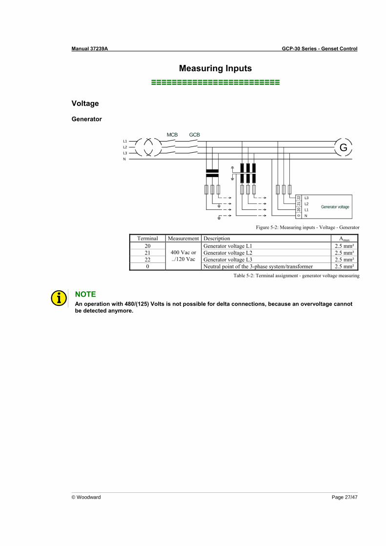
Manual 37239A GCP-30 Series - Genset Control
© Woodward Page 27/47
Measuring Inputs ≡≡≡≡≡≡≡≡≡≡≡≡≡≡≡≡≡≡≡≡≡≡≡≡≡
Voltage
Generator
L1L2L3N
Generator voltage
MCB GCB
0 N
2021
22 L3L2L1
G
Figure 5-2: Measuring inputs - Voltage - Generator
Terminal Measurement Description Amax 20 Generator voltage L1 2.5 mm² 21 Generator voltage L2 2.5 mm² 22 Generator voltage L3 2.5 mm² 0
400 Vac or ../120 Vac
Neutral point of the 3-phase system/transformer 2.5 mm² Table 5-2: Terminal assignment - generator voltage measuring
NOTE An operation with 480/(125) Volts is not possible for delta connections, because an overvoltage cannot be detected anymore.
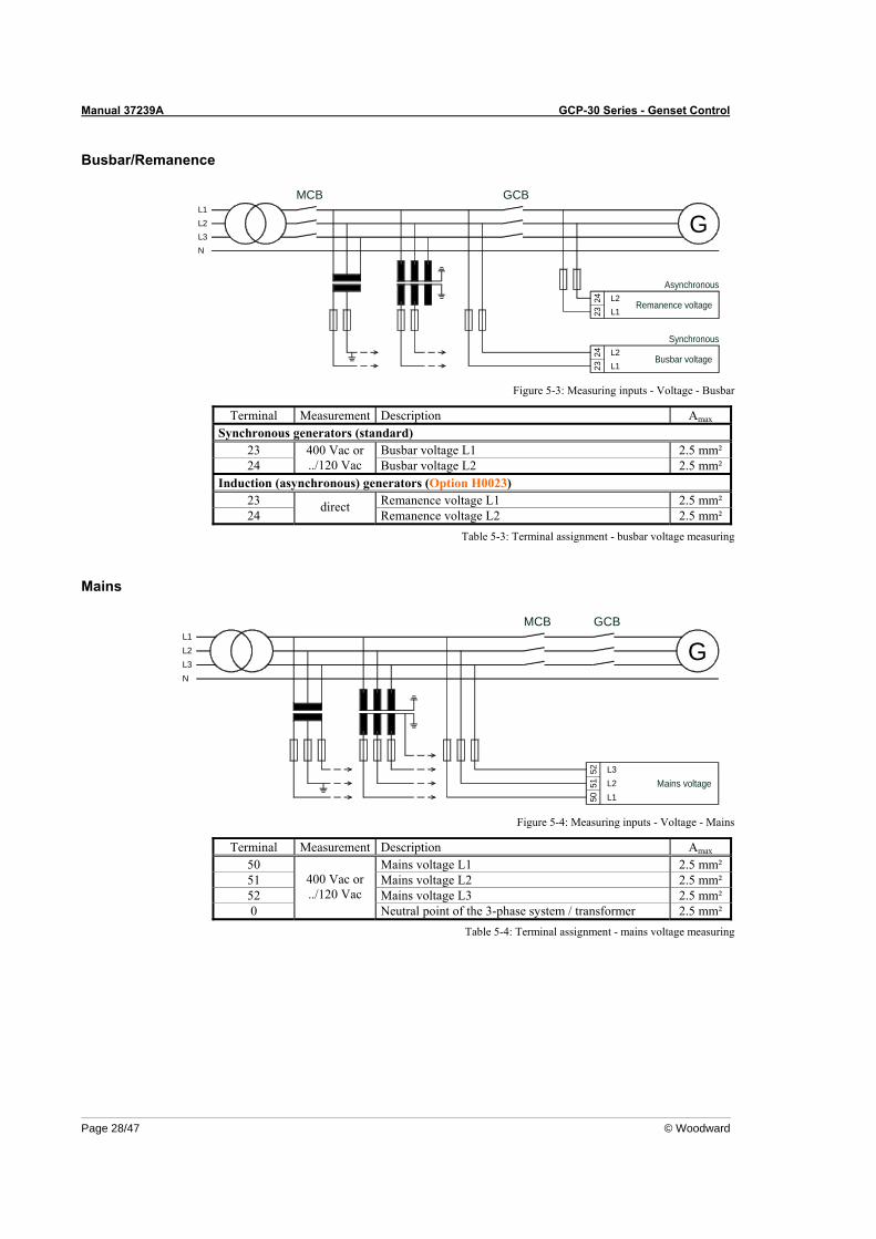
Manual 37239A GCP-30 Series - Genset Control
Page 28/47 © Woodward
Busbar/Remanence
N
L1L2L3
Remanence voltage
Busbar voltage
2324
2324
L1
L2L1
L2
MCB GCB
G
Asynchronous
Synchronous
Figure 5-3: Measuring inputs - Voltage - Busbar
Terminal Measurement Description Amax Synchronous generators (standard)
23 Busbar voltage L1 2.5 mm² 24
400 Vac or ../120 Vac Busbar voltage L2 2.5 mm²
Induction (asynchronous) generators (Option H0023) 23 Remanence voltage L1 2.5 mm² 24
direct Remanence voltage L2 2.5 mm²
Table 5-3: Terminal assignment - busbar voltage measuring
Mains
L3L2L1
N
Mains voltage
MCB
52 L3
5150
L2L1
GCB
G
Figure 5-4: Measuring inputs - Voltage - Mains
Terminal Measurement Description Amax 50 Mains voltage L1 2.5 mm² 51 Mains voltage L2 2.5 mm² 52 Mains voltage L3 2.5 mm² 0
400 Vac or ../120 Vac
Neutral point of the 3-phase system / transformer 2.5 mm² Table 5-4: Terminal assignment - mains voltage measuring
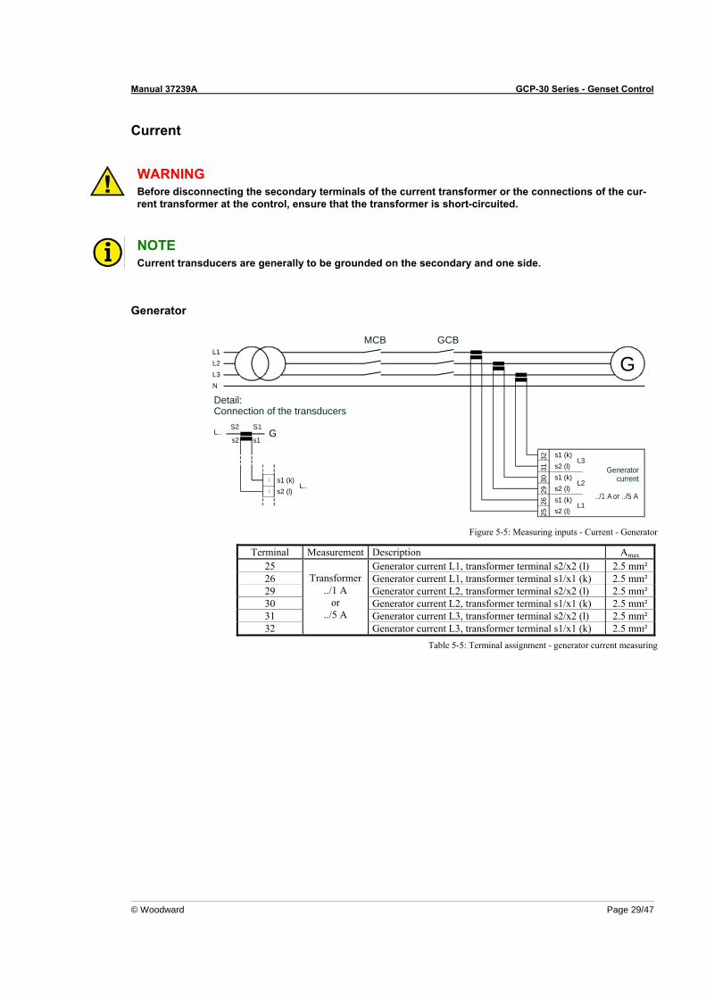
Manual 37239A GCP-30 Series - Genset Control
© Woodward Page 29/47
Current
WARNING Before disconnecting the secondary terminals of the current transformer or the connections of the cur-rent transformer at the control, ensure that the transformer is short-circuited.
NOTE Current transducers are generally to be grounded on the secondary and one side.
Generator
N
L2L3
L1
Detail:Connection of the transducers
S2
s2L..
Generatorcurrent
../1 A or ../5 A
s1 (k)..
L..s2 (l)..
MCB
GS1
s1
L332 s1 (k)
31 s2 (l)
3029
2625
s1 (k)s2 (l)
s2 (l)s1 (k)
L2
L1
GCB
G
Figure 5-5: Measuring inputs - Current - Generator
Terminal Measurement Description Amax 25 Generator current L1, transformer terminal s2/x2 (l) 2.5 mm² 26 Generator current L1, transformer terminal s1/x1 (k) 2.5 mm² 29 Generator current L2, transformer terminal s2/x2 (l) 2.5 mm² 30 Generator current L2, transformer terminal s1/x1 (k) 2.5 mm² 31 Generator current L3, transformer terminal s2/x2 (l) 2.5 mm² 32
Transformer ../1 A
or ../5 A
Generator current L3, transformer terminal s1/x1 (k) 2.5 mm² Table 5-5: Terminal assignment - generator current measuring
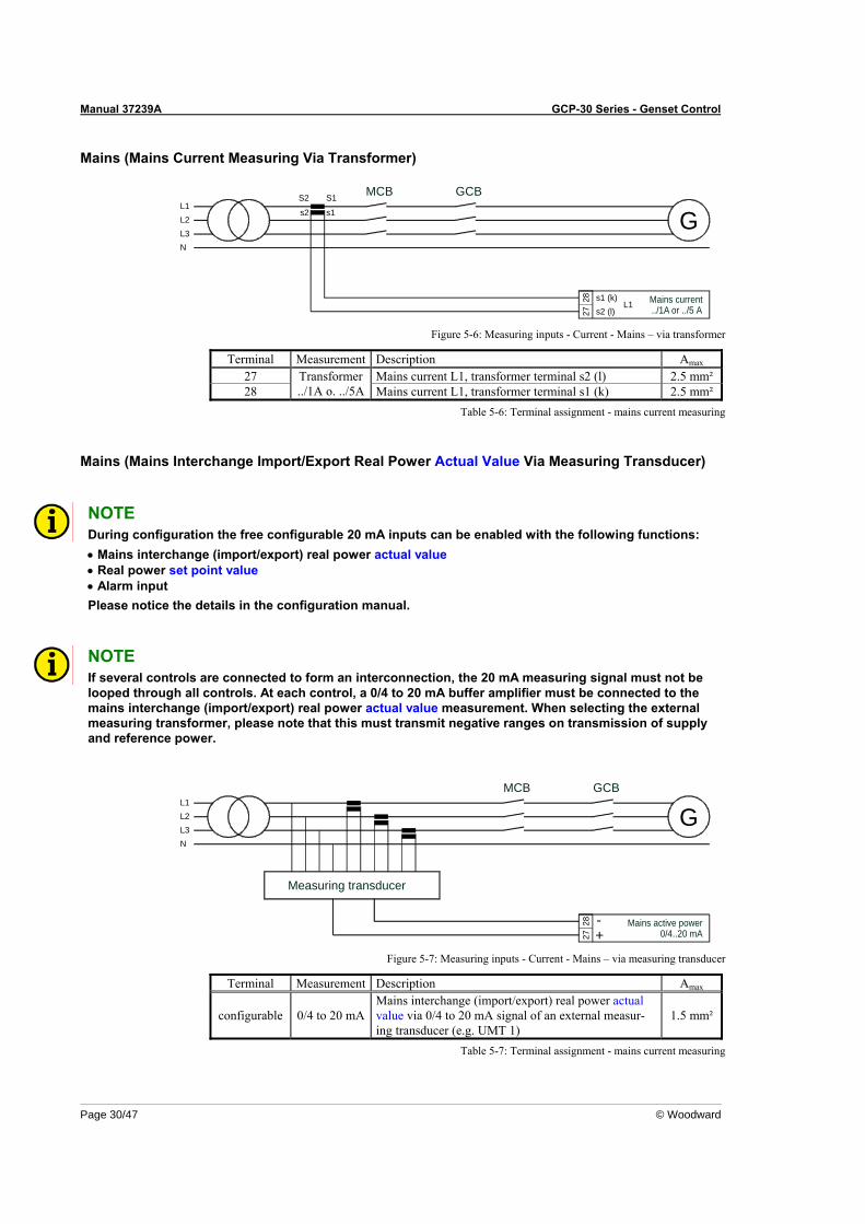
Manual 37239A GCP-30 Series - Genset Control
Page 30/47 © Woodward
Mains (Mains Current Measuring Via Transformer)
L2L3
L1
N
GCBS1
s1
S2
s2
MCB
G
Mains current../1A or ../5 A
s1 (k)
2728
s2 (l)L1
Figure 5-6: Measuring inputs - Current - Mains – via transformer
Terminal Measurement Description Amax 27 Mains current L1, transformer terminal s2 (l) 2.5 mm² 28
Transformer ../1A o. ../5A Mains current L1, transformer terminal s1 (k) 2.5 mm²
Table 5-6: Terminal assignment - mains current measuring
Mains (Mains Interchange Import/Export Real Power Actual Value Via Measuring Transducer)
NOTE During configuration the free configurable 20 mA inputs can be enabled with the following functions: • Mains interchange (import/export) real power actual value • Real power set point value • Alarm input Please notice the details in the configuration manual.
NOTE If several controls are connected to form an interconnection, the 20 mA measuring signal must not be looped through all controls. At each control, a 0/4 to 20 mA buffer amplifier must be connected to the mains interchange (import/export) real power actual value measurement. When selecting the external measuring transformer, please note that this must transmit negative ranges on transmission of supply and reference power.
Measuring transducer
MCB GCB
Mains active power0/4..20 mA27
28
GL2L3
L1
N
+-
Figure 5-7: Measuring inputs - Current - Mains – via measuring transducer
Terminal Measurement Description Amax
configurable 0/4 to 20 mAMains interchange (import/export) real power actual value via 0/4 to 20 mA signal of an external measur-ing transducer (e.g. UMT 1)
1.5 mm²
Table 5-7: Terminal assignment - mains current measuring
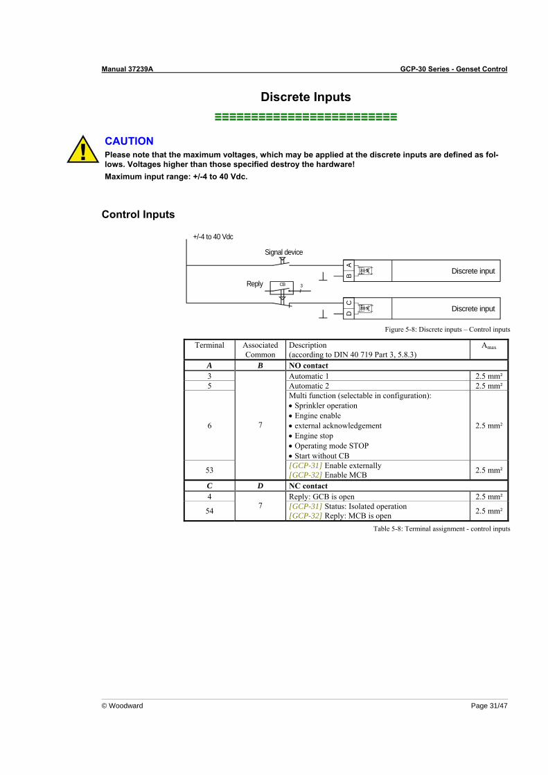
Manual 37239A GCP-30 Series - Genset Control
© Woodward Page 31/47
Discrete Inputs ≡≡≡≡≡≡≡≡≡≡≡≡≡≡≡≡≡≡≡≡≡≡≡≡≡
CAUTION Please note that the maximum voltages, which may be applied at the discrete inputs are defined as fol-lows. Voltages higher than those specified destroy the hardware! Maximum input range: +/-4 to 40 Vdc.
Control Inputs
Signal device
+/-4 to 40 Vdc
Reply
D
CB 3
BA
C
Discrete input
Discrete input
Figure 5-8: Discrete inputs – Control inputs
Terminal Associated Common
Description (according to DIN 40 719 Part 3, 5.8.3)
Amax
A B NO contact 3 Automatic 1 2.5 mm² 5 Automatic 2 2.5 mm²
6
Multi function (selectable in configuration): • Sprinkler operation • Engine enable • external acknowledgement • Engine stop • Operating mode STOP • Start without CB
2.5 mm²
53
7
[GCP-31] Enable externally [GCP-32] Enable MCB 2.5 mm²
C D NC contact 4 Reply: GCB is open 2.5 mm²
54 7 [GCP-31] Status: Isolated operation
[GCP-32] Reply: MCB is open 2.5 mm²
Table 5-8: Terminal assignment - control inputs
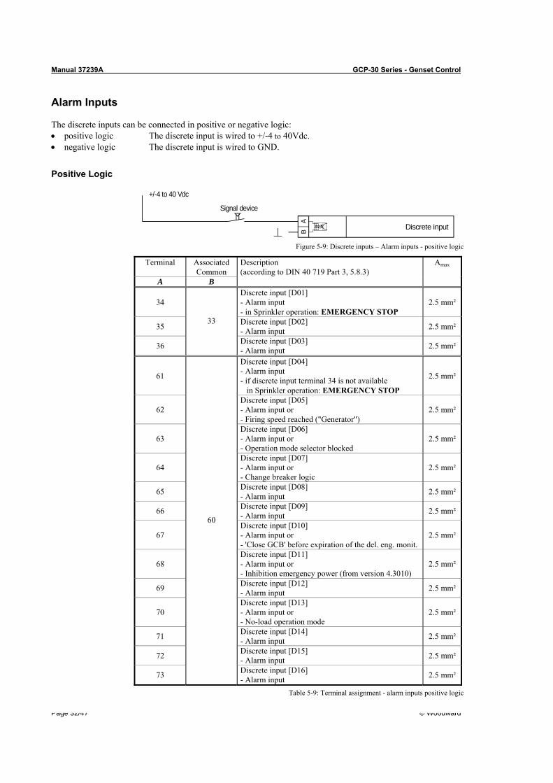
Manual 37239A GCP-30 Series - Genset Control
Page 32/47 © Woodward
Alarm Inputs
The discrete inputs can be connected in positive or negative logic: • positive logic The discrete input is wired to +/-4 to 40Vdc. • negative logic The discrete input is wired to GND.
Positive Logic
Signal device
Discrete input
AB
+/-4 to 40 Vdc
Figure 5-9: Discrete inputs – Alarm inputs - positive logic
Terminal AssociatedCommon
Amax
A B
Description (according to DIN 40 719 Part 3, 5.8.3)
34 Discrete input [D01] - Alarm input - in Sprinkler operation: EMERGENCY STOP
2.5 mm²
35 Discrete input [D02] - Alarm input 2.5 mm²
36
33
Discrete input [D03] - Alarm input 2.5 mm²
61
Discrete input [D04] - Alarm input - if discrete input terminal 34 is not available in Sprinkler operation: EMERGENCY STOP
2.5 mm²
62 Discrete input [D05] - Alarm input or - Firing speed reached ("Generator")
2.5 mm²
63 Discrete input [D06] - Alarm input or - Operation mode selector blocked
2.5 mm²
64 Discrete input [D07] - Alarm input or - Change breaker logic
2.5 mm²
65 Discrete input [D08] - Alarm input 2.5 mm²
66 Discrete input [D09] - Alarm input 2.5 mm²
67 Discrete input [D10] - Alarm input or - 'Close GCB' before expiration of the del. eng. monit.
2.5 mm²
68 Discrete input [D11] - Alarm input or - Inhibition emergency power (from version 4.3010)
2.5 mm²
69 Discrete input [D12] - Alarm input 2.5 mm²
70 Discrete input [D13] - Alarm input or - No-load operation mode
2.5 mm²
71 Discrete input [D14] - Alarm input 2.5 mm²
72 Discrete input [D15] - Alarm input 2.5 mm²
73
60
Discrete input [D16] - Alarm input 2.5 mm²
Table 5-9: Terminal assignment - alarm inputs positive logic
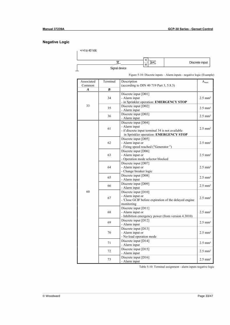
Manual 37239A GCP-30 Series - Genset Control
© Woodward Page 33/47
Negative Logic
Discrete input
AB
Signal device
+/-4 to 40 Vdc
Figure 5-10: Discrete inputs – Alarm inputs - negative logic (Example)
AssociatedCommon
Terminal Amax
A B
Description (according to DIN 40 719 Part 3, 5.8.3)
34 Discrete input [D01] - Alarm input - in Sprinkler operation: EMERGENCY STOP
2.5 mm²
35 Discrete input [D02] - Alarm input 2.5 mm²
33
36 Discrete input [D03] - Alarm input 2.5 mm²
61
Discrete input [D04] - Alarm input - if discrete input terminal 34 is not available in Sprinkler operation: EMERGENCY STOP
2.5 mm²
62 Discrete input [D05] - Alarm input or - Firing speed reached ("Generator ")
2.5 mm²
63 Discrete input [D06] - Alarm input or - Operation mode selector blocked
2.5 mm²
64 Discrete input [D07] - Alarm input or - Change breaker logic
2.5 mm²
65 Discrete input [D08] - Alarm input 2.5 mm²
66 Discrete input [D09] - Alarm input 2.5 mm²
67
Discrete input [D10] - Alarm input or - 'Close GCB' before expiration of the delayed engine monitoring
2.5 mm²
68 Discrete input [D11] - Alarm input or - Inhibition emergency power (from version 4.3010)
2.5 mm²
69 Discrete input [D12] - Alarm input 2.5 mm²
70 Discrete input [D13] - Alarm input or - No-load operation mode
2.5 mm²
71 Discrete input [D14] - Alarm input 2.5 mm²
72 Discrete input [D15] - Alarm input 2.5 mm²
60
73 Discrete input [D16] - Alarm input 2.5 mm²
Table 5-10: Terminal assignment - alarm inputs negative logic
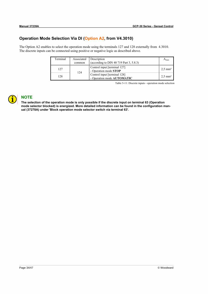
Manual 37239A GCP-30 Series - Genset Control
Page 34/47 © Woodward
Operation Mode Selection Via DI (Option A2, from V4.3010)
The Option A2 enables to select the operation mode using the terminals 127 and 128 externally from 4.3010. The discrete inputs can be connected using positive or negative logic as described above.
Terminal Associatedcommon
Description (according to DIN 40 719 Part 3, 5.8.3)
Amax
127 Control input [terminal 127] - Operation mode STOP 2,5 mm²
128 124
Control input [terminal 128] - Operation mode AUTOMATIC 2,5 mm²
Table 5-11: Discrete inputs - operation mode selection
NOTE The selection of the operation mode is only possible if the discrete input on terminal 63 (Operation mode selector blocked) is energized. More detailed information can be found in the configuration man-ual (37278A) under 'Block operation mode selector switch via terminal 63'.
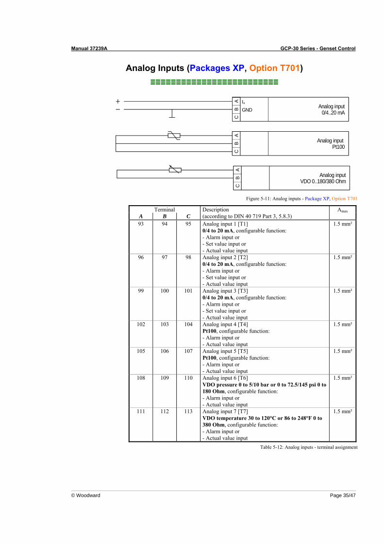
Manual 37239A GCP-30 Series - Genset Control
© Woodward Page 35/47
Analog Inputs (Packages XP, Option T701) ≡≡≡≡≡≡≡≡≡≡≡≡≡≡≡≡≡≡≡≡≡≡≡≡≡
GND
CC
AB
CA aI
BA
B
Analog inputVDO 0..180/380 Ohm
Analog input0/4..20 mA
Analog input Pt100
Figure 5-11: Analog inputs - Package XP, Option T701
Terminal Amax A B C
Description (according to DIN 40 719 Part 3, 5.8.3)
93 94 95 Analog input 1 [T1] 0/4 to 20 mA, configurable function: - Alarm input or - Set value input or - Actual value input
1.5 mm²
96 97 98 Analog input 2 [T2] 0/4 to 20 mA, configurable function: - Alarm input or - Set value input or - Actual value input
1.5 mm²
99 100 101 Analog input 3 [T3] 0/4 to 20 mA, configurable function: - Alarm input or - Set value input or - Actual value input
1.5 mm²
102 103 104 Analog input 4 [T4] Pt100, configurable function: - Alarm input or - Actual value input
1.5 mm²
105 106 107 Analog input 5 [T5] Pt100, configurable function: - Alarm input or - Actual value input
1.5 mm²
108 109 110 Analog input 6 [T6] VDO pressure 0 to 5/10 bar or 0 to 72.5/145 psi 0 to 180 Ohm, configurable function: - Alarm input or - Actual value input
1.5 mm²
111 112 113 Analog input 7 [T7] VDO temperature 30 to 120°C or 86 to 248°F 0 to 380 Ohm, configurable function: - Alarm input or - Actual value input
1.5 mm²
Table 5-12: Analog inputs - terminal assignment
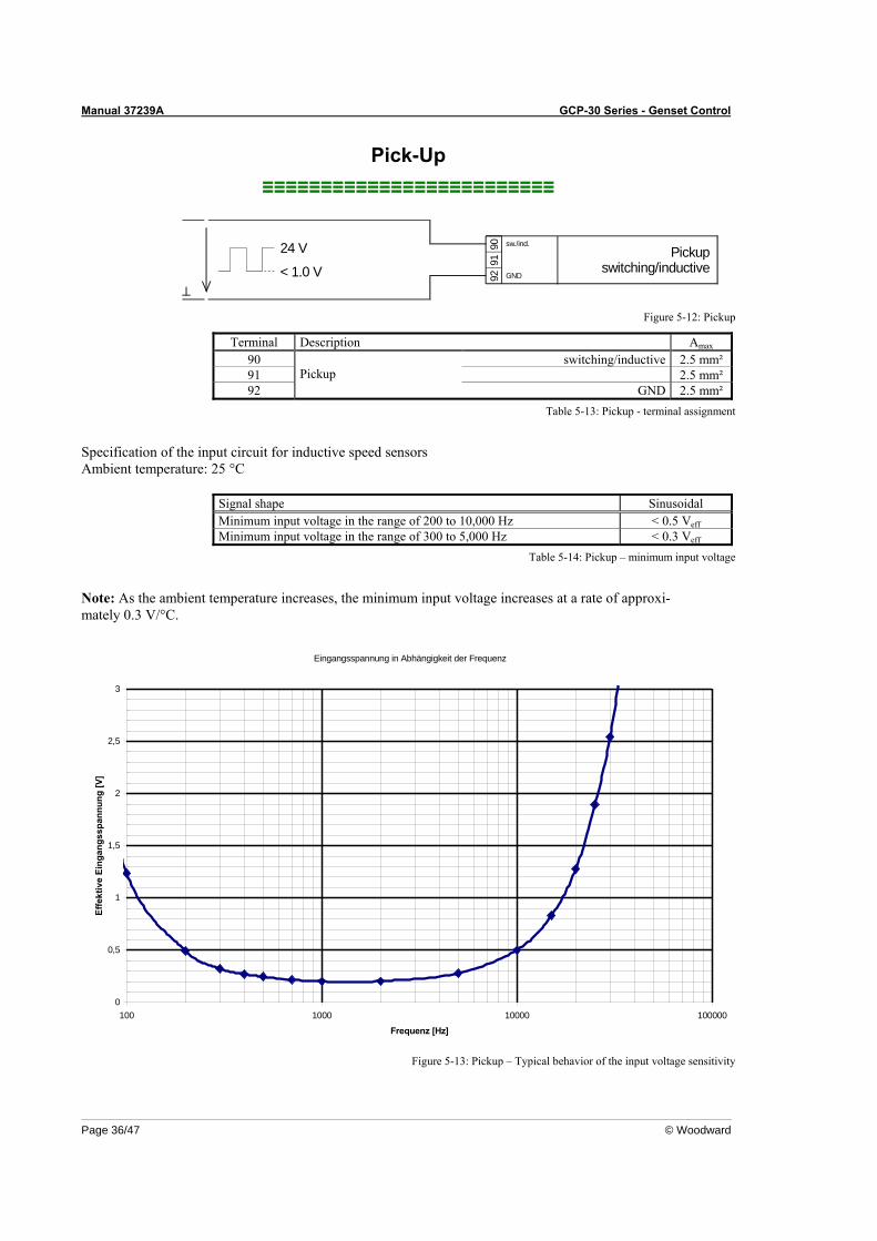
Manual 37239A GCP-30 Series - Genset Control
Page 36/47 © Woodward
Pick-Up ≡≡≡≡≡≡≡≡≡≡≡≡≡≡≡≡≡≡≡≡≡≡≡≡≡
24 V Pickupswitching/inductive< 1.0 V
9091
GND92
sw./ind.
Figure 5-12: Pickup
Terminal Description Amax 90 switching/inductive 2.5 mm² 91 2.5 mm² 92
Pickup GND 2.5 mm²
Table 5-13: Pickup - terminal assignment
Specification of the input circuit for inductive speed sensors Ambient temperature: 25 °C
Signal shape Sinusoidal Minimum input voltage in the range of 200 to 10,000 Hz < 0.5 Veff Minimum input voltage in the range of 300 to 5,000 Hz < 0.3 Veff
Table 5-14: Pickup – minimum input voltage
Note: As the ambient temperature increases, the minimum input voltage increases at a rate of approxi-mately 0.3 V/°C.
Eingangsspannung in Abhängigkeit der Frequenz
0
0,5
1
1,5
2
2,5
3
100 1000 10000 100000
Frequenz [Hz]
Effe
ktiv
e Ei
ngan
gssp
annu
ng [V
]
Figure 5-13: Pickup – Typical behavior of the input voltage sensitivity
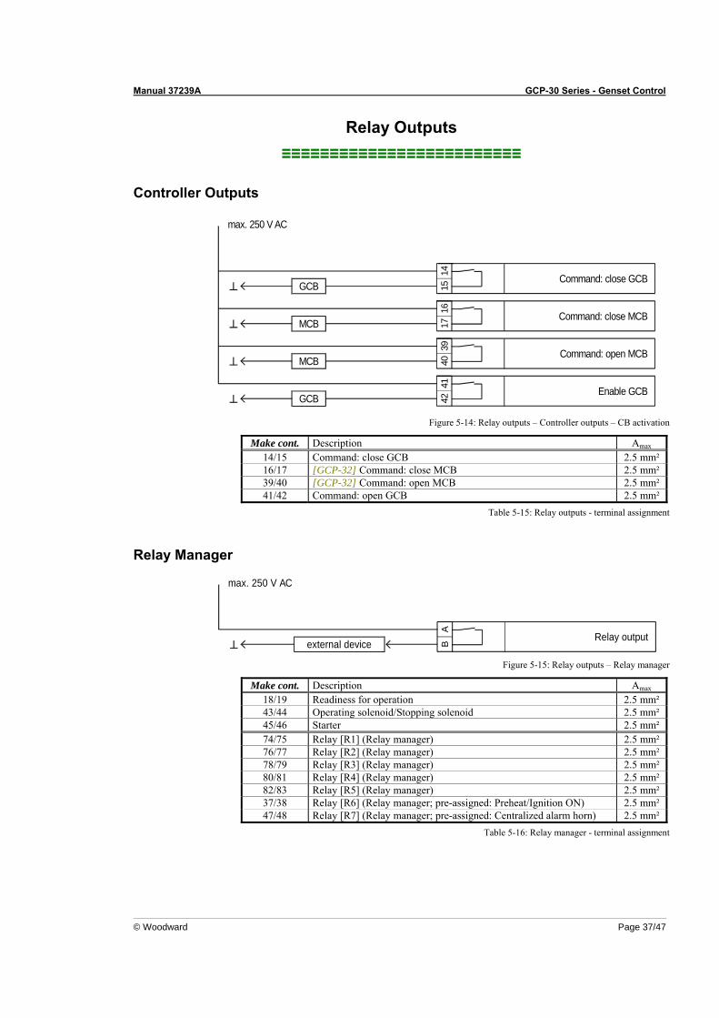
Manual 37239A GCP-30 Series - Genset Control
© Woodward Page 37/47
Relay Outputs ≡≡≡≡≡≡≡≡≡≡≡≡≡≡≡≡≡≡≡≡≡≡≡≡≡
Controller Outputs
Enable GCB
max. 250 V AC
Command: close GCB
Command: close MCB
Command: open MCB
GCB
MCB
MCB
GCB
4142
1417
4039
1615
Figure 5-14: Relay outputs – Controller outputs – CB activation
Make cont. Description Amax 14/15 Command: close GCB 2.5 mm² 16/17 [GCP-32] Command: close MCB 2.5 mm² 39/40 [GCP-32] Command: open MCB 2.5 mm² 41/42 Command: open GCB 2.5 mm²
Table 5-15: Relay outputs - terminal assignment
Relay Manager
AB
Relay outputexternal device
max. 250 V AC
Figure 5-15: Relay outputs – Relay manager
Make cont. Description Amax 18/19 Readiness for operation 2.5 mm² 43/44 Operating solenoid/Stopping solenoid 2.5 mm² 45/46 Starter 2.5 mm² 74/75 Relay [R1] (Relay manager) 2.5 mm² 76/77 Relay [R2] (Relay manager) 2.5 mm² 78/79 Relay [R3] (Relay manager) 2.5 mm² 80/81 Relay [R4] (Relay manager) 2.5 mm² 82/83 Relay [R5] (Relay manager) 2.5 mm² 37/38 Relay [R6] (Relay manager; pre-assigned: Preheat/Ignition ON) 2.5 mm² 47/48 Relay [R7] (Relay manager; pre-assigned: Centralized alarm horn) 2.5 mm²
Table 5-16: Relay manager - terminal assignment
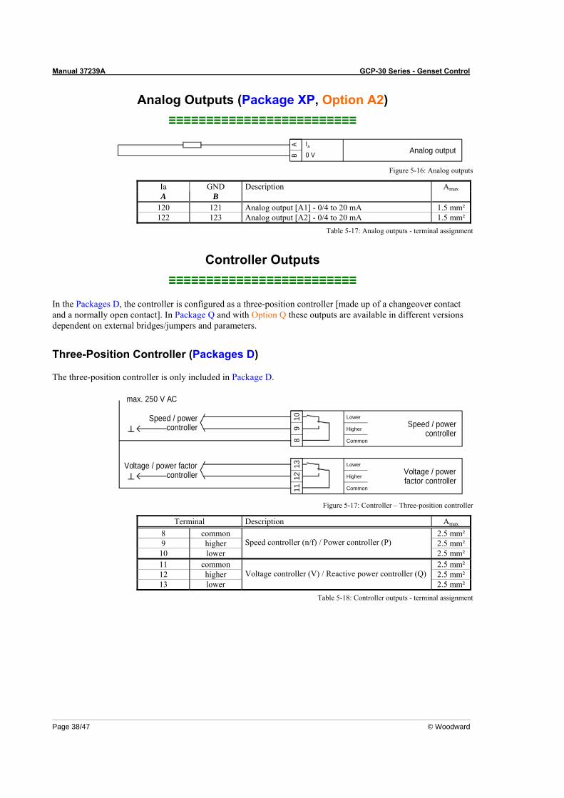
Manual 37239A GCP-30 Series - Genset Control
Page 38/47 © Woodward
Analog Outputs (Package XP, Option A2) ≡≡≡≡≡≡≡≡≡≡≡≡≡≡≡≡≡≡≡≡≡≡≡≡≡
Analog output0 VA
BA I
Figure 5-16: Analog outputs
Ia GND Description Amax A B
120 121 Analog output [A1] - 0/4 to 20 mA 1.5 mm² 122 123 Analog output [A2] - 0/4 to 20 mA 1.5 mm²
Table 5-17: Analog outputs - terminal assignment
Controller Outputs ≡≡≡≡≡≡≡≡≡≡≡≡≡≡≡≡≡≡≡≡≡≡≡≡≡
In the Packages D, the controller is configured as a three-position controller [made up of a changeover contact and a normally open contact]. In Package Q and with Option Q these outputs are available in different versions dependent on external bridges/jumpers and parameters.
Three-Position Controller (Packages D)
The three-position controller is only included in Package D.
1112
13Voltage / power factorcontroller
Common
Higher
LowerVoltage / powerfactor controller
8 Common
Speed / powercontroller Speed / power
controller
max. 250 V AC
910 Lower
Higher
Figure 5-17: Controller – Three-position controller
Terminal Description Amax 8 common 2.5 mm² 9 higher 2.5 mm²
10 lower Speed controller (n/f) / Power controller (P)
2.5 mm² 11 common 2.5 mm² 12 higher 2.5 mm² 13 lower
Voltage controller (V) / Reactive power controller (Q) 2.5 mm²
Table 5-18: Controller outputs - terminal assignment
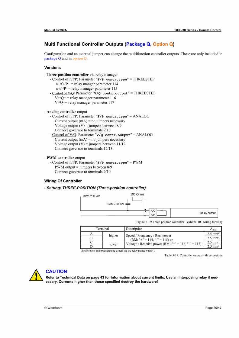
Manual 37239A GCP-30 Series - Genset Control
© Woodward Page 39/47
Multi Functional Controller Outputs (Package Q, Option Q)
Configuration and an external jumper can change the multifunction controller outputs. These are only included in package Q and in option Q.
Versions
- Three-position controller via relay manager - Control of n/f/P: Parameter "F/P contr.type" = THREESTEP n+/f+/P+ = relay manger parameter 114 n-/f-/P- = relay manager parameter 115 - Control of V/Q: Parameter "V/Q contr.output" = THREESTEP V+/Q+ = relay manager parameter 116 V-/Q- = relay manager parameter 117
- Analog controller output
- Control of n/f/P: Parameter "F/P contr.type" = ANALOG Current output (mA) = no jumpers necessary Voltage output (V) = jumpers between 8/9 Connect governor to terminals 9/10 - Control of V/Q: Parameter "V/Q contr.output" = ANALOG Current output (mA) = no jumpers necessary Voltage output (V) = jumpers between 11/12 Connect governor to terminals 12/13
- PWM controller output
- Control of n/f/P: Parameter "F/P contr.type" = PWM PWM output = jumpers between 8/9 Connect governor to terminals 9/10
Wiring Of Controller
- Setting: THREE-POSITION (Three-position controller)
A/CB/D
Relay output
max. 250 Vac 100 Ohms
3,3nF/1000V
Figure 5-18: Three-position controller – external RC wiring for relay
Terminal Description Amax A 2.5 mm² B
higher 2.5 mm²
C 2.5 mm² D lower
Speed / Frequency / Real power (RM: "+" = 114, "-" = 115) or Voltage / Reactive power (RM: "+" = 116, "-" = 117)
2.5 mm² The selection and programming occurs via the relay manager (RM).
Table 5-19: Controller outputs - three-position
CAUTION Refer to Technical Data on page 43 for information about current limits. Use an interposing relay if nec-essary. Currents higher than those specified destroy the hardware!
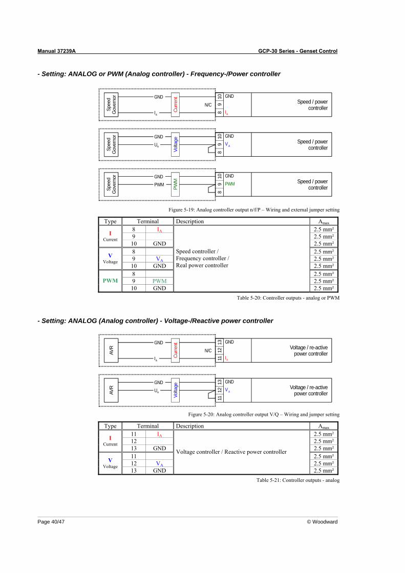
Manual 37239A GCP-30 Series - Genset Control
Page 40/47 © Woodward
- Setting: ANALOG or PWM (Analog controller) - Frequency-/Power controller
GND
Speed / powercontroller
810
9
GNDPW
M
Spee
dG
over
nor GND
PWM PWM
Speed / powercontroller
810
9 A
Volta
ge
Spee
dG
over
nor
AUGND
Speed / powercontroller
8 AI
109
GND
Cur
rent
Spee
dG
over
nor
AI
GNDN/C
V
Figure 5-19: Analog controller output n/f/P – Wiring and external jumper setting
Type Terminal Description Amax 8 IA 2.5 mm² 9 2.5 mm² I
Current 10 GND 2.5 mm² 8 2.5 mm² 9 VA 2.5 mm² V
Voltage 10 GND 2.5 mm² 8 2.5 mm² 9 PWM 2.5 mm² PWM 10 GND
Speed controller / Frequency controller / Real power controller
2.5 mm² Table 5-20: Controller outputs - analog or PWM
- Setting: ANALOG (Analog controller) - Voltage-/Reactive power controller
Voltage / re-activepower controller
11 AI
1312
GND
Cur
rent
AVR
AIN/C
GND
Voltage / re-activepower controller
1113
12 A
Volta
ge
AUGND GND
AVR V
Figure 5-20: Analog controller output V/Q – Wiring and jumper setting
Type Terminal Description Amax 11 IA 2.5 mm² 12 2.5 mm² I
Current 13 GND 2.5 mm² 11 2.5 mm² 12 VA 2.5 mm² V
Voltage 13 GND
Voltage controller / Reactive power controller
2.5 mm² Table 5-21: Controller outputs - analog
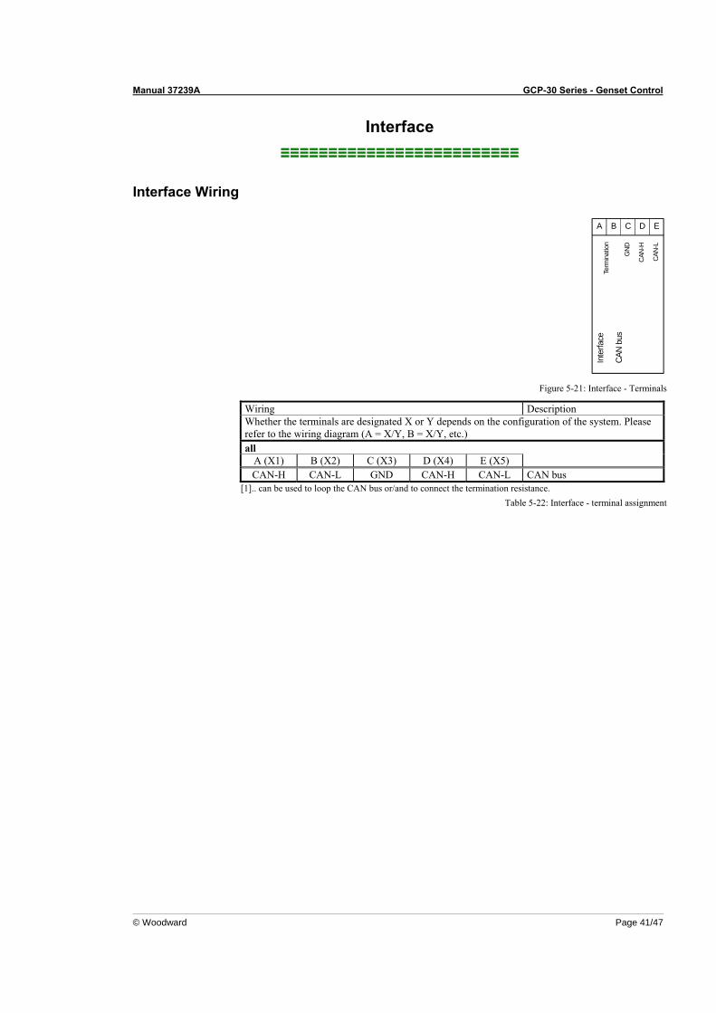
Manual 37239A GCP-30 Series - Genset Control
© Woodward Page 41/47
Interface ≡≡≡≡≡≡≡≡≡≡≡≡≡≡≡≡≡≡≡≡≡≡≡≡≡
Interface Wiring
Inte
rface
CAN
bus
CAN
-L
Term
inat
ion
CAN
-H
GND
CA B D E
Figure 5-21: Interface - Terminals
Wiring Description Whether the terminals are designated X or Y depends on the configuration of the system. Please refer to the wiring diagram (A = X/Y, B = X/Y, etc.) all
A (X1) B (X2) C (X3) D (X4) E (X5) CAN-H CAN-L GND CAN-H CAN-L CAN bus
[1].. can be used to loop the CAN bus or/and to connect the termination resistance. Table 5-22: Interface - terminal assignment
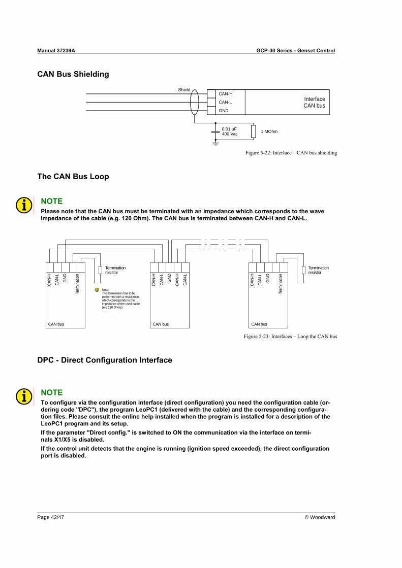
Manual 37239A GCP-30 Series - Genset Control
Page 42/47 © Woodward
CAN Bus Shielding
InterfaceCAN bus
CAN-H
CAN-L
GND
Shield
1 MOhm0.01 uF400 Vac
Figure 5-22: Interface – CAN bus shielding
The CAN Bus Loop
NOTE Please note that the CAN bus must be terminated with an impedance which corresponds to the wave impedance of the cable (e.g. 120 Ohm). The CAN bus is terminated between CAN-H and CAN-L.
GND
CAN-
L
CAN-
H
GND
GND
CAN-
L
CAN-
H
CAN-
L
CAN-
H
CAN-
L
CAN-
H
CAN bus
Term
inat
ion
Terminationresistor
Note:The termination has to be performed with a resisitance,which corresponds to the impedance of the used cable (e.g 120 Ohms)
CAN bus CAN bus
Term
inat
ion
Terminationresistor
Figure 5-23: Interfaces – Loop the CAN bus
DPC - Direct Configuration Interface
NOTE To configure via the configuration interface (direct configuration) you need the configuration cable (or-dering code "DPC"), the program LeoPC1 (delivered with the cable) and the corresponding configura-tion files. Please consult the online help installed when the program is installed for a description of the LeoPC1 program and its setup. If the parameter "Direct config." is switched to ON the communication via the interface on termi-nals X1/X5 is disabled. If the control unit detects that the engine is running (ignition speed exceeded), the direct configuration port is disabled.
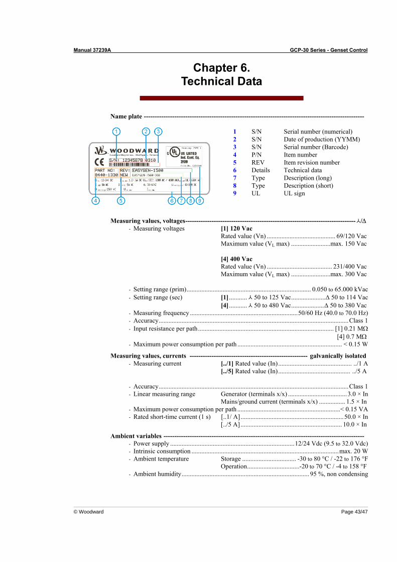
Manual 37239A GCP-30 Series - Genset Control
© Woodward Page 43/47
Chapter 6. Technical Data
Name plate -----------------------------------------------------------------------------------------------------
1 S/N Serial number (numerical) 2 S/N Date of production (YYMM) 3 S/N Serial number (Barcode) 4 P/N Item number 5 REV Item revision number 6 Details Technical data 7 Type Description (long) 8 Type Description (short) 9 UL UL sign
Measuring values, voltages------------------------------------------------------------------------------ /∆ - Measuring voltages [1] 120 Vac
Rated value (Vn) .......................................... 69/120 Vac Maximum value (VL max) ........................max. 150 Vac [4] 400 Vac Rated value (Vn) ........................................ 231/400 Vac Maximum value (VL max) ........................max. 300 Vac
- Setting range (prim)............................................................................ 0.050 to 65.000 kVac - Setting range (sec) [1] ........... 50 to 125 Vac.....................∆ 50 to 114 Vac [4] ........... 50 to 480 Vac....................∆ 50 to 380 Vac - Measuring frequency ..................................................................50/60 Hz (40.0 to 70.0 Hz) - Accuracy....................................................................................................................Class 1 - Input resistance per path................................................................................... [1] 0.21 MΩ
[4] 0.7 MΩ - Maximum power consumption per path ................................................................ < 0.15 W
Measuring values, currents ------------------------------------------------------ galvanically isolated - Measuring current [../1] Rated value (In)............................................. ../1 A
[../5] Rated value (In)............................................ ../5 A
- Accuracy....................................................................................................................Class 1 - Linear measuring range Generator (terminals x/x) .................................... 3.0 × In
Mains/ground current (terminals x/x) ................ 1.5 × In - Maximum power consumption per path ...............................................................< 0.15 VA - Rated short-time current (1 s) [..1/ A]...............................................................50.0 × In
[../5 A].............................................................. 10.0 × In
Ambient variables -------------------------------------------------------------------------------------------- - Power supply ............................................................................12/24 Vdc (9.5 to 32.0 Vdc) - Intrinsic consumption ..........................................................................................max. 20 W - Ambient temperature Storage ................................. -30 to 80 °C / -22 to 176 °F
Operation................................-20 to 70 °C / -4 to 158 °F - Ambient humidity.............................................................................. 95 %, non condensing
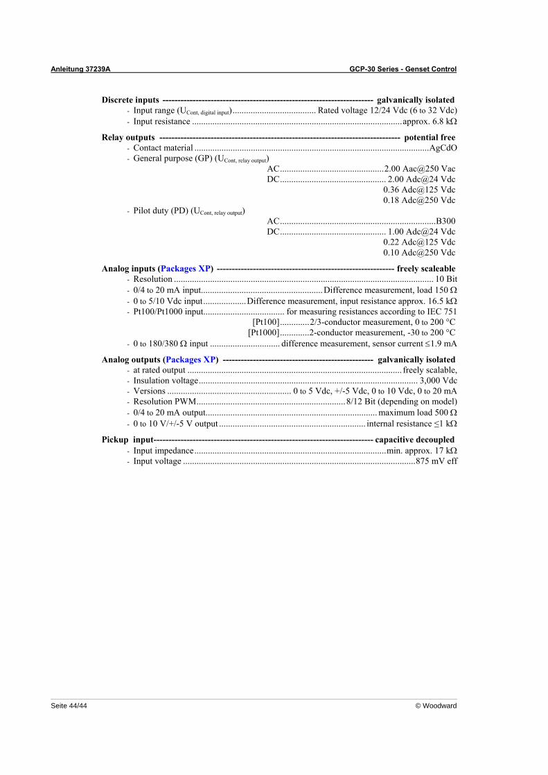
Anleitung 37239A GCP-30 Series - Genset Control
Seite 44/44 © Woodward
Discrete inputs ---------------------------------------------------------------------- galvanically isolated - Input range (UCont, digital input)..................................... Rated voltage 12/24 Vdc (6 to 32 Vdc) - Input resistance .............................................................................................approx. 6.8 kΩ
Relay outputs -------------------------------------------------------------------------------- potential free - Contact material ........................................................................................................AgCdO - General purpose (GP) (UCont, relay output)
AC..............................................2.00 Aac@250 Vac DC............................................... 2.00 Adc@24 Vdc 0.36 Adc@125 Vdc 0.18 Adc@250 Vdc
- Pilot duty (PD) (UCont, relay output) AC.....................................................................B300 DC............................................... 1.00 Adc@24 Vdc 0.22 Adc@125 Vdc 0.10 Adc@250 Vdc
Analog inputs (Packages XP) ----------------------------------------------------------- freely scaleable - Resolution ................................................................................................................... 10 Bit - 0/4 to 20 mA input......................................................Difference measurement, load 150 Ω - 0 to 5/10 Vdc input...................Difference measurement, input resistance approx. 16.5 kΩ - Pt100/Pt1000 input.................................... for measuring resistances according to IEC 751
[Pt100].............2/3-conductor measurement, 0 to 200 °C [Pt1000].............2-conductor measurement, -30 to 200 °C
- 0 to 180/380 Ω input ............................... difference measurement, sensor current ≤1.9 mA
Analog outputs (Packages XP) -------------------------------------------------- galvanically isolated - at rated output ............................................................................................... freely scalable, - Insulation voltage................................................................................................. 3,000 Vdc - Versions ....................................................... 0 to 5 Vdc, +/-5 Vdc, 0 to 10 Vdc, 0 to 20 mA - Resolution PWM..................................................................8/12 Bit (depending on model) - 0/4 to 20 mA output............................................................................ maximum load 500 Ω - 0 to 10 V/+/-5 V output ................................................................. internal resistance ≤1 kΩ
Pickup input------------------------------------------------------------------------- capacitive decoupled - Input impedance.....................................................................................min. approx. 17 kΩ - Input voltage .......................................................................................................875 mV eff
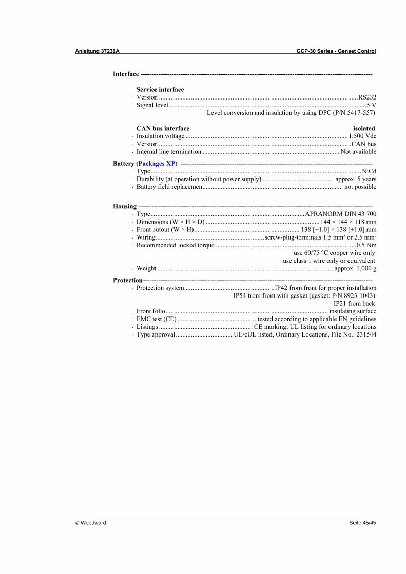
Anleitung 37239A GCP-30 Series - Genset Control
© Woodward Seite 45/45
Interface -------------------------------------------------------------------------------------------------------- Service interface
- Version .......................................................................................................................RS232 - Signal level ......................................................................................................................5 V
Level conversion and insulation by using DPC (P/N 5417-557) CAN bus interface isolated
- Insulation voltage .................................................................................................1,500 Vdc - Version ...................................................................................................................CAN bus - Internal line termination .................................................................................. Not available
Battery (Packages XP) -------------------------------------------------------------------------------------- - Type..............................................................................................................................NiCd - Durability (at operation without power supply) ........................................... approx. 5 years - Battery field replacement................................................................................... not possible
Housing --------------------------------------------------------------------------------------------------------- - Type............................................................................................APRANORM DIN 43 700 - Dimensions (W × H × D) ....................................................................144 × 144 × 118 mm - Front cutout (W × H)............................................................... 138 [+1.0] × 138 [+1.0] mm - Wiring.................................................................screw-plug-terminals 1.5 mm² or 2.5 mm² - Recommended locked torque ....................................................................................0.5 Nm
use 60/75 °C copper wire only use class 1 wire only or equivalent
- Weight ......................................................................................................... approx. 1,000 g
Protection------------------------------------------------------------------------------------------------------- - Protection system......................................................IP42 from front for proper installation
IP54 from front with gasket (gasket: P/N 8923-1043) IP21 from back
- Front folio................................................................................................. insulating surface - EMC test (CE) ............................................... tested according to applicable EN guidelines - Listings ........................................................ CE marking; UL listing for ordinary locations - Type approval.................................. UL/cUL listed, Ordinary Locations, File No.: 231544
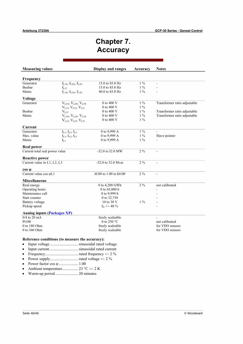
Anleitung 37239A GCP-30 Series - Genset Control
Seite 46/46 © Woodward
Chapter 7. Accuracy
Measuring values Display and ranges Accuracy Notes Frequency Generator fL1N, fL2N, fL3N 15.0 to 85.0 Hz 1 % - Busbar fL12 15.0 to 85.0 Hz 1 % - Mains fL1N, fL2N, fL3N 40.0 to 85.0 Hz 1 % -
Voltage Generator VL1N, VL2N, VL3N 0 to 400 V 1 % Transformer ratio adjustable VL12, VL23, VL31 0 to 400 V 1 % Busbar VL12 0 to 400 V 1 % Transformer ratio adjustable Mains VL1N, VL2N, VL3N 0 to 400 V 1 % Transformer ratio adjustable VL12, VL23, VL31 0 to 400 V 1 %
Current Generator IL1, IL2, IL3 0 to 9,999 A 1 % - Max. value IL1, IL2, IL3 0 to 9,999 A 1 % Slave pointer Mains IL1 0 to 9,999 A 1 % -
Real power Current total real power value -32.0 to 32.0 MW 2 % -
Reactive power Current value in L1, L2, L3 -32.0 to 32.0 Mvar 2 % -
cos φ Current value cos φL1 i0.00 to 1.00 to k0.00 2 % -
Miscellaneous Real energy 0 to 4,200 GWh 2 % not calibrated Operating hours 0 to 65,000 h - Maintenance call 0 to 9,999 h - Start counter 0 to 32,750 - Battery voltage 10 to 30 V 1 % - Pickup speed fN +/- 40 % -
Analog inputs (Packages XP) 0/4 to 20 mA freely scaleable - Pt100 0 to 250 °C not calibrated 0 to 180 Ohm freely scaleable for VDO sensors 0 to 360 Ohm freely scaleable for VDO sensors Reference conditions (to measure the accuracy): • Input voltage ............................ sinusoidal rated voltage • Input current............................. sinusoidal rated current • Frequency................................. rated frequency +/- 2 % • Power supply............................ rated voltage +/- 2 % • Power factor cos φ ................... 1.00 • Ambient temperature................ 23 °C +/- 2 K • Warm-up period ....................... 20 minutes

We appreciate your comments about the content of our publications.
Please send comments to: [email protected] Please include the manual number from the front cover of this publication.
Woodward Governor Company Leonhard-Reglerbau GmbH
Handwerkstrasse 29 - 70565 Stuttgart - Germany Phone +49 (0) 711 789 54-0 • Fax +49 (0) 711 789 54-100
Homepage
http://www.woodward.com/smart-power
Woodward has company-owned plants, subsidiaries, and branches, as well as authorized distributors and other authorized service and sales facilities throughout the world.
Complete address/phone/fax/e-mail information
for all locations is available on our website (www.woodward.com).
04/9/S