gc 35 tecnical reference manual
DESCRIPTION
sistema v caterpillarTRANSCRIPT

7172019 GC 35 Tecnical Reference Manual
httpslidepdfcomreaderfullgc-35-tecnical-reference-manual 123
7172019 GC 35 Tecnical Reference Manual
httpslidepdfcomreaderfullgc-35-tecnical-reference-manual 223
GC-35 Control BoxTechnical Reference Manual
Part Number 1001548-02
Rev A
copyCopyright Topcon Positioning Systems Inc
January 2014
All contents in this manual are copyrighted by Topcon Positioning Systems Inc All rights reserved
7172019 GC 35 Tecnical Reference Manual
httpslidepdfcomreaderfullgc-35-tecnical-reference-manual 323
7172019 GC 35 Tecnical Reference Manual
httpslidepdfcomreaderfullgc-35-tecnical-reference-manual 423
iPN 1001548-02
bull bull bull bull bull bull
Table of Contents
Preface iii
Terms and Conditions iii
Manual Conventions vIntroduction 1
Features 1
Powering the Control Box OnOff 2
Control Screen 2
Accessing the Technicianrsquos Menu 3
Technicianrsquos Menu 9
Configuration 10
Configuration Codes 10 Averaging 11
Valve Type 11
Proportional Current 11
Proportional Pulse Width Modulated 11
Solenoid 11
Danfoss 12
Valve Drive 12
Dither Amplitude 12Dither Frequency 12
Frequency 12
Max Current 12
Hour 13
External Auto 13
Auto Power (Paver Only) 13
Esup2 Reset 13
Lock Menu 14Lock Menu Settings 14
Elevation Gains (Raise and Lower) 14
Slope Gain 15
Valve Offsets (Raise and Lower) 15
Elevation Deadband 15
Slope Deadband 16
Working Window Adjustment 16
7172019 GC 35 Tecnical Reference Manual
httpslidepdfcomreaderfullgc-35-tecnical-reference-manual 523
iiPN 1001548-02
Slope Working Window 18
Smartlink (Elevation and Slope) 18
Warranty 19
7172019 GC 35 Tecnical Reference Manual
httpslidepdfcomreaderfullgc-35-tecnical-reference-manual 623
Preface iiGC-35 Control Box Technical Reference Manual PN 1001548-02
bull bull bull bull bull bull
Preface
Thank you for purchasing this Topcon product The materials available in this Manual (the ldquoManualrdquo) have been preparedby Topcon Positioning Systems Inc (ldquoTPSrdquo) for owners of Topcon products and are designed to assist owners with theuse of the product and its use is subject to these terms and conditions (the ldquoTerms and Conditionsrdquo)
Terms and Conditions
Use
This product is designed to be used by a professional The user should have a good knowledge of the safe use of theproduct and implement the types of safety procedures recommended by the local government protection agency for bothprivate use and commercial job sites
Copyrights
All information contained in this Manual is the intellectual property of and copyrighted material of TPS All rights arereserved Do not use access copy store display create derivative works of sell modify publish distribute or allow anythird party access to any graphics content information or data in this Manual without TPSrsquo express written consent andmay only use such information for the care and operation of the product The information and data in this Manual are avaluable asset of TPS and are developed by the expenditure of considerable work time and money and are the result oforiginal selection coordination and arrangement by TPS
Trademarks
HiPer SRtrade TRUtrade Magnettrade Pocket-3Dtrade Topconreg and Topcon Positioning Systemstrade are trademarks or registeredtrademarks of TPS Windowsreg is a registered trademark of Microsoft Corporation The Bluetoothreg word mark and logosare owned by Bluetooth SIG Inc and any use of such marks by Topcon Positioning Systems Inc is used under licenseOther product and company names mentioned herein may be trademarks of their respective owners
Disclaimer of Warranty
EXCEPT FOR ANY WARRANTIES IN AN APPENDIX OR A WARRANTY CARD ACCOMPANYING THE PRODUCT THIS MANUAL AND THE PRODUCT ARE PROVIDED ldquoAS-ISrdquo THERE ARE NO OTHER WARRANTIES TPS DISCLAIMS ANY IMPLIEDWARRANTY OF MERCHANTABILITY OR FITNESS FOR ANY PARTICULAR USE OR PURPOSE TPS AND ITS DISTRIBUTORSSHALL NOT BE LIABLE FOR TECHNICAL OR EDITORIAL ERRORS OR OMISSIONS CONTAINED HEREIN NOR FORINCIDENTAL OR CONSEQUENTIAL DAMAGES RESULTING FROM THE FURNISHING PERFORMANCE OR USE OF THIS
MATERIAL OR THE PRODUCT SUCH DISCLAIMED DAMAGES INCLUDE BUT ARE NOT LIMITED TO LOSS OF TIME LOSSOR DESTRUCTION OF DATA LOSS OF PROFIT SAVINGS OR REVENUE OR LOSS OF THE PRODUCTrsquoS USE IN ADDITIONTPS IS NOT RESPONSIBLE OR LIABLE FOR DAMAGES OR COSTS INCURRED IN CONNECTION WITH OBTAININGSUBSTITUTE PRODUCTS OR SOFTWARE CLAIMS BY OTHERS INCONVENIENCE OR ANY OTHER COSTS IN ANY EVENTTPS SHALL HAVE NO LIABILITY FOR DAMAGES OR OTHERWISE TO YOU OR ANY OTHER PERSON OR ENTITY IN EXCESSOF THE PURCHASE PRICE FOR THE PRODUCT
Please read the terms and conditions carefully
7172019 GC 35 Tecnical Reference Manual
httpslidepdfcomreaderfullgc-35-tecnical-reference-manual 723
erms and Conditions ivGC-35 Control Box Technical Reference Manual PN 1001548-02
License Agreement
Use of any computer programs or software supplied by TPS or downloaded from a TPS website (the ldquoSoftwarerdquo) inconnection with the product constitutes acceptance of these Terms and Conditions in this Manual and an agreementto abide by these Terms and Conditions The user is granted a personal non-exclusive non-transferable license touse such Software under the terms stated herein and in any case only with a single product You may not assign ortransfer the Software or this license without the express written consent of TPS This license is effective untilterminated You may terminate the license at any time by destroying the Software and Manual TPS may terminatethe license if you fail to comply with any of the Terms or Conditions You agree to destroy the Software and manual
upon termination of the use of the product All ownership copyright and other intellectual property rights in and tothe Software belong to TPS If these license terms are not acceptable return any unused software and manual
Confidentiality
This Manual its contents and the Software (collectively the ldquoConfidential Informationrdquo) are the confidential andproprietary information of TPS You agree to treat TPSrsquo Confidential Information with a degree of care no less stringentthat the degree of care you would use in safeguarding your own most valuable trade secrets Nothing in this paragraphshall restrict you from disclosing Confidential Information to your employees as may be necessary or appropriate tooperate or care for the product Such employees must also keep the Confidentiality Information confidential In theevent you become legally compelled to disclose any of the Confidential Information you shall give TPS immediatenotice so that it may seek a protective order or other appropriate remedy
Website Other Statements
No statement contained at the TPS website (or any other website) or in any other advertisements or TPS literatureor made by an employee or independent contractor of TPS modifies these Terms and Conditions (including theSoftware license warranty and limitation of liability)
Safety
Improper use of the product can lead to injury to persons or property andor malfunction of the product The productshould only be repaired by authorized TPS warranty service centers Users should review and heed the safety warnings
in an Appendix
Miscellaneous
The above Terms and Conditions may be amended modified superseded or canceled at any time by TPS The aboveTerms and Conditions will be governed by and construed in accordance with the laws of the State of Californiawithout reference to conflict of laws
7172019 GC 35 Tecnical Reference Manual
httpslidepdfcomreaderfullgc-35-tecnical-reference-manual 823
Manual Conventions vGC-35 Control Box Technical Reference Manual PN 1001548-02
Manual Conventions
This manual uses the following conventions
Convention Description Example
Bold Menu or drop-down menu item File Exit (Click the File menu and clickExit)
Name of a dialog box or screen From the Connection screen
Button or key commands Click Finish
Mono User supplied text or variable Type guest and click Enter
Italic Reference to another manual or help document Refer to the Topcon Reference Manual
Further information to note about system configuration maintenance or setup
Supplementary information that can have an adverse affect on system operation systemperformance data integrity measurements or personal safety
Notification that an action has the potential to result in system damage loss of data loss ofwarranty or personal injury
7172019 GC 35 Tecnical Reference Manual
httpslidepdfcomreaderfullgc-35-tecnical-reference-manual 923
Introduction 1GC-35 Control Box Technical Reference Manual PN 1001548-02
bull bull bull bull bull bull
Introduction
The Technicians Menu contains additional system menu items not available to the operator (end user) in the GC-35 Control Box Performance Menu
These menu items offer the ability to override default settings of the P-32 system to improve system performancein certain situations These menu items are not however meant to be changed by the operator
The following sections describe the features of the GC-35 control box and explain how to access the TechnicianrsquosMenu select a menu item save the new value and exit the Technicianrsquos Menu
Features
Figure 1 GC-35 Control Box
Access to the Technicianrsquos Menu is intended for and should be limited to Topcon qualified dealerand field service technicians Any changes to the factory default settings without a thoroughunderstanding to their effects on the P-32 system may cause adverse consequences to systemaccuracy and operation
Auto Indicator LED
Auto Button
Survey Button
Elevation Indicator
LED (Green)
Slope Indicator
LED (Yellow)
SlopeElevation
Button
Jog UpDown
Buttons
LCD
Light Sensor
Power OnOff
Button
Grade Adjustment
Knob
Grade Adjustment
Arrows
Menu Selection
Buttons
Grade Indicator
LEDs
USB Port
USB Cap
(Removed)
Jaw Mount
Power Connector
Sonic Tracker or Slope Sensor
Connectors
7172019 GC 35 Tecnical Reference Manual
httpslidepdfcomreaderfullgc-35-tecnical-reference-manual 1023
owering the Control Box OnOff 2GC-35 Control Box Technical Reference Manual PN 1001548-02
Powering the Control Box OnOff
Figure 2 Power OnOff
Control ScreenThe Control Screen displays when you power on the control box It is your interface with the components ofthe P-32 system The Control Screen changes depending on how you have configured the Control Box and theP-32 system
The illustration below shows an example of a Control Box set up to display information from a secondary ControlBox set up for Slope Control
Figure 3 Control Screen
Power OnOff
Button
Startup Screen Shutdown Screen
GC-35
Shutting Down
con1047297g 21
Elevation Set
Point Value
Actual Elevation
Sensor Reading
Slope Set Point Value
PositiveNegative
Slope Indicator Icon
Actual Slope
Sensor Reading
MenuSet
Button Function
Display Area
Elevation Icon
Units (ftincm)
ST-3 SurfaceStringline Mode Icon
Display Slope Box
Auto Icon
Slope Icon
Primary Control Box Display Area
Secondary Control Box
Display Area
Cross Communication
On-Grade Icon
7172019 GC 35 Tecnical Reference Manual
httpslidepdfcomreaderfullgc-35-tecnical-reference-manual 1123
ccessing the Technicianrsquos Menu 3GC-35 Control Box Technical Reference Manual PN 1001548-02
Accessing the Technicianrsquos Menu
1 From the Control Screen press the MenuSet button
2 Rotate the Grade Adjustment Knob to scroll through the menu selections displayed on the screen
3 Select Tech Menu and press and hold the Enter button for three (3) seconds to enter the
Technicianrsquos Menu
Figure 4 Accessing the Technicianrsquos Menu
Press MenuSet Button Turn Grade Adjustment Knob Press and Hold
Enter Button for 3 Seconds
7172019 GC 35 Tecnical Reference Manual
httpslidepdfcomreaderfullgc-35-tecnical-reference-manual 1223
Technicianrsquos Menu 9GC-35 Control Box Technical Reference Manual PN 1001548-02
bull bull bull bull bull bull
Technicianrsquos Menu
This chapter describes the Technicianrsquos Menu items and their default factory settings
Table 1 lists the available menus
Table 1 Technicianrsquos Menu Settings
Menu Item Range Default Factory Setting
Configuration External 0ndash31 Custom External
Averaging 1 ndash 100 50
Valve Type Solenoid ProportionalDanfoss Pulse WidthModulated
Proportional
Valve Drive Sink Source Sink
Dither Amplitude 0ndash15 4
Dither Frequency 0ndash105 42
Frequency 1ndash13Hz
225ndash1950Hz
5Hz
Max Current 067ndash48 Amps 175 Amps
Hour Read only Hours 00
Hours Auto 00
External Auto On Off Invert Off
Auto Power Up (Paver only) On Off On
Esup2 Reset Cancel Reset Cancel
Lock Menu Level 1 - Unlocked
Level 2 - Moderate
Level 3 - Restricted
Level 1 - Unlocked
Elevation Gains Raise 1 ndash 200 Raise 25
Lower 1 ndash 200 Lower 25
Slope Gain 1 ndash 100 25
Valve Offsets Raise 1 ndash 999 Raise 135
Lower 1 ndash 999 Lower 135
Elevation Deadband 1 ndash 30 mm 3 mm
Slope Deadband 0025 ndash 075 0075
Working Window 0ndash500 Off 020 ft
Slope Working Window 01-100 20
Smartlink Slope 0 - 100 Slope 0
Elevation 0 - 100 Elevation 0
7172019 GC 35 Tecnical Reference Manual
httpslidepdfcomreaderfullgc-35-tecnical-reference-manual 1323
onfiguration 10GC-35 Control Box Technical Reference Manual PN 1001548-02
Configuration
This setting selects a valve drive configuration and has up to 32 preprogrammed configurations to select from You may also create a custom configuration
Configuration Value Range External 0-31 Custom
Default External
bull External ndash Upon power up the control box looks for an external configuration resistor between pins Land K of the 11 pin bulkhead connector and defaults to the listed configuration table for valve control
The configuration number displays on the control box LCD when the box is turned onbull Value between 0-31 ndash The control box defaults to the valve control parameters for this number listed inthe configuration chart (see Table 2 on page 10) The configuration number displays on the control boxLCD when the box is turned on
bull Custom ndash Create a custom valve control configuration by setting the Valve Type Current DirectionCurrent Limit Frequency (for PWM modes and Solenoid) Dither Amplitude (except Solenoid mode) andDither Frequency (except Solenoid mode)
Configuration Codes
Table 2 lists available configurations
Table 2 Configuration Codes
ConfigResistor
(ohms)
Drive Type Current Direction Dither Amplitude Dither Freq Freq Hz Current Limit
0 0 Sol Sink None None Adj None
1 77
2 160
3 249
4 341
5 441 Sol Source None None Adj None
6 560 Sol Source None None Adj None
7 670
8 800 Sol Source None None Adj None
9 940 Sol Source None None Adj None10 1100 Sol Sink None None Adj None
11 1260 Sol Source None None Adj
12 1445
14 1890
15 2140 Pro Cur Source 6 42 NA 175A
17 2760 Sol Sink None None Adj None
18 3140 Sol Sink None None Adj None
19 3583 Sol Source None None Adj None
20 4104 Sol Sink None None Adj None
21 4725 Sol Sink None None Adj None
22 5480 Sol
23 6414
26 11310 Sol Source None None Adj None
27 14440
28 19440
29 28670
30 51500 Pro Cur Source 12 42 NA 175A
31 open Pro Cur Sink 6 42 NA 175A
7172019 GC 35 Tecnical Reference Manual
httpslidepdfcomreaderfullgc-35-tecnical-reference-manual 1423
veraging 11GC-35 Control Box Technical Reference Manual PN 1001548-02
Averaging
Averaging changes the amount of dampening or filtering applied to the laser receiver or elevation sensormeasurements Averaging can be thought of as the time period over which a running average of the elevationmeasurement is calculated
Averaging Value Range 1ndash100
Default 50
A lower value averages fewer elevation measurements allowing the system to react more quickly to grade
changes
A larger value averages more elevation measurements making the system less reactive to fluctuations in gradesuch as with laser ldquobeam bouncerdquo on windy days
Valve Type
Valve Type allows you to select the type of valves used on your machine
Valve Type Value Range Solenoid Servo Proportional Danfoss Pulse PWMDefault Proportional
The following sections describe each of these valve types
Proportional Current
Proportional Current provides a current regulated proportional output and is the preferred setting forproportional valves
A percentage of the total current setting is calculated based on the gain setting and given grade correctionProportional Current control applies full machine voltage to the valve coil until the desired current is reachedthen the voltage is turned off When the current drops below the desired value the process is repeated
Proportional Pulse Width Modulated
Proportional Pulse Width Modulated provides a pulse width regulated proportional output
A percentage of the total duty cycle is calculated based on the gain setting and the given grade correction PulseWidth Modulation cycles the output voltage on and off at the desired duty cycle
Solenoid
Solenoid operates the same as PWM mode except set up specifically for the lower frequency solenoid valves
Danfoss
Danfoss provides a proportional voltage output to drive the specific requirements of the Danfoss brand ofproportional valves In this mode switched power (Vsw) and ground connect to the Danfoss valve through thevalve cable and the Raise output pin of the control box controls the reference signal to the valve In a neutral(no grade) correction output the reference signal is held at half of the switched voltage For example if a 12volt system produced 13 volts on the Vsw line 65 volts are held on the reference output for a no correctionsignal
bull For a raise correction signal the control box increases the reference voltage from 65 to a maximum of975 V
Averaging does not affect slope control
7172019 GC 35 Tecnical Reference Manual
httpslidepdfcomreaderfullgc-35-tecnical-reference-manual 1523
alve Drive 12GC-35 Control Box Technical Reference Manual PN 1001548-02
bull For a lower output signal the control box decreases the reference voltage to a minimum of 325 V
Valve Drive
Valve Drive selects the current direction of the valves on the machine
Valve Drive Value Range Sink Source
Select Sink if the valve has a permanent positive connection and needs a switched negative connection (thecontrol box sinks current)
Select Source if the valve has a permanent ground (negative) connection and needs a switched positiveconnection (the control box sources current)
Dither Amplitude
Dither Amplitude allows you to select the amount of dither to apply to the valve
Dither is a continuous low frequency ldquopulserdquo applied to the valve drive signal for proportional valves to keep thevalversquos spool from sticking
Dither Amplitude Value Range 0ndash15
Dither Amplitude is a percentage of full current for the Proportional Current valve type or duty cycle for thePWM valve type Dither does not apply for Solenoid Danfoss or Servo valve types
Dither Frequency
Dither Frequency adjusts the frequency of the dither in cycles per second
Dither Frequency Value Range 0ndash105 Hz
Frequency
Frequency adjusts the number of pulses sent to control valves in one secondFrequency Value Range 1ndash13 Hz 225ndash1950 Hz
The frequency value is adjustable from 1 to 13 Hz for Solenoid valves On Pulse Width Modulated mode valvesthe range is 225 to 1950 Hz
Max Current
Max Current adjusts the maximum valve drive current that the control box outputs when using ProportionalCurrent valve output mode and the over-current trip level for other valve types
Current Limit Value Range 067ndash48 Amps
If a Danfoss valve sees a reference voltage greater than 75 of Vsw or below 25 of Vsw the valvedefaults to an ldquoerrorrdquo state and the valve is held in the neutral position
Frequency does not apply for Proportional Current and Danfoss valve types
Changing the Frequency has an effect on the Offset Check the Offset after changing theFrequency
7172019 GC 35 Tecnical Reference Manual
httpslidepdfcomreaderfullgc-35-tecnical-reference-manual 1623
our 13GC-35 Control Box Technical Reference Manual PN 1001548-02
Hour
Hour displays the amount of hours the control box has been operating and the amount of hours the control boxhas been operating in Automatic
Hour Settings No settings (read only)
External Auto
External Auto disables or enables an external automanual switch
External Auto Settings OnOffInvert
If On is selected the system requires both an external AM switch and activation of the Control Boxrsquos Autobutton to switch the system in and out of Automatic control Activate the external AM switch by connectingpin E of the 11 PIN bulkhead to ground
If you select Invert connecting pin E to ground takes the system out of Automatic control Automatic controlactivates only when pin E is connected to power such as when connecting to an in-motion switch
Auto Power (Paver Only)
The Auto Power setting allows the system to automatically power up to the last used mode
Auto Power Settings OnOff
When the Auto Power setting is On the system powers up in the last mode seen before power down (Auto orManual) For example the paver is in automatic control is shut down and then powered up once more Thepaver is now ready to pave in Auto
When the Auto Power setting is Off the operator must press the Auto button to return to Auto after a powerdown
Esup2 Reset
Esup2 Reset reconfigures the system to factory settings
Esup2 Reset Settings Range CancelReset
To reset all settings in the Performance Menu and the Technician Menu to factory defaults select Reset and press and hold the Enter button for three (3) seconds
To cancel and return to the previous screen select Cancel
Lock Menu
The Lock-Out Setting allows certain Performance Settings in the Performance Menu to be made inaccessibleto the operator (see ldquoPaver Lock Menu Settingsrdquo on page 14)
If the Auto Power setting is On the machine powers up in Auto any time it was shut down in AutoOnly use Auto Power On in asphalt paver applications
Setting Auto Power to On for a machine other than asphalt pavers is not recommended Seriousinjury to operators or bystanders from unexpected machine movement could result
If you select Reset the Control Box reverts your custom Control Box settings back to their factorydefault values
7172019 GC 35 Tecnical Reference Manual
httpslidepdfcomreaderfullgc-35-tecnical-reference-manual 1723
levation Gains (Raise and Lower) 14GC-35 Control Box Technical Reference Manual PN 1001548-02
Lock-Out Value Range Level 1 - Unlocked Level2 - Moderate Level 3 - Restricted
bull Level 1 ndash all Performance Menu items are accessible to the operator
bull Level 2ndash some items no longer appear in the Performance Menu and are only accessible in theTechnicianrsquos Menu
bull Level 3 ndash additional items no longer appear in the Performance Menu and are only accessible in theTechnicianrsquos Menu
Lock Menu Settings
Table 3 lists the settings that can be locked out (made unavailable)
Elevation Gains (Raise and Lower)
Elevation Gains determines the speed at which your Topcon P-32 System allows the tow point cylinders to adjustto a change in elevation For faster hydraulic response increase the gain value For slower hydraulic responsedecrease the gain value
The objective is to set the gain so the screed reacts to the change in grade quickly but without ldquoovershootingrdquothe new elevation
Gain Elevation Value Range 1-200
Table 3 Paver Lock Menu Settings
Performance Menu Item Level 1 - Unlocked Level 2 - Moderate Level 3 - Restricted
1 Elevation Gains Available Available Locked
2 Slope Gain Available Available Locked
3 Valve Offsets Available Available Locked
4 Elevation Deadband Available Locked Locked
5 Slope Deadband Available Locked Locked
6 Averaging Available Locked Locked
7 Machine Type Available Available Available
8 Display Available Available Available
9 Units Available Available Available
10 System Info Available Available Available
11 Sonic Tracker 3 Available Available Available
12 Slope Resolution Available Available Available
13 Slope Cal Block Available Available Locked
14 Tech Menu Available Available Available
Before setting the Elevation Gain make sure the machines hydraulic flow controls valves are adjustedfor proper cylinder speed according to the manufacturers recommendations
7172019 GC 35 Tecnical Reference Manual
httpslidepdfcomreaderfullgc-35-tecnical-reference-manual 1823
lope Gain 15GC-35 Control Box Technical Reference Manual PN 1001548-02
Slope Gain
This setting determines the speed at which your Topcon P-32 System allows the tow point cylinders to adjustto a change in slope For faster hydraulic response increase the gain value For slower hydraulic responsedecrease the gain value
The objective is to set the gain so the screed reacts to the change in grade quickly but without ldquoovershootingrdquoOn-Grade Slope Gain should not be set at a higher value than the Elevation Gain on the other side of the paver
Gain Elevation Value Range 1-100
Valve Offsets (Raise and Lower)
Valve Offsets is the minimum amount of electrical signals sent to the valve which causes the hydraulic cylinderto move If the valve offset is too small the sensor will not reach On-Grade Likewise if the valve offset valueis too large the sensor will move too much and overshoot On-Grade
Run the Paver until the hydraulic oil is at normal operating temperature before setting the valve offsets Oncethey are set you should not need to readjust the valve offsets unless the Control Box is moved to a new paveror the hydraulic performance changes
Valve Offset Value Range (Raise and Lower) 1 - 999
Elevation Deadband
Elevation Deadband is the area of the Working Window that is On-Grade While the reference is within that areathe paverrsquos valves are idle (closed) Therefore the wider the Elevation Deadband (On-Grade area) the more areference can move up or down without a correction being initiated Once the signal from the reference is outof the deadband your control box drives the hydraulics to place the reference back in the center of thedeadband
Deadband Elevation Value Range 1ndash30 mm
Before setting the Slope Gain ensure the machines hydraulic flow control valves are adjusted forproper cylinder speed according to the manufacturers recommendations
Do not set slope gain at a higher value than the elevation gain on the other side of the paver A highervalue may cause the slope to be over reactive
Set the Valve Offsets before adjusting elevation and slope gains and averaging
The offset value on one side of the paver may differ from the offset value on the other side of thepaver You must verify the offset values before swapping boxes Use the ldquoLeftrdquo and ldquoRightrdquo labelsprovided
Never attempt to use Valve Offsets to compensate for a slower raise or lower speed of your hydraulicvalves as it causes undershooting or overshooting in Slope Mode and can adversely affect the qualityof the mat
Select the amount of Elevation Deadband carefully Too small of an Elevation Deadband causes thetow point cylinder to constantly hunt up and down while the sensor tries to find On-Grade Too largeof an Elevation Deadband does not allow the sensor to send grade corrections to the values causingunwanted variations in mat thickness
7172019 GC 35 Tecnical Reference Manual
httpslidepdfcomreaderfullgc-35-tecnical-reference-manual 1923
lope Deadband 16GC-35 Control Box Technical Reference Manual PN 1001548-02
Slope Deadband
Slope Deadband defines the size of the on-grade area where no valve corrections are made
Deadband Slope Value Range 0025ndash075
The wider the Slope Deadband the greater the slope can vary without initiating a correction
For example if the operator is grading at a 20 slope and the Slope Deadband is set at 10 the system
reads on-grade anywhere from 195 slope to 205 slope The lower the percentage the tighter the SlopeDeadband
Once the slope signal is out of the Slope Deadband System Five drives the hydraulics back within the SlopeDeadband
Working Window Adjustment
Working Window Adjustment adjusts the working window of the sonic tracker (Figure 5)
Working Window Settings 0ndash500 Off
Default 020
The default setting is 020 which gives 020 ft (61 mm) above and below on-grade Setting the value to Offcompletely disables the working window and allows any target to be seen
7172019 GC 35 Tecnical Reference Manual
httpslidepdfcomreaderfullgc-35-tecnical-reference-manual 2023
lope Working Window 17GC-35 Control Box Technical Reference Manual PN 1001548-02
Figure 5 Sonic Tracker Working Window
Slope Working Window
Slope Working Window adjusts the working window of the Slope Sensor (Figure 6)
Slope Working Window Value Range 01 - 100 Off
Default 20
The default setting is 20 which gives 20 slope above and below ongrade Setting the value to Off completelydisables the working window
Out of Range
Ongrade
Flashing UpDown Arrow
Solid UpDown Arrow
20rsquo
20rsquo
20rsquo
20rsquo
Working
Window
(Adjustable)
ST-3 Sonic Tracker II
When using the Sonic Tracker II to follow a stringline curb or other elevated reference there is adanger of making an unwanted cut if the Trackerrsquos sonic cone moves away from the target This canoccur if the working window is either off or set as high as the distance between the reference and theground Setting the working window to the default value of 20 (020ft) prevents the automatic controlfrom making such a reaction due to a loss of the target
7172019 GC 35 Tecnical Reference Manual
httpslidepdfcomreaderfullgc-35-tecnical-reference-manual 2123
martlink (Elevation and Slope) 18GC-35 Control Box Technical Reference Manual PN 1001548-02
Figure 6 Slope Working Window
Smartlink (Elevation and Slope)
Smartlink allows the Control Box to send a percentage of the slopeelevation correction on one side of themachine to the Control Box on the other side of the machine preemptively raising or lowering that hydrauliccylinder to keep the machine at the correct grade Smartlink decreases the lag in correction that can occur onone side of the machine as the second Control Box begins moving the valve without having to wait for thesensor on the other side of the machine to detect and correct for a change in elevationslope
Smartlink Value Range 0 - 100
Default 0
Out of Range
Working Window (Adjustable)
Ongrade
20
20
Ongrade
20
20
7172019 GC 35 Tecnical Reference Manual
httpslidepdfcomreaderfullgc-35-tecnical-reference-manual 2223
Warranty 19GC-35 Control Box Technical Reference Manual PN 1001548-02
bull bull bull bull bull bull
Warranty
Topcon laser and electronic positioning equipment are guaranteed against defective material and workmanshipunder normal use and application consistent with this Manual The equipment is guaranteed for the period indicatedon the warranty card accompanying the product starting from the date that the product is sold to the originalpurchaser by Topconrsquos Authorized Dealers1
During the warranty period Topcon will at its option repair or replace this product at no additional charge Repairparts and replacement products will be furnished on an exchange basis and will be either reconditioned or new Thislimited warranty does not include service to repair damage to the product resulting from an accident disastermisuses abuse or modification of the product
Warranty service may be obtained from an authorized Topcon warranty service dealer If this product is deliveredby mail purchaser agrees to insure the product or assume the risk of loss or damage in transit to prepay shippingcharges to the warranty service location and to use the original shipping container or equivalent A letter shouldaccompany the package furnishing a description of the problem andor defect
The purchaserrsquos sole remedy shall be replacement as provided above In no event shall Topcon be liable for anydamages or other claim including any claim for lost profits lost savings or other incidental or consequential damagesarising out of the use of or inability to use the product
1 The warranty against defects in a Topcon battery charger or cable is 90 days
7172019 GC 35 Tecnical Reference Manual
httpslidepdfcomreaderfullgc-35-tecnical-reference-manual 2323
7172019 GC 35 Tecnical Reference Manual
httpslidepdfcomreaderfullgc-35-tecnical-reference-manual 223
GC-35 Control BoxTechnical Reference Manual
Part Number 1001548-02
Rev A
copyCopyright Topcon Positioning Systems Inc
January 2014
All contents in this manual are copyrighted by Topcon Positioning Systems Inc All rights reserved
7172019 GC 35 Tecnical Reference Manual
httpslidepdfcomreaderfullgc-35-tecnical-reference-manual 323
7172019 GC 35 Tecnical Reference Manual
httpslidepdfcomreaderfullgc-35-tecnical-reference-manual 423
iPN 1001548-02
bull bull bull bull bull bull
Table of Contents
Preface iii
Terms and Conditions iii
Manual Conventions vIntroduction 1
Features 1
Powering the Control Box OnOff 2
Control Screen 2
Accessing the Technicianrsquos Menu 3
Technicianrsquos Menu 9
Configuration 10
Configuration Codes 10 Averaging 11
Valve Type 11
Proportional Current 11
Proportional Pulse Width Modulated 11
Solenoid 11
Danfoss 12
Valve Drive 12
Dither Amplitude 12Dither Frequency 12
Frequency 12
Max Current 12
Hour 13
External Auto 13
Auto Power (Paver Only) 13
Esup2 Reset 13
Lock Menu 14Lock Menu Settings 14
Elevation Gains (Raise and Lower) 14
Slope Gain 15
Valve Offsets (Raise and Lower) 15
Elevation Deadband 15
Slope Deadband 16
Working Window Adjustment 16
7172019 GC 35 Tecnical Reference Manual
httpslidepdfcomreaderfullgc-35-tecnical-reference-manual 523
iiPN 1001548-02
Slope Working Window 18
Smartlink (Elevation and Slope) 18
Warranty 19
7172019 GC 35 Tecnical Reference Manual
httpslidepdfcomreaderfullgc-35-tecnical-reference-manual 623
Preface iiGC-35 Control Box Technical Reference Manual PN 1001548-02
bull bull bull bull bull bull
Preface
Thank you for purchasing this Topcon product The materials available in this Manual (the ldquoManualrdquo) have been preparedby Topcon Positioning Systems Inc (ldquoTPSrdquo) for owners of Topcon products and are designed to assist owners with theuse of the product and its use is subject to these terms and conditions (the ldquoTerms and Conditionsrdquo)
Terms and Conditions
Use
This product is designed to be used by a professional The user should have a good knowledge of the safe use of theproduct and implement the types of safety procedures recommended by the local government protection agency for bothprivate use and commercial job sites
Copyrights
All information contained in this Manual is the intellectual property of and copyrighted material of TPS All rights arereserved Do not use access copy store display create derivative works of sell modify publish distribute or allow anythird party access to any graphics content information or data in this Manual without TPSrsquo express written consent andmay only use such information for the care and operation of the product The information and data in this Manual are avaluable asset of TPS and are developed by the expenditure of considerable work time and money and are the result oforiginal selection coordination and arrangement by TPS
Trademarks
HiPer SRtrade TRUtrade Magnettrade Pocket-3Dtrade Topconreg and Topcon Positioning Systemstrade are trademarks or registeredtrademarks of TPS Windowsreg is a registered trademark of Microsoft Corporation The Bluetoothreg word mark and logosare owned by Bluetooth SIG Inc and any use of such marks by Topcon Positioning Systems Inc is used under licenseOther product and company names mentioned herein may be trademarks of their respective owners
Disclaimer of Warranty
EXCEPT FOR ANY WARRANTIES IN AN APPENDIX OR A WARRANTY CARD ACCOMPANYING THE PRODUCT THIS MANUAL AND THE PRODUCT ARE PROVIDED ldquoAS-ISrdquo THERE ARE NO OTHER WARRANTIES TPS DISCLAIMS ANY IMPLIEDWARRANTY OF MERCHANTABILITY OR FITNESS FOR ANY PARTICULAR USE OR PURPOSE TPS AND ITS DISTRIBUTORSSHALL NOT BE LIABLE FOR TECHNICAL OR EDITORIAL ERRORS OR OMISSIONS CONTAINED HEREIN NOR FORINCIDENTAL OR CONSEQUENTIAL DAMAGES RESULTING FROM THE FURNISHING PERFORMANCE OR USE OF THIS
MATERIAL OR THE PRODUCT SUCH DISCLAIMED DAMAGES INCLUDE BUT ARE NOT LIMITED TO LOSS OF TIME LOSSOR DESTRUCTION OF DATA LOSS OF PROFIT SAVINGS OR REVENUE OR LOSS OF THE PRODUCTrsquoS USE IN ADDITIONTPS IS NOT RESPONSIBLE OR LIABLE FOR DAMAGES OR COSTS INCURRED IN CONNECTION WITH OBTAININGSUBSTITUTE PRODUCTS OR SOFTWARE CLAIMS BY OTHERS INCONVENIENCE OR ANY OTHER COSTS IN ANY EVENTTPS SHALL HAVE NO LIABILITY FOR DAMAGES OR OTHERWISE TO YOU OR ANY OTHER PERSON OR ENTITY IN EXCESSOF THE PURCHASE PRICE FOR THE PRODUCT
Please read the terms and conditions carefully
7172019 GC 35 Tecnical Reference Manual
httpslidepdfcomreaderfullgc-35-tecnical-reference-manual 723
erms and Conditions ivGC-35 Control Box Technical Reference Manual PN 1001548-02
License Agreement
Use of any computer programs or software supplied by TPS or downloaded from a TPS website (the ldquoSoftwarerdquo) inconnection with the product constitutes acceptance of these Terms and Conditions in this Manual and an agreementto abide by these Terms and Conditions The user is granted a personal non-exclusive non-transferable license touse such Software under the terms stated herein and in any case only with a single product You may not assign ortransfer the Software or this license without the express written consent of TPS This license is effective untilterminated You may terminate the license at any time by destroying the Software and Manual TPS may terminatethe license if you fail to comply with any of the Terms or Conditions You agree to destroy the Software and manual
upon termination of the use of the product All ownership copyright and other intellectual property rights in and tothe Software belong to TPS If these license terms are not acceptable return any unused software and manual
Confidentiality
This Manual its contents and the Software (collectively the ldquoConfidential Informationrdquo) are the confidential andproprietary information of TPS You agree to treat TPSrsquo Confidential Information with a degree of care no less stringentthat the degree of care you would use in safeguarding your own most valuable trade secrets Nothing in this paragraphshall restrict you from disclosing Confidential Information to your employees as may be necessary or appropriate tooperate or care for the product Such employees must also keep the Confidentiality Information confidential In theevent you become legally compelled to disclose any of the Confidential Information you shall give TPS immediatenotice so that it may seek a protective order or other appropriate remedy
Website Other Statements
No statement contained at the TPS website (or any other website) or in any other advertisements or TPS literatureor made by an employee or independent contractor of TPS modifies these Terms and Conditions (including theSoftware license warranty and limitation of liability)
Safety
Improper use of the product can lead to injury to persons or property andor malfunction of the product The productshould only be repaired by authorized TPS warranty service centers Users should review and heed the safety warnings
in an Appendix
Miscellaneous
The above Terms and Conditions may be amended modified superseded or canceled at any time by TPS The aboveTerms and Conditions will be governed by and construed in accordance with the laws of the State of Californiawithout reference to conflict of laws
7172019 GC 35 Tecnical Reference Manual
httpslidepdfcomreaderfullgc-35-tecnical-reference-manual 823
Manual Conventions vGC-35 Control Box Technical Reference Manual PN 1001548-02
Manual Conventions
This manual uses the following conventions
Convention Description Example
Bold Menu or drop-down menu item File Exit (Click the File menu and clickExit)
Name of a dialog box or screen From the Connection screen
Button or key commands Click Finish
Mono User supplied text or variable Type guest and click Enter
Italic Reference to another manual or help document Refer to the Topcon Reference Manual
Further information to note about system configuration maintenance or setup
Supplementary information that can have an adverse affect on system operation systemperformance data integrity measurements or personal safety
Notification that an action has the potential to result in system damage loss of data loss ofwarranty or personal injury
7172019 GC 35 Tecnical Reference Manual
httpslidepdfcomreaderfullgc-35-tecnical-reference-manual 923
Introduction 1GC-35 Control Box Technical Reference Manual PN 1001548-02
bull bull bull bull bull bull
Introduction
The Technicians Menu contains additional system menu items not available to the operator (end user) in the GC-35 Control Box Performance Menu
These menu items offer the ability to override default settings of the P-32 system to improve system performancein certain situations These menu items are not however meant to be changed by the operator
The following sections describe the features of the GC-35 control box and explain how to access the TechnicianrsquosMenu select a menu item save the new value and exit the Technicianrsquos Menu
Features
Figure 1 GC-35 Control Box
Access to the Technicianrsquos Menu is intended for and should be limited to Topcon qualified dealerand field service technicians Any changes to the factory default settings without a thoroughunderstanding to their effects on the P-32 system may cause adverse consequences to systemaccuracy and operation
Auto Indicator LED
Auto Button
Survey Button
Elevation Indicator
LED (Green)
Slope Indicator
LED (Yellow)
SlopeElevation
Button
Jog UpDown
Buttons
LCD
Light Sensor
Power OnOff
Button
Grade Adjustment
Knob
Grade Adjustment
Arrows
Menu Selection
Buttons
Grade Indicator
LEDs
USB Port
USB Cap
(Removed)
Jaw Mount
Power Connector
Sonic Tracker or Slope Sensor
Connectors
7172019 GC 35 Tecnical Reference Manual
httpslidepdfcomreaderfullgc-35-tecnical-reference-manual 1023
owering the Control Box OnOff 2GC-35 Control Box Technical Reference Manual PN 1001548-02
Powering the Control Box OnOff
Figure 2 Power OnOff
Control ScreenThe Control Screen displays when you power on the control box It is your interface with the components ofthe P-32 system The Control Screen changes depending on how you have configured the Control Box and theP-32 system
The illustration below shows an example of a Control Box set up to display information from a secondary ControlBox set up for Slope Control
Figure 3 Control Screen
Power OnOff
Button
Startup Screen Shutdown Screen
GC-35
Shutting Down
con1047297g 21
Elevation Set
Point Value
Actual Elevation
Sensor Reading
Slope Set Point Value
PositiveNegative
Slope Indicator Icon
Actual Slope
Sensor Reading
MenuSet
Button Function
Display Area
Elevation Icon
Units (ftincm)
ST-3 SurfaceStringline Mode Icon
Display Slope Box
Auto Icon
Slope Icon
Primary Control Box Display Area
Secondary Control Box
Display Area
Cross Communication
On-Grade Icon
7172019 GC 35 Tecnical Reference Manual
httpslidepdfcomreaderfullgc-35-tecnical-reference-manual 1123
ccessing the Technicianrsquos Menu 3GC-35 Control Box Technical Reference Manual PN 1001548-02
Accessing the Technicianrsquos Menu
1 From the Control Screen press the MenuSet button
2 Rotate the Grade Adjustment Knob to scroll through the menu selections displayed on the screen
3 Select Tech Menu and press and hold the Enter button for three (3) seconds to enter the
Technicianrsquos Menu
Figure 4 Accessing the Technicianrsquos Menu
Press MenuSet Button Turn Grade Adjustment Knob Press and Hold
Enter Button for 3 Seconds
7172019 GC 35 Tecnical Reference Manual
httpslidepdfcomreaderfullgc-35-tecnical-reference-manual 1223
Technicianrsquos Menu 9GC-35 Control Box Technical Reference Manual PN 1001548-02
bull bull bull bull bull bull
Technicianrsquos Menu
This chapter describes the Technicianrsquos Menu items and their default factory settings
Table 1 lists the available menus
Table 1 Technicianrsquos Menu Settings
Menu Item Range Default Factory Setting
Configuration External 0ndash31 Custom External
Averaging 1 ndash 100 50
Valve Type Solenoid ProportionalDanfoss Pulse WidthModulated
Proportional
Valve Drive Sink Source Sink
Dither Amplitude 0ndash15 4
Dither Frequency 0ndash105 42
Frequency 1ndash13Hz
225ndash1950Hz
5Hz
Max Current 067ndash48 Amps 175 Amps
Hour Read only Hours 00
Hours Auto 00
External Auto On Off Invert Off
Auto Power Up (Paver only) On Off On
Esup2 Reset Cancel Reset Cancel
Lock Menu Level 1 - Unlocked
Level 2 - Moderate
Level 3 - Restricted
Level 1 - Unlocked
Elevation Gains Raise 1 ndash 200 Raise 25
Lower 1 ndash 200 Lower 25
Slope Gain 1 ndash 100 25
Valve Offsets Raise 1 ndash 999 Raise 135
Lower 1 ndash 999 Lower 135
Elevation Deadband 1 ndash 30 mm 3 mm
Slope Deadband 0025 ndash 075 0075
Working Window 0ndash500 Off 020 ft
Slope Working Window 01-100 20
Smartlink Slope 0 - 100 Slope 0
Elevation 0 - 100 Elevation 0
7172019 GC 35 Tecnical Reference Manual
httpslidepdfcomreaderfullgc-35-tecnical-reference-manual 1323
onfiguration 10GC-35 Control Box Technical Reference Manual PN 1001548-02
Configuration
This setting selects a valve drive configuration and has up to 32 preprogrammed configurations to select from You may also create a custom configuration
Configuration Value Range External 0-31 Custom
Default External
bull External ndash Upon power up the control box looks for an external configuration resistor between pins Land K of the 11 pin bulkhead connector and defaults to the listed configuration table for valve control
The configuration number displays on the control box LCD when the box is turned onbull Value between 0-31 ndash The control box defaults to the valve control parameters for this number listed inthe configuration chart (see Table 2 on page 10) The configuration number displays on the control boxLCD when the box is turned on
bull Custom ndash Create a custom valve control configuration by setting the Valve Type Current DirectionCurrent Limit Frequency (for PWM modes and Solenoid) Dither Amplitude (except Solenoid mode) andDither Frequency (except Solenoid mode)
Configuration Codes
Table 2 lists available configurations
Table 2 Configuration Codes
ConfigResistor
(ohms)
Drive Type Current Direction Dither Amplitude Dither Freq Freq Hz Current Limit
0 0 Sol Sink None None Adj None
1 77
2 160
3 249
4 341
5 441 Sol Source None None Adj None
6 560 Sol Source None None Adj None
7 670
8 800 Sol Source None None Adj None
9 940 Sol Source None None Adj None10 1100 Sol Sink None None Adj None
11 1260 Sol Source None None Adj
12 1445
14 1890
15 2140 Pro Cur Source 6 42 NA 175A
17 2760 Sol Sink None None Adj None
18 3140 Sol Sink None None Adj None
19 3583 Sol Source None None Adj None
20 4104 Sol Sink None None Adj None
21 4725 Sol Sink None None Adj None
22 5480 Sol
23 6414
26 11310 Sol Source None None Adj None
27 14440
28 19440
29 28670
30 51500 Pro Cur Source 12 42 NA 175A
31 open Pro Cur Sink 6 42 NA 175A
7172019 GC 35 Tecnical Reference Manual
httpslidepdfcomreaderfullgc-35-tecnical-reference-manual 1423
veraging 11GC-35 Control Box Technical Reference Manual PN 1001548-02
Averaging
Averaging changes the amount of dampening or filtering applied to the laser receiver or elevation sensormeasurements Averaging can be thought of as the time period over which a running average of the elevationmeasurement is calculated
Averaging Value Range 1ndash100
Default 50
A lower value averages fewer elevation measurements allowing the system to react more quickly to grade
changes
A larger value averages more elevation measurements making the system less reactive to fluctuations in gradesuch as with laser ldquobeam bouncerdquo on windy days
Valve Type
Valve Type allows you to select the type of valves used on your machine
Valve Type Value Range Solenoid Servo Proportional Danfoss Pulse PWMDefault Proportional
The following sections describe each of these valve types
Proportional Current
Proportional Current provides a current regulated proportional output and is the preferred setting forproportional valves
A percentage of the total current setting is calculated based on the gain setting and given grade correctionProportional Current control applies full machine voltage to the valve coil until the desired current is reachedthen the voltage is turned off When the current drops below the desired value the process is repeated
Proportional Pulse Width Modulated
Proportional Pulse Width Modulated provides a pulse width regulated proportional output
A percentage of the total duty cycle is calculated based on the gain setting and the given grade correction PulseWidth Modulation cycles the output voltage on and off at the desired duty cycle
Solenoid
Solenoid operates the same as PWM mode except set up specifically for the lower frequency solenoid valves
Danfoss
Danfoss provides a proportional voltage output to drive the specific requirements of the Danfoss brand ofproportional valves In this mode switched power (Vsw) and ground connect to the Danfoss valve through thevalve cable and the Raise output pin of the control box controls the reference signal to the valve In a neutral(no grade) correction output the reference signal is held at half of the switched voltage For example if a 12volt system produced 13 volts on the Vsw line 65 volts are held on the reference output for a no correctionsignal
bull For a raise correction signal the control box increases the reference voltage from 65 to a maximum of975 V
Averaging does not affect slope control
7172019 GC 35 Tecnical Reference Manual
httpslidepdfcomreaderfullgc-35-tecnical-reference-manual 1523
alve Drive 12GC-35 Control Box Technical Reference Manual PN 1001548-02
bull For a lower output signal the control box decreases the reference voltage to a minimum of 325 V
Valve Drive
Valve Drive selects the current direction of the valves on the machine
Valve Drive Value Range Sink Source
Select Sink if the valve has a permanent positive connection and needs a switched negative connection (thecontrol box sinks current)
Select Source if the valve has a permanent ground (negative) connection and needs a switched positiveconnection (the control box sources current)
Dither Amplitude
Dither Amplitude allows you to select the amount of dither to apply to the valve
Dither is a continuous low frequency ldquopulserdquo applied to the valve drive signal for proportional valves to keep thevalversquos spool from sticking
Dither Amplitude Value Range 0ndash15
Dither Amplitude is a percentage of full current for the Proportional Current valve type or duty cycle for thePWM valve type Dither does not apply for Solenoid Danfoss or Servo valve types
Dither Frequency
Dither Frequency adjusts the frequency of the dither in cycles per second
Dither Frequency Value Range 0ndash105 Hz
Frequency
Frequency adjusts the number of pulses sent to control valves in one secondFrequency Value Range 1ndash13 Hz 225ndash1950 Hz
The frequency value is adjustable from 1 to 13 Hz for Solenoid valves On Pulse Width Modulated mode valvesthe range is 225 to 1950 Hz
Max Current
Max Current adjusts the maximum valve drive current that the control box outputs when using ProportionalCurrent valve output mode and the over-current trip level for other valve types
Current Limit Value Range 067ndash48 Amps
If a Danfoss valve sees a reference voltage greater than 75 of Vsw or below 25 of Vsw the valvedefaults to an ldquoerrorrdquo state and the valve is held in the neutral position
Frequency does not apply for Proportional Current and Danfoss valve types
Changing the Frequency has an effect on the Offset Check the Offset after changing theFrequency
7172019 GC 35 Tecnical Reference Manual
httpslidepdfcomreaderfullgc-35-tecnical-reference-manual 1623
our 13GC-35 Control Box Technical Reference Manual PN 1001548-02
Hour
Hour displays the amount of hours the control box has been operating and the amount of hours the control boxhas been operating in Automatic
Hour Settings No settings (read only)
External Auto
External Auto disables or enables an external automanual switch
External Auto Settings OnOffInvert
If On is selected the system requires both an external AM switch and activation of the Control Boxrsquos Autobutton to switch the system in and out of Automatic control Activate the external AM switch by connectingpin E of the 11 PIN bulkhead to ground
If you select Invert connecting pin E to ground takes the system out of Automatic control Automatic controlactivates only when pin E is connected to power such as when connecting to an in-motion switch
Auto Power (Paver Only)
The Auto Power setting allows the system to automatically power up to the last used mode
Auto Power Settings OnOff
When the Auto Power setting is On the system powers up in the last mode seen before power down (Auto orManual) For example the paver is in automatic control is shut down and then powered up once more Thepaver is now ready to pave in Auto
When the Auto Power setting is Off the operator must press the Auto button to return to Auto after a powerdown
Esup2 Reset
Esup2 Reset reconfigures the system to factory settings
Esup2 Reset Settings Range CancelReset
To reset all settings in the Performance Menu and the Technician Menu to factory defaults select Reset and press and hold the Enter button for three (3) seconds
To cancel and return to the previous screen select Cancel
Lock Menu
The Lock-Out Setting allows certain Performance Settings in the Performance Menu to be made inaccessibleto the operator (see ldquoPaver Lock Menu Settingsrdquo on page 14)
If the Auto Power setting is On the machine powers up in Auto any time it was shut down in AutoOnly use Auto Power On in asphalt paver applications
Setting Auto Power to On for a machine other than asphalt pavers is not recommended Seriousinjury to operators or bystanders from unexpected machine movement could result
If you select Reset the Control Box reverts your custom Control Box settings back to their factorydefault values
7172019 GC 35 Tecnical Reference Manual
httpslidepdfcomreaderfullgc-35-tecnical-reference-manual 1723
levation Gains (Raise and Lower) 14GC-35 Control Box Technical Reference Manual PN 1001548-02
Lock-Out Value Range Level 1 - Unlocked Level2 - Moderate Level 3 - Restricted
bull Level 1 ndash all Performance Menu items are accessible to the operator
bull Level 2ndash some items no longer appear in the Performance Menu and are only accessible in theTechnicianrsquos Menu
bull Level 3 ndash additional items no longer appear in the Performance Menu and are only accessible in theTechnicianrsquos Menu
Lock Menu Settings
Table 3 lists the settings that can be locked out (made unavailable)
Elevation Gains (Raise and Lower)
Elevation Gains determines the speed at which your Topcon P-32 System allows the tow point cylinders to adjustto a change in elevation For faster hydraulic response increase the gain value For slower hydraulic responsedecrease the gain value
The objective is to set the gain so the screed reacts to the change in grade quickly but without ldquoovershootingrdquothe new elevation
Gain Elevation Value Range 1-200
Table 3 Paver Lock Menu Settings
Performance Menu Item Level 1 - Unlocked Level 2 - Moderate Level 3 - Restricted
1 Elevation Gains Available Available Locked
2 Slope Gain Available Available Locked
3 Valve Offsets Available Available Locked
4 Elevation Deadband Available Locked Locked
5 Slope Deadband Available Locked Locked
6 Averaging Available Locked Locked
7 Machine Type Available Available Available
8 Display Available Available Available
9 Units Available Available Available
10 System Info Available Available Available
11 Sonic Tracker 3 Available Available Available
12 Slope Resolution Available Available Available
13 Slope Cal Block Available Available Locked
14 Tech Menu Available Available Available
Before setting the Elevation Gain make sure the machines hydraulic flow controls valves are adjustedfor proper cylinder speed according to the manufacturers recommendations
7172019 GC 35 Tecnical Reference Manual
httpslidepdfcomreaderfullgc-35-tecnical-reference-manual 1823
lope Gain 15GC-35 Control Box Technical Reference Manual PN 1001548-02
Slope Gain
This setting determines the speed at which your Topcon P-32 System allows the tow point cylinders to adjustto a change in slope For faster hydraulic response increase the gain value For slower hydraulic responsedecrease the gain value
The objective is to set the gain so the screed reacts to the change in grade quickly but without ldquoovershootingrdquoOn-Grade Slope Gain should not be set at a higher value than the Elevation Gain on the other side of the paver
Gain Elevation Value Range 1-100
Valve Offsets (Raise and Lower)
Valve Offsets is the minimum amount of electrical signals sent to the valve which causes the hydraulic cylinderto move If the valve offset is too small the sensor will not reach On-Grade Likewise if the valve offset valueis too large the sensor will move too much and overshoot On-Grade
Run the Paver until the hydraulic oil is at normal operating temperature before setting the valve offsets Oncethey are set you should not need to readjust the valve offsets unless the Control Box is moved to a new paveror the hydraulic performance changes
Valve Offset Value Range (Raise and Lower) 1 - 999
Elevation Deadband
Elevation Deadband is the area of the Working Window that is On-Grade While the reference is within that areathe paverrsquos valves are idle (closed) Therefore the wider the Elevation Deadband (On-Grade area) the more areference can move up or down without a correction being initiated Once the signal from the reference is outof the deadband your control box drives the hydraulics to place the reference back in the center of thedeadband
Deadband Elevation Value Range 1ndash30 mm
Before setting the Slope Gain ensure the machines hydraulic flow control valves are adjusted forproper cylinder speed according to the manufacturers recommendations
Do not set slope gain at a higher value than the elevation gain on the other side of the paver A highervalue may cause the slope to be over reactive
Set the Valve Offsets before adjusting elevation and slope gains and averaging
The offset value on one side of the paver may differ from the offset value on the other side of thepaver You must verify the offset values before swapping boxes Use the ldquoLeftrdquo and ldquoRightrdquo labelsprovided
Never attempt to use Valve Offsets to compensate for a slower raise or lower speed of your hydraulicvalves as it causes undershooting or overshooting in Slope Mode and can adversely affect the qualityof the mat
Select the amount of Elevation Deadband carefully Too small of an Elevation Deadband causes thetow point cylinder to constantly hunt up and down while the sensor tries to find On-Grade Too largeof an Elevation Deadband does not allow the sensor to send grade corrections to the values causingunwanted variations in mat thickness
7172019 GC 35 Tecnical Reference Manual
httpslidepdfcomreaderfullgc-35-tecnical-reference-manual 1923
lope Deadband 16GC-35 Control Box Technical Reference Manual PN 1001548-02
Slope Deadband
Slope Deadband defines the size of the on-grade area where no valve corrections are made
Deadband Slope Value Range 0025ndash075
The wider the Slope Deadband the greater the slope can vary without initiating a correction
For example if the operator is grading at a 20 slope and the Slope Deadband is set at 10 the system
reads on-grade anywhere from 195 slope to 205 slope The lower the percentage the tighter the SlopeDeadband
Once the slope signal is out of the Slope Deadband System Five drives the hydraulics back within the SlopeDeadband
Working Window Adjustment
Working Window Adjustment adjusts the working window of the sonic tracker (Figure 5)
Working Window Settings 0ndash500 Off
Default 020
The default setting is 020 which gives 020 ft (61 mm) above and below on-grade Setting the value to Offcompletely disables the working window and allows any target to be seen
7172019 GC 35 Tecnical Reference Manual
httpslidepdfcomreaderfullgc-35-tecnical-reference-manual 2023
lope Working Window 17GC-35 Control Box Technical Reference Manual PN 1001548-02
Figure 5 Sonic Tracker Working Window
Slope Working Window
Slope Working Window adjusts the working window of the Slope Sensor (Figure 6)
Slope Working Window Value Range 01 - 100 Off
Default 20
The default setting is 20 which gives 20 slope above and below ongrade Setting the value to Off completelydisables the working window
Out of Range
Ongrade
Flashing UpDown Arrow
Solid UpDown Arrow
20rsquo
20rsquo
20rsquo
20rsquo
Working
Window
(Adjustable)
ST-3 Sonic Tracker II
When using the Sonic Tracker II to follow a stringline curb or other elevated reference there is adanger of making an unwanted cut if the Trackerrsquos sonic cone moves away from the target This canoccur if the working window is either off or set as high as the distance between the reference and theground Setting the working window to the default value of 20 (020ft) prevents the automatic controlfrom making such a reaction due to a loss of the target
7172019 GC 35 Tecnical Reference Manual
httpslidepdfcomreaderfullgc-35-tecnical-reference-manual 2123
martlink (Elevation and Slope) 18GC-35 Control Box Technical Reference Manual PN 1001548-02
Figure 6 Slope Working Window
Smartlink (Elevation and Slope)
Smartlink allows the Control Box to send a percentage of the slopeelevation correction on one side of themachine to the Control Box on the other side of the machine preemptively raising or lowering that hydrauliccylinder to keep the machine at the correct grade Smartlink decreases the lag in correction that can occur onone side of the machine as the second Control Box begins moving the valve without having to wait for thesensor on the other side of the machine to detect and correct for a change in elevationslope
Smartlink Value Range 0 - 100
Default 0
Out of Range
Working Window (Adjustable)
Ongrade
20
20
Ongrade
20
20
7172019 GC 35 Tecnical Reference Manual
httpslidepdfcomreaderfullgc-35-tecnical-reference-manual 2223
Warranty 19GC-35 Control Box Technical Reference Manual PN 1001548-02
bull bull bull bull bull bull
Warranty
Topcon laser and electronic positioning equipment are guaranteed against defective material and workmanshipunder normal use and application consistent with this Manual The equipment is guaranteed for the period indicatedon the warranty card accompanying the product starting from the date that the product is sold to the originalpurchaser by Topconrsquos Authorized Dealers1
During the warranty period Topcon will at its option repair or replace this product at no additional charge Repairparts and replacement products will be furnished on an exchange basis and will be either reconditioned or new Thislimited warranty does not include service to repair damage to the product resulting from an accident disastermisuses abuse or modification of the product
Warranty service may be obtained from an authorized Topcon warranty service dealer If this product is deliveredby mail purchaser agrees to insure the product or assume the risk of loss or damage in transit to prepay shippingcharges to the warranty service location and to use the original shipping container or equivalent A letter shouldaccompany the package furnishing a description of the problem andor defect
The purchaserrsquos sole remedy shall be replacement as provided above In no event shall Topcon be liable for anydamages or other claim including any claim for lost profits lost savings or other incidental or consequential damagesarising out of the use of or inability to use the product
1 The warranty against defects in a Topcon battery charger or cable is 90 days
7172019 GC 35 Tecnical Reference Manual
httpslidepdfcomreaderfullgc-35-tecnical-reference-manual 2323

7172019 GC 35 Tecnical Reference Manual
httpslidepdfcomreaderfullgc-35-tecnical-reference-manual 323
7172019 GC 35 Tecnical Reference Manual
httpslidepdfcomreaderfullgc-35-tecnical-reference-manual 423
iPN 1001548-02
bull bull bull bull bull bull
Table of Contents
Preface iii
Terms and Conditions iii
Manual Conventions vIntroduction 1
Features 1
Powering the Control Box OnOff 2
Control Screen 2
Accessing the Technicianrsquos Menu 3
Technicianrsquos Menu 9
Configuration 10
Configuration Codes 10 Averaging 11
Valve Type 11
Proportional Current 11
Proportional Pulse Width Modulated 11
Solenoid 11
Danfoss 12
Valve Drive 12
Dither Amplitude 12Dither Frequency 12
Frequency 12
Max Current 12
Hour 13
External Auto 13
Auto Power (Paver Only) 13
Esup2 Reset 13
Lock Menu 14Lock Menu Settings 14
Elevation Gains (Raise and Lower) 14
Slope Gain 15
Valve Offsets (Raise and Lower) 15
Elevation Deadband 15
Slope Deadband 16
Working Window Adjustment 16
7172019 GC 35 Tecnical Reference Manual
httpslidepdfcomreaderfullgc-35-tecnical-reference-manual 523
iiPN 1001548-02
Slope Working Window 18
Smartlink (Elevation and Slope) 18
Warranty 19
7172019 GC 35 Tecnical Reference Manual
httpslidepdfcomreaderfullgc-35-tecnical-reference-manual 623
Preface iiGC-35 Control Box Technical Reference Manual PN 1001548-02
bull bull bull bull bull bull
Preface
Thank you for purchasing this Topcon product The materials available in this Manual (the ldquoManualrdquo) have been preparedby Topcon Positioning Systems Inc (ldquoTPSrdquo) for owners of Topcon products and are designed to assist owners with theuse of the product and its use is subject to these terms and conditions (the ldquoTerms and Conditionsrdquo)
Terms and Conditions
Use
This product is designed to be used by a professional The user should have a good knowledge of the safe use of theproduct and implement the types of safety procedures recommended by the local government protection agency for bothprivate use and commercial job sites
Copyrights
All information contained in this Manual is the intellectual property of and copyrighted material of TPS All rights arereserved Do not use access copy store display create derivative works of sell modify publish distribute or allow anythird party access to any graphics content information or data in this Manual without TPSrsquo express written consent andmay only use such information for the care and operation of the product The information and data in this Manual are avaluable asset of TPS and are developed by the expenditure of considerable work time and money and are the result oforiginal selection coordination and arrangement by TPS
Trademarks
HiPer SRtrade TRUtrade Magnettrade Pocket-3Dtrade Topconreg and Topcon Positioning Systemstrade are trademarks or registeredtrademarks of TPS Windowsreg is a registered trademark of Microsoft Corporation The Bluetoothreg word mark and logosare owned by Bluetooth SIG Inc and any use of such marks by Topcon Positioning Systems Inc is used under licenseOther product and company names mentioned herein may be trademarks of their respective owners
Disclaimer of Warranty
EXCEPT FOR ANY WARRANTIES IN AN APPENDIX OR A WARRANTY CARD ACCOMPANYING THE PRODUCT THIS MANUAL AND THE PRODUCT ARE PROVIDED ldquoAS-ISrdquo THERE ARE NO OTHER WARRANTIES TPS DISCLAIMS ANY IMPLIEDWARRANTY OF MERCHANTABILITY OR FITNESS FOR ANY PARTICULAR USE OR PURPOSE TPS AND ITS DISTRIBUTORSSHALL NOT BE LIABLE FOR TECHNICAL OR EDITORIAL ERRORS OR OMISSIONS CONTAINED HEREIN NOR FORINCIDENTAL OR CONSEQUENTIAL DAMAGES RESULTING FROM THE FURNISHING PERFORMANCE OR USE OF THIS
MATERIAL OR THE PRODUCT SUCH DISCLAIMED DAMAGES INCLUDE BUT ARE NOT LIMITED TO LOSS OF TIME LOSSOR DESTRUCTION OF DATA LOSS OF PROFIT SAVINGS OR REVENUE OR LOSS OF THE PRODUCTrsquoS USE IN ADDITIONTPS IS NOT RESPONSIBLE OR LIABLE FOR DAMAGES OR COSTS INCURRED IN CONNECTION WITH OBTAININGSUBSTITUTE PRODUCTS OR SOFTWARE CLAIMS BY OTHERS INCONVENIENCE OR ANY OTHER COSTS IN ANY EVENTTPS SHALL HAVE NO LIABILITY FOR DAMAGES OR OTHERWISE TO YOU OR ANY OTHER PERSON OR ENTITY IN EXCESSOF THE PURCHASE PRICE FOR THE PRODUCT
Please read the terms and conditions carefully
7172019 GC 35 Tecnical Reference Manual
httpslidepdfcomreaderfullgc-35-tecnical-reference-manual 723
erms and Conditions ivGC-35 Control Box Technical Reference Manual PN 1001548-02
License Agreement
Use of any computer programs or software supplied by TPS or downloaded from a TPS website (the ldquoSoftwarerdquo) inconnection with the product constitutes acceptance of these Terms and Conditions in this Manual and an agreementto abide by these Terms and Conditions The user is granted a personal non-exclusive non-transferable license touse such Software under the terms stated herein and in any case only with a single product You may not assign ortransfer the Software or this license without the express written consent of TPS This license is effective untilterminated You may terminate the license at any time by destroying the Software and Manual TPS may terminatethe license if you fail to comply with any of the Terms or Conditions You agree to destroy the Software and manual
upon termination of the use of the product All ownership copyright and other intellectual property rights in and tothe Software belong to TPS If these license terms are not acceptable return any unused software and manual
Confidentiality
This Manual its contents and the Software (collectively the ldquoConfidential Informationrdquo) are the confidential andproprietary information of TPS You agree to treat TPSrsquo Confidential Information with a degree of care no less stringentthat the degree of care you would use in safeguarding your own most valuable trade secrets Nothing in this paragraphshall restrict you from disclosing Confidential Information to your employees as may be necessary or appropriate tooperate or care for the product Such employees must also keep the Confidentiality Information confidential In theevent you become legally compelled to disclose any of the Confidential Information you shall give TPS immediatenotice so that it may seek a protective order or other appropriate remedy
Website Other Statements
No statement contained at the TPS website (or any other website) or in any other advertisements or TPS literatureor made by an employee or independent contractor of TPS modifies these Terms and Conditions (including theSoftware license warranty and limitation of liability)
Safety
Improper use of the product can lead to injury to persons or property andor malfunction of the product The productshould only be repaired by authorized TPS warranty service centers Users should review and heed the safety warnings
in an Appendix
Miscellaneous
The above Terms and Conditions may be amended modified superseded or canceled at any time by TPS The aboveTerms and Conditions will be governed by and construed in accordance with the laws of the State of Californiawithout reference to conflict of laws
7172019 GC 35 Tecnical Reference Manual
httpslidepdfcomreaderfullgc-35-tecnical-reference-manual 823
Manual Conventions vGC-35 Control Box Technical Reference Manual PN 1001548-02
Manual Conventions
This manual uses the following conventions
Convention Description Example
Bold Menu or drop-down menu item File Exit (Click the File menu and clickExit)
Name of a dialog box or screen From the Connection screen
Button or key commands Click Finish
Mono User supplied text or variable Type guest and click Enter
Italic Reference to another manual or help document Refer to the Topcon Reference Manual
Further information to note about system configuration maintenance or setup
Supplementary information that can have an adverse affect on system operation systemperformance data integrity measurements or personal safety
Notification that an action has the potential to result in system damage loss of data loss ofwarranty or personal injury
7172019 GC 35 Tecnical Reference Manual
httpslidepdfcomreaderfullgc-35-tecnical-reference-manual 923
Introduction 1GC-35 Control Box Technical Reference Manual PN 1001548-02
bull bull bull bull bull bull
Introduction
The Technicians Menu contains additional system menu items not available to the operator (end user) in the GC-35 Control Box Performance Menu
These menu items offer the ability to override default settings of the P-32 system to improve system performancein certain situations These menu items are not however meant to be changed by the operator
The following sections describe the features of the GC-35 control box and explain how to access the TechnicianrsquosMenu select a menu item save the new value and exit the Technicianrsquos Menu
Features
Figure 1 GC-35 Control Box
Access to the Technicianrsquos Menu is intended for and should be limited to Topcon qualified dealerand field service technicians Any changes to the factory default settings without a thoroughunderstanding to their effects on the P-32 system may cause adverse consequences to systemaccuracy and operation
Auto Indicator LED
Auto Button
Survey Button
Elevation Indicator
LED (Green)
Slope Indicator
LED (Yellow)
SlopeElevation
Button
Jog UpDown
Buttons
LCD
Light Sensor
Power OnOff
Button
Grade Adjustment
Knob
Grade Adjustment
Arrows
Menu Selection
Buttons
Grade Indicator
LEDs
USB Port
USB Cap
(Removed)
Jaw Mount
Power Connector
Sonic Tracker or Slope Sensor
Connectors
7172019 GC 35 Tecnical Reference Manual
httpslidepdfcomreaderfullgc-35-tecnical-reference-manual 1023
owering the Control Box OnOff 2GC-35 Control Box Technical Reference Manual PN 1001548-02
Powering the Control Box OnOff
Figure 2 Power OnOff
Control ScreenThe Control Screen displays when you power on the control box It is your interface with the components ofthe P-32 system The Control Screen changes depending on how you have configured the Control Box and theP-32 system
The illustration below shows an example of a Control Box set up to display information from a secondary ControlBox set up for Slope Control
Figure 3 Control Screen
Power OnOff
Button
Startup Screen Shutdown Screen
GC-35
Shutting Down
con1047297g 21
Elevation Set
Point Value
Actual Elevation
Sensor Reading
Slope Set Point Value
PositiveNegative
Slope Indicator Icon
Actual Slope
Sensor Reading
MenuSet
Button Function
Display Area
Elevation Icon
Units (ftincm)
ST-3 SurfaceStringline Mode Icon
Display Slope Box
Auto Icon
Slope Icon
Primary Control Box Display Area
Secondary Control Box
Display Area
Cross Communication
On-Grade Icon
7172019 GC 35 Tecnical Reference Manual
httpslidepdfcomreaderfullgc-35-tecnical-reference-manual 1123
ccessing the Technicianrsquos Menu 3GC-35 Control Box Technical Reference Manual PN 1001548-02
Accessing the Technicianrsquos Menu
1 From the Control Screen press the MenuSet button
2 Rotate the Grade Adjustment Knob to scroll through the menu selections displayed on the screen
3 Select Tech Menu and press and hold the Enter button for three (3) seconds to enter the
Technicianrsquos Menu
Figure 4 Accessing the Technicianrsquos Menu
Press MenuSet Button Turn Grade Adjustment Knob Press and Hold
Enter Button for 3 Seconds
7172019 GC 35 Tecnical Reference Manual
httpslidepdfcomreaderfullgc-35-tecnical-reference-manual 1223
Technicianrsquos Menu 9GC-35 Control Box Technical Reference Manual PN 1001548-02
bull bull bull bull bull bull
Technicianrsquos Menu
This chapter describes the Technicianrsquos Menu items and their default factory settings
Table 1 lists the available menus
Table 1 Technicianrsquos Menu Settings
Menu Item Range Default Factory Setting
Configuration External 0ndash31 Custom External
Averaging 1 ndash 100 50
Valve Type Solenoid ProportionalDanfoss Pulse WidthModulated
Proportional
Valve Drive Sink Source Sink
Dither Amplitude 0ndash15 4
Dither Frequency 0ndash105 42
Frequency 1ndash13Hz
225ndash1950Hz
5Hz
Max Current 067ndash48 Amps 175 Amps
Hour Read only Hours 00
Hours Auto 00
External Auto On Off Invert Off
Auto Power Up (Paver only) On Off On
Esup2 Reset Cancel Reset Cancel
Lock Menu Level 1 - Unlocked
Level 2 - Moderate
Level 3 - Restricted
Level 1 - Unlocked
Elevation Gains Raise 1 ndash 200 Raise 25
Lower 1 ndash 200 Lower 25
Slope Gain 1 ndash 100 25
Valve Offsets Raise 1 ndash 999 Raise 135
Lower 1 ndash 999 Lower 135
Elevation Deadband 1 ndash 30 mm 3 mm
Slope Deadband 0025 ndash 075 0075
Working Window 0ndash500 Off 020 ft
Slope Working Window 01-100 20
Smartlink Slope 0 - 100 Slope 0
Elevation 0 - 100 Elevation 0
7172019 GC 35 Tecnical Reference Manual
httpslidepdfcomreaderfullgc-35-tecnical-reference-manual 1323
onfiguration 10GC-35 Control Box Technical Reference Manual PN 1001548-02
Configuration
This setting selects a valve drive configuration and has up to 32 preprogrammed configurations to select from You may also create a custom configuration
Configuration Value Range External 0-31 Custom
Default External
bull External ndash Upon power up the control box looks for an external configuration resistor between pins Land K of the 11 pin bulkhead connector and defaults to the listed configuration table for valve control
The configuration number displays on the control box LCD when the box is turned onbull Value between 0-31 ndash The control box defaults to the valve control parameters for this number listed inthe configuration chart (see Table 2 on page 10) The configuration number displays on the control boxLCD when the box is turned on
bull Custom ndash Create a custom valve control configuration by setting the Valve Type Current DirectionCurrent Limit Frequency (for PWM modes and Solenoid) Dither Amplitude (except Solenoid mode) andDither Frequency (except Solenoid mode)
Configuration Codes
Table 2 lists available configurations
Table 2 Configuration Codes
ConfigResistor
(ohms)
Drive Type Current Direction Dither Amplitude Dither Freq Freq Hz Current Limit
0 0 Sol Sink None None Adj None
1 77
2 160
3 249
4 341
5 441 Sol Source None None Adj None
6 560 Sol Source None None Adj None
7 670
8 800 Sol Source None None Adj None
9 940 Sol Source None None Adj None10 1100 Sol Sink None None Adj None
11 1260 Sol Source None None Adj
12 1445
14 1890
15 2140 Pro Cur Source 6 42 NA 175A
17 2760 Sol Sink None None Adj None
18 3140 Sol Sink None None Adj None
19 3583 Sol Source None None Adj None
20 4104 Sol Sink None None Adj None
21 4725 Sol Sink None None Adj None
22 5480 Sol
23 6414
26 11310 Sol Source None None Adj None
27 14440
28 19440
29 28670
30 51500 Pro Cur Source 12 42 NA 175A
31 open Pro Cur Sink 6 42 NA 175A
7172019 GC 35 Tecnical Reference Manual
httpslidepdfcomreaderfullgc-35-tecnical-reference-manual 1423
veraging 11GC-35 Control Box Technical Reference Manual PN 1001548-02
Averaging
Averaging changes the amount of dampening or filtering applied to the laser receiver or elevation sensormeasurements Averaging can be thought of as the time period over which a running average of the elevationmeasurement is calculated
Averaging Value Range 1ndash100
Default 50
A lower value averages fewer elevation measurements allowing the system to react more quickly to grade
changes
A larger value averages more elevation measurements making the system less reactive to fluctuations in gradesuch as with laser ldquobeam bouncerdquo on windy days
Valve Type
Valve Type allows you to select the type of valves used on your machine
Valve Type Value Range Solenoid Servo Proportional Danfoss Pulse PWMDefault Proportional
The following sections describe each of these valve types
Proportional Current
Proportional Current provides a current regulated proportional output and is the preferred setting forproportional valves
A percentage of the total current setting is calculated based on the gain setting and given grade correctionProportional Current control applies full machine voltage to the valve coil until the desired current is reachedthen the voltage is turned off When the current drops below the desired value the process is repeated
Proportional Pulse Width Modulated
Proportional Pulse Width Modulated provides a pulse width regulated proportional output
A percentage of the total duty cycle is calculated based on the gain setting and the given grade correction PulseWidth Modulation cycles the output voltage on and off at the desired duty cycle
Solenoid
Solenoid operates the same as PWM mode except set up specifically for the lower frequency solenoid valves
Danfoss
Danfoss provides a proportional voltage output to drive the specific requirements of the Danfoss brand ofproportional valves In this mode switched power (Vsw) and ground connect to the Danfoss valve through thevalve cable and the Raise output pin of the control box controls the reference signal to the valve In a neutral(no grade) correction output the reference signal is held at half of the switched voltage For example if a 12volt system produced 13 volts on the Vsw line 65 volts are held on the reference output for a no correctionsignal
bull For a raise correction signal the control box increases the reference voltage from 65 to a maximum of975 V
Averaging does not affect slope control
7172019 GC 35 Tecnical Reference Manual
httpslidepdfcomreaderfullgc-35-tecnical-reference-manual 1523
alve Drive 12GC-35 Control Box Technical Reference Manual PN 1001548-02
bull For a lower output signal the control box decreases the reference voltage to a minimum of 325 V
Valve Drive
Valve Drive selects the current direction of the valves on the machine
Valve Drive Value Range Sink Source
Select Sink if the valve has a permanent positive connection and needs a switched negative connection (thecontrol box sinks current)
Select Source if the valve has a permanent ground (negative) connection and needs a switched positiveconnection (the control box sources current)
Dither Amplitude
Dither Amplitude allows you to select the amount of dither to apply to the valve
Dither is a continuous low frequency ldquopulserdquo applied to the valve drive signal for proportional valves to keep thevalversquos spool from sticking
Dither Amplitude Value Range 0ndash15
Dither Amplitude is a percentage of full current for the Proportional Current valve type or duty cycle for thePWM valve type Dither does not apply for Solenoid Danfoss or Servo valve types
Dither Frequency
Dither Frequency adjusts the frequency of the dither in cycles per second
Dither Frequency Value Range 0ndash105 Hz
Frequency
Frequency adjusts the number of pulses sent to control valves in one secondFrequency Value Range 1ndash13 Hz 225ndash1950 Hz
The frequency value is adjustable from 1 to 13 Hz for Solenoid valves On Pulse Width Modulated mode valvesthe range is 225 to 1950 Hz
Max Current
Max Current adjusts the maximum valve drive current that the control box outputs when using ProportionalCurrent valve output mode and the over-current trip level for other valve types
Current Limit Value Range 067ndash48 Amps
If a Danfoss valve sees a reference voltage greater than 75 of Vsw or below 25 of Vsw the valvedefaults to an ldquoerrorrdquo state and the valve is held in the neutral position
Frequency does not apply for Proportional Current and Danfoss valve types
Changing the Frequency has an effect on the Offset Check the Offset after changing theFrequency
7172019 GC 35 Tecnical Reference Manual
httpslidepdfcomreaderfullgc-35-tecnical-reference-manual 1623
our 13GC-35 Control Box Technical Reference Manual PN 1001548-02
Hour
Hour displays the amount of hours the control box has been operating and the amount of hours the control boxhas been operating in Automatic
Hour Settings No settings (read only)
External Auto
External Auto disables or enables an external automanual switch
External Auto Settings OnOffInvert
If On is selected the system requires both an external AM switch and activation of the Control Boxrsquos Autobutton to switch the system in and out of Automatic control Activate the external AM switch by connectingpin E of the 11 PIN bulkhead to ground
If you select Invert connecting pin E to ground takes the system out of Automatic control Automatic controlactivates only when pin E is connected to power such as when connecting to an in-motion switch
Auto Power (Paver Only)
The Auto Power setting allows the system to automatically power up to the last used mode
Auto Power Settings OnOff
When the Auto Power setting is On the system powers up in the last mode seen before power down (Auto orManual) For example the paver is in automatic control is shut down and then powered up once more Thepaver is now ready to pave in Auto
When the Auto Power setting is Off the operator must press the Auto button to return to Auto after a powerdown
Esup2 Reset
Esup2 Reset reconfigures the system to factory settings
Esup2 Reset Settings Range CancelReset
To reset all settings in the Performance Menu and the Technician Menu to factory defaults select Reset and press and hold the Enter button for three (3) seconds
To cancel and return to the previous screen select Cancel
Lock Menu
The Lock-Out Setting allows certain Performance Settings in the Performance Menu to be made inaccessibleto the operator (see ldquoPaver Lock Menu Settingsrdquo on page 14)
If the Auto Power setting is On the machine powers up in Auto any time it was shut down in AutoOnly use Auto Power On in asphalt paver applications
Setting Auto Power to On for a machine other than asphalt pavers is not recommended Seriousinjury to operators or bystanders from unexpected machine movement could result
If you select Reset the Control Box reverts your custom Control Box settings back to their factorydefault values
7172019 GC 35 Tecnical Reference Manual
httpslidepdfcomreaderfullgc-35-tecnical-reference-manual 1723
levation Gains (Raise and Lower) 14GC-35 Control Box Technical Reference Manual PN 1001548-02
Lock-Out Value Range Level 1 - Unlocked Level2 - Moderate Level 3 - Restricted
bull Level 1 ndash all Performance Menu items are accessible to the operator
bull Level 2ndash some items no longer appear in the Performance Menu and are only accessible in theTechnicianrsquos Menu
bull Level 3 ndash additional items no longer appear in the Performance Menu and are only accessible in theTechnicianrsquos Menu
Lock Menu Settings
Table 3 lists the settings that can be locked out (made unavailable)
Elevation Gains (Raise and Lower)
Elevation Gains determines the speed at which your Topcon P-32 System allows the tow point cylinders to adjustto a change in elevation For faster hydraulic response increase the gain value For slower hydraulic responsedecrease the gain value
The objective is to set the gain so the screed reacts to the change in grade quickly but without ldquoovershootingrdquothe new elevation
Gain Elevation Value Range 1-200
Table 3 Paver Lock Menu Settings
Performance Menu Item Level 1 - Unlocked Level 2 - Moderate Level 3 - Restricted
1 Elevation Gains Available Available Locked
2 Slope Gain Available Available Locked
3 Valve Offsets Available Available Locked
4 Elevation Deadband Available Locked Locked
5 Slope Deadband Available Locked Locked
6 Averaging Available Locked Locked
7 Machine Type Available Available Available
8 Display Available Available Available
9 Units Available Available Available
10 System Info Available Available Available
11 Sonic Tracker 3 Available Available Available
12 Slope Resolution Available Available Available
13 Slope Cal Block Available Available Locked
14 Tech Menu Available Available Available
Before setting the Elevation Gain make sure the machines hydraulic flow controls valves are adjustedfor proper cylinder speed according to the manufacturers recommendations
7172019 GC 35 Tecnical Reference Manual
httpslidepdfcomreaderfullgc-35-tecnical-reference-manual 1823
lope Gain 15GC-35 Control Box Technical Reference Manual PN 1001548-02
Slope Gain
This setting determines the speed at which your Topcon P-32 System allows the tow point cylinders to adjustto a change in slope For faster hydraulic response increase the gain value For slower hydraulic responsedecrease the gain value
The objective is to set the gain so the screed reacts to the change in grade quickly but without ldquoovershootingrdquoOn-Grade Slope Gain should not be set at a higher value than the Elevation Gain on the other side of the paver
Gain Elevation Value Range 1-100
Valve Offsets (Raise and Lower)
Valve Offsets is the minimum amount of electrical signals sent to the valve which causes the hydraulic cylinderto move If the valve offset is too small the sensor will not reach On-Grade Likewise if the valve offset valueis too large the sensor will move too much and overshoot On-Grade
Run the Paver until the hydraulic oil is at normal operating temperature before setting the valve offsets Oncethey are set you should not need to readjust the valve offsets unless the Control Box is moved to a new paveror the hydraulic performance changes
Valve Offset Value Range (Raise and Lower) 1 - 999
Elevation Deadband
Elevation Deadband is the area of the Working Window that is On-Grade While the reference is within that areathe paverrsquos valves are idle (closed) Therefore the wider the Elevation Deadband (On-Grade area) the more areference can move up or down without a correction being initiated Once the signal from the reference is outof the deadband your control box drives the hydraulics to place the reference back in the center of thedeadband
Deadband Elevation Value Range 1ndash30 mm
Before setting the Slope Gain ensure the machines hydraulic flow control valves are adjusted forproper cylinder speed according to the manufacturers recommendations
Do not set slope gain at a higher value than the elevation gain on the other side of the paver A highervalue may cause the slope to be over reactive
Set the Valve Offsets before adjusting elevation and slope gains and averaging
The offset value on one side of the paver may differ from the offset value on the other side of thepaver You must verify the offset values before swapping boxes Use the ldquoLeftrdquo and ldquoRightrdquo labelsprovided
Never attempt to use Valve Offsets to compensate for a slower raise or lower speed of your hydraulicvalves as it causes undershooting or overshooting in Slope Mode and can adversely affect the qualityof the mat
Select the amount of Elevation Deadband carefully Too small of an Elevation Deadband causes thetow point cylinder to constantly hunt up and down while the sensor tries to find On-Grade Too largeof an Elevation Deadband does not allow the sensor to send grade corrections to the values causingunwanted variations in mat thickness
7172019 GC 35 Tecnical Reference Manual
httpslidepdfcomreaderfullgc-35-tecnical-reference-manual 1923
lope Deadband 16GC-35 Control Box Technical Reference Manual PN 1001548-02
Slope Deadband
Slope Deadband defines the size of the on-grade area where no valve corrections are made
Deadband Slope Value Range 0025ndash075
The wider the Slope Deadband the greater the slope can vary without initiating a correction
For example if the operator is grading at a 20 slope and the Slope Deadband is set at 10 the system
reads on-grade anywhere from 195 slope to 205 slope The lower the percentage the tighter the SlopeDeadband
Once the slope signal is out of the Slope Deadband System Five drives the hydraulics back within the SlopeDeadband
Working Window Adjustment
Working Window Adjustment adjusts the working window of the sonic tracker (Figure 5)
Working Window Settings 0ndash500 Off
Default 020
The default setting is 020 which gives 020 ft (61 mm) above and below on-grade Setting the value to Offcompletely disables the working window and allows any target to be seen
7172019 GC 35 Tecnical Reference Manual
httpslidepdfcomreaderfullgc-35-tecnical-reference-manual 2023
lope Working Window 17GC-35 Control Box Technical Reference Manual PN 1001548-02
Figure 5 Sonic Tracker Working Window
Slope Working Window
Slope Working Window adjusts the working window of the Slope Sensor (Figure 6)
Slope Working Window Value Range 01 - 100 Off
Default 20
The default setting is 20 which gives 20 slope above and below ongrade Setting the value to Off completelydisables the working window
Out of Range
Ongrade
Flashing UpDown Arrow
Solid UpDown Arrow
20rsquo
20rsquo
20rsquo
20rsquo
Working
Window
(Adjustable)
ST-3 Sonic Tracker II
When using the Sonic Tracker II to follow a stringline curb or other elevated reference there is adanger of making an unwanted cut if the Trackerrsquos sonic cone moves away from the target This canoccur if the working window is either off or set as high as the distance between the reference and theground Setting the working window to the default value of 20 (020ft) prevents the automatic controlfrom making such a reaction due to a loss of the target
7172019 GC 35 Tecnical Reference Manual
httpslidepdfcomreaderfullgc-35-tecnical-reference-manual 2123
martlink (Elevation and Slope) 18GC-35 Control Box Technical Reference Manual PN 1001548-02
Figure 6 Slope Working Window
Smartlink (Elevation and Slope)
Smartlink allows the Control Box to send a percentage of the slopeelevation correction on one side of themachine to the Control Box on the other side of the machine preemptively raising or lowering that hydrauliccylinder to keep the machine at the correct grade Smartlink decreases the lag in correction that can occur onone side of the machine as the second Control Box begins moving the valve without having to wait for thesensor on the other side of the machine to detect and correct for a change in elevationslope
Smartlink Value Range 0 - 100
Default 0
Out of Range
Working Window (Adjustable)
Ongrade
20
20
Ongrade
20
20
7172019 GC 35 Tecnical Reference Manual
httpslidepdfcomreaderfullgc-35-tecnical-reference-manual 2223
Warranty 19GC-35 Control Box Technical Reference Manual PN 1001548-02
bull bull bull bull bull bull
Warranty
Topcon laser and electronic positioning equipment are guaranteed against defective material and workmanshipunder normal use and application consistent with this Manual The equipment is guaranteed for the period indicatedon the warranty card accompanying the product starting from the date that the product is sold to the originalpurchaser by Topconrsquos Authorized Dealers1
During the warranty period Topcon will at its option repair or replace this product at no additional charge Repairparts and replacement products will be furnished on an exchange basis and will be either reconditioned or new Thislimited warranty does not include service to repair damage to the product resulting from an accident disastermisuses abuse or modification of the product
Warranty service may be obtained from an authorized Topcon warranty service dealer If this product is deliveredby mail purchaser agrees to insure the product or assume the risk of loss or damage in transit to prepay shippingcharges to the warranty service location and to use the original shipping container or equivalent A letter shouldaccompany the package furnishing a description of the problem andor defect
The purchaserrsquos sole remedy shall be replacement as provided above In no event shall Topcon be liable for anydamages or other claim including any claim for lost profits lost savings or other incidental or consequential damagesarising out of the use of or inability to use the product
1 The warranty against defects in a Topcon battery charger or cable is 90 days
7172019 GC 35 Tecnical Reference Manual
httpslidepdfcomreaderfullgc-35-tecnical-reference-manual 2323
7172019 GC 35 Tecnical Reference Manual
httpslidepdfcomreaderfullgc-35-tecnical-reference-manual 723
erms and Conditions ivGC-35 Control Box Technical Reference Manual PN 1001548-02
License Agreement
Use of any computer programs or software supplied by TPS or downloaded from a TPS website (the ldquoSoftwarerdquo) inconnection with the product constitutes acceptance of these Terms and Conditions in this Manual and an agreementto abide by these Terms and Conditions The user is granted a personal non-exclusive non-transferable license touse such Software under the terms stated herein and in any case only with a single product You may not assign ortransfer the Software or this license without the express written consent of TPS This license is effective untilterminated You may terminate the license at any time by destroying the Software and Manual TPS may terminatethe license if you fail to comply with any of the Terms or Conditions You agree to destroy the Software and manual
upon termination of the use of the product All ownership copyright and other intellectual property rights in and tothe Software belong to TPS If these license terms are not acceptable return any unused software and manual
Confidentiality
This Manual its contents and the Software (collectively the ldquoConfidential Informationrdquo) are the confidential andproprietary information of TPS You agree to treat TPSrsquo Confidential Information with a degree of care no less stringentthat the degree of care you would use in safeguarding your own most valuable trade secrets Nothing in this paragraphshall restrict you from disclosing Confidential Information to your employees as may be necessary or appropriate tooperate or care for the product Such employees must also keep the Confidentiality Information confidential In theevent you become legally compelled to disclose any of the Confidential Information you shall give TPS immediatenotice so that it may seek a protective order or other appropriate remedy
Website Other Statements
No statement contained at the TPS website (or any other website) or in any other advertisements or TPS literatureor made by an employee or independent contractor of TPS modifies these Terms and Conditions (including theSoftware license warranty and limitation of liability)
Safety
Improper use of the product can lead to injury to persons or property andor malfunction of the product The productshould only be repaired by authorized TPS warranty service centers Users should review and heed the safety warnings
in an Appendix
Miscellaneous
The above Terms and Conditions may be amended modified superseded or canceled at any time by TPS The aboveTerms and Conditions will be governed by and construed in accordance with the laws of the State of Californiawithout reference to conflict of laws
7172019 GC 35 Tecnical Reference Manual
httpslidepdfcomreaderfullgc-35-tecnical-reference-manual 823
Manual Conventions vGC-35 Control Box Technical Reference Manual PN 1001548-02
Manual Conventions
This manual uses the following conventions
Convention Description Example
Bold Menu or drop-down menu item File Exit (Click the File menu and clickExit)
Name of a dialog box or screen From the Connection screen
Button or key commands Click Finish
Mono User supplied text or variable Type guest and click Enter
Italic Reference to another manual or help document Refer to the Topcon Reference Manual
Further information to note about system configuration maintenance or setup
Supplementary information that can have an adverse affect on system operation systemperformance data integrity measurements or personal safety
Notification that an action has the potential to result in system damage loss of data loss ofwarranty or personal injury
7172019 GC 35 Tecnical Reference Manual
httpslidepdfcomreaderfullgc-35-tecnical-reference-manual 923
Introduction 1GC-35 Control Box Technical Reference Manual PN 1001548-02
bull bull bull bull bull bull
Introduction
The Technicians Menu contains additional system menu items not available to the operator (end user) in the GC-35 Control Box Performance Menu
These menu items offer the ability to override default settings of the P-32 system to improve system performancein certain situations These menu items are not however meant to be changed by the operator
The following sections describe the features of the GC-35 control box and explain how to access the TechnicianrsquosMenu select a menu item save the new value and exit the Technicianrsquos Menu
Features
Figure 1 GC-35 Control Box
Access to the Technicianrsquos Menu is intended for and should be limited to Topcon qualified dealerand field service technicians Any changes to the factory default settings without a thoroughunderstanding to their effects on the P-32 system may cause adverse consequences to systemaccuracy and operation
Auto Indicator LED
Auto Button
Survey Button
Elevation Indicator
LED (Green)
Slope Indicator
LED (Yellow)
SlopeElevation
Button
Jog UpDown
Buttons
LCD
Light Sensor
Power OnOff
Button
Grade Adjustment
Knob
Grade Adjustment
Arrows
Menu Selection
Buttons
Grade Indicator
LEDs
USB Port
USB Cap
(Removed)
Jaw Mount
Power Connector
Sonic Tracker or Slope Sensor
Connectors
7172019 GC 35 Tecnical Reference Manual
httpslidepdfcomreaderfullgc-35-tecnical-reference-manual 1023
owering the Control Box OnOff 2GC-35 Control Box Technical Reference Manual PN 1001548-02
Powering the Control Box OnOff
Figure 2 Power OnOff
Control ScreenThe Control Screen displays when you power on the control box It is your interface with the components ofthe P-32 system The Control Screen changes depending on how you have configured the Control Box and theP-32 system
The illustration below shows an example of a Control Box set up to display information from a secondary ControlBox set up for Slope Control
Figure 3 Control Screen
Power OnOff
Button
Startup Screen Shutdown Screen
GC-35
Shutting Down
con1047297g 21
Elevation Set
Point Value
Actual Elevation
Sensor Reading
Slope Set Point Value
PositiveNegative
Slope Indicator Icon
Actual Slope
Sensor Reading
MenuSet
Button Function
Display Area
Elevation Icon
Units (ftincm)
ST-3 SurfaceStringline Mode Icon
Display Slope Box
Auto Icon
Slope Icon
Primary Control Box Display Area
Secondary Control Box
Display Area
Cross Communication
On-Grade Icon
7172019 GC 35 Tecnical Reference Manual
httpslidepdfcomreaderfullgc-35-tecnical-reference-manual 1123
ccessing the Technicianrsquos Menu 3GC-35 Control Box Technical Reference Manual PN 1001548-02
Accessing the Technicianrsquos Menu
1 From the Control Screen press the MenuSet button
2 Rotate the Grade Adjustment Knob to scroll through the menu selections displayed on the screen
3 Select Tech Menu and press and hold the Enter button for three (3) seconds to enter the
Technicianrsquos Menu
Figure 4 Accessing the Technicianrsquos Menu
Press MenuSet Button Turn Grade Adjustment Knob Press and Hold
Enter Button for 3 Seconds
7172019 GC 35 Tecnical Reference Manual
httpslidepdfcomreaderfullgc-35-tecnical-reference-manual 1223
Technicianrsquos Menu 9GC-35 Control Box Technical Reference Manual PN 1001548-02
bull bull bull bull bull bull
Technicianrsquos Menu
This chapter describes the Technicianrsquos Menu items and their default factory settings
Table 1 lists the available menus
Table 1 Technicianrsquos Menu Settings
Menu Item Range Default Factory Setting
Configuration External 0ndash31 Custom External
Averaging 1 ndash 100 50
Valve Type Solenoid ProportionalDanfoss Pulse WidthModulated
Proportional
Valve Drive Sink Source Sink
Dither Amplitude 0ndash15 4
Dither Frequency 0ndash105 42
Frequency 1ndash13Hz
225ndash1950Hz
5Hz
Max Current 067ndash48 Amps 175 Amps
Hour Read only Hours 00
Hours Auto 00
External Auto On Off Invert Off
Auto Power Up (Paver only) On Off On
Esup2 Reset Cancel Reset Cancel
Lock Menu Level 1 - Unlocked
Level 2 - Moderate
Level 3 - Restricted
Level 1 - Unlocked
Elevation Gains Raise 1 ndash 200 Raise 25
Lower 1 ndash 200 Lower 25
Slope Gain 1 ndash 100 25
Valve Offsets Raise 1 ndash 999 Raise 135
Lower 1 ndash 999 Lower 135
Elevation Deadband 1 ndash 30 mm 3 mm
Slope Deadband 0025 ndash 075 0075
Working Window 0ndash500 Off 020 ft
Slope Working Window 01-100 20
Smartlink Slope 0 - 100 Slope 0
Elevation 0 - 100 Elevation 0
7172019 GC 35 Tecnical Reference Manual
httpslidepdfcomreaderfullgc-35-tecnical-reference-manual 1323
onfiguration 10GC-35 Control Box Technical Reference Manual PN 1001548-02
Configuration
This setting selects a valve drive configuration and has up to 32 preprogrammed configurations to select from You may also create a custom configuration
Configuration Value Range External 0-31 Custom
Default External
bull External ndash Upon power up the control box looks for an external configuration resistor between pins Land K of the 11 pin bulkhead connector and defaults to the listed configuration table for valve control
The configuration number displays on the control box LCD when the box is turned onbull Value between 0-31 ndash The control box defaults to the valve control parameters for this number listed inthe configuration chart (see Table 2 on page 10) The configuration number displays on the control boxLCD when the box is turned on
bull Custom ndash Create a custom valve control configuration by setting the Valve Type Current DirectionCurrent Limit Frequency (for PWM modes and Solenoid) Dither Amplitude (except Solenoid mode) andDither Frequency (except Solenoid mode)
Configuration Codes
Table 2 lists available configurations
Table 2 Configuration Codes
ConfigResistor
(ohms)
Drive Type Current Direction Dither Amplitude Dither Freq Freq Hz Current Limit
0 0 Sol Sink None None Adj None
1 77
2 160
3 249
4 341
5 441 Sol Source None None Adj None
6 560 Sol Source None None Adj None
7 670
8 800 Sol Source None None Adj None
9 940 Sol Source None None Adj None10 1100 Sol Sink None None Adj None
11 1260 Sol Source None None Adj
12 1445
14 1890
15 2140 Pro Cur Source 6 42 NA 175A
17 2760 Sol Sink None None Adj None
18 3140 Sol Sink None None Adj None
19 3583 Sol Source None None Adj None
20 4104 Sol Sink None None Adj None
21 4725 Sol Sink None None Adj None
22 5480 Sol
23 6414
26 11310 Sol Source None None Adj None
27 14440
28 19440
29 28670
30 51500 Pro Cur Source 12 42 NA 175A
31 open Pro Cur Sink 6 42 NA 175A
7172019 GC 35 Tecnical Reference Manual
httpslidepdfcomreaderfullgc-35-tecnical-reference-manual 1423
veraging 11GC-35 Control Box Technical Reference Manual PN 1001548-02
Averaging
Averaging changes the amount of dampening or filtering applied to the laser receiver or elevation sensormeasurements Averaging can be thought of as the time period over which a running average of the elevationmeasurement is calculated
Averaging Value Range 1ndash100
Default 50
A lower value averages fewer elevation measurements allowing the system to react more quickly to grade
changes
A larger value averages more elevation measurements making the system less reactive to fluctuations in gradesuch as with laser ldquobeam bouncerdquo on windy days
Valve Type
Valve Type allows you to select the type of valves used on your machine
Valve Type Value Range Solenoid Servo Proportional Danfoss Pulse PWMDefault Proportional
The following sections describe each of these valve types
Proportional Current
Proportional Current provides a current regulated proportional output and is the preferred setting forproportional valves
A percentage of the total current setting is calculated based on the gain setting and given grade correctionProportional Current control applies full machine voltage to the valve coil until the desired current is reachedthen the voltage is turned off When the current drops below the desired value the process is repeated
Proportional Pulse Width Modulated
Proportional Pulse Width Modulated provides a pulse width regulated proportional output
A percentage of the total duty cycle is calculated based on the gain setting and the given grade correction PulseWidth Modulation cycles the output voltage on and off at the desired duty cycle
Solenoid
Solenoid operates the same as PWM mode except set up specifically for the lower frequency solenoid valves
Danfoss
Danfoss provides a proportional voltage output to drive the specific requirements of the Danfoss brand ofproportional valves In this mode switched power (Vsw) and ground connect to the Danfoss valve through thevalve cable and the Raise output pin of the control box controls the reference signal to the valve In a neutral(no grade) correction output the reference signal is held at half of the switched voltage For example if a 12volt system produced 13 volts on the Vsw line 65 volts are held on the reference output for a no correctionsignal
bull For a raise correction signal the control box increases the reference voltage from 65 to a maximum of975 V
Averaging does not affect slope control
7172019 GC 35 Tecnical Reference Manual
httpslidepdfcomreaderfullgc-35-tecnical-reference-manual 1523
alve Drive 12GC-35 Control Box Technical Reference Manual PN 1001548-02
bull For a lower output signal the control box decreases the reference voltage to a minimum of 325 V
Valve Drive
Valve Drive selects the current direction of the valves on the machine
Valve Drive Value Range Sink Source
Select Sink if the valve has a permanent positive connection and needs a switched negative connection (thecontrol box sinks current)
Select Source if the valve has a permanent ground (negative) connection and needs a switched positiveconnection (the control box sources current)
Dither Amplitude
Dither Amplitude allows you to select the amount of dither to apply to the valve
Dither is a continuous low frequency ldquopulserdquo applied to the valve drive signal for proportional valves to keep thevalversquos spool from sticking
Dither Amplitude Value Range 0ndash15
Dither Amplitude is a percentage of full current for the Proportional Current valve type or duty cycle for thePWM valve type Dither does not apply for Solenoid Danfoss or Servo valve types
Dither Frequency
Dither Frequency adjusts the frequency of the dither in cycles per second
Dither Frequency Value Range 0ndash105 Hz
Frequency
Frequency adjusts the number of pulses sent to control valves in one secondFrequency Value Range 1ndash13 Hz 225ndash1950 Hz
The frequency value is adjustable from 1 to 13 Hz for Solenoid valves On Pulse Width Modulated mode valvesthe range is 225 to 1950 Hz
Max Current
Max Current adjusts the maximum valve drive current that the control box outputs when using ProportionalCurrent valve output mode and the over-current trip level for other valve types
Current Limit Value Range 067ndash48 Amps
If a Danfoss valve sees a reference voltage greater than 75 of Vsw or below 25 of Vsw the valvedefaults to an ldquoerrorrdquo state and the valve is held in the neutral position
Frequency does not apply for Proportional Current and Danfoss valve types
Changing the Frequency has an effect on the Offset Check the Offset after changing theFrequency
7172019 GC 35 Tecnical Reference Manual
httpslidepdfcomreaderfullgc-35-tecnical-reference-manual 1623
our 13GC-35 Control Box Technical Reference Manual PN 1001548-02
Hour
Hour displays the amount of hours the control box has been operating and the amount of hours the control boxhas been operating in Automatic
Hour Settings No settings (read only)
External Auto
External Auto disables or enables an external automanual switch
External Auto Settings OnOffInvert
If On is selected the system requires both an external AM switch and activation of the Control Boxrsquos Autobutton to switch the system in and out of Automatic control Activate the external AM switch by connectingpin E of the 11 PIN bulkhead to ground
If you select Invert connecting pin E to ground takes the system out of Automatic control Automatic controlactivates only when pin E is connected to power such as when connecting to an in-motion switch
Auto Power (Paver Only)
The Auto Power setting allows the system to automatically power up to the last used mode
Auto Power Settings OnOff
When the Auto Power setting is On the system powers up in the last mode seen before power down (Auto orManual) For example the paver is in automatic control is shut down and then powered up once more Thepaver is now ready to pave in Auto
When the Auto Power setting is Off the operator must press the Auto button to return to Auto after a powerdown
Esup2 Reset
Esup2 Reset reconfigures the system to factory settings
Esup2 Reset Settings Range CancelReset
To reset all settings in the Performance Menu and the Technician Menu to factory defaults select Reset and press and hold the Enter button for three (3) seconds
To cancel and return to the previous screen select Cancel
Lock Menu
The Lock-Out Setting allows certain Performance Settings in the Performance Menu to be made inaccessibleto the operator (see ldquoPaver Lock Menu Settingsrdquo on page 14)
If the Auto Power setting is On the machine powers up in Auto any time it was shut down in AutoOnly use Auto Power On in asphalt paver applications
Setting Auto Power to On for a machine other than asphalt pavers is not recommended Seriousinjury to operators or bystanders from unexpected machine movement could result
If you select Reset the Control Box reverts your custom Control Box settings back to their factorydefault values
7172019 GC 35 Tecnical Reference Manual
httpslidepdfcomreaderfullgc-35-tecnical-reference-manual 1723
levation Gains (Raise and Lower) 14GC-35 Control Box Technical Reference Manual PN 1001548-02
Lock-Out Value Range Level 1 - Unlocked Level2 - Moderate Level 3 - Restricted
bull Level 1 ndash all Performance Menu items are accessible to the operator
bull Level 2ndash some items no longer appear in the Performance Menu and are only accessible in theTechnicianrsquos Menu
bull Level 3 ndash additional items no longer appear in the Performance Menu and are only accessible in theTechnicianrsquos Menu
Lock Menu Settings
Table 3 lists the settings that can be locked out (made unavailable)
Elevation Gains (Raise and Lower)
Elevation Gains determines the speed at which your Topcon P-32 System allows the tow point cylinders to adjustto a change in elevation For faster hydraulic response increase the gain value For slower hydraulic responsedecrease the gain value
The objective is to set the gain so the screed reacts to the change in grade quickly but without ldquoovershootingrdquothe new elevation
Gain Elevation Value Range 1-200
Table 3 Paver Lock Menu Settings
Performance Menu Item Level 1 - Unlocked Level 2 - Moderate Level 3 - Restricted
1 Elevation Gains Available Available Locked
2 Slope Gain Available Available Locked
3 Valve Offsets Available Available Locked
4 Elevation Deadband Available Locked Locked
5 Slope Deadband Available Locked Locked
6 Averaging Available Locked Locked
7 Machine Type Available Available Available
8 Display Available Available Available
9 Units Available Available Available
10 System Info Available Available Available
11 Sonic Tracker 3 Available Available Available
12 Slope Resolution Available Available Available
13 Slope Cal Block Available Available Locked
14 Tech Menu Available Available Available
Before setting the Elevation Gain make sure the machines hydraulic flow controls valves are adjustedfor proper cylinder speed according to the manufacturers recommendations
7172019 GC 35 Tecnical Reference Manual
httpslidepdfcomreaderfullgc-35-tecnical-reference-manual 1823
lope Gain 15GC-35 Control Box Technical Reference Manual PN 1001548-02
Slope Gain
This setting determines the speed at which your Topcon P-32 System allows the tow point cylinders to adjustto a change in slope For faster hydraulic response increase the gain value For slower hydraulic responsedecrease the gain value
The objective is to set the gain so the screed reacts to the change in grade quickly but without ldquoovershootingrdquoOn-Grade Slope Gain should not be set at a higher value than the Elevation Gain on the other side of the paver
Gain Elevation Value Range 1-100
Valve Offsets (Raise and Lower)
Valve Offsets is the minimum amount of electrical signals sent to the valve which causes the hydraulic cylinderto move If the valve offset is too small the sensor will not reach On-Grade Likewise if the valve offset valueis too large the sensor will move too much and overshoot On-Grade
Run the Paver until the hydraulic oil is at normal operating temperature before setting the valve offsets Oncethey are set you should not need to readjust the valve offsets unless the Control Box is moved to a new paveror the hydraulic performance changes
Valve Offset Value Range (Raise and Lower) 1 - 999
Elevation Deadband
Elevation Deadband is the area of the Working Window that is On-Grade While the reference is within that areathe paverrsquos valves are idle (closed) Therefore the wider the Elevation Deadband (On-Grade area) the more areference can move up or down without a correction being initiated Once the signal from the reference is outof the deadband your control box drives the hydraulics to place the reference back in the center of thedeadband
Deadband Elevation Value Range 1ndash30 mm
Before setting the Slope Gain ensure the machines hydraulic flow control valves are adjusted forproper cylinder speed according to the manufacturers recommendations
Do not set slope gain at a higher value than the elevation gain on the other side of the paver A highervalue may cause the slope to be over reactive
Set the Valve Offsets before adjusting elevation and slope gains and averaging
The offset value on one side of the paver may differ from the offset value on the other side of thepaver You must verify the offset values before swapping boxes Use the ldquoLeftrdquo and ldquoRightrdquo labelsprovided
Never attempt to use Valve Offsets to compensate for a slower raise or lower speed of your hydraulicvalves as it causes undershooting or overshooting in Slope Mode and can adversely affect the qualityof the mat
Select the amount of Elevation Deadband carefully Too small of an Elevation Deadband causes thetow point cylinder to constantly hunt up and down while the sensor tries to find On-Grade Too largeof an Elevation Deadband does not allow the sensor to send grade corrections to the values causingunwanted variations in mat thickness
7172019 GC 35 Tecnical Reference Manual
httpslidepdfcomreaderfullgc-35-tecnical-reference-manual 1923
lope Deadband 16GC-35 Control Box Technical Reference Manual PN 1001548-02
Slope Deadband
Slope Deadband defines the size of the on-grade area where no valve corrections are made
Deadband Slope Value Range 0025ndash075
The wider the Slope Deadband the greater the slope can vary without initiating a correction
For example if the operator is grading at a 20 slope and the Slope Deadband is set at 10 the system
reads on-grade anywhere from 195 slope to 205 slope The lower the percentage the tighter the SlopeDeadband
Once the slope signal is out of the Slope Deadband System Five drives the hydraulics back within the SlopeDeadband
Working Window Adjustment
Working Window Adjustment adjusts the working window of the sonic tracker (Figure 5)
Working Window Settings 0ndash500 Off
Default 020
The default setting is 020 which gives 020 ft (61 mm) above and below on-grade Setting the value to Offcompletely disables the working window and allows any target to be seen
7172019 GC 35 Tecnical Reference Manual
httpslidepdfcomreaderfullgc-35-tecnical-reference-manual 2023
lope Working Window 17GC-35 Control Box Technical Reference Manual PN 1001548-02
Figure 5 Sonic Tracker Working Window
Slope Working Window
Slope Working Window adjusts the working window of the Slope Sensor (Figure 6)
Slope Working Window Value Range 01 - 100 Off
Default 20
The default setting is 20 which gives 20 slope above and below ongrade Setting the value to Off completelydisables the working window
Out of Range
Ongrade
Flashing UpDown Arrow
Solid UpDown Arrow
20rsquo
20rsquo
20rsquo
20rsquo
Working
Window
(Adjustable)
ST-3 Sonic Tracker II
When using the Sonic Tracker II to follow a stringline curb or other elevated reference there is adanger of making an unwanted cut if the Trackerrsquos sonic cone moves away from the target This canoccur if the working window is either off or set as high as the distance between the reference and theground Setting the working window to the default value of 20 (020ft) prevents the automatic controlfrom making such a reaction due to a loss of the target
7172019 GC 35 Tecnical Reference Manual
httpslidepdfcomreaderfullgc-35-tecnical-reference-manual 2123
martlink (Elevation and Slope) 18GC-35 Control Box Technical Reference Manual PN 1001548-02
Figure 6 Slope Working Window
Smartlink (Elevation and Slope)
Smartlink allows the Control Box to send a percentage of the slopeelevation correction on one side of themachine to the Control Box on the other side of the machine preemptively raising or lowering that hydrauliccylinder to keep the machine at the correct grade Smartlink decreases the lag in correction that can occur onone side of the machine as the second Control Box begins moving the valve without having to wait for thesensor on the other side of the machine to detect and correct for a change in elevationslope
Smartlink Value Range 0 - 100
Default 0
Out of Range
Working Window (Adjustable)
Ongrade
20
20
Ongrade
20
20
7172019 GC 35 Tecnical Reference Manual
httpslidepdfcomreaderfullgc-35-tecnical-reference-manual 2223
Warranty 19GC-35 Control Box Technical Reference Manual PN 1001548-02
bull bull bull bull bull bull
Warranty
Topcon laser and electronic positioning equipment are guaranteed against defective material and workmanshipunder normal use and application consistent with this Manual The equipment is guaranteed for the period indicatedon the warranty card accompanying the product starting from the date that the product is sold to the originalpurchaser by Topconrsquos Authorized Dealers1
During the warranty period Topcon will at its option repair or replace this product at no additional charge Repairparts and replacement products will be furnished on an exchange basis and will be either reconditioned or new Thislimited warranty does not include service to repair damage to the product resulting from an accident disastermisuses abuse or modification of the product
Warranty service may be obtained from an authorized Topcon warranty service dealer If this product is deliveredby mail purchaser agrees to insure the product or assume the risk of loss or damage in transit to prepay shippingcharges to the warranty service location and to use the original shipping container or equivalent A letter shouldaccompany the package furnishing a description of the problem andor defect
The purchaserrsquos sole remedy shall be replacement as provided above In no event shall Topcon be liable for anydamages or other claim including any claim for lost profits lost savings or other incidental or consequential damagesarising out of the use of or inability to use the product
1 The warranty against defects in a Topcon battery charger or cable is 90 days
7172019 GC 35 Tecnical Reference Manual
httpslidepdfcomreaderfullgc-35-tecnical-reference-manual 2323
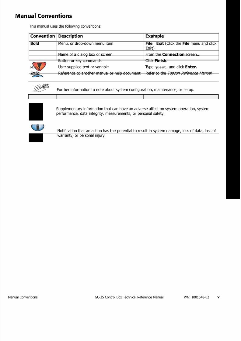
7172019 GC 35 Tecnical Reference Manual
httpslidepdfcomreaderfullgc-35-tecnical-reference-manual 823
Manual Conventions vGC-35 Control Box Technical Reference Manual PN 1001548-02
Manual Conventions
This manual uses the following conventions
Convention Description Example
Bold Menu or drop-down menu item File Exit (Click the File menu and clickExit)
Name of a dialog box or screen From the Connection screen
Button or key commands Click Finish
Mono User supplied text or variable Type guest and click Enter
Italic Reference to another manual or help document Refer to the Topcon Reference Manual
Further information to note about system configuration maintenance or setup
Supplementary information that can have an adverse affect on system operation systemperformance data integrity measurements or personal safety
Notification that an action has the potential to result in system damage loss of data loss ofwarranty or personal injury
7172019 GC 35 Tecnical Reference Manual
httpslidepdfcomreaderfullgc-35-tecnical-reference-manual 923
Introduction 1GC-35 Control Box Technical Reference Manual PN 1001548-02
bull bull bull bull bull bull
Introduction
The Technicians Menu contains additional system menu items not available to the operator (end user) in the GC-35 Control Box Performance Menu
These menu items offer the ability to override default settings of the P-32 system to improve system performancein certain situations These menu items are not however meant to be changed by the operator
The following sections describe the features of the GC-35 control box and explain how to access the TechnicianrsquosMenu select a menu item save the new value and exit the Technicianrsquos Menu
Features
Figure 1 GC-35 Control Box
Access to the Technicianrsquos Menu is intended for and should be limited to Topcon qualified dealerand field service technicians Any changes to the factory default settings without a thoroughunderstanding to their effects on the P-32 system may cause adverse consequences to systemaccuracy and operation
Auto Indicator LED
Auto Button
Survey Button
Elevation Indicator
LED (Green)
Slope Indicator
LED (Yellow)
SlopeElevation
Button
Jog UpDown
Buttons
LCD
Light Sensor
Power OnOff
Button
Grade Adjustment
Knob
Grade Adjustment
Arrows
Menu Selection
Buttons
Grade Indicator
LEDs
USB Port
USB Cap
(Removed)
Jaw Mount
Power Connector
Sonic Tracker or Slope Sensor
Connectors
7172019 GC 35 Tecnical Reference Manual
httpslidepdfcomreaderfullgc-35-tecnical-reference-manual 1023
owering the Control Box OnOff 2GC-35 Control Box Technical Reference Manual PN 1001548-02
Powering the Control Box OnOff
Figure 2 Power OnOff
Control ScreenThe Control Screen displays when you power on the control box It is your interface with the components ofthe P-32 system The Control Screen changes depending on how you have configured the Control Box and theP-32 system
The illustration below shows an example of a Control Box set up to display information from a secondary ControlBox set up for Slope Control
Figure 3 Control Screen
Power OnOff
Button
Startup Screen Shutdown Screen
GC-35
Shutting Down
con1047297g 21
Elevation Set
Point Value
Actual Elevation
Sensor Reading
Slope Set Point Value
PositiveNegative
Slope Indicator Icon
Actual Slope
Sensor Reading
MenuSet
Button Function
Display Area
Elevation Icon
Units (ftincm)
ST-3 SurfaceStringline Mode Icon
Display Slope Box
Auto Icon
Slope Icon
Primary Control Box Display Area
Secondary Control Box
Display Area
Cross Communication
On-Grade Icon
7172019 GC 35 Tecnical Reference Manual
httpslidepdfcomreaderfullgc-35-tecnical-reference-manual 1123
ccessing the Technicianrsquos Menu 3GC-35 Control Box Technical Reference Manual PN 1001548-02
Accessing the Technicianrsquos Menu
1 From the Control Screen press the MenuSet button
2 Rotate the Grade Adjustment Knob to scroll through the menu selections displayed on the screen
3 Select Tech Menu and press and hold the Enter button for three (3) seconds to enter the
Technicianrsquos Menu
Figure 4 Accessing the Technicianrsquos Menu
Press MenuSet Button Turn Grade Adjustment Knob Press and Hold
Enter Button for 3 Seconds
7172019 GC 35 Tecnical Reference Manual
httpslidepdfcomreaderfullgc-35-tecnical-reference-manual 1223
Technicianrsquos Menu 9GC-35 Control Box Technical Reference Manual PN 1001548-02
bull bull bull bull bull bull
Technicianrsquos Menu
This chapter describes the Technicianrsquos Menu items and their default factory settings
Table 1 lists the available menus
Table 1 Technicianrsquos Menu Settings
Menu Item Range Default Factory Setting
Configuration External 0ndash31 Custom External
Averaging 1 ndash 100 50
Valve Type Solenoid ProportionalDanfoss Pulse WidthModulated
Proportional
Valve Drive Sink Source Sink
Dither Amplitude 0ndash15 4
Dither Frequency 0ndash105 42
Frequency 1ndash13Hz
225ndash1950Hz
5Hz
Max Current 067ndash48 Amps 175 Amps
Hour Read only Hours 00
Hours Auto 00
External Auto On Off Invert Off
Auto Power Up (Paver only) On Off On
Esup2 Reset Cancel Reset Cancel
Lock Menu Level 1 - Unlocked
Level 2 - Moderate
Level 3 - Restricted
Level 1 - Unlocked
Elevation Gains Raise 1 ndash 200 Raise 25
Lower 1 ndash 200 Lower 25
Slope Gain 1 ndash 100 25
Valve Offsets Raise 1 ndash 999 Raise 135
Lower 1 ndash 999 Lower 135
Elevation Deadband 1 ndash 30 mm 3 mm
Slope Deadband 0025 ndash 075 0075
Working Window 0ndash500 Off 020 ft
Slope Working Window 01-100 20
Smartlink Slope 0 - 100 Slope 0
Elevation 0 - 100 Elevation 0
7172019 GC 35 Tecnical Reference Manual
httpslidepdfcomreaderfullgc-35-tecnical-reference-manual 1323
onfiguration 10GC-35 Control Box Technical Reference Manual PN 1001548-02
Configuration
This setting selects a valve drive configuration and has up to 32 preprogrammed configurations to select from You may also create a custom configuration
Configuration Value Range External 0-31 Custom
Default External
bull External ndash Upon power up the control box looks for an external configuration resistor between pins Land K of the 11 pin bulkhead connector and defaults to the listed configuration table for valve control
The configuration number displays on the control box LCD when the box is turned onbull Value between 0-31 ndash The control box defaults to the valve control parameters for this number listed inthe configuration chart (see Table 2 on page 10) The configuration number displays on the control boxLCD when the box is turned on
bull Custom ndash Create a custom valve control configuration by setting the Valve Type Current DirectionCurrent Limit Frequency (for PWM modes and Solenoid) Dither Amplitude (except Solenoid mode) andDither Frequency (except Solenoid mode)
Configuration Codes
Table 2 lists available configurations
Table 2 Configuration Codes
ConfigResistor
(ohms)
Drive Type Current Direction Dither Amplitude Dither Freq Freq Hz Current Limit
0 0 Sol Sink None None Adj None
1 77
2 160
3 249
4 341
5 441 Sol Source None None Adj None
6 560 Sol Source None None Adj None
7 670
8 800 Sol Source None None Adj None
9 940 Sol Source None None Adj None10 1100 Sol Sink None None Adj None
11 1260 Sol Source None None Adj
12 1445
14 1890
15 2140 Pro Cur Source 6 42 NA 175A
17 2760 Sol Sink None None Adj None
18 3140 Sol Sink None None Adj None
19 3583 Sol Source None None Adj None
20 4104 Sol Sink None None Adj None
21 4725 Sol Sink None None Adj None
22 5480 Sol
23 6414
26 11310 Sol Source None None Adj None
27 14440
28 19440
29 28670
30 51500 Pro Cur Source 12 42 NA 175A
31 open Pro Cur Sink 6 42 NA 175A
7172019 GC 35 Tecnical Reference Manual
httpslidepdfcomreaderfullgc-35-tecnical-reference-manual 1423
veraging 11GC-35 Control Box Technical Reference Manual PN 1001548-02
Averaging
Averaging changes the amount of dampening or filtering applied to the laser receiver or elevation sensormeasurements Averaging can be thought of as the time period over which a running average of the elevationmeasurement is calculated
Averaging Value Range 1ndash100
Default 50
A lower value averages fewer elevation measurements allowing the system to react more quickly to grade
changes
A larger value averages more elevation measurements making the system less reactive to fluctuations in gradesuch as with laser ldquobeam bouncerdquo on windy days
Valve Type
Valve Type allows you to select the type of valves used on your machine
Valve Type Value Range Solenoid Servo Proportional Danfoss Pulse PWMDefault Proportional
The following sections describe each of these valve types
Proportional Current
Proportional Current provides a current regulated proportional output and is the preferred setting forproportional valves
A percentage of the total current setting is calculated based on the gain setting and given grade correctionProportional Current control applies full machine voltage to the valve coil until the desired current is reachedthen the voltage is turned off When the current drops below the desired value the process is repeated
Proportional Pulse Width Modulated
Proportional Pulse Width Modulated provides a pulse width regulated proportional output
A percentage of the total duty cycle is calculated based on the gain setting and the given grade correction PulseWidth Modulation cycles the output voltage on and off at the desired duty cycle
Solenoid
Solenoid operates the same as PWM mode except set up specifically for the lower frequency solenoid valves
Danfoss
Danfoss provides a proportional voltage output to drive the specific requirements of the Danfoss brand ofproportional valves In this mode switched power (Vsw) and ground connect to the Danfoss valve through thevalve cable and the Raise output pin of the control box controls the reference signal to the valve In a neutral(no grade) correction output the reference signal is held at half of the switched voltage For example if a 12volt system produced 13 volts on the Vsw line 65 volts are held on the reference output for a no correctionsignal
bull For a raise correction signal the control box increases the reference voltage from 65 to a maximum of975 V
Averaging does not affect slope control
7172019 GC 35 Tecnical Reference Manual
httpslidepdfcomreaderfullgc-35-tecnical-reference-manual 1523
alve Drive 12GC-35 Control Box Technical Reference Manual PN 1001548-02
bull For a lower output signal the control box decreases the reference voltage to a minimum of 325 V
Valve Drive
Valve Drive selects the current direction of the valves on the machine
Valve Drive Value Range Sink Source
Select Sink if the valve has a permanent positive connection and needs a switched negative connection (thecontrol box sinks current)
Select Source if the valve has a permanent ground (negative) connection and needs a switched positiveconnection (the control box sources current)
Dither Amplitude
Dither Amplitude allows you to select the amount of dither to apply to the valve
Dither is a continuous low frequency ldquopulserdquo applied to the valve drive signal for proportional valves to keep thevalversquos spool from sticking
Dither Amplitude Value Range 0ndash15
Dither Amplitude is a percentage of full current for the Proportional Current valve type or duty cycle for thePWM valve type Dither does not apply for Solenoid Danfoss or Servo valve types
Dither Frequency
Dither Frequency adjusts the frequency of the dither in cycles per second
Dither Frequency Value Range 0ndash105 Hz
Frequency
Frequency adjusts the number of pulses sent to control valves in one secondFrequency Value Range 1ndash13 Hz 225ndash1950 Hz
The frequency value is adjustable from 1 to 13 Hz for Solenoid valves On Pulse Width Modulated mode valvesthe range is 225 to 1950 Hz
Max Current
Max Current adjusts the maximum valve drive current that the control box outputs when using ProportionalCurrent valve output mode and the over-current trip level for other valve types
Current Limit Value Range 067ndash48 Amps
If a Danfoss valve sees a reference voltage greater than 75 of Vsw or below 25 of Vsw the valvedefaults to an ldquoerrorrdquo state and the valve is held in the neutral position
Frequency does not apply for Proportional Current and Danfoss valve types
Changing the Frequency has an effect on the Offset Check the Offset after changing theFrequency
7172019 GC 35 Tecnical Reference Manual
httpslidepdfcomreaderfullgc-35-tecnical-reference-manual 1623
our 13GC-35 Control Box Technical Reference Manual PN 1001548-02
Hour
Hour displays the amount of hours the control box has been operating and the amount of hours the control boxhas been operating in Automatic
Hour Settings No settings (read only)
External Auto
External Auto disables or enables an external automanual switch
External Auto Settings OnOffInvert
If On is selected the system requires both an external AM switch and activation of the Control Boxrsquos Autobutton to switch the system in and out of Automatic control Activate the external AM switch by connectingpin E of the 11 PIN bulkhead to ground
If you select Invert connecting pin E to ground takes the system out of Automatic control Automatic controlactivates only when pin E is connected to power such as when connecting to an in-motion switch
Auto Power (Paver Only)
The Auto Power setting allows the system to automatically power up to the last used mode
Auto Power Settings OnOff
When the Auto Power setting is On the system powers up in the last mode seen before power down (Auto orManual) For example the paver is in automatic control is shut down and then powered up once more Thepaver is now ready to pave in Auto
When the Auto Power setting is Off the operator must press the Auto button to return to Auto after a powerdown
Esup2 Reset
Esup2 Reset reconfigures the system to factory settings
Esup2 Reset Settings Range CancelReset
To reset all settings in the Performance Menu and the Technician Menu to factory defaults select Reset and press and hold the Enter button for three (3) seconds
To cancel and return to the previous screen select Cancel
Lock Menu
The Lock-Out Setting allows certain Performance Settings in the Performance Menu to be made inaccessibleto the operator (see ldquoPaver Lock Menu Settingsrdquo on page 14)
If the Auto Power setting is On the machine powers up in Auto any time it was shut down in AutoOnly use Auto Power On in asphalt paver applications
Setting Auto Power to On for a machine other than asphalt pavers is not recommended Seriousinjury to operators or bystanders from unexpected machine movement could result
If you select Reset the Control Box reverts your custom Control Box settings back to their factorydefault values
7172019 GC 35 Tecnical Reference Manual
httpslidepdfcomreaderfullgc-35-tecnical-reference-manual 1723
levation Gains (Raise and Lower) 14GC-35 Control Box Technical Reference Manual PN 1001548-02
Lock-Out Value Range Level 1 - Unlocked Level2 - Moderate Level 3 - Restricted
bull Level 1 ndash all Performance Menu items are accessible to the operator
bull Level 2ndash some items no longer appear in the Performance Menu and are only accessible in theTechnicianrsquos Menu
bull Level 3 ndash additional items no longer appear in the Performance Menu and are only accessible in theTechnicianrsquos Menu
Lock Menu Settings
Table 3 lists the settings that can be locked out (made unavailable)
Elevation Gains (Raise and Lower)
Elevation Gains determines the speed at which your Topcon P-32 System allows the tow point cylinders to adjustto a change in elevation For faster hydraulic response increase the gain value For slower hydraulic responsedecrease the gain value
The objective is to set the gain so the screed reacts to the change in grade quickly but without ldquoovershootingrdquothe new elevation
Gain Elevation Value Range 1-200
Table 3 Paver Lock Menu Settings
Performance Menu Item Level 1 - Unlocked Level 2 - Moderate Level 3 - Restricted
1 Elevation Gains Available Available Locked
2 Slope Gain Available Available Locked
3 Valve Offsets Available Available Locked
4 Elevation Deadband Available Locked Locked
5 Slope Deadband Available Locked Locked
6 Averaging Available Locked Locked
7 Machine Type Available Available Available
8 Display Available Available Available
9 Units Available Available Available
10 System Info Available Available Available
11 Sonic Tracker 3 Available Available Available
12 Slope Resolution Available Available Available
13 Slope Cal Block Available Available Locked
14 Tech Menu Available Available Available
Before setting the Elevation Gain make sure the machines hydraulic flow controls valves are adjustedfor proper cylinder speed according to the manufacturers recommendations
7172019 GC 35 Tecnical Reference Manual
httpslidepdfcomreaderfullgc-35-tecnical-reference-manual 1823
lope Gain 15GC-35 Control Box Technical Reference Manual PN 1001548-02
Slope Gain
This setting determines the speed at which your Topcon P-32 System allows the tow point cylinders to adjustto a change in slope For faster hydraulic response increase the gain value For slower hydraulic responsedecrease the gain value
The objective is to set the gain so the screed reacts to the change in grade quickly but without ldquoovershootingrdquoOn-Grade Slope Gain should not be set at a higher value than the Elevation Gain on the other side of the paver
Gain Elevation Value Range 1-100
Valve Offsets (Raise and Lower)
Valve Offsets is the minimum amount of electrical signals sent to the valve which causes the hydraulic cylinderto move If the valve offset is too small the sensor will not reach On-Grade Likewise if the valve offset valueis too large the sensor will move too much and overshoot On-Grade
Run the Paver until the hydraulic oil is at normal operating temperature before setting the valve offsets Oncethey are set you should not need to readjust the valve offsets unless the Control Box is moved to a new paveror the hydraulic performance changes
Valve Offset Value Range (Raise and Lower) 1 - 999
Elevation Deadband
Elevation Deadband is the area of the Working Window that is On-Grade While the reference is within that areathe paverrsquos valves are idle (closed) Therefore the wider the Elevation Deadband (On-Grade area) the more areference can move up or down without a correction being initiated Once the signal from the reference is outof the deadband your control box drives the hydraulics to place the reference back in the center of thedeadband
Deadband Elevation Value Range 1ndash30 mm
Before setting the Slope Gain ensure the machines hydraulic flow control valves are adjusted forproper cylinder speed according to the manufacturers recommendations
Do not set slope gain at a higher value than the elevation gain on the other side of the paver A highervalue may cause the slope to be over reactive
Set the Valve Offsets before adjusting elevation and slope gains and averaging
The offset value on one side of the paver may differ from the offset value on the other side of thepaver You must verify the offset values before swapping boxes Use the ldquoLeftrdquo and ldquoRightrdquo labelsprovided
Never attempt to use Valve Offsets to compensate for a slower raise or lower speed of your hydraulicvalves as it causes undershooting or overshooting in Slope Mode and can adversely affect the qualityof the mat
Select the amount of Elevation Deadband carefully Too small of an Elevation Deadband causes thetow point cylinder to constantly hunt up and down while the sensor tries to find On-Grade Too largeof an Elevation Deadband does not allow the sensor to send grade corrections to the values causingunwanted variations in mat thickness
7172019 GC 35 Tecnical Reference Manual
httpslidepdfcomreaderfullgc-35-tecnical-reference-manual 1923
lope Deadband 16GC-35 Control Box Technical Reference Manual PN 1001548-02
Slope Deadband
Slope Deadband defines the size of the on-grade area where no valve corrections are made
Deadband Slope Value Range 0025ndash075
The wider the Slope Deadband the greater the slope can vary without initiating a correction
For example if the operator is grading at a 20 slope and the Slope Deadband is set at 10 the system
reads on-grade anywhere from 195 slope to 205 slope The lower the percentage the tighter the SlopeDeadband
Once the slope signal is out of the Slope Deadband System Five drives the hydraulics back within the SlopeDeadband
Working Window Adjustment
Working Window Adjustment adjusts the working window of the sonic tracker (Figure 5)
Working Window Settings 0ndash500 Off
Default 020
The default setting is 020 which gives 020 ft (61 mm) above and below on-grade Setting the value to Offcompletely disables the working window and allows any target to be seen
7172019 GC 35 Tecnical Reference Manual
httpslidepdfcomreaderfullgc-35-tecnical-reference-manual 2023
lope Working Window 17GC-35 Control Box Technical Reference Manual PN 1001548-02
Figure 5 Sonic Tracker Working Window
Slope Working Window
Slope Working Window adjusts the working window of the Slope Sensor (Figure 6)
Slope Working Window Value Range 01 - 100 Off
Default 20
The default setting is 20 which gives 20 slope above and below ongrade Setting the value to Off completelydisables the working window
Out of Range
Ongrade
Flashing UpDown Arrow
Solid UpDown Arrow
20rsquo
20rsquo
20rsquo
20rsquo
Working
Window
(Adjustable)
ST-3 Sonic Tracker II
When using the Sonic Tracker II to follow a stringline curb or other elevated reference there is adanger of making an unwanted cut if the Trackerrsquos sonic cone moves away from the target This canoccur if the working window is either off or set as high as the distance between the reference and theground Setting the working window to the default value of 20 (020ft) prevents the automatic controlfrom making such a reaction due to a loss of the target
7172019 GC 35 Tecnical Reference Manual
httpslidepdfcomreaderfullgc-35-tecnical-reference-manual 2123
martlink (Elevation and Slope) 18GC-35 Control Box Technical Reference Manual PN 1001548-02
Figure 6 Slope Working Window
Smartlink (Elevation and Slope)
Smartlink allows the Control Box to send a percentage of the slopeelevation correction on one side of themachine to the Control Box on the other side of the machine preemptively raising or lowering that hydrauliccylinder to keep the machine at the correct grade Smartlink decreases the lag in correction that can occur onone side of the machine as the second Control Box begins moving the valve without having to wait for thesensor on the other side of the machine to detect and correct for a change in elevationslope
Smartlink Value Range 0 - 100
Default 0
Out of Range
Working Window (Adjustable)
Ongrade
20
20
Ongrade
20
20
7172019 GC 35 Tecnical Reference Manual
httpslidepdfcomreaderfullgc-35-tecnical-reference-manual 2223
Warranty 19GC-35 Control Box Technical Reference Manual PN 1001548-02
bull bull bull bull bull bull
Warranty
Topcon laser and electronic positioning equipment are guaranteed against defective material and workmanshipunder normal use and application consistent with this Manual The equipment is guaranteed for the period indicatedon the warranty card accompanying the product starting from the date that the product is sold to the originalpurchaser by Topconrsquos Authorized Dealers1
During the warranty period Topcon will at its option repair or replace this product at no additional charge Repairparts and replacement products will be furnished on an exchange basis and will be either reconditioned or new Thislimited warranty does not include service to repair damage to the product resulting from an accident disastermisuses abuse or modification of the product
Warranty service may be obtained from an authorized Topcon warranty service dealer If this product is deliveredby mail purchaser agrees to insure the product or assume the risk of loss or damage in transit to prepay shippingcharges to the warranty service location and to use the original shipping container or equivalent A letter shouldaccompany the package furnishing a description of the problem andor defect
The purchaserrsquos sole remedy shall be replacement as provided above In no event shall Topcon be liable for anydamages or other claim including any claim for lost profits lost savings or other incidental or consequential damagesarising out of the use of or inability to use the product
1 The warranty against defects in a Topcon battery charger or cable is 90 days
7172019 GC 35 Tecnical Reference Manual
httpslidepdfcomreaderfullgc-35-tecnical-reference-manual 2323
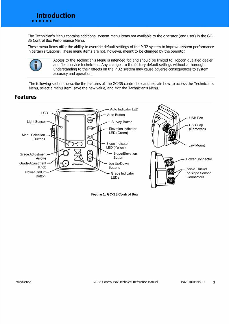
7172019 GC 35 Tecnical Reference Manual
httpslidepdfcomreaderfullgc-35-tecnical-reference-manual 923
Introduction 1GC-35 Control Box Technical Reference Manual PN 1001548-02
bull bull bull bull bull bull
Introduction
The Technicians Menu contains additional system menu items not available to the operator (end user) in the GC-35 Control Box Performance Menu
These menu items offer the ability to override default settings of the P-32 system to improve system performancein certain situations These menu items are not however meant to be changed by the operator
The following sections describe the features of the GC-35 control box and explain how to access the TechnicianrsquosMenu select a menu item save the new value and exit the Technicianrsquos Menu
Features
Figure 1 GC-35 Control Box
Access to the Technicianrsquos Menu is intended for and should be limited to Topcon qualified dealerand field service technicians Any changes to the factory default settings without a thoroughunderstanding to their effects on the P-32 system may cause adverse consequences to systemaccuracy and operation
Auto Indicator LED
Auto Button
Survey Button
Elevation Indicator
LED (Green)
Slope Indicator
LED (Yellow)
SlopeElevation
Button
Jog UpDown
Buttons
LCD
Light Sensor
Power OnOff
Button
Grade Adjustment
Knob
Grade Adjustment
Arrows
Menu Selection
Buttons
Grade Indicator
LEDs
USB Port
USB Cap
(Removed)
Jaw Mount
Power Connector
Sonic Tracker or Slope Sensor
Connectors
7172019 GC 35 Tecnical Reference Manual
httpslidepdfcomreaderfullgc-35-tecnical-reference-manual 1023
owering the Control Box OnOff 2GC-35 Control Box Technical Reference Manual PN 1001548-02
Powering the Control Box OnOff
Figure 2 Power OnOff
Control ScreenThe Control Screen displays when you power on the control box It is your interface with the components ofthe P-32 system The Control Screen changes depending on how you have configured the Control Box and theP-32 system
The illustration below shows an example of a Control Box set up to display information from a secondary ControlBox set up for Slope Control
Figure 3 Control Screen
Power OnOff
Button
Startup Screen Shutdown Screen
GC-35
Shutting Down
con1047297g 21
Elevation Set
Point Value
Actual Elevation
Sensor Reading
Slope Set Point Value
PositiveNegative
Slope Indicator Icon
Actual Slope
Sensor Reading
MenuSet
Button Function
Display Area
Elevation Icon
Units (ftincm)
ST-3 SurfaceStringline Mode Icon
Display Slope Box
Auto Icon
Slope Icon
Primary Control Box Display Area
Secondary Control Box
Display Area
Cross Communication
On-Grade Icon
7172019 GC 35 Tecnical Reference Manual
httpslidepdfcomreaderfullgc-35-tecnical-reference-manual 1123
ccessing the Technicianrsquos Menu 3GC-35 Control Box Technical Reference Manual PN 1001548-02
Accessing the Technicianrsquos Menu
1 From the Control Screen press the MenuSet button
2 Rotate the Grade Adjustment Knob to scroll through the menu selections displayed on the screen
3 Select Tech Menu and press and hold the Enter button for three (3) seconds to enter the
Technicianrsquos Menu
Figure 4 Accessing the Technicianrsquos Menu
Press MenuSet Button Turn Grade Adjustment Knob Press and Hold
Enter Button for 3 Seconds
7172019 GC 35 Tecnical Reference Manual
httpslidepdfcomreaderfullgc-35-tecnical-reference-manual 1223
Technicianrsquos Menu 9GC-35 Control Box Technical Reference Manual PN 1001548-02
bull bull bull bull bull bull
Technicianrsquos Menu
This chapter describes the Technicianrsquos Menu items and their default factory settings
Table 1 lists the available menus
Table 1 Technicianrsquos Menu Settings
Menu Item Range Default Factory Setting
Configuration External 0ndash31 Custom External
Averaging 1 ndash 100 50
Valve Type Solenoid ProportionalDanfoss Pulse WidthModulated
Proportional
Valve Drive Sink Source Sink
Dither Amplitude 0ndash15 4
Dither Frequency 0ndash105 42
Frequency 1ndash13Hz
225ndash1950Hz
5Hz
Max Current 067ndash48 Amps 175 Amps
Hour Read only Hours 00
Hours Auto 00
External Auto On Off Invert Off
Auto Power Up (Paver only) On Off On
Esup2 Reset Cancel Reset Cancel
Lock Menu Level 1 - Unlocked
Level 2 - Moderate
Level 3 - Restricted
Level 1 - Unlocked
Elevation Gains Raise 1 ndash 200 Raise 25
Lower 1 ndash 200 Lower 25
Slope Gain 1 ndash 100 25
Valve Offsets Raise 1 ndash 999 Raise 135
Lower 1 ndash 999 Lower 135
Elevation Deadband 1 ndash 30 mm 3 mm
Slope Deadband 0025 ndash 075 0075
Working Window 0ndash500 Off 020 ft
Slope Working Window 01-100 20
Smartlink Slope 0 - 100 Slope 0
Elevation 0 - 100 Elevation 0
7172019 GC 35 Tecnical Reference Manual
httpslidepdfcomreaderfullgc-35-tecnical-reference-manual 1323
onfiguration 10GC-35 Control Box Technical Reference Manual PN 1001548-02
Configuration
This setting selects a valve drive configuration and has up to 32 preprogrammed configurations to select from You may also create a custom configuration
Configuration Value Range External 0-31 Custom
Default External
bull External ndash Upon power up the control box looks for an external configuration resistor between pins Land K of the 11 pin bulkhead connector and defaults to the listed configuration table for valve control
The configuration number displays on the control box LCD when the box is turned onbull Value between 0-31 ndash The control box defaults to the valve control parameters for this number listed inthe configuration chart (see Table 2 on page 10) The configuration number displays on the control boxLCD when the box is turned on
bull Custom ndash Create a custom valve control configuration by setting the Valve Type Current DirectionCurrent Limit Frequency (for PWM modes and Solenoid) Dither Amplitude (except Solenoid mode) andDither Frequency (except Solenoid mode)
Configuration Codes
Table 2 lists available configurations
Table 2 Configuration Codes
ConfigResistor
(ohms)
Drive Type Current Direction Dither Amplitude Dither Freq Freq Hz Current Limit
0 0 Sol Sink None None Adj None
1 77
2 160
3 249
4 341
5 441 Sol Source None None Adj None
6 560 Sol Source None None Adj None
7 670
8 800 Sol Source None None Adj None
9 940 Sol Source None None Adj None10 1100 Sol Sink None None Adj None
11 1260 Sol Source None None Adj
12 1445
14 1890
15 2140 Pro Cur Source 6 42 NA 175A
17 2760 Sol Sink None None Adj None
18 3140 Sol Sink None None Adj None
19 3583 Sol Source None None Adj None
20 4104 Sol Sink None None Adj None
21 4725 Sol Sink None None Adj None
22 5480 Sol
23 6414
26 11310 Sol Source None None Adj None
27 14440
28 19440
29 28670
30 51500 Pro Cur Source 12 42 NA 175A
31 open Pro Cur Sink 6 42 NA 175A
7172019 GC 35 Tecnical Reference Manual
httpslidepdfcomreaderfullgc-35-tecnical-reference-manual 1423
veraging 11GC-35 Control Box Technical Reference Manual PN 1001548-02
Averaging
Averaging changes the amount of dampening or filtering applied to the laser receiver or elevation sensormeasurements Averaging can be thought of as the time period over which a running average of the elevationmeasurement is calculated
Averaging Value Range 1ndash100
Default 50
A lower value averages fewer elevation measurements allowing the system to react more quickly to grade
changes
A larger value averages more elevation measurements making the system less reactive to fluctuations in gradesuch as with laser ldquobeam bouncerdquo on windy days
Valve Type
Valve Type allows you to select the type of valves used on your machine
Valve Type Value Range Solenoid Servo Proportional Danfoss Pulse PWMDefault Proportional
The following sections describe each of these valve types
Proportional Current
Proportional Current provides a current regulated proportional output and is the preferred setting forproportional valves
A percentage of the total current setting is calculated based on the gain setting and given grade correctionProportional Current control applies full machine voltage to the valve coil until the desired current is reachedthen the voltage is turned off When the current drops below the desired value the process is repeated
Proportional Pulse Width Modulated
Proportional Pulse Width Modulated provides a pulse width regulated proportional output
A percentage of the total duty cycle is calculated based on the gain setting and the given grade correction PulseWidth Modulation cycles the output voltage on and off at the desired duty cycle
Solenoid
Solenoid operates the same as PWM mode except set up specifically for the lower frequency solenoid valves
Danfoss
Danfoss provides a proportional voltage output to drive the specific requirements of the Danfoss brand ofproportional valves In this mode switched power (Vsw) and ground connect to the Danfoss valve through thevalve cable and the Raise output pin of the control box controls the reference signal to the valve In a neutral(no grade) correction output the reference signal is held at half of the switched voltage For example if a 12volt system produced 13 volts on the Vsw line 65 volts are held on the reference output for a no correctionsignal
bull For a raise correction signal the control box increases the reference voltage from 65 to a maximum of975 V
Averaging does not affect slope control
7172019 GC 35 Tecnical Reference Manual
httpslidepdfcomreaderfullgc-35-tecnical-reference-manual 1523
alve Drive 12GC-35 Control Box Technical Reference Manual PN 1001548-02
bull For a lower output signal the control box decreases the reference voltage to a minimum of 325 V
Valve Drive
Valve Drive selects the current direction of the valves on the machine
Valve Drive Value Range Sink Source
Select Sink if the valve has a permanent positive connection and needs a switched negative connection (thecontrol box sinks current)
Select Source if the valve has a permanent ground (negative) connection and needs a switched positiveconnection (the control box sources current)
Dither Amplitude
Dither Amplitude allows you to select the amount of dither to apply to the valve
Dither is a continuous low frequency ldquopulserdquo applied to the valve drive signal for proportional valves to keep thevalversquos spool from sticking
Dither Amplitude Value Range 0ndash15
Dither Amplitude is a percentage of full current for the Proportional Current valve type or duty cycle for thePWM valve type Dither does not apply for Solenoid Danfoss or Servo valve types
Dither Frequency
Dither Frequency adjusts the frequency of the dither in cycles per second
Dither Frequency Value Range 0ndash105 Hz
Frequency
Frequency adjusts the number of pulses sent to control valves in one secondFrequency Value Range 1ndash13 Hz 225ndash1950 Hz
The frequency value is adjustable from 1 to 13 Hz for Solenoid valves On Pulse Width Modulated mode valvesthe range is 225 to 1950 Hz
Max Current
Max Current adjusts the maximum valve drive current that the control box outputs when using ProportionalCurrent valve output mode and the over-current trip level for other valve types
Current Limit Value Range 067ndash48 Amps
If a Danfoss valve sees a reference voltage greater than 75 of Vsw or below 25 of Vsw the valvedefaults to an ldquoerrorrdquo state and the valve is held in the neutral position
Frequency does not apply for Proportional Current and Danfoss valve types
Changing the Frequency has an effect on the Offset Check the Offset after changing theFrequency
7172019 GC 35 Tecnical Reference Manual
httpslidepdfcomreaderfullgc-35-tecnical-reference-manual 1623
our 13GC-35 Control Box Technical Reference Manual PN 1001548-02
Hour
Hour displays the amount of hours the control box has been operating and the amount of hours the control boxhas been operating in Automatic
Hour Settings No settings (read only)
External Auto
External Auto disables or enables an external automanual switch
External Auto Settings OnOffInvert
If On is selected the system requires both an external AM switch and activation of the Control Boxrsquos Autobutton to switch the system in and out of Automatic control Activate the external AM switch by connectingpin E of the 11 PIN bulkhead to ground
If you select Invert connecting pin E to ground takes the system out of Automatic control Automatic controlactivates only when pin E is connected to power such as when connecting to an in-motion switch
Auto Power (Paver Only)
The Auto Power setting allows the system to automatically power up to the last used mode
Auto Power Settings OnOff
When the Auto Power setting is On the system powers up in the last mode seen before power down (Auto orManual) For example the paver is in automatic control is shut down and then powered up once more Thepaver is now ready to pave in Auto
When the Auto Power setting is Off the operator must press the Auto button to return to Auto after a powerdown
Esup2 Reset
Esup2 Reset reconfigures the system to factory settings
Esup2 Reset Settings Range CancelReset
To reset all settings in the Performance Menu and the Technician Menu to factory defaults select Reset and press and hold the Enter button for three (3) seconds
To cancel and return to the previous screen select Cancel
Lock Menu
The Lock-Out Setting allows certain Performance Settings in the Performance Menu to be made inaccessibleto the operator (see ldquoPaver Lock Menu Settingsrdquo on page 14)
If the Auto Power setting is On the machine powers up in Auto any time it was shut down in AutoOnly use Auto Power On in asphalt paver applications
Setting Auto Power to On for a machine other than asphalt pavers is not recommended Seriousinjury to operators or bystanders from unexpected machine movement could result
If you select Reset the Control Box reverts your custom Control Box settings back to their factorydefault values
7172019 GC 35 Tecnical Reference Manual
httpslidepdfcomreaderfullgc-35-tecnical-reference-manual 1723
levation Gains (Raise and Lower) 14GC-35 Control Box Technical Reference Manual PN 1001548-02
Lock-Out Value Range Level 1 - Unlocked Level2 - Moderate Level 3 - Restricted
bull Level 1 ndash all Performance Menu items are accessible to the operator
bull Level 2ndash some items no longer appear in the Performance Menu and are only accessible in theTechnicianrsquos Menu
bull Level 3 ndash additional items no longer appear in the Performance Menu and are only accessible in theTechnicianrsquos Menu
Lock Menu Settings
Table 3 lists the settings that can be locked out (made unavailable)
Elevation Gains (Raise and Lower)
Elevation Gains determines the speed at which your Topcon P-32 System allows the tow point cylinders to adjustto a change in elevation For faster hydraulic response increase the gain value For slower hydraulic responsedecrease the gain value
The objective is to set the gain so the screed reacts to the change in grade quickly but without ldquoovershootingrdquothe new elevation
Gain Elevation Value Range 1-200
Table 3 Paver Lock Menu Settings
Performance Menu Item Level 1 - Unlocked Level 2 - Moderate Level 3 - Restricted
1 Elevation Gains Available Available Locked
2 Slope Gain Available Available Locked
3 Valve Offsets Available Available Locked
4 Elevation Deadband Available Locked Locked
5 Slope Deadband Available Locked Locked
6 Averaging Available Locked Locked
7 Machine Type Available Available Available
8 Display Available Available Available
9 Units Available Available Available
10 System Info Available Available Available
11 Sonic Tracker 3 Available Available Available
12 Slope Resolution Available Available Available
13 Slope Cal Block Available Available Locked
14 Tech Menu Available Available Available
Before setting the Elevation Gain make sure the machines hydraulic flow controls valves are adjustedfor proper cylinder speed according to the manufacturers recommendations
7172019 GC 35 Tecnical Reference Manual
httpslidepdfcomreaderfullgc-35-tecnical-reference-manual 1823
lope Gain 15GC-35 Control Box Technical Reference Manual PN 1001548-02
Slope Gain
This setting determines the speed at which your Topcon P-32 System allows the tow point cylinders to adjustto a change in slope For faster hydraulic response increase the gain value For slower hydraulic responsedecrease the gain value
The objective is to set the gain so the screed reacts to the change in grade quickly but without ldquoovershootingrdquoOn-Grade Slope Gain should not be set at a higher value than the Elevation Gain on the other side of the paver
Gain Elevation Value Range 1-100
Valve Offsets (Raise and Lower)
Valve Offsets is the minimum amount of electrical signals sent to the valve which causes the hydraulic cylinderto move If the valve offset is too small the sensor will not reach On-Grade Likewise if the valve offset valueis too large the sensor will move too much and overshoot On-Grade
Run the Paver until the hydraulic oil is at normal operating temperature before setting the valve offsets Oncethey are set you should not need to readjust the valve offsets unless the Control Box is moved to a new paveror the hydraulic performance changes
Valve Offset Value Range (Raise and Lower) 1 - 999
Elevation Deadband
Elevation Deadband is the area of the Working Window that is On-Grade While the reference is within that areathe paverrsquos valves are idle (closed) Therefore the wider the Elevation Deadband (On-Grade area) the more areference can move up or down without a correction being initiated Once the signal from the reference is outof the deadband your control box drives the hydraulics to place the reference back in the center of thedeadband
Deadband Elevation Value Range 1ndash30 mm
Before setting the Slope Gain ensure the machines hydraulic flow control valves are adjusted forproper cylinder speed according to the manufacturers recommendations
Do not set slope gain at a higher value than the elevation gain on the other side of the paver A highervalue may cause the slope to be over reactive
Set the Valve Offsets before adjusting elevation and slope gains and averaging
The offset value on one side of the paver may differ from the offset value on the other side of thepaver You must verify the offset values before swapping boxes Use the ldquoLeftrdquo and ldquoRightrdquo labelsprovided
Never attempt to use Valve Offsets to compensate for a slower raise or lower speed of your hydraulicvalves as it causes undershooting or overshooting in Slope Mode and can adversely affect the qualityof the mat
Select the amount of Elevation Deadband carefully Too small of an Elevation Deadband causes thetow point cylinder to constantly hunt up and down while the sensor tries to find On-Grade Too largeof an Elevation Deadband does not allow the sensor to send grade corrections to the values causingunwanted variations in mat thickness
7172019 GC 35 Tecnical Reference Manual
httpslidepdfcomreaderfullgc-35-tecnical-reference-manual 1923
lope Deadband 16GC-35 Control Box Technical Reference Manual PN 1001548-02
Slope Deadband
Slope Deadband defines the size of the on-grade area where no valve corrections are made
Deadband Slope Value Range 0025ndash075
The wider the Slope Deadband the greater the slope can vary without initiating a correction
For example if the operator is grading at a 20 slope and the Slope Deadband is set at 10 the system
reads on-grade anywhere from 195 slope to 205 slope The lower the percentage the tighter the SlopeDeadband
Once the slope signal is out of the Slope Deadband System Five drives the hydraulics back within the SlopeDeadband
Working Window Adjustment
Working Window Adjustment adjusts the working window of the sonic tracker (Figure 5)
Working Window Settings 0ndash500 Off
Default 020
The default setting is 020 which gives 020 ft (61 mm) above and below on-grade Setting the value to Offcompletely disables the working window and allows any target to be seen
7172019 GC 35 Tecnical Reference Manual
httpslidepdfcomreaderfullgc-35-tecnical-reference-manual 2023
lope Working Window 17GC-35 Control Box Technical Reference Manual PN 1001548-02
Figure 5 Sonic Tracker Working Window
Slope Working Window
Slope Working Window adjusts the working window of the Slope Sensor (Figure 6)
Slope Working Window Value Range 01 - 100 Off
Default 20
The default setting is 20 which gives 20 slope above and below ongrade Setting the value to Off completelydisables the working window
Out of Range
Ongrade
Flashing UpDown Arrow
Solid UpDown Arrow
20rsquo
20rsquo
20rsquo
20rsquo
Working
Window
(Adjustable)
ST-3 Sonic Tracker II
When using the Sonic Tracker II to follow a stringline curb or other elevated reference there is adanger of making an unwanted cut if the Trackerrsquos sonic cone moves away from the target This canoccur if the working window is either off or set as high as the distance between the reference and theground Setting the working window to the default value of 20 (020ft) prevents the automatic controlfrom making such a reaction due to a loss of the target
7172019 GC 35 Tecnical Reference Manual
httpslidepdfcomreaderfullgc-35-tecnical-reference-manual 2123
martlink (Elevation and Slope) 18GC-35 Control Box Technical Reference Manual PN 1001548-02
Figure 6 Slope Working Window
Smartlink (Elevation and Slope)
Smartlink allows the Control Box to send a percentage of the slopeelevation correction on one side of themachine to the Control Box on the other side of the machine preemptively raising or lowering that hydrauliccylinder to keep the machine at the correct grade Smartlink decreases the lag in correction that can occur onone side of the machine as the second Control Box begins moving the valve without having to wait for thesensor on the other side of the machine to detect and correct for a change in elevationslope
Smartlink Value Range 0 - 100
Default 0
Out of Range
Working Window (Adjustable)
Ongrade
20
20
Ongrade
20
20
7172019 GC 35 Tecnical Reference Manual
httpslidepdfcomreaderfullgc-35-tecnical-reference-manual 2223
Warranty 19GC-35 Control Box Technical Reference Manual PN 1001548-02
bull bull bull bull bull bull
Warranty
Topcon laser and electronic positioning equipment are guaranteed against defective material and workmanshipunder normal use and application consistent with this Manual The equipment is guaranteed for the period indicatedon the warranty card accompanying the product starting from the date that the product is sold to the originalpurchaser by Topconrsquos Authorized Dealers1
During the warranty period Topcon will at its option repair or replace this product at no additional charge Repairparts and replacement products will be furnished on an exchange basis and will be either reconditioned or new Thislimited warranty does not include service to repair damage to the product resulting from an accident disastermisuses abuse or modification of the product
Warranty service may be obtained from an authorized Topcon warranty service dealer If this product is deliveredby mail purchaser agrees to insure the product or assume the risk of loss or damage in transit to prepay shippingcharges to the warranty service location and to use the original shipping container or equivalent A letter shouldaccompany the package furnishing a description of the problem andor defect
The purchaserrsquos sole remedy shall be replacement as provided above In no event shall Topcon be liable for anydamages or other claim including any claim for lost profits lost savings or other incidental or consequential damagesarising out of the use of or inability to use the product
1 The warranty against defects in a Topcon battery charger or cable is 90 days
7172019 GC 35 Tecnical Reference Manual
httpslidepdfcomreaderfullgc-35-tecnical-reference-manual 2323
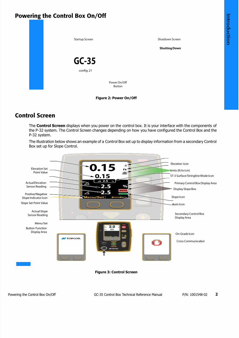
7172019 GC 35 Tecnical Reference Manual
httpslidepdfcomreaderfullgc-35-tecnical-reference-manual 1023
owering the Control Box OnOff 2GC-35 Control Box Technical Reference Manual PN 1001548-02
Powering the Control Box OnOff
Figure 2 Power OnOff
Control ScreenThe Control Screen displays when you power on the control box It is your interface with the components ofthe P-32 system The Control Screen changes depending on how you have configured the Control Box and theP-32 system
The illustration below shows an example of a Control Box set up to display information from a secondary ControlBox set up for Slope Control
Figure 3 Control Screen
Power OnOff
Button
Startup Screen Shutdown Screen
GC-35
Shutting Down
con1047297g 21
Elevation Set
Point Value
Actual Elevation
Sensor Reading
Slope Set Point Value
PositiveNegative
Slope Indicator Icon
Actual Slope
Sensor Reading
MenuSet
Button Function
Display Area
Elevation Icon
Units (ftincm)
ST-3 SurfaceStringline Mode Icon
Display Slope Box
Auto Icon
Slope Icon
Primary Control Box Display Area
Secondary Control Box
Display Area
Cross Communication
On-Grade Icon
7172019 GC 35 Tecnical Reference Manual
httpslidepdfcomreaderfullgc-35-tecnical-reference-manual 1123
ccessing the Technicianrsquos Menu 3GC-35 Control Box Technical Reference Manual PN 1001548-02
Accessing the Technicianrsquos Menu
1 From the Control Screen press the MenuSet button
2 Rotate the Grade Adjustment Knob to scroll through the menu selections displayed on the screen
3 Select Tech Menu and press and hold the Enter button for three (3) seconds to enter the
Technicianrsquos Menu
Figure 4 Accessing the Technicianrsquos Menu
Press MenuSet Button Turn Grade Adjustment Knob Press and Hold
Enter Button for 3 Seconds
7172019 GC 35 Tecnical Reference Manual
httpslidepdfcomreaderfullgc-35-tecnical-reference-manual 1223
Technicianrsquos Menu 9GC-35 Control Box Technical Reference Manual PN 1001548-02
bull bull bull bull bull bull
Technicianrsquos Menu
This chapter describes the Technicianrsquos Menu items and their default factory settings
Table 1 lists the available menus
Table 1 Technicianrsquos Menu Settings
Menu Item Range Default Factory Setting
Configuration External 0ndash31 Custom External
Averaging 1 ndash 100 50
Valve Type Solenoid ProportionalDanfoss Pulse WidthModulated
Proportional
Valve Drive Sink Source Sink
Dither Amplitude 0ndash15 4
Dither Frequency 0ndash105 42
Frequency 1ndash13Hz
225ndash1950Hz
5Hz
Max Current 067ndash48 Amps 175 Amps
Hour Read only Hours 00
Hours Auto 00
External Auto On Off Invert Off
Auto Power Up (Paver only) On Off On
Esup2 Reset Cancel Reset Cancel
Lock Menu Level 1 - Unlocked
Level 2 - Moderate
Level 3 - Restricted
Level 1 - Unlocked
Elevation Gains Raise 1 ndash 200 Raise 25
Lower 1 ndash 200 Lower 25
Slope Gain 1 ndash 100 25
Valve Offsets Raise 1 ndash 999 Raise 135
Lower 1 ndash 999 Lower 135
Elevation Deadband 1 ndash 30 mm 3 mm
Slope Deadband 0025 ndash 075 0075
Working Window 0ndash500 Off 020 ft
Slope Working Window 01-100 20
Smartlink Slope 0 - 100 Slope 0
Elevation 0 - 100 Elevation 0
7172019 GC 35 Tecnical Reference Manual
httpslidepdfcomreaderfullgc-35-tecnical-reference-manual 1323
onfiguration 10GC-35 Control Box Technical Reference Manual PN 1001548-02
Configuration
This setting selects a valve drive configuration and has up to 32 preprogrammed configurations to select from You may also create a custom configuration
Configuration Value Range External 0-31 Custom
Default External
bull External ndash Upon power up the control box looks for an external configuration resistor between pins Land K of the 11 pin bulkhead connector and defaults to the listed configuration table for valve control
The configuration number displays on the control box LCD when the box is turned onbull Value between 0-31 ndash The control box defaults to the valve control parameters for this number listed inthe configuration chart (see Table 2 on page 10) The configuration number displays on the control boxLCD when the box is turned on
bull Custom ndash Create a custom valve control configuration by setting the Valve Type Current DirectionCurrent Limit Frequency (for PWM modes and Solenoid) Dither Amplitude (except Solenoid mode) andDither Frequency (except Solenoid mode)
Configuration Codes
Table 2 lists available configurations
Table 2 Configuration Codes
ConfigResistor
(ohms)
Drive Type Current Direction Dither Amplitude Dither Freq Freq Hz Current Limit
0 0 Sol Sink None None Adj None
1 77
2 160
3 249
4 341
5 441 Sol Source None None Adj None
6 560 Sol Source None None Adj None
7 670
8 800 Sol Source None None Adj None
9 940 Sol Source None None Adj None10 1100 Sol Sink None None Adj None
11 1260 Sol Source None None Adj
12 1445
14 1890
15 2140 Pro Cur Source 6 42 NA 175A
17 2760 Sol Sink None None Adj None
18 3140 Sol Sink None None Adj None
19 3583 Sol Source None None Adj None
20 4104 Sol Sink None None Adj None
21 4725 Sol Sink None None Adj None
22 5480 Sol
23 6414
26 11310 Sol Source None None Adj None
27 14440
28 19440
29 28670
30 51500 Pro Cur Source 12 42 NA 175A
31 open Pro Cur Sink 6 42 NA 175A
7172019 GC 35 Tecnical Reference Manual
httpslidepdfcomreaderfullgc-35-tecnical-reference-manual 1423
veraging 11GC-35 Control Box Technical Reference Manual PN 1001548-02
Averaging
Averaging changes the amount of dampening or filtering applied to the laser receiver or elevation sensormeasurements Averaging can be thought of as the time period over which a running average of the elevationmeasurement is calculated
Averaging Value Range 1ndash100
Default 50
A lower value averages fewer elevation measurements allowing the system to react more quickly to grade
changes
A larger value averages more elevation measurements making the system less reactive to fluctuations in gradesuch as with laser ldquobeam bouncerdquo on windy days
Valve Type
Valve Type allows you to select the type of valves used on your machine
Valve Type Value Range Solenoid Servo Proportional Danfoss Pulse PWMDefault Proportional
The following sections describe each of these valve types
Proportional Current
Proportional Current provides a current regulated proportional output and is the preferred setting forproportional valves
A percentage of the total current setting is calculated based on the gain setting and given grade correctionProportional Current control applies full machine voltage to the valve coil until the desired current is reachedthen the voltage is turned off When the current drops below the desired value the process is repeated
Proportional Pulse Width Modulated
Proportional Pulse Width Modulated provides a pulse width regulated proportional output
A percentage of the total duty cycle is calculated based on the gain setting and the given grade correction PulseWidth Modulation cycles the output voltage on and off at the desired duty cycle
Solenoid
Solenoid operates the same as PWM mode except set up specifically for the lower frequency solenoid valves
Danfoss
Danfoss provides a proportional voltage output to drive the specific requirements of the Danfoss brand ofproportional valves In this mode switched power (Vsw) and ground connect to the Danfoss valve through thevalve cable and the Raise output pin of the control box controls the reference signal to the valve In a neutral(no grade) correction output the reference signal is held at half of the switched voltage For example if a 12volt system produced 13 volts on the Vsw line 65 volts are held on the reference output for a no correctionsignal
bull For a raise correction signal the control box increases the reference voltage from 65 to a maximum of975 V
Averaging does not affect slope control
7172019 GC 35 Tecnical Reference Manual
httpslidepdfcomreaderfullgc-35-tecnical-reference-manual 1523
alve Drive 12GC-35 Control Box Technical Reference Manual PN 1001548-02
bull For a lower output signal the control box decreases the reference voltage to a minimum of 325 V
Valve Drive
Valve Drive selects the current direction of the valves on the machine
Valve Drive Value Range Sink Source
Select Sink if the valve has a permanent positive connection and needs a switched negative connection (thecontrol box sinks current)
Select Source if the valve has a permanent ground (negative) connection and needs a switched positiveconnection (the control box sources current)
Dither Amplitude
Dither Amplitude allows you to select the amount of dither to apply to the valve
Dither is a continuous low frequency ldquopulserdquo applied to the valve drive signal for proportional valves to keep thevalversquos spool from sticking
Dither Amplitude Value Range 0ndash15
Dither Amplitude is a percentage of full current for the Proportional Current valve type or duty cycle for thePWM valve type Dither does not apply for Solenoid Danfoss or Servo valve types
Dither Frequency
Dither Frequency adjusts the frequency of the dither in cycles per second
Dither Frequency Value Range 0ndash105 Hz
Frequency
Frequency adjusts the number of pulses sent to control valves in one secondFrequency Value Range 1ndash13 Hz 225ndash1950 Hz
The frequency value is adjustable from 1 to 13 Hz for Solenoid valves On Pulse Width Modulated mode valvesthe range is 225 to 1950 Hz
Max Current
Max Current adjusts the maximum valve drive current that the control box outputs when using ProportionalCurrent valve output mode and the over-current trip level for other valve types
Current Limit Value Range 067ndash48 Amps
If a Danfoss valve sees a reference voltage greater than 75 of Vsw or below 25 of Vsw the valvedefaults to an ldquoerrorrdquo state and the valve is held in the neutral position
Frequency does not apply for Proportional Current and Danfoss valve types
Changing the Frequency has an effect on the Offset Check the Offset after changing theFrequency
7172019 GC 35 Tecnical Reference Manual
httpslidepdfcomreaderfullgc-35-tecnical-reference-manual 1623
our 13GC-35 Control Box Technical Reference Manual PN 1001548-02
Hour
Hour displays the amount of hours the control box has been operating and the amount of hours the control boxhas been operating in Automatic
Hour Settings No settings (read only)
External Auto
External Auto disables or enables an external automanual switch
External Auto Settings OnOffInvert
If On is selected the system requires both an external AM switch and activation of the Control Boxrsquos Autobutton to switch the system in and out of Automatic control Activate the external AM switch by connectingpin E of the 11 PIN bulkhead to ground
If you select Invert connecting pin E to ground takes the system out of Automatic control Automatic controlactivates only when pin E is connected to power such as when connecting to an in-motion switch
Auto Power (Paver Only)
The Auto Power setting allows the system to automatically power up to the last used mode
Auto Power Settings OnOff
When the Auto Power setting is On the system powers up in the last mode seen before power down (Auto orManual) For example the paver is in automatic control is shut down and then powered up once more Thepaver is now ready to pave in Auto
When the Auto Power setting is Off the operator must press the Auto button to return to Auto after a powerdown
Esup2 Reset
Esup2 Reset reconfigures the system to factory settings
Esup2 Reset Settings Range CancelReset
To reset all settings in the Performance Menu and the Technician Menu to factory defaults select Reset and press and hold the Enter button for three (3) seconds
To cancel and return to the previous screen select Cancel
Lock Menu
The Lock-Out Setting allows certain Performance Settings in the Performance Menu to be made inaccessibleto the operator (see ldquoPaver Lock Menu Settingsrdquo on page 14)
If the Auto Power setting is On the machine powers up in Auto any time it was shut down in AutoOnly use Auto Power On in asphalt paver applications
Setting Auto Power to On for a machine other than asphalt pavers is not recommended Seriousinjury to operators or bystanders from unexpected machine movement could result
If you select Reset the Control Box reverts your custom Control Box settings back to their factorydefault values
7172019 GC 35 Tecnical Reference Manual
httpslidepdfcomreaderfullgc-35-tecnical-reference-manual 1723
levation Gains (Raise and Lower) 14GC-35 Control Box Technical Reference Manual PN 1001548-02
Lock-Out Value Range Level 1 - Unlocked Level2 - Moderate Level 3 - Restricted
bull Level 1 ndash all Performance Menu items are accessible to the operator
bull Level 2ndash some items no longer appear in the Performance Menu and are only accessible in theTechnicianrsquos Menu
bull Level 3 ndash additional items no longer appear in the Performance Menu and are only accessible in theTechnicianrsquos Menu
Lock Menu Settings
Table 3 lists the settings that can be locked out (made unavailable)
Elevation Gains (Raise and Lower)
Elevation Gains determines the speed at which your Topcon P-32 System allows the tow point cylinders to adjustto a change in elevation For faster hydraulic response increase the gain value For slower hydraulic responsedecrease the gain value
The objective is to set the gain so the screed reacts to the change in grade quickly but without ldquoovershootingrdquothe new elevation
Gain Elevation Value Range 1-200
Table 3 Paver Lock Menu Settings
Performance Menu Item Level 1 - Unlocked Level 2 - Moderate Level 3 - Restricted
1 Elevation Gains Available Available Locked
2 Slope Gain Available Available Locked
3 Valve Offsets Available Available Locked
4 Elevation Deadband Available Locked Locked
5 Slope Deadband Available Locked Locked
6 Averaging Available Locked Locked
7 Machine Type Available Available Available
8 Display Available Available Available
9 Units Available Available Available
10 System Info Available Available Available
11 Sonic Tracker 3 Available Available Available
12 Slope Resolution Available Available Available
13 Slope Cal Block Available Available Locked
14 Tech Menu Available Available Available
Before setting the Elevation Gain make sure the machines hydraulic flow controls valves are adjustedfor proper cylinder speed according to the manufacturers recommendations
7172019 GC 35 Tecnical Reference Manual
httpslidepdfcomreaderfullgc-35-tecnical-reference-manual 1823
lope Gain 15GC-35 Control Box Technical Reference Manual PN 1001548-02
Slope Gain
This setting determines the speed at which your Topcon P-32 System allows the tow point cylinders to adjustto a change in slope For faster hydraulic response increase the gain value For slower hydraulic responsedecrease the gain value
The objective is to set the gain so the screed reacts to the change in grade quickly but without ldquoovershootingrdquoOn-Grade Slope Gain should not be set at a higher value than the Elevation Gain on the other side of the paver
Gain Elevation Value Range 1-100
Valve Offsets (Raise and Lower)
Valve Offsets is the minimum amount of electrical signals sent to the valve which causes the hydraulic cylinderto move If the valve offset is too small the sensor will not reach On-Grade Likewise if the valve offset valueis too large the sensor will move too much and overshoot On-Grade
Run the Paver until the hydraulic oil is at normal operating temperature before setting the valve offsets Oncethey are set you should not need to readjust the valve offsets unless the Control Box is moved to a new paveror the hydraulic performance changes
Valve Offset Value Range (Raise and Lower) 1 - 999
Elevation Deadband
Elevation Deadband is the area of the Working Window that is On-Grade While the reference is within that areathe paverrsquos valves are idle (closed) Therefore the wider the Elevation Deadband (On-Grade area) the more areference can move up or down without a correction being initiated Once the signal from the reference is outof the deadband your control box drives the hydraulics to place the reference back in the center of thedeadband
Deadband Elevation Value Range 1ndash30 mm
Before setting the Slope Gain ensure the machines hydraulic flow control valves are adjusted forproper cylinder speed according to the manufacturers recommendations
Do not set slope gain at a higher value than the elevation gain on the other side of the paver A highervalue may cause the slope to be over reactive
Set the Valve Offsets before adjusting elevation and slope gains and averaging
The offset value on one side of the paver may differ from the offset value on the other side of thepaver You must verify the offset values before swapping boxes Use the ldquoLeftrdquo and ldquoRightrdquo labelsprovided
Never attempt to use Valve Offsets to compensate for a slower raise or lower speed of your hydraulicvalves as it causes undershooting or overshooting in Slope Mode and can adversely affect the qualityof the mat
Select the amount of Elevation Deadband carefully Too small of an Elevation Deadband causes thetow point cylinder to constantly hunt up and down while the sensor tries to find On-Grade Too largeof an Elevation Deadband does not allow the sensor to send grade corrections to the values causingunwanted variations in mat thickness
7172019 GC 35 Tecnical Reference Manual
httpslidepdfcomreaderfullgc-35-tecnical-reference-manual 1923
lope Deadband 16GC-35 Control Box Technical Reference Manual PN 1001548-02
Slope Deadband
Slope Deadband defines the size of the on-grade area where no valve corrections are made
Deadband Slope Value Range 0025ndash075
The wider the Slope Deadband the greater the slope can vary without initiating a correction
For example if the operator is grading at a 20 slope and the Slope Deadband is set at 10 the system
reads on-grade anywhere from 195 slope to 205 slope The lower the percentage the tighter the SlopeDeadband
Once the slope signal is out of the Slope Deadband System Five drives the hydraulics back within the SlopeDeadband
Working Window Adjustment
Working Window Adjustment adjusts the working window of the sonic tracker (Figure 5)
Working Window Settings 0ndash500 Off
Default 020
The default setting is 020 which gives 020 ft (61 mm) above and below on-grade Setting the value to Offcompletely disables the working window and allows any target to be seen
7172019 GC 35 Tecnical Reference Manual
httpslidepdfcomreaderfullgc-35-tecnical-reference-manual 2023
lope Working Window 17GC-35 Control Box Technical Reference Manual PN 1001548-02
Figure 5 Sonic Tracker Working Window
Slope Working Window
Slope Working Window adjusts the working window of the Slope Sensor (Figure 6)
Slope Working Window Value Range 01 - 100 Off
Default 20
The default setting is 20 which gives 20 slope above and below ongrade Setting the value to Off completelydisables the working window
Out of Range
Ongrade
Flashing UpDown Arrow
Solid UpDown Arrow
20rsquo
20rsquo
20rsquo
20rsquo
Working
Window
(Adjustable)
ST-3 Sonic Tracker II
When using the Sonic Tracker II to follow a stringline curb or other elevated reference there is adanger of making an unwanted cut if the Trackerrsquos sonic cone moves away from the target This canoccur if the working window is either off or set as high as the distance between the reference and theground Setting the working window to the default value of 20 (020ft) prevents the automatic controlfrom making such a reaction due to a loss of the target
7172019 GC 35 Tecnical Reference Manual
httpslidepdfcomreaderfullgc-35-tecnical-reference-manual 2123
martlink (Elevation and Slope) 18GC-35 Control Box Technical Reference Manual PN 1001548-02
Figure 6 Slope Working Window
Smartlink (Elevation and Slope)
Smartlink allows the Control Box to send a percentage of the slopeelevation correction on one side of themachine to the Control Box on the other side of the machine preemptively raising or lowering that hydrauliccylinder to keep the machine at the correct grade Smartlink decreases the lag in correction that can occur onone side of the machine as the second Control Box begins moving the valve without having to wait for thesensor on the other side of the machine to detect and correct for a change in elevationslope
Smartlink Value Range 0 - 100
Default 0
Out of Range
Working Window (Adjustable)
Ongrade
20
20
Ongrade
20
20
7172019 GC 35 Tecnical Reference Manual
httpslidepdfcomreaderfullgc-35-tecnical-reference-manual 2223
Warranty 19GC-35 Control Box Technical Reference Manual PN 1001548-02
bull bull bull bull bull bull
Warranty
Topcon laser and electronic positioning equipment are guaranteed against defective material and workmanshipunder normal use and application consistent with this Manual The equipment is guaranteed for the period indicatedon the warranty card accompanying the product starting from the date that the product is sold to the originalpurchaser by Topconrsquos Authorized Dealers1
During the warranty period Topcon will at its option repair or replace this product at no additional charge Repairparts and replacement products will be furnished on an exchange basis and will be either reconditioned or new Thislimited warranty does not include service to repair damage to the product resulting from an accident disastermisuses abuse or modification of the product
Warranty service may be obtained from an authorized Topcon warranty service dealer If this product is deliveredby mail purchaser agrees to insure the product or assume the risk of loss or damage in transit to prepay shippingcharges to the warranty service location and to use the original shipping container or equivalent A letter shouldaccompany the package furnishing a description of the problem andor defect
The purchaserrsquos sole remedy shall be replacement as provided above In no event shall Topcon be liable for anydamages or other claim including any claim for lost profits lost savings or other incidental or consequential damagesarising out of the use of or inability to use the product
1 The warranty against defects in a Topcon battery charger or cable is 90 days
7172019 GC 35 Tecnical Reference Manual
httpslidepdfcomreaderfullgc-35-tecnical-reference-manual 2323
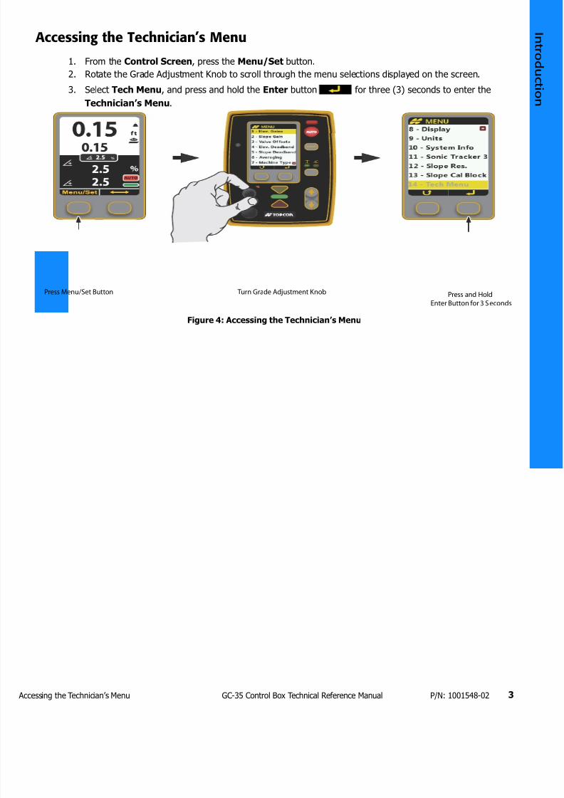
7172019 GC 35 Tecnical Reference Manual
httpslidepdfcomreaderfullgc-35-tecnical-reference-manual 1123
ccessing the Technicianrsquos Menu 3GC-35 Control Box Technical Reference Manual PN 1001548-02
Accessing the Technicianrsquos Menu
1 From the Control Screen press the MenuSet button
2 Rotate the Grade Adjustment Knob to scroll through the menu selections displayed on the screen
3 Select Tech Menu and press and hold the Enter button for three (3) seconds to enter the
Technicianrsquos Menu
Figure 4 Accessing the Technicianrsquos Menu
Press MenuSet Button Turn Grade Adjustment Knob Press and Hold
Enter Button for 3 Seconds
7172019 GC 35 Tecnical Reference Manual
httpslidepdfcomreaderfullgc-35-tecnical-reference-manual 1223
Technicianrsquos Menu 9GC-35 Control Box Technical Reference Manual PN 1001548-02
bull bull bull bull bull bull
Technicianrsquos Menu
This chapter describes the Technicianrsquos Menu items and their default factory settings
Table 1 lists the available menus
Table 1 Technicianrsquos Menu Settings
Menu Item Range Default Factory Setting
Configuration External 0ndash31 Custom External
Averaging 1 ndash 100 50
Valve Type Solenoid ProportionalDanfoss Pulse WidthModulated
Proportional
Valve Drive Sink Source Sink
Dither Amplitude 0ndash15 4
Dither Frequency 0ndash105 42
Frequency 1ndash13Hz
225ndash1950Hz
5Hz
Max Current 067ndash48 Amps 175 Amps
Hour Read only Hours 00
Hours Auto 00
External Auto On Off Invert Off
Auto Power Up (Paver only) On Off On
Esup2 Reset Cancel Reset Cancel
Lock Menu Level 1 - Unlocked
Level 2 - Moderate
Level 3 - Restricted
Level 1 - Unlocked
Elevation Gains Raise 1 ndash 200 Raise 25
Lower 1 ndash 200 Lower 25
Slope Gain 1 ndash 100 25
Valve Offsets Raise 1 ndash 999 Raise 135
Lower 1 ndash 999 Lower 135
Elevation Deadband 1 ndash 30 mm 3 mm
Slope Deadband 0025 ndash 075 0075
Working Window 0ndash500 Off 020 ft
Slope Working Window 01-100 20
Smartlink Slope 0 - 100 Slope 0
Elevation 0 - 100 Elevation 0
7172019 GC 35 Tecnical Reference Manual
httpslidepdfcomreaderfullgc-35-tecnical-reference-manual 1323
onfiguration 10GC-35 Control Box Technical Reference Manual PN 1001548-02
Configuration
This setting selects a valve drive configuration and has up to 32 preprogrammed configurations to select from You may also create a custom configuration
Configuration Value Range External 0-31 Custom
Default External
bull External ndash Upon power up the control box looks for an external configuration resistor between pins Land K of the 11 pin bulkhead connector and defaults to the listed configuration table for valve control
The configuration number displays on the control box LCD when the box is turned onbull Value between 0-31 ndash The control box defaults to the valve control parameters for this number listed inthe configuration chart (see Table 2 on page 10) The configuration number displays on the control boxLCD when the box is turned on
bull Custom ndash Create a custom valve control configuration by setting the Valve Type Current DirectionCurrent Limit Frequency (for PWM modes and Solenoid) Dither Amplitude (except Solenoid mode) andDither Frequency (except Solenoid mode)
Configuration Codes
Table 2 lists available configurations
Table 2 Configuration Codes
ConfigResistor
(ohms)
Drive Type Current Direction Dither Amplitude Dither Freq Freq Hz Current Limit
0 0 Sol Sink None None Adj None
1 77
2 160
3 249
4 341
5 441 Sol Source None None Adj None
6 560 Sol Source None None Adj None
7 670
8 800 Sol Source None None Adj None
9 940 Sol Source None None Adj None10 1100 Sol Sink None None Adj None
11 1260 Sol Source None None Adj
12 1445
14 1890
15 2140 Pro Cur Source 6 42 NA 175A
17 2760 Sol Sink None None Adj None
18 3140 Sol Sink None None Adj None
19 3583 Sol Source None None Adj None
20 4104 Sol Sink None None Adj None
21 4725 Sol Sink None None Adj None
22 5480 Sol
23 6414
26 11310 Sol Source None None Adj None
27 14440
28 19440
29 28670
30 51500 Pro Cur Source 12 42 NA 175A
31 open Pro Cur Sink 6 42 NA 175A
7172019 GC 35 Tecnical Reference Manual
httpslidepdfcomreaderfullgc-35-tecnical-reference-manual 1423
veraging 11GC-35 Control Box Technical Reference Manual PN 1001548-02
Averaging
Averaging changes the amount of dampening or filtering applied to the laser receiver or elevation sensormeasurements Averaging can be thought of as the time period over which a running average of the elevationmeasurement is calculated
Averaging Value Range 1ndash100
Default 50
A lower value averages fewer elevation measurements allowing the system to react more quickly to grade
changes
A larger value averages more elevation measurements making the system less reactive to fluctuations in gradesuch as with laser ldquobeam bouncerdquo on windy days
Valve Type
Valve Type allows you to select the type of valves used on your machine
Valve Type Value Range Solenoid Servo Proportional Danfoss Pulse PWMDefault Proportional
The following sections describe each of these valve types
Proportional Current
Proportional Current provides a current regulated proportional output and is the preferred setting forproportional valves
A percentage of the total current setting is calculated based on the gain setting and given grade correctionProportional Current control applies full machine voltage to the valve coil until the desired current is reachedthen the voltage is turned off When the current drops below the desired value the process is repeated
Proportional Pulse Width Modulated
Proportional Pulse Width Modulated provides a pulse width regulated proportional output
A percentage of the total duty cycle is calculated based on the gain setting and the given grade correction PulseWidth Modulation cycles the output voltage on and off at the desired duty cycle
Solenoid
Solenoid operates the same as PWM mode except set up specifically for the lower frequency solenoid valves
Danfoss
Danfoss provides a proportional voltage output to drive the specific requirements of the Danfoss brand ofproportional valves In this mode switched power (Vsw) and ground connect to the Danfoss valve through thevalve cable and the Raise output pin of the control box controls the reference signal to the valve In a neutral(no grade) correction output the reference signal is held at half of the switched voltage For example if a 12volt system produced 13 volts on the Vsw line 65 volts are held on the reference output for a no correctionsignal
bull For a raise correction signal the control box increases the reference voltage from 65 to a maximum of975 V
Averaging does not affect slope control
7172019 GC 35 Tecnical Reference Manual
httpslidepdfcomreaderfullgc-35-tecnical-reference-manual 1523
alve Drive 12GC-35 Control Box Technical Reference Manual PN 1001548-02
bull For a lower output signal the control box decreases the reference voltage to a minimum of 325 V
Valve Drive
Valve Drive selects the current direction of the valves on the machine
Valve Drive Value Range Sink Source
Select Sink if the valve has a permanent positive connection and needs a switched negative connection (thecontrol box sinks current)
Select Source if the valve has a permanent ground (negative) connection and needs a switched positiveconnection (the control box sources current)
Dither Amplitude
Dither Amplitude allows you to select the amount of dither to apply to the valve
Dither is a continuous low frequency ldquopulserdquo applied to the valve drive signal for proportional valves to keep thevalversquos spool from sticking
Dither Amplitude Value Range 0ndash15
Dither Amplitude is a percentage of full current for the Proportional Current valve type or duty cycle for thePWM valve type Dither does not apply for Solenoid Danfoss or Servo valve types
Dither Frequency
Dither Frequency adjusts the frequency of the dither in cycles per second
Dither Frequency Value Range 0ndash105 Hz
Frequency
Frequency adjusts the number of pulses sent to control valves in one secondFrequency Value Range 1ndash13 Hz 225ndash1950 Hz
The frequency value is adjustable from 1 to 13 Hz for Solenoid valves On Pulse Width Modulated mode valvesthe range is 225 to 1950 Hz
Max Current
Max Current adjusts the maximum valve drive current that the control box outputs when using ProportionalCurrent valve output mode and the over-current trip level for other valve types
Current Limit Value Range 067ndash48 Amps
If a Danfoss valve sees a reference voltage greater than 75 of Vsw or below 25 of Vsw the valvedefaults to an ldquoerrorrdquo state and the valve is held in the neutral position
Frequency does not apply for Proportional Current and Danfoss valve types
Changing the Frequency has an effect on the Offset Check the Offset after changing theFrequency
7172019 GC 35 Tecnical Reference Manual
httpslidepdfcomreaderfullgc-35-tecnical-reference-manual 1623
our 13GC-35 Control Box Technical Reference Manual PN 1001548-02
Hour
Hour displays the amount of hours the control box has been operating and the amount of hours the control boxhas been operating in Automatic
Hour Settings No settings (read only)
External Auto
External Auto disables or enables an external automanual switch
External Auto Settings OnOffInvert
If On is selected the system requires both an external AM switch and activation of the Control Boxrsquos Autobutton to switch the system in and out of Automatic control Activate the external AM switch by connectingpin E of the 11 PIN bulkhead to ground
If you select Invert connecting pin E to ground takes the system out of Automatic control Automatic controlactivates only when pin E is connected to power such as when connecting to an in-motion switch
Auto Power (Paver Only)
The Auto Power setting allows the system to automatically power up to the last used mode
Auto Power Settings OnOff
When the Auto Power setting is On the system powers up in the last mode seen before power down (Auto orManual) For example the paver is in automatic control is shut down and then powered up once more Thepaver is now ready to pave in Auto
When the Auto Power setting is Off the operator must press the Auto button to return to Auto after a powerdown
Esup2 Reset
Esup2 Reset reconfigures the system to factory settings
Esup2 Reset Settings Range CancelReset
To reset all settings in the Performance Menu and the Technician Menu to factory defaults select Reset and press and hold the Enter button for three (3) seconds
To cancel and return to the previous screen select Cancel
Lock Menu
The Lock-Out Setting allows certain Performance Settings in the Performance Menu to be made inaccessibleto the operator (see ldquoPaver Lock Menu Settingsrdquo on page 14)
If the Auto Power setting is On the machine powers up in Auto any time it was shut down in AutoOnly use Auto Power On in asphalt paver applications
Setting Auto Power to On for a machine other than asphalt pavers is not recommended Seriousinjury to operators or bystanders from unexpected machine movement could result
If you select Reset the Control Box reverts your custom Control Box settings back to their factorydefault values
7172019 GC 35 Tecnical Reference Manual
httpslidepdfcomreaderfullgc-35-tecnical-reference-manual 1723
levation Gains (Raise and Lower) 14GC-35 Control Box Technical Reference Manual PN 1001548-02
Lock-Out Value Range Level 1 - Unlocked Level2 - Moderate Level 3 - Restricted
bull Level 1 ndash all Performance Menu items are accessible to the operator
bull Level 2ndash some items no longer appear in the Performance Menu and are only accessible in theTechnicianrsquos Menu
bull Level 3 ndash additional items no longer appear in the Performance Menu and are only accessible in theTechnicianrsquos Menu
Lock Menu Settings
Table 3 lists the settings that can be locked out (made unavailable)
Elevation Gains (Raise and Lower)
Elevation Gains determines the speed at which your Topcon P-32 System allows the tow point cylinders to adjustto a change in elevation For faster hydraulic response increase the gain value For slower hydraulic responsedecrease the gain value
The objective is to set the gain so the screed reacts to the change in grade quickly but without ldquoovershootingrdquothe new elevation
Gain Elevation Value Range 1-200
Table 3 Paver Lock Menu Settings
Performance Menu Item Level 1 - Unlocked Level 2 - Moderate Level 3 - Restricted
1 Elevation Gains Available Available Locked
2 Slope Gain Available Available Locked
3 Valve Offsets Available Available Locked
4 Elevation Deadband Available Locked Locked
5 Slope Deadband Available Locked Locked
6 Averaging Available Locked Locked
7 Machine Type Available Available Available
8 Display Available Available Available
9 Units Available Available Available
10 System Info Available Available Available
11 Sonic Tracker 3 Available Available Available
12 Slope Resolution Available Available Available
13 Slope Cal Block Available Available Locked
14 Tech Menu Available Available Available
Before setting the Elevation Gain make sure the machines hydraulic flow controls valves are adjustedfor proper cylinder speed according to the manufacturers recommendations
7172019 GC 35 Tecnical Reference Manual
httpslidepdfcomreaderfullgc-35-tecnical-reference-manual 1823
lope Gain 15GC-35 Control Box Technical Reference Manual PN 1001548-02
Slope Gain
This setting determines the speed at which your Topcon P-32 System allows the tow point cylinders to adjustto a change in slope For faster hydraulic response increase the gain value For slower hydraulic responsedecrease the gain value
The objective is to set the gain so the screed reacts to the change in grade quickly but without ldquoovershootingrdquoOn-Grade Slope Gain should not be set at a higher value than the Elevation Gain on the other side of the paver
Gain Elevation Value Range 1-100
Valve Offsets (Raise and Lower)
Valve Offsets is the minimum amount of electrical signals sent to the valve which causes the hydraulic cylinderto move If the valve offset is too small the sensor will not reach On-Grade Likewise if the valve offset valueis too large the sensor will move too much and overshoot On-Grade
Run the Paver until the hydraulic oil is at normal operating temperature before setting the valve offsets Oncethey are set you should not need to readjust the valve offsets unless the Control Box is moved to a new paveror the hydraulic performance changes
Valve Offset Value Range (Raise and Lower) 1 - 999
Elevation Deadband
Elevation Deadband is the area of the Working Window that is On-Grade While the reference is within that areathe paverrsquos valves are idle (closed) Therefore the wider the Elevation Deadband (On-Grade area) the more areference can move up or down without a correction being initiated Once the signal from the reference is outof the deadband your control box drives the hydraulics to place the reference back in the center of thedeadband
Deadband Elevation Value Range 1ndash30 mm
Before setting the Slope Gain ensure the machines hydraulic flow control valves are adjusted forproper cylinder speed according to the manufacturers recommendations
Do not set slope gain at a higher value than the elevation gain on the other side of the paver A highervalue may cause the slope to be over reactive
Set the Valve Offsets before adjusting elevation and slope gains and averaging
The offset value on one side of the paver may differ from the offset value on the other side of thepaver You must verify the offset values before swapping boxes Use the ldquoLeftrdquo and ldquoRightrdquo labelsprovided
Never attempt to use Valve Offsets to compensate for a slower raise or lower speed of your hydraulicvalves as it causes undershooting or overshooting in Slope Mode and can adversely affect the qualityof the mat
Select the amount of Elevation Deadband carefully Too small of an Elevation Deadband causes thetow point cylinder to constantly hunt up and down while the sensor tries to find On-Grade Too largeof an Elevation Deadband does not allow the sensor to send grade corrections to the values causingunwanted variations in mat thickness
7172019 GC 35 Tecnical Reference Manual
httpslidepdfcomreaderfullgc-35-tecnical-reference-manual 1923
lope Deadband 16GC-35 Control Box Technical Reference Manual PN 1001548-02
Slope Deadband
Slope Deadband defines the size of the on-grade area where no valve corrections are made
Deadband Slope Value Range 0025ndash075
The wider the Slope Deadband the greater the slope can vary without initiating a correction
For example if the operator is grading at a 20 slope and the Slope Deadband is set at 10 the system
reads on-grade anywhere from 195 slope to 205 slope The lower the percentage the tighter the SlopeDeadband
Once the slope signal is out of the Slope Deadband System Five drives the hydraulics back within the SlopeDeadband
Working Window Adjustment
Working Window Adjustment adjusts the working window of the sonic tracker (Figure 5)
Working Window Settings 0ndash500 Off
Default 020
The default setting is 020 which gives 020 ft (61 mm) above and below on-grade Setting the value to Offcompletely disables the working window and allows any target to be seen
7172019 GC 35 Tecnical Reference Manual
httpslidepdfcomreaderfullgc-35-tecnical-reference-manual 2023
lope Working Window 17GC-35 Control Box Technical Reference Manual PN 1001548-02
Figure 5 Sonic Tracker Working Window
Slope Working Window
Slope Working Window adjusts the working window of the Slope Sensor (Figure 6)
Slope Working Window Value Range 01 - 100 Off
Default 20
The default setting is 20 which gives 20 slope above and below ongrade Setting the value to Off completelydisables the working window
Out of Range
Ongrade
Flashing UpDown Arrow
Solid UpDown Arrow
20rsquo
20rsquo
20rsquo
20rsquo
Working
Window
(Adjustable)
ST-3 Sonic Tracker II
When using the Sonic Tracker II to follow a stringline curb or other elevated reference there is adanger of making an unwanted cut if the Trackerrsquos sonic cone moves away from the target This canoccur if the working window is either off or set as high as the distance between the reference and theground Setting the working window to the default value of 20 (020ft) prevents the automatic controlfrom making such a reaction due to a loss of the target
7172019 GC 35 Tecnical Reference Manual
httpslidepdfcomreaderfullgc-35-tecnical-reference-manual 2123
martlink (Elevation and Slope) 18GC-35 Control Box Technical Reference Manual PN 1001548-02
Figure 6 Slope Working Window
Smartlink (Elevation and Slope)
Smartlink allows the Control Box to send a percentage of the slopeelevation correction on one side of themachine to the Control Box on the other side of the machine preemptively raising or lowering that hydrauliccylinder to keep the machine at the correct grade Smartlink decreases the lag in correction that can occur onone side of the machine as the second Control Box begins moving the valve without having to wait for thesensor on the other side of the machine to detect and correct for a change in elevationslope
Smartlink Value Range 0 - 100
Default 0
Out of Range
Working Window (Adjustable)
Ongrade
20
20
Ongrade
20
20
7172019 GC 35 Tecnical Reference Manual
httpslidepdfcomreaderfullgc-35-tecnical-reference-manual 2223
Warranty 19GC-35 Control Box Technical Reference Manual PN 1001548-02
bull bull bull bull bull bull
Warranty
Topcon laser and electronic positioning equipment are guaranteed against defective material and workmanshipunder normal use and application consistent with this Manual The equipment is guaranteed for the period indicatedon the warranty card accompanying the product starting from the date that the product is sold to the originalpurchaser by Topconrsquos Authorized Dealers1
During the warranty period Topcon will at its option repair or replace this product at no additional charge Repairparts and replacement products will be furnished on an exchange basis and will be either reconditioned or new Thislimited warranty does not include service to repair damage to the product resulting from an accident disastermisuses abuse or modification of the product
Warranty service may be obtained from an authorized Topcon warranty service dealer If this product is deliveredby mail purchaser agrees to insure the product or assume the risk of loss or damage in transit to prepay shippingcharges to the warranty service location and to use the original shipping container or equivalent A letter shouldaccompany the package furnishing a description of the problem andor defect
The purchaserrsquos sole remedy shall be replacement as provided above In no event shall Topcon be liable for anydamages or other claim including any claim for lost profits lost savings or other incidental or consequential damagesarising out of the use of or inability to use the product
1 The warranty against defects in a Topcon battery charger or cable is 90 days
7172019 GC 35 Tecnical Reference Manual
httpslidepdfcomreaderfullgc-35-tecnical-reference-manual 2323
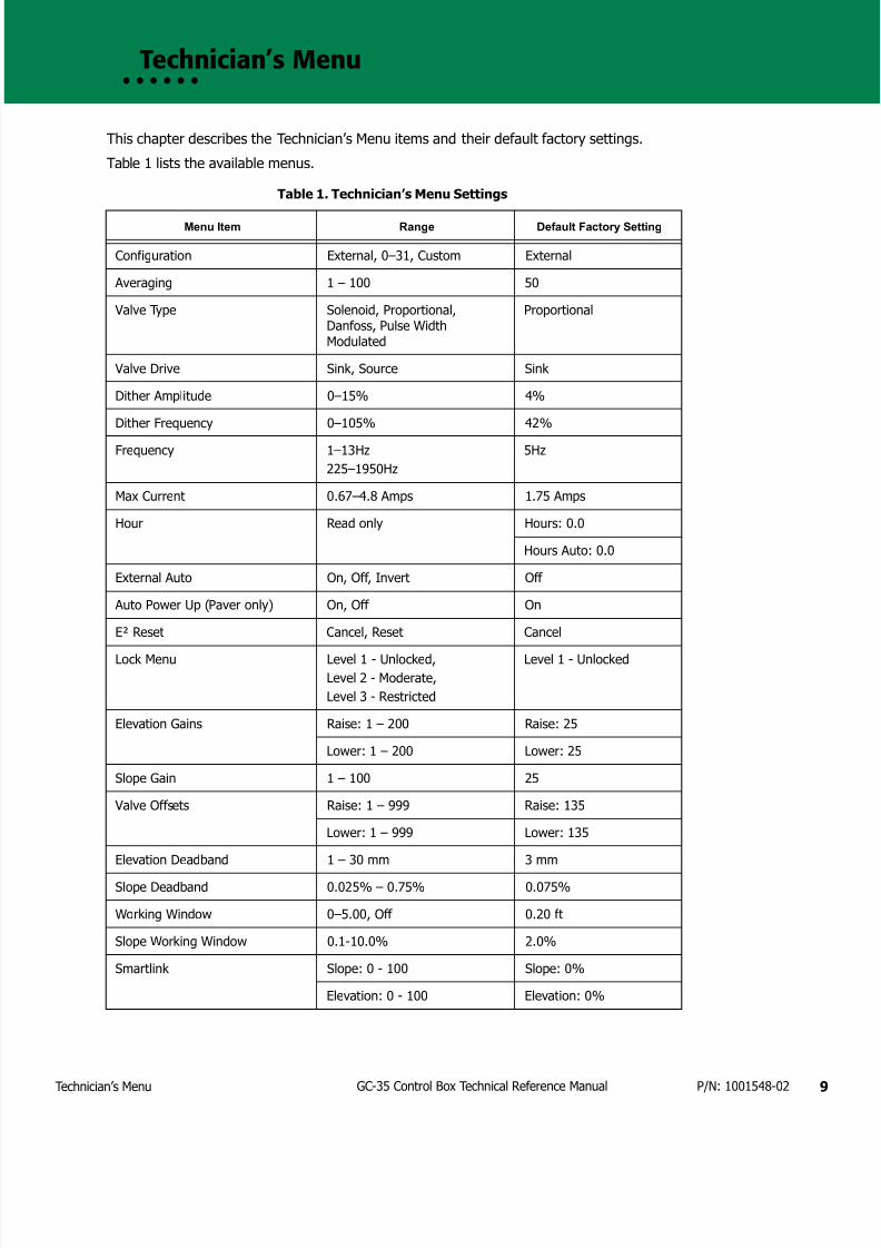
7172019 GC 35 Tecnical Reference Manual
httpslidepdfcomreaderfullgc-35-tecnical-reference-manual 1223
Technicianrsquos Menu 9GC-35 Control Box Technical Reference Manual PN 1001548-02
bull bull bull bull bull bull
Technicianrsquos Menu
This chapter describes the Technicianrsquos Menu items and their default factory settings
Table 1 lists the available menus
Table 1 Technicianrsquos Menu Settings
Menu Item Range Default Factory Setting
Configuration External 0ndash31 Custom External
Averaging 1 ndash 100 50
Valve Type Solenoid ProportionalDanfoss Pulse WidthModulated
Proportional
Valve Drive Sink Source Sink
Dither Amplitude 0ndash15 4
Dither Frequency 0ndash105 42
Frequency 1ndash13Hz
225ndash1950Hz
5Hz
Max Current 067ndash48 Amps 175 Amps
Hour Read only Hours 00
Hours Auto 00
External Auto On Off Invert Off
Auto Power Up (Paver only) On Off On
Esup2 Reset Cancel Reset Cancel
Lock Menu Level 1 - Unlocked
Level 2 - Moderate
Level 3 - Restricted
Level 1 - Unlocked
Elevation Gains Raise 1 ndash 200 Raise 25
Lower 1 ndash 200 Lower 25
Slope Gain 1 ndash 100 25
Valve Offsets Raise 1 ndash 999 Raise 135
Lower 1 ndash 999 Lower 135
Elevation Deadband 1 ndash 30 mm 3 mm
Slope Deadband 0025 ndash 075 0075
Working Window 0ndash500 Off 020 ft
Slope Working Window 01-100 20
Smartlink Slope 0 - 100 Slope 0
Elevation 0 - 100 Elevation 0
7172019 GC 35 Tecnical Reference Manual
httpslidepdfcomreaderfullgc-35-tecnical-reference-manual 1323
onfiguration 10GC-35 Control Box Technical Reference Manual PN 1001548-02
Configuration
This setting selects a valve drive configuration and has up to 32 preprogrammed configurations to select from You may also create a custom configuration
Configuration Value Range External 0-31 Custom
Default External
bull External ndash Upon power up the control box looks for an external configuration resistor between pins Land K of the 11 pin bulkhead connector and defaults to the listed configuration table for valve control
The configuration number displays on the control box LCD when the box is turned onbull Value between 0-31 ndash The control box defaults to the valve control parameters for this number listed inthe configuration chart (see Table 2 on page 10) The configuration number displays on the control boxLCD when the box is turned on
bull Custom ndash Create a custom valve control configuration by setting the Valve Type Current DirectionCurrent Limit Frequency (for PWM modes and Solenoid) Dither Amplitude (except Solenoid mode) andDither Frequency (except Solenoid mode)
Configuration Codes
Table 2 lists available configurations
Table 2 Configuration Codes
ConfigResistor
(ohms)
Drive Type Current Direction Dither Amplitude Dither Freq Freq Hz Current Limit
0 0 Sol Sink None None Adj None
1 77
2 160
3 249
4 341
5 441 Sol Source None None Adj None
6 560 Sol Source None None Adj None
7 670
8 800 Sol Source None None Adj None
9 940 Sol Source None None Adj None10 1100 Sol Sink None None Adj None
11 1260 Sol Source None None Adj
12 1445
14 1890
15 2140 Pro Cur Source 6 42 NA 175A
17 2760 Sol Sink None None Adj None
18 3140 Sol Sink None None Adj None
19 3583 Sol Source None None Adj None
20 4104 Sol Sink None None Adj None
21 4725 Sol Sink None None Adj None
22 5480 Sol
23 6414
26 11310 Sol Source None None Adj None
27 14440
28 19440
29 28670
30 51500 Pro Cur Source 12 42 NA 175A
31 open Pro Cur Sink 6 42 NA 175A
7172019 GC 35 Tecnical Reference Manual
httpslidepdfcomreaderfullgc-35-tecnical-reference-manual 1423
veraging 11GC-35 Control Box Technical Reference Manual PN 1001548-02
Averaging
Averaging changes the amount of dampening or filtering applied to the laser receiver or elevation sensormeasurements Averaging can be thought of as the time period over which a running average of the elevationmeasurement is calculated
Averaging Value Range 1ndash100
Default 50
A lower value averages fewer elevation measurements allowing the system to react more quickly to grade
changes
A larger value averages more elevation measurements making the system less reactive to fluctuations in gradesuch as with laser ldquobeam bouncerdquo on windy days
Valve Type
Valve Type allows you to select the type of valves used on your machine
Valve Type Value Range Solenoid Servo Proportional Danfoss Pulse PWMDefault Proportional
The following sections describe each of these valve types
Proportional Current
Proportional Current provides a current regulated proportional output and is the preferred setting forproportional valves
A percentage of the total current setting is calculated based on the gain setting and given grade correctionProportional Current control applies full machine voltage to the valve coil until the desired current is reachedthen the voltage is turned off When the current drops below the desired value the process is repeated
Proportional Pulse Width Modulated
Proportional Pulse Width Modulated provides a pulse width regulated proportional output
A percentage of the total duty cycle is calculated based on the gain setting and the given grade correction PulseWidth Modulation cycles the output voltage on and off at the desired duty cycle
Solenoid
Solenoid operates the same as PWM mode except set up specifically for the lower frequency solenoid valves
Danfoss
Danfoss provides a proportional voltage output to drive the specific requirements of the Danfoss brand ofproportional valves In this mode switched power (Vsw) and ground connect to the Danfoss valve through thevalve cable and the Raise output pin of the control box controls the reference signal to the valve In a neutral(no grade) correction output the reference signal is held at half of the switched voltage For example if a 12volt system produced 13 volts on the Vsw line 65 volts are held on the reference output for a no correctionsignal
bull For a raise correction signal the control box increases the reference voltage from 65 to a maximum of975 V
Averaging does not affect slope control
7172019 GC 35 Tecnical Reference Manual
httpslidepdfcomreaderfullgc-35-tecnical-reference-manual 1523
alve Drive 12GC-35 Control Box Technical Reference Manual PN 1001548-02
bull For a lower output signal the control box decreases the reference voltage to a minimum of 325 V
Valve Drive
Valve Drive selects the current direction of the valves on the machine
Valve Drive Value Range Sink Source
Select Sink if the valve has a permanent positive connection and needs a switched negative connection (thecontrol box sinks current)
Select Source if the valve has a permanent ground (negative) connection and needs a switched positiveconnection (the control box sources current)
Dither Amplitude
Dither Amplitude allows you to select the amount of dither to apply to the valve
Dither is a continuous low frequency ldquopulserdquo applied to the valve drive signal for proportional valves to keep thevalversquos spool from sticking
Dither Amplitude Value Range 0ndash15
Dither Amplitude is a percentage of full current for the Proportional Current valve type or duty cycle for thePWM valve type Dither does not apply for Solenoid Danfoss or Servo valve types
Dither Frequency
Dither Frequency adjusts the frequency of the dither in cycles per second
Dither Frequency Value Range 0ndash105 Hz
Frequency
Frequency adjusts the number of pulses sent to control valves in one secondFrequency Value Range 1ndash13 Hz 225ndash1950 Hz
The frequency value is adjustable from 1 to 13 Hz for Solenoid valves On Pulse Width Modulated mode valvesthe range is 225 to 1950 Hz
Max Current
Max Current adjusts the maximum valve drive current that the control box outputs when using ProportionalCurrent valve output mode and the over-current trip level for other valve types
Current Limit Value Range 067ndash48 Amps
If a Danfoss valve sees a reference voltage greater than 75 of Vsw or below 25 of Vsw the valvedefaults to an ldquoerrorrdquo state and the valve is held in the neutral position
Frequency does not apply for Proportional Current and Danfoss valve types
Changing the Frequency has an effect on the Offset Check the Offset after changing theFrequency
7172019 GC 35 Tecnical Reference Manual
httpslidepdfcomreaderfullgc-35-tecnical-reference-manual 1623
our 13GC-35 Control Box Technical Reference Manual PN 1001548-02
Hour
Hour displays the amount of hours the control box has been operating and the amount of hours the control boxhas been operating in Automatic
Hour Settings No settings (read only)
External Auto
External Auto disables or enables an external automanual switch
External Auto Settings OnOffInvert
If On is selected the system requires both an external AM switch and activation of the Control Boxrsquos Autobutton to switch the system in and out of Automatic control Activate the external AM switch by connectingpin E of the 11 PIN bulkhead to ground
If you select Invert connecting pin E to ground takes the system out of Automatic control Automatic controlactivates only when pin E is connected to power such as when connecting to an in-motion switch
Auto Power (Paver Only)
The Auto Power setting allows the system to automatically power up to the last used mode
Auto Power Settings OnOff
When the Auto Power setting is On the system powers up in the last mode seen before power down (Auto orManual) For example the paver is in automatic control is shut down and then powered up once more Thepaver is now ready to pave in Auto
When the Auto Power setting is Off the operator must press the Auto button to return to Auto after a powerdown
Esup2 Reset
Esup2 Reset reconfigures the system to factory settings
Esup2 Reset Settings Range CancelReset
To reset all settings in the Performance Menu and the Technician Menu to factory defaults select Reset and press and hold the Enter button for three (3) seconds
To cancel and return to the previous screen select Cancel
Lock Menu
The Lock-Out Setting allows certain Performance Settings in the Performance Menu to be made inaccessibleto the operator (see ldquoPaver Lock Menu Settingsrdquo on page 14)
If the Auto Power setting is On the machine powers up in Auto any time it was shut down in AutoOnly use Auto Power On in asphalt paver applications
Setting Auto Power to On for a machine other than asphalt pavers is not recommended Seriousinjury to operators or bystanders from unexpected machine movement could result
If you select Reset the Control Box reverts your custom Control Box settings back to their factorydefault values
7172019 GC 35 Tecnical Reference Manual
httpslidepdfcomreaderfullgc-35-tecnical-reference-manual 1723
levation Gains (Raise and Lower) 14GC-35 Control Box Technical Reference Manual PN 1001548-02
Lock-Out Value Range Level 1 - Unlocked Level2 - Moderate Level 3 - Restricted
bull Level 1 ndash all Performance Menu items are accessible to the operator
bull Level 2ndash some items no longer appear in the Performance Menu and are only accessible in theTechnicianrsquos Menu
bull Level 3 ndash additional items no longer appear in the Performance Menu and are only accessible in theTechnicianrsquos Menu
Lock Menu Settings
Table 3 lists the settings that can be locked out (made unavailable)
Elevation Gains (Raise and Lower)
Elevation Gains determines the speed at which your Topcon P-32 System allows the tow point cylinders to adjustto a change in elevation For faster hydraulic response increase the gain value For slower hydraulic responsedecrease the gain value
The objective is to set the gain so the screed reacts to the change in grade quickly but without ldquoovershootingrdquothe new elevation
Gain Elevation Value Range 1-200
Table 3 Paver Lock Menu Settings
Performance Menu Item Level 1 - Unlocked Level 2 - Moderate Level 3 - Restricted
1 Elevation Gains Available Available Locked
2 Slope Gain Available Available Locked
3 Valve Offsets Available Available Locked
4 Elevation Deadband Available Locked Locked
5 Slope Deadband Available Locked Locked
6 Averaging Available Locked Locked
7 Machine Type Available Available Available
8 Display Available Available Available
9 Units Available Available Available
10 System Info Available Available Available
11 Sonic Tracker 3 Available Available Available
12 Slope Resolution Available Available Available
13 Slope Cal Block Available Available Locked
14 Tech Menu Available Available Available
Before setting the Elevation Gain make sure the machines hydraulic flow controls valves are adjustedfor proper cylinder speed according to the manufacturers recommendations
7172019 GC 35 Tecnical Reference Manual
httpslidepdfcomreaderfullgc-35-tecnical-reference-manual 1823
lope Gain 15GC-35 Control Box Technical Reference Manual PN 1001548-02
Slope Gain
This setting determines the speed at which your Topcon P-32 System allows the tow point cylinders to adjustto a change in slope For faster hydraulic response increase the gain value For slower hydraulic responsedecrease the gain value
The objective is to set the gain so the screed reacts to the change in grade quickly but without ldquoovershootingrdquoOn-Grade Slope Gain should not be set at a higher value than the Elevation Gain on the other side of the paver
Gain Elevation Value Range 1-100
Valve Offsets (Raise and Lower)
Valve Offsets is the minimum amount of electrical signals sent to the valve which causes the hydraulic cylinderto move If the valve offset is too small the sensor will not reach On-Grade Likewise if the valve offset valueis too large the sensor will move too much and overshoot On-Grade
Run the Paver until the hydraulic oil is at normal operating temperature before setting the valve offsets Oncethey are set you should not need to readjust the valve offsets unless the Control Box is moved to a new paveror the hydraulic performance changes
Valve Offset Value Range (Raise and Lower) 1 - 999
Elevation Deadband
Elevation Deadband is the area of the Working Window that is On-Grade While the reference is within that areathe paverrsquos valves are idle (closed) Therefore the wider the Elevation Deadband (On-Grade area) the more areference can move up or down without a correction being initiated Once the signal from the reference is outof the deadband your control box drives the hydraulics to place the reference back in the center of thedeadband
Deadband Elevation Value Range 1ndash30 mm
Before setting the Slope Gain ensure the machines hydraulic flow control valves are adjusted forproper cylinder speed according to the manufacturers recommendations
Do not set slope gain at a higher value than the elevation gain on the other side of the paver A highervalue may cause the slope to be over reactive
Set the Valve Offsets before adjusting elevation and slope gains and averaging
The offset value on one side of the paver may differ from the offset value on the other side of thepaver You must verify the offset values before swapping boxes Use the ldquoLeftrdquo and ldquoRightrdquo labelsprovided
Never attempt to use Valve Offsets to compensate for a slower raise or lower speed of your hydraulicvalves as it causes undershooting or overshooting in Slope Mode and can adversely affect the qualityof the mat
Select the amount of Elevation Deadband carefully Too small of an Elevation Deadband causes thetow point cylinder to constantly hunt up and down while the sensor tries to find On-Grade Too largeof an Elevation Deadband does not allow the sensor to send grade corrections to the values causingunwanted variations in mat thickness
7172019 GC 35 Tecnical Reference Manual
httpslidepdfcomreaderfullgc-35-tecnical-reference-manual 1923
lope Deadband 16GC-35 Control Box Technical Reference Manual PN 1001548-02
Slope Deadband
Slope Deadband defines the size of the on-grade area where no valve corrections are made
Deadband Slope Value Range 0025ndash075
The wider the Slope Deadband the greater the slope can vary without initiating a correction
For example if the operator is grading at a 20 slope and the Slope Deadband is set at 10 the system
reads on-grade anywhere from 195 slope to 205 slope The lower the percentage the tighter the SlopeDeadband
Once the slope signal is out of the Slope Deadband System Five drives the hydraulics back within the SlopeDeadband
Working Window Adjustment
Working Window Adjustment adjusts the working window of the sonic tracker (Figure 5)
Working Window Settings 0ndash500 Off
Default 020
The default setting is 020 which gives 020 ft (61 mm) above and below on-grade Setting the value to Offcompletely disables the working window and allows any target to be seen
7172019 GC 35 Tecnical Reference Manual
httpslidepdfcomreaderfullgc-35-tecnical-reference-manual 2023
lope Working Window 17GC-35 Control Box Technical Reference Manual PN 1001548-02
Figure 5 Sonic Tracker Working Window
Slope Working Window
Slope Working Window adjusts the working window of the Slope Sensor (Figure 6)
Slope Working Window Value Range 01 - 100 Off
Default 20
The default setting is 20 which gives 20 slope above and below ongrade Setting the value to Off completelydisables the working window
Out of Range
Ongrade
Flashing UpDown Arrow
Solid UpDown Arrow
20rsquo
20rsquo
20rsquo
20rsquo
Working
Window
(Adjustable)
ST-3 Sonic Tracker II
When using the Sonic Tracker II to follow a stringline curb or other elevated reference there is adanger of making an unwanted cut if the Trackerrsquos sonic cone moves away from the target This canoccur if the working window is either off or set as high as the distance between the reference and theground Setting the working window to the default value of 20 (020ft) prevents the automatic controlfrom making such a reaction due to a loss of the target
7172019 GC 35 Tecnical Reference Manual
httpslidepdfcomreaderfullgc-35-tecnical-reference-manual 2123
martlink (Elevation and Slope) 18GC-35 Control Box Technical Reference Manual PN 1001548-02
Figure 6 Slope Working Window
Smartlink (Elevation and Slope)
Smartlink allows the Control Box to send a percentage of the slopeelevation correction on one side of themachine to the Control Box on the other side of the machine preemptively raising or lowering that hydrauliccylinder to keep the machine at the correct grade Smartlink decreases the lag in correction that can occur onone side of the machine as the second Control Box begins moving the valve without having to wait for thesensor on the other side of the machine to detect and correct for a change in elevationslope
Smartlink Value Range 0 - 100
Default 0
Out of Range
Working Window (Adjustable)
Ongrade
20
20
Ongrade
20
20
7172019 GC 35 Tecnical Reference Manual
httpslidepdfcomreaderfullgc-35-tecnical-reference-manual 2223
Warranty 19GC-35 Control Box Technical Reference Manual PN 1001548-02
bull bull bull bull bull bull
Warranty
Topcon laser and electronic positioning equipment are guaranteed against defective material and workmanshipunder normal use and application consistent with this Manual The equipment is guaranteed for the period indicatedon the warranty card accompanying the product starting from the date that the product is sold to the originalpurchaser by Topconrsquos Authorized Dealers1
During the warranty period Topcon will at its option repair or replace this product at no additional charge Repairparts and replacement products will be furnished on an exchange basis and will be either reconditioned or new Thislimited warranty does not include service to repair damage to the product resulting from an accident disastermisuses abuse or modification of the product
Warranty service may be obtained from an authorized Topcon warranty service dealer If this product is deliveredby mail purchaser agrees to insure the product or assume the risk of loss or damage in transit to prepay shippingcharges to the warranty service location and to use the original shipping container or equivalent A letter shouldaccompany the package furnishing a description of the problem andor defect
The purchaserrsquos sole remedy shall be replacement as provided above In no event shall Topcon be liable for anydamages or other claim including any claim for lost profits lost savings or other incidental or consequential damagesarising out of the use of or inability to use the product
1 The warranty against defects in a Topcon battery charger or cable is 90 days
7172019 GC 35 Tecnical Reference Manual
httpslidepdfcomreaderfullgc-35-tecnical-reference-manual 2323
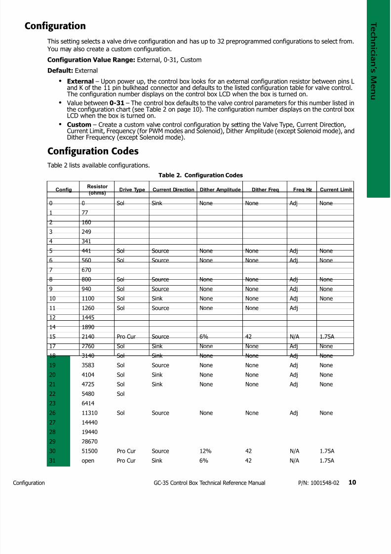
7172019 GC 35 Tecnical Reference Manual
httpslidepdfcomreaderfullgc-35-tecnical-reference-manual 1323
onfiguration 10GC-35 Control Box Technical Reference Manual PN 1001548-02
Configuration
This setting selects a valve drive configuration and has up to 32 preprogrammed configurations to select from You may also create a custom configuration
Configuration Value Range External 0-31 Custom
Default External
bull External ndash Upon power up the control box looks for an external configuration resistor between pins Land K of the 11 pin bulkhead connector and defaults to the listed configuration table for valve control
The configuration number displays on the control box LCD when the box is turned onbull Value between 0-31 ndash The control box defaults to the valve control parameters for this number listed inthe configuration chart (see Table 2 on page 10) The configuration number displays on the control boxLCD when the box is turned on
bull Custom ndash Create a custom valve control configuration by setting the Valve Type Current DirectionCurrent Limit Frequency (for PWM modes and Solenoid) Dither Amplitude (except Solenoid mode) andDither Frequency (except Solenoid mode)
Configuration Codes
Table 2 lists available configurations
Table 2 Configuration Codes
ConfigResistor
(ohms)
Drive Type Current Direction Dither Amplitude Dither Freq Freq Hz Current Limit
0 0 Sol Sink None None Adj None
1 77
2 160
3 249
4 341
5 441 Sol Source None None Adj None
6 560 Sol Source None None Adj None
7 670
8 800 Sol Source None None Adj None
9 940 Sol Source None None Adj None10 1100 Sol Sink None None Adj None
11 1260 Sol Source None None Adj
12 1445
14 1890
15 2140 Pro Cur Source 6 42 NA 175A
17 2760 Sol Sink None None Adj None
18 3140 Sol Sink None None Adj None
19 3583 Sol Source None None Adj None
20 4104 Sol Sink None None Adj None
21 4725 Sol Sink None None Adj None
22 5480 Sol
23 6414
26 11310 Sol Source None None Adj None
27 14440
28 19440
29 28670
30 51500 Pro Cur Source 12 42 NA 175A
31 open Pro Cur Sink 6 42 NA 175A
7172019 GC 35 Tecnical Reference Manual
httpslidepdfcomreaderfullgc-35-tecnical-reference-manual 1423
veraging 11GC-35 Control Box Technical Reference Manual PN 1001548-02
Averaging
Averaging changes the amount of dampening or filtering applied to the laser receiver or elevation sensormeasurements Averaging can be thought of as the time period over which a running average of the elevationmeasurement is calculated
Averaging Value Range 1ndash100
Default 50
A lower value averages fewer elevation measurements allowing the system to react more quickly to grade
changes
A larger value averages more elevation measurements making the system less reactive to fluctuations in gradesuch as with laser ldquobeam bouncerdquo on windy days
Valve Type
Valve Type allows you to select the type of valves used on your machine
Valve Type Value Range Solenoid Servo Proportional Danfoss Pulse PWMDefault Proportional
The following sections describe each of these valve types
Proportional Current
Proportional Current provides a current regulated proportional output and is the preferred setting forproportional valves
A percentage of the total current setting is calculated based on the gain setting and given grade correctionProportional Current control applies full machine voltage to the valve coil until the desired current is reachedthen the voltage is turned off When the current drops below the desired value the process is repeated
Proportional Pulse Width Modulated
Proportional Pulse Width Modulated provides a pulse width regulated proportional output
A percentage of the total duty cycle is calculated based on the gain setting and the given grade correction PulseWidth Modulation cycles the output voltage on and off at the desired duty cycle
Solenoid
Solenoid operates the same as PWM mode except set up specifically for the lower frequency solenoid valves
Danfoss
Danfoss provides a proportional voltage output to drive the specific requirements of the Danfoss brand ofproportional valves In this mode switched power (Vsw) and ground connect to the Danfoss valve through thevalve cable and the Raise output pin of the control box controls the reference signal to the valve In a neutral(no grade) correction output the reference signal is held at half of the switched voltage For example if a 12volt system produced 13 volts on the Vsw line 65 volts are held on the reference output for a no correctionsignal
bull For a raise correction signal the control box increases the reference voltage from 65 to a maximum of975 V
Averaging does not affect slope control
7172019 GC 35 Tecnical Reference Manual
httpslidepdfcomreaderfullgc-35-tecnical-reference-manual 1523
alve Drive 12GC-35 Control Box Technical Reference Manual PN 1001548-02
bull For a lower output signal the control box decreases the reference voltage to a minimum of 325 V
Valve Drive
Valve Drive selects the current direction of the valves on the machine
Valve Drive Value Range Sink Source
Select Sink if the valve has a permanent positive connection and needs a switched negative connection (thecontrol box sinks current)
Select Source if the valve has a permanent ground (negative) connection and needs a switched positiveconnection (the control box sources current)
Dither Amplitude
Dither Amplitude allows you to select the amount of dither to apply to the valve
Dither is a continuous low frequency ldquopulserdquo applied to the valve drive signal for proportional valves to keep thevalversquos spool from sticking
Dither Amplitude Value Range 0ndash15
Dither Amplitude is a percentage of full current for the Proportional Current valve type or duty cycle for thePWM valve type Dither does not apply for Solenoid Danfoss or Servo valve types
Dither Frequency
Dither Frequency adjusts the frequency of the dither in cycles per second
Dither Frequency Value Range 0ndash105 Hz
Frequency
Frequency adjusts the number of pulses sent to control valves in one secondFrequency Value Range 1ndash13 Hz 225ndash1950 Hz
The frequency value is adjustable from 1 to 13 Hz for Solenoid valves On Pulse Width Modulated mode valvesthe range is 225 to 1950 Hz
Max Current
Max Current adjusts the maximum valve drive current that the control box outputs when using ProportionalCurrent valve output mode and the over-current trip level for other valve types
Current Limit Value Range 067ndash48 Amps
If a Danfoss valve sees a reference voltage greater than 75 of Vsw or below 25 of Vsw the valvedefaults to an ldquoerrorrdquo state and the valve is held in the neutral position
Frequency does not apply for Proportional Current and Danfoss valve types
Changing the Frequency has an effect on the Offset Check the Offset after changing theFrequency
7172019 GC 35 Tecnical Reference Manual
httpslidepdfcomreaderfullgc-35-tecnical-reference-manual 1623
our 13GC-35 Control Box Technical Reference Manual PN 1001548-02
Hour
Hour displays the amount of hours the control box has been operating and the amount of hours the control boxhas been operating in Automatic
Hour Settings No settings (read only)
External Auto
External Auto disables or enables an external automanual switch
External Auto Settings OnOffInvert
If On is selected the system requires both an external AM switch and activation of the Control Boxrsquos Autobutton to switch the system in and out of Automatic control Activate the external AM switch by connectingpin E of the 11 PIN bulkhead to ground
If you select Invert connecting pin E to ground takes the system out of Automatic control Automatic controlactivates only when pin E is connected to power such as when connecting to an in-motion switch
Auto Power (Paver Only)
The Auto Power setting allows the system to automatically power up to the last used mode
Auto Power Settings OnOff
When the Auto Power setting is On the system powers up in the last mode seen before power down (Auto orManual) For example the paver is in automatic control is shut down and then powered up once more Thepaver is now ready to pave in Auto
When the Auto Power setting is Off the operator must press the Auto button to return to Auto after a powerdown
Esup2 Reset
Esup2 Reset reconfigures the system to factory settings
Esup2 Reset Settings Range CancelReset
To reset all settings in the Performance Menu and the Technician Menu to factory defaults select Reset and press and hold the Enter button for three (3) seconds
To cancel and return to the previous screen select Cancel
Lock Menu
The Lock-Out Setting allows certain Performance Settings in the Performance Menu to be made inaccessibleto the operator (see ldquoPaver Lock Menu Settingsrdquo on page 14)
If the Auto Power setting is On the machine powers up in Auto any time it was shut down in AutoOnly use Auto Power On in asphalt paver applications
Setting Auto Power to On for a machine other than asphalt pavers is not recommended Seriousinjury to operators or bystanders from unexpected machine movement could result
If you select Reset the Control Box reverts your custom Control Box settings back to their factorydefault values
7172019 GC 35 Tecnical Reference Manual
httpslidepdfcomreaderfullgc-35-tecnical-reference-manual 1723
levation Gains (Raise and Lower) 14GC-35 Control Box Technical Reference Manual PN 1001548-02
Lock-Out Value Range Level 1 - Unlocked Level2 - Moderate Level 3 - Restricted
bull Level 1 ndash all Performance Menu items are accessible to the operator
bull Level 2ndash some items no longer appear in the Performance Menu and are only accessible in theTechnicianrsquos Menu
bull Level 3 ndash additional items no longer appear in the Performance Menu and are only accessible in theTechnicianrsquos Menu
Lock Menu Settings
Table 3 lists the settings that can be locked out (made unavailable)
Elevation Gains (Raise and Lower)
Elevation Gains determines the speed at which your Topcon P-32 System allows the tow point cylinders to adjustto a change in elevation For faster hydraulic response increase the gain value For slower hydraulic responsedecrease the gain value
The objective is to set the gain so the screed reacts to the change in grade quickly but without ldquoovershootingrdquothe new elevation
Gain Elevation Value Range 1-200
Table 3 Paver Lock Menu Settings
Performance Menu Item Level 1 - Unlocked Level 2 - Moderate Level 3 - Restricted
1 Elevation Gains Available Available Locked
2 Slope Gain Available Available Locked
3 Valve Offsets Available Available Locked
4 Elevation Deadband Available Locked Locked
5 Slope Deadband Available Locked Locked
6 Averaging Available Locked Locked
7 Machine Type Available Available Available
8 Display Available Available Available
9 Units Available Available Available
10 System Info Available Available Available
11 Sonic Tracker 3 Available Available Available
12 Slope Resolution Available Available Available
13 Slope Cal Block Available Available Locked
14 Tech Menu Available Available Available
Before setting the Elevation Gain make sure the machines hydraulic flow controls valves are adjustedfor proper cylinder speed according to the manufacturers recommendations
7172019 GC 35 Tecnical Reference Manual
httpslidepdfcomreaderfullgc-35-tecnical-reference-manual 1823
lope Gain 15GC-35 Control Box Technical Reference Manual PN 1001548-02
Slope Gain
This setting determines the speed at which your Topcon P-32 System allows the tow point cylinders to adjustto a change in slope For faster hydraulic response increase the gain value For slower hydraulic responsedecrease the gain value
The objective is to set the gain so the screed reacts to the change in grade quickly but without ldquoovershootingrdquoOn-Grade Slope Gain should not be set at a higher value than the Elevation Gain on the other side of the paver
Gain Elevation Value Range 1-100
Valve Offsets (Raise and Lower)
Valve Offsets is the minimum amount of electrical signals sent to the valve which causes the hydraulic cylinderto move If the valve offset is too small the sensor will not reach On-Grade Likewise if the valve offset valueis too large the sensor will move too much and overshoot On-Grade
Run the Paver until the hydraulic oil is at normal operating temperature before setting the valve offsets Oncethey are set you should not need to readjust the valve offsets unless the Control Box is moved to a new paveror the hydraulic performance changes
Valve Offset Value Range (Raise and Lower) 1 - 999
Elevation Deadband
Elevation Deadband is the area of the Working Window that is On-Grade While the reference is within that areathe paverrsquos valves are idle (closed) Therefore the wider the Elevation Deadband (On-Grade area) the more areference can move up or down without a correction being initiated Once the signal from the reference is outof the deadband your control box drives the hydraulics to place the reference back in the center of thedeadband
Deadband Elevation Value Range 1ndash30 mm
Before setting the Slope Gain ensure the machines hydraulic flow control valves are adjusted forproper cylinder speed according to the manufacturers recommendations
Do not set slope gain at a higher value than the elevation gain on the other side of the paver A highervalue may cause the slope to be over reactive
Set the Valve Offsets before adjusting elevation and slope gains and averaging
The offset value on one side of the paver may differ from the offset value on the other side of thepaver You must verify the offset values before swapping boxes Use the ldquoLeftrdquo and ldquoRightrdquo labelsprovided
Never attempt to use Valve Offsets to compensate for a slower raise or lower speed of your hydraulicvalves as it causes undershooting or overshooting in Slope Mode and can adversely affect the qualityof the mat
Select the amount of Elevation Deadband carefully Too small of an Elevation Deadband causes thetow point cylinder to constantly hunt up and down while the sensor tries to find On-Grade Too largeof an Elevation Deadband does not allow the sensor to send grade corrections to the values causingunwanted variations in mat thickness
7172019 GC 35 Tecnical Reference Manual
httpslidepdfcomreaderfullgc-35-tecnical-reference-manual 1923
lope Deadband 16GC-35 Control Box Technical Reference Manual PN 1001548-02
Slope Deadband
Slope Deadband defines the size of the on-grade area where no valve corrections are made
Deadband Slope Value Range 0025ndash075
The wider the Slope Deadband the greater the slope can vary without initiating a correction
For example if the operator is grading at a 20 slope and the Slope Deadband is set at 10 the system
reads on-grade anywhere from 195 slope to 205 slope The lower the percentage the tighter the SlopeDeadband
Once the slope signal is out of the Slope Deadband System Five drives the hydraulics back within the SlopeDeadband
Working Window Adjustment
Working Window Adjustment adjusts the working window of the sonic tracker (Figure 5)
Working Window Settings 0ndash500 Off
Default 020
The default setting is 020 which gives 020 ft (61 mm) above and below on-grade Setting the value to Offcompletely disables the working window and allows any target to be seen
7172019 GC 35 Tecnical Reference Manual
httpslidepdfcomreaderfullgc-35-tecnical-reference-manual 2023
lope Working Window 17GC-35 Control Box Technical Reference Manual PN 1001548-02
Figure 5 Sonic Tracker Working Window
Slope Working Window
Slope Working Window adjusts the working window of the Slope Sensor (Figure 6)
Slope Working Window Value Range 01 - 100 Off
Default 20
The default setting is 20 which gives 20 slope above and below ongrade Setting the value to Off completelydisables the working window
Out of Range
Ongrade
Flashing UpDown Arrow
Solid UpDown Arrow
20rsquo
20rsquo
20rsquo
20rsquo
Working
Window
(Adjustable)
ST-3 Sonic Tracker II
When using the Sonic Tracker II to follow a stringline curb or other elevated reference there is adanger of making an unwanted cut if the Trackerrsquos sonic cone moves away from the target This canoccur if the working window is either off or set as high as the distance between the reference and theground Setting the working window to the default value of 20 (020ft) prevents the automatic controlfrom making such a reaction due to a loss of the target
7172019 GC 35 Tecnical Reference Manual
httpslidepdfcomreaderfullgc-35-tecnical-reference-manual 2123
martlink (Elevation and Slope) 18GC-35 Control Box Technical Reference Manual PN 1001548-02
Figure 6 Slope Working Window
Smartlink (Elevation and Slope)
Smartlink allows the Control Box to send a percentage of the slopeelevation correction on one side of themachine to the Control Box on the other side of the machine preemptively raising or lowering that hydrauliccylinder to keep the machine at the correct grade Smartlink decreases the lag in correction that can occur onone side of the machine as the second Control Box begins moving the valve without having to wait for thesensor on the other side of the machine to detect and correct for a change in elevationslope
Smartlink Value Range 0 - 100
Default 0
Out of Range
Working Window (Adjustable)
Ongrade
20
20
Ongrade
20
20
7172019 GC 35 Tecnical Reference Manual
httpslidepdfcomreaderfullgc-35-tecnical-reference-manual 2223
Warranty 19GC-35 Control Box Technical Reference Manual PN 1001548-02
bull bull bull bull bull bull
Warranty
Topcon laser and electronic positioning equipment are guaranteed against defective material and workmanshipunder normal use and application consistent with this Manual The equipment is guaranteed for the period indicatedon the warranty card accompanying the product starting from the date that the product is sold to the originalpurchaser by Topconrsquos Authorized Dealers1
During the warranty period Topcon will at its option repair or replace this product at no additional charge Repairparts and replacement products will be furnished on an exchange basis and will be either reconditioned or new Thislimited warranty does not include service to repair damage to the product resulting from an accident disastermisuses abuse or modification of the product
Warranty service may be obtained from an authorized Topcon warranty service dealer If this product is deliveredby mail purchaser agrees to insure the product or assume the risk of loss or damage in transit to prepay shippingcharges to the warranty service location and to use the original shipping container or equivalent A letter shouldaccompany the package furnishing a description of the problem andor defect
The purchaserrsquos sole remedy shall be replacement as provided above In no event shall Topcon be liable for anydamages or other claim including any claim for lost profits lost savings or other incidental or consequential damagesarising out of the use of or inability to use the product
1 The warranty against defects in a Topcon battery charger or cable is 90 days
7172019 GC 35 Tecnical Reference Manual
httpslidepdfcomreaderfullgc-35-tecnical-reference-manual 2323
7172019 GC 35 Tecnical Reference Manual
httpslidepdfcomreaderfullgc-35-tecnical-reference-manual 1623
our 13GC-35 Control Box Technical Reference Manual PN 1001548-02
Hour
Hour displays the amount of hours the control box has been operating and the amount of hours the control boxhas been operating in Automatic
Hour Settings No settings (read only)
External Auto
External Auto disables or enables an external automanual switch
External Auto Settings OnOffInvert
If On is selected the system requires both an external AM switch and activation of the Control Boxrsquos Autobutton to switch the system in and out of Automatic control Activate the external AM switch by connectingpin E of the 11 PIN bulkhead to ground
If you select Invert connecting pin E to ground takes the system out of Automatic control Automatic controlactivates only when pin E is connected to power such as when connecting to an in-motion switch
Auto Power (Paver Only)
The Auto Power setting allows the system to automatically power up to the last used mode
Auto Power Settings OnOff
When the Auto Power setting is On the system powers up in the last mode seen before power down (Auto orManual) For example the paver is in automatic control is shut down and then powered up once more Thepaver is now ready to pave in Auto
When the Auto Power setting is Off the operator must press the Auto button to return to Auto after a powerdown
Esup2 Reset
Esup2 Reset reconfigures the system to factory settings
Esup2 Reset Settings Range CancelReset
To reset all settings in the Performance Menu and the Technician Menu to factory defaults select Reset and press and hold the Enter button for three (3) seconds
To cancel and return to the previous screen select Cancel
Lock Menu
The Lock-Out Setting allows certain Performance Settings in the Performance Menu to be made inaccessibleto the operator (see ldquoPaver Lock Menu Settingsrdquo on page 14)
If the Auto Power setting is On the machine powers up in Auto any time it was shut down in AutoOnly use Auto Power On in asphalt paver applications
Setting Auto Power to On for a machine other than asphalt pavers is not recommended Seriousinjury to operators or bystanders from unexpected machine movement could result
If you select Reset the Control Box reverts your custom Control Box settings back to their factorydefault values
7172019 GC 35 Tecnical Reference Manual
httpslidepdfcomreaderfullgc-35-tecnical-reference-manual 1723
levation Gains (Raise and Lower) 14GC-35 Control Box Technical Reference Manual PN 1001548-02
Lock-Out Value Range Level 1 - Unlocked Level2 - Moderate Level 3 - Restricted
bull Level 1 ndash all Performance Menu items are accessible to the operator
bull Level 2ndash some items no longer appear in the Performance Menu and are only accessible in theTechnicianrsquos Menu
bull Level 3 ndash additional items no longer appear in the Performance Menu and are only accessible in theTechnicianrsquos Menu
Lock Menu Settings
Table 3 lists the settings that can be locked out (made unavailable)
Elevation Gains (Raise and Lower)
Elevation Gains determines the speed at which your Topcon P-32 System allows the tow point cylinders to adjustto a change in elevation For faster hydraulic response increase the gain value For slower hydraulic responsedecrease the gain value
The objective is to set the gain so the screed reacts to the change in grade quickly but without ldquoovershootingrdquothe new elevation
Gain Elevation Value Range 1-200
Table 3 Paver Lock Menu Settings
Performance Menu Item Level 1 - Unlocked Level 2 - Moderate Level 3 - Restricted
1 Elevation Gains Available Available Locked
2 Slope Gain Available Available Locked
3 Valve Offsets Available Available Locked
4 Elevation Deadband Available Locked Locked
5 Slope Deadband Available Locked Locked
6 Averaging Available Locked Locked
7 Machine Type Available Available Available
8 Display Available Available Available
9 Units Available Available Available
10 System Info Available Available Available
11 Sonic Tracker 3 Available Available Available
12 Slope Resolution Available Available Available
13 Slope Cal Block Available Available Locked
14 Tech Menu Available Available Available
Before setting the Elevation Gain make sure the machines hydraulic flow controls valves are adjustedfor proper cylinder speed according to the manufacturers recommendations
7172019 GC 35 Tecnical Reference Manual
httpslidepdfcomreaderfullgc-35-tecnical-reference-manual 1823
lope Gain 15GC-35 Control Box Technical Reference Manual PN 1001548-02
Slope Gain
This setting determines the speed at which your Topcon P-32 System allows the tow point cylinders to adjustto a change in slope For faster hydraulic response increase the gain value For slower hydraulic responsedecrease the gain value
The objective is to set the gain so the screed reacts to the change in grade quickly but without ldquoovershootingrdquoOn-Grade Slope Gain should not be set at a higher value than the Elevation Gain on the other side of the paver
Gain Elevation Value Range 1-100
Valve Offsets (Raise and Lower)
Valve Offsets is the minimum amount of electrical signals sent to the valve which causes the hydraulic cylinderto move If the valve offset is too small the sensor will not reach On-Grade Likewise if the valve offset valueis too large the sensor will move too much and overshoot On-Grade
Run the Paver until the hydraulic oil is at normal operating temperature before setting the valve offsets Oncethey are set you should not need to readjust the valve offsets unless the Control Box is moved to a new paveror the hydraulic performance changes
Valve Offset Value Range (Raise and Lower) 1 - 999
Elevation Deadband
Elevation Deadband is the area of the Working Window that is On-Grade While the reference is within that areathe paverrsquos valves are idle (closed) Therefore the wider the Elevation Deadband (On-Grade area) the more areference can move up or down without a correction being initiated Once the signal from the reference is outof the deadband your control box drives the hydraulics to place the reference back in the center of thedeadband
Deadband Elevation Value Range 1ndash30 mm
Before setting the Slope Gain ensure the machines hydraulic flow control valves are adjusted forproper cylinder speed according to the manufacturers recommendations
Do not set slope gain at a higher value than the elevation gain on the other side of the paver A highervalue may cause the slope to be over reactive
Set the Valve Offsets before adjusting elevation and slope gains and averaging
The offset value on one side of the paver may differ from the offset value on the other side of thepaver You must verify the offset values before swapping boxes Use the ldquoLeftrdquo and ldquoRightrdquo labelsprovided
Never attempt to use Valve Offsets to compensate for a slower raise or lower speed of your hydraulicvalves as it causes undershooting or overshooting in Slope Mode and can adversely affect the qualityof the mat
Select the amount of Elevation Deadband carefully Too small of an Elevation Deadband causes thetow point cylinder to constantly hunt up and down while the sensor tries to find On-Grade Too largeof an Elevation Deadband does not allow the sensor to send grade corrections to the values causingunwanted variations in mat thickness
7172019 GC 35 Tecnical Reference Manual
httpslidepdfcomreaderfullgc-35-tecnical-reference-manual 1923
lope Deadband 16GC-35 Control Box Technical Reference Manual PN 1001548-02
Slope Deadband
Slope Deadband defines the size of the on-grade area where no valve corrections are made
Deadband Slope Value Range 0025ndash075
The wider the Slope Deadband the greater the slope can vary without initiating a correction
For example if the operator is grading at a 20 slope and the Slope Deadband is set at 10 the system
reads on-grade anywhere from 195 slope to 205 slope The lower the percentage the tighter the SlopeDeadband
Once the slope signal is out of the Slope Deadband System Five drives the hydraulics back within the SlopeDeadband
Working Window Adjustment
Working Window Adjustment adjusts the working window of the sonic tracker (Figure 5)
Working Window Settings 0ndash500 Off
Default 020
The default setting is 020 which gives 020 ft (61 mm) above and below on-grade Setting the value to Offcompletely disables the working window and allows any target to be seen
7172019 GC 35 Tecnical Reference Manual
httpslidepdfcomreaderfullgc-35-tecnical-reference-manual 2023
lope Working Window 17GC-35 Control Box Technical Reference Manual PN 1001548-02
Figure 5 Sonic Tracker Working Window
Slope Working Window
Slope Working Window adjusts the working window of the Slope Sensor (Figure 6)
Slope Working Window Value Range 01 - 100 Off
Default 20
The default setting is 20 which gives 20 slope above and below ongrade Setting the value to Off completelydisables the working window
Out of Range
Ongrade
Flashing UpDown Arrow
Solid UpDown Arrow
20rsquo
20rsquo
20rsquo
20rsquo
Working
Window
(Adjustable)
ST-3 Sonic Tracker II
When using the Sonic Tracker II to follow a stringline curb or other elevated reference there is adanger of making an unwanted cut if the Trackerrsquos sonic cone moves away from the target This canoccur if the working window is either off or set as high as the distance between the reference and theground Setting the working window to the default value of 20 (020ft) prevents the automatic controlfrom making such a reaction due to a loss of the target
7172019 GC 35 Tecnical Reference Manual
httpslidepdfcomreaderfullgc-35-tecnical-reference-manual 2123
martlink (Elevation and Slope) 18GC-35 Control Box Technical Reference Manual PN 1001548-02
Figure 6 Slope Working Window
Smartlink (Elevation and Slope)
Smartlink allows the Control Box to send a percentage of the slopeelevation correction on one side of themachine to the Control Box on the other side of the machine preemptively raising or lowering that hydrauliccylinder to keep the machine at the correct grade Smartlink decreases the lag in correction that can occur onone side of the machine as the second Control Box begins moving the valve without having to wait for thesensor on the other side of the machine to detect and correct for a change in elevationslope
Smartlink Value Range 0 - 100
Default 0
Out of Range
Working Window (Adjustable)
Ongrade
20
20
Ongrade
20
20
7172019 GC 35 Tecnical Reference Manual
httpslidepdfcomreaderfullgc-35-tecnical-reference-manual 2223
Warranty 19GC-35 Control Box Technical Reference Manual PN 1001548-02
bull bull bull bull bull bull
Warranty
Topcon laser and electronic positioning equipment are guaranteed against defective material and workmanshipunder normal use and application consistent with this Manual The equipment is guaranteed for the period indicatedon the warranty card accompanying the product starting from the date that the product is sold to the originalpurchaser by Topconrsquos Authorized Dealers1
During the warranty period Topcon will at its option repair or replace this product at no additional charge Repairparts and replacement products will be furnished on an exchange basis and will be either reconditioned or new Thislimited warranty does not include service to repair damage to the product resulting from an accident disastermisuses abuse or modification of the product
Warranty service may be obtained from an authorized Topcon warranty service dealer If this product is deliveredby mail purchaser agrees to insure the product or assume the risk of loss or damage in transit to prepay shippingcharges to the warranty service location and to use the original shipping container or equivalent A letter shouldaccompany the package furnishing a description of the problem andor defect
The purchaserrsquos sole remedy shall be replacement as provided above In no event shall Topcon be liable for anydamages or other claim including any claim for lost profits lost savings or other incidental or consequential damagesarising out of the use of or inability to use the product
1 The warranty against defects in a Topcon battery charger or cable is 90 days
7172019 GC 35 Tecnical Reference Manual
httpslidepdfcomreaderfullgc-35-tecnical-reference-manual 2323
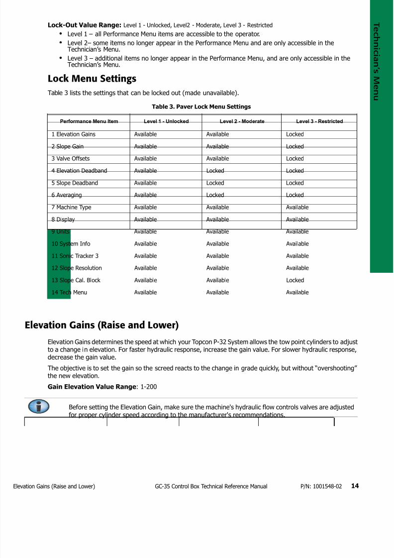
7172019 GC 35 Tecnical Reference Manual
httpslidepdfcomreaderfullgc-35-tecnical-reference-manual 1723
levation Gains (Raise and Lower) 14GC-35 Control Box Technical Reference Manual PN 1001548-02
Lock-Out Value Range Level 1 - Unlocked Level2 - Moderate Level 3 - Restricted
bull Level 1 ndash all Performance Menu items are accessible to the operator
bull Level 2ndash some items no longer appear in the Performance Menu and are only accessible in theTechnicianrsquos Menu
bull Level 3 ndash additional items no longer appear in the Performance Menu and are only accessible in theTechnicianrsquos Menu
Lock Menu Settings
Table 3 lists the settings that can be locked out (made unavailable)
Elevation Gains (Raise and Lower)
Elevation Gains determines the speed at which your Topcon P-32 System allows the tow point cylinders to adjustto a change in elevation For faster hydraulic response increase the gain value For slower hydraulic responsedecrease the gain value
The objective is to set the gain so the screed reacts to the change in grade quickly but without ldquoovershootingrdquothe new elevation
Gain Elevation Value Range 1-200
Table 3 Paver Lock Menu Settings
Performance Menu Item Level 1 - Unlocked Level 2 - Moderate Level 3 - Restricted
1 Elevation Gains Available Available Locked
2 Slope Gain Available Available Locked
3 Valve Offsets Available Available Locked
4 Elevation Deadband Available Locked Locked
5 Slope Deadband Available Locked Locked
6 Averaging Available Locked Locked
7 Machine Type Available Available Available
8 Display Available Available Available
9 Units Available Available Available
10 System Info Available Available Available
11 Sonic Tracker 3 Available Available Available
12 Slope Resolution Available Available Available
13 Slope Cal Block Available Available Locked
14 Tech Menu Available Available Available
Before setting the Elevation Gain make sure the machines hydraulic flow controls valves are adjustedfor proper cylinder speed according to the manufacturers recommendations
7172019 GC 35 Tecnical Reference Manual
httpslidepdfcomreaderfullgc-35-tecnical-reference-manual 1823
lope Gain 15GC-35 Control Box Technical Reference Manual PN 1001548-02
Slope Gain
This setting determines the speed at which your Topcon P-32 System allows the tow point cylinders to adjustto a change in slope For faster hydraulic response increase the gain value For slower hydraulic responsedecrease the gain value
The objective is to set the gain so the screed reacts to the change in grade quickly but without ldquoovershootingrdquoOn-Grade Slope Gain should not be set at a higher value than the Elevation Gain on the other side of the paver
Gain Elevation Value Range 1-100
Valve Offsets (Raise and Lower)
Valve Offsets is the minimum amount of electrical signals sent to the valve which causes the hydraulic cylinderto move If the valve offset is too small the sensor will not reach On-Grade Likewise if the valve offset valueis too large the sensor will move too much and overshoot On-Grade
Run the Paver until the hydraulic oil is at normal operating temperature before setting the valve offsets Oncethey are set you should not need to readjust the valve offsets unless the Control Box is moved to a new paveror the hydraulic performance changes
Valve Offset Value Range (Raise and Lower) 1 - 999
Elevation Deadband
Elevation Deadband is the area of the Working Window that is On-Grade While the reference is within that areathe paverrsquos valves are idle (closed) Therefore the wider the Elevation Deadband (On-Grade area) the more areference can move up or down without a correction being initiated Once the signal from the reference is outof the deadband your control box drives the hydraulics to place the reference back in the center of thedeadband
Deadband Elevation Value Range 1ndash30 mm
Before setting the Slope Gain ensure the machines hydraulic flow control valves are adjusted forproper cylinder speed according to the manufacturers recommendations
Do not set slope gain at a higher value than the elevation gain on the other side of the paver A highervalue may cause the slope to be over reactive
Set the Valve Offsets before adjusting elevation and slope gains and averaging
The offset value on one side of the paver may differ from the offset value on the other side of thepaver You must verify the offset values before swapping boxes Use the ldquoLeftrdquo and ldquoRightrdquo labelsprovided
Never attempt to use Valve Offsets to compensate for a slower raise or lower speed of your hydraulicvalves as it causes undershooting or overshooting in Slope Mode and can adversely affect the qualityof the mat
Select the amount of Elevation Deadband carefully Too small of an Elevation Deadband causes thetow point cylinder to constantly hunt up and down while the sensor tries to find On-Grade Too largeof an Elevation Deadband does not allow the sensor to send grade corrections to the values causingunwanted variations in mat thickness
7172019 GC 35 Tecnical Reference Manual
httpslidepdfcomreaderfullgc-35-tecnical-reference-manual 1923
lope Deadband 16GC-35 Control Box Technical Reference Manual PN 1001548-02
Slope Deadband
Slope Deadband defines the size of the on-grade area where no valve corrections are made
Deadband Slope Value Range 0025ndash075
The wider the Slope Deadband the greater the slope can vary without initiating a correction
For example if the operator is grading at a 20 slope and the Slope Deadband is set at 10 the system
reads on-grade anywhere from 195 slope to 205 slope The lower the percentage the tighter the SlopeDeadband
Once the slope signal is out of the Slope Deadband System Five drives the hydraulics back within the SlopeDeadband
Working Window Adjustment
Working Window Adjustment adjusts the working window of the sonic tracker (Figure 5)
Working Window Settings 0ndash500 Off
Default 020
The default setting is 020 which gives 020 ft (61 mm) above and below on-grade Setting the value to Offcompletely disables the working window and allows any target to be seen
7172019 GC 35 Tecnical Reference Manual
httpslidepdfcomreaderfullgc-35-tecnical-reference-manual 2023
lope Working Window 17GC-35 Control Box Technical Reference Manual PN 1001548-02
Figure 5 Sonic Tracker Working Window
Slope Working Window
Slope Working Window adjusts the working window of the Slope Sensor (Figure 6)
Slope Working Window Value Range 01 - 100 Off
Default 20
The default setting is 20 which gives 20 slope above and below ongrade Setting the value to Off completelydisables the working window
Out of Range
Ongrade
Flashing UpDown Arrow
Solid UpDown Arrow
20rsquo
20rsquo
20rsquo
20rsquo
Working
Window
(Adjustable)
ST-3 Sonic Tracker II
When using the Sonic Tracker II to follow a stringline curb or other elevated reference there is adanger of making an unwanted cut if the Trackerrsquos sonic cone moves away from the target This canoccur if the working window is either off or set as high as the distance between the reference and theground Setting the working window to the default value of 20 (020ft) prevents the automatic controlfrom making such a reaction due to a loss of the target
7172019 GC 35 Tecnical Reference Manual
httpslidepdfcomreaderfullgc-35-tecnical-reference-manual 2123
martlink (Elevation and Slope) 18GC-35 Control Box Technical Reference Manual PN 1001548-02
Figure 6 Slope Working Window
Smartlink (Elevation and Slope)
Smartlink allows the Control Box to send a percentage of the slopeelevation correction on one side of themachine to the Control Box on the other side of the machine preemptively raising or lowering that hydrauliccylinder to keep the machine at the correct grade Smartlink decreases the lag in correction that can occur onone side of the machine as the second Control Box begins moving the valve without having to wait for thesensor on the other side of the machine to detect and correct for a change in elevationslope
Smartlink Value Range 0 - 100
Default 0
Out of Range
Working Window (Adjustable)
Ongrade
20
20
Ongrade
20
20
7172019 GC 35 Tecnical Reference Manual
httpslidepdfcomreaderfullgc-35-tecnical-reference-manual 2223
Warranty 19GC-35 Control Box Technical Reference Manual PN 1001548-02
bull bull bull bull bull bull
Warranty
Topcon laser and electronic positioning equipment are guaranteed against defective material and workmanshipunder normal use and application consistent with this Manual The equipment is guaranteed for the period indicatedon the warranty card accompanying the product starting from the date that the product is sold to the originalpurchaser by Topconrsquos Authorized Dealers1
During the warranty period Topcon will at its option repair or replace this product at no additional charge Repairparts and replacement products will be furnished on an exchange basis and will be either reconditioned or new Thislimited warranty does not include service to repair damage to the product resulting from an accident disastermisuses abuse or modification of the product
Warranty service may be obtained from an authorized Topcon warranty service dealer If this product is deliveredby mail purchaser agrees to insure the product or assume the risk of loss or damage in transit to prepay shippingcharges to the warranty service location and to use the original shipping container or equivalent A letter shouldaccompany the package furnishing a description of the problem andor defect
The purchaserrsquos sole remedy shall be replacement as provided above In no event shall Topcon be liable for anydamages or other claim including any claim for lost profits lost savings or other incidental or consequential damagesarising out of the use of or inability to use the product
1 The warranty against defects in a Topcon battery charger or cable is 90 days
7172019 GC 35 Tecnical Reference Manual
httpslidepdfcomreaderfullgc-35-tecnical-reference-manual 2323
7172019 GC 35 Tecnical Reference Manual
httpslidepdfcomreaderfullgc-35-tecnical-reference-manual 1923
lope Deadband 16GC-35 Control Box Technical Reference Manual PN 1001548-02
Slope Deadband
Slope Deadband defines the size of the on-grade area where no valve corrections are made
Deadband Slope Value Range 0025ndash075
The wider the Slope Deadband the greater the slope can vary without initiating a correction
For example if the operator is grading at a 20 slope and the Slope Deadband is set at 10 the system
reads on-grade anywhere from 195 slope to 205 slope The lower the percentage the tighter the SlopeDeadband
Once the slope signal is out of the Slope Deadband System Five drives the hydraulics back within the SlopeDeadband
Working Window Adjustment
Working Window Adjustment adjusts the working window of the sonic tracker (Figure 5)
Working Window Settings 0ndash500 Off
Default 020
The default setting is 020 which gives 020 ft (61 mm) above and below on-grade Setting the value to Offcompletely disables the working window and allows any target to be seen
7172019 GC 35 Tecnical Reference Manual
httpslidepdfcomreaderfullgc-35-tecnical-reference-manual 2023
lope Working Window 17GC-35 Control Box Technical Reference Manual PN 1001548-02
Figure 5 Sonic Tracker Working Window
Slope Working Window
Slope Working Window adjusts the working window of the Slope Sensor (Figure 6)
Slope Working Window Value Range 01 - 100 Off
Default 20
The default setting is 20 which gives 20 slope above and below ongrade Setting the value to Off completelydisables the working window
Out of Range
Ongrade
Flashing UpDown Arrow
Solid UpDown Arrow
20rsquo
20rsquo
20rsquo
20rsquo
Working
Window
(Adjustable)
ST-3 Sonic Tracker II
When using the Sonic Tracker II to follow a stringline curb or other elevated reference there is adanger of making an unwanted cut if the Trackerrsquos sonic cone moves away from the target This canoccur if the working window is either off or set as high as the distance between the reference and theground Setting the working window to the default value of 20 (020ft) prevents the automatic controlfrom making such a reaction due to a loss of the target
7172019 GC 35 Tecnical Reference Manual
httpslidepdfcomreaderfullgc-35-tecnical-reference-manual 2123
martlink (Elevation and Slope) 18GC-35 Control Box Technical Reference Manual PN 1001548-02
Figure 6 Slope Working Window
Smartlink (Elevation and Slope)
Smartlink allows the Control Box to send a percentage of the slopeelevation correction on one side of themachine to the Control Box on the other side of the machine preemptively raising or lowering that hydrauliccylinder to keep the machine at the correct grade Smartlink decreases the lag in correction that can occur onone side of the machine as the second Control Box begins moving the valve without having to wait for thesensor on the other side of the machine to detect and correct for a change in elevationslope
Smartlink Value Range 0 - 100
Default 0
Out of Range
Working Window (Adjustable)
Ongrade
20
20
Ongrade
20
20
7172019 GC 35 Tecnical Reference Manual
httpslidepdfcomreaderfullgc-35-tecnical-reference-manual 2223
Warranty 19GC-35 Control Box Technical Reference Manual PN 1001548-02
bull bull bull bull bull bull
Warranty
Topcon laser and electronic positioning equipment are guaranteed against defective material and workmanshipunder normal use and application consistent with this Manual The equipment is guaranteed for the period indicatedon the warranty card accompanying the product starting from the date that the product is sold to the originalpurchaser by Topconrsquos Authorized Dealers1
During the warranty period Topcon will at its option repair or replace this product at no additional charge Repairparts and replacement products will be furnished on an exchange basis and will be either reconditioned or new Thislimited warranty does not include service to repair damage to the product resulting from an accident disastermisuses abuse or modification of the product
Warranty service may be obtained from an authorized Topcon warranty service dealer If this product is deliveredby mail purchaser agrees to insure the product or assume the risk of loss or damage in transit to prepay shippingcharges to the warranty service location and to use the original shipping container or equivalent A letter shouldaccompany the package furnishing a description of the problem andor defect
The purchaserrsquos sole remedy shall be replacement as provided above In no event shall Topcon be liable for anydamages or other claim including any claim for lost profits lost savings or other incidental or consequential damagesarising out of the use of or inability to use the product
1 The warranty against defects in a Topcon battery charger or cable is 90 days
7172019 GC 35 Tecnical Reference Manual
httpslidepdfcomreaderfullgc-35-tecnical-reference-manual 2323
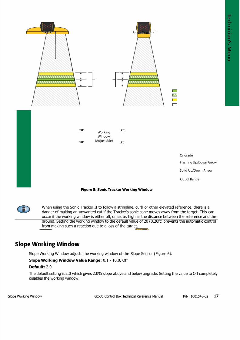
7172019 GC 35 Tecnical Reference Manual
httpslidepdfcomreaderfullgc-35-tecnical-reference-manual 2023
lope Working Window 17GC-35 Control Box Technical Reference Manual PN 1001548-02
Figure 5 Sonic Tracker Working Window
Slope Working Window
Slope Working Window adjusts the working window of the Slope Sensor (Figure 6)
Slope Working Window Value Range 01 - 100 Off
Default 20
The default setting is 20 which gives 20 slope above and below ongrade Setting the value to Off completelydisables the working window
Out of Range
Ongrade
Flashing UpDown Arrow
Solid UpDown Arrow
20rsquo
20rsquo
20rsquo
20rsquo
Working
Window
(Adjustable)
ST-3 Sonic Tracker II
When using the Sonic Tracker II to follow a stringline curb or other elevated reference there is adanger of making an unwanted cut if the Trackerrsquos sonic cone moves away from the target This canoccur if the working window is either off or set as high as the distance between the reference and theground Setting the working window to the default value of 20 (020ft) prevents the automatic controlfrom making such a reaction due to a loss of the target
7172019 GC 35 Tecnical Reference Manual
httpslidepdfcomreaderfullgc-35-tecnical-reference-manual 2123
martlink (Elevation and Slope) 18GC-35 Control Box Technical Reference Manual PN 1001548-02
Figure 6 Slope Working Window
Smartlink (Elevation and Slope)
Smartlink allows the Control Box to send a percentage of the slopeelevation correction on one side of themachine to the Control Box on the other side of the machine preemptively raising or lowering that hydrauliccylinder to keep the machine at the correct grade Smartlink decreases the lag in correction that can occur onone side of the machine as the second Control Box begins moving the valve without having to wait for thesensor on the other side of the machine to detect and correct for a change in elevationslope
Smartlink Value Range 0 - 100
Default 0
Out of Range
Working Window (Adjustable)
Ongrade
20
20
Ongrade
20
20
7172019 GC 35 Tecnical Reference Manual
httpslidepdfcomreaderfullgc-35-tecnical-reference-manual 2223
Warranty 19GC-35 Control Box Technical Reference Manual PN 1001548-02
bull bull bull bull bull bull
Warranty
Topcon laser and electronic positioning equipment are guaranteed against defective material and workmanshipunder normal use and application consistent with this Manual The equipment is guaranteed for the period indicatedon the warranty card accompanying the product starting from the date that the product is sold to the originalpurchaser by Topconrsquos Authorized Dealers1
During the warranty period Topcon will at its option repair or replace this product at no additional charge Repairparts and replacement products will be furnished on an exchange basis and will be either reconditioned or new Thislimited warranty does not include service to repair damage to the product resulting from an accident disastermisuses abuse or modification of the product
Warranty service may be obtained from an authorized Topcon warranty service dealer If this product is deliveredby mail purchaser agrees to insure the product or assume the risk of loss or damage in transit to prepay shippingcharges to the warranty service location and to use the original shipping container or equivalent A letter shouldaccompany the package furnishing a description of the problem andor defect
The purchaserrsquos sole remedy shall be replacement as provided above In no event shall Topcon be liable for anydamages or other claim including any claim for lost profits lost savings or other incidental or consequential damagesarising out of the use of or inability to use the product
1 The warranty against defects in a Topcon battery charger or cable is 90 days
7172019 GC 35 Tecnical Reference Manual
httpslidepdfcomreaderfullgc-35-tecnical-reference-manual 2323
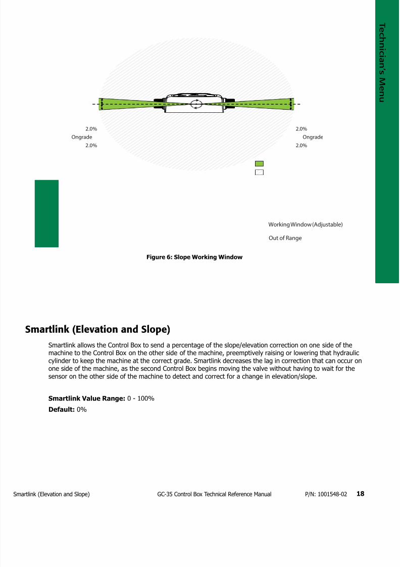
7172019 GC 35 Tecnical Reference Manual
httpslidepdfcomreaderfullgc-35-tecnical-reference-manual 2123
martlink (Elevation and Slope) 18GC-35 Control Box Technical Reference Manual PN 1001548-02
Figure 6 Slope Working Window
Smartlink (Elevation and Slope)
Smartlink allows the Control Box to send a percentage of the slopeelevation correction on one side of themachine to the Control Box on the other side of the machine preemptively raising or lowering that hydrauliccylinder to keep the machine at the correct grade Smartlink decreases the lag in correction that can occur onone side of the machine as the second Control Box begins moving the valve without having to wait for thesensor on the other side of the machine to detect and correct for a change in elevationslope
Smartlink Value Range 0 - 100
Default 0
Out of Range
Working Window (Adjustable)
Ongrade
20
20
Ongrade
20
20
7172019 GC 35 Tecnical Reference Manual
httpslidepdfcomreaderfullgc-35-tecnical-reference-manual 2223
Warranty 19GC-35 Control Box Technical Reference Manual PN 1001548-02
bull bull bull bull bull bull
Warranty
Topcon laser and electronic positioning equipment are guaranteed against defective material and workmanshipunder normal use and application consistent with this Manual The equipment is guaranteed for the period indicatedon the warranty card accompanying the product starting from the date that the product is sold to the originalpurchaser by Topconrsquos Authorized Dealers1
During the warranty period Topcon will at its option repair or replace this product at no additional charge Repairparts and replacement products will be furnished on an exchange basis and will be either reconditioned or new Thislimited warranty does not include service to repair damage to the product resulting from an accident disastermisuses abuse or modification of the product
Warranty service may be obtained from an authorized Topcon warranty service dealer If this product is deliveredby mail purchaser agrees to insure the product or assume the risk of loss or damage in transit to prepay shippingcharges to the warranty service location and to use the original shipping container or equivalent A letter shouldaccompany the package furnishing a description of the problem andor defect
The purchaserrsquos sole remedy shall be replacement as provided above In no event shall Topcon be liable for anydamages or other claim including any claim for lost profits lost savings or other incidental or consequential damagesarising out of the use of or inability to use the product
1 The warranty against defects in a Topcon battery charger or cable is 90 days
7172019 GC 35 Tecnical Reference Manual
httpslidepdfcomreaderfullgc-35-tecnical-reference-manual 2323
7172019 GC 35 Tecnical Reference Manual
httpslidepdfcomreaderfullgc-35-tecnical-reference-manual 2323