gba st1 operation manual - iniciativas murcia · gba global bill acceptors gba st1 operation manual...
TRANSCRIPT
GBA Global Bill Acceptors GBA ST1 Operation Manual
Page 1 of 25 Astrosys International Ltd
November 2005 GBA ST1 Op Manual V1.00
GBA ST1 Operation Manual
This document is the copyright of Astrosys International Ltd. and may not be reproduced in total or in part by
any means, electronic or otherwise, without the prior written consent of Astrosys International Ltd.
GBA Global Bill Acceptors GBA ST1 Operation Manual
Page 2 of 25 Astrosys International Ltd
November 2005 GBA ST1 Op Manual V1.00
Contents
1.0 INTRODUCTION 3
2.0 PRODUCT INFORMATION 4
2.1 General Specifications 4
2.2 Product Architecture 4
2.3 Build Options 5
3.0 MECHANICAL CONFIGURATION 7
3.1 Up stacker / Down stacker Configuration 7
3.2 Cassette Options 8
4.0 INTERFACE PROTOCOLS 10
5.0 SOFTWARE CONFIGURATION 11
5.1 Using On-board Push-Button 11
5.2 Using PC-based GBATools 13
5.3 Software Configuration Options 13
6.0 MECHANICAL INSTALLATION 14
7.0 ELECTRICAL INTERFACE SPECIFICATION 15
8.0 ELECTRICAL CONNECTIONS 16
9.0 MAINTENANCE 18
9.1 Cleaning the Validator Note Path 18
9.2 Clearing a Note Jam 18
9.3 Replacing Drive Belts 19
10.0 DIAGNOSTICS & TROUBLESHOOTING 20
10.1 Diagnostics 20
10.2 Troubleshooting 22
10.3 Dimensional drawings, Up stacker 23
10.4 Dimensional drawings, Down stacker 24
Disclaimer and Warranty 25
Revision History 25
REGIONAL OFFICES 25
GBA Global Bill Acceptors GBA ST1 Operation Manual
Page 3 of 25 Astrosys International Ltd
November 2005 GBA ST1 Op Manual V1.00
1.0 INTRODUCTION
This manual describes the operation and maintenance of the GBA ST1 integrated bill validator and stacker. It is intended to assist the user in the set-up, installation and operation of the product. If you have any questions about this or any other Astrosys products then please visit our web sites at www.globalbillacceptors.com and www.microcoin.com, or contact your regional sales office for assistance. The GBA ST1 has been specifically designed for use in Vending applications, however it can also be used in all applications previously served by the GBA vertical stacker range, including Amusement, Parking and Internet Kiosks. The following features are also offered:
• Up or Down stacking configuration • All new “Sense Technology” note discrimination • Up to 32 different notes accepted with 4 way insertion • Accepts note sizes from 62 to 80mm wide, 120 to 160mm long • Single note escrow • Multiple Cassette note capacity options • Tamper-evident, lockable cassette options • Multiple faceplate options • Optional Flashing note guide • Integral anti-string protection • Supports multiple interfaces • Commercial “plug pack” power supplies supported • On board Individual note enable / disable • Automatic sensor calibration • On board tri-colour diagnostic LED • Easy access to note path for cleaning and servicing • User Support Tools • CE, UL, C-Tick and ROHS compliant • Manufactured to ISO 9001 standards
Please note that the words “bill” and “note” are used interchangeably in this document to imply a single piece of paper currency.
GBA Global Bill Acceptors GBA ST1 Operation Manual
Page 4 of 25 Astrosys International Ltd
November 2005 GBA ST1 Op Manual V1.00
2.0 PRODUCT INFORMATION
2.1 General Specifications Bill Insertion: Up to 32 bill denominations with 4 way insertion Bill Dimensions: 62 to 80mm wide; 120 to 160 mm long Bill Acceptance Rate: Greater than 95% Cycle Time for Validation and Stack: 3 seconds Interface Protocols Supported: Pulse, Parallel, cctalk® (plain & encrypted), bi-direction
serial (“RS232”), NAMA MDB Power Supply: 12Vdc +/-10% (Note: Tip negative for the DC power
supply jack) Power Consumption (Validating): 800mA @ 12V
(Stacking): 700mA @ 12V (Idle): 200mA @ 12V
Environmental Range (Operating Temp): 0° to 55°C (Operating Hum): Up to 90% R.H., non-condensing (Storage Temp): -10° to 65°C
2.2 Product Architecture
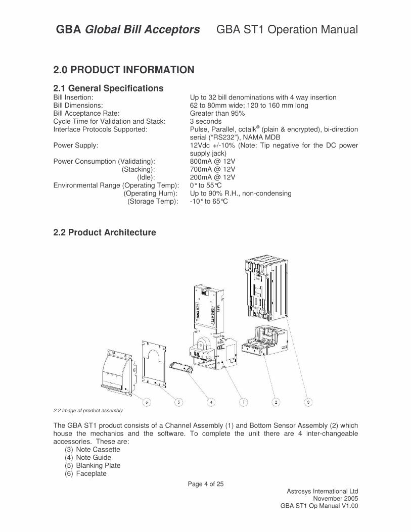
2.2 Image of product assembly The GBA ST1 product consists of a Channel Assembly (1) and Bottom Sensor Assembly (2) which house the mechanics and the software. To complete the unit there are 4 inter-changeable accessories. These are:
(3) Note Cassette (4) Note Guide (5) Blanking Plate (6) Faceplate
GBA Global Bill Acceptors GBA ST1 Operation Manual
Page 5 of 25 Astrosys International Ltd
November 2005 GBA ST1 Op Manual V1.00
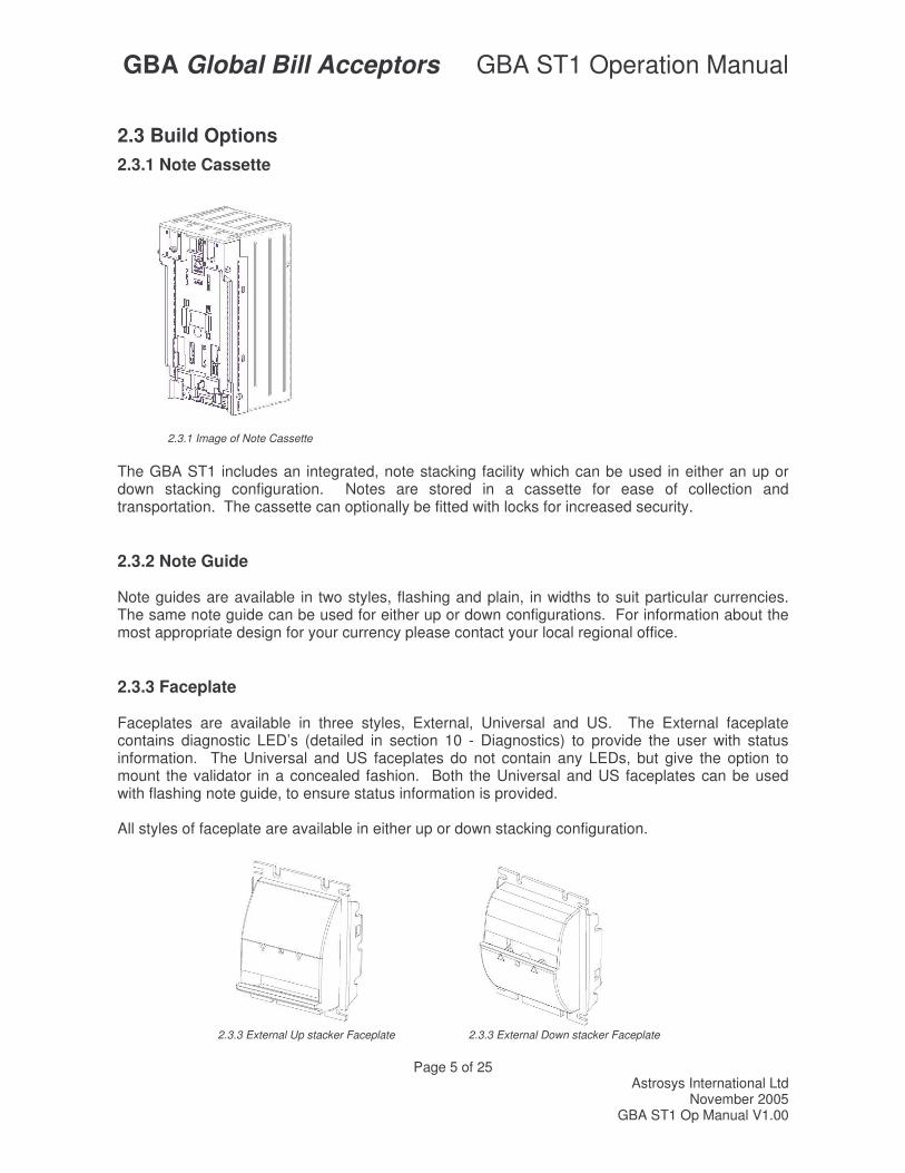
2.3 Build Options 2.3.1 Note Cassette
2.3.1 Image of Note Cassette
The GBA ST1 includes an integrated, note stacking facility which can be used in either an up or down stacking configuration. Notes are stored in a cassette for ease of collection and transportation. The cassette can optionally be fitted with locks for increased security.
2.3.2 Note Guide Note guides are available in two styles, flashing and plain, in widths to suit particular currencies. The same note guide can be used for either up or down configurations. For information about the most appropriate design for your currency please contact your local regional office.
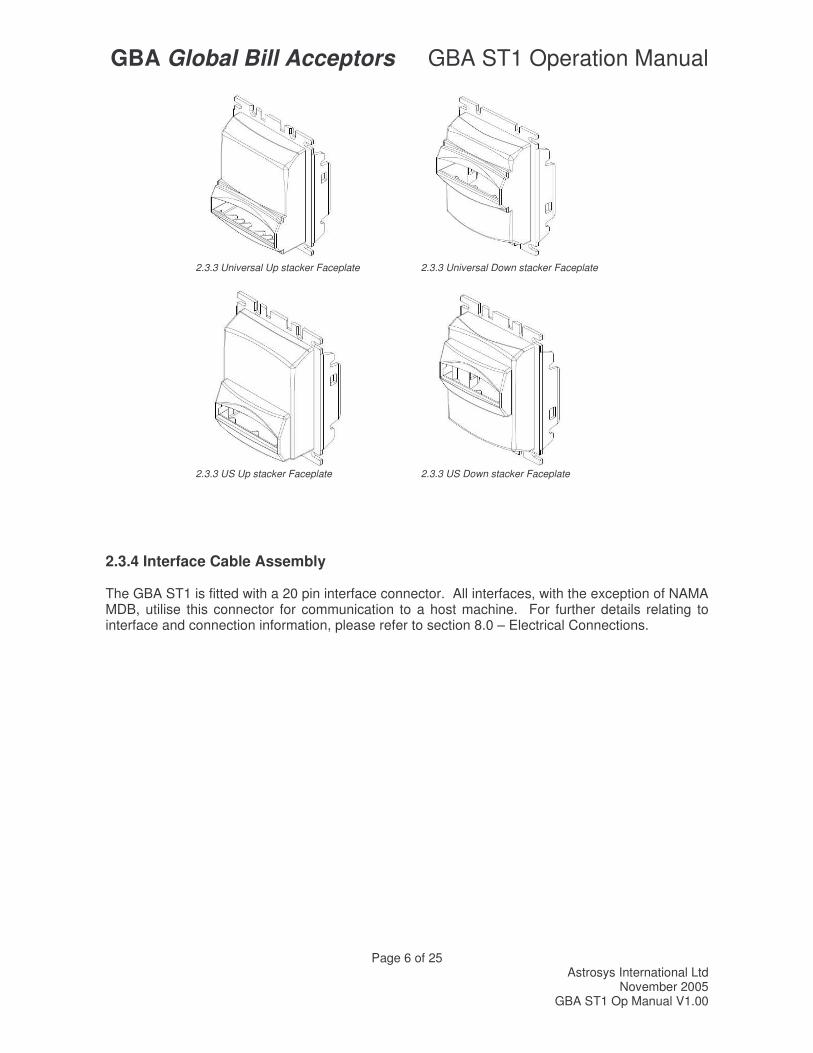
2.3.3 Faceplate Faceplates are available in three styles, External, Universal and US. The External faceplate contains diagnostic LED’s (detailed in section 10 - Diagnostics) to provide the user with status information. The Universal and US faceplates do not contain any LEDs, but give the option to mount the validator in a concealed fashion. Both the Universal and US faceplates can be used with flashing note guide, to ensure status information is provided. All styles of faceplate are available in either up or down stacking configuration.
2.3.3 External Up stacker Faceplate 2.3.3 External Down stacker Faceplate
GBA Global Bill Acceptors GBA ST1 Operation Manual
Page 6 of 25 Astrosys International Ltd
November 2005 GBA ST1 Op Manual V1.00
2.3.3 Universal Up stacker Faceplate 2.3.3 Universal Down stacker Faceplate
2.3.3 US Up stacker Faceplate 2.3.3 US Down stacker Faceplate
2.3.4 Interface Cable Assembly The GBA ST1 is fitted with a 20 pin interface connector. All interfaces, with the exception of NAMA MDB, utilise this connector for communication to a host machine. For further details relating to interface and connection information, please refer to section 8.0 – Electrical Connections.
GBA Global Bill Acceptors GBA ST1 Operation Manual
Page 7 of 25 Astrosys International Ltd
November 2005 GBA ST1 Op Manual V1.00
3.0 MECHANICAL CONFIGURATION
3.1 Up stacker / Down stacker Configuration The GBA ST1 product can be configured for installation in either up or down stacking applications.
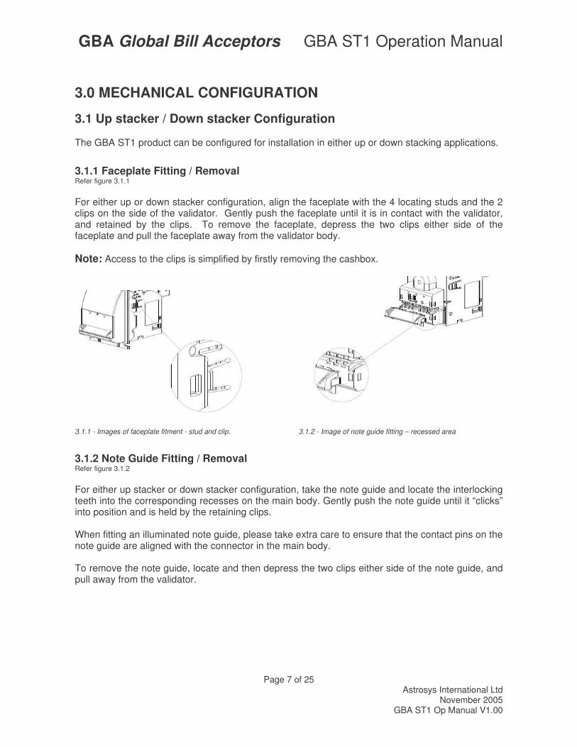
3.1.1 Faceplate Fitting / Removal Refer figure 3.1.1 For either up or down stacker configuration, align the faceplate with the 4 locating studs and the 2 clips on the side of the validator. Gently push the faceplate until it is in contact with the validator, and retained by the clips. To remove the faceplate, depress the two clips either side of the faceplate and pull the faceplate away from the validator body. Note: Access to the clips is simplified by firstly removing the cashbox.
3.1.1 - Images of faceplate fitment - stud and clip. 3.1.2 - Image of note guide fitting – recessed area
3.1.2 Note Guide Fitting / Removal Refer figure 3.1.2 For either up stacker or down stacker configuration, take the note guide and locate the interlocking teeth into the corresponding recesses on the main body. Gently push the note guide until it “clicks” into position and is held by the retaining clips. When fitting an illuminated note guide, please take extra care to ensure that the contact pins on the note guide are aligned with the connector in the main body. To remove the note guide, locate and then depress the two clips either side of the note guide, and pull away from the validator.
GBA Global Bill Acceptors GBA ST1 Operation Manual
Page 8 of 25 Astrosys International Ltd
November 2005 GBA ST1 Op Manual V1.00
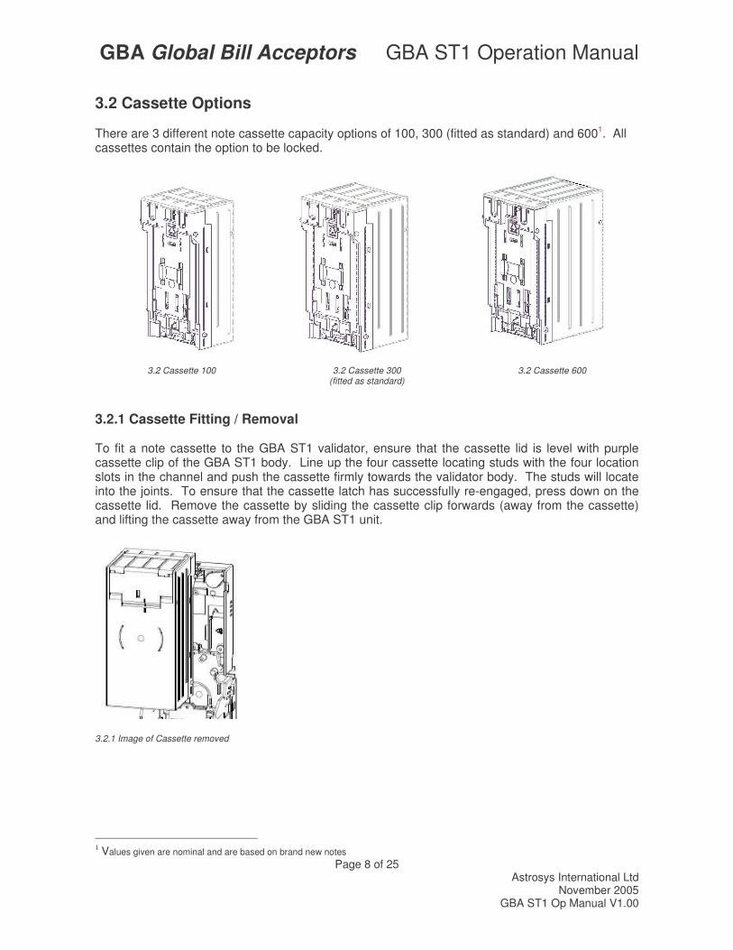
3.2 Cassette Options There are 3 different note cassette capacity options of 100, 300 (fitted as standard) and 6001. All cassettes contain the option to be locked.
3.2 Cassette 100 3.2 Cassette 300
(fitted as standard) 3.2 Cassette 600
3.2.1 Cassette Fitting / Removal To fit a note cassette to the GBA ST1 validator, ensure that the cassette lid is level with purple cassette clip of the GBA ST1 body. Line up the four cassette locating studs with the four location slots in the channel and push the cassette firmly towards the validator body. The studs will locate into the joints. To ensure that the cassette latch has successfully re-engaged, press down on the cassette lid. Remove the cassette by sliding the cassette clip forwards (away from the cassette) and lifting the cassette away from the GBA ST1 unit.
3.2.1 Image of Cassette removed
1 Values given are nominal and are based on brand new notes
GBA Global Bill Acceptors GBA ST1 Operation Manual
Page 9 of 25 Astrosys International Ltd
November 2005 GBA ST1 Op Manual V1.00
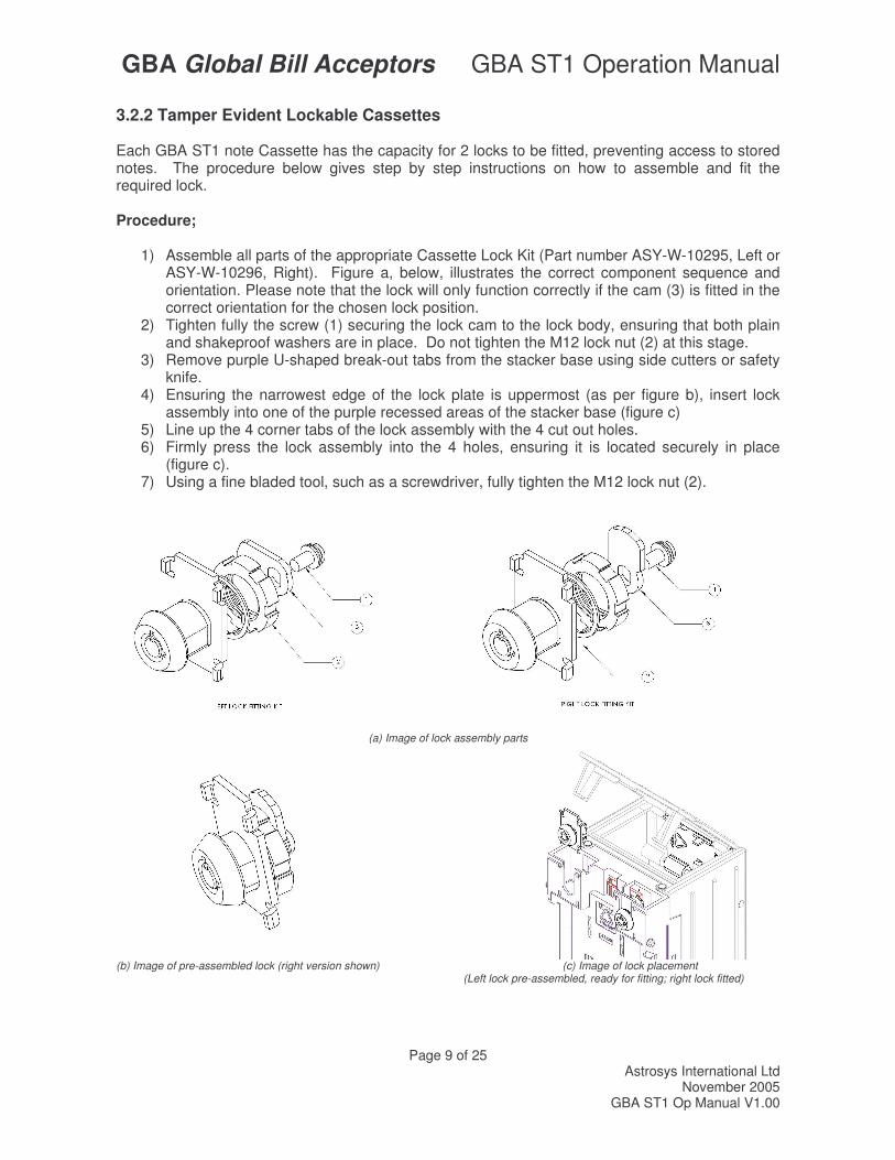
3.2.2 Tamper Evident Lockable Cassettes Each GBA ST1 note Cassette has the capacity for 2 locks to be fitted, preventing access to stored notes. The procedure below gives step by step instructions on how to assemble and fit the required lock. Procedure;
1) Assemble all parts of the appropriate Cassette Lock Kit (Part number ASY-W-10295, Left or ASY-W-10296, Right). Figure a, below, illustrates the correct component sequence and orientation. Please note that the lock will only function correctly if the cam (3) is fitted in the correct orientation for the chosen lock position.
2) Tighten fully the screw (1) securing the lock cam to the lock body, ensuring that both plain and shakeproof washers are in place. Do not tighten the M12 lock nut (2) at this stage.
3) Remove purple U-shaped break-out tabs from the stacker base using side cutters or safety knife.
4) Ensuring the narrowest edge of the lock plate is uppermost (as per figure b), insert lock assembly into one of the purple recessed areas of the stacker base (figure c)
5) Line up the 4 corner tabs of the lock assembly with the 4 cut out holes. 6) Firmly press the lock assembly into the 4 holes, ensuring it is located securely in place
(figure c). 7) Using a fine bladed tool, such as a screwdriver, fully tighten the M12 lock nut (2).
(a) Image of lock assembly parts
(b) Image of pre-assembled lock (right version shown) (c) Image of lock placement
(Left lock pre-assembled, ready for fitting; right lock fitted)
GBA Global Bill Acceptors GBA ST1 Operation Manual
Page 10 of 25 Astrosys International Ltd
November 2005 GBA ST1 Op Manual V1.00
4.0 INTERFACE PROTOCOLS The GBA ST1 can communicate with a host (machine) via one of five base interface protocols. These protocols are; NAMA MDB, pulse, parallel, cctalk® and bi-directional serial (“RS232”). Variants to some of these protocols are also available, please contact your regional office for further details. The product is connected to the host using an appropriate interface cable assembly. With the exception of MDB the GBA ST1 will be connected to the host machine using a cable assembly terminated with a 20-way connector, as denoted in section 8.0 – Electrical Connections.
4.1 NAMA MDB If the GBA ST1 is used in an MDB interface application, an additional interface cable assembly is required (part number ASY-W-10215) to connect to a standard NAMA 6 pin connector. To fit the cable assembly, first remove the MDB Socket Cover from the rear of the Bottom Sensor Assembly to expose the 6 pin connector. 4.2 CCTALK® INTERFACE If the validator is used in a ccTalk® interface application, an alternative 20 pin harness is required. Part Number: ASY-W-10265. Please contact Technical Support for details. For further details relating to the operation of specific interfaces please refer to the Interface Description Manual.
GBA Global Bill Acceptors GBA ST1 Operation Manual
Page 11 of 25 Astrosys International Ltd
November 2005 GBA ST1 Op Manual V1.00
5.0 SOFTWARE CONFIGURATION
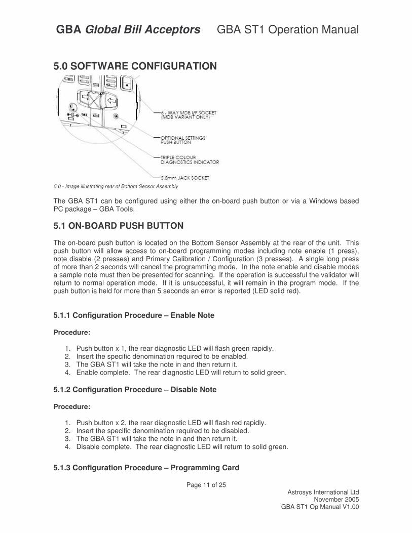
5.0 - Image illustrating rear of Bottom Sensor Assembly
The GBA ST1 can be configured using either the on-board push button or via a Windows based PC package – GBA Tools.
5.1 ON-BOARD PUSH BUTTON The on-board push button is located on the Bottom Sensor Assembly at the rear of the unit. This push button will allow access to on-board programming modes including note enable (1 press), note disable (2 presses) and Primary Calibration / Configuration (3 presses). A single long press of more than 2 seconds will cancel the programming mode. In the note enable and disable modes a sample note must then be presented for scanning. If the operation is successful the validator will return to normal operation mode. If it is unsuccessful, it will remain in the program mode. If the push button is held for more than 5 seconds an error is reported (LED solid red). 5.1.1 Configuration Procedure – Enable Note Procedure:
1. Push button x 1, the rear diagnostic LED will flash green rapidly. 2. Insert the specific denomination required to be enabled. 3. The GBA ST1 will take the note in and then return it. 4. Enable complete. The rear diagnostic LED will return to solid green.
5.1.2 Configuration Procedure – Disable Note Procedure:
1. Push button x 2, the rear diagnostic LED will flash red rapidly. 2. Insert the specific denomination required to be disabled. 3. The GBA ST1 will take the note in and then return it. 4. Disable complete. The rear diagnostic LED will return to solid green.
5.1.3 Configuration Procedure – Programming Card
GBA Global Bill Acceptors GBA ST1 Operation Manual
Page 12 of 25 Astrosys International Ltd
November 2005 GBA ST1 Op Manual V1.00
Equipment Required; Program Card. (PC software is available to print these cards. Please consult your local sales office) Procedure;
1. Push button x3, the rear diagnostic LED will flash orange rapidly. 2. Insert the Program Card into the reader. 3. The Program Card will be taken into the validator and held for a small period of time, then
returned in one smooth movement 4. Configuration is complete.
Note: Please ensure the programming card has been printed on a high quality printer with good solid black lines on the card. 5.1.4 Configuration Procedure – Re-Calibration Although calibration of the GBA ST1 is not a necessity it is recommended periodically for preventative maintenance, and also after any change to the software configuration of the unit. Equipment Required; Calibration Paper. Procedure;
1. The push button is accessible on the Bottom Sensor Assembly, located at the rear of the unit.
2. Push button x3, rear diagnostic LED will rapidly flash orange. 3. Insert the Calibration paper into the reader. 4. The reader will draw in the paper until it reaches the internal string gate. At this point it
will hold the paper momentarily before it is returned. 5. Remove the calibration paper from the note entry point. 6. Calibration is complete.
Note: Please ensure the ST1 calibration paper has 2 chamfered corners. The part number for this is ASY-W-10268
GBA Global Bill Acceptors GBA ST1 Operation Manual
Page 13 of 25 Astrosys International Ltd
November 2005 GBA ST1 Op Manual V1.00
5.2 PC BASED GBA TOOLS The GBA ST1 can also be configured using PC based software, GBA Talk. This software also provides calibration and diagnostic functions.
5.2.1 Configuration Procedure – GBA Talk PC Software Equipment Required; GBA Talk Kit, consisting of PC software, Diagnostic harness and 20 pin harness. Note: the 20 pin harness must contain a 4 pin socket connected to pins 18 and 20. Procedure;
1. Connect the GBA ST1 to the PC by placing the diagnostic harness into the DB9 connector of the PC, and the 4 pin connector into the 4 pin plug of the 20 pin harness.
2. With GBA Talk open, select “Upload” to see on screen the current configuration of the validator.
3. Make the required changes by using the drop down menus, then select the “Set All” button, to send changes to the validator.
4. To complete the procedure, carry out the calibration process by selecting “Calibrate” from the Calibration window.
5.3 SOFTWARE CONFIGURATION OPTIONS: All of the software options below can be set using either the GBATalk PC program or Program Card facility, as mentioned above. Two kinds of program card are available. Firstly a card to set all options (all options must be specified) and secondly individual, specific option cards that will set only key options such as security level, ccTalk® Encryption Key or Note enable / disable. Use Magnetic Sensor Selectable for units fitted with a magnetic reader head, in combination with software containing “C” denotation, e.g., N99C100.STX. Interface: The GBA ST1 can be set for use with the following interfaces:
(1) Pulse (2) Parallel (3) RS232 (4) MDB2 (5) ccTalk® Non Encrypted3 (6) ccTalk® Encrypted3 (7) Parallel XT (8) Parallel Binary (9) Smiley Secure Protocol (SSP)
Definitions of the above can be found in the Interface Description Manual.
2 Note: MDB interface requires the use of a dedicated interface harness to connect to a standard NAMA 6 pin connector. Please contact your distributor or regional office for details. 3 Note: ccTalk® interface requires the use of a dedicated interface harness. Please contact your distributor or regional office for details.
GBA Global Bill Acceptors GBA ST1 Operation Manual
Page 14 of 25 Astrosys International Ltd
November 2005 GBA ST1 Op Manual V1.00
ccTalk® Encryption Key Reset: Should a validator require replacing in a ccTalk® application, the Encryption key will require resetting to the default in both the host machine and the note validator. This is achieved, on the note validator, by use of the ccTalk® Encryption Key Reset Programming Card using the procedure described above, in “Configuration Procedure – Programming Card”. For resetting the host machine please refer to the machine user guide. Escrow Time out period (Parallel interfaces only): This option enables the Escrow time out period to be set in 1-second intervals between 1 and 255 seconds. Please Note: The standard escrow time is 26 seconds. Adjust with care! The host machine must be designed to work with any other time selected. Please contact Technical support for more details. Low Power Mode: In this mode the quiescent current drawn by the unit is reduced by disabling the motor and stacker power up checks at start up. This mode is designed to enable the GBA ST1 to be used in battery applications. It is anticipated that the unit is powered up only when a customer wants to present a note, e.g., by lifting up a flap, then the validator is powered down once transaction completed.
6.0 MECHANICAL INSTALLATION The product can be configured / installed in both Up and Down stacking configurations. With the appropriate faceplate selection it can be mounted either with the faceplate showing at the front of the host machine or with the majority of the faceplate concealed. With the faceplate (and blanking plate) mounted in the host machine, the GBA ST1 unit fitted with the appropriate note guide is simply clipped into place in the faceplate. Please note that the note guide must be fitted to the validator before inserting the validator into the faceplate. For applications where machine abuse is anticipated, the GBA ST1 unit can be secured to the faceplate using two thread-forming screws before the faceplate is fitted into the host machine. Please contact your local regional office for further information. Details of product dimensions can be found at the end of this document.
GBA Global Bill Acceptors GBA ST1 Operation Manual
Page 15 of 25 Astrosys International Ltd
November 2005 GBA ST1 Op Manual V1.00
7.0 ELECTRICAL INTERFACE SPECIFICATION
7.1 Power 7.1.1 Power Supply Voltage: 12VDC +/- 10% Regulated4 Signal Input High Voltage: 5.5VDC Signal Minimum Voltage: 0V
7.1.2 Power Consumption Quiescent: 200mA Validating: 800mA Stacking: 700mA Stalled: 1.4A Maximum Output Low Voltage: 0.4VDC Minimum Output High Voltage: 2.4VDC Maximum output sink current: 50mA @ 12VDC (Open collector) Input pull up to 5V: 21K ohm 7.2 Outputs Open Collector outputs; Maximum Open Voltage 40V Maximum Sink Current 50mA
4 For Power packs, 12vDC connection should be Tip Negative.
GBA Global Bill Acceptors GBA ST1 Operation Manual
Page 16 of 25 Astrosys International Ltd
November 2005 GBA ST1 Op Manual V1.00
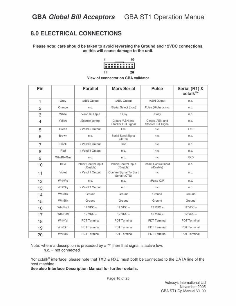
8.0 ELECTRICAL CONNECTIONS
Please note: care should be taken to avoid reversing the Ground and 12VDC connections, as this will cause damage to the unit.
View of connector on GBA validator
Pin Parallel
Mars Serial
Pulse Serial (R1) &
cctalk®*
1 Grey /ABN Output /ABN Output /ABN Output n.c.
2 Orange n.c. /Serial Select (Low) Pulse (High) or n.c. n.c.
3 White /Vend 6 Output /Busy /Busy n.c.
4 Yellow /Escrow control Clears /ABN and Stacker Full Signal
Clears /ABN and Stacker Full Signal
n.c.
5 Green / Vend 5 Output TXD n.c. TXD
6 Brown n.c. Serial Send Signal (/RTS)
n.c. n.c.
7 Black / Vend 3 Output Gnd n.c. n.c.
8 Red / Vend 4 Output n.c. n.c. n.c.
9 Whi/Blk/Grn n.c. n.c. n.c. RXD
10 Blue Inhibit Control Input (/Enable)
Inhibit Control Input (/Enable)
Inhibit Control Input (/Enable)
n.c.
11 Violet / Vend 1 Output Confirm Signal To Start Serial (/CTS)
n.c. n.c.
12 Whi/Vio n.c. n.c. /Pulse O/P n.c.
13 Whi/Gry / Vend 2 Output n.c. n.c. n.c.
14 Whi/Blk Ground Ground Ground Ground
15 Whi/Blk Ground Ground Ground Ground
16 Whi/Red 12 VDC + 12 VDC + 12 VDC + 12 VDC +
17 Whi/Red 12 VDC + 12 VDC + 12 VDC + 12 VDC +
18 Whi/Yel PDT Terminal PDT Terminal PDT Terminal PDT Terminal
19 Whi/Grn PDT Terminal PDT Terminal PDT Terminal PDT Terminal
20 Whi/Blu PDT Terminal PDT Terminal PDT Terminal PDT Terminal
Note: where a description is preceded by a “/” then that signal is active low. n.c. = not connected *for cctalk® interface, please note that TXD & RXD must both be connected to the DATA line of the host machine. See also Interface Description Manual for further details.

GBA Global Bill Acceptors GBA ST1 Operation Manual
Page 17 of 25 Astrosys International Ltd
November 2005 GBA ST1 Op Manual V1.00
Signal Description /ABN (Alarm) Output – low for 100ms (parallel interface) or permanently low to
indicate error or alarm in serial and pulse interfaces.
/VEND n The vend outputs 1 to 6 (parallel interface) are capable of sinking up to 50 MA at 12VDC.
/ESCROW Input - when low this selects Escrow mode
PULSE , /SERIAL select Input - when low selects Mars® Serial (A) mode. High or not connected selects pulse mode
/BUSY Output – a low output indicates when the acceptor is operating
/DATA Output - used to send data to the host machine
/CTS Input - from host that tells acceptor that host is ready to receive the message
/Enable Input - Determines whether or not the acceptor will accept bills. Logic low = accept bills
/RTS (Interrupt) Output to host signal that the acceptor wishes to send a message to the host.
/PULSE O/P The pulse credit output is capable of sinking up to 50mA. The pulse pattern is selectable via the programming card. In the normal mode the pattern is 50mS on/300ms off. In the fast mode a 50mS/50mS pattern results.
TXD Output – UART, open collector
RXD Input – UART, TTL level receive data
GBA Global Bill Acceptors GBA ST1 Operation Manual
Page 18 of 25 Astrosys International Ltd
November 2005 GBA ST1 Op Manual V1.00
9.0 MAINTENANCE
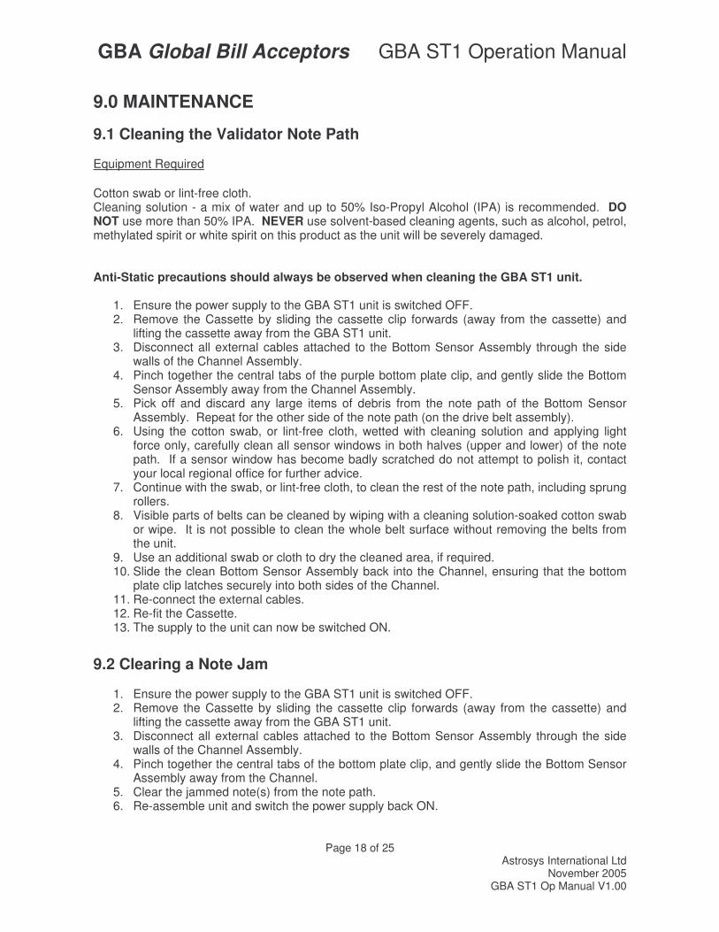
9.1 Cleaning the Validator Note Path Equipment Required Cotton swab or lint-free cloth. Cleaning solution - a mix of water and up to 50% Iso-Propyl Alcohol (IPA) is recommended. DO NOT use more than 50% IPA. NEVER use solvent-based cleaning agents, such as alcohol, petrol, methylated spirit or white spirit on this product as the unit will be severely damaged. Anti-Static precautions should always be observed when cleaning the GBA ST1 unit.
1. Ensure the power supply to the GBA ST1 unit is switched OFF. 2. Remove the Cassette by sliding the cassette clip forwards (away from the cassette) and
lifting the cassette away from the GBA ST1 unit. 3. Disconnect all external cables attached to the Bottom Sensor Assembly through the side
walls of the Channel Assembly. 4. Pinch together the central tabs of the purple bottom plate clip, and gently slide the Bottom
Sensor Assembly away from the Channel Assembly. 5. Pick off and discard any large items of debris from the note path of the Bottom Sensor
Assembly. Repeat for the other side of the note path (on the drive belt assembly). 6. Using the cotton swab, or lint-free cloth, wetted with cleaning solution and applying light
force only, carefully clean all sensor windows in both halves (upper and lower) of the note path. If a sensor window has become badly scratched do not attempt to polish it, contact your local regional office for further advice.
7. Continue with the swab, or lint-free cloth, to clean the rest of the note path, including sprung rollers.
8. Visible parts of belts can be cleaned by wiping with a cleaning solution-soaked cotton swab or wipe. It is not possible to clean the whole belt surface without removing the belts from the unit.
9. Use an additional swab or cloth to dry the cleaned area, if required. 10. Slide the clean Bottom Sensor Assembly back into the Channel, ensuring that the bottom
plate clip latches securely into both sides of the Channel. 11. Re-connect the external cables. 12. Re-fit the Cassette. 13. The supply to the unit can now be switched ON.
9.2 Clearing a Note Jam
1. Ensure the power supply to the GBA ST1 unit is switched OFF. 2. Remove the Cassette by sliding the cassette clip forwards (away from the cassette) and
lifting the cassette away from the GBA ST1 unit. 3. Disconnect all external cables attached to the Bottom Sensor Assembly through the side
walls of the Channel Assembly. 4. Pinch together the central tabs of the bottom plate clip, and gently slide the Bottom Sensor
Assembly away from the Channel. 5. Clear the jammed note(s) from the note path. 6. Re-assemble unit and switch the power supply back ON.
GBA Global Bill Acceptors GBA ST1 Operation Manual
Page 19 of 25 Astrosys International Ltd
November 2005 GBA ST1 Op Manual V1.00
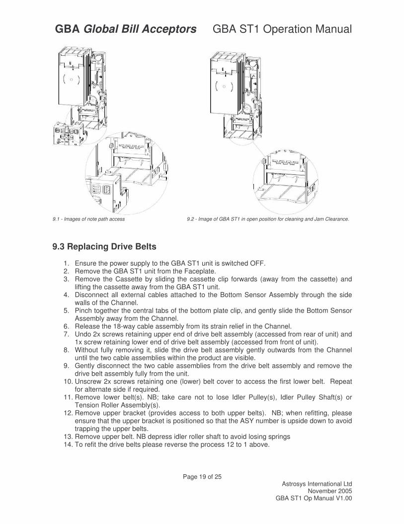
9.1 - Images of note path access 9.2 - Image of GBA ST1 in open position for cleaning and Jam Clearance.
9.3 Replacing Drive Belts
1. Ensure the power supply to the GBA ST1 unit is switched OFF. 2. Remove the GBA ST1 unit from the Faceplate. 3. Remove the Cassette by sliding the cassette clip forwards (away from the cassette) and
lifting the cassette away from the GBA ST1 unit. 4. Disconnect all external cables attached to the Bottom Sensor Assembly through the side
walls of the Channel. 5. Pinch together the central tabs of the bottom plate clip, and gently slide the Bottom Sensor
Assembly away from the Channel. 6. Release the 18-way cable assembly from its strain relief in the Channel. 7. Undo 2x screws retaining upper end of drive belt assembly (accessed from rear of unit) and
1x screw retaining lower end of drive belt assembly (accessed from front of unit). 8. Without fully removing it, slide the drive belt assembly gently outwards from the Channel
until the two cable assemblies within the product are visible. 9. Gently disconnect the two cable assemblies from the drive belt assembly and remove the
drive belt assembly fully from the unit. 10. Unscrew 2x screws retaining one (lower) belt cover to access the first lower belt. Repeat
for alternate side if required. 11. Remove lower belt(s). NB; take care not to lose Idler Pulley(s), Idler Pulley Shaft(s) or
Tension Roller Assembly(s). 12. Remove upper bracket (provides access to both upper belts). NB; when refitting, please
ensure that the upper bracket is positioned so that the ASY number is upside down to avoid trapping the upper belts.
13. Remove upper belt. NB depress idler roller shaft to avoid losing springs 14. To refit the drive belts please reverse the process 12 to 1 above.
GBA Global Bill Acceptors GBA ST1 Operation Manual
Page 20 of 25 Astrosys International Ltd
November 2005 GBA ST1 Op Manual V1.00
10.0 DIAGNOSTICS & TROUBLESHOOTING
10.1 DIAGNOSTICS
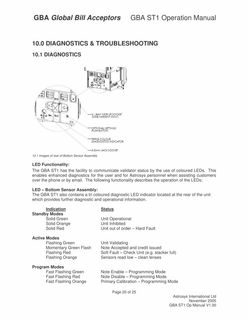
10.1 Images of rear of Bottom Sensor Assembly
LED Functionality: The GBA ST1 has the facility to communicate validator status by the use of coloured LEDs. This enables enhanced diagnostics for the user and for Astrosys personnel when assisting customers over the phone or by email. The following functionality describes the operation of the LEDs; LED – Bottom Sensor Assembly: The GBA ST1 also contains a tri coloured diagnostic LED indicator located at the rear of the unit which provides further diagnostic and operational information. Indication Status Standby Modes Solid Green Unit Operational Solid Orange Unit Inhibited Solid Red Unit out of order – Hard Fault Active Modes Flashing Green Unit Validating Momentary Green Flash Note Accepted and credit issued
Flashing Red Soft Fault – Check Unit (e.g. stacker full) Flashing Orange Sensors read low – clean lenses Program Modes Fast Flashing Green Note Enable – Programming Mode Fast Flashing Red Note Disable – Programming Mode Fast Flashing Orange Primary Calibration – Programming Mode
GBA Global Bill Acceptors GBA ST1 Operation Manual
Page 21 of 25 Astrosys International Ltd
November 2005 GBA ST1 Op Manual V1.00
LED – Face Plate: The GBA ST1, when fitted with the External (illuminated) face plate, will indicate status to the end user via three LEDs situated in the centre of the faceplate – two green, one red – as follows;
Indication Status Flashing Green Unit ready to accept notes Solid Green Unit validating Solid Red Unit out of order No LED colour Note returning or loss of power
LED - Flashing Note guide: The GBA ST1 has an optional illuminated, tri colour, note guide to further assist in indicating the status of the validator to the end user. Indication Status Flashing Green towards note entry Unit ready to accept notes Solid Green Unit validating Flashing Orange away from note entry Note returning Fading from Red to Green Unit in power up routine
Solid Red Unit out of order
GBA Global Bill Acceptors GBA ST1 Operation Manual
Page 22 of 25 Astrosys International Ltd
November 2005 GBA ST1 Op Manual V1.00
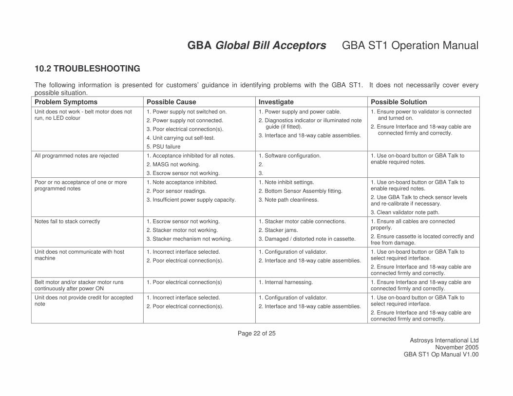
10.2 TROUBLESHOOTING The following information is presented for customers’ guidance in identifying problems with the GBA ST1. It does not necessarily cover every possible situation. Problem Symptoms Possible Cause Investigate Possible Solution Unit does not work - belt motor does not run, no LED colour
1. Power supply not switched on.
2. Power supply not connected.
3. Poor electrical connection(s).
4. Unit carrying out self-test.
5. PSU failure
1. Power supply and power cable.
2. Diagnostics indicator or illuminated note guide (if fitted).
3. Interface and 18-way cable assemblies.
1. Ensure power to validator is connected and turned on.
2. Ensure Interface and 18-way cable are connected firmly and correctly.
All programmed notes are rejected 1. Acceptance inhibited for all notes.
2. MASG not working.
3. Escrow sensor not working.
1. Software configuration.
2.
3.
1. Use on-board button or GBA Talk to enable required notes.
Poor or no acceptance of one or more programmed notes
1. Note acceptance inhibited.
2. Poor sensor readings.
3. Insufficient power supply capacity.
1. Note inhibit settings.
2. Bottom Sensor Assembly fitting.
3. Note path cleanliness.
1. Use on-board button or GBA Talk to enable required notes.
2. Use GBA Talk to check sensor levels and re-calibrate if necessary.
3. Clean validator note path.
Notes fail to stack correctly 1. Escrow sensor not working.
2. Stacker motor not working.
3. Stacker mechanism not working.
1. Stacker motor cable connections.
2. Stacker jams.
3. Damaged / distorted note in cassette.
1. Ensure all cables are connected properly.
2. Ensure cassette is located correctly and free from damage.
Unit does not communicate with host machine
1. Incorrect interface selected.
2. Poor electrical connection(s).
1. Configuration of validator.
2. Interface and 18-way cable assemblies.
1. Use on-board button or GBA Talk to select required interface.
2. Ensure Interface and 18-way cable are connected firmly and correctly.
Belt motor and/or stacker motor runs continuously after power ON
1. Poor electrical connection(s) 1. Internal harnessing. 1. Ensure Interface and 18-way cable are connected firmly and correctly.
Unit does not provide credit for accepted note
1. Incorrect interface selected.
2. Poor electrical connection(s).
1. Configuration of validator.
2. Interface and 18-way cable assemblies.
1. Use on-board button or GBA Talk to select required interface.
2. Ensure Interface and 18-way cable are connected firmly and correctly.
GBA Global Bill Acceptors GBA ST1 Operation Manual
Page 23 of 25 Astrosys International Ltd
November 2005 GBA ST1 Op Manual V1.00
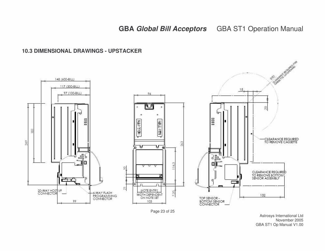
10.3 DIMENSIONAL DRAWINGS - UPSTACKER
GBA Global Bill Acceptors GBA ST1 Operation Manual
Page 24 of 25 Astrosys International Ltd
November 2005 GBA ST1 Op Manual V1.00
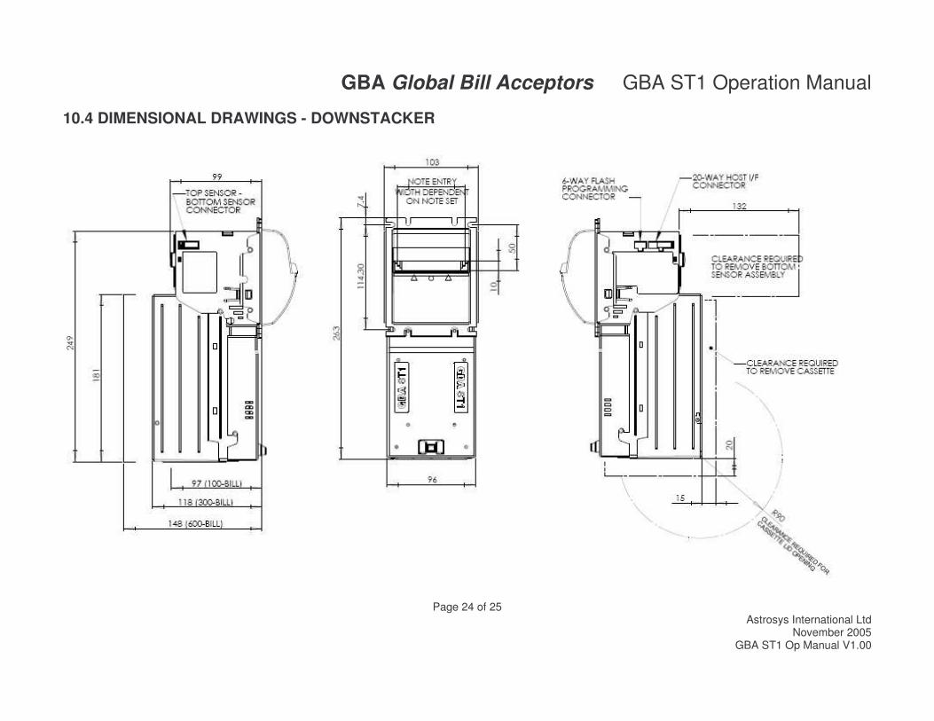
10.4 DIMENSIONAL DRAWINGS - DOWNSTACKER
GBA Global Bill Acceptors GBA ST1 Operation Manual
Page 25 of 25 Astrosys International Ltd
November 2005 GBA ST1 Op Manual V1.00
Revision History Revision Date Created Approved Comments
1.00 05 MAY 06 Steve Priest
Mike Palmer
Initial issue.
Astrosys International Ltd. reserves the right to amend, improve or otherwise change this document or the product referred to herein at any time.
Astrosys International Ltd. does not accept liability for any errors contained within, or omissions from, this document. Astrosys International Ltd. shall not incur any penalties arising from the adherence to, reliance on or interpretation of this document.
REGIONAL OFFICES AstroSystems Ltd Microsystem Controls Pty Ltd 1 The Quadrangle Unit D2.0 Ground Floor Grove Technology Park 63-85 Turner Street Wantage Port Melbourne Oxon. OX12 9FA Victoria 3207 U.K. Australia Tel: +44 (0) 1235 772201 Tel: +613 9646 6446 Fax: +44 (0) 1235 772202 Fax: +613 9646 6447 E-Mail:[email protected] E-Mail: [email protected] AstroSystems Inc. AstroSystems (Far East) Ltd. 4210 Production Court 2/F 28 Hung to Road Las Vegas Kwun Tong Nv 89115 Kowloon USA. Hong Kong Tel: +1 702 643 1600 Tel: +852 2342 6123 Fax: +1 702 643 1717 Fax: +852 2342 6105 E-Mail:[email protected] E-Mail: [email protected]